

Page 1
APPENDIX
C
Installing and Upgrading Memory and
Virtual Private Network Modules
This appendix tells how to install or upgrade memory and how to install a Virtual
Private Memory (VPN) module in your Cisco 1701 router and includes the
following sections:
• Safety Warnings
• Opening the Chassis
• Locating Modules
• Installing a DIMM
• Installing a VPN Module
• Closing the Chassis
Safety Warnings
Warning
Warning
OL-3954-02
During this procedure, wear grounding wrist straps to avoid ESD damage to the
router. Do not directly touch the backplane with your hand or any metal tool, or
you could shock yourself.
Only trained and qualified personnel should be allowed to install or replace this
equipment.
Cisco 1701 ADSL Security Access Router Hardware Installation Guide
C-1
Page 2
Opening the Chassis
Appendix C Installing and Upgrading Memory and Virtual Private Network Modules
Warning
Warning
Warning
Warning
Warning
Before working on a system that has an on/off switch, turn OFF the power and
unplug the power cord.
Do not work on the system or connect or disconnect cables during periods of
lightning activity.
Read the installation instructions before you connect the system to its power
source.
Before working on equipment that is connected to power lines, remove jewelry
(including rings, necklaces, and watches). Metal objects will heat up when
connected to power and ground and can cause serious burns or weld the metal
object to the terminals.
Hazardous network voltages are present in WAN ports regardless of whether
power to the router is OFF or ON. To avoid electric shock, use caution when
working near WAN ports. When detaching cables, detach the end away from
the router first.
Opening the Chassis
In order to upgrade Cisco 1701 router memory, you must open the chassis.
Opening the chassis requires a number one Phillips screwdriver.
Follow these steps to open the chassis:
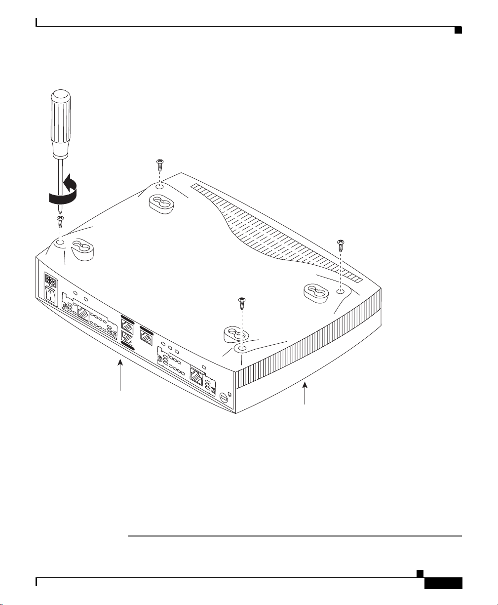
Step 1 Make sure the router is turned off and is disconnected from the power supply.
Step 2 Turn the router upside down, and rest the top of the router on a flat surface.
Step 3 Use the Phillips screwdriver to remove the four screws that hold the top and
bottom of the chassis together, as shown in Figure C-1.
Cisco 1701 ADSL Security Access Router Hardware Installation Guide
C-2
OL-3954-02
Page 3
Appendix C Installing and Upgrading Memory and Virtual Private Network Modules
Figure C-1 Removing the Chassis Screws
#1 Phillips screwdriver
+5, +12, -12
OK
WIC1
MOD OK
S/T
BRI
N
IO
T
A
L
CD
L
A
T
S
IN
E
R
O
F
E
B
L
A
U
N
A
B2
M
E
E
S
B
1
AUX
CONSOLE
10/100 ETH
LINK
100
FDX
1ADSL
IC
K
W
O
P
L
D
N
C
IO
T
OK
A
L
L
A
T
L
S
A
U
IN
N
A
M
WIC0
E
R
O
E
F
E
E
S
B
ADSL
Cisco 1701
Opening the Chassis
OL-3954-02
Rear panel
Step 4
Top of router
Turn the router back to its original position (top up).
91524
Step 5 Gently pull the top of the router (which is facing up toward you) up and away from
the bottom of the router (which is resting on the flat surface).
At this point, you might have to disconnect the fan, which is inside the top of the
router chassis, from the motherboard. Do this by disconnecting the fan cable from
the connector (labeled FAN) on the motherboard.
Step 6 Place the router bottom on an antistatic mat, and begin installing memory.
Cisco 1701 ADSL Security Access Router Hardware Installation Guide
C-3
Page 4

Appendix C Installing and Upgrading Memory and Virtual Private Network Modules
[][]
Locating Modules
Locating Modules
Figure C-2 shows where to find slots for a dual in-line memory module (DIMM)
and a VPN module on the router motherboard.
Figure C-2 Cisco 1700 Motherboard—Memory Locations
Rear panel of router
WAN interface card slot
WAN interface card slot
DIMM slot VPN slot VPN standoff
Boot ROM
91536
holes
C-4
Cisco 1701 ADSL Security Access Router Hardware Installation Guide
OL-3954-02
Page 5

Appendix C Installing and Upgrading Memory and Virtual Private Network Modules
Installing a DIMM
You can install a DIMM to increase the amount of dynamic random-access
memory (DRAM) in the router.
Follow these steps to install a DIMM on the router motherboard:
Step 1 Locate the DIMM slot on the motherboard.
Step 2 Remove any existing DIMM by pulling the DIMM slot guides (shown in
Figure C-3) away from the DIMM and down toward the motherboard.
Figure C-3 Installing a DIMM
DIMM
2
DIMM slot
1
Installing a DIMM
2
OL-3954-02
DIMM slot guides
Step 3 Insert the DIMM into the DIMM slot, making sure that the notches on the edge of
42289
the DIMM are inserted over the bars inside the DIMM slot, as in Figure C-3.
Step 4 Firmly press the DIMM into the slot until the two DIMM slot guides on each side
of the slot move up and over the end of the DIMM, as in Figure C-3. If the guides
do not move up over the edge of the DIMM, move them with your hands.
Cisco 1701 ADSL Security Access Router Hardware Installation Guide
C-5
Page 6

Appendix C Installing and Upgrading Memory and Virtual Private Network Modules
Installing a VPN Module
Installing a VPN Module
Follow the steps in this section to install a VPN module.
Step 1 Install the two standoffs on the module, as shown in Figure C-4.
Figure C-4 Installing the Standoffs on the VPN Module
Screw
Standoff
Screw
Standoff is installed
into the hole just behind
the large connector.
C-6
46084
Cisco 1701 ADSL Security Access Router Hardware Installation Guide
OL-3954-02
Page 7

Appendix C Installing and Upgrading Memory and Virtual Private Network Modules
Step 2 Locate the VPN module socket, and insert the VPN module, as shown in
Figure C-5.
Figure C-5 VPN Module Location
Installing a VPN Module
9153791538
Step 3
Pushing down as indicated in Figure C-6, plug the VPN module into the socket.
Figure C-6 Seating the VPN Module
Cisco 1701 ADSL Security Access Router Hardware Installation Guide
OL-3954-02
C-7
Page 8

Installing a VPN Module
Step 4 Turn the motherboard over, and attach the standoffs to it by using the screws
Appendix C Installing and Upgrading Memory and Virtual Private Network Modules
provided, as shown in Figure C-7.
Figure C-7 Securing the Standoff to the Router Motherboard
Standoff screws
C-8
Bottom of the board
45919
Cisco 1701 ADSL Security Access Router Hardware Installation Guide
OL-3954-02
Page 9

Appendix C Installing and Upgrading Memory and Virtual Private Network Modules
Closing the Chassis
After installing memory or a VPN module on the motherboard, close the chassis
by following these steps:
Step 1 If you disconnected the fan from the motherboard as described in the “Opening
the Chassis” section, reconnect the fan cable to the connector labeled FAN on the
motherboard.
Step 2 Locate the posts that protrude from the inside of the chassis cover, and locate the
corresponding openings on the chassis bottom.
Step 3 Line up the posts with the corresponding openings, as shown in Figure C-8, and
carefully slide the posts into the openings, taking care not to damage the router
motherboard with the posts.
Closing the Chassis
OL-3954-02
Cisco 1701 ADSL Security Access Router Hardware Installation Guide
C-9
Page 10

Closing the Chassis
Figure C-8 Closing the Chassis
A
D
S
BEFORE INSTALLATION
L
SEE MANUAL
CD LP O
K
W
IC
1A
D
S
L
Appendix C Installing and Upgrading Memory and Virtual Private Network Modules
C-10
91535
1
B
S
E
2
E
M
B
A
N
U
A
L B
E
F
O
R
E
IN
S
TA
D
LL
C
A
T
IO
N
BRI
S/T
Step 4 Replace the screws that you removed when you opened the chassis. (See
Figure C-1.)
Cisco 1701 ADSL Security Access Router Hardware Installation Guide
OL-3954-02
 Loading...