

Page 1

Cisco 1700 Router Hardware Installation Guide
Corporate Headquarters
Cisco Systems, Inc.
170 West Tasman Drive
San Jose, CA 95134-1706
USA
http://www.cisco.com
Tel: 408 526-4000
800 553-NETS (6387)
Fax: 408 526-4100
Customer Order Number: DOC-785405=
Text Part Number: 78-5405-03
Page 2

THE SPECIFICATIONS AND INFORMATION REGARDING THE PRODUCTS IN THIS MANUAL ARE SUBJECT TO CHANGE WITHOUT
NOTICE. ALL STATEMENTS, INFORMATION, AND RECOMMENDATIONS IN THIS MANUAL ARE BELIEVED TO BE ACCURATE BUT ARE
PRESENTED WITHOUT WARRANTY OF ANY KIND, EXPRESS OR IMPLIED. USERS MUST TAKE FULL RESPONSIBILITY FOR THEIR
APPLICATION OF ANY PRODUCTS.
THE SOFTWARE LICENSE AND LIMITED WARRANTY FOR THE ACCOMPANYING PRODUCT ARE SET FORTH IN THE INFORMATION
PACKET THAT SHIPPED WITH THE PRODUCT AND ARE INCORPORATED HEREIN BY THIS REFERENCE. IF YOU ARE UNABLE TO
LOCATE THE SOFTWARE LICENSE OR LIMITED WARRANTY, CONTACT YOUR CISCO REPRESENTATIVE FOR A COPY.
The following information is for FCC compliance of Class A devices: This equipment has been tested and found to comply with the limits for a Class A
digital device, pursuant to part 15 of the FCC rules. These limits are designed to provide reasonable protection against harmful interference when the
equipment is operated in a commercial environment. This equipment generates, uses, and can radiate radio-frequency energy and, if not installed and used
in accordance with the instruction manual, may cause harmful interference to radio communications. Operation of this equipment in a residential area is
likely to cause harmful interference, in which case users will be required to correct the interference at their own expense.
The following information is for FCC compliance of Class B devices: The equipment described in this manual generates and may radiate radio-frequency
energy. If it is not installed in accordance with Cisco’s installation instructions, it may cause interference with radio and tel evision reception. This equipment
has been tested and found to comply with the limits for a Class B digital device in accordance with the specifications in part 15 of the FCC rules. These
specifications are designed to provide reasonable protection against such interference in a residential installation. However, there is no guarantee that
interference will not occur in a particular installation.
Modifying the equipment without Cisco’s written authorization may result in the equipment no longer complying with FCC requirements for Class A or
Class B digital devices. In that event, your right to use the equipment may be limited by FCC regulations, and you may be required to correct any interference
to radio or television communications at your own expense.
You can determine whether your equipment is causing interference by turning it off. If the interference stops, it was probably caused by the Cisco equipment
or one of its peripheral devices. If the equipment causes interference to radio or television reception, try to correct the interference by using one or more of
the following measures:
• Turn the television or radio antenna until the interference stops.
• Move the equipment to one side or the other of the television or radio.
• Move the equipment farther away from the television or radio.
• Plug the equipment into an outlet that is on a different circuit from the television or radio. (That is, make certain the equipment and the television or radio
are on circuits controlled by different circuit breakers or fuses.)
Modifications to this product not authorized by Cisco Systems, Inc. could void the FCC approval and negate your authority to operate the product.
The Cisco implementation of TCP header compression is an adaptation of a program developed by the University of California, Berkeley (UCB) as part of
UCB’s public domain version of the UNIX operating system. All rights reserved. Copyright © 1981, Regents of the University of California.
NOTWITHSTANDING ANY OTHER WARRANTY HEREIN, ALL DOCUMENT FILES AND SOFTWARE OF THESE SUPPLIERS ARE
PROVIDED “AS IS” WITH ALL FAULTS. CISCO AND THE ABOVE-NAMED SUPPLIERS DISCLAIM ALL WARRANTIES, EXPRESSED
OR IMPLIED, INCLUDING, WITHOUT LIMITATION, THOSE OF MERCHANTABILITY, FITNESS FOR A PARTICULAR PURPOSE AND
NONINFRINGEMENT OR ARISING FROM A COURSE OF DEALING, USAGE, OR TRADE PRACTICE.
IN NO EVENT SHALL CISCO OR ITS SUPPLIERS BE LIABLE FOR ANY INDIRECT, SPECIAL, CONSEQUENTIAL, OR INCIDENTAL
DAMAGES, INCLUDING, WITHOUT LIMITATION, LOST PROFITS OR LOSS OR DAMAGE TO DATA ARISING OUT OF THE USE OR
INABILITY TO USE THIS MANUAL, EVEN IF CISCO OR ITS SUPPLIERS HAVE BEEN ADVISED OF THE POSSIBILITY OF SUCH DAMAGES.
Page 3

CCSP, CCVP, the Cisco Square Bridge logo, Follow Me Browsing, and StackWise are trademarks of Cisco Systems, Inc.; Changing the Way We
Work, Live, Play, and Learn, and iQuick Study are service marks of Cisco Systems, Inc.; and Access Registrar, Aironet, ASIST, BPX, Catalyst,
CCDA, CCDP, CCIE, CCIP, CCNA, CCNP, Cisco, the Cisco Certified Internetwork Expert logo, Cisco IOS, Cisco Press, Cisco Systems, Cisco
Systems Capital, the Cisco Systems logo, Cisco Unity, Empowering the Internet Generation, Enterprise/Solver, EtherChannel, EtherFast,
EtherSwitch, Fast Step, FormShare, GigaDrive, GigaStack, HomeLink, Internet Quotient, IOS, IP/TV, iQ Expertise, the iQ logo, iQ Net Readiness
Scorecard, LightStream, Linksys, MeetingPlace, MGX, the Networkers logo, Networking Academy, Network Registrar, Pack et, PIX, Post-Routing,
Pre-Routing, ProConnect, RateMUX, ScriptShare, SlideCast, SMARTnet, StrataView Plus, TeleRouter, The Fastest Way to Increase Your Internet
Quotient, and TransPath are registered trademarks of Cisco Systems, Inc. and/or its affiliates in the United States and certain other countries.
All other trademarks mentioned in this document or Website are the property of their respective owners. The use of the word partner does not imply
a partnership relationship between Cisco and any other company. (0502R)
Cisco 1700 Router Hardware Installation Guide
Copyright © 2005 Cisco Systems, Inc. All rights reserved.
Page 4

Page 5

About This Guide ix
Audience and Scope ix
Organization x
Related Publications x
Conventions xi
Obtaining Documentation xiv
Cisco.com xiv
Documentation DVD xiv
Ordering Documentation xv
Documentation Feedback xv
Cisco Product Security Overview xv
Reporting Security Problems in Cisco Products xvi
CONTENTS
CHAPTER
78-5405-03
Obtaining Technical Assistance xvii
Cisco Technical Support Website xvii
Submitting a Service Request xviii
Definitions of Service Request Severity xviii
Obtaining Additional Publications and Information xix
1 Cisco 1700 Router Overview 1-1
Key Features 1-3
Rear-Panel Ports and LEDs 1-4
Front-Panel LEDs 1-6
Router Memory 1-8
Types of Memory 1-8
Cisco 1700 Router Hardware Installation Guide
v
Page 6

Contents
Amounts of Memory 1-9
Unpacking the Router 1-10
Additional Required Equipment 1-10
CHAPTER
CHAPTER
2 Installing the Cisco 1700 Router 2-1
Before Installing the Router 2-1
Connecting the Router to Your Local Network 2-2
Installing WAN Interface Cards 2-4
Safety Information 2-4
Installing a WAN Interface Card 2-5
Connecting Power to the Router 2-8
Verifying Your Installation 2-10
Optional Installation Steps 2-11
Connecting a PC 2-11
Connecting a Modem 2-12
Wall-Mounting 2-14
3 Troubleshooting 3-1
Contacting Cisco or Your Reseller 3-1
Recovering a Lost Password 3-2
Change the Configuration Register 3-2
Reset the Router 3-4
Reset the Password 3-5
Reset the Configuration Register Value 3-6
vi
Problem Solving 3-6
OK LED Diagnostics 3-7
Troubleshooting WAN Interface Cards and Cables 3-7
Troubleshooting the Power System 3-9
Cisco 1700 Router Hardware Installation Guide
78-5405-03
Page 7

Troubleshooting ISDN 3-10
Contents
APPENDIX
APPENDIX
APPENDIX
APPENDIX
A Technical Specifications A-1
B Cabling Specifications B-1
Ethernet Cables B-2
Ethernet Network Cabling Guidelines B-3
Console Cable and Adapters B-3
C Installing and Upgrading Router Memory C-1
Opening the Chassis C-2
Locating Memory C-4
Installing a Mini-Flash Module C-5
Removing a Mini-Flash Module C-6
Installing a DIMM C-7
Closing the Chassis C-8
D Ordering and Configuring an ISDN Line D-1
ISDN BRI Line Configuration Requirements D-1
78-5405-03
ISDN BRI Switch Types D-2
ISDN BRI Provisioning by Switch Type D-3
Defining ISDN Service Profile Identifiers D-4
ISDN Configuration Options D-5
Snapshot Routing D-5
Dial-on-Demand Routing D-6
Bandwidth on Demand and Dial Backup D-6
Cisco 1700 Router Hardware Installation Guide
vii
Page 8

Contents
viii
Cisco 1700 Router Hardware Installation Guide
78-5405-03
Page 9

About This Guide
This section discusses the intended audience, scope, and organization of the
Cisco 1700 Router Hardware Installation Guide and defines the conventions used
to convey instructions and information.
Cisco documentation and additional literature are available on the World Wide
Web at http://www.cisco.com, http://www-china.cisco.com, or
http://www-europe.cisco.com.
If you are reading Cisco product documentation on the World Wide Web, you can
submit comments electronically. Click Feedback in the toolbar, and select
Documentation. After you complete the form, click Submit to send it to Cisco.
We appreciate your comments.
Audience and Scope
This guide is for users who have some experience installing and maintaining
networking hardware. We assume that Cisco 1700 router users are familiar with
the terminology and concepts of local Ethernet and wide-area networking.
This guide describes the functional and physical features of the Cisco 1700 router
and provides installation procedures, troubleshooting information, technical
specifications, and cable and connector guidelines and specifications.
78-5405-03
Cisco 1700 Router Hardware Installation Guide
ix
Page 10

Organization
This guide is organized as follows:
• The chapter “Cisco 1700 Router Overview” describes the router features and
describes the front-panel LEDs, rear-panel LEDs, and connectors.
• The chapter “Installing the Cisco 1700 Router” describes how to install the
router by connecting cables, power, and installing WAN interface cards.
• The chapter “Troubleshooting” describes some problems that you might have
with the router and how to solve these problems.
• The appendix “Technical Specifications” lists the physical characteristics,
environmental requirements, and power specifications for the router.
• The appendix “Cabling Specifications” lists the physical characteristics of
the cables and connectors used with the router.
• The appendix “Installing and Upgrading Router Memory” describes how to
ugrade existing memory or install new memory in your router.
• The appendix “Ordering and Configuring an ISDN Line” describes how to
order and configure ISDN line so that it will operate with your Cisco 1700
router.
Related Publications
The following publications provide related information on this product:
• Installing Your Cisco 1700 Router is the quick-start guide that came with
your router. It has instructions for quickly cabling the router, installing WAN
interface cards, and powering up the router.
• Cisco 1700 Router Software Configuration Guide describes some common
network scenarios and how to use the Cisco IOS command-line interface
(CLI) to configure the router in these scenarios.
• Cisco WAN Interface Cards Hardware Installation Guide describes how to
install and configure all the WAN interface cards that are supported by the
Cisco 1700 router.
Cisco 1700 Router Hardware Installation Guide
x
78-5405-03
Page 11
Conventions
This guide uses the following conventions for instructions and information:
Note This note symbol means reader take note. Notes contain helpful suggestions or
references to materials not contained in this manual.
Caution This caution symbol means reader be careful. In this situation, you might do
something that could result in equipment damage or loss of data.
• Cisco IOS command reference and configuration guides provide complete
information about all Cisco IOS CLI commands and how to use them, as well
as information on designing and configuring local and wide-area networks.
78-5405-03
Warning
Warning
This warning symbol means danger. You are in a situation that could cause
bodily injury. Before you work on any equipment, be aware of the hazards
involved with electrical circuitry and be familiar with standard practices for
preventing accidents. To see translations of the warnings that appear in this
publication, refer to the Regulatory Compliance and Safety Information
document that accompanied this device.
Waarschuwing
een situatie die lichamelijk letsel kan veroorzaken. Voordat u aan enige
apparatuur gaat werken, dient u zich bewust te zijn van de bij elektrische
schakelingen betrokken risico's en dient u op de hoogte te zijn van standaard
maatregelen om ongelukken te voorkomen. Voor vertalingen van de
waarschuwingen die in deze publicatie verschijnen, kunt u het document
Regulatory Compliance and Safety Information (Informatie over naleving van
veiligheids- en andere voorschriften) raadplegen dat bij dit toestel is
ingesloten.
Dit waarschuwingssymbool betekent gevaar. U verkeert in
Cisco 1700 Router Hardware Installation Guide
xi
Page 12

Warning
Warning
Warning
Varoit us
Tämä varoitusmerkki merkitsee vaaraa. Olet tilanteessa, joka voi
johtaa ruumiinvammaan. Ennen kuin työskentelet minkään laitteiston parissa,
ota selvää sähkökytkentöihin liittyvistä vaaroista ja tavanomaisista
onnettomuuksien ehkäisykeinoista. Tässä julkaisussa esiintyvien varoitusten
käännökset löydät laitteen mukana olevasta Regulatory Compliance and Safety
Information -kirjasesta (määräysten noudattaminen ja tietoa turvallisuudesta).
Attention
Ce symbole d'avertissement indique un danger. Vous vous trouvez
dans une situation pouvant causer des blessures ou des dommages corporels.
Avant de travailler sur un équipement, soyez conscient des dangers posés par
les circuits électriques et familiarisez-vous avec les procédures couramment
utilisées pour éviter les accidents. Pour prendre connaissance des traductions
d’avertissements figurant dans cette publication, consultez le document
Regulatory Compliance and Safety Information (Conformité aux règlements et
consignes de sécurité) qui accompagne cet appareil.
Warnung
Dieses Warnsymbol bedeutet Gefahr. Sie befinden sich in einer
Situation, die zu einer Körperverletzung führen könnte. Bevor Sie mit der Arbeit
an irgendeinem Gerät beginnen, seien Sie sich der mit elektrischen
Stromkreisen verbundenen Gefahren und der Standardpraktiken zur
Vermeidung von Unfällen bewußt. Übersetzungen der in dieser
Veröffentlichung enthaltenen Warnhinweise finden Sie im Dokument
Regulatory Compliance and Safety Information (Informationen zu behördlichen
Vorschriften und Sicherheit), das zusammen mit diesem Gerät geliefert wurde.
xii
Warning
Avvertenza
Questo simbolo di avvertenza indica un pericolo. La situazione
potrebbe causare infortuni alle persone. Prima di lavorare su qualsiasi
apparecchiatura, occorre conoscere i pericoli relativi ai circuiti elettrici ed
essere al corrente delle pratiche standard per la prevenzione di incidenti. La
traduzione delle avvertenze riportate in questa pubblicazione si trova nel
documento Regulatory Compliance and Safety Information (Conformità alle
norme e informazioni sulla sicurezza) che accompagna questo dispositivo.
Cisco 1700 Router Hardware Installation Guide
78-5405-03
Page 13

Warning
Warning
Warning
Advarsel
Dette varselsymbolet betyr fare. Du befinner deg i en situasjon som
kan føre til personskade. Før du utfører arbeid på utstyr, må du vare
oppmerksom på de faremomentene som elektriske kretser innebærer, samt
gjøre deg kjent med vanlig praksis når det gjelder å unngå ulykker. Hvis du vil
se oversettelser av de advarslene som finnes i denne publikasjonen, kan du se
i dokumentet Regulatory Compliance and Safety Information (Overholdelse av
forskrifter og sikkerhetsinformasjon) som ble levert med denne enheten.
Aviso
Este símbolo de aviso indica perigo. Encontra-se numa situação que lhe
poderá causar danos físicos. Antes de começar a trabalhar com qualquer
equipamento, familiarize-se com os perigos relacionados com circuitos
eléctricos, e com quaisquer práticas comuns que possam prevenir possíveis
acidentes. Para ver as traduções dos avisos que constam desta publicação,
consulte o documento Regulatory Compliance and Safety Information
(Informação de Segurança e Disposições Reguladoras) que acompanha este
dispositivo.
¡Advertencia!
Este símbolo de aviso significa peligro. Existe riesgo para su
integridad física. Antes de manipular cualquier equipo, considerar los riesgos
que entraña la corriente eléctrica y familiarizarse con los procedimientos
estándar de prevención de accidentes. Para ver una traducción de las
advertencias que aparecen en esta publicación, consultar el documento
titulado Regulatory Compliance and Safety Information (Información sobre
seguridad y conformidad con las disposiciones reglamentarias) que se
acompaña con este dispositivo.
78-5405-03
Warning
Varning !
Denna varningssymbol signalerar fara. Du befinner dig i en situation
som kan leda till personskada. Innan du utför arbete på någon utrustning måste
du vara medveten om farorna med elkretsar och känna till vanligt förfarande för
att förebygga skador. Se förklaringar av de varningar som förkommer i denna
publikation i dokumentet Regulatory Compliance and Safety Information
(Efterrättelse av föreskrifter och säkerhetsinformation), vilket medföljer denna
anordning.
Cisco 1700 Router Hardware Installation Guide
xiii
Page 14

Obtaining Documentation
Cisco documentation and additional literature are available on Cisco.com. Cisco
also provides several ways to obtain technical assistance and other technical
resources. These sections explain how to obtain technical information from Cisco
Systems.
Cisco.com
You can access the most current Cisco documentation at this URL:
http://www.cisco.com/univercd/home/home.htm
You can access the Cisco website at this URL:
http://www.cisco.com
You can access international Cisco websites at this URL:
http://www.cisco.com/public/countries_languages.shtml
Documentation DVD
xiv
Cisco documentation and additional literature are available in a Documentation
DVD package, which may have shipped with your product. The Documentation
DVD is updated regularly and may be more current than printed documentation.
The Documentation DVD package is available as a single unit.
Registered Cisco.com users (Cisco direct customers) can order a Cisco
Documentation DVD (product number DOC-DOCDVD=) from the Ordering tool
or Cisco Marketplace.
Cisco Ordering tool:
http://www.cisco.com/en/US/partner/ordering/
Cisco Marketplace:
http://www.cisco.com/go/marketplace/
Cisco 1700 Router Hardware Installation Guide
78-5405-03
Page 15

Ordering Documentation
You can find instructions for ordering documentation at this URL:
http://www.cisco.com/univercd/cc/td/doc/es_inpck/pdi.htm
You can order Cisco documentation in these ways:
• Registered Cisco.com users (Cisco direct customers) can order Cisco product
documentation from the Ordering tool:
http://www.cisco.com/en/US/partner/ordering/
• Nonregistered Cisco.com users can order documentation through a local
account representative by calling Cisco Systems Corporate Headquarters
(California, USA) at 408 526-7208 or, elsewhere in North America, by
calling 1 800 553-NETS (6387).
Documentation Feedback
You can send comments about technical documentation to bug-doc@cisco.com.
You can submit comments by using the response card (if present) behind the front
cover of your document or by writing to the following address:
Cisco Systems
Attn: Customer Document Ordering
170 West Tasman Drive
San Jose, CA 95134-9883
We appreciate your comments.
Cisco Product Security Overview
Cisco provides a free online Security Vulnerability Policy portal at this URL:
http://www.cisco.com/en/US/products/products_security_vulnerability_policy.ht
ml
From this site, you can perform these tasks:
• Report security vulnerabilities in Cisco products.
Cisco 1700 Router Hardware Installation Guide
78-5405-03
xv
Page 16

• Obtain assistance with security incidents that involve Cisco products.
• Register to receive security information from Cisco.
A current list of security advisories and notices for Cisco products is available at
this URL:
http://www.cisco.com/go/psirt
If you prefer to see advisories and notices as they are updated in real time, you
can access a Product Security Incident Response Team Really Simple Syndication
(PSIRT RSS) feed from this URL:
http://www.cisco.com/en/US/products/products_psirt_rss_feed.html
Reporting Security Problems in Cisco Products
Cisco is committed to delivering secure products. We test our products internally
before we release them, and we strive to correct all vulnerabilities quickly. If you
think that you might have identified a vulnerability in a Cisco product, contact
PSIRT:
• Emergencies—security-alert@cisco.com
• Nonemergencies— psirt@cisco.com
xvi
Tip We encourage you to use Pretty Good Privacy (PGP) or a compatible product to
encrypt any sensitive information that you send to Cisco. PSIRT can work from
encrypted information that is compatible with PGP versions 2.x through 8.x.
Never use a revoked or an expired encryption key. The correct public key to use
in your correspondence with PSIRT is the one that has the most recent creation
date in this public key server list:
http://pgp.mit.edu:11371/pks/lookup?search=psirt%40cisco.com&op=index&ex
act=on
In an emergency, you can also reach PSIRT by telephone:
• 1 877 228-7302
• 1 408 525-6532
Cisco 1700 Router Hardware Installation Guide
78-5405-03
Page 17

Obtaining Technical Assistance
For all customers, partners, resellers, and distributors who hold valid Cisco
service contracts, Cisco Technical Support provides 24-hour-a-day,
award-winning technical assistance. The Cisco Technical Support Website on
Cisco.com features extensive online support resources. In addition, Cisco
Technical Assistance Center (TAC) engineers provide telephone support. If you
do not hold a valid Cisco service contract, contact your reseller.
Cisco Technical Support Website
The Cisco Technical Support Website provides online documents and tools for
troubleshooting and resolving technical issues with Cisco products and
technologies. The website is available 24 hours a day, 365 days a year, at this
URL:
http://www.cisco.com/techsupport
Access to all tools on the Cisco Technical Support Website requires a Cisco.com
user ID and password. If you have a valid service contract but do not have a user
ID or password, you can register at this URL:
http://tools.cisco.com/RPF/register/register.do
78-5405-03
Note Use the Cisco Product Identification (CPI) tool to locate your product serial
number before submitting a web or phone request for service. You can access the
CPI tool from the Cisco Technical Support Website by clicking the Too l s &
Resources link under Documentation & Tools. Choose Cisco Product
Identification Tool from the Alphabetical Index drop-down list, or click the
Cisco Product Identification Tool link under Alerts & RMAs. The CPI tool
offers three search options: by product ID or model name; by tree view; or for
certain products, by copying and pasting show command output. Search results
show an illustration of your product with the serial number label location
highlighted. Locate the serial number label on your product and record the
information before placing a service call.
Cisco 1700 Router Hardware Installation Guide
xvii
Page 18

Submitting a Service Request
Using the online TAC Service Request Tool is the fastest way to open S3 and S4
service requests. (S3 and S4 service requests are those in which your network is
minimally impaired or for which you require product information.) After you
describe your situation, the TAC Service Request Tool provides recommended
solutions. If your issue is not resolved using the recommended resources, your
service request is assigned to a Cisco TAC engineer. The TAC Service Request
Tool is located at this URL:
http://www.cisco.com/techsupport/servicerequest
For S1 or S2 service requests or if you do not have Internet access, contact the
Cisco TAC by telephone. (S1 or S2 service requests are those in which your
production network is down or severely degraded.) Cisco TAC engineers are
assigned immediately to S1 and S2 service requests to help keep your business
operations running smoothly.
To open a service request by telephone, use one of the following numbers:
Asia-Pacific: +61 2 8446 7411 (Australia: 1 800 805 227)
EMEA: +32 2 704 55 55
USA: 1 800 553-2447
For a complete list of Cisco TAC contacts, go to this URL:
http://www.cisco.com/techsupport/contacts
Definitions of Service Request Severity
To ensure that all service requests are reported in a standard format, Cisco has
established severity definitions.
Severity 1 (S1)—Your network is “down,” or there is a critical impact to your
business operations. You and Cisco will commit all necessary resources around
the clock to resolve the situation.
Severity 2 (S2)—Operation of an existing network is severely degraded, or
significant aspects of your business operation are negatively affected by
inadequate performance of Cisco products. You and Cisco will commit full-time
resources during normal business hours to resolve the situation.
Cisco 1700 Router Hardware Installation Guide
xviii
78-5405-03
Page 19

Severity 3 (S3)—Operational performance of your network is impaired, but most
business operations remain functional. You and Cisco will commit resources
during normal business hours to restore service to satisfactory levels.
Severity 4 (S4)—You require information or assistance with Cisco product
capabilities, installation, or configuration. There is little or no effect on your
business operations.
Obtaining Additional Publications and Information
Information about Cisco products, technologies, and network solutions is
available from various online and printed sources.
• Cisco Marketplace provides a variety of Cisco books, reference guides, and
logo merchandise. Visit Cisco Marketplace, the company store, at this URL:
http://www.cisco.com/go/marketplace/
• Cisco Press publishes a wide range of general networking, training and
certification titles. Both new and experienced users will benefit from these
publications. For current Cisco Press titles and other information, go to Cisco
Press at this URL:
http://www.ciscopress.com
• Pack et magazine is the Cisco Systems technical user magazine for
maximizing Internet and networking investments. Each quarter, Packet
delivers coverage of the latest industry trends, technology breakthroughs, and
Cisco products and solutions, as well as network deployment and
troubleshooting tips, configuration examples, customer case studies,
certification and training information, and links to scores of in-depth online
resources. You can access Packet magazine at this URL:
http://www.cisco.com/packet
• iQ Magazine is the quarterly publication from Cisco Systems designed to
help growing companies learn how they can use technology to increase
revenue, streamline their business, and expand services. The publication
identifies the challenges facing these companies and the technologies to help
solve them, using real-world case studies and business strategies to help
readers make sound technology investment decisions. You can access iQ
Magazine at this URL:
78-5405-03
http://www.cisco.com/go/iqmagazine
Cisco 1700 Router Hardware Installation Guide
xix
Page 20

• Internet Protocol Journal is a quarterly journal published by Cisco Systems
for engineering professionals involved in designing, developing, and
operating public and private internets and intranets. You can access the
Internet Protocol Journal at this URL:
http://www.cisco.com/ipj
• World-class networking training is available from Cisco. You can view
current offerings at this URL:
http://www.cisco.com/en/US/learning/index.html
xx
Cisco 1700 Router Hardware Installation Guide
78-5405-03
Page 21

CHA P TER
1
Cisco 1700 Router Overview
This chapter introduces the Cisco 1700 router, also referred to in this guide as the
router, and covers the following topics:
• Key Features
• Rear-Panel Ports and LEDs
• Front-Panel LEDs
• Router Memory
• Unpacking the Router
• Additional Required Equipment
78-5405-03
Cisco 1700 Router Hardware Installation Guide
1-1
Page 22
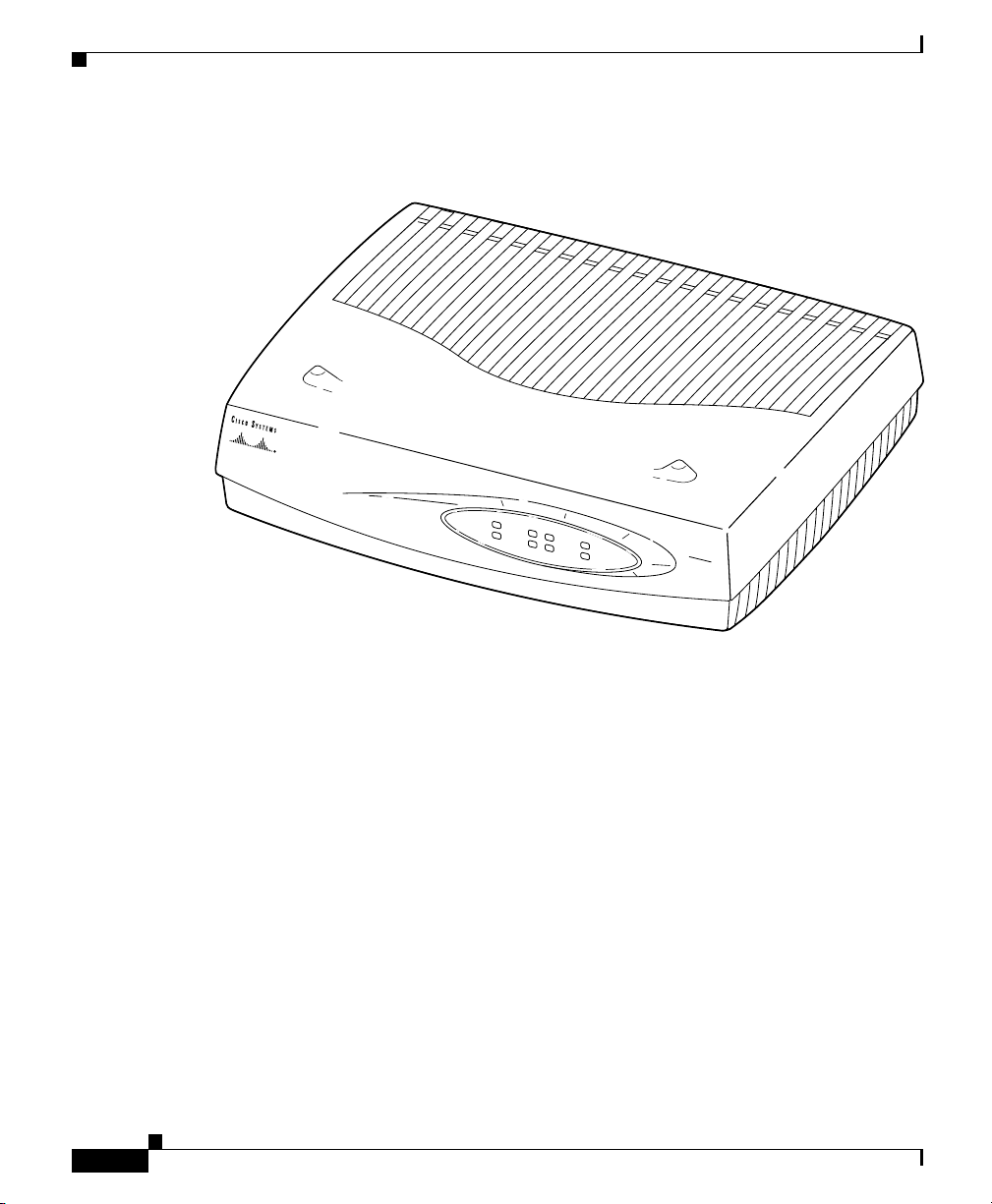
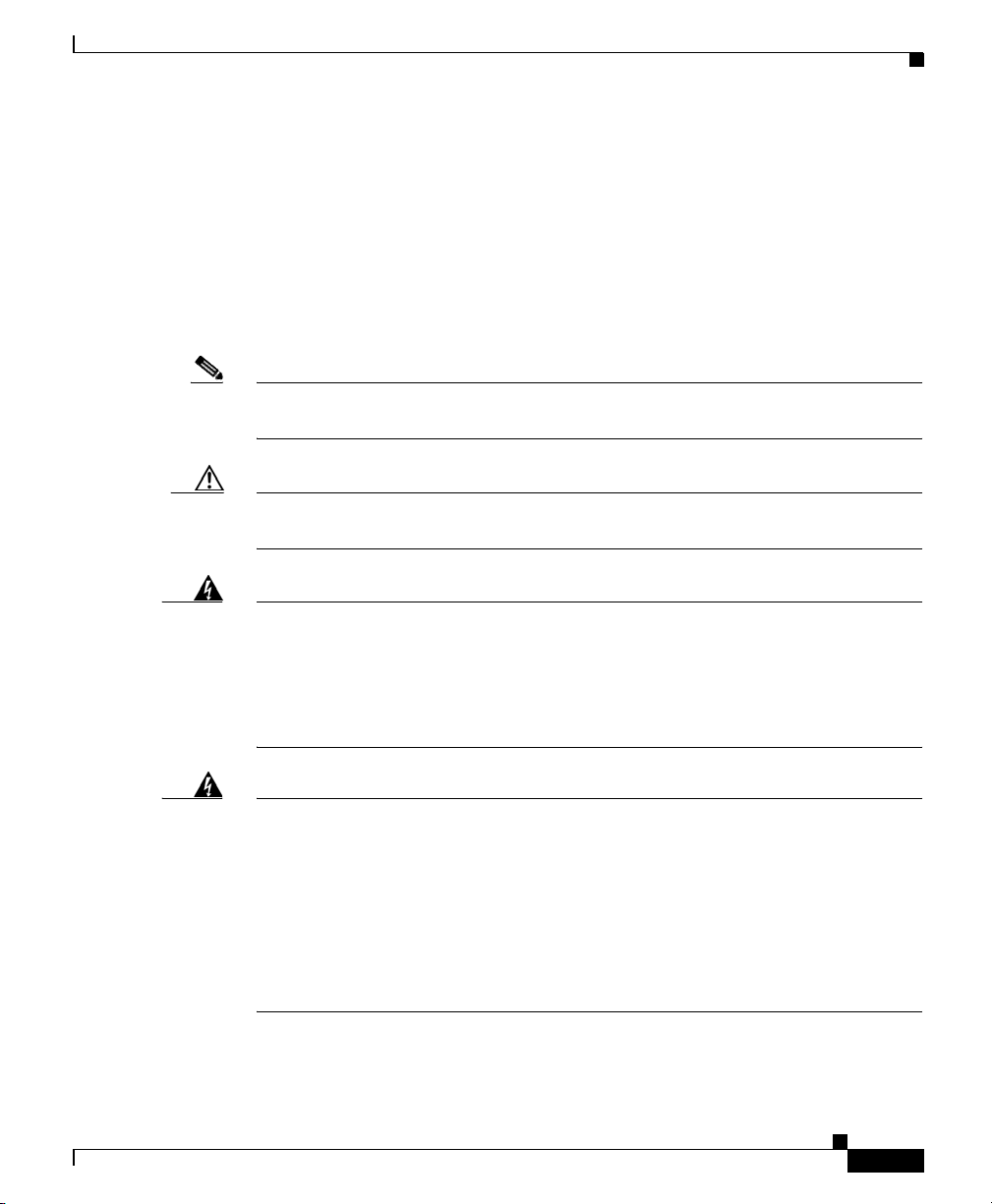
Figure 1-1 Cisco 1700 Router
PW
R
W
IC
ACT/CH0
OK
ACT/CH1
Chapter 1 Cisco 1700 Router Overview
12154
0
W
IC1
ACT/CH0
ETH
ACT
ACT/CH1
COL
Cisco
1700
SERIES
ROUTER
1-2
Cisco 1700 Router Hardware Installation Guide
78-5405-03
Page 23

Chapter 1 Cisco 1700 Router Overview
Key Features
The Cisco 1700 router is a small, modular desktop router that links small- to
medium-size remote Ethernet and FastEthernet LANs over one to four WAN
connections to regional and central offices. lists the router key features.
Figure 1-2 Key Features
Feature Description
One FastEthernet (10/100BaseTX) port • Operates in full- or half-duplex mode (with manual override
available).
• Supports autosensing for 10- or 100-Mbps operation.
Two Cisco WAN interface card slots • Supports a combination of any two of the following WAN interface
cards: ISDN BRI, 56-kbps DSU/CSU, FT1/T1 DSU/CSU, high-speed
serial, and dual-serial.
• The WAN interface configuration can be changed as your network
requirements change.
Console port Supports router configuration and management with a
directly-connected terminal or PC. Supports up to 115.2 kbps.
Auxiliary port Supports modem connection to the router, which can be configured and
managed from a remote location. Supports up to 115.2 kbps.
SNMP support Router can be managed over a network using Simple Network
Management Protocol (SNMP).
AutoInstall support Configuration files can be easily downloaded to the router over a WAN
connection.
Kensington security slot Router can be secured to a desktop or other surface using Kensington
lockdown equipment.
Cisco ConfigMaker support You can set up networks that include the Cisco 1700 router using the
Cisco ConfigMaker application, a wizards-based software tool that helps
you easily configure and address Cisco routers, access servers, hubs,
switches, and networks.
Compatible with Cisco Networked
Office stack
Support for Cisco IOS software features Supports IP, IPX, AppleTalk, IBM, Open Shortest Path First (OSPF),
Can be stacked and operated with other members of the
Cisco Networked Office stack product line.
NetWare Link Services Protocol (NLSP), Resource Reservation Protocol
(RSVP), encryption, network address translation, and the Cisco IOS
Firewall Feature Set.
78-5405-03
Cisco 1700 Router Hardware Installation Guide
1-3
Page 24
Rear-Panel Ports and LEDs
This section describes the router rear panel ports and LEDs, which are shown in
Figure 1-3 and described in Tab le 1-1 and Table 1- 2 .
Figure 1-3 Rear-Panel Ports and LEDs
Kensington-compatible
locking socket
WIC 0 slot WIC 1 slot
Console port
Chapter 1 Cisco 1700 Router Overview
Power switch
CONSOLE
Cisco 1720
WIC 0
OK LED
FDX LNK100WIC0OK WIC1OK
10/100 ETHERNET
10/100-Mbps
Ethernet port
FDX/100/LNK LEDs
AUX
Auxiliary port
Table 1-1 Rear-Panel Connectors
Connector/Slot Label/Color Description
Ethernet port 10/100
ETHERNET
(yellow)
Connects the router to the local Ethernet network through this
port. This port autosenses the speed (10 Mbps or 100 Mbps) and
duplex mode (full- or half-) of the device to which it is connected
and then operates at the same speed and in the same duplex
mode.
Auxiliary port AUX
(black)
Console port CONSOLE
(blue)
WAN interface card slot
No label Supports one Cisco WAN interface card. For detailed
(WICØ)
Connects to a modem for remote configuration with Cisco IOS
software.
Connects to a terminal or PC for local configuration using
Cisco IOS software.
information, refer to the Cisco WAN Interface Cards Hardware
Installation Guide that comes with every card.
ALLPRD
TD
SEE MANUAL BEFORE INSTALLATION
CD
WIC 1
OK LED
DSU
56K
+5, +12, -12 VDC
12156
Powe r
socket
1-4
Cisco 1700 Router Hardware Installation Guide
78-5405-03
Page 25

Chapter 1 Cisco 1700 Router Overview
Table 1-1 Rear-Panel Connectors (Continued)
Connector/Slot Label/Color Description
WAN interface card slot
(WIC1)
Power socket +5, +12, -12 VDC Connects the router to the external power supply.
Table 1-2 Rear-Panel LEDs
LED Label Color Description
WICØ OK Green On when a WAN interface card is correctly inserted in the card slot.
FDX Green On solid—Ethernet port is operating in full-duplex mode.
100 Green On solid—Ethernet port is operating at 100 Mbps.
LNK Green On when the Ethernet link is up.
WIC1 OK Green On when a WAN interface card is correctly inserted in the card slot.
No label Supports one Cisco WAN interface card. For detailed
information, refer to the Cisco WAN Interface Cards Hardware
Installation Guide that comes with every card.
Use the rear-panel LEDs during router installation to confirm that you have
correctly connected all cables to the router.
Off—Ethernet port is operating in half-duplex mode.
Off—Ethernet port is operating at 10 Mbps.
78-5405-03
Cisco 1700 Router Hardware Installation Guide
1-5
Page 26
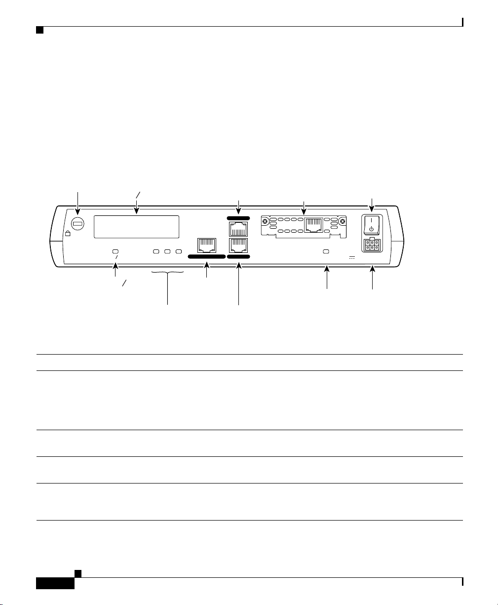
Front-Panel LEDs
Use the router front-panel LEDs to determine network activity and status on the
Ethernet port and on the WAN interface card ports. The front-panel LEDs are
illustrated in Figure 1-4 and described in Table 1-3 .
Figure 1-4 Front-Panel LEDs
Chapter 1 Cisco 1700 Router Overview
PWR
OK
WIC0
ACT/CH0
ACT/CH1
WIC1
ACT/CH0
ACT/CH1
ETH
ACT
COL
Table 1-3 Front-Panel LEDs
LED Label Color Description
PWR Green On means that DC power is being supplied to the router.
OK Green On means that the router has successfully booted up and the software is functional.
This LED blinks during the power-on self-test (POST).
Refer to Tab le 3- 1 in the “Troubleshooting” chapter for information on how to use
this LED for router diagnostics.
ETH
ACT Green Blinks when there is network activity on the Ethernet port.
COL Yellow Blinks when there are packet collisions on the local Ethernet network.
12155
1-6
Cisco 1700 Router Hardware Installation Guide
78-5405-03
Page 27

Chapter 1 Cisco 1700 Router Overview
Table 1-3 Front-Panel LEDs (Continued)
LED Label Color Description
WICØ
ACT/CHØ Green Serial and DSU/CSU cards—Blinks when data is being sent to or received from
the port on the card in the WICØ slot.
ISDN cards—On solid when the first ISDN B channel is up for the card in the
WICØ slot.
2-port serial cards—Blinks when there is data being sent to or received from the
first port on the 2-port card in the WICØ slot.
ACT/CH1 Green Serial and CSU/DSU cards—Remains off.
ISDN cards—On solid when the second ISDN B channel is up for the card in the
WICØ slot
2-port serial cards—Blinks when there is data being sent to or received from the
second port on the 2-port card in the WICØ slot.
WIC1
ACT/CHØ Green Serial and DSU/CSU cards—Blinks when data is being sent to or received from
the port on the card in the WIC1 slot.
ISDN cards—On solid when the first ISDN B channel is up for the card in the
WIC1 slot.
2-port serial cards—Blinks when there is data being sent to or received from the
first port on the 2-port card in the WIC1 slot.
ACT/CH1 Green Serial and DSU/CSU cards—Remains off.
ISDN cards—On solid when the second ISDN B channel is up for the card in the
WIC1 slot.
2-port serial cards—Blinks when there is data being sent to or received from the
second port on the 2-port card in the WIC1 slot.
78-5405-03
Cisco 1700 Router Hardware Installation Guide
1-7
Page 28

Router Memory
This section describes the types of memory stored in the router and how to find
out how much of each type of memory is stored in the router.
For instruction on how to upgrade memory in the router, refer to the “Installing
and Upgrading Router Memory” appendix later in this guide.
Types of Memory
The Cisco 1700 router has the following types of memory:
• Dynamic random-access memory (DRAM)—This is the main storage
memory for the router. DRAM is also called working storage and contains the
dynamic configuration information. The Cisco 1700 router stores a working
copy of Cisco IOS software, dynamic configuration information, and routing
table information in DRAM.
• Nonvolatile random-access memory (NVRAM)—This type of memory
contains a backup copy of your configuration. If the power is lost or the router
is turned off, this backup copy enables the router to return to operation
without reconfiguration.
• Flash memory—This special kind of erasable, programmable memory
contains a copy of the Cisco IOS software. The Flash memory structure can
store multiple copies of the Cisco IOS software. You can load a new level of
the operating system in every router in your network and then, when
convenient, upgrade the whole network to the new level. The Flash memory
on the Cisco 1700 router is stored on mini-Flash modules.
Chapter 1 Cisco 1700 Router Overview
1-8
Cisco 1700 Router Hardware Installation Guide
78-5405-03
Page 29

Chapter 1 Cisco 1700 Router Overview
Amounts of Memory
Use the show version command to view the amount of DRAM, NVRAM, and
Flash memory stored in your router. The following example of the show version
command output in bold text displays the amount of memory stored in this router.
1700# show version
Cisco Internetwork Operating System Software
IOS (tm) C1700 Software (C1700-Y-M), Version
12.X(XX)T
[cisco-ferrari2 121]
Copyright (c) 1986-1998 by cisco Systems, Inc.
Compiled Tue 26-May-98 19:58 by . . .
.
.
.
cisco 1700 (MPC860) processor (revision 0x00) with
12288K/4096K bytes of memory.
Processor board ID 0000 (1314672220), with hardware
revision 0000
M860 processor: part number 0, mask 32
Bridging software.
X.25 software, Version 3.0.0.
1 Serial network interface(s)
32K bytes of non-volatile configuration memory.
4096K bytes of processor board System flash
(Read/Write)
Configuration register is 0x0
.
.
.
78-5405-03
Cisco 1700 Router Hardware Installation Guide
1-9
Page 30

Unpacking the Router
Table 1-4 lists the items that come with your router. All these items are in the
accessory kit that is inside the box that your router came in.
Table 1-4 Router Box Contents
Power cord (black)
•
• Power supply
• DB-25 to DB-9 adapter
• Console cable, RJ-45 to DB-9 (light blue)
• Product documentation
Additional Required Equipment
Depending on your local network and which Cisco WAN interface cards you
install in your router, you will require other items, listed in Tab le 1-5, to complete
your router installation.
Chapter 1 Cisco 1700 Router Overview
1-10
Table 1-5 Additional Required Equipment
Equipment When You Use It
Ethernet hub A hub connects pieces of network equipment (including the
Cisco 1700 router) to create a network. You can use a 10-, 100-,
or 10/100-Mbps hub with the Cisco 1700 router.
Ethernet switch A switch connects pieces of network equipment (including the
Cisco 1700 router) to create a network. You can use a 10-, 100-,
or 10/100-Mbps switch with the Cisco 1700 router.
Phillips screwdriver Although the WAN interface cards use thumbscrews, you might
need a Phillips screwdriver to loosen the WAN interface card
slot cover.
Cisco 1700 Router Hardware Installation Guide
78-5405-03
Page 31

Chapter 1 Cisco 1700 Router Overview
Equipment When You Use It
Cisco WAN interface card In order to make a WAN connection, the Cisco 1700 router must
Straight-through
RJ-45-to-RJ-45 cable
Serial cable This cable connects a serial card to serial services. You must
NT1 Some ISDN service providers require a Network Termination 1
Asynchronous modem Connect a modem to the AUX port on the router when you want
have a supported WAN interface card installed. The router
supports up to two cards. You can order the cards when ordering
the router, and they will be installed for you. You can order the
cards separately, after receiving the router, and install them
yourself.
This cable connects the router to the Ethernet LAN and the
WAN interface cards to various WAN services, including ISDN,
T1/FT1, and 56-kbps services. You will need one cable for each
connection that requires this cable type.
order this cable from Cisco. For detailed information about
serial cable types, refer to the Cisco WAN Interface Cards
Hardware Installation Guide that comes with every card.
device to connect an ISDN S/T port to the ISDN line.
to configure the router from a remote location.
78-5405-03
Cisco 1700 Router Hardware Installation Guide
1-11
Page 32

Chapter 1 Cisco 1700 Router Overview
1-12
Cisco 1700 Router Hardware Installation Guide
78-5405-03
Page 33

Installing the Cisco 1700 Router
This chapter of installation procedures for the Cisco 1700 router includes the
following sections:
• Before Installing the Router
• Connecting the Router to Your Local Network
• Installing WAN Interface Cards
• Connecting Power to the Router
• Verifying Your Installation
• Optional Installation Steps
Before Installing the Router
CHA P TER
2
78-5405-03
The Cisco 1700 router is shipped ready for desktop mounting. Before making the
power and network connections, simply set the router on a desktop, shelf, or other
flat surface.
Note For instructions on wall-mounting the router, refer to the “Wall-Mounting”
section later in this chapter.
Be sure to read the safety information in the Regulatory Compliance and Safety
Information for the Cisco 1700 document that came with your router.
Cisco 1700 Router Hardware Installation Guide
2-1
Page 34

Chapter 2 Installing the Cisco 1700 Router
Warning
Warning
Caution Do not place anything on top of the router that weighs more than 10 pounds
Read the installation instructions before you connect the system to its power
source.
Do not work on the system or connect or disconnect cables during periods of
lightning activity.
(4.5 kgs). Excessive weight on top of the router could damage the chassis.
Connecting the Router to Your Local Network
The Cisco 1700 router is connected to your local Ethernet network through the
yellow 10/100 Ethernet port. You must provide the following items for this
connection:
• A straight-through, RJ-45-to-RJ-45, Ethernet cable
• A 10/100-Mbps Ethernet hub or switch
Warning
The ports labeled 10/100 ETHERNET and CONSOLE are safety extra-low voltage
(SELV) circuits. SELV circuits should only be connected to other SELV circuits.
Because BRI circuits are treated like telephone-network voltage, avoid
connecting the SELV circuits to the telephone network voltage (TNV) circuits.
(To see translated versions of this warning, refer to the Regulatory Compliance
and Safety Information for the Cisco 1700 document that came with the router.)
2-2
Caution Always connect the Ethernet cable to the yellow ports on the router. Do not
connect the cable to an ISDN S/T or U port (on a WAN interface card) or to an
NT1 that is connected to a WAN interface card. Accidently connecting the cable
to the wrong port can damage your router.
Cisco 1700 Router Hardware Installation Guide
78-5405-03
Page 35

Chapter 2 Installing the Cisco 1700 Router
Follow these steps to connect the router to the local network:
Figure 2-1 Connecting the Router to the Local Network
Cisco 1720
WIC0OK
FDX
100
Ethernet port
Step 1 Connect one end of the cable to the yellow Ethernet port
(labeled 10/100 ETHERNET).
Step 2 Connect the other end of the cable to a network port on
the hub or switch.
CO
10/100 ETHERNET
NSOLE
TD
RD
LP
AL
S
E
E
M
A
N
U
A
L
B
E
FO
CD
R
E
IN
S
T
A
L
DSU
L
AUX
A
T
IO
WIC1OK
N
56K
+
5
, +
1
2
, -1
2
V
D
C
Ethernet hub or switch
(10, 100, or 10/100 Mbps)
LNK
10/100
78-5405-03
Straight-through
Ethernet cable
AUI
8
7
6
5
4
3
2
1
12157
Cisco 1700 Router Hardware Installation Guide
2-3
Page 36

Installing WAN Interface Cards
The Cisco 1700 router supports one or two Cisco WAN interface cards. Each card
has one or two WAN ports. This section describes the general procedure for
installing a card in the Cisco 1700 router.
Note For details on specific WAN interface cards, how to connect the card to the WAN
line, and how to configure the interface with Cisco IOS software, refer to the
Cisco WAN Interface Cards Hardware Installation Guide that came with the
card(s).
Safety Information
This section lists safety warnings that you should be aware of before installing
WAN interface cards in the router.
Chapter 2 Installing the Cisco 1700 Router
2-4
Warning
Warning
Warning
Cisco 1700 Router Hardware Installation Guide
Only trained and qualified personnel should be allowed to install or replace this
equipment. (To see translated versions of this warning, refer to the Regulatory
Compliance and Safety Information for the Cisco 1700 document that came with
the router.)
Before working on equipment that is connected to power lines, remove jewelry
(including rings, necklaces, and watches). Metal objects will heat up when
connected to power and ground and can cause serious burns or weld the metal
object to the terminals. (To see translated versions of this warning, refer to the
Regulatory Compliance and Safety Information for the Cisco 1700 document that
came with the router.)
Before opening the chassis, disconnect the telephone-network cables (from the
card) to avoid contact with the telephone-network voltages. (To see translated
versions of this warning, refer to the Regulatory Compliance and Safety
Information for the Cisco 1700 document that came with the router.)
78-5405-03
Page 37

Chapter 2 Installing the Cisco 1700 Router
Warning
Caution Do not connect a WAN cable to the card until you have completed the installation
Do not work on the system or connect or disconnect cables during periods of
lightning activity. (To see translated versions of this warning, refer to the
Regulatory Compliance and Safety Information for the Cisco 1700 document that
came with the router.)
procedure.
Installing a WAN Interface Card
This section describes how to install WAN interface cards in the router.
Installing the Cards in Correct Sequence
The Cisco 1700 router discovers interfaces on WAN interface cards installed in
the WIC0 slot before it discovers those installed in the WIC1 slot. This can affect
your router configuration. This section describes how to ensure that your existing
router configuration is not affected when you install WAN interface cards.
If you are installing a WAN interface card in the router for the first time, install
the card in the WIC0 slot to ensure that your software configuration will not be
affected if you install a second card at a later time.
If you are installing a second WAN interface card in a Cisco 1720 that has a card
installed in the WIC1 slot, follow this general procedure to prevent having to
reconfigure your router:
78-5405-03
Caution Read the instructions in the following section, “Installing the Cards,” before
installing the cards.
Step 1 Remove the installed card from the WIC1 slot.
Step 2 Reinstall the card (removed in Step 1) in the WIC0 slot.
Step 3 Install the new card in the WIC1 slot.
Cisco 1700 Router Hardware Installation Guide
2-5
Page 38

Installing the Cards
Follow these steps to install the card in a Cisco 1700 router:
Figure 2-2 Removing the WAN Interface Card-Slot Cover
Chapter 2 Installing the Cisco 1700 Router
Step 1 Make sure that the power switch is set to the STANDBY
position ( ) and that the power cable is not connected
to the power socket on the rear panel.
Step 2 Loosen the thumbscrews on the WAN interface card-slot
cover on the rear panel, as shown in Figure 2-2.
You should be able to loosen the screws using your
fingers; however, if the screws are very tight, you might
need to use a Phillips screwdriver.
2-6
Cisco 1720
WIC0OK
10/100 ETHERN
CONSOLE
ET
FDX
100
LNK
WAN interface card slot cover
Step 3
Step 4 Hold the WAN interface card by the edges on either side
Cisco 1700 Router Hardware Installation Guide
AUX
WIC1OK
+5, +12, -12 VDC
Remove the metal plate that covers the card slot.
of the card front panel, and line up the card edges with
the guides inside the card slot, as shown in Figure 2-3.
78-5405-03
12158
Page 39

Chapter 2 Installing the Cisco 1700 Router
Figure 2-3 Inserting a WAN Interface Card in the Router
1720
WIC0OK
Step 5 Insert the card in the slot and gently push it into the
router until the front panel of the card is flush with the
rear panel of the router.
Step 6 Tighten the screws.
10/100 ETHERNET
CONSOLE
AUX
WIC1OK
+5, +12, -12 VDC
FDX
LNK100
12159
78-5405-03
TD
RD
LP
AL
S
EE
M
A
NU
A
L B
E
FO
CD
RE
IN
STA
LLA
TION
WAN interface card
Guides
D
S
U
56K
Cisco 1700 Router Hardware Installation Guide
2-7
Page 40

Connecting Power to the Router
Read the following warnings before connecting the router to power.
Chapter 2 Installing the Cisco 1700 Router
Warning
Warning
Warning
The power supply is designed to work with TN power systems.
This product relies on the building’s installation for short-circuit (overcurrent)
protection. Ensure that a fuse or circuit breaker no larger than 120VAC, 15AU.S.
(240VAC, 16A international) is used on the phase conductors (all
current-carrying conductors).
This equipment is intended to be grounded. Ensure that the host is connected to
earth ground during normal use.
Take the following steps to connect power to the router and to turn the router on:
Step 1 Connect the attached power-supply cord to the power
socket (labeled +5,+12,-12 VDC) on the router rear
panel.
Step 2 Connect one end of the separate power cord to the socket
on the power supply.
Step 3 Connect the other end of the separate power cord to a
power outlet.
Step 4 Press the router power switch to ON ( | ).
2-8
Step 5 Confirm that the router has power by checking that the
PWR LED on the front panel is on.
Cisco 1700 Router Hardware Installation Guide
78-5405-03
Page 41

Chapter 2 Installing the Cisco 1700 Router
Figure 2-4 Connecting the Power Supply
Cisco 1720
WIC0OK
12162
C
O
NSO
10/100 ETHERNET
LE
TD
RD
LP
AL
S
E
E
M
A
N
U
A
L
B
E
F
CD
O
R
E
IN
S
T
A
L
AU
X
D
L
S
A
U
T
IO
N
56K
WIC1OK
+5, +12, -12 VDC
Power socket
FDX
100
LNK
78-5405-03
Cisco 1700 Router Hardware Installation Guide
2-9
Page 42

Verifying Your Installation
You can verify that you have correctly installed the router by checking the
following LEDs:
• PWR (front panel)—On when power is being supplied to the router.
• OK (front panel)—On when the router software is loaded and functional.
Blinking means that the router is performing a power-on self-test (POST).
• WICØ/WIC1 OK (rear panel)—On when a WAN interface card is correctly
installed in the corresponding WAN interface card slot.
• ETH ACT (front panel)—Blinking when there is network traffic on the local
Ethernet LAN.
• WICØACT or WIC1 ACT (front panel)—Varies depending on the WAN
interface card installed. Refer to Table 1-3 in the “Cisco 1700 Router
Overview” chapter.
• LNK (rear panel)—On when the router is correctly connected to the local
Ethernet LAN through the 10/100 ETHERNET port.
Chapter 2 Installing the Cisco 1700 Router
2-10
Cisco 1700 Router Hardware Installation Guide
78-5405-03
Page 43

Chapter 2 Installing the Cisco 1700 Router
Optional Installation Steps
This section describes some installation steps that you might or might not use,
depending on your site and how you are configuring the router. This chapter
describes the following procedures:
• Connecting a PC
• Connecting a Modem
• Wall-Mounting
Connecting a PC
If you want to configure the router using the Cisco IOS command-line interface,
you must connect the router console port to a terminal or PC. The cable and
adapter required for this connection are included with the router.
To configure the router with a PC, the PC must have some type of terminal
emulation software installed. The software should be configured with the
following parameters: 9600 baud, 8 data bits, no parity bits, 1 stop bit. Refer to
the Cisco 1700 Router Software Configuration Guide that came with your router
for detailed information about configuring the router using Cisco IOS software.
Follow these steps to connect the router to a terminal or PC:
78-5405-03
Step 1 Connect the blue console cable to the blue CONSOLE
port on the router, as shown in Figure 2-5.
Step 2 Use the correct adapter to connect the other end of the
cable to the terminal or PC. If your terminal or PC has a
console port that does not fit the adapter included with
the router, you must provide the correct adapter for that
port.
Cisco 1700 Router Hardware Installation Guide
2-11
Page 44

Chapter 2 Installing the Cisco 1700 Router
Figure 2-5 Connecting the Console Cable to the Router
1720
WIC0OK
e console cable
FDX
100
LNK
10/100 ETH
CONSOLE
AUX
Console port
TD
RD
LP
AL
S
E
E
M
A
N
U
A
L
B
E
F
CD
O
R
E
IN
S
T
A
L
D
L
S
A
U
T
IO
N
56
K
WIC1OK
+5, +12, -12 V
D
C
12160
Connecting a Modem
When a modem is connected to the auxiliary port, a remote user can dial into the
router and configure it. You can use the blue console cable that came in the
accessory kit or (if you are using the blue cable with the console port) you can use
any crossover RJ-45-to-RJ-45 cable.
Take the following steps to connect a modem to the router:
Cisco 1700 Router Hardware Installation Guide
2-12
To PC or terminal
Step 1 Connect one end of the cable to the black AUX port on
the router rear panel.
Step 2 Connect the gray adapter labeled MODEM to the other
end of the cable.
Step 3 Connect the DB-25 end of the adapter to the modem.
78-5405-03
Page 45

Chapter 2 Installing the Cisco 1700 Router
Figure 2-6 Connecting a Modem to the Router
20
W
IC0OK
FDX
LNK100
AUX port (RJ-45)
10/100 ETHERNET
CONSOLE
12161
TD
RD
LP
AL
S
E
E
M
A
N
U
A
L
B
E
F
CD
O
R
E
IN
S
T
A
L
DSU
L
A
AUX
T
IO
N
56K
W
IC1OK
+
5, +12, -12 V
D
C
78-5405-03
Modem
cable
DB-9-to-DB-25 adapter
EIA/TIA-232
Cisco 1700 Router Hardware Installation Guide
2-13
Page 46

Wall-Mounting
The Cisco 1700 router can be wall-mounted using two number 6, 3/4-inch screws
and the molded mounting brackets on the bottom of the hub. You must provide the
screws. We recommend using pan-head or round-head screws.
Figure 2-7 Wall-Mount Brackets—Bottom of Router
Chapter 2 Installing the Cisco 1700 Router
Front panel of router
Mounting
bracket
Bottom
of router
Mounting
bracket
3.75"
(9.52 cm)
To mount the router on a wall or other surface:
Step 1 Install the two screws 3.75 inches (9.52 centimeters)
horizontally apart on a wall or other vertical surface.
The screws should protrude 0.25 inches (0.64
centimeters) from the surface of the wall.
12016
2-14
Cisco 1700 Router Hardware Installation Guide
78-5405-03
Page 47

Chapter 2 Installing the Cisco 1700 Router
Caution If you install the screws in drywall, use hollow wall anchors (1/8 inch
by 5/16 inch) to secure the screws. If the screws are not properly anchored, the
strain of the cables connected to the router rear-panel connectors could pull the
router from the wall.
Step 2 Hang the router on the screws with either the left side or
right side mounting brackets so that:
• The LEDs are visible to the user—The LEDs
indicate the router operating status, so the LEDs
should be easily visible.
• The power supply does not hang from its cable—If
the power supply is not supported, it might
disconnect from the cable that connects it to the
router.
78-5405-03
Cisco 1700 Router Hardware Installation Guide
2-15
Page 48

Chapter 2 Installing the Cisco 1700 Router
2-16
Cisco 1700 Router Hardware Installation Guide
78-5405-03
Page 49

CHA P TER
Troubleshooting
Use the information in this chapter to help isolate problems you might encounter
with the Cisco 1700 router or to rule out the router as the source of the problem.
This chapter contains the following sections:
• Contacting Cisco or Your Reseller
• Recovering a Lost Password
• Problem Solving
• Troubleshooting ISDN
Contacting Cisco or Your Reseller
If you cannot locate the source of a problem, contact your local reseller for advice.
Before you call, you should have the following information ready:
• Chassis type and serial number
• Maintenance agreement or warranty information
3
78-5405-03
• Type and version number of the Cisco IOS installed on your router
• Date you received the router
• Brief description of the problem
• Brief description of the steps you have taken to isolate the problem
• Output from the show tech-support command
Cisco 1700 Router Hardware Installation Guide
3-1
Page 50

Recovering a Lost Password
This section describes how to recover a lost enable or enable secret password. The
process of recovering a password consists of the following major steps:
• Change the Configuration Register
• Reset the Router
• Reset the Password (for lost enable secret passwords only)
• Reset the Configuration Register Value
Note See the “Hot Tips” section on Cisco Connection Online (CCO) for additional
information on replacing enable secret passwords.
Change the Configuration Register
Step 1 Connect an ASCII terminal or a PC running a
terminal-emulation program to the CONSOLE port on
the rear panel of the router. Refer to the section
“Connecting a PC” in the “Installing the Cisco 1700
Router” chapter.
Chapter 3 Troubleshooting
3-2
Step 2 Configure the terminal to operate at 9600 baud, 8 data
bits, no parity, and 1 stop bit.
Step 3 Reboot the router by pressing the power switch to the
OFF position, then to the ON ( | ) position.
Cisco 1700 Router Hardware Installation Guide
78-5405-03
Page 51

Chapter 3 Troubleshooting
Step 4 At the user EXEC prompt (Router>), enter the show
version command to display the existing configuration
register value (shown in bold at the bottom of this
example output):
Router> show version
Cisco Internetwork Operating System Software
IOS (tm) C1700 Software (C1700-BNOR2SY56I-M),
Experimental Version 12.0(19980725:020859)
[aiyagari-devtest_0724 100]
Copyright (c) 1986-1998 by cisco Systems, Inc.
Compiled Fri 24-Jul-98 19:09 by aiyagari
Image text-base: 0x80008084, data-base:
0x8084356C
ROM: System Bootstrap, Version
11.3(19980612:045022)
[rochen-v35-rommon-release-devtest 101],
INTERIM SOFTWARE
Router uptime is 15 minutes
System restarted by power-on
Running default software
cisco 1720 (MPC860) processor (revision 0x00)
with 22119K/2457K bytes of memory.
Processor board ID 0000 (1314672220), with
hardware revision 0000
M860 processor: part number 0, mask 32
Bridging software.
X.25 software, Version 3.0.0.
1 FastEthernet/IEEE 802.3 interface(s)
1 Serial(sync/async) network interface(s)
32K bytes of non-volatile configuration
memory.
4096K bytes of processor board System flash
(Read/Write)
Configuration register is 0x0
78-5405-03
Step 5 Record the setting of the configuration register. It is
usually 0x2102 or 0x102.
Step 6 Record the break setting.
• Break enabled—bit 8 is set to 0.
• Break disabled (default setting)—bit 8 is set to 1.
Cisco 1700 Router Hardware Installation Guide
3-3
Page 52

Note To enable break, enter the config-register 0x01 EXEC command.
Reset the Router
Note Some terminal keyboards have a key labeled Break. If your keyboard does not
have a Break key, refer to the documentation that came with the terminal for
instructions on how to send a break. To send a break in Windows HyperTerminal,
enter Ctrl-Break.
Chapter 3 Troubleshooting
Step 1 Do one of the following:
• If break is enabled, go to Step 2.
• If break is disabled, turn the router OFF, wait
5 seconds, and turn it ON again. Within 60 seconds,
press the Break key. The terminal displays the
ROM monitor prompt. Go to Step 3.
3-4
Step 2 Send a break. The terminal displays the following
prompt:
rommon 2>
Step 3 Enter confreg 0x142 as follows to reset the
configuration register:
rommon 2> confreg 0x142
Step 4 Initialize the router by entering the reset command:
rommon 2> reset
The router resets, and the configuration register is set to
0x142. The router boots the system image in Flash
memory, and displays the following:
--- System Configuration Dialog ---
Step 5 Enter no in response to the prompts until the following
message is displayed:
Cisco 1700 Router Hardware Installation Guide
78-5405-03
Page 53

Chapter 3 Troubleshooting
Press RETURN to get started!
Step 6 Press Return. The following prompt appears:
Router>
Step 7 Enter the enable command to enter privileged EXEC
mode. Configuration changes can be made only in this
mode:
Router> enable
The prompt changes to the privileged EXEC prompt:
Router#
Step 8 Enter the show startup-config command to display an
enable password in the configuration file:
Router# show startup-config
If you are recovering an enable password, skip the
following “Reset the Password” section and complete
the password recovery process by performing the steps
in the next section, “Reset the Configuration Register
Va lu e .”
Reset the Password
78-5405-03
If you are recovering an enable secret password, it is not
displayed in the show startup-config command output.
Complete the password recovery process by performing
the steps in the following “Reset the Password” section.
Step 1 Enter the configure terminal command to enter
configuration mode:
Router# configure terminal
Step 2 Enter the enable secret command to reset the enable
secret password in the router:
Router(config)# enable secret gobbledegook
Cisco 1700 Router Hardware Installation Guide
3-5
Page 54

Step 3 Enter the config-register command and the original
configuration register value that you recorded in Step 5.
Step 4 Press Ctrl-Z to exit configuration mode.
Router(config)# Ctrl-Z
Step 5 Save your configuration changes:
Router# copy running-config startup-config
Reset the Configuration Register Value
Once you have recovered or reconfigured a password
Step 1 Enter the configure terminal command to enter
configuration mode:
Router# configure terminal
Step 2 Enter the config-register command and the original
configuration register value that you recorded in Step 5.
Chapter 3 Troubleshooting
Problem Solving
The key to problem solving is to isolate the problem to a specific subsystem by
comparing what the router is doing to what it should be doing.
When problem solving, consider the following subsystems of the router:
• WAN interface cards—Refer to the LEDs on the cards and the LEDs on the
router front panel to help identify a failure. For more information on WAN
interface cards, refer to the Cisco WAN Interface Cards Hardware
Installation Guide that comes with each card.
• Cables—Check all the external cables that connect the router to the network.
Cisco 1700 Router Hardware Installation Guide
3-6
Step 3 Press Ctrl-Z to exit configuration mode:
Router(config)# Ctrl-Z
Step 4 Reboot the router, and enter the recovered password.
78-5405-03
Page 55

Chapter 3 Troubleshooting
• Power system—Check the external power source, power cable, router power
supply, and circuit breaker. Check for inadequate ventilation or air circulation
that might cause overheating.
• ISDN configuration—Consider ISDN-specific hardware and software
configurations (ISDN BRI WAN interface cards only).
OK LED Diagnostics
Use the front-panel OK LED to determine any problems with the router. When the
router first boots up, it performs a power-on self-test (POST). If the router detects
a problem during the POST, the OK LED blinks in a different patterns (described
in Table 3-1) depending on the problem. A pattern consists of a specific number
of blinks that is repeated until the router is turned off. If the router experiences
any of these problems, contact your Cisco reseller.
Number of Blinks Meaning
2 The 860T dual-port random-access memory (DPRAM) failed.
3 The parameter RAM area of the 860T DPRAM failed.
4 The 860T system protection control register has a write failure.
5 The router cannot detect the dynamic random-access memory (DRAM).
6 The user programmable machine has a write failure.
9 The router DRAM failed.
Table 3-1 OK LED Blinking Patterns
Troubleshooting WAN Interface Cards and Cables
Use the show diag command to help determine problems with a card. Table 3-2
lists problems that could occur with the WAN interface cards and the possible
causes of these problems.
Cisco 1700 Router Hardware Installation Guide
78-5405-03
3-7
Page 56

Table 3-2 Troubleshooting WAN Interface Cards
Symptom Possible Cause(s)
Router does not recognize WAN
interface card
Router recognizes the WAN interface
card(s), but the card port(s) do not
initialize.
Router does not boot properly or
continuously or intermittently
reboots.
• Confirm that the Cisco IOS software version installed in the router supports
the WAN interface card. The Cisco WAN Interface Cards Hardware
Installation Guide lists the software requirements for each card.
• Make sure that the card is correctly installed in the router. Refer to the
“Installing WAN Interface Cards” section in the “Installing the Cisco 1700
Router” chapter.
•Use the show diag command to display information about the card:
Router# show diag
Slot 0:
C1700 1FE Mainboard port adapter, 2 ports
Port adapter is analyzed
Port adapter insertion time unknown
Hardware revision 0.0 Board revision UNKNOWN
Serial number 1314672220 Part number 00-0000-00
Test history 0x0 RMA number 00-00-00
EEPROM format version 1
EEPROM contents (hex):
0x20: 01 B2 00 00 4E 5C 4E 5C 00 00 00 00 00 00 00 00
0x30: 00 00 00 04 00 00 00 00 00 00 00 00 00 00 00 00
WIC Slot 0:
Serial 1T WAN daughter card
Hardware revision 1.1 Board revision E0
Serial number 7131279 Part number 73-1775-02
Test history 0x0 RMA number 00-00-00
Connector type Wan Module
EEPROM format version 1
EEPROM contents (hex):
0x20: 01 02 01 01 00 6C D0 8F 49 06 EF 02 00 00 00 00
0x30: 70 00 00 00 98 01 23 01 FF FF FF FF FF FF FF FF
• Make sure that the card is correctly installed in the router. Refer to the
“Installing WAN Interface Cards” section in the “Installing the Cisco 1700
Router” chapter.
• Check the external cable connections to make sure they are secure.
Make sure that the WAN interface card is correctly installed in the router.
Refer to the “Installing WAN Interface Cards” section in the “Installing the
Cisco 1700 Router” chapter.
Chapter 3 Troubleshooting
3-8
Cisco 1700 Router Hardware Installation Guide
78-5405-03
Page 57

Chapter 3 Troubleshooting
Table 3-2 Troubleshooting WAN Interface Cards (Continued)
Symptom Possible Cause(s)
Router boots, but the console screen
is frozen.
Router powers on and boots only
when a particular WAN interface
card is removed from the router.
Router powers on and boots only
when a particular cable is
disconnected.
• Make sure the console cable is securely connected to the router and to the
PC or terminal.
• Verify that the parameters for your terminal are set to the following:
— 9600 baud
— 8 data bits
— No parity generated or checked
— 1 stop bit
• Confirm that the Cisco IOS software version installed in the router supports
the WAN interface card. The Cisco WAN Interface Cards Hardware
Installation Guide lists the software requirements for each card.
• The router might be overheating. Contact your Cisco reseller.
There might be a problem with the WAN interface card or card cables.
Consult your Cisco reseller for warranty information.
Troubleshooting the Power System
If the router external power supply fails, it should be returned to your Cisco
reseller. Tabl e 3- 3 list symptoms and possible causes of power problems.
Table 3-3 Troubleshooting the Power System
Symptom Possible Cause(s)
Router shuts down after being on a short
time.
The router attempts to boot, but all LEDs
remain off.
The router is on, but the front-panel
PWR LED is off.
78-5405-03
• Make sure that the area in which the router is installed meets the
environmental site requirements in the “Technical Specifications”
appendix later in this guide and in the “Site Requirements” section in
the Regulatory Compliance and Safety Information for the Cisco 1700
that came with your router.
• If the front-panel PWR LED is not on, the power supply has failed.
The power supply has failed.
The power supply has failed.
Cisco 1700 Router Hardware Installation Guide
3-9
Page 58

Table 3-3 Troubleshooting the Power System
Symptom Possible Cause(s)
The front-panel PWR LED is on, the
front-panel OK LED is off, and the router
does not pass console or EIA data.
The power supply has failed.
Troubleshooting ISDN
Because ISDN uses many variables and supports many different configurations, it
sometimes can cause problems for the router. This section describes problems
related to the ISDN line that might occur.
Two commands are useful when troubleshooting ISDN:
• For routers with an ISDN S/T WAN interface card, enter the clear interface
command to terminate any active ISDN calls and to reset the ISDN BRI
interface. Do this for each ISDN port installed in the router:
Router# clear interface bri0
Router# clear interface bri1
• For routers with an ISDN U WAN interface card(s), use the clear controller
command to terminate any active ISDN calls, to reset the ISDN BRI
interface, and to reset the ISDN line between the router and the central office
switch. Do this for each ISDN port installed in the router:
Router# clear controller bri0
Router# clear controller bri1
Chapter 3 Troubleshooting
3-10
Table 3-4 lists troubleshooting methods for ISDN-specific problems that might
occur.
Cisco 1700 Router Hardware Installation Guide
78-5405-03
Page 59

Chapter 3 Troubleshooting
Table 3-4 Troubleshooting ISDN
WAN Interface
Card Symptom(s) Check the Following Possible Causes
ISDN S/T Router is on, but
OK LED on card
is off.
ISDN U Router is on, but
the NT1 LED on
card is off.
• Is the OK LED on the
router front panel on?
• Are all ISDN cables
properly connected?
• Is the NT1 on? • If no, the NT1 might be malfunctioning.
• Is the OK LED on? • If no, the router might be
• Are all ISDN cables
properly connected?
• Is the ISDN line connected
to the card ISDN U port?
• If no, the router might be
malfunctioning. Contact your Cisco
reseller.
• If yes, the ISDN line might be
malfunctioning. Check with your ISDN
service provider.
malfunctioning. Contact your Cisco
reseller.
• If yes, the ISDN line might be
malfunctioning. Check with your ISDN
service provider.
• If yes, the ISDN line might be
malfunctioning. Check with your ISDN
service provider.
78-5405-03
Cisco 1700 Router Hardware Installation Guide
3-11
Page 60

Table 3-4 Troubleshooting ISDN (Continued)
WAN Interface
Card Symptom(s) Check the Following Possible Causes
ISDN S/T
or
ISDN U
Card cannot
make a
connection to the
remote router.
Use show isdn status
command to check the
following:
• Does the current ISDN
switch type match actual
switch type being used?
• Is Layer 1 status
deactivated?
• If Layer 1 status is active,
does Layer 3 status say “2
Active Layer 3 calls”?
• If Layer 1 status is active,
does Layer 3 status say
“No Active Layer 3
call(s)”?
• If Layer 1 status is active,
does Layer 3 status say “1
Active Layer 3 call”?
•Use the isdn switch-type command to
configure correct switch type.
•Use the show controller bri0 command
to check for the messages CO
RUNNING LOOPBACK TESTS or CO
TESTING. If you receive these
messages, contact the service provider.
• Router might have called itself. Check
destination phone number configured
with the dialer map command or the
dialer string command.
• Check destination phone number and
make sure it matches the remote router
phone number. Check route to the
destination and make sure it matches
the remote router network address.
• Check router protocol configurations.
Chapter 3 Troubleshooting
3-12
Cisco 1700 Router Hardware Installation Guide
78-5405-03
Page 61

APPENDIX
Technical Specifications
Table A-1 lists hardware and operating specifications for the Cisco 1700 router.
Table A-1 Router Specifications
Description Specification
Console port RJ-45
Auxiliary port RJ-45
Ethernet port RJ-45
Dimensions
H x W x D 3.1 x 11.2 x 8.7 in. (7.85 x 28.4 x 22.1 cm)
Weight
With two WAN interface cards
Power supply
External
On-board
Power consumption 15W
Operating Specifications
Operating temperature
Storage temperature
Operating humidity
2.6 lbs (1.18 kg)
2.9 lbs ( 1.32 kg)
Universal AC/DC switching—Supplies +5V, +12V, and –12V
Supplies 3.3V and -5V
32 to 104° F (0° to 40°C)
-4 to 149° F (-20° to 65°C)
10 to 85%, noncondensing
A
78-5405-03
Cisco 1700 Router Hardware Installation Guide
A-1
Page 62

Appendix A Technical Specifications
A-2
Cisco 1700 Router Hardware Installation Guide
78-5405-03
Page 63

APPENDIX
B
Cabling Specifications
This appendix describes cables and cabling guidelines for the Cisco 1700 router
and contains the following sections:
• Ethernet Cables
• Ethernet Network Cabling Guidelines
• Console Cable and Adapters
Note For information about cables used with Cisco WAN interface cards, refer to the
Cisco WAN Interface Cards Hardware Installation Guide that comes with each of
the cards.
78-5405-03
Cisco 1700 Router Hardware Installation Guide
B-1
Page 64

Ethernet Cables
This section describes the Ethernet cables that are used to connect the router to
your local Ethernet network. A 10/100BaseTX router, like the Cisco 1700 router,
requires Category 5 unshielded twisted-pair (UTP) or shielded twisted-pair (STP)
cable.
Appendix B Cabling Specifications
Table B-1 Straight-Through Ethernet Cable
(RJ-45-to-RJ-45) Pinouts
RJ-45
1
Pin
1 TX+ —> 1
2 TX– —> 2
3RX+ <— 3
6RX– <— 6
1.Pins 4, 5, 7, and 8 are not used for signaling.
Signal Direction
RJ-45
Pin
B-2
Cisco 1700 Router Hardware Installation Guide
78-5405-03
Page 65

Appendix B Cabling Specifications
Ethernet Network Cabling Guidelines
Table B-2 describes some guidelines for creating Ethernet networks. Figures
might vary, depending on the manufacturer of the network equipment.
Table B-2 Ethernet Cabling Guidelines
Specification 10BaseT 100BaseTX
Maximum segment length 100 meters 100 meters
Maximum number of segments per
network
Maximum hop count
Maximum number of nodes per
segment
Cable type required UTP
1.Hop count = Routing metric used to measure the distance between a source and a destination.
1
5 • With Class I repeaters: 1
4 • With Class I repeaters: none
1024 1024
Category 3, 4, or 5
• With Class II repeaters: 2
• With Class II repeaters: 1
UTP Category 5 or STP
Console Cable and Adapters
A console cable kit is provided with your router. Use this kit when connecting
your router to a PC or terminal.
The console cable kit contains:
• RJ-45-to-RJ-45 console cable (blue)
• RJ-45-to-DB-9 adapter (gray)
Table B-3 describes the wiring for the console port, the console cable, and the
included adapters. This table also includes pinouts for an RJ-45-to-DB-25
adapter. Figure B-1 illustrates how to identify the console cable, which is also
referred to as a rollove r cable.
Cisco 1700 Router Hardware Installation Guide
78-5405-03
B-3
Page 66

Appendix B Cabling Specifications
Table B-3 Console Cable and Adapter Pinouts
Console
(DTE)
Console
Port Console Cable Adapter Adapter
Termin al
(DTE)
Signal RJ-45 Pin RJ-45 Pin DB-9 Pin DB-25 Pin Signal
RTS 1 8 8 5 CTS
DTR 2 7 6 6 DSR
TXD 3 6 2 3 RXD
GND 4 5 5 7 GND
GND 5 4 5 7 GND
RXD 6 3 3 2 TXD
DSR 7 2 4 20 DTR
CTS 8 1 7 4 RTS
Figure B-1 Identifying a Rollover Cable
Pin 1 on one connector and
pin 8 on the other connector
should be the same color.
Pin 8
B-4
H10632
Cisco 1700 Router Hardware Installation Guide
78-5405-03
Page 67

Warning
APPENDIX
C
Installing and Upgrading
Router Memory
This chapter describes how to install or upgrade memory in your Cisco 1700
router and includes the following sections:
• Opening the Chassis
• Locating Memory
• Installing a Mini-Flash Module
• Installing a DIMM
• Closing the Chassis
During this procedure, wear grounding wrist straps to avoid ESD damage to the
router. Do not directly touch the backplane with your hand or any metal tool, or
you could shock yourself.
78-5405-03
Cisco 1700 Router Hardware Installation Guide
C-1
Page 68

Opening the Chassis
In order to upgrade Cisco 1700 router memory, you must open the chassis.
Opening the chassis requires a number one Phillips screwdriver.
Follow these steps to open the chassis:
Appendix C Installing and Upgrading Router Memory
Step 1 Make sure the router is turned OFF and is disconnected
from the power supply.
Step 2 Turn the router upside down, and rest the top of the
router on a flat surface.
Step 3 Use the Phillips screwdriver to remove the four screws
that hold the top and bottom of the chassis together, as
shown in Figure C-1.
Step 4 Turn the router back to its original position (right-side
up).
C-2
Cisco 1700 Router Hardware Installation Guide
78-5405-03
Page 69

Appendix C Installing and Upgrading Router Memory
Figure C-1 Removing the Chassis Screws
#1 Phillips screwdriver
+5, +12, -12
WIC1OK
K
56
U
S
D
N
IO
T
A
L
CD
L
A
T
S
IN
E
R
O
F
E
B
L
A
U
N
A
AL
M
E
E
S
LP
RD
AUX
TD
CONSOLE
10/100 ETH
LNK100
FDX
WIC0OK
12615
78-5405-03
Cisco 1720
Rear panel
Top of router
Step 5
Gently pull the top of the router (which is facing up
toward you) up and away from the bottom of the router
(which is resting on the flat surface).
At this point, you might have to disconnect the fan,
which is inside the top of the router chassis, from the
motherboard. Do this by disconnecting the fan cable
from the connector (labeled FAN) on the motherboard.
Step 6 Place the router bottom on an anti-static mat and begin
installing memory.
Cisco 1700 Router Hardware Installation Guide
C-3
Page 70

Locating Memory
B
Figure C-2 shows where to install DIMMs and mini-Flash modules on the router
motherboard.
Figure C-2 Cisco 1700 Motherboard—Memory Locations
Appendix C Installing and Upgrading Router Memory
Rear panel of router
WAN interface card slot
WAN interface card slot
12610
C-4
DIMM slot
Cisco 1700 Router Hardware Installation Guide
Mini-Flash module slot
78-5405-03
Page 71

Appendix C Installing and Upgrading Router Memory
Installing a Mini-Flash Module
You can install a mini-Flash module (shown in Figure C-3) to increase the amount
of Flash memory in the router.
Figure C-3 Mini-Flash Module
Notched edge
12612
Take the following steps to install a mini-Flash module on the motherboard:
Step 1 Locate the module slot on the motherboard, shown in
Figure C-2.
Step 2 Hold the module with the notched edge away from you.
Step 3 Insert the module into the module slot at a 45-degree
angle, as shown in Figure C-4.
Step 4 Press down firmly on the module until you hear a
clicking sound and the module is firmly inserted in the
slot.
78-5405-03
Cisco 1700 Router Hardware Installation Guide
C-5
Page 72

Appendix C Installing and Upgrading Router Memory
Figure C-4 Installing a Mini-Flash Module
Notched edge
WAN interface card slot
12613
Mini-Flash module slot
Removing a Mini-Flash Module
Take the following steps to remove a mini-Flash module:
Step 1 Insert your index finger between the mini-Flash module
Step 2 Firmly pull the release lever away from the module until
Cisco 1700 Router Hardware Installation Guide
C-6
45 degrees
and the mini-Flash module release lever, as shown in
Figure C-5.
the module pops up and away from the module slot.
78-5405-03
Page 73

Appendix C Installing and Upgrading Router Memory
Figure C-5 Removing a Mini-Flash Module
Mini-Flash module release lever
12614
Installing a DIMM
You can install a dual inline memory module (DIMM) to increase the amount of
dynamic random-access memory (DRAM) in the router.
Take the following steps to install a DIMM on the router motherboard.
78-5405-03
Step 1 Locate the DIMM slot on the motherboard, shown in
Figure C-2.
Step 2 Remove any existing DIMM by pulling the DIMM slot
guides (shown in Figure C-6) away from the DIMM and
down towards the motherboard.
Step 3 Hold the replacement DIMM with the notched edge
away from you and facing the router.
Step 4 Insert the DIMM into the DIMM slot, making sure that
the notches on the edge of the DIMM are inserted over
the bars inside the DIMM slot, as in Figure C-6.
Cisco 1700 Router Hardware Installation Guide
C-7
Page 74

Step 5 Firmly press the DIMM into the slot until the two DIMM
slot guides on each side of the slot move up and over the
end of the DIMM, as in Figure C-6. If the guides do not
move up over the edge of the DIMM, move them with
your hands.
Figure C-6 Installing a DIMM
DIMM module
2
1
Appendix C Installing and Upgrading Router Memory
2
DIMM slot
Closing the Chassis
After installing memory on the motherboard, close the chassis by following these
steps:
Cisco 1700 Router Hardware Installation Guide
C-8
DIMM slot guides
Step 1 If you disconnected the fan from the motherboard as
12611
described in the “Opening the Chassis” section,
reconnect the fan cable to the connector labeled FAN on
the motherboard.
Step 2 Locate the posts that protrude from the inside of the
chassis cover and corresponding openings on the chassis
bottom.
78-5405-03
Page 75

Appendix C Installing and Upgrading Router Memory
Step 3 Line up the posts with the corresponding openings, as
Step 4 Replace the screws that you removed when opening the
Figure C-7 Closing the Chassis
shown in Figure C-7, and carefully slide the posts into
the openings, taking caution not to damage the router
motherboard with the posts.
chassis. (See Figure C-1.)
78-5405-03
Cisco 1700 Router Hardware Installation Guide
C-9
Page 76

Appendix C Installing and Upgrading Router Memory
C-10
Cisco 1700 Router Hardware Installation Guide
78-5405-03
Page 77

APPENDIX
D
Ordering and Configuring an ISDN Line
This appendix describes how to order and configure an Integrated Services Digital
Network (ISDN) Basic Rate Interface (BRI) line for use with a Cisco 1700 router
with an ISDN BRI WAN interface card installed.
This appendix contains the following sections:
• ISDN BRI Line Configuration Requirements
• ISDN BRI Switch Types
• ISDN BRI Provisioning by Switch Type
• Defining ISDN Service Profile Identifiers
• ISDN Configuration Options
ISDN BRI Line Configuration Requirements
Before using a Cisco 1700 router with an ISDN BRI WAN interface card
installed, you must order a correctly configured ISDN BRI line from your local
telecommunications service provider.
This process varies dramatically from provider to provider on a national and
international basis. However, following are some general guidelines:
• Ask for two channels to be called by one number.
• Ask for delivery of calling-line identification. This is also known as caller ID
or automatic number identification (ANI).
Cisco 1700 Router Hardware Installation Guide
78-5405-03
D-1
Page 78

• If the router is going to be the only device attached to the ISDN BRI line, ask
for point-to-point service and a data-only line.
• If you will be connecting another ISDN device (such as an ISDN telephone)
to the ISDN BRI line, ask for point-to-multipoint service (subaddressing is
required) and a voice-and-data line.
ISDN BRI Switch Types
ISDN BRI supports a variety of service provider switches. Table D-1 lists, by
geographic areas, the ISDN switch types supported by a Cisco 1700 router
ISDN BRI interface. Use the isdn switch-type command followed by the
corresponding keyword. You must reboot the router after entering this command
for the change to take effect.
Switch Type Keywords
Australia
TS013 switches basic-ts013
Europe
German 1TR6 switches basic-1tr6
Norway NET3 switches (phase 1) basic-nwnet3
NET3 ISDN switches (UK and others) basic-net3
VN2 ISDN switches vn2
VN3 ISDN switches vn3
Japan
NTT switches ntt
North America
Basic 5ESS switches basic-5ess
NT DMS-100 and 5ESS custom switches basic-dms100
National ISDN-1(NI1) or switches basic-ni
New Zealand
Net3 switches basic-nznet3
Appendix D Ordering and Configuring an ISDN Line
Table D-1 ISDN BRI Switch Types
D-2
Cisco 1700 Router Hardware Installation Guide
78-5405-03
Page 79

Appendix D Ordering and Configuring an ISDN Line
ISDN BRI Provisioning by Switch Type
The ISDN BRI line is configured (provisioned) for different types of services by
the ISDN BRI service provider. The person ordering the ISDN line must also
order the provisioning described in this section.
Table D-2 lists the provisioning that should be ordered for the router, based on the
switch type.
Table D-2 ISDN Provisioning by Switch Type
Switch Type Provisioning
5ESS Custom BRI For data only
2 B channels for data
Point to point
Terminal type = E
1 directory number (DN) assigned by service provider
MTERM = 1
Request delivery of calling line ID on Centrex lines
Set speed for ISDN calls to 56 kbps outside local exchange
5ESS Custom BRI For voice and data
(Use these values only if you have an ISDN telephone connected.)
2 B channels for voice or data
Multipoint
Terminal type = D
2 directory numbers assigned by service provider
2 service profile identifiers (SPIDs) required, assigned by service
provider
MTERM = 2
Number of call appearances = 1
Display = No
Ringing/idle call appearances = idle
Autohold= no
Onetouch = no
Request delivery of calling line ID on Centrex lines
Set speed for ISDN calls to 56 kbps outside local exchange
Directory number 1 can hunt to directory number 2
78-5405-03
Cisco 1700 Router Hardware Installation Guide
D-3
Page 80

Switch Type Provisioning
5ESS National ISDN
(NI1) BRI
DMS-100 BRI
Terminal type = A
2 B channels for voice and data
2 directory numbers assigned by service provider
2 SPIDs required; assigned by service provider
Set speed for ISDN calls to 56 kbps outside local exchange
Directory number 1 can hunt to directory number 2
2 B channels for voice and data
2 directory numbers assigned by service provider
2 SPIDs required; assigned by service provider
Functional signaling
Dynamic terminal endpoint identifier (TEI) assignment
Maximum number of keys = 64
Release key = no, or key number = no
Ringing indicator = no
EKTS = no
PVC = 2
Request delivery of calling line ID on Centrex lines
Set speed for ISDN calls to 56 kbps outside local exchange
Directory number 1 can hunt to directory number 2
Appendix D Ordering and Configuring an ISDN Line
Defining ISDN Service Profile Identifiers
An ISDN service provider, usually a telephone company, can offer a variety of
services. Many providers use service profile identifiers (SPIDs) to identify the
device that is using the ISDN service, similar to the way that the telephone
company uses a telephone number to identify your standard telephone service. If
you use such a service provider, the provider assigns your ISDN device one or
more SPIDs when you first subscribe to the service. Providers use different
numbering schemes, but a SPID is usually a seven-digit telephone number, plus
some optional numbers.
The provider also assigns your device one or two local directory numbers (LDNs),
which function as the router telephone number. The LDN is the number that a
remote router dials to make a call to your router.
Cisco 1700 Router Hardware Installation Guide
D-4
78-5405-03
Page 81

Appendix D Ordering and Configuring an ISDN Line
Note SPIDs have significance only at the local-access ISDN interface. Every router that
uses ISDN must be assigned SPIDs (if used by the service provider) by the service
provider for that router.
When the router connects to the service provider’s central office ISDN switch, it
sends the SPIDs to the switch. If the router is not configured with the correct
SPIDs, it cannot place or receive calls. Use the isdn spid command to define the
SPID and the LDN on the router for both ISDN BRI B channels, as follows:
Router(config-if)# isdn spid1 spid-number [ldn]
Router(config-if)# isdn spid2 spid-number [ldn]
Note Although the LDN is usually optional, it might be required so that the router
answers calls made to the second directory number.
ISDN Configuration Options
For information on how to configure Cisco 1700 router to dial into a central-site
router over ISDN, refer to the Cisco 1700 Router Software Configuration Guide that
came with your router.
For more advanced information on configuring ISDN for Cisco 1700 routers,
refer to the chapter “Configuring ISDN” in the Dial Solutions Configuration Guide
publication, which is on Cisco.com. This document includes information on the
following topics:
Snapshot Routing
You can also configure snapshot routing for the router ISDN interface. During
snapshot routing, the router is configured to bring up the ISDN line, dynamically
learn about remote routes, and then take down ISDN line. The router saves the
learned routes for a specified period of time, even though routing updates are not
exchanged while the ISDN line is down. See the chapter “Configuring DDR” in
the Wide-Area Networking Configuration Guide publication for detailed
information about snapshot routing.
78-5405-03
Cisco 1700 Router Hardware Installation Guide
D-5
Page 82

Appendix D Ordering and Configuring an ISDN Line
Dial-on-Demand Routing
To place calls on the ISDN interface, you must configure it with dial-on-demand
routing (DDR). See the chapter “Configuring DDR” in the Wide-Area Networking
Configuration Guide publication for detailed information about DDR.
Bandwidth on Demand and Dial Backup
See the chapter “Configuring DDR” in the Wide-Area Networking Configuration
Guide publication for detailed information about bandwidth on demand and dial
backup.
D-6
Cisco 1700 Router Hardware Installation Guide
78-5405-03
Page 83

INDEX
Numerics
5ESS Custom ISDN BRI switch D-3
5ESS National ISDN 1 (NI1) BRI switch D-4
A
accessory kit 1-10
adapter, included 1-10
additional required equipment 1-10
ANI
See calling-line identification
Automatic Number Identification
See calling-line identification
auxiliary port
connecting
description 1-3
specifications A-1
2-12
B
break
enabling
sending to router 3-4
BRI
3-4
See ISDN BRI
C
cables
console pinout
Ethernet pinout B-2
included with router 1-10
requirements for Ethernet networks B-3
serial 1-11
you need to provide 1-10
caller ID
See calling-line identification
calling-line identification
caution, definition xi
chassis
closing
dimensions A-1
opening C-2
Cisco, contacting 3-1
closing chassis C-8
command D-2
config-register 3-4
configure terminal 3-5, 3-6
copy 3-6
C-8
B-4
D-1
78-5405-03
Cisco 1700 Router Hardware Installation Guide
IN-1
Page 84

Index
enable 3-5
enable secret 3-5
isdn spid D-5
isdn switch-type D-2
reset 3-4
show startup-config 3-5
show version 3-3
config-register command 3-4
configuration register
displaying
3-4
setting 3-2, 3-4, 3-6
configure terminal command 3-5, 3-6
connecting
Ethernet cable
2-2
power cord 2-8
router to a modem 2-12
router to a PC 2-11
console port
connecting
2-11
description 1-3, 1-4
illustration 1-4
specifications A-1
copy command 3-6
D
DDR D-6
definition
caution
xi
note xi
warning xi
Dial-on-Demand Routing
See DDR
DIMM
installing
C-7
locating on router C-4
DMS-100 ISDN BRI switch D-3
document
audience
ix
conventions xi
organization x
related publications x
DRAM description 1-8
E
enable command 3-5
enable secret command 3-5
ETH ACT LED description 1-6
ETH COL LED description 1-6
Ethernet cable
connecting
pinouts B-2
requirements for networks B-3
Ethernet port
connecting
description 1-3, 1-4
illustration 1-4
2-2
2-2, 2-3
IN-2
Cisco 1700 Router Hardware Installation Guide
78-5405-03
Page 85

Index
specifications A-1
F
Flash memory
description
1-8
installing C-5
locating on router C-4
front panel
illustration
1-2
LEDs
description
1-6 to 1-7
illustration 1-6
H
hub
connecting to
2-3
description 1-10
I
WAN interface cards 2-4
Integrated Services Digital Network
See ISDN BRI
ISDN
See ISDN BRI
ISDN BRI
configuring
bandwidth on demand
D-6
DDR D-6
dial backup D-6
requirements D-1
snapshot routing D-5
line configuration requirements D-1
point-to-multipoint service D-2
point-to-point service D-2
provisioning D-3 to D-4
SPID
configuring
D-4
definition D-4
switch types D-2
isdn spid command D-5
isdn switch-type command D-2
installing
DIMM
C-7
equipment you provide 1-10
Flash memory C-5
preparing for 2-1
verifying using LEDs 2-4, 2-10
wall-mounting 2-4
78-5405-03
K
Kensington-compatible 1-3
Cisco 1700 Router Hardware Installation Guide
IN-3
Page 86

Index
L
LEDs
front panel
description
1-6 to 1-7
illustration 1-6
OK LED diagnostics 3-7
rear panel
description
1-4
illustration 1-4
using to verify installation 2-10
M
memory
description
DIMM
installing
locating on router C-4
displaying amounts 1-9
DRAM description 1-8
Flash
description
installing C-5
locating on router C-4
NVRAM description 1-8
show version command 1-9
modem
connecting to router
1-8
C-7
1-8
2-12
description 1-11
support 1-3
modem, connecting to router 2-12
N
note, definition xi
NT1 1-11
NVRAM, description 1-8
O
OK LED
description
1-6
diagnostics 3-7
opening chassis C-2
operating temperatures A-1
P
password recovery 3-2 to 3-6
PC
adapters for console cable
connecting to router 2-11
terminal emulation settings 2-11
pinouts
console cable
B-3
Ethernet cable B-2
power, troubleshooting 3-9
2-11
IN-4
Cisco 1700 Router Hardware Installation Guide
78-5405-03
Page 87

Index
power socket
connecting
2-8
illustration 1-4
specifications A-1
problem solving 3-6
PWR LED description 1-6
R
rear panel
connectors
description
illustration 1-4
LEDs
description
illustration 1-4
recovering a lost password 3-2
related publications x
reset command 3-4
router
unpacking
1-4
1-5
1-10, ?? to 1-10
SPID D-4
configuring D-5
definition D-4
switch
connecting to
2-3
description 1-10
T
terminal emulation, settings 2-11
troubleshooting
cables
3-7
contacting Cisco 3-1
password recovery 3-2 to 3-6
power system 3-9
using the OK LED 3-7
WAN interface cards 3-7 to 3-9
U
unpacking the router 1-10, ?? to 1-10
S
serial cable description 1-11
service profile identifier
See SPID
show startup-config command
specifications A-1
78-5405-03
3-5
W
wall-mounting 2-14
WAN interface cards
description
installing 2-6
router slots 1-3
Cisco 1700 Router Hardware Installation Guide
1-11
IN-5
Page 88

Index
slot specifications A-1
supported cards 1-3
troubleshooting 3-7 to 3-9
warning
definition
xi
jewelry removal 2-4
lightning activity 2-2, 2-5
read instructions before installing 2-2
SELV circuits 2-2
telephone-network voltages 2-4
trained and qualified personnel 2-4
WIC0 ACT/CH0 LED description 1-7
WIC0 ACT/CH1 LED description 1-7
IN-6
Cisco 1700 Router Hardware Installation Guide
78-5405-03
 Loading...