

Page 1

CHA PT ER
Troubleshooting the Installation
This chapter provides troubleshooting guidelines for Cisco 12006 and
Cisco 12406 Routers. If the solutions provided in this chapter do not make the
router fully functional, contact your Cisco service representative for assistance.
• Performing Other Configuration Tasks, page 4-1
• Problem Solving with Subsystems, page 4-14
Performing Other Configuration Tasks
This section describes the following additional configuration tasks.
• Configuring the Software Configuration Register, page 4-1
• Recovering a Lost Password, page 4-11
4
Configuring the Software Configuration Register
The software configuration register is a 16-bit register in NVRAM that you use to
define specific system parameters. You can set or change the contents of this
register to accomplish the following tasks:
• Define boot sources for the default Cisco IOS software, assigning them in the
following order of precedence:
–
Flash memory card inserted in PCMCIA slot 0
–
TFTP server on the network
Cisco 12006 and Cisco 12406 Router Installation and Configuration Guide
OL-11497-03
4-1
Page 2

Performing Other Configuration Tasks
–
Flash memory SIMM (NVRAM) on the RP
–
Boot image stored within the operating environment, which you access
by using an appropriate form of the boot command entered at the ROM
monitor prompt (
• Define a default boot filename.
• Enable or disable the Break function.
• Control broadcast addresses.
• Set the console terminal baud rate.
• Force an automatic boot using a boot image.
When you first power on the router, a boot image called the RP ROM monitor
is executed, and the ROM monitor prompt (
prompt, you have access to a limited set of commands that enable you to set
values in the software configuration register and to perform other tasks.
The RP ROM monitor is loaded into the RP Flash ROM when the RP is
manufactured. You can use it to boot the system from local Flash memory
devices. The RP ROM monitor software can be upgraded in the field, if
necessary.
• Read boot system commands from the configuration file stored in NVRAM.
Table 4-1 defines the bits in the software configuration register.
Chapter 4 Troubleshooting the Installation
rommon>)
rommon>) is displayed. At this
4-2
Caution To avoid confusion and possibly halting the system, remember that valid software
configuration register values may be combinations of settings, rather than the
individual settings listed in Table 4-1 . For example, the factory default value
0x0102 for the software configuration register is a composite of several settings.
Table 4-1 Software Configuration Register Bit Meanings
Hexadecimal
1
Bit Number
00 to 03 0x0000 to
Value Definition/Function
Comprises the boot field for defining the source of
0x000F
a default Cisco IOS software image required to run
the router
06 0x0040 Causes system software to ignore the contents of
NVRAM
Cisco 12006 and Cisco 12406 Router Installation and Configuration Guide
OL-11497-03
Page 3

Chapter 4 Troubleshooting the Installation
Table 4-1 Software Configuration Register Bit Meanings (continued)
Bit Number
1
07 0x0080 Enables the OEM
08 0x0100 Disables the Break function
09 0x0200 Uses a secondary bootstrap
10 0x0400 Broadcasts Internet Protocol (IP) with all zeros
11 and 12 0x0800 to
13 0x2000 Boots the default Flash memory software if the
14 0x4000 Excludes network numbers from IP broadcasts
15 0x8000 Enables diagnostic messages and ignores the
1. The factory default value for the software configuration register is 0x0102. This value is a
combination of binary bit 8 = 0x0100 and binary bits 00 through 03 = 0x0002.
2. OEM = original equipment manufacturer.
Hexadecimal
Value Definition/Function
Defines the console baud rate (the default setting
0x1000
is 9600 bps)
network boot fails
contents of NVRAM
Performing Other Configuration Tasks
2
bit
OL-11497-03
Table 4-2 specifies the content of the boot field, which defines a source for
booting the default Cisco IOS software image required to run the router. The
content of the boot field is specified as a binary number.
Table 4-2 Boot Field and Meanings
Boot Field Definition
00 On power up, the system remains at the ROM monitor prompt
(
rommon>) awaiting a user command to boot the system manually.
01 On power up, the system automatically boots the first system image
found in the onboard Flash memory SIMM on the RP.
Cisco 12006 and Cisco 12406 Router Installation and Configuration Guide
4-3
Page 4

Performing Other Configuration Tasks
Table 4-2 Boot Field and Meanings (continued)
Boot Field Definition
02 to 0F On power up, the system boots automatically from a default Cisco
Note Note: A Cisco 12006 or Cisco 12406 Router is typically delivered from
Boot Field Settings
The four low-order bits of the software configuration register (bits 3, 2, 1, and 0)
form a boot field that defines the source of a Cisco IOS software image for booting
the router. You can set or change the contents of the boot field by issuing the
config-register command at the global configuration mode prompt
[
router(config)#].
Chapter 4 Troubleshooting the Installation
IOS software image stored on a TFTP server in the network. For
this setting, it is assumed that the Ethernet port on the RP is
configured and operational. This setting also enables boot system
commands that override the default filename.
the factory with a boot image in the boot flash and a Flash card
containing a suitable working Cisco IOS image. If you need a Cisco IOS
upgrade, you should FTP the appropriate Cisco IOS image from CCO.
4-4
Note The factory default configuration register setting for an RP shipped in a router or
an RP shipped as a field-replaceable unit is 0x0102.
When the boot field is set to either 0 or 1 (0000 or 0001), the system ignores any
boot instructions in the system configuration file and one of the following occurs,
depending on the boot field setting:
• When the boot field is set to 0, you must boot the operating system manually
by entering the boot command at the ROM monitor prompt (
rommon>). You
can enter the boot command with or without arguments.
If you enter the boot command without an argument (that is, without
specifying a file or any other boot instructions), the system automatically
boots using the default image in the Flash memory SIMM on the RP.
Cisco 12006 and Cisco 12406 Router Installation and Configuration Guide
OL-11497-03
Page 5

Chapter 4 Troubleshooting the Installation
If you enter the boot command with arguments (that is, by instructing the
system to boot from a specific source), you have these options:
–
You can instruct the system to boot from a specific Flash SIMM image
by entering the boot bootflash:filename command, or from a specific
image stored on a PCMCIA Flash memory card by entering the
boot slot #: imagename command.
–
You can instruct the system to boot from a network TFTP server either
by sending broadcast TFTP requests by entering a boot filename
command, or by sending a direct request to a specific network TFTP
server by issuing a boot filename ip-address command.
• When the boot field is set to 1, the system automatically boots using the first
image found in the onboard Flash SIMM on the RP.
• When the boot field is set to a bit pattern other than 0 or 1, the router uses the
software configuration register settings to compute the filename of a default
system image stored on a network TFTP server. It then uses that system image
to boot the router. But if the configuration file contains boot instructions, the
system uses these instructions to boot the system, rather than using the
filename it computed from the software configuration register settings.
Performing Other Configuration Tasks
OL-11497-03
To form this filename, the system starts with cisco and links the octal
equivalent of the boot field value and the processor type in this format:
cisco<bootfieldvalue>-<processorname>
For example, the filename formation process would yield a range of filenames
such as the following:
cisco2-grp
.
.
.
cisco17-grp
or
cisco2-prp
.
.
.
cisco17-prp
The system would use one of the filenames in this range to boot a default system
image stored on a network TFTP server.
Cisco 12006 and Cisco 12406 Router Installation and Configuration Guide
4-5
Page 6

Performing Other Configuration Tasks
Note If a bootable Cisco IOS software image exists in a Flash memory card inserted in
PCMCIA slot 0 or slot 1, the software configuration register boot field setting is
overridden. The system then boots from the Cisco IOS software image in the Flash
memory card, rather than from a network TFTP image (that is, from a computed
filename in the range from cisco2-grp through cisco17-grp or cisco2-prp through
cisco17-prp).
Configuration Register Settings
To change the software configuration register settings while running system
software, follow these steps:
Step 1 Enter the enable command and your password at the user EXEC mode prompt to
enter privileged EXEC mode:
Router> enable
Password: <password>
Router#
Chapter 4 Troubleshooting the Installation
4-6
Step 2 Enter the configure terminal command at the privileged EXEC mode prompt on
the system console to enter global configuration mode, as shown in the following
example:
Router# configure terminal
Enter configuration commands, one per line. End with CNTL/Z.
Router(config)#
Step 3 Set the contents of the software configuration register by entering the
config-register value command at the global configuration mode prompt, where
value is a hexadecimal number preceded by 0x, as in the following:
Router(config)# config-register 0xvalue
Consult the hexadecimal column in Table 4-1 on page 4-2 for the possible settings
to enter as the four-bit value parameter.
Step 4 Exit global configuration mode by entering Ctrl-Z.
Router(config)# config-register 0xvalue
Router(config)# Ctrl-Z
Router#
Cisco 12006 and Cisco 12406 Router Installation and Configuration Guide
OL-11497-03
Page 7

Chapter 4 Troubleshooting the Installation
This command sequence saves the new contents of the software configuration
register to NVRAM, but these new settings do not take effect until you reload or
reboot the router.
Step 5 Enter the show version privileged EXEC command to display the software
configuration register value currently in effect. This value will be used the next
time the router reloads. The value is displayed on the last line of the screen
display, as in the following example:
Router# show version
.
.
.
Configuration register is 0x141 (will be 0x102 at next reload)
Step 6 Save the software configuration register settings as described in the “Problem
Solving with Subsystems” section on page 4-14.
Note Configuration register changes take effect only after the system reloads,
such as when you enter a reload command from the console.
Performing Other Configuration Tasks
OL-11497-03
Step 7 Reboot the router.
Cisco 12006 and Cisco 12406 Router Installation and Configuration Guide
4-7
Page 8

Performing Other Configuration Tasks
Bits in the Software Configuration Register
This section provides more detailed descriptions of the significance of the bits in
the software configuration register and how they interact during the boot process.
As described in the “Boot Field Settings” section on page 4-4, the boot field
setting determines the source of the Cisco IOS software image that is used to boot
the router. If you set the boot field value to 0 (0x0000), you must boot the
operating system manually by entering the boot command at the ROM monitor
prompt (
If you set the boot field value to 0x2 through 0xF and a valid boot system
command is stored in the configuration file, the router boots the Cisco IOS
software image as directed by that value. If no boot system command is present
in the configuration file, the router forms a default boot filename and attempts to
acquire that file from a network TFTP server.
In the following example, the software configuration register is set to boot the
router from the Flash memory SIMM on the RP and to ignore the Break function
at the next reboot of the system:
Router# configure terminal
Enter configuration commands, one per line. End with CNTL/Z.
Router(config)# config-register 0x0102
Router(config)# boot system flash filename
Ctrl-Z
Router#
rommon>) on the system console.
Chapter 4 Troubleshooting the Installation
4-8
With the configuration register set to 0x0102, the system computes a default boot
filename. In forming this filename, the system starts with cisco and appends the
octal equivalent of the boot field number, a hyphen, and the processor type (grp
or prp).
Table 4-3 lists the range of possible computed default filenames for booting over
the network. However, a valid boot system configuration command stored in the
NVRAM configuration file overrides any computed default filename for booting
over the network.
Cisco 12006 and Cisco 12406 Router Installation and Configuration Guide
OL-11497-03
Page 9

Chapter 4 Troubleshooting the Installation
Note If a bootable Cisco IOS software image exists in a Flash memory card installed in
PCMCIA slot 0 or 1, the configuration register setting is overridden, and the
bootable Cisco IOS software image will be booted instead of the default
TFTP-bootable Cisco IOS software image (cisco2-grp through cisco17-grp or
cisco2-prp through cisco17-prp).
Table 4-3 Default Boot Filenames
Action/Filename Bit 3 Bit 2 Bit 1 Bit 0
Bootstrap mode 0 0 0 0
Default software 0 0 0 1
cisco2-grp or cisco2-prp 0 0 1 0
cisco3-grp or cisco3-prp 0 0 1 1
cisco4-grp or cisco4-prp 0 1 0 0
cisco5-grp or cisco5-prp 0 1 0 1
cisco6-grp or cisco6-prp 0 1 1 0
cisco7-grp or cisco7-prp 0 1 1 1
cisco10-grp or cisco10-prp 1 0 0 0
cisco11-grp or cisco11-prp 1 0 0 1
cisco12-grp or cisco12-prp 1 0 1 0
cisco13-grp or cisco13-prp 1 0 1 1
cisco14-grp or cisco14-prp 1 1 0 0
cisco15-grp or cisco15-prp 1 1 0 1
cisco16-grp or cisco16-prp 1 1 1 0
cisco17-grp or cisco17-prp 1 1 1 1
Performing Other Configuration Tasks
OL-11497-03
The significance of bits 8 through 14 in the software configuration register
follows.
Cisco 12006 and Cisco 12406 Router Installation and Configuration Guide
4-9
Page 10

Performing Other Configuration Tasks
Bit 8—Bit 8 of the software configuration register controls the console Break key.
Setting bit 8 causes the system to ignore the console Break key. This is the factory
default. Conversely, clearing bit 8 causes the system to interpret a Break
keystroke as a command to halt normal system operation and force the system into
ROM monitor mode. Regardless of the setting of the Break enable bit in the
software configuration register, pressing the Break key during approximately the
first 5 seconds of booting causes a return to the ROM monitor.
Bit 9—Bit 9 is not used.
Bits 10 and 14—Bit 10 of the software configuration register controls the host
portion of the IP broadcast address. Setting bit 10 causes the processor to use all
zeros in the host portion of the IP broadcast address; clearing bit 10 (the factory
default) causes the processor to use all ones. Bit 10 interacts with bit 14, which
controls the network and subnet portions of the IP broadcast address. Tab le 4 -4
shows the combined effect of bits 10 and 14.
Table 4-4 Configuration Register Settings for Broadcast Address
Bit 10 Bit 14 Address (<net> <host>)
Off Off <ones> <ones>
On Off <zeros> <zeros>
On On <net> <zeros>
Off On <net> <ones>
Chapter 4 Troubleshooting the Installation
Destination
4-10
Bits 11 and 12—Bits 11 and 12 of the software configuration register determine
the data transmission rate of the console terminal. Tab le 4- 5 shows the bit settings
for the four available data transmission rates. The factory-set default data
transmission rate is 9600 bps.
Table 4-5 System Console Terminal Data Transmission Rate Settings
Bit 12 Bit 11 Data Transmission Rate (bps)
0 0 9600
0 1 4800
1 0 1200
1 1 2400
Cisco 12006 and Cisco 12406 Router Installation and Configuration Guide
OL-11497-03
Page 11

Chapter 4 Troubleshooting the Installation
Bit 13—Bit 13 of the software configuration register determines the system
response to a bootload failure. Setting bit 13 causes the system to load Cisco IOS
software from Flash memory after five unsuccessful attempts to load a boot file
from the network TFTP server. Clearing bit 13 causes the system to continue
attempting to load a boot file from the network TFTP server indefinitely. Bit 13 is
set to 0 as the default at the factory.
Recovering a Lost Password
This section provides information on how to recover a lost password.
Note If the enable password is encrypted, the following procedure will not work for
password recovery, and you will have to reconfigure the system before attempting
a reboot. To reconfigure the system, use the displayed configuration, which is
shown using the show startup-config command in privileged EXEC mode,
shown in Step 11.
To recover a lost password, follow these steps:
Performing Other Configuration Tasks
OL-11497-03
Step 1 Attach an ASCII terminal to the RP console port.
Step 2 Configure the terminal to operate at 9600 bps, 8 data bits, no parity, 2 stop bits (or
whatever settings the console port is set to).
Step 3 Enter the show version command at the privileged EXEC mode prompt to display
the existing software configuration register value.
Router# show version
.
.
.
The current configuration setting appears in the last line of the show version
command output. Write this value on paper for use in Step 13.
Step 4 If the Break function is disabled, turn off power to the power supplies, wait
5 seconds, then restore power.
If the Break function is enabled, press the Break key or send a break by holding
down the Control key and pressing the right square bracket key (Ctrl-]).
Cisco 12006 and Cisco 12406 Router Installation and Configuration Guide
4-11
Page 12

Performing Other Configuration Tasks
Step 5 Within 5 seconds of turning on the router, press the Break key. This action causes
the terminal to display the ROM monitor prompt, as follows:
rommon 1>
Step 6 Set the software configuration register to ignore the configuration file
information, as indicated in the following sample display:
rommon 1> config-register
Configuration Summary
enabled are:
console baud: 9600
boot: image specified by the boot system command
or default to: cisco2-grp
do you wish to change the configuration? y/n [n]: y
enable “diagnostic mode”? y/n [n]:
enable “use net in IP bcast address”? y/n [n]:
enable “load rom after netbootfails”? y/n [n]:
enable “use all zero broadcast”? y/n [n]:
enable “break/abort has effect?” y/n [n]:
enable “ignore system config info?” [n]: y
change console baud rate? y/n [n]:
change boot characteristics? y/n [n]
Chapter 4 Troubleshooting the Installation
4-12
Configuration Summary
enabled are:
console baud: 9600
boot: image specified by the boot system command
or default to: cisco2-grp
do you wish to change the configuration? y/n [n]
You must reset or power cycle for the new config to take effect
rommon 1>
Step 7 Initialize the router by entering the initialize command at the ROM monitor
prompt:
rommon 1> initialize
The router goes through a power cycle. The software configuration register is set
to ignore the configuration file.
Cisco 12006 and Cisco 12406 Router Installation and Configuration Guide
OL-11497-03
Page 13

Chapter 4 Troubleshooting the Installation
Step 8 Enter no in response to the system configuration dialog prompts until the
following instruction is displayed:
Press RETURN to get started!
Step 9 Press Return.
After some interface configuration information is displayed, the user EXEC mode
prompt appears:
router>
Step 10 Enter the enable command at the user EXEC mode prompt to enter privileged
EXEC mode:
router> enable
Password: <password>
Router#
The prompt changes from router> to router# (> to #) indicates the change in
command mode.
Step 11 Enter the show startup-config command at the privileged EXEC mode prompt to
display the enable password in the configuration file.
router# show startup-config
Performing Other Configuration Tasks
OL-11497-03
.
.
.
Step 12 Enter the configure terminal command at the privileged EXEC mode prompt to
enter global configuration mode:
router# configure terminal
Enter configuration commands, one per line. End with CNTL/Z.
router(config)#
Step 13 Change the software configuration register value back to its original value (noted
in Step 3). Alternatively, change this value to 0x0102 (the factory default) by
using the config-register 0xvalue command:
router(config)# config-register 0xvalue
router(config)#
Va lue is a hexadecimal number preceded by 0x, as in the following example:
router(config)# config-register 0x0102
Cisco 12006 and Cisco 12406 Router Installation and Configuration Guide
4-13
Page 14

Problem Solving with Subsystems
Step 14 Exit global configuration mode by entering Ctrl-Z.
router(config)# Ctrl-Z
router#
Step 15 Reboot the router and use the recovered password with the enable command to
gain access to the router.
Problem Solving with Subsystems
The key to solving problems in the system is to try to isolate the problem to a
specific subsystem. The first step in solving startup problems is to compare what
the system is doing to what it should be doing. Because a startup problem is
usually attributable to a single component, it is more efficient to first isolate the
problem to a subsystem rather than troubleshoot each component in the system.
For troubleshooting purposes, Cisco 12006 and Cisco 12406 Routers consist of
the following subsystems:
Chapter 4 Troubleshooting the Installation
4-14
• Power subsystem—Includes the following components:
–
AC-input or DC-input power distribution unit (PDU)
–
AC-input power supplies or DC-input power entry modules (PEMs).
Cisco 12006 and Cisco 12406 Routers can be configured for source AC
or source DC power. (You can not mix and match AC and DC power.)
–
Chassis backplane power distribution. The –48 VDC power from the
power supplies is transferred to the chassis backplane, which distributes
–48 VDC power to the cards in the card cages through the backplane
connectors. The blower module receives power from the chassis
backplane and passes MBus data back to the chassis backplane through
a PDU connector.
DC-to-DC converters on the two alarm cards convert –48 VDC to
+5 VDC and put it back on the chassis backplane, where it is picked up
to power the MBus modules on other cards and the blower module.
–
DC-to-DC converters. Each card in the router is equipped with DC-to-DC
converters. These converters are controlled by the MBus module on each
card. The DC-to-DC converters take –48 VDC and convert it into the
voltages required by the card circuitry.
Cisco 12006 and Cisco 12406 Router Installation and Configuration Guide
OL-11497-03
Page 15

Chapter 4 Troubleshooting the Installation
• Cooling subsystem—Consists of the blower module, which circulates air
through the card cages to cool the cards, and the fan in each of the power
modules, which circulates cooling air through the power module bays.
• Processor subsystem—Includes the RP, up to five line cards (when no
optional, redundant RP is installed), and two alarm cards, which are located
in the alarm card cage directly below the CSC card cage. The RP and the line
cards are equipped with onboard processors. The RP downloads a copy of the
Cisco IOS image to each line card processor. A line card or RP that is
partially installed in the backplane might cause the system to hang and crash.
The system uses two four-character alphanumeric LED displays (at one end
of the faceplate on each line card and RP) to display status and error
messages, which can help in troubleshooting.
Identifying Startup Problems
Startup problems are commonly caused by the power source or by a card that is
not seated properly in the backplane. Although an overtemperature condition is
unlikely at initial startup, the environmental monitoring functions are included
here because they also monitor internal voltages.
Problem Solving with Subsystems
OL-11497-03
When you start up the router for the first time, you should observe the startup
sequence. The normal startup sequence is as follows:
• Each card in the system has an MBus module and at least one DC-DC
converter. Each MBus module controls the DC-DC converter for its card. The
MBus module receives direct current voltage directly from the power supplies
through the backplane. When the power supply power switches are turned on,
each MBus module boots from an onboard electrically erasable
programmable read-only memory (EEPROM) device. Each MBus module
processor reads a set of identification pins on the card to the backplane
connector. These pins tell the MBus module processor what kind of card it is
mounted on, which determines how the MBus module will function.
• The clock and scheduler card (CSC), containing the system clock,
immediately powers up.
• The MBus module on the RP monitors the progress of the CSC power up.
When the CSC has powered up, the MBus module on the RP turns on its
DC-DC converter, powering up the RP.
Cisco 12006 and Cisco 12406 Router Installation and Configuration Guide
4-15
Page 16

Problem Solving with Subsystems
• The RP sends the instructions to each line card to power up. Each line card
processor begins to perform its own boot process. Each line card, through its
MBus module, notifies the RP when the boot process is complete.
• The RP sends a command to each switch fabric card to power up. As each
switch fabric card powers up, its progress is monitored by its MBus module
processor. When the power-up process is complete, the switch fabric card
MBus module notifies the RP that the switch fabric card is online.
• As the boot process progresses for each card, the status of the card is
displayed in the alphanumeric LED displays. The left display is powered by
the DC-DC converter on the card; the right display is powered by the DC
voltage that powers the MBus module.
Using LEDs to Gather Information
By checking the state of the LEDs on the power modules and the alphanumeric
displays on the RP and line cards, you can determine when and where the system
failed in the startup sequence.
Chapter 4 Troubleshooting the Installation
4-16
Note You can use the test gsr led IOS software command to perform an LED lamp test,
which turns on all of the system LEDs at the same time for a specified period. This
test allows you to verify that there are no failed LEDs.
The following sections describe what you should expect to see in the power
module LEDs on router startup.
Cisco 12006 and Cisco 12406 Router Installation and Configuration Guide
OL-11497-03
Page 17
Chapter 4 Troubleshooting the Installation
AC-Input Power Supply LEDs
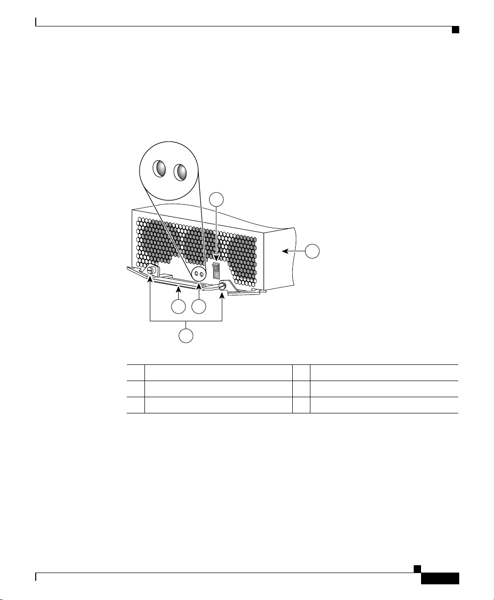
Figure 4-1 shows the location of the LEDs on the power supply faceplate.
Figure 4-1 AC-Input Power Supply LEDs
Problem Solving with Subsystems
3
1
57916
OL-11497-03
2 5
4
1 AC-input power supply 4 Captive screws on release levers
2 Handle 5 LEDs
3 Power standby switch – –
Cisco 12006 and Cisco 12406 Router Installation and Configuration Guide
4-17
Page 18
Problem Solving with Subsystems
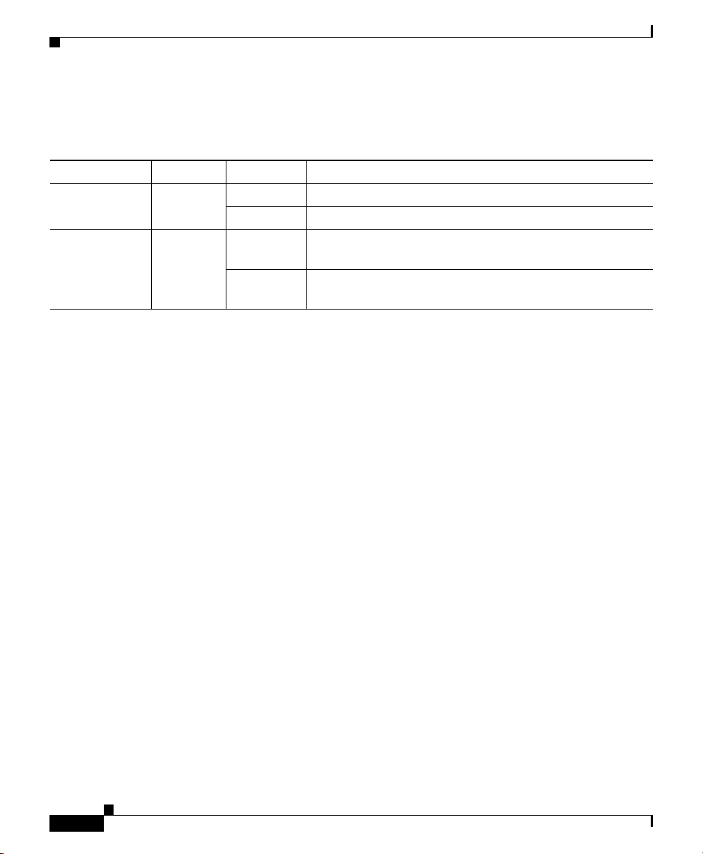
Table 4-6 summarizes the function of these indicators.
Table 4-6 AC-Input Power Supply LED indicators
LED Label Function State Description
AC
(Left LED)
DC
(Right LED)
Input
power
Output
Power
On AC power source is present and is within specified limits.
Off Power source is not within specified limits.
On Power supply is operating normally in a power-on
condition.
Off Power supply is operating in a fault condition and
shutdown has occurred.
Chapter 4 Troubleshooting the Installation
4-18
Cisco 12006 and Cisco 12406 Router Installation and Configuration Guide
OL-11497-03
Page 19

Chapter 4 Troubleshooting the Installation
DC-Input Power Entry Module LEDs
Figure 4-2 shows the location of the LEDs on the DC-input PEM.
Figure 4-2 DC-Input Power Entry Module LEDs
Problem Solving with Subsystems
1 DC-input PEM 4 Captive screws on release levers
2 Handle 5 Air inlet for cooling fan
3 ON/OFF switch – –
Table 4-7 summarizes the function of these indicators.
Table 4-7 DC-Input PEM LED Indicators
LED Label Color Function
OUTPUT OK Green PEM is operating normally in a powered-on condition.
INPUT OK Green DC power is present at the PEM input and within the specified limits.
MISWIRE Amber Indicates input is wired backward at the PDU input.
Cisco 12006 and Cisco 12406 Router Installation and Configuration Guide
OL-11497-03
4-19
Page 20

Problem Solving with Subsystems
Blower Module LEDs
Figure 4-3 shows the location of the LEDs on the blower module.
Figure 4-3 Blower Module Location and Features
1
3
4
Chapter 4 Troubleshooting the Installation
HIGH SPEED BLOW
ER
2 5
1 Blower module 4 Air exhaust vents
2 Blower module LEDs 5 Power distribution unit (PDU)
3 Blower module handle
Cisco 12006 and Cisco 12406 Router Installation and Configuration Guide
4-20
101114
OL-11497-03
Page 21

Chapter 4 Troubleshooting the Installation
When the system is operating correctly, you should see these LED states:
• OK—Green. When on, the green OK LED indicates normal operation.
• FAIL—Off. When on, the red FAIL LED indicates the system has detected a
fan failure or other fault in the blower module.The red LED should remain off
during normal operation.
Alarm Card LEDs
Figure 4-4 shows the location of the LEDs on the faceplate of the alarm card.
Figure 4-4 Alarm Card LEDs
Problem Solving with Subsystems
MBUS
CSC
ENABLED
0
FAI L
01 1 2
SFC
CRITICAL
MAJOR
MINOR
ALARM
66170
1 432 5 6
1 MBus status LED 4 Critical alarm LED
2 CSC status LEDs (two) 5 Major alarm LED
3 SFC status LEDs (three) 6 Minor alarm LED
When the system is operating correctly, the following LED conditions should be
true.
LEDs that normally should be off:
• One MBUS status LED labeled FAIL
• Two CSC status LEDs labeled FAIL
• Three SFC status LEDs labeled FAIL
• Three router alarm LEDs labeled CRITICAL, MAJOR, MINOR
OL-11497-03
Cisco 12006 and Cisco 12406 Router Installation and Configuration Guide
4-21
Page 22

Problem Solving with Subsystems
LEDs that normally should be on:
• One MBUS status LED labeled ENABLED
• Two CSC status LEDs labeled ENABLED
• Three SFC status LEDs labeled ENABLED
RP Alphanumeric LED Displays
Figure 4-5 shows the location of the alphanumeric LEDs on the RP faceplate.
Figure 4-5 RP Alphanumeric LED Displays (Partial Faceplate View)
Chapter 4 Troubleshooting the Installation
Left alphanumeric
LED display (four digits)
Right alphanumeric
LED display (four digits)
57079
When the router is powered on, the four-character alphanumeric displays on the
RP indicate the following:
• Top display—Indicates which RP software component is running.
• Bottom display—Indicates the current phase of the boot process.
Status messages are displayed as the boot process continues. (See Table 4-8 on
page 4-30.)
4-22
Cisco 12006 and Cisco 12406 Router Installation and Configuration Guide
OL-11497-03
Page 23

Chapter 4 Troubleshooting the Installation
Troubleshooting the Power Subsystem
The power subsystem in the Cisco 12006 and Cisco 12406 Routers consists of the
following components:
• An AC PDU or a DC PDU
• One or two AC-DC power supplies, or one or two DC-input PEMs
• Backplane
• DC-DC converters
• MBus modules
The power modules provide DC output to the system via the backplane. DC output
from the alarm card powers the MBus modules on each card in the system. The
MBus modules, in turn, control the DC-DC converters also present on each card
in the system. The DC-DC converter takes DC power from the backplane and
converts it into +2.5, +3.3, and +5 VDC, which is distributed to the card circuitry.
Begin checking the power subsystem by looking at the power module LEDs:
• For DC-input PEMs, see the “Troubleshooting the DC-Input Power Entry
Module” section on page 4-26.
• For AC-input power supplies, see the following section.
Problem Solving with Subsystems
Troubleshooting the AC-Input Power Subsystem
Begin checking the AC-input power subsystem by first looking at the LEDs on the
AC-input power supplies (see the “AC-Input Power Supply LEDs” section on
page 4-17). When you start up the system by turning on facility power to the
system, the following should occur:
• The green LED labeled AC should go on immediately. It should remain on as
long as the system is receiving satisfactory AC power levels from the facility
AC power source.
• The green LED labeled DC indicates the status of the power module DC
output power and internal DC voltages. This LED stays on when all the
following conditions are met:
–
The power supply is fully seated in its bay.
–
The power supply power standby switch is on.
Cisco 12006 and Cisco 12406 Router Installation and Configuration Guide
OL-11497-03
4-23
Page 24

Problem Solving with Subsystems
–
–
–
The power supplies are monitored by the MBus module and the RP for over- or
undervoltage and over- or undercurrent conditions.
To help isolate a problem with an AC-input power supply, follow these steps:
Step 1 If the AC LED is off, verify that the power supply is fully seated in its bay, the
ejector levers are flush with the power supply faceplate, and the captive screws
are secured.
• If the AC LED goes on, go to Step 6.
• If the AC LED remains off, go to Step 2
Chapter 4 Troubleshooting the Installation
For installations in North America, the AC input power range is between
100 and 240 VAC, with a 20A service. For international environments,
the AC input power range is between 185 and 264 VAC, with a 16A
service.
Power supplies are providing –48 VDC to internal components.
All internal DC voltages are within tolerance.
If the AC power source or any of the power supply internal DC voltages
exceed allowable tolerances, the DC LED will not go on, or will go off
shortly after you turn on the power standby switch.
4-24
Step 2 Check the AC power source.
a. Check the AC power cord from the power source to the router.
–
Verify that the power cord is seated securely in the PDU and the AC
outlet.
–
Verify that the power cord is not worn or damaged. If the insulation
appears cracked or broken, or the plugs appear loose, replace the power
cord with a new power cord.
b. Verify that the AC power source circuit breaker is on and has not tripped, and
that the circuit breaker has the proper current rating.
c. Verify that each power supply in the router is attached to a separate AC power
source.
d. If the router is connected to an uninterruptable power supply (UPS), verify
that the UPS is functioning correctly. Note that there might be a UPS for each
power supply in the system.
Cisco 12006 and Cisco 12406 Router Installation and Configuration Guide
OL-11497-03
Page 25

Chapter 4 Troubleshooting the Installation
If the AC power source wiring appears to be okay, but the power supply AC LED
remains off, go to Step 3.
Step 3 Plug the power cord into a different, but compatible AC outlet.
• If the power supply AC LED goes on, the original AC outlet is faulty and
cannot be used. Notify the appropriate facilities personnel and go to Step 6.
• If the power supply AC LED remains off, go to Step 4.
Step 4 Exchange the existing power cord for another power cord.
• If the power supply AC LED goes on, the original power cord is faulty and
must be replaced. The AC portion of the power supply is working normally,
go to Step 6.
• If the AC LED still fails to go on when connected to a different power source
with a new power cord, the power supply is probably faulty. Go to Step 5.
Step 5 If a spare power supply is available, replace the existing module with the spare
and restart the system.
• If the AC LED on the spare power supply goes on, the power supply is
working normally, go to Step 6. The original power supply is faulty and
should be returned for replacement.
Step 6 Is the power supply DC LED on?
• If Yes, the power supply is functioning normally. This is the end of the
procedure.
Problem Solving with Subsystems
OL-11497-03
Note In a Cisco 12006 or Cisco 12406 Router with two power supplies, the output
power from the second power supply is adequate to maintain router operation, so
the following check conditions only apply in a router with one power supply—or
in a case where the second power supply is temporarily disabled by switching it
off.
• If No, and there is no other system activity (blower module is off; line cards
are unpowered), the power supply is faulty and must be replaced. Go to
Step 7.
• If No, but the blower module is operating, suspect a faulty power supply DC
LED. If the blower module is operating, all internal DC voltages are within
tolerance. Use the show environment command to check the voltages on
each card. The blower module uses –48 VDC.
Cisco 12006 and Cisco 12406 Router Installation and Configuration Guide
4-25
Page 26

Problem Solving with Subsystems
Step 7 If a spare power supply is available, replace the existing module with the spare. If
the DC LED then goes on, the power supply is working normally.
Return the faulty power supply for replacement.
If you are unable to resolve the problem or if you determine that either the power
supply or power cable is faulty, contact a service representative for assistance.
Troubleshooting the DC-Input Power Entry Module
Begin checking the DC-input PEM by first looking at the LEDs on the PEM
(see the “DC-Input Power Entry Module LEDs” section on page 4-19).
For a DC-input PEM to operate normally, the following conditions must be true:
• The PEM is fully seated in its bay and the ejector levers are secured.
• DC-input power within the required range is correctly connected to the
chassis PDU terminal connector blocks.
• The circuit breaker on the faceplate of the PEM is switched on.
• The green LEDs labeled OUTPUT OK and INPUT OK on the PEM faceplate
are on, and the yellow LED labeled MISWIRE is off.
Chapter 4 Troubleshooting the Installation
4-26
To help isolate a problem with a DC-input PEM, follow these steps:
Step 1 Is the MISWIRE LED on?
• If Yes, the source DC positive and negative cable leads are connected in
reverse order to the terminal connector block on the PDU.
• If No, go to Step 2.
Step 2 If the INPUT OK LED is off, verify that the PEM is fully seated in its bay, the
ejector levers are flush with the PEM faceplate, and the captive screws are
secured.
• If the INPUT OK LED goes on, go to Step 6.
• If the INPUT OK LED remains off, go to Step 3.
Step 3 Verify that the PEM circuit breaker switch is on.
• If No, switch it on. If the INPUT OK LED goes on, go to Step 6.
Cisco 12006 and Cisco 12406 Router Installation and Configuration Guide
OL-11497-03
Page 27

Chapter 4 Troubleshooting the Installation
• If Yes, go to Step 4.
Step 4 Turn off the PEM circuit breaker switch and check the DC power source:
a. Check the DC power wires from the power source to the router.
• Verify that the power wires are fastened securely at the PDU and the DC
source.
• Verify that the power wires are not worn or damaged. If the insulation appears
cracked or broken, have the power wires replaced.
b. Verify that the DC power source circuit breaker is on, and that the circuit
breaker has the proper current rating.
c. Verify that each PEM in the router is attached to a separate DC power source.
• If the DC power source wiring appears to be okay, and the PEM INPUT OK
LED goes on when you switch on the PEM, go to Step 6.
• If the DC power source wiring appears to be okay, but the power supply
INPUT OK LED remains off when you switch on the PEM, go to Step 5.
Step 5 Remove the PEM and insert it in the second bay in the router, or into a bay on
another Cisco 12006 or Cisco 12406 Router.
• If the INPUT OK LED remains off, the PEM is faulty and must be replaced.
Problem Solving with Subsystems
OL-11497-03
• If the INPUT OK LED goes on, the input portion of the PEM is working
normally, go to Step 6.
Step 6 Is the OUTPUT OK LED on?
• If Yes, the power source is good and the PEM is operating normally. This is
the end of the procedure.
Note In a Cisco 12006 or Cisco 12406 Router with two PEMs, the output power from
the second PEM is adequate to maintain router operation, so the following check
conditions only apply in a router with one PEM—or in a case where the second
PEM is temporarily disabled by switching it off.
• If No, and there is no other system activity (blower module is off; line cards
are unpowered), the PEM is faulty and must be replaced. Go to Step 7.
• If No, but the blower module is operating, suspect a faulty OUTPUT OK
LED. If the blower module is operating, all internal DC voltages are within
tolerance. Use the show environment command to check the voltages on
each card. The blower module uses –48 VDC.
Cisco 12006 and Cisco 12406 Router Installation and Configuration Guide
4-27
Page 28

Problem Solving with Subsystems
Step 7 If a spare PEM is available, replace the existing module with the spare. If the
OUTPUT OK LED then goes on, the PEM is working normally.
Return the faulty PEM for replacement.
If you are unable to resolve the problem or if you determine that either the PEM
or power wiring is faulty, contact a service representative for assistance.
Troubleshooting the Processor Subsystem
The Cisco 12006 and Cisco 12406 Router processor subsystem consists of the RP,
the line cards, and the alarm cards. The RP and the line cards each have two
processors. One processor is the main processor; the other processor is a
component in the MBus module. The MBus module begins operation as soon as
power is applied to the system. The MBus module determines the type of card it
is mounted on and whether it should turn on the DC-DC converter. The RP MBus
module turns on card power after a brief delay; the line card MBus modules delay
turning on power until they receive a command from the RP.
Chapter 4 Troubleshooting the Installation
A Cisco 12006 and Cisco 12406 Router requires that one RP be installed, or the
system cannot operate. A line card that is partially connected to the backplane will
send incomplete signals to the RP, which could cause the system to hang. Line
cards should be completely installed and seated in the backplane connector, or
fully removed and placed in a protective ESD device. If necessary, you can
troubleshoot individual line cards, but first ensure that the RP is installed properly
and the system software has initialized successfully.
A power-on self-test (POST) runs immediately at power-on to determine the
condition of the RP memory. Results are displayed in the alphanumeric LED
display as a pass/fail message.
Troubleshooting the RP
Check the following to help isolate a problem with the RP:
• Both the alphanumeric LED displays are on.
The two displays are powered separately. The left display receives power
from the DC-DC converter on the RP. The right display is powered directly
from the power supply. If the RP is not powered up, its right display may be
Cisco 12006 and Cisco 12406 Router Installation and Configuration Guide
4-28
OL-11497-03
Page 29

Chapter 4 Troubleshooting the Installation
on. If both displays are off, the RP may not be properly seated in the
backplane connector. There also might be a problem with the MBus module
on the RP, or the system power supply might be off.
• If both displays are on, check the message being displayed. As soon as the
DC-DC converter is turned on by the MBus module, the processor on the RP
begins the boot process. Status messages are displayed as the boot process
continues. Tab le 4 -8 provides a list of messages that can be displayed by the
RP alphanumeric LED display. If one of the messages appears frozen, the
boot process could be halted. Make a note of the message being displayed.
Turn off the system power supply power switches, then turn them back on to
reset the system. This starts the boot process again. If the system halts again,
the RP could be faulty and might need to be replaced.
–
If the power modules and blower module appear operational, but none of
the RP LEDs or displays are on, suspect that the RP has not been properly
installed or that the +5 VDC output from the alarm card is faulty.
–
Turn the power switch to each power module to the OFF position.
–
Loosen the two captive screws on the left and right sides of the RP
faceplate, and use the ejector levers to eject and reseat the RP. Tighten the
captive screws, then power up the system by turning the power module
power switches on.
Problem Solving with Subsystems
OL-11497-03
• Is a critical, major, or minor alarm LED on the alarm card on?
–
If any of the three alarm card alarm LED pairs is on, a fault has been
detected in the system. Check the console for messages indicating the
source of the problem.
–
There could be a false error indication originating from the RP. You
might want to reseat or replace the RP.
Caution The RP reset switch resets the RP and the entire system. To prevent system errors
and problems, use it only at the direction of a Cisco-certified service
representative.
Cisco 12006 and Cisco 12406 Router Installation and Configuration Guide
4-29
Page 30

Problem Solving with Subsystems
Table 4-8 RP Alphanumeric LED Display Messages
Chapter 4 Troubleshooting the Installation
LED Display
LMEM
1
Indications
Low-memory test running
2
TEST
LCAH
Lower 15k cache initialization
INIT
BSS
Initialize main memory for ROM
INIT
NVRAM
Initialize NVRAM
INIT
EXPT
Initialize interrupt handlers
INIT
TLB
Initialize TLB
INIT
CACH
Initialize CPU data and instruction cache
INIT
CACH
Enable CPU cache parity
PARY
MEM
Initialize main memory
INIT
NVRAM
Size of the NVRAM
SIZE
PCMC
Initialize the PCMCIA
INIT
EXIT
Exit the initialization sequence
INIT
IOS
The Cisco IOS software is up and running
UP
MSTR
The RP is enabled and recognized by the system
RP
1. The messages shown do not indicate a specific sequence.
2. Some messages appear for a fraction of a second; others last several seconds.
4-30
Cisco 12006 and Cisco 12406 Router Installation and Configuration Guide
OL-11497-03
Page 31

Chapter 4 Troubleshooting the Installation
Troubleshooting the Line Cards
Line cards can be installed in slots in the card cage. As each line card powers up,
a power-on self-test (POST) is performed on the line card memory. A full set of
field diagnostics can also be run on a line card from the system console, providing
a pass/fail message both in the line card alphanumeric LED display and on the
system console.
To help isolate a problem with the line cards, visually check the two alphanumeric
LED displays to determine whether both display banks are on.
The two displays are powered separately. The left display receives power from the
DC-DC converter on the line card. The right display is powered directly from the
backplane. Therefore, even if the line card has not powered up, the right display
could be on. If both displays are off, the line card might not be fully plugged into
the backplane connector, there might be a problem with the MBus module on the
line card, or system power might be off.
If both displays are on, check the message being displayed. As soon as the DC-DC
converter is turned on by the MBus module, the processor on the line card begins
the boot process. Status messages are displayed in the alphanumeric displays as
the boot process continues on the line card.
Problem Solving with Subsystems
OL-11497-03
Table 4-9 provides a list of messages that can be displayed by the line card
alphanumeric LED display. Some of these messages are displayed only for a
fraction of a second; others last for several seconds.
Table 4-9 Line Card Alphanumeric LED Display Messages
LED Display
MEM
1
Indications
POST memory test running
2
TEST
LROM
POST memory test has finished running
RUN
BSS
Initialize main memory for ROM
INIT
RST
Save reset reason register
SAVE
IO
Reset the I/O system on the card
RST
Cisco 12006 and Cisco 12406 Router Installation and Configuration Guide
4-31
Page 32

Problem Solving with Subsystems
Table 4-9 Line Card Alphanumeric LED Display Messages (continued)
Chapter 4 Troubleshooting the Installation
LED Display
EXPT
1
Indications
Initialize interrupt handlers
2
INIT
TLB
Initialize TLB
INIT
CACH
Initialize CPU data and instruction cache
INIT
MEM
Initialize main memory
INIT
LROM
Ready to access download
RDY
ROMI
Getting ROM images
GET
FABL
Wait for load of fabric downloader
WA IT
FABL
The fabric downloader loads
DNLD
FABL
The fabric downloader launches
STRT
FABL
The fabric downloader launch is complete
RUN
IOS
The Cisco IOS software downloads
DNLD
IOS
The Cisco IOS software launches
STRT
IOS
The Cisco IOS software runs in DRAM
UP
IOS
The line card is enabled and ready for use
RUN
1. The messages shown do not indicate a specific sequence.
2. Some messages appear only for a fraction of a second; others last several seconds.
4-32
Cisco 12006 and Cisco 12406 Router Installation and Configuration Guide
OL-11497-03
Page 33

Chapter 4 Troubleshooting the Installation
Troubleshooting by Using the Alarm Cards
The alarm cards are installed in the alarm card slots immediately beneath the
clock and scheduler card slots. The alarm card has four primary functions:
• Redundant generation of the DC MBus supply voltage for the line cards
• Power system monitoring functions
• OK/FAIL status indication of the CSCs and SFCs
• Hardware implementation of the alarm system relay outputs and indicators
The status of these functions is displayed in the LEDs on the faceplate of the alarm
card. (See Figure 4-4.)
Monitoring Alarm Card Status
The alarm card faceplate has one pair of LEDs, labeled MBUS, that indicate the
operational status of the alarm card.
A green MBUS LED labeled ENABLED indicates that the card has been detected
by the system and is okay. A yellow MBUS LED labeled FAIL indicates that the
system has detected a fault in the alarm card.
If no faults have been detected on an alarm card, the green MBUS LED labeled
ENABLED should be on, and the yellow LED labeled FAIL should be off.
Problem Solving with Subsystems
Monitoring Switch Fabric Status
If there are no faults on either CSC 0 or CSC 1, the green LED labeled ENABLED
for each CSC should be on, and the yellow LED labeled FAIL for each CSC
should be off. If the system detects a CSC fault, it turns off the green ENABLED
LED for the faulty card, turns on the yellow FAIL LED, logs a warning message
on the system console, and continues operating.
Note If the yellow LED labeled FAIL for a CSF or SFC is on, check the system console
for messages describing the fault.
Cisco 12006 and Cisco 12406 Router Installation and Configuration Guide
OL-11497-03
4-33
Page 34

Problem Solving with Subsystems
If there are no faults on the SFCs (SFC 0, SFC 1, or SFC 2), the green LED
labeled ENABLED for each SFC should be on, and the yellow LED labeled FAIL
for each SFC should be off. If the system detects an SFC fault, it turns off the
green ENABLED LED for the faulty card, turns on the yellow FAIL LED, logs a
warning message on the system console, and continues operating.
Monitoring Critical, Major, and Minor Alarm Status
The alarm card faceplate is equipped with three pairs of alarm status LEDs that
are used to identify system alarm conditions detected through the MBus:
• Critical
• Major
• Minor
Note The LEDs are paired for redundancy to protect against a single failed LED. If any
of the six LEDs is on, check the system console for messages describing the fault.
Chapter 4 Troubleshooting the Installation
4-34
Because there are two alarm cards in a Cisco 12006 or Cisco 12406 Router, a
system alarm condition detected through the MBus causes the same LEDs to be
illuminated on both alarm cards.
The alarms can warn of an overtemperature condition on a component in one of
the card cages, a fan failure in a blower module, an overcurrent condition in a
power supply, or an out-of-tolerance voltage on one of the cards in one of the card
cages. The LEDs are driven by MBus software, which sets the threshold levels for
triggering the different stages of alarms.
The RP continuously polls the system for temperature, voltage, current, and fan
speed values. If an over-threshold value is detected, the RP sets the appropriate
alarm severity level on the alarm card, which lights one of the LED pairs on the
alarm display and energizes the appropriate alarm display relays, activating any
external audible or visual alarms wired to the alarm display. The RP also logs a
message about the threshold violation on the system console.
Cisco 12006 and Cisco 12406 Router Installation and Configuration Guide
OL-11497-03
Page 35

Chapter 4 Troubleshooting the Installation
Troubleshooting the Cooling Subsystem
Cisco 12006 and Cisco 12406 Routers have a blower module located on the rear
of the chassis, which provides cooling air for the router components.
(See Figure 4-3.)
The blower module receives power and signals though a connector recessed in the
blower module. This connector mates with a connector mounted on the PDU. The
blower module contains three fans, one connector, and one controller card. There
are two LEDs on the blower module faceplate visible at the rear of the chassis.
• Green LED labeled OK—When on, this LED indicates that the blower
module is functioning normally.
• Red LED labeled FAIL—When on, this LED indicates that the blower
module is not functioning normally.
If the green LED is off and/or the red LED is on, check the following to help
isolate a problem with the cooling system:
• Listen for the blower fans. In noisy environments, place your hand behind the
blower module to feel for air being forced out the exhaust vents. If the blower
module fans are on, the DC voltage from the power modules to the blower
module is good.
• If the blower module fans are not on, there could a problem with either the
blower module or the DC power from the power modules.
Problem Solving with Subsystems
OL-11497-03
–
Check the output power LED on each power module (DC LED on the
AC-input power supply; OUTPUT OK LED on a DC-input PEM). If the
output power LED on a power module is off, but the input power LED is
on, the power module might be faulty and should be checked or replaced.
–
If the output power LED on the power module is on (DC output is OK),
but the blower module remains off, verify that the blower module is
seated properly in the chassis.
Remove the blower module by loosening the four captive screws holding
it to the chassis, pull the blower module away from the chassis, then
firmly push the blower module against the chassis to reseat the blower
module. Tighten the four captive screws.
• If the blower module remains off, there could be a problem with the blower
module controller card.
Cisco 12006 and Cisco 12406 Router Installation and Configuration Guide
4-35
Page 36

Problem Solving with Subsystems
• The following console monitor message indicates that the system has
detected an overtemperature or out-of-tolerance power condition in the
router:
Queued messages:
%ENVM-1-SHUTDOWN: Environmental Monitor
initiated shutdown
If an environmental shutdown results from an out-of-tolerance power
condition, the output fail LED on the power module will go on before the
system shuts down. Refer to the “Troubleshooting the Power Subsystem”
section on page 4-23.”
• Although overheating is unlikely at initial startup, be sure that heated exhaust
air from other equipment is not entering the air filter, and that there is
sufficient clearance—at least 6 inches (15.24 cm)— around the front and rear
of the chassis to allow cooling air to enter and hot air to exhaust.
• Check the condition of the two air filters located in slots on the right side of
the chassis. If the air filters appear dirty, remove the filters and either vacuum
them or replace them.
• The preceding message could also indicate a faulty component or temperature
sensor. Before the system shuts down, use the show environment all or show
environment table command to display the internal system environment,
including voltages and temperatures measured at each card.
If the blower module is faulty, you must replace the entire blower module.
Chapter 4 Troubleshooting the Installation
4-36
If you are still unable to resolve the problem, contact a service representative for
assistance.
Cisco 12006 and Cisco 12406 Router Installation and Configuration Guide
OL-11497-03
 Loading...