

Page 1

Overview
APPENDIX
A
Technical Specifications
Appendix A provides the technical specifications for the Cisco 12404 Internet
router, and procedures for repackaging the router.
• Product Architecture, page A-2
• Fan Tray Assembly, page A-25
• Air Filter, page A-27
• Chassis Cable-Management System, page A-28
• Maintenance Bus, page A-28
This appendix includes the following environmental specifications.
• Temperature, humidity, and altitude ranges
• Operating and storing the product
• Memory requirements
OL-11636-01
• Physical characteristics
• Dimensions and weight
• Power supply characteristics
• Output capacity
• Power dissipation
• Heat dissipation
Cisco 12404 Internet Router Installation and Configuration Guide
A-1
Page 2

Product Architecture
• Voltage frequency
• Listing agency approvals
Product Architecture
Table A-1 lists system level requirements for the Cisco 12404 Internet router.
Table A-1 Cisco 12404 Internet Router Product Architecture
Feature Description
Slot Capacity 4 slots
Chassis One card cage with five slots, three OC192 pitch slots, one RP
Height Not to exceed 8.75 inches; supports 8 systems per 7 ft. rack
Width 19 inch rack mountable
Depth 27.85 in. (70.74 cm) maximum
Switching
Capacity
Cooling Side-to-side cooling
Power Supplies 110V AC
Appendix A Technical Specifications
3 OC192 capable I/O slots
1 RP slot that is 10G capable
1 CSF/alarm card
slot and one CSF slot
10 Gbps full-duplex switching capacity per slot.
This includes the RP slots. Each slot capable of supporting all
current and future Engine 0, Engine 1, Engine 2, Engine 3 and
Engine 4 based line cards.
Specific interfaces include OC192c, QOC48c, 10GE,
10x1GE, etc, 3xGE, 1xGE, 8xFE and other 10GiG cards.
The switching capacity is required to handle all four 10GiG
capable slots (including RP), thus the total switching capacity
will be 80 Gbps full-duplex
220V AC
DC (optional)
A-2
Cisco 12404 Internet Router Installation and Configuration Guide
OL-11636-01
Page 3

Appendix A Technical Specifications
Table A-1 Cisco 12404 Internet Router Product Architecture (continued)
Feature Description
Power
Requirements
Power Supply
Redundancy
Route
Processors
Route
Processor
Redundancy
Switch Fabric The switch fabric supports up to 80 Gbps of capacity
NEBS The Cisco 12404 Inernet Router is designed to comply with
1. A narrow card filler panel must be used to ensure proper air flow through the chassis and
electromagnetic compatibility (EMC)
Product Architecture
110V AC power, sufficient to handle three OC192c /10GE
capable line cards and one 10G capable RP.
Total power supplied to the system should not exceed
1200VA
Two AC or DC power supplies in redundant configuration
should be able to support the entire power needs of the
chassis.
Redundant and load sharing AC power entry module (PEMs),
or
Redundant and load sharing DC PEMs and DC power
distribution units (PDUs)
Supports up to 2 RPs per system
The second RP can be used in any slot
The first RP is inserted in slot 0 (1.25 inch height) see
Figure A-4
Supports online insertion and removal, hot swappable RP
redundancy
NEBS Level 3 certification
1
Specifications
OL-11636-01
Table A-2 lists Cisco 12404 Internet router physical specifications. Table A -3
lists the environmental specifications.
Cisco 12404 Internet Router Installation and Configuration Guide
A-3
Page 4

Product Architecture
Appendix A Technical Specifications
Table A-2 Cisco 12404 Internet Router Physical Specifications
Description Value
Frame height 8.75 inches (22.2 cm)
Frame width 19 inches (48.3 cm)
Frame depth 26 inches (66.0 cm)
Weight
Maximum configuration
Minimum configuration
Table A-3 Cisco 12404 Internet Router Environmental Requirements
Environmental
Requirements Ranges
Temperature 32 to 104F (0 to 40 C) operating
Humidity 10 to 90% non-condensing operating
Altitude 0 to 10,000 ft. (0 to 3,050 m) operating
Heat dissipation 3,343 Btu/hr. maximum
Cooling Facing the router, right side-to-side cooling
Shock 5 to 500 Hz, 0.5g (0.1 oct/min
1. oct/min = Octave per minute
103 pounds (46.7 kg)
73 pounds (33.1 kg) (without line cards)
-4 to 149F (-20 to 65 C) non-operating
-5 to 133F (-23 to 55 C) Max operating for 96 hrs.
only
5 to 95% non-condensing non-operating
0 to 30,000 ft. (0 to 9,144 m) non-operating
1
) operating
5 to 100Hz, 1g (0.1 oct/min) non-operating
100 to 500Hz, 15g (0.2 oct/min)
500 to 1,000Hz, 1.5g (0.2 oct/min)
A-4
Cisco 12404 Internet Router Installation and Configuration Guide
OL-11636-01
Page 5

Appendix A Technical Specifications
Product Architecture
Warning
Exhaust from other equipment vented directly into the Cisco 12404 Internet
router air inlet may cause an over-heat condition. Install the router so that it is
protected from a direct flow of hot air from other equipment.
AC-Powered Routers
At sites where the Cisco 12404 router operates with AC PEMs, observe the
following guidelines.
• A power factor corrector (PFC) allows the PEM to accept AC power source
voltage from an AC power source operating between 100–120 VAC, 15–Amp
service in North America; and a range of 185–264 VAC, 10–Amp service, in
an international environment.
• All AC PEM power cords measure 14 feet (4.3 meters).
• Provide a dedicated power source for each PEM installed in the router.
• Install an uninterruptable power source where possible.
AC Power Plugs
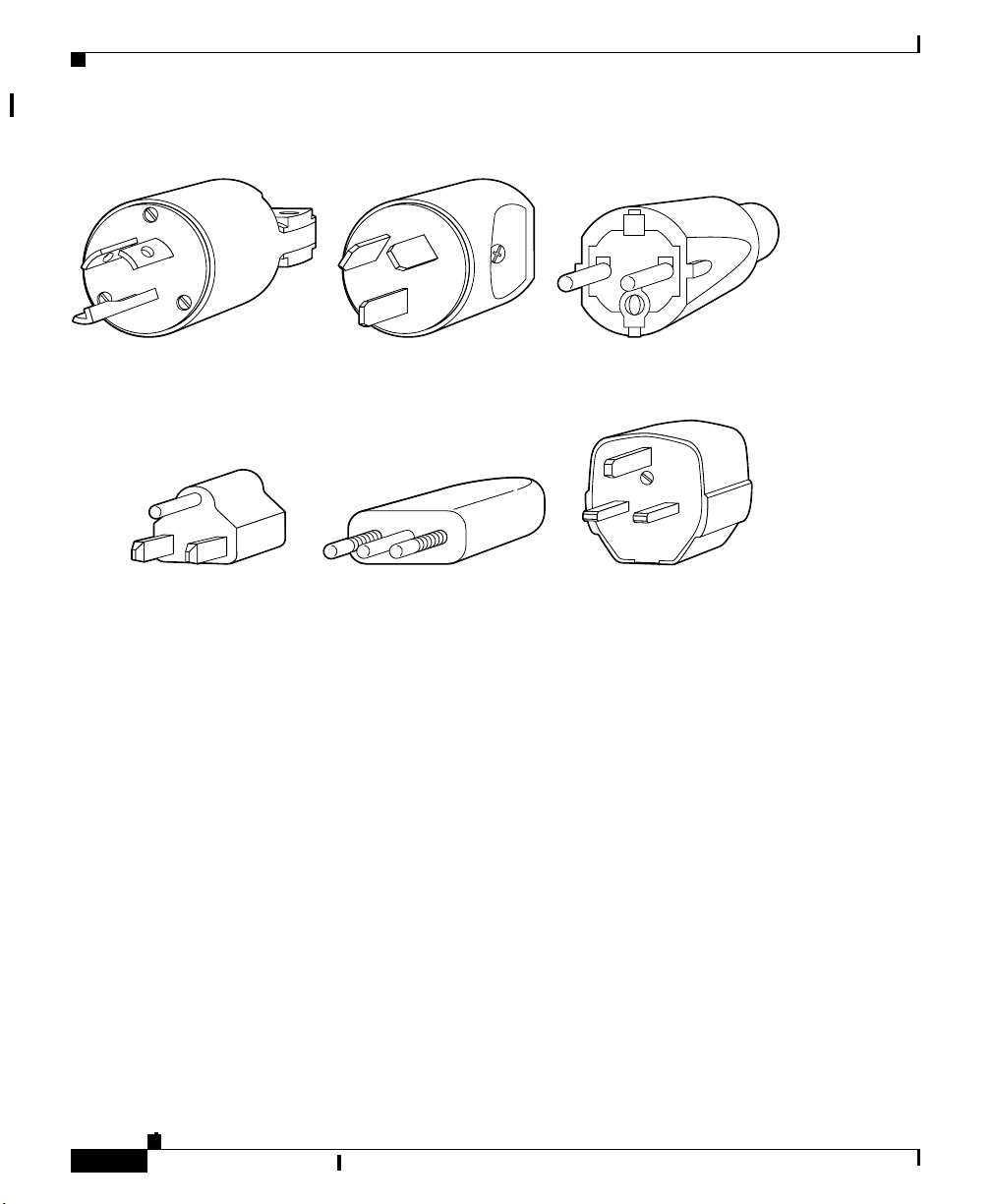
Different styles of AC input power cords are shown in Figure A-1.
OL-11636-01
Cisco 12404 Internet Router Installation and Configuration Guide
A-5
Page 6
Product Architecture
Figure A-1 AC Power Plugs
Appendix A Technical Specifications
North American plug
L6-20 20A
(for 240V units)
North American plug
5-15 15A
Route Processor
Each Cisco 12404 Internet router has one main system (or route) processor. The
route processor (RP) processes the network routing protocols and distributes
updates to the Cisco Express Forwarding (CEF) tables on the line cards. The RP
also performs general maintenance functions, such as diagnostics, console
support, and line card monitoring.
Two types of RPs are available for the Cisco 12404 Internet router:
• Gigabit Route Processor (GRP)
• Performance Route Processor (PRP)
Australian plug
AS 3112 10A
Italian plug
CEI 23-16/VII 10A
European plug
CEE 7/7 16A
United Kingdom plug
BS 1363 13A
66969
A-6
Cisco 12404 Internet Router Installation and Configuration Guide
OL-11636-01
Page 7
Appendix A Technical Specifications
Gigabit Route Processor
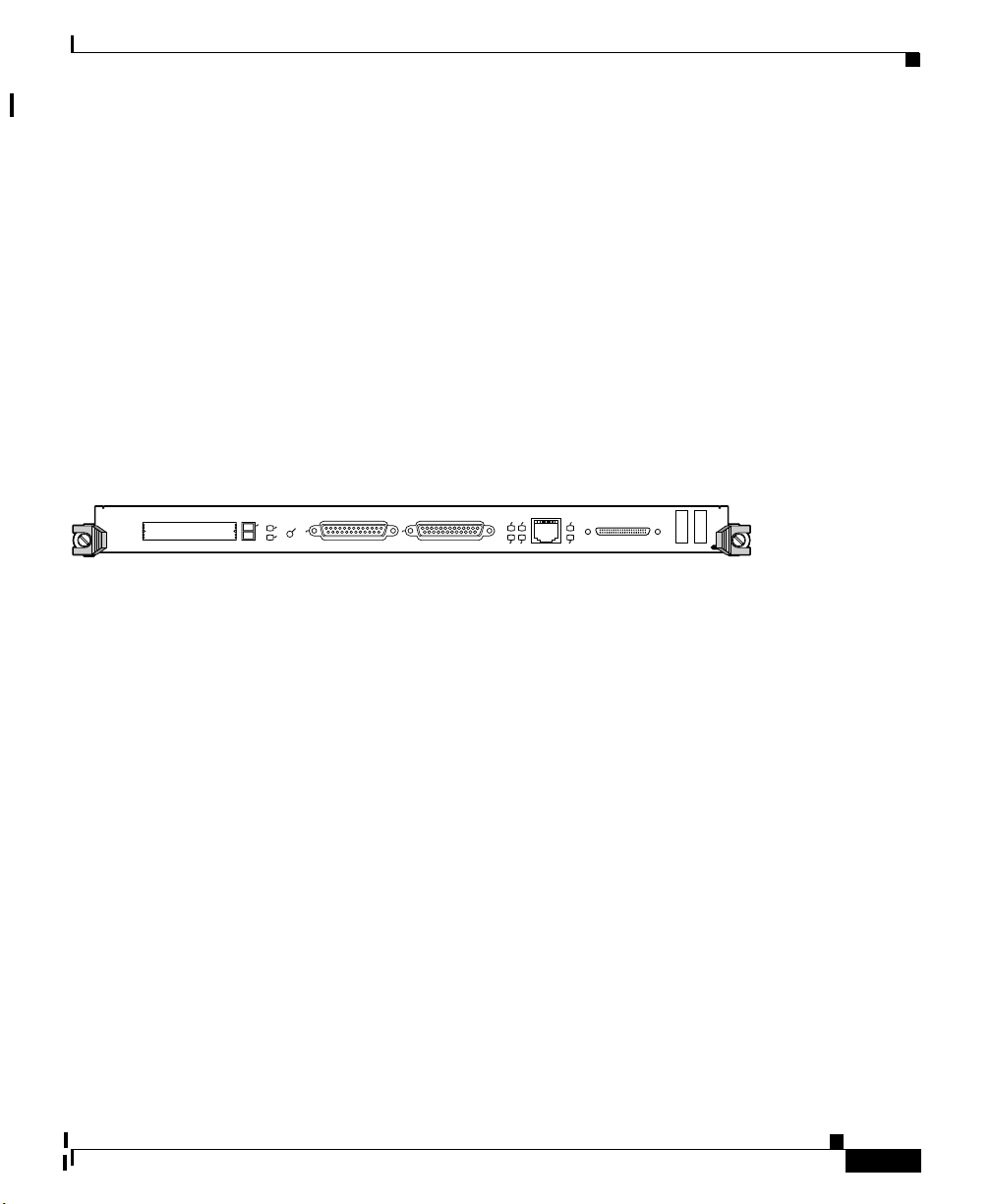
This section provides an overview of the GRP (Figure A-2) and its use as the main
system processor for the Cisco 12404 Internet router.
This section provides information on the following GRP functionality.
• GRP memory
• System status LEDs
• Soft reset switch
• PCMCIA slots
• Asynchronous serial ports
Figure A-2 Gigabit Route Processor
EJECT
SLOT-1
RESET
SLOT-0
AUX
The following are primary functions of the GRP.
• Loading the Cisco IOS software to all of the installed line cards at power on
• Providing a console (terminal) port for router configuration
CONSOLE
Product Architecture
COLL
RX
RJ-45
TX
MII
LINK
GIGABIT ROUTE PROCESSOR
57074
OL-11636-01
• Providing an auxiliary port for other external equipment (such as modems)
• Providing an IEEE 802.3, 10/100-megabit-per-second (Mbps) Ethernet port
for Telnet functionality
• Running routing protocols
• Building and distributing routing tables to the line cards
• Providing general system maintenance functions for the router
The GRP communicates with the line cards either through the CSF or through the
maintenance bus (MBus). The CSF connection is the main data path for routing
table distribution as well as for packets that are sent between the line cards and
the GRP.
Cisco 12404 Internet Router Installation and Configuration Guide
A-7
Page 8

Appendix A Technical Specifications
Product Architecture
The MBus connection allows the GRP to download a system bootstrap image,
collect or load diagnostic information, and perform general, internal system
maintenance operations. The GRP plugs into any slot in the card cage in the
Cisco 12404 Internet router. The router is shipped with 20MB of Flash memory
as the default configuration.
GRP Memory
Memory components of the GRP are listed in Tab l e A -4.
Table A-4 GRP Memory Components
Type Size Quantity Description
DRAM 64
DIMM 3.3-volt, 60 nanosecond device
SRAM 512 KB
NVRAM 512 KB
Flash Memory
(SIMM)
4
Flash Memory
(card)
Flash boot
ROM
1. 64 MB of DRAM is the default DRAM configuration for the GRP.
2. SRAM is not able to be upgraded or configured.
3. NVRAM is not able to be upgraded or configured.
4. SIMM socket is wired for a Cisco design and does not accept industry-standard 80-pin Flash SIMMs.
5. 20-MB Flash memory card is the default shipping configuration for the Cisco 12404 Internet router.
1
to 256 MB
1 or 2 64- or 128-MB DIMMs (based on DRAM required) for
main Cisco IOS software functions.
SRAM for secondary CPU cache memory functions.
Nonvolatile random-access memory (NVRAM) for the
system configuration file.
(fixed)
(fixed)
2
3
8 MB 1 Contains Cisco IOS software images and other
user-defined files on the GRP.
5
20 MB
Up to 2 Contains Cisco IOS software images and other
user-defined files on up to two PCMCIA-based Flash
memory cards.
512 KB 1 Flash EPROM for the ROM monitor program boot
image.
A-8
Cisco 12404 Internet Router Installation and Configuration Guide
OL-11636-01
Page 9
Appendix A Technical Specifications
The Cisco IOS software images that run the Cisco 12404 router reside in Flash
memory, which is located on the GRP in the form of a single in-line memory
module (SIMM), and on up to two (PCMCIA) cards (called Flash memory cards)
that insert in the two PCMCIA slots on the front of the GRP. Storing the Cisco
IOS images in Flash memory enables you to download and boot from upgraded
Cisco IOS images remotely or from software images resident in GRP Flash
memory.
The Cisco 12404 router supports system software downloads for most Cisco IOS
software upgrades, which enables you to remotely download, store, and boot from
a new Cisco IOS image. See Figure A-2.
DRAM
The EDO DRAM on the GRP stores routing tables, protocols, and network
accounting applications; it also runs the Cisco IOS software. The default GRP
DRAM configuration is 64 megabytes of EDO DRAM, which you can increase up
to 256 MB through DRAM upgrades. The Cisco IOS software runs from within
GRP DRAM. Table A-5 lists the DRAM configurations and upgrades.
Product Architecture
OL-11636-01
Caution To prevent memory problems, DRAM DIMMs must be 3.3-volt, 60-nanosecond
devices. Do not attempt to install other devices in the DIMM sockets.
Table A-5 DRAM Configurations
Total DRAM Product Numbers DRAM Sockets Number of DIMMs
1
64 MB
MEM-GRP/LC-64(=) U39 (bank 1) One (1) 64-MB
DIMM
128 MB MEM-GRP/LC-64(=) U39 (bank 1) and
U42 (bank 2)
Two (2) 64-MB
DIMMs
128 MB MEM-GRP/LC-128(=) U39 (bank 1) One (1) 128-MB
DIMM
256 MB MEM-GRP/LC-256(=) U39 (bank 1) and
U42 (bank 2)
1. 64 MB of DRAM is the default DRAM configuration for the GRP.
Cisco 12404 Internet Router Installation and Configuration Guide
Two (2) 128-MB
DIMMs
A-9
Page 10

Product Architecture
SRAM
NVRAM
Appendix A Technical Specifications
The SRAM provides secondary CPU cache memory. The standard GRP
configuration is 512 KB. The principle function of SRAM is to act as a staging
area for routing table update information to and from the line cards. SRAM is not
able to be upgraded or configured.
The system configuration, software configuration register settings, and
environmental monitoring logs are contained in the 512-KB NVRAM, which is
backed up with built-in lithium batteries that retain the contents for a minimum of
5years. NVRAM is not able to be upgraded or configured
Caution Before you replace the GRP in the system, back up the running configuration to a
Trivial File Transfer Protocol (TFTP) file server or an installed Flash memory
card so you can retrieve it later.
If the configuration is not saved, the entire configuration is lost inside the
NVRAM on the removed GRP and you must re-enter the entire configuration
manually.
This procedure is not necessary if you are temporarily removing a GRP; lithium
batteries retain the configuration in memory until you replace the GRP in the
router.
Flash Memory
PCMCIA Slots
A-10
Both the onboard and PCMCIA card-based Flash memory allow you to remotely
load and store multiple Cisco IOS software and microcode images. You can
download a new image over the network or from a local server and then add the
new image to Flash memory or replace the existing files. You can then boot the
routers either manually or automatically from any of the stored images. Flash
memory also functions as a TFTP server to allow other servers to boot remotely
from stored images or to copy them into their own Flash memory.
The GRP has two PCMCIA slots. Either slot can support a Flash memory card or
an input/output (I/O) device as long as the device requires only +5 VDC.
Cisco 12404 Internet Router Installation and Configuration Guide
OL-11636-01
Page 11

Appendix A Technical Specifications
Product Architecture
LED Types
Table A-6 describes the types of system status light emitting diodes (LED) used
on the GRP.
Table A-6 System Status LED Types, Description, and Power Source
LEDs Description and Power Source
2 PCMCIA Activity LEDs (one per PCMCIA slot) light when the slot is accessed. The
LEDs receive power from the switched slot voltage.
4 RJ-45 Ethernet port LEDs are used in conjunction with the RJ-45 Ethernet
connector. The LEDs indicate link activity, collision detection, data
transmission, and data reception.
When the MII Ethernet port is in use, the LEDs are disabled.
2 RJ-45 or MII Ethernet port select LEDs when on, identify which one of the two Ethernet
connections you selected. When the RJ-45 port is selected, its LED is on
and the MII LED is off. When the MII port is selected, its LED is on and
the RJ-45 LED is off.
Alphanumeric displays These alphanumeric LED displays are controlled directly by the MBus and
provide information about the system status during the boot process.
Alphanumeric displays are organized as two rows of four characters each.
The displays’ content is controlled by the MBus module software. Both
rows of the display are powered by the MBus module.
After the boot process, the LEDs are controlled by Cisco IOS software
through the MBus, and display messages designated by Cisco IOS
software.
Asynchronous Serial Ports
Two asynchronous serial ports on the GRP, the console and auxiliary ports, allow
you to connect external devices to monitor and manage the system.
The consoleport is an Electronics Industries Association/Telecommunications
Industry Association (EIA/TIA)-232 receptacle (RS-232 female) that provides a
data circuit-terminating equipment (DCE) interface for connecting a console
terminal.
OL-11636-01
Cisco 12404 Internet Router Installation and Configuration Guide
A-11
Page 12

Product Architecture
Note EIA/TIA-232 was known as recommended standard RS-232 before its acceptance
Ethernet Port
Appendix A Technical Specifications
as a standard by the EIA/TIA.
The auxiliary port is an EIA/TIA-232 plug (male) that provides a data terminal
equipment interface. The auxiliary port supports flow control and can be used to
connect a modem, a channel service unit (CSU), or other optional equipment for
Telnet management.
The GRP has one Ethernet port available, using one of the following two
connection types:
• RJ-45 receptacle—An 8-pin media dependent interface (MDI) RJ-45
receptacle for either IEEE 802.3 10BASE T (10 Mbps) or IEEE 802.3u
100BASE TX (100 Mbps) Ethernet connections.
• MII receptacle—A 40-pin media independent interface (MII) receptacle that
provides additional flexibility in Ethernet connections. The pinout of this
standard 40-pin receptacle is defined by the IEEE 802.3u standard.
Note The RJ-45 and MII receptacles on the GRP represent two physical
connection options for one Ethernet interface; therefore, you can use
either the MDI RJ-45 connection or the MII connection, but not both at
the same time.
Performance Route Processor
This section provides an overview of the PRP (Figure A-3) and its use as the main
system processor for the Cisco 12404 router.
This section provides information on the following PRP functionality.
• PRP memory
• System status LEDs
• Soft reset switch
• PCMCIA slots
Cisco 12404 Internet Router Installation and Configuration Guide
A-12
OL-11636-01
Page 13

Appendix A Technical Specifications
• Asynchronous serial ports
Figure A-3 Performance Route Processor
Product Architecture
EJECT
ETH 1ETH 0 AUX
SLOT-1
SLOT-0
PRIMARY
RX
TX
PRIMARY
EN
LINK
EN
LINK
CONSOLE
RX
TX
RESET
PERFORMANCE ROUTE PROCESSOR 1 (PRP-1)
The following are primary functions of the PRP.
• Loading the Cisco IOS software to all of the installed line cards at power on
• Providing a console (terminal) port for router configuration
• Providing an auxiliary port for other external equipment (such as modems)
• Providing an IEEE 802.3, 10/100-megabit-per-second (Mbps) Ethernet port
for Telnet functionality
• Running routing protocols
• Building and distributing routing tables to the line cards
• Providing general system maintenance functions for the Cisco 12404 router.
The PRP communicates with the line cards either through the CSF or through the
maintenance bus (MBus). The CSF connection is the main data path for routing
table distribution as well as for packets that are sent between the line cards and
the PRP.
The MBus connection allows the PRP to download a system bootstrap image,
collect or load diagnostic information, and perform general, internal system
maintenance operations. The PRP plugs into any slot in the card cage in the
Cisco 12404 router. The router is shipped with 20MB of Flash memory as the
default configuration.
75041
PRP Memory
OL-11636-01
Memory components of the PRP are listed in Table A-7.
Cisco 12404 Internet Router Installation and Configuration Guide
A-13
Page 14

Appendix A Technical Specifications
Product Architecture
Table A-7 PRP Memory Components
Type Size Quantity Description
SDRAM
SRAM
NVRAM
Flash Memory 64 MB SIMM
Flash Memory
(card)
Flash boot
ROM
1. Default SDROM configuration is 512 MB. Bank 1 (U15) must be populated first. You can use one or both banks to configure
2. SRAM is not user configurable or field replaceable.
3. NVRAM is not user configurable or field replaceable.
4. Flash memory SIMM is not user configurable or field replaceable.
5. ATA Flash disks, and Type I and Type II linear Flash memory cards are supported.
1
2
3
512MB, 1GB,
or 2 GB
1 or 2 512-MB or 1-GB DIMMs (based on SDRAM required)
for main Cisco IOS software functions.
2 MB (fixed) Secondary CPU cache memory functions.
2 MB (fixed) 1 Nonvolatile random-access memory (NVRAM) for the
system configuration file.
4
1 Contains Cisco IOS software images and other
user-defined files on the PRP.
5
20 MB
Up to 2 Contains Cisco IOS software images and other
user-defined files on up to two PCMCIA-based Flash
memory cards.
512 KB 1 Flash EPROM for the ROM monitor program boot
image.
SDRAM combinations of 512 MB, 1 GB, or 2 GV. 1.5-GB configurations are not supported.
A-14
The Cisco IOS software images that run the Cisco 12404 router reside in Flash
memory, which is located on the PRP in the form of a single in-line memory
module (SIMM), and on up to two (PCMCIA) cards (called Flash memory cards)
that insert in the two PCMCIA slots on the front of the PRP. Storing the Cisco IOS
images in Flash memory enables you to download and boot from upgraded Cisco
IOS images remotely or from software images resident in PRP Flash memory.
The Cisco 12404 router supports system software downloads for most Cisco IOS
software upgrades, which enables you to remotely download, store, and boot from
a new Cisco IOS image. See Figure A-3.
Cisco 12404 Internet Router Installation and Configuration Guide
OL-11636-01
Page 15

Appendix A Technical Specifications
SDRAM
SDRAM—The SDRAM on the PRP stores routing tables, protocols, and network
accounting applications; it also runs the Cisco IOS software. The default PRP
configuration includes 512 MB of error checking and correction (ECC) SDRAM.
DIMM upgrades of 512 MB and 1 GB are available. You cannot mix memory
sizes. If two DIMMS are installed, they must be the same memory size. Supported
memory configurations are listed in Tabl e A - 8 .
Caution Cisco strongly recommends that you use only Cisco-approved memory. To
prevent memory problems, SDRAM DIMMs must be +3.3VDC,
PC133-compliant devices. Do not attempt to install other devices in the DIMM
sockets.
Product Architecture
.
SRAM
Table A-8 Supported PRP Route Memory Configurations
Total Route Memory Cisco Product Number DIMM Modules
512 MB
1 GB MEM-PRP-512=
1
— 1 512-MB DIMM
2
2 512-MB DIMMs
1 GB MEM-PRP-1G= 1 1-GB DIMM
1.5 GB
3
——
2 GB NA 2 1-GB DIMMs
1. One 512-MB DIMM is the default shipping configuration.
2. Upgrades PRP to 1 GB by adding a second 512-MB DIMM.
3. This memory size is not supported.
The SRAM provides secondary CPU cache memory. The standard PRP
configuration is 2 MB. The principle function of SRAM is to act as a staging area
for routing table update information to and from the line cards. SRAM is not able
to be upgraded or configured.
OL-11636-01
Cisco 12404 Internet Router Installation and Configuration Guide
A-15
Page 16

Product Architecture
NVRAM
Caution Before you replace the PRP in the system, back up the running configuration to a
Flash Memory
Appendix A Technical Specifications
The system configuration, software configuration register settings, and
environmental monitoring logs are contained in the 2 MB NVRAM, which is
backed up with built-in lithium batteries that retain the contents for a minimum of
five years. NVRAM is not able to be upgraded or configured
Trivial File Transfer Protocol (TFTP) file server or an installed Flash memory
card so you can retrieve it later.
If the configuration is not saved, the entire configuration will be lost inside the
NVRAM on the removed PRP and you will have to reenter the entire
configuration manually.
This procedure is not necessary if you are temporarily removing a PRP; lithium
batteries retain the configuration in memory until you replace the PRP in the
router.
A-16
Both the onboard and PCMCIA card-based Flash memory allow you to remotely
load and store multiple Cisco IOS software and microcode images. You can
download a new image over the network or from a local server and then add the
new image to Flash memory or replace the existing files. You can then boot the
routers either manually or automatically from any of the stored images. Flash
memory also functions as a TFTP server to allow other servers to boot remotely
from stored images or to copy them into their own Flash memory.
Cisco 12404 Internet Router Installation and Configuration Guide
OL-11636-01
Page 17

Appendix A Technical Specifications
Table A-9 lists the supported Flash disk sizes and their Cisco product numbers.
Table A-9 Supported Flash Disk Sizes and Product Numbers
Product Architecture
PCMCIA Slots
Flash Disk Size
2
64 MB
1
Product Number
MEM-12KRP-FD64=
128 MB MEM-12KRP-FD128=
1 GB MEM-12KRP-FD1G=
1. Standard Type 1 and Type 2 linear Flash memory cards also are
supported, although they may not have the capacity to meet the
requirements of your configuration.
2. 64-MB ATA Flash disk is the default shipping configuration.
The PRP has two PCMCIA slots. Either slot can support a Flash memory card or
an input/output (I/O) device as long as the device requires only +5 VDC.System
Status LEDs
OL-11636-01
Cisco 12404 Internet Router Installation and Configuration Guide
A-17
Page 18

Appendix A Technical Specifications
Product Architecture
LED Types
Table A-10 lists system status light emitting diodes (LED) used on the PRP.
Table A-10 System Status LED Types, Description, and Power Source
LEDs Description and Power Source
2 PCMCIA Activity LEDs (one per PCMCIA slot) light when the slot is accessed. The
LEDs receive power from the switched slot voltage.
4 RJ-45 Ethernet port LEDs are used in conjunction with the RJ-45 Ethernet
connector. The LEDs indicate link activity, port enabled, data transmission,
and data reception.
2 Ethernet connection The Ethernet connection LEDs (labeled Primary), when on, identify which
of the two Ethernet connections is selected. Because both ports are
supported on the PRP, the LED on port ETH0 is always on. The ETH1 LED
goes on when it is selected.
Alphanumeric displays The alphanumeric LED displays are controlled directly by the MBus and
provide information about the system status during the boot process.
Alphanumeric displays are organized as two rows of four characters each.
The displays’ content is controlled by the MBus module software. Both
rows of the display are powered by the MBus module.
After the boot process, the LEDs are controlled by the Cisco IOS software
through the MBus, and display messages designated by the Cisco IOS
software.
Asynchronous Serial Ports
The PRP has two asynchronous serial ports, the console and auxiliary ports. These
allow you to connect external serial devices to monitor and manage the system.
Both ports use RJ-45 receptacles.
The console port provides a data circuit-terminating equipment (DCE) interface
for connecting a console terminal. The auxiliary port provides a data terminal
equipment (DTE) interface and supports flow control. It is often used to connect
a modem, a channel service unit (CSU), or other optional equipment for Telnet
management.
Cisco 12404 Internet Router Installation and Configuration Guide
A-18
OL-11636-01
Page 19

Appendix A Technical Specifications
Ethernet Port
The PRP includes two Ethernet ports, both using an 8-pin RJ-45 receptacle for
either IEEE 802.3 10BASE-T (10 Mbps) or IEEE 802.3u 100BASE-TX
(100 Mbps) connections.
Note The transmission speed of the Ethernet ports is auto-sensing by default and is user
configurable.
Line Cards
The Cisco 12404 router is shipped with up to 3 installed line cards that provide a
variety of network media types (based on the order). The line cards can be
installed in slots 0 through 3 in the line card cage and interface to each other and
to the RP through the CSF (Figure A-4). Horizontal cable-management brackets
attach to each line card to manage and organize the network interface cables.
Product Architecture
OL-11636-01
Note Slot 0 (zero) is one slot above the slot labeled Fabric Alarm.
Figure A-4 RP and Line Card Slot Numbers and CSF Location
3
2
1
0
Fabric Alarm
Cisco 12404 Internet Router Installation and Configuration Guide
66252
A-19
Page 20

Product Architecture
Line cards installed in the Cisco 12404 router support online insertion and
removal, which means you can remove and replace (hot-swappable) a line card
while the router remains powered on.
Caution To ensure adequate airflow through the card cage, empty card slots must have a
card blank installed.
Consolidated Switch Fabric Status
An OK/Fail pair of LEDs are provided to indicate the status of the Alarm MBus
and Fabric MBus. The green light indicates that the MBus module is operating
properly. The Fail light indicates that the MBus has detected some error, in itself,
or with the MBus power supply.
Power Entry Module Monitoring
The CSF and alarm card provides monitoring of the PEM. Table A- 11 provides
alarm definitions.
Appendix A Technical Specifications
Table A-11 CSF and Alarm Monitoring Status Definitions
Status Definition
Power Fail Power is not being provided to the power supply
Power Fault A fault exists in the power supply
Missing Module One of the PEMs is not present
Voltage Monitor A voltage monitor signal in the range of 0 to 4.096 V
Current Monitor A current monitor signal in the range of 0 to 4.096 V
P8 Alarm Relay Contact Connector
This connector is a standard DB-9 connector. The relay interface is rated at max
2A, 60V or 50VA, whichever is greater.
Cisco 12404 Internet Router Installation and Configuration Guide
A-20
is provided to the MBus controller to measure the
power supply output voltage level
is provided to the MBus controller to measure the
power supply output current level.
OL-11636-01
Page 21

Appendix A Technical Specifications
MBus Module Port Pin Assignments
Twenty general purpose pins and four analog input pins on the MBus module are
used for this design.
CSF Functionality
The CSF circuity provides synchronized speed interconnections for the line cards
and the RP (Figure A-5). The CSF circuitry consists of clock and scheduler, and
switch fabric functionality; is contained on one card, housed in the bottom slot in
the chassis. The CSF card has a switching capacity of 40 Gbps.
Figure A-5 CSF Card Slot
Product Architecture
C
L
A
S
C
S
L
1
E
L
A
A
N
S
E
R
P
R
C
O
O
N
D
N
L
E
U
A
C
C
S
T
O
E
T
W
R
R
I
TH
P
AL
R
O
C
O
D
H
U
OL
K
T
W
D
I
PE
E
S
R
B
K
EF
L
O
A
P
RE
S
R
S
O
E
CO
D
1
U
NN
I
E
T
CT
L
IN
A
G
S
E
R
D
E
C
L
A
S
S
E
1
P
R
O
D
U
C
T
O
L
A
S
E
R
D
E
C
LA
0
S
S
E
1
1
T
C
E
1
J
-
E
T
O
T
L
E
S
S
0
E
T
R
O
L
S
AUX
O
C
C
R
IT
M
IC
A
M
J
A
IN
O
L
O
R
R
Clock and Scheduler Functionality
The CSF card generates and distributes system-wide clock and cell time
synchronization signaling. System clock generation is delivered to the system via
the backplane and local clock functions are derived from the system clock.
System Clock
The system clock synchronizes data transfers between line cards or between the
RP and a line card through the CSF. The system clock signal is sent to all line
cards and the RP.
Cisco 12404 Internet Router Installation and Configuration Guide
OL-11636-01
23
E
L
O
S
N
FAIL
ENABLE
C
O
N
S
O
L
I
D
T
X
R
X
A
C
T
I
V
E
C
A
R
R
I
E
R
R
X
P
K
T
4
0C
48
L
/P
L
O
S
O
-SR
X
C
K
IN
L
MBUS
A
L
A
R
M
F
A
B
R
IC
A
T
E
D
S
W
I
T
C
H
F
A
B
-S
C
R
5
-4
J
R
X
T
II
M
GIGABIT ROUTE PROCESSOR
R
I
C
66293
A-21
Page 22

Product Architecture
Scheduler
The scheduler handles requests from the line cards for access to the CSF. When
the scheduler receives a request from a line card for CSF access, the scheduler
determines when to allow the line card access to the CSF.
Switch Fabric
Switch fabric circuitry carries the user traffic between line cards or between the
RP and the line cards.
Power Entry Modules
The Cisco 12404 router chassis supports two 1100 W online insertion and
removal hot swappable PEMs. Each unit is capable of delivering up to 1100 W at
–54.5 VDC. The router PEMs are hot swappable and the router must be populated
with two PEMs to meet EMI standards.
Appendix A Technical Specifications
Caution Do not mix PEM types in the router. In multiple PEM system configurations, all
PEMs must be of the same type; either all AC PEMs for AC powered routers, or
all DC PDUs and DC PEMS for DC powered routers.
A hardwired DC power source, power cable is required from the site DC power
source to the DC PDU on the chassis. The DC power cable leads are 4 American
Wiring Gauge (AWG) high strand count wire.
For detailed handling and replacement instructions for the Cisco 12404 router
PEMs, see the appropriate configuration note which accompanies each AC PEM,
DC PEM, or DC PDU that is shipped from the factory as a FRU.
AC Power Entry Module
The AC PEM (Figure A-6) measures 6.60 inches (16.76 cm) deep by 14.30 inches
(36.32 cm) wide by 3.50 inches (8.89 cm) high and weighs 11.0 lbs (5.0 kg).
The router is configured to customer specifications from the factory. If 1 AC PEM
is requested, 2 AC PEMs are shipped.
Cisco 12404 Internet Router Installation and Configuration Guide
A-22
OL-11636-01
Page 23

Appendix A Technical Specifications
Connect each AC PEM to a separate AC power source.
A power factor corrector (PFC) allows the PEM to accept AC power source
voltage from an AC power source nominally operating between 100 to 120 VAC,
15-Amp service in North America; and a range of 185 to 264 VAC, 10-Amp
service, in an international environment.
Figure A-6 AC PEM
Product Architecture
1
2 3
IN
P
U
T
O
U
T
P
U
T
O
U
T
PU
O
K
T
O
K
F
A
IL
INPUT
100-240V
12A
50/80HZ
456
1 AC PEM handle 4 Power cord receptacle
2 On/Off switch 5 LEDs
3 Bail Latch 6 Captive screws
A 14 ft. (4.3 m) AC power cord is supplied to connect the AC PEM to the power
source.
Note Install an uninterruptable power source (UPS) as a safeguard against power loss.
66289
DC Power Entry Module
The DC PEM and DC PDU is a 2-part unit, which measures 6.60 inches
(16.76 cm) deep by 14.30 inches (36.32 cm) wide by 3.50 inches (8.89 cm) high
and weighs 14.0 lbs (6.35 kg). Refer to Figure A-7.
OL-11636-01
Cisco 12404 Internet Router Installation and Configuration Guide
A-23
Page 24

Product Architecture
Note Attach each DC PDU be connected to an independent power source for full
Appendix A Technical Specifications
A PFC allows the PEM to accept DC power source voltage from an AC power
source operating between 100 to 120 VAC, 15-Amp service in North America;
and a range of 185 to 264 VAC, 10-Amp service in an international environment.
redundancy. Use an uninterruptable power source (UPS) to protect against power
failures at your site.
Figure A-7 DC Power PEM and PDU Assembly
1 2 3
IN
P
U
T
–
48
/6
0V
3
5
A
A-24
7
3
5
6
1 DC PDU 5 On/Off switch
2 DC PEM 6 PDU captive screws
3 PEM captive screws 7 Terminal block
4 LEDs
Each DC PDU should be connected to separate DC sources using six threaded
terminals. Two terminals for negative (source DC), two terminals for positive
(source DC return), and two terminals for ground. The DC power cable leads
should be 4 American Wiring Gauge (AWG) high strand count wire. The PEM
accepts DC power source voltage from a dedicated 45–Amp service DC power
source operating between -48 to -60 VDC nominal input voltage and -40 to -72
VDC steady-state input voltage.
Cisco 12404 Internet Router Installation and Configuration Guide
INPUT
OUTPUT
OUTPUT
OK
OK
FAIL
66295
4
OL-11636-01
Page 25

Appendix A Technical Specifications
Caution The DC PEM and DC PDU assembly weighs 14.0 pounds (6.35 kg.). Use two
hands when handling the power supply.
Fan Tray Assembly
Warning
Power to your router must be Off and all cables disconnected before you
connect the DC PDU. The DC PDU is not a hot-swappable, field replaceable unit.
Fan Tray Assembly
The Cisco 12404 router has one fan tray (Figure A-8). Facing the rear of the
chassis the fan tray assembly is located on the right side of the chassis. The fan
tray assembly maintains acceptable operating temperatures for the internal
components by drawing cooling air through the card cages from side to side.
The fan tray assembly is a sheet metal enclosure containing seven fans and two
fan controller cards.
Figure A-8 Fan Tray Assembly
OL-11636-01
66250
Cisco 12404 Internet Router Installation and Configuration Guide
A-25
Page 26

Fan Tray Assembly
Appendix A Technical Specifications
Warning
Allow sufficient air flow by maintaining 6 inches (15.24 cm) of clearance at both
the inlet and exhaust openings on the chassis because exhaust from other
equipment vented directly into the router air inlet may cause an over-heat
condition.
The fans draws room air in through an air filter on the opposite side of the chassis.
See Figure A-9. The fans draw air through the card cage and out through exhaust
vents on the opposite side of the chassis.
The front, back and sides of the Cisco 12404 router must remain unobstructed to
ensure adequate air flow and prevent overheating inside the RP and line card cage.
We recommend at least 6 inches (15.2 centimeters) of clearance on all sides.
Figure A-9 Internal Air Flow—Top View
2
3 3
A-26
1
Top view
6
Cisco 12404 Internet Router Installation and Configuration Guide
4
55
OL-11636-01
66281
Page 27

Appendix A Technical Specifications
If the air temperature inside the RP and line card cage rises the system
environmental monitor shuts down all internal power to prevent equipment
damage from excessive heat.
If the system detects that one of the fans within the fan tray assembly has failed,
it displays a warning message on the console screen. If multiple fans fail, the
system will shut down to prevent equipment damage.
A handle on the fan tray assembly provides a grip point for removing and
replacing the fan tray.
Air Filter
The Cisco 12404 router is equipped with one serviceable air filter. As you face the
rear of the chassis, the air filter is housed on the left side of the chassis in a narrow
vertical slot.
Do not run the Cisco 12404 router without the air filter installed. You should
inspect and clean the air filter once a month (more often in dusty environments).
Procedures for vacuuming and replacing the air filter are contained in the section
“Cleaning and Replacing the Air Filter, page 5-25” in Chapter 5. A copy of the air
filter replacement instructions is shipped with the air filter when ordered as an
FRU, Cisco 12404 Internet Router Air Filter Replacement Instructions,
document Part No. 78-13621-01. Figure A-10 shows the location of the air filter.
Air Filter
OL-11636-01
Figure A-10 Cisco 12404 Internet Router Air Filter Location
IN
P
U
T
O
U
T
P
U
T
O
O
K
O
K
IN
P
U
T
O
U
T
P
U
T
O
O
K
O
K
Cisco 12404 Internet Router Installation and Configuration Guide
IN
P
U
U
T
P
F
A
IL
U
T
P
F
A
IL
T
U
T
10
0-240V
12
A
50/80
H
Z
IN
P
U
T
U
T
1
00-240
V
12A
50/8
0H
Z
66278
A-27
Page 28

Chassis Cable-Management System
Chassis Cable-Management System
The Cisco 12404 Internet router chassis cable-management system organizes the
interface cables entering and exiting the system, keeping them free of sharp bends
(excessive bending in an interface cable can cause performance degradation) and
out of the way. See Figure A-11.
Figure A-11 Chassis Cable Management System
Appendix A Technical Specifications
Maintenance Bus
The Cisco 12404 Internet router maintenance bus and MBus modules manage all
of the maintenance functions of the system.
The MBus consists of two separate busses (providing MBus redundancy) that link
all of the line cards, the RP, the CSF , the power supplies, and the fan tray. Each
component contains an MBus module that allows the component to communicate
over the MBus. The MBus module on each component is powered by +5 VDC
Cisco 12404 Internet Router Installation and Configuration Guide
A-28
66277
OL-11636-01
Page 29

Appendix A Technical Specifications
directly from the power supply and performs the functions of power-up/down
control, device discovery, code download, diagnostics, and environmental
monitoring and alarms.
Power-On/Off Control
Based on commands it receives from its on-board EPROM and from the master
RP, each MBus module directly controls the DC-DC converters on the component
to which it is mounted. Each MBus module is tied directly to +5 VDC from the
power supply. When power is applied to the Cisco 12404 Internet router, all
MBus modules immediately power on. The MBus modules on the RP or CSF
immediately turn on the DC-DC converter, powering up the respective card. The
line card MBus module waits to power on the line card until it receives a command
from the master RP.
• Device discovery—The RP can determine the system configuration using the
MBus. A message is sent from the RP over the MBus requesting all installed
devices to identify themselves. The response back provides slot number, card
and component type.
Maintenance Bus
OL-11636-01
• Code download—A portion of the line card operating software can be
downloaded from the RP to the line card over the MBus. Because the MBus
is relatively slow compared to the CSF, only enough code is downloaded to
the line card for it to access the CSF and complete the download process.
• Diagnostics—The diagnostic software image is downloaded from the RP to
the card under test.
• Environmental Monitoring and Alarms—The MBus module on each
component monitors that component’s environment as follows:
–
Line cards and the RP are monitored for temperature by two temperature
sensors mounted on each card. The MBus module makes voltage
adjustments through software for the +2.5, +3.3, and +5 VDC DC-DC
converters.
–
The CSF is monitored for temperature by two temperature sensors
mounted on each card. The MBus module makes voltage adjustments
through software for the +2.5, +3.3, and +5 VDC DC-DC converters.
–
Environmental monitoring includes voltage monitoring, temperature
monitoring, fan tray assembly and rotational sensing for each fan in the
fan tray.
Cisco 12404 Internet Router Installation and Configuration Guide
A-29
Page 30

Maintenance Bus
Appendix A Technical Specifications
A-30
Cisco 12404 Internet Router Installation and Configuration Guide
OL-11636-01
 Loading...