

Page 1
Installing and Removing a Shared Port Adapter
Release 12.0(32)SY1, OL-8831-01, Rev. G6, July 19, 2007
This chapter describes how to install or remove SPAs on the Cisco 12000 series router. This chapter
contains the following sections:
• Handling SPAs, page 5-1
• SPA Installation and Removal, page 5-2
• SPA Installation and Removal, page 5-2
• Optical Device Installation and Removal, page 5-3
• Checking the Installation, page 5-4
Handling SPAs
CHAPTER
5
Each SPA circuit board is mounted to a metal carrier and is sensitive to electrostatic discharge (ESD)
damage. Before you begin installation, read “Preparing to Install a SPA Interface Processor or a Shared
Port Adapter” for a list of parts and tools required for installation.
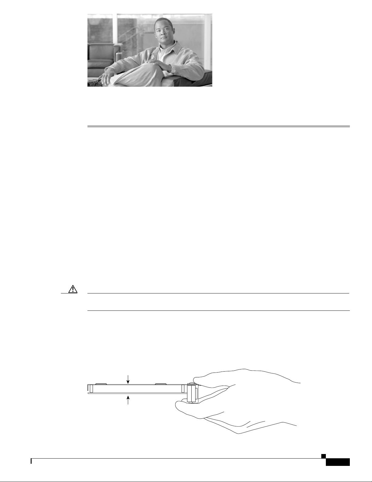
Caution Always handle the SPA by the carrier edges and handle; never touch the SPA components or connector
pins. (See Figure 5-1.)
When a slot is not in use, a SPA blank filler plate must fill the empty slot to allow the router or switch
to conform to electromagnetic interference (EMI) emissions requirements and to allow proper airflow
across the installed modules. If you plan to install a SPA in a slot that is not in use, you must first remove
the SPA blank filler plate.
Figure 5-1 Handling a SPA
Metal carrier
Printed circuit board
H6420
Release 12.0(32)SY1, OL-8831-01, Rev. G6, July 19, 2007
Cisco 12000 Series Router SIP and SPA Hardware Installation Guide
5-1
Page 2

SPA Installation and Removal
SPA Installation and Removal
This section provides step-by-step instructions for removing and installing a SPA in an SIP.
Chapter 5 Installing and Removing a Shared Port Adapter
Warning
When performing the following procedures, wear a grounding wriststraptoavoidESDdamagetothe
SPA. Some platforms have an ESD connector for attaching the wrist strap. Do not directly touch the
midplane or backplane with your hand or any metal tool, or you could shock yourself.
Installing a SPA in a SIP
To install a SPA in a SIP, refer to Figure 5-2 and do the following:
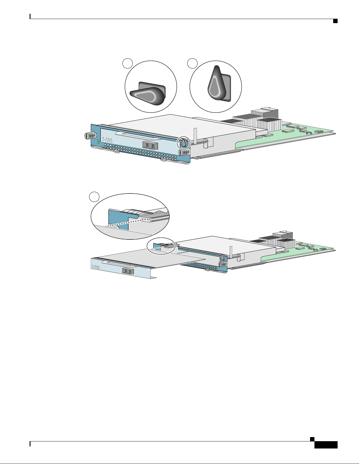
Step 1 To insert the SPA in the SIP, locate the guide rails inside the SIP that hold the SPA in place. They are at
the top left and top right of the SPA slot and are recessed about an inch, as shown in C of Figure 5-2.
Step 2 Carefully slide the SPA all the way in the SIP until the SPA is firmlyseatedintheSPAinterfaceconnector.
When fully seated, the SPA might be slightly behind the SIP faceplate.
Step 3 After the SPA is properly seated, turn the SPA lock to its locked and horizontal position, as shown in A
of Figure 5-2.
Removing a SPA from a SIP
To remove a SPA from a SIP, refer to Figure 5-2 and do the following:
Step 1 If attached, remove any cables from the SPA.
Step 2 To remove the SPA from the SIP, turn the SPA lock from its locked and horizontal position shown in A
of Figure 5-2 to its unlocked and vertical position shown in B of Figure 5-2.
Step 3 Grasp the handle of the SPA and pull the SPA from the SIP. (Ensure that you have already disconnected
the cables from the SPA before removing the SPA from the SIP).
5-2
Cisco 12000 Series Router SIP and SPA Hardware Installation Guide
Release 12.0(32)SY1, OL-8831-01, Rev. G6, July 19, 2007
Page 3
Chapter 5 Installing and Removing a Shared Port Adapter
Figure 5-2 SPA Installation and Removal
Online Insertion and Removal
7300-CC-PA
OIR
STATUS
7300 PA CARRIER
C
ENABLED
RX CELLS
RX CARRIER
RX ALARM
7300-CC-PA
A
B
ATM
7300-CC-PA
OIR
STATUS
7300 PA CARRIER
ENABLED
RX CELLS
RX CARRIER
RX ALARM
ATM
Online Insertion and Removal
Cisco 12000 series router SIPs and SPAs support online insertion and removal (OIR). SPAs can be
inserted or removed independently from the SIP. OIR of a SIP with installed SPAs is also supported.
Optical Device Installation and Removal
Any contamination of the fiber connection can cause failure of the component or failure of the whole
system. A particle that partially or completely blocks the core generates strong back reflections, which
can cause instability in the laser system. Inspection, cleaning, and reinspection are critical steps to take
before making fiber-optic connections.
84657
Release 12.0(32)SY1, OL-8831-01, Rev. G6, July 19, 2007
Cisco 12000 Series Router SIP and SPA Hardware Installation Guide
5-3
Page 4

Checking the Installation
Cleaning Optical Devices
See the Inspection and Cleaning Procedures for Fiber-Optic Connections document for information on
cleaning optical devices.
Checking the Installation
This section describes the procedures you can use to verify the SIP and SPA installation, and includes
information on the following topics:
• Verifying the Installation, page 5-4
• Using show Commands to Verify SIP and SPA Status, page 5-5
• Using show Commands to Display SPA Information, page 5-6
• Using the ping Command to Verify Network Connectivity, page 5-8
Verifying the Installation
Chapter 5 Installing and Removing a Shared Port Adapter
This section describes how to verify the SIP and SPA installation by observing the SIP LED states, SPA
LED states, and the information displayed on the console terminal.
When the system has reinitialized all interfaces, the SIP STATUS LED should be green (on) and the SPA
STATUS LEDs should be green (on). The port LEDs (C/A and A/L) may be green (on), depending on
your connections and configuration. The console screen also displays a message as the system discovers
each interface during its reinitialization.
Note A POS interface is used in the following examples for illustrative purposes.
The following sample display shows the events logged by the system as a SIP with a POS SPA was
removed from module slot 4 in the router. In this example, interface 0 (interface 4/0/0) on the POS SPA
was up and active when the SIP was removed from the router. Note that the system logs that the SIP card
was removed from slot 4 and that interface 4/0/0 is changed to down.
Router#
00:06:17:%WS_ALARM-6-INFO:ASSERT CRITICAL slot 4 Active Card Removed OIR Alarm
00:06:17:%OIR-6-REMCARD:Card removed from slot 4, interfaces disabled
00:06:18:%LINEPROTO-5-UPDOWN:Line protocol on Interface pos4/0/0, changed state to down
When you reinsert the SIP with the installed POS SPA, the system automatically brings up the interface
that was changed to down when the SIP was removed.
Router#
00:07:29:%OIR-6-INSCARD:Card inserted in slot 4, interfaces administratively shut down
00:07:32:%WS_ALARM-6-INFO:CLEAR CRITICAL slot 4 Active Card Removed OIR Alarm
00:07:35:%LINK-3-UPDOWN:Interface pos4/0/0, changed state to up
00:07:36:%LINEPROTO-5-UPDOWN:Line protocol on Interface pos4/0/0, changed state to up
5-4
Use the following procedure to verify that a SIP and SPA are installed correctly:
Cisco 12000 Series Router SIP and SPA Hardware Installation Guide
Release 12.0(32)SY1, OL-8831-01, Rev. G6, July 19, 2007
Page 5

Chapter 5 Installing and Removing a Shared Port Adapter
Step 1 Observe the console display messages and verify that the system discovers the SIP, while the system
reinitializes each interface, as follows:
• As a SIP is initialized, the STATUS LED will firstbe yellow,indicating that power is on, but the SIP
is being configured. When the SIP is active, the STATUS LED will illuminate green.
• SPAs will follow the same sequence once the SIP has completed its initialization. The SPASTATUS
LEDs will illuminate amber, turning to green when the SPAs become active.
• When the SIP and SPA STATUS LEDs are green, all associated interfaces are configurable.
Refer to the Cisco 12000 Series Router SIP and SPA Software Configuration Guide (Cisco IOS) for
configuration instructions.
• If a SIP or SPA is replaced with a module of the same type (as in an OIR or hardware swap), the
previous configuration will be reinstated when the SIP or SPA becomes active.
• If a SIP or SPA has not been previously installed in the same slot or subslot, then the configuration
for all associated interfaces will be empty.
Note New interfaces are not available until you configure them.
Checking the Installation
Step 2 If the SIPs and SPAs have not become active within three minutes, refer to the system console messages
as follows:
• If a SIP or SPA is undergoing an FPD upgrade, then console messages will indicate that the FPD
process has been initiated. The upgrade process might take several minutes. Use the show fpd
upgrade progress command to obtain information about the FPD process. SIPs or SPAs that
undergo an FPD upgrade will automatically be rebooted. Return to Step 1.
• If there is no indication that an FPD upgrade is underway, see Chapter 6, “Troubleshooting the
Installation.”
Using show Commands to Verify SIP and SPA Status
The following procedure uses show commands to verify that the new SPAs are configuredand operating
correctly.
Step 1 Use the show running-config command to display the system configuration. Verify that the
configuration includes the new SPA interfaces.
Step 2 Display all of the current SPAs and a summary of their status using the show hw-module subslot oir
command.
Step 3 Display information about the installed SIPs using the show diag command.
Step 4 Use the show hw-module subslot fpd command to verify the FPD version information of the SPAs
installed in the system.
Note If a SPA does not meet the minimum FPD version required, it will be updated automatically. If
the update fails, the failing module will be powered down and an error message will be reported
on the system console.
Release 12.0(32)SY1, OL-8831-01, Rev. G6, July 19, 2007
Cisco 12000 Series Router SIP and SPA Hardware Installation Guide
5-5
Page 6
Chapter 5 Installing and Removing a Shared Port Adapter
Checking the Installation
For more information about FPD upgrades, refer to the “Upgrading Field-Programmable
Devices” chapter of the Cisco 7600 Series Router SIP, SSC, and SPA Software Configuration Guide.
Step 5 Use the show version command to obtain a few details on the installed SIPs and interfaces available.
Using show Commands to Display SPA Information
Table 5-1 describes the show commands you can use to display SPA information.
Table 5-1 show Commands to Display SPA Information
Command Type of Information Provided
show running-config The router’s running configuration and interfaces available in the
system.
show hw-module subslot all oir The operational status of all SPAs in the system.
show diag SPA type in that slot, number of ports, hardware revision, part
number, and EEPROM contents.
show hw-module subslot all fpd FPD version information of SPAs in the system.
show version Cisco IOS software version, names and sources of configuration
files, and boot images.
Table 5-2 show Commands to Display SPA Information
Command Type of Information Provided Example
show controllers type
slot/subslot/port
show interfaces type
slot/subslot/port
Network link status, register contents, and
controller chip errors.
Line status and data link protocol status for a
particular SPA port. Statistics about data traffic
show controllers pos 2/3/0
show interfaces pos 2/2/0
sent and received by the port.
show diag slot SPA type in that slot, number of ports, hardware
show diag 4
revision, part number, and EEPROM contents.
show version Cisco IOS software version, names and sources of
show version
configuration files, and boot images.
Note A Fast Ethernet interface is used in the following examples for illustrative purposes.
The following sample display shows the events logged by the system as an SIP with a Fast Ethernet SPA
was removed from module slot 3; the system then reinitializes the remaining interface processors and
marks as down the Fast Ethernet interface on the SIP that was removed from slot 3.
Router#
18:04:29: %OIR-6-REMCARD: Card removed from slot 3, interfaces disabled
18:04:30: %LINEPROTO-5-UPDOWN: Line protocol on Interface FastEthernet3/0, changed state
to down
5-6
Cisco 12000 Series Router SIP and SPA Hardware Installation Guide
Release 12.0(32)SY1, OL-8831-01, Rev. G6, July 19, 2007
Page 7

Chapter 5 Installing and Removing a Shared Port Adapter
When you reinsert the SIP, the system automatically brings up the interfaces that were up
when the SIP was removed.
Router#
18:05:00: %OIR-6-INSCARD: Card inserted in slot 3, interfaces administratively shut down
18:05:08: %LINEPROTO-5-UPDOWN: Line protocol on Interface FastEthernet3/0, changed state
to up
Note When a new SIP is inserted or when a SIP is moved to a new slot, the system recognizes the new
interfaces but leaves them in the shutdown state until you configure them and change their state to up.
The following sample display shows the events logged by the system as you insert a new SIP in module
slot 3.
Router#
18:05:25: %LINEPROTO-5-UPDOWN: Line protocol on Interface FastEthernet3/1, changed state
to down
Use the following procedure to verify that the SIP is installed correctly:
Checking the Installation
Step 1 Observe the console display messages and verify that the system discovers the SIP, while the system
reinitializes each interface, as follows:
• If you installed a new SIP, the STATUS LED should be on (green). The system should recognize all
new interfaces but leave them configured as down.
• If you replaced a SIP, the STATUS LED should be on (green). The system does not recognize each
interface and places it in the administratively down state.
Step 2 Verify that the ENABLED LED on the SPA goes on (is green) and remains on after the reinitialization
is complete. If the ENABLED LED remains on, proceed to Step 5. If the ENABLED LED does not
remain on, proceed to Step 3.
Step 3 If the ENABLED LED on a SPA fails to go on, the SPA or the SIP might not be fully seated even if the
SPA lock is in the locked and horizontal position. When a SPA is not recognized, the SIP is deactivated,
and its OIR LED is yellow.
• Remove the SIP from the router.
• Remove the SPA from the SIP.
• Inspect the SIP and the SPA. Verify there are no bent pins or parts and that there is nothing lodged
in the two devices that could prevent a good connection.
• Insert the SPA in the SIP by sliding the SPA all the way in the SIP until the SPA is firmly seated in
the SPA interface connector. When fully seated in the SIP, the SPA might be slightly behind the SIP
faceplate.
• Insert the SIP into the router.
• After the system reinitialization, the ENABLED LED on the SPA should go on and remain on. If the
ENABLED LED remains on, proceed to Step 5. If it does not, proceed to Step 4.
Step 4 If the ENABLED LED on a SPA still fails to go on, remove the SIP and install it in another available
slot on the router.
• If the ENABLED LED goes on, suspect a failed backplane port in the original slot.
• If the ENABLED LED fails to go on, remove the SIP and ensure the SPA is firmly seated in its slot.
Remove and reinstall it accordingly.
Release 12.0(32)SY1, OL-8831-01, Rev. G6, July 19, 2007
Cisco 12000 Series Router SIP and SPA Hardware Installation Guide
5-7
Page 8

Checking the Installation
Step 5 If the SPA is new and not a replacement, configure the new SPA using the Cisco 12000 Series Router
Step 6 If the SIP is a replacement, use the show interfaces type slot-number/port-number command or the
Step 7 When the interfaces are up, check the activity of each SPA by observing the status LEDs.
Step 8 If an interface LED fails to go on and a cable is connected to the interface port, check the cable
Step 9 Repeat Step 1 through Step 8 to verify that any additional MSCs are properly installed.
Chapter 5 Installing and Removing a Shared Port Adapter
• If the ENABLED LED still fails to go on, but other LEDs on the SIP SPA go on to indicate activity,
proceed to Step 5 to resume the installation checkout; suspect that the ENABLED LED on the SPA
has failed. Contact a service representative to report the problem and obtain further instructions.
• If no LEDs on the SPA go on:
–
Verify that the SPAis supported on the SIP and that it has the required hardware revision. If the
SPA is not supported or has an old hardware revision, the show diag command indicates that
the SIP is deactivated.
–
Suspect a faulty SIP. Contact a service representative to report the problem and obtain further
instructions.
SIP and SPA Software Configuration Guide (Cisco IOS).
Note New interfaces are not available until you configure them.
show controllers command to verify the status of the SPAs. (See the “Using show Commands to Verify
SIP and SPA Status” section on page 5-5.)
If you replaced a SIP with another SIP with a different SPA installed, the system recognizes the
interfaces on the previously configured SPA but does not recognize the new SPA interfaces. The new
interfaces remain in the shutdown state until you configure them.
connection and make certain it is properly seated in the connector.
If you experience other problems that you are unable to solve, contact TAC (see the “Obtaining
Documentation” section on page -xv in the Preface) or a service representative for assistance.
To configure the new interface, use the Cisco 12000 Series Router SIP and SPA Software Configuration
Guide (Cisco IOS).
Using the ping Command to Verify Network Connectivity
This section provides brief descriptions of the ping command. The ping command allows you to verify
that a SPA port is functioning properly and to check the path between a specific port and connected
devices at various locations on the network. After you verify that the system and the SIP have booted
successfully and are operational, you can use this command to verify the status of the SPA ports. Refer
to the publications listed in the “Related Documentation” section on page xv for detailed command
descriptions and examples.
The ping command sends an echo request out to a remote device at an IP address that you specify.After
sending a series of signals, the command waits a specifiedtime for the remote device to echo the signals.
Each returned signal is displayed as an exclamation point (!) on the console terminal; each signal that is
not returned before the specified timeout is displayed as a period (.). A series of exclamation points
(!!!!!) indicates a good connection; a series of periods (.....) or the messages [timed out] or [failed]
indicate that the connection failed.
Following is an example of a successful ping command to a remote server with the IP address 10.1.1.60:
5-8
Cisco 12000 Series Router SIP and SPA Hardware Installation Guide
Release 12.0(32)SY1, OL-8831-01, Rev. G6, July 19, 2007
Page 9

Chapter 5 Installing and Removing a Shared Port Adapter
Router# ping 10.1.1.60 <Return>
Type escape sequence to abort.
Sending 5, 100-byte ICMP Echoes to 10.1.1.60, timeout is 2 seconds:
!!!!!
Success rate is 100 percent (5/5), round-trip min/avg/max = 1/15/64 ms
Router#
If the connection fails, verify that you have the correct IP address for the server and that the server is
active (powered on), and repeat the ping command.
Table 5-3 show Commands to Display SPA Information
Command Type of Information Provided Example
show controllers type
slot/subslot/port
show interfaces type
slot/subslot/port
Network link status, register contents, and
controller chip errors.
Line status and data link protocol status for a
particular SPA port. Statistics about data traffic
show controllers pos 2/3/0
show interfaces pos 2/2/0
sent and received by the port.
show diag slot SPA type in that slot, number of ports, hardware
show diag 4
revision, part number, and EEPROM contents.
show version Cisco IOS software version, names and sources of
show version
configuration files, and boot images.
.SPA Blank Filler Plates
.SPA Blank Filler Plates
SPA blank filler plates are available to fill an unused SPA subslot. A special SPA blank filler plate is
preinstalled for the 7600-SIP-600 bay 1.
When a SPAsubslot is not in use, a SPA blank fillerplate must be installed in the empty subslot to allow
the router or switch to conform to electromagnetic interference (EMI) emissions requirements and to
allow proper airflow across the SPAs. If you plan to install a new SPA in a subslot that is not in use, you
must first remove the SPA blank filler plate.
Release 12.0(32)SY1, OL-8831-01, Rev. G6, July 19, 2007
Cisco 12000 Series Router SIP and SPA Hardware Installation Guide
5-9
Page 10
SPA Cable-Management Brackets
SPA Cable-Management Brackets
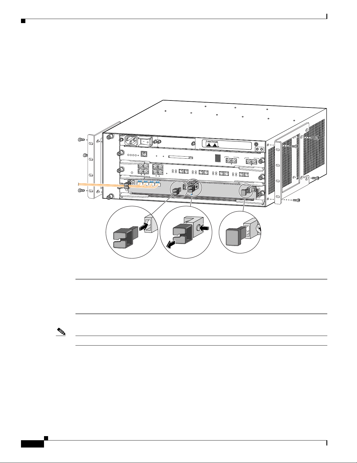
SPAs are shipped with an accessory kit that includes cable-management brackets. Figure 5-3 shows
cable-management brackets installed in a SPA, as well as cable routing.
Figure 5-3 SPA Cable-Management Brackets
WS-X6K-SUP2-2GE
FAN
STATUS
1
STATUS
SYSTEM
CONSOLE
PWR MGMT
RESET
CONSOLE
PORT
MODE
OSM-4OC12 POS-SI
4 PORT OC-12 POS SM IR
0
STATUS
2
CONSOLE
1
3
2
STATUS
4
LINK
1
2
LINK
LINK
3
4
0
C/A
A/L
LINK
0
C/A
A/L
0
C/A
A/L
0
C/A
A/L
PCMCIA EJECT
RX
ACTIVE
TX
RX
RESET
CARRIER
ALARM
SUPERVISOR2
2
7600-MSC-600
3
MODULAR
SERVICES CARD
PORT 1
STATUS
SPA-4XOC3-ATM
Chapter 5 Installing and Removing a Shared Port Adapter
Switch Load
100%
PORT 1
1%
TX
RX
ACTIVE
TX
ACTIVE
TX
RX
CARRIER
PORT 2
ALARM
CARRIER
ALARM
LINK
RX
TX
TX
RX
PORT 3
CARRIER
ALARM
PORT 2
LINK
RX
ACTIVE
TX
TX
RX
PORT4
1
STATUS
3
129582
5-10
To install cable-management brackets on a SPA, perform the following steps:
Step 1 Screw the two pull assemblies into both sides of the SPA.
Step 2 Insert the cable-management clip into the slot.
Step 3 To remove the cable-management clip, depress the button on the clip and pull it out.
Note Blank filler plugs are provided if no cable-management clips are installed.
Cisco 12000 Series Router SIP and SPA Hardware Installation Guide
Release 12.0(32)SY1, OL-8831-01, Rev. G6, July 19, 2007
 Loading...