

Page 1

Doc. No.
78-3610-09
Cisco IOS Release 11.0 BT Release Note and
Update to Configuration Guides and Command
References
January 15, 1999
This document supplements the Cisco IOS Release 11.0 documentation set with new and changed
commands that support Cisco IOS Release 11.0(10)BT and later. Note that Cisco IOS Release
11.0(10)BT is the initial release of Cisco IOS Release 11.0 BT. No prior versions of Cisco IOS
Release 11.0 BT exist. The TN3270 server function is supported on a Channel Interface Processor
card in a Cisco 7000 series or Cisco 7500 series router. The following Cisco IOS releases are
covered by this release note publication:
• Cisco IOS 11.0(10)BT
• Cisco IOS 11.0(11)BT
Corporate Headquarters
Cisco Systems, Inc.
170 West Tasman Drive
San Jose, CA 95134-1706
USA
Copyright © 1998
Cisco Systems, Inc.
All rights reserved.
• Cisco IOS 11.0(12)BT
• Cisco IOS 11.0(13a)BT
Note Cisco IOS Release 11.0(13)BT was renumbered and released as 11.0(13a)BT.)
• Cisco IOS 11.0(14)BT, Cisco IOS 11.0(14a)BT1
Note Shipment of Cisco IOS Release 11.0(14)BT was halted due to CSCdj05366. A fix was
implemented and the release was renumbered and released as 11.0(14a)BT1.
1
Page 2

Introduction
Introduction
• Cisco IOS 11.0(15)BT
• Cisco IOS 11.0(16)BT
• Cisco IOS 11.0(17)BT
• Cisco IOS 11.0(18)BT
• Cisco IOS 11.0(19)BT
• Cisco IOS 11.0(20)BT
• Cisco IOS 11.0(21)BT
• Cisco IOS 11.0(22)BT
Cisco IOS Release 11.0 BT is based on Cisco IOS Release 11.0.
This Release Note and Update is divided into the following sections:
• Release Note, page 2
— Platform Support, page 3
Release Note
— Cisco IOS Packaging, page 3
— Boot ROM Requirements, page 3
— CIP Boot Image Requirements, page 3
— Memory Requirements, page 3
— Microcode Software, page 4
— New Software Features in 11.0(10)BT, page 4
• Update to Configuration Guide, page 4
• Update to Command Reference, page 19
• Cisco Connection Online, page 57
• Cisco Connection Documentation, page 57
Use this document in conjunction with the Router Products Release Notes for Cisco IOS
Release 11.0 and the Cisco IOS Release 11.0 configuration guide and command reference
publications,specificallytheRouterProductsConfigurationGuideChapters 1 to 6, Router Products
Configuration Guide Chapters 22 to 33, Router Products Command Reference Chapters 1 to 6,
Router Products Command Reference Chapters 22 to 33.
Cisco IOSRelease 11.0 BT introduces TN3270 server support on Channel Interface Processor (CIP)
cards.
Note To enable the TN3270 server feature, you must have a CIP card installed in a Cisco 7000
series router or Cisco 7500 series router. The TN3270 server is different from the TN3270 terminal
emulation access feature described in the “Configuring TN3270” chapter of the Access and
Communication Servers Configuration Guide.
2 Cisco IOS Release 11.0 BT Release Note and Update to Configuration Guides and Command References
Page 3

Platform Support
Cisco IOS Release 11.0 BT supports the following router platforms:
• Cisco 7500 series
• Cisco 7000 series and Cisco 7000 series with RSP7000
Cisco IOS Packaging
The following feature sets are available in Release 11.0 BT. Refer to the Router Products Release
NotesforCisco IOS Release 11.0 for a list of the features provided in the Cisco 7000 andCisco 7500
series feature sets.
• Enterprise (this feature set includes CIP)
• Enterprise/CIP2
Boot ROM Requirements
Boot ROMs that support Cisco IOS Release 11.0 are required. No special requirements exist for
Cisco IOS Release 11.0 BT.
Release Note
CIP Boot Image Requirements
The CIP boot image is bundled in the Cisco IOS Release 11.0 BT image. Youmust have the image
that supports your CIP or your CIP2 hardware. You cannot run a CIP and a CIP2 card in the same
router. See Table 1 for a list of image names and supported CIP or CIP2 cards.
Table 1 11.0 BT Image Names for CIP and CIP2 Hardware
Image Names Supported CIP Hardware
rsp-k-mz CIP
rsp-k2-mz CIP2
gs7-k-mz CIP
gs7-k2-mz CIP2
Memory Requirements
The memory requirements for Cisco IOS 11.0 BT are shown in Table 2. The CIP supports up to
128 Mb of memory.
Table 2 11.0 BT Memory Requirements
Cisco 7500 Series
and Cisco 7000
with RSP7000
Enterprise Set
(rsp-k-mz)
Enterprise/CIP2 Set
(rsp-k2-mz)
Cisco IOS Release 11.0 BT Release Note and Update to Configuration Guides and Command References 3
MinimumRequired
Code Memory
8 MB Flash memory
card
8 MB Flash memory
card
Required Main
Memory
24 Mb 32 Mb RAM
24 Mb 32 Mb RAM
Required CIP
Memory
Release11.0
Runs From
Page 4

Update to Configuration Guide
Cisco 7500 Series
and Cisco 7000
with RSP7000
Cisco 7000 Series
Enterprise Set
(gs7-k-mz)
Enterprise/CIP2 Set
(gs7-k2-mz)
MinimumRequired
Code Memory
8 MB Flash memory
card
8 MB Flash memory
card
Microcode Software
Note that microcode software images are bundled with the system software image. Bundling
eliminates the need to store separate microcode images. When the router starts up, the system
software unpacks the microcode software bundle and loads the proper software on all the interface
processor boards.
New Software Features in 11.0(10)BT
The TN3270 server is a new feature on the CIP of the Cisco 7000 family of routers. The TN3270
server allows TN3270 clients access to IBM and IBM-compatible mainframes. It can reduce the
cycles spent by the mainframe on TCP/IP and TN3270 processing by a factor of ten or more and
off-load the TCP/IP and TN3270 cycles from the mainframe.
Required Main
Memory
Required Code
Memory
16 Mb 32 Mb RAM
16 Mb 32 Mb RAM
Required CIP
Memory
Required CIP
Memory
Release11.0
Runs From
Release11.0
Runs From
The TN3270 server supports up to 8000 (CIP1) or up to 16000 (CIP2) concurrent sessions, while
most external gateway solutions can support only 1000 to 2000 sessions. The TN3270 server offers
the following capabilities:
• Load Balancing and Redundancy—Provides effective CIP resource utilization and more
consistent response times. (This feature is initially provided by means of an external, prototype
implementation.)
• End-to-End Session Visibility—Provides enhanced resource management.
• Systems Network Architecture (SNA) Session Switching—Off-loads VTAM by providing
session routing.
• TN3270E Support—In combination with a TN3270E client, provides advanced SNA
management and SNA functionality, including printer support.
• Dynamic Definition of Dependent Logical Units (LU)—Provides simplified configuration and
network definition at the router and in VTAM.
• Dynamic Allocation of LUs—Makes efficient use of LU pool resources while supporting
multiple SNA model types.
TN3270 server requires 32 MB of CIP dynamic RAM to support up to 4000 sessions, 64 MB to
support 8000 sessions, and 128 MB to support 16000 sessions (CIP2 only). TN3270 server can run
concurrently with any of the other CIP applications (IP Datagram, TCP/IP Offload, or CIP SNA
(CSNA)), but operation of any of these features will affect the total number of sessions supported
because of contention for CIP processor cycles.
Update to Configuration Guide
The information that follows is an update to the Router Products Configuration Guide, Chapters 23
to 33. Add the TN3270 information as a standalone chapter following page 33-22.
4 Cisco IOS Release 11.0 BT Release Note and Update to Configuration Guides and Command References
Page 5
Cisco’s Implementation of TN3270 on a Channel Interface Processor
Configuring TN3270 Server on the Channel
Interface Processor
This chapter describes TN3270 server support provided by the Channel Interface Processor (CIP)
card for Systems Network Architecture (SNA) devices. For a complete description of the commands
mentioned in this chapter, refer to the “TN3270 Server Commands” update chapter.
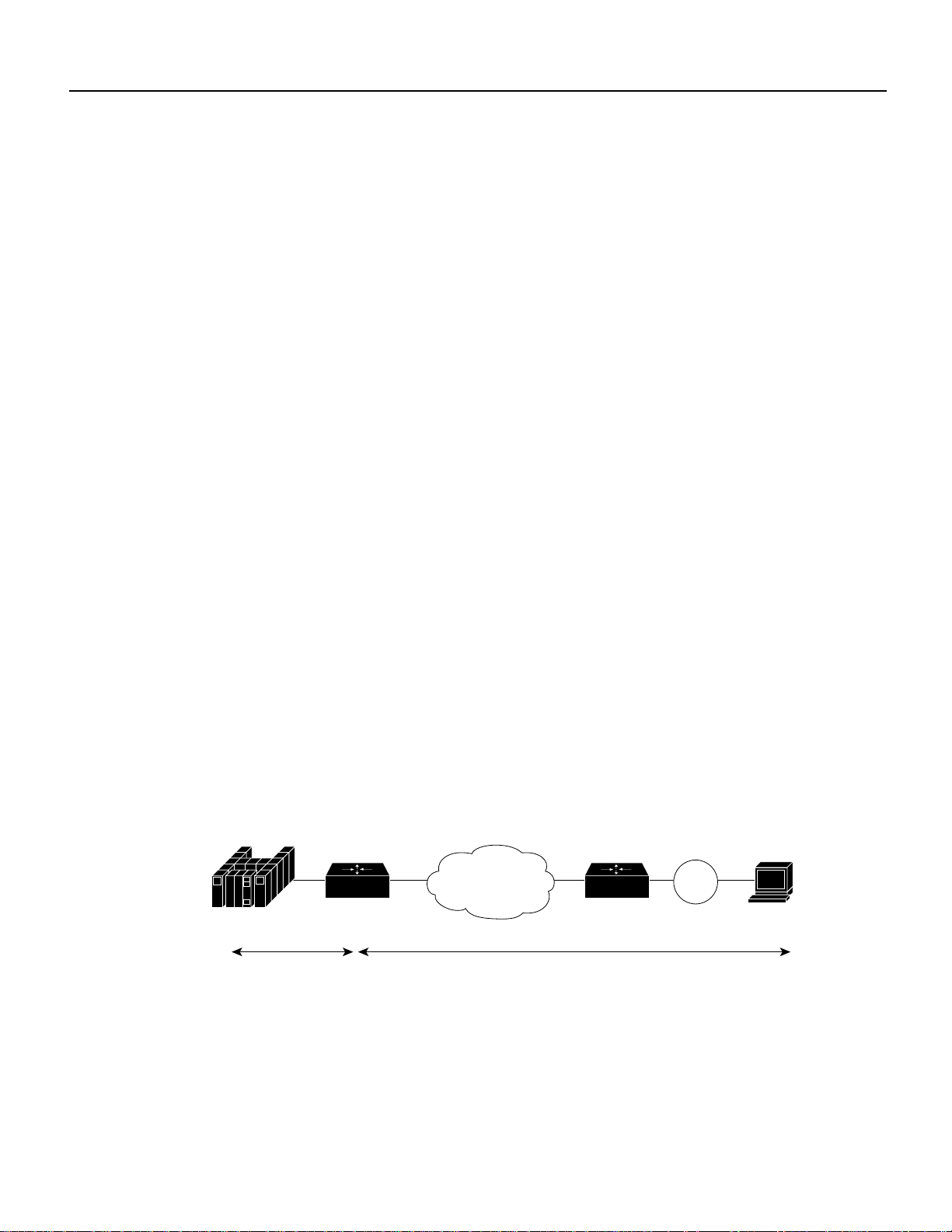
Cisco’s Implementation of TN3270 on a Channel Interface Processor
The TN3270 server feature on a CIP card provides mapping between an SNA 3270 host and a
TN3270clientconnectedtoaTCP/IPnetworkasshownin Figure 1. Functionally,itisusefulto view
the TN3270 server from two different perspectives: SNA functions and Telnet Server functions.
• SNA Functions
From the perspective of an SNA 3270 host connected to the CIP, the TN3270 server is an SNA
device that supports multiple physical units (PUs), with each PU supporting up to 255 logical
units (LUs). The LU can be Type 1, 2, or 3. The SNA host is unaware of the existence of the
TCP/IP extension on the implementation of these LUs.
The LUs implemented by TN3270 server are dependent LUs. To route these dependent LU
sessions to multiple virtual telecommunications access method (VTAM) hosts connected to the
server in the CIP card, rather than routing in the VTAM hosts, the TN3270 server implements a
SNA session switch with end node dependent LU requester (DLUR) function. Using the DLUR
isoptionalsothattheTN3270servercan be used with VTAMversions prior to version4.2,which
provide no APPN support.
SNA session switch allows you to eliminate SNA subarea routing between hosts of TN3270
traffic by establishing APPN links with the primary LU hosts directly.
• Telnet Server Functions
From the perspective of a TN3270 client, the TN3270 server is a Telnet server that can support
approximately 8000 (CIP1) or 16000 (CIP2) concurrent Telnet sessions. The server on the CIP
card supports Telnet connection negotiation and data format as specified in RFC 1576 (referred
to as “traditional TN3270”) and RFC 1647 (referred to as “TN3270E”).
Figure 1 TN3270 Implementation
Router Router
SNA TCP/IP
Because the TN3270 server configuration is performed after an interface is configured for CIP SNA
(CSNA)support, TN3270 configuration issues and tasks are addressed separately from the interface
configuration tasks. The description of TN3270 configuration issues and tasks begins in the section
“Configuring TN3270 on a Channel Interface Processor,” later in this chapter.
Token
Ring
S4735
TN3270
client
Configuring TN3270 Server on the Channel Interface Processor 5
Page 6

Configuring TN3270 on a Channel Interface Processor
Note To enable the TN3270 server feature, you must have a CIP installed in a Cisco 7000 family
router.The TN3270 server is different from the TN3270 terminal emulation access feature described
in the “Configuring TN3270” chapter of the Access Services Configuration Guide.
Configuring TN3270 on a Channel Interface Processor
The following sections describe additional features of TN3270 server support on the CIP. The
features discussed include the following:
• Dynamic LU Allocation
• Formation of LU Model Type and Number
• Specific LU Allocation
• SNA Session Switch—End Node DLUR
• Multiple Hosts Support
You will also need to understand the following information before proceeding with TN3270
configuration tasks:
• VTAM Host Configuration Considerations for Dynamic LU Allocation
• TN3270 Configuration Modes
Dynamic LU Allocation
This will be the most common form of request from TN3270 clients emulating a TN3270 terminal.
The user typically wants to specify emulating a particular terminal type and normally is not
interested in what LOCADDR or LU name is allocated by the host, as long as a network solicitor
logon menu is presented. The server will perform the following on such a session request:
• Form an EBCDIC string based on the model type and number requested by the client (see
“FormationofLU Model Typeand Number” for the algorithm used). This string is used as a field
in a Reply product set ID (PSID) network management vector transport (NMVT).
• Allocate a LOCADDR from the next available LU in the generic LU pool. This LOCADDR is
used in the NMVT.
• Send the formatted Reply PSID NMVT to VTAM.
When VTAMreceives the NMVT,it will use the EBCDIC model type and number string to look up
an LU template under the LUGROUP. For example, the string “327802E” will find a match in the
sample configuration shown in Figure 2. An ACTLU will be sent and a terminal session with the
model and type requested by the client is established.
Formation of LU Model Type and Number
VTAM requires a model type and number from the Reply PSID NMVT to use as a key to look up in
the LU group to find an LU template. The model type is a four character string; the model number
is a two or three character string. The server will accept the following formats of terminal type string
from the client:
• IBM-<XXXX>-<Y>[-E]: This will be formatted as “XXXX0Y”or “XXXX0YE” in the model
type and number field in the Reply PSID NMVT.
6 Configuring TN3270 Server on the Channel Interface Processor
Page 7

Configuring TN3270 on a Channel Interface Processor
• IBM-DYNAMIC: This will result in “DYNAMIC”being put in the model type and number field.
The VTAM configuration will need to have “DYNAMIC”defined as a template in the LU group.
In fact “IBM-ZZ..Z,” where “ZZ..Z” does not match the preceding syntax, will be forwarded as
“ZZ..Z.”
Note The “E” in the model string refers to 3270 extended datastream. It has no connection with
the “E” in “TN3270E”.
• Any other string is forwarded as is.
• In all cases, the string forwarded is translated from ASCII to EBCDIC and truncated at seven
characters.
A complication arises with TN3270E clients that request a copy of the BIND-IMAGE. Such clients
require system control services (SCS) datastream on the system services control point (SSCP)-LU
flow. All other clients require 3270 datastream on that flow. Therefore, these two kinds of client
must be directed to different LUGROUP entries at the host. To make this as easy as possible, the
SCS requirement is also encoded into the model string sent to the host. Following the previously
described terminal type string formats accepted by the server, this additional condition is applied:
• If the client has negotiated to receive BIND-IMAGE, the character “S” is overlaid on the fifth
character of the string, or appended if the string is less than five characters. (See Table 3.)
Table 3 Examples of Model String Mapping
String from client (ASCII)
IBM-3278-4 No 327804
IBM-3279-5E No 327905E
IBM-3279-3-E Yes 3279S5E
IBM-DYNAMIC Yes DYNASIC
ABC Yes ABCS
ABCDEFGH Yes ABCDSFG
Specific LU Allocation
A TN3270E client can request a specific LU name by using the TN3270E command CONNECT as
documented in RFC 1647. The name requested must match the name by which the TN3270 server
knowsthe LU (see the section “LU Names in the TN3270 Server”), and the host must have activated
the LU (with ACTLU).
LU Names in the TN3270 Server
Where SNA session switching is configured (that is, on DLUR PUs) the TN3270 server learns the
LU names from the ACTLUs.
BIND-IMAGE
requested? String to Host (EBCDIC)
For direct PUs, a “seed” name can be configured on the PU. The TN3270 server uses this name in
conjunction with the LOCADDRS to generate names for the LUs. It is best to use the same naming
convention as the host, if possible.
Configuring TN3270 Server on the Channel Interface Processor 7
Page 8

VTAM Host Configuration Considerations for Dynamic LU Allocation
SNA Session Switch—End Node DLUR
An end node DLUR function is implemented as part of the TN3270 server. The purpose of the
DLUR is to allow the routing of TN3270 LUs to multiple VTAM hosts to be performed in the CIP
card rather than on the VTAM hosts. The need for this feature will increase with the introduction of
the new multi-CPU CMOS mainframe which comprises up to 16 CPUs that appear as separate
VTAMs.
The implementation of TN3270 server LUs under DLUR also allows the server to learn about the
LU names on the ACTLU, which greatly simplifies the configuration to support specifically
requested LUs such as printers.
Multiple Hosts Support
The TN3270 server supports access to multiple hosts via the configuration on a PU basis (Table 4).
PUs connected to different hosts or applications can be configured with different IP address.
Table 4 Direct PU Configuration in Router
Adapte
CommandPU
Name IDBLK IP-address Type
pu X1 05D30001 192.195.80.40 tok 1 4 rmac 4100.cafe.0001 lu-seed TN3X1###
pu X2 05D30002 171.69.176.43 tok 1 8 rmac 4100.cafe.0002 lu-seed TN3X2###
r
number LSAP RMAC RMAC LU-seed LU-name
From the pu (direct) TN3270 configuration command values shown in Table 4, PU X2 establishes
a link to a host at SAP 8 on MAC address 4100.cafe.0002. A client connecting to IP address
171.69.176.43 is allocated an LU from that PU and is routed to that host.
Note that by using the DLUR function, all the LUs in the server can be defined and owned by a
controlling VTAM. When a client requests an application residing on a different VTAM host, the
controlling VTAM will issue the request to the target host which will send a BIND directly to the
client. All LU-LU data will then flowdirectly between the target host and the client without needing
to go through the controlling VTAM.
VTAM Host Configuration Considerations for Dynamic LU Allocation
Other non-Cisco implementations of TN3270 support depend on predefined, static pools of LUs to
support different terminal types requested by the TN3270 clients. The CIP TN3270 server
implementation removes the static nature of these configurations by using a VTAM release 3.4
feature, dynamic definition of dependent LU (DDDLU). (Refer to the VTAM operating system
manuals for your host system, under the descriptions for LUGROUP for additional information.)
DDDLU dynamically requests LUs using the terminal type provided by TN3270 clients. The
dynamic request eliminates the need to define any LU configuration in the server to support TN3270
clients emulating a generic TN3270 terminal.
TosupportDDDLU, the PUs used by the TN3270 server havetobedefinedinVTAM with LUSEED
and LUGROUP parameters as shown in Figure 2.
8 Configuring TN3270 Server on the Channel Interface Processor
Page 9

VTAM Host Configuration Considerations for Dynamic LU Allocation
Figure 2 VTAM Host Values Defining LUSEED and LUGROUP
Example VTAM host values defining LUSEED and LUGROUP name parameters:
TN3270PU PU .
IDBLK=05D,
IDNUM=30001,
LUSEED=TN3X1###, * define the seed component of the LU names
LUGROUP=AGROUP * define the LU group name
*
TN3X1100 LU LOCADDR=100,
MODETAB=AMODETAB
*
TN3X1101 LU LOCADDR=101,
DLOGMODE=M3287CS
Example VTAM host values defining LUGROUPname, AGROUP:
AGROUP LUGROUP * define LU group to support various
327802E LU USSTAB=USSXXX,
LOGAPPL=TPXP001,
DLOGMOD=SNX32702,
SSCPFM=USS3270
3278S2E LU USSTAB=USSYYY,
LOGAPPL=TPXP001,
DLOGMOD=SNX32702,
SSCPFM=USSSCS
327805 LU USSTAB=USSXXX,
LOGAPPL=TPXP001,
DLOGMOD=D4C32785,
SSCPFM=USS3270
@ LU USSTAB=USSXXX,
LOGAPPL=TPXP001,
DLOGMOD=D4A32772,
SSCPFM=USS3270
* define other PU parameters
created by DDDLU (e.g. LOCADDR 42 will have
the name TN3X1042)
* define a terminal which requires a
specific LU name
* define a printer which requires a specific
LU name
terminal types
* define template to support IBM 3278
terminal model 2 with Extended Data
Stream. Note that the USS messages in
USSXXX should be in 3270 datastream.
* define template to support IBM 3278
terminal model 2 with Extended Data
Stream, for TN3270E clients requesting
BIND-IMAGE.
* define template to support IBM 3279
terminal model 5
this is the default template to match any
other terminal types
Withthe configuration shown in Figure 2 defined in the host, the ACTPU sent by VTAMfor the PU
TN3270PU will have the “Unsolicited NMVT Support” set in the system services control point
(SSCP) capabilities control vector. This allows the PU to dynamically allocate LUs by sending
NMVT with a “Reply Product Set ID” control vector.
After the TN3270 server sends a positive response to the ACTPU, it will wait for VTAM to send
ACTLUs for all specifically defined LUs. In the sample configuration shown in Figure 2, ACTLUs
will be sent for TN3X1100 and TN3X1101. The server sends a positive response and sets SLU
DISABLED. The LOCADDR of these LUs are put into the specific LU cache and reserved for
specific LU name requests only.
To allow sufficienttime for the VTAMhost to send all the ACTLUs,a30-second timer is started and
restarted when an ACTLU is received. When the time expires, it is assumed all ACTLUs defined in
VTAM for the PU havebeen sent. All LUs that have not been activatedare availablein a generic LU
pool to be used for DDDLU unless they have been reserved by the configuration using the
generic-pool deny TN3270 configuration command.
Configuring TN3270 Server on the Channel Interface Processor 9
Page 10

TN3270 Configuration Modes
After the VTAM activation, the server can support session requests from clients using dynamic or
specific LU allocation.
TN3270 Configuration Modes
The TN3270 configuration modes and router command prompts are described in the following
sections and displayed in Figure 3. The TN3270 server can be configured only on Port 2, the internal
LAN port, of a CIP card.
Some configuration commands create entities on the CIP. For most of these, the command changes
to the mode associated with that entity (for example, a PU). In general, the parameters provided to
create the entity come in two sets: those which identify the specific instance of the entity (for
example,a PU name) and those that merely set operating parameters. To return to the mode later,the
same command is used but with only the first set of parameters. The following example tasks clarify
how to return to a command mode without necessarily creating a new entity:
To create a DLUR LSAP and enter DLUR LSAP configuration mode, perform the following task
beginning in TN3270 DLUR configuration mode:
Task Command
Create a DLUR LSAP and enter DLUR LSAP
configuration mode.
lsap token-adapter 1 84
To return later to the DLUR LSAP configuration mode on the same entity, perform the following
task beginning in TN3270 DLUR configuration mode:
Task Command
Enter DLUR LSAP configuration mode on the
same LSAP.
To remove an entity, the same identification parameters are needed. Perform the following task
beginning in TN3270 DLUR configuration mode:
Task Command
Remove a previously defined DLUR LSAP entity. no lsap token-adapter 1
TN3270 configuration modes described in this section include the following:
lsap token-adapter 1
• TN3270 Server Configuration Mode
• DLUR Configuration Mode
• DLUR SAP Configuration Mode
• PU Configuration Mode
• Commands Allowed in Multiple Modes
10 Configuring TN3270 Server on the Channel Interface Processor
Page 11
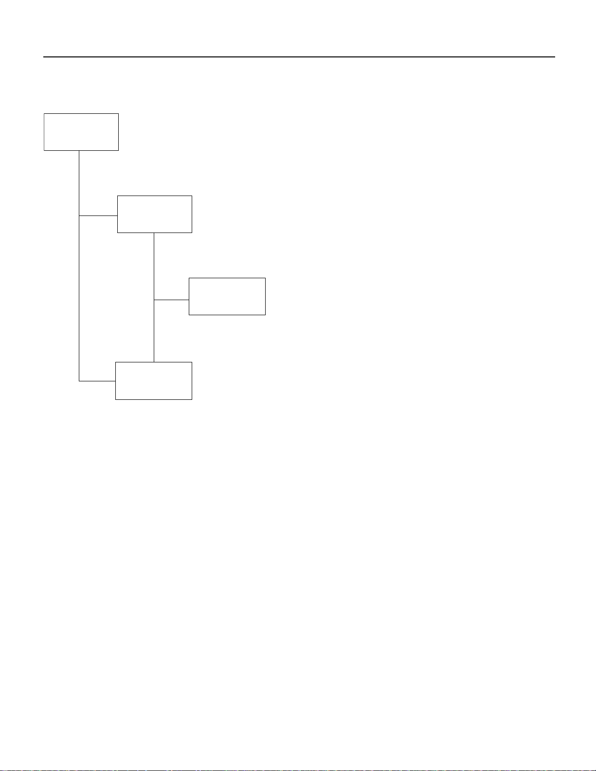
Figure 3 TN3270 Configuration Modes
TN3270 Configuration Modes
TN3270
configuration
mode
TN3270 DLUR
configuration
mode
TN3270/PU
TN3270 DLUR PU
configuration mode
TN3270 DLUR SAP
configuration
mode
Prompt:
tn3270-server>
Prompt:
tn3270-dlur>
Prompt:
tn3270-dlur-lsap>
Prompts:
tn3270-pu>
tn3270-dlur>
TN3270 Server Configuration Mode
From interface configuration mode, tn3270-server command puts you in TN3270 server
configuration mode.
Prompt:
tn3270-server>
DLUR Configuration Mode
From TN3270 server configuration mode, the dlur command puts you in DLUR configuration
mode.
Prompt:
tn3270-dlur>
Use TN3270 PU configuration mode when
the TN3270 server is attached to a non-APPN
host.
Use TN3270 DLUR PU configuration mode
when the TN3270 server is attached to an
APPN host.
S4736
Configuring TN3270 Server on the Channel Interface Processor 11
Page 12

TN3270 Configuration Modes
DLUR SAP Configuration Mode
From DLUR server configuration mode, lsap command puts you in DLUR SAP configuration mode.
Prompt:
tn3270-dlur-lsap>
PU Configuration Mode
There are two paths to PU configuration mode: from the TN3270 serverconfiguration mode, or from
the DLUR configuration mode. In either mode, the pu command puts you in PU configuration mode.
From TN3270 configuration mode, the pu command to create a new PU is:
pu pu-name idblk-idnum ip-address type adapno lsap [rmac rmac] [rsap rsap] [lu-seed
lu-name-stem]
From DLUR configuration mode, the pu command to create a new PU is:
pu pu-name idblk-idnum ip-address
From either mode, to return to PU configuration mode on PU pu-name the command is:
pu pu-name
Prompts:
tn3270-pu>
tn3270-dlur-pu>
Commands Allowed in Multiple Modes
The following commands are valid in TN3270 configuration mode, or in either variation of PU
configuration mode:
[no] tcp-port port-number
[no] idle-time seconds
[no] keepalive seconds
[no] unbind-action {keep | disconnect}
[no] generic-pool {permit | deny}
[no] shutdown
Values entered in PU configuration mode override settings made in TN3270 configuration mode. In
addition, the no form of these commands entered in PU configuration mode will restore the
command value entered in TN3270 command mode.
12 Configuring TN3270 Server on the Channel Interface Processor
Page 13

TN3270 Configuration Task List
The following sections describe how to configure TN3270 server support on the CIP. Not all tasks
are required. Refer to “TN3270 Configuration Example” for configuration examples.
Note The TN3270 server is configured on an internal LAN interface in the CIP, which is port 2 of
a CIP. Port 0 and port 1 represent physical interface ports; port 2 is a “virtual” port and is always
reserved for the internal LAN interface.
Task List for Multiple APPN Hosts
When the host site uses APPN and the TN3270 server can reach multiple hosts, we recommend you
use the SNASession Switch feature and configure your PUs under DLUR. In this instance, perform
the following tasks:
• Configure SNA Support
• Configure TN3270 Server
• Configure DLUR
TN3270 Configuration Task List
• Configure SAPs under DLUR
• Configure PUs under DLUR
• Monitor the TN3270 Server
Note You can also use DLUR to reach a mix of APPN and non-APPN hosts. The host owning the
PUs must be an APPN network node that also supports the subarea (that is, an interchange node).
When an SLU starts a session with any of the APPN hosts, it can use session switching to reach that
host directly. When it starts a session with a non-APPN host, the traffic will be routed through the
owning host.
Task List for Non-APPN Hosts
When the host site does not use APPN, or you have a single APPN host, you configure your PU
parameters for a directly connected host. In this instance, perform the following tasks:
• Configure SNA Support
• Configure TN3270 Server
• Configure PU Parameters on the TN3270 Server
• Monitor the TN3270 Server
Configure SNA Support
CIP SNA support (CSNA) must be configured prior to configuring TN3270 support. Refer to the
section “Configure IBM Channel Attach for CSNA Support,” in the “Configuring IBM Channel
Attach” chapter of Bridging and IBM Networking Configuration Guide.
After you have configured CSNA support, proceed with TN3270 configuration.
Configuring TN3270 Server on the Channel Interface Processor 13
Page 14

TN3270 Configuration Task List
Configure TN3270 Server
Thistaskisrequired.To establish a TN3270 server on the internal LAN interface on the CIP,perform
the following tasks beginning in global configuration mode:
Task Command
Select the channel attach internal LAN interface
and enter interface configuration mode.
Specify a TN3270 server on the internal LAN
interface and enter TN3270 configuration mode.
(Optional) Configure maximum number of LUs
allowed.
(Optional) Configure transmission of a WILL
TIMING-MARK.
(Optional) Assign a TCP port other than the default
of 23. This command is also available in PU
configuration mode.
(Optional) Specify the idle time for server
disconnect. This command is also available in PU
configuration mode.
(Optional) Specify the maximum time allowed
between keepalive marks before the server
disconnects. This command is also available in PU
configuration mode.
(Optional) Specify whether the TN3270 session
will disconnect when an UNBIND command is
received. This command is also available in PU
configuration mode.
(Optional) Select whether “left-over” LUs can be
used from a generic LU pool. This command is also
available in PU configuration mode.
interface channel slot/2
tn3270-server
maximum-lus max-number-of-lu-allocated
timing-mark
tcp-port port-nbr
idle-time num-of-seconds
keepalive num-of-seconds
unbind-action {keep | disconnect}
generic-pool {permit | deny}
When you use the tn3270-server command, you enter TN3270 configuration mode and can use all
other commands in the task list. You can later override many configuration values you enter in
TN3270 configuration mode from PU configuration mode. On IBM host systems, these types of
commands are often referred to as “sift down” commands because their values can sift down through
several levels of configuration and can be optionally altered at each configuration level.
Configure PU Parameters on the TN3270 Server
This task is required when configuring PUs that do not use the SNA Session Switch feature. To
configure PU parameters for the TN3270 server, perform the following tasks beginning in TN3270
configuration mode.
Task Command
Enter PU configuration mode and create or delete
PUs with direct host links.
(Optional) Assign a TCP port other than the default
of 23. This command is also available in TN3270
configuration mode.
14 Configuring TN3270 Server on the Channel Interface Processor
pu pu-name idblk-idnum ip-address type adapno
lsap [rmac rmac] [rsap rsap] [lu-seed
lu-name-stem]
tcp-port port-nbr
Page 15

TN3270 Configuration Task List
Task Command
(Optional) Specify the idle time for server
disconnect. This command is also available in
TN3270 configuration mode.
(Optional) Specify the maximum time allowed
between keepalive marks before the server
disconnects. This command is also available in
TN3270 configuration mode.
(Optional) Specify whether the TN3270 session
will disconnect when an UNBIND command is
received. This command is also available in
TN3270 configuration mode.
(Optional) Select whether “left-over” LUs can be
used from a generic LU pool. This command is also
available in TN3270 configuration mode.
idle-time num-of-seconds
keepalive num-of-seconds
unbind-action {keep | disconnect}
generic-pool {permit | deny}
When you use the pu command, you enter PU configuration mode and can use all other commands
in this task list. Configuration values you enter in PU configuration mode will override other values
entered while in TN3270 configuration mode. In addition, you can enter PU configuration mode
from DLUR configuration mode when configuring PUs that are connected by means of DLUR.
If you are configuring PUs for directly connected hosts, you need not perform any additional
configuration tasks.
Configure DLUR
This task is required when configuring DLUR connected hosts. To configure DLUR parameters for
the TN3270 server, perform the following tasks beginning in TN3270 configuration mode.
Task Command
Create a DLUR function in the TN3270 server and
enter DLUR configuration mode.
(Optional) Specify the fallback choice for the
DLUR DLUS.
(Optional) Specify the preferred network node
(NN) server.
Configure SAPs under DLUR
To configure SAPs under the DLUR function, perform the following tasks beginning in DLUR
configuration mode.
Task Command
Create a SAP function under DLUR and enter
DLUR SAP configuration mode.
(Optional) Identify an APPN virtual routing node
(VRN).
dlur fq-cpname fq-dlusname
dlus-backup dlusname2
preferred-nnserver NNserver
lsap type adapno [lsap]
vrn vrn-name
Configuring TN3270 Server on the Channel Interface Processor 15
Page 16

TN3270 Configuration Task List
Task Command
(Optional) Create named links to hosts. A link
should be configured to each potential NN server.
(The alternative is to configure the NN servers to
connect to DLUR.) If VRN is used it is not
necessary to configure links to other hosts. Do not
configure multiple links to the same host.
Configure PUs under DLUR
This task is required when configuring DLUR connected hosts. To configure PUs under the DLUR
function, perform the following tasks beginning in DLUR configuration mode.
Task Command
Create a PU function under DLUR and enter PU
configuration mode.
Assign a TCP port other than the default of 23. tcp-port port-nbr
Specify the idle time for server disconnect. idle-time num-of-seconds
Specify the maximum time allowed between
keepalive marks before the server disconnects.
Specify whether the TN3270 session will
disconnect when an UNBIND command is
received.
Select whether “left-over” LUs can be used from a
generic LU pool.
link name [rmac rmac] [rsap rsap]
pu pu-name idblk-idnum ip-address
keepalive num-of-seconds
unbind-action {keep | disconnect}
generic-pool {permit | deny}
The pu command entered in DLUR configuration mode has different parameters than when it is
entered from TN3270 configuration mode.
Monitor the TN3270 Server
The following table lists some of the monitoring tasks specific to the TN3270 server. To display the
full list of show commands, enter show ? at the EXEC prompt.
Use the following commands in privileged EXEC mode:
Task Command
Display the current server configuration parameters
and the status of the PUs defined in each server.
Display the PU configuration parameters, statistics
and all the LUs currently attached to the PU.
Display the status of the LU. show extended channel tn3270-server pu-name
Display the information about LUs that are defined
under an IP address.
Display information about the DLUR components. show extended channel tn3270-server dlur
show extended channel tn3270-server
show extended channel tn3270-server pu-name
lu lu-number [history]
show extended channel tn3270-server
client-ip-address ip-address
16 Configuring TN3270 Server on the Channel Interface Processor
Page 17

TN3270 Configuration Example
The following configuration has three PUs using DLUR and two more with direct connections.
The initial CIP configuration is as follows:
interface Channel2/2
ip address 10.10.20.126 255.255.255.128
no ip redirects
no ip directed-broadcast
ip pim query-interval 0
ip igmp query-interval 0
no ip route-cache
no keepalive
no clns checksum
clns congestion-threshold 0
clns erpdu-interval 0
clns rdpdu-interval 0
no clns route-cache
no clns send-erpdu
no clns send-rdpdu
lan TokenRing 0
source-bridge 223 1 2099
adapter 0 4100.cafe.0001
llc2 N1 2057
adapter 1 4100.cafe.0002
llc2 N1 2057
TN3270 Configuration Task List
Configuration dialog to configure the TN3270 function follows:
! HOSTA is channel-attached and will open SAP 8 on adapter 0.
! HOSTB is reached via token-ring
! HOSTC is channel-attached non-APPN and will open SAP 4 on adapter 0.
! enter interface configuration mode for the virtual interface in slot 2
router(config)#int channel 2/2
! create TN3270 Server entity
router(config-if)#tn3270-server
! set server-wide defaults for PU parameters
router(cfg-tn3270)#keepalive 0
router(cfg-tn3270)#unbind-action disconnect
router(cfg-tn3270)#generic-pool permit
! define DLUR parameters and enter DLUR configuration mode
router(cfg-tn3270)#dlur SYD.TN3020 SYD.VMG
! create PUs under DLUR
! Note that the first two share an IP address
router(tn3270-dlur)#pu pu0 05d99001 10.10.20.1
router(tn3270-dlur-pu)#pu pu1 05d99002 10.10.20.1
router(tn3270-dlur-pu)#pu pu2 05d99003 10.10.20.2
! create a DLUR LSAP and enter DLUR LSAP configuration mode
router(tn3270-dlur-pu)#lsap token-adapter 1
! specify the VRN name of the network containing this lsap
router(tn3270-dlur-lsap)#vrn syd.lan4
! create a link from this lsap
router(tn3270-dlur-lsap)#link hosta rmac 4100.cafe.0001 rsap 8
router(tn3270-dlur-lsap)#link hostb rmac 4000.7470.0009 rsap 4
router(tn3270-dlur-lsap)#exit
router(tn3270-dlur)#exit
Configuring TN3270 Server on the Channel Interface Processor 17
Page 18

TN3270 Configuration Task List
! create direct pus for the non-APPN Host
! note that they must use different lsaps because they go to the same Host
router(cfg-tn3270)#pu pu3 05d00001 10.10.20.5 tok 1 24 rmac 4100.cafe.0001 lu-seed pu3###
router(tn3270-pu)#pu pu4 05d00002 10.10.20.5 tok 1 28 rmac 4100.cafe.0001 lu-seed pu4###
router(tn3270-pu)#end
The resulting configuration from the initial configuration and the configuration dialog follows:
interface Channel2/2
ip address 10.10.20.126 255.255.255.128
no ip redirects
no ip directed-broadcast
ip pim query-interval 0
ip igmp query-interval 0
no ip route-cache
no keepalive
no clns checksum
clns congestion-threshold 0
clns erpdu-interval 0
clns rdpdu-interval 0
no clns route-cache
no clns send-erpdu
no clns send-rdpdu
lan TokenRing 0
source-bridge 223 1 2099
adapter 0 4100.cafe.0001
llc2 N1 2057
adapter 1 4100.cafe.0002
llc2 N1 2057
tn3270-server
pu PU3 05D00001 10.10.20.5 token-adapter 1 24 rmac 4100.cafe.0001 lu-seed PU3###
pu PU4 05D00002 10.10.20.5 token-adapter 1 28 rmac 4100.cafe.0001 lu-seed PU4###
dlur SYD.TN3020 SYD.VMG
lsap token-adapter 1
vrn SYD.LAN4
link HOSTB rmac 4000.7470.0009
link HOSTA rmac 4100.cafe.0001 rsap 08
pu PU0 05D99001 10.10.20.1
pu PU1 05D99002 10.10.20.1
pu PU2 05D99003 10.10.20.2
18 Configuring TN3270 Server on the Channel Interface Processor
Page 19

Update to Command Reference
The information that follows is an update to the Router ProductsCommand Reference, Chapters 23
to 33. Add the TN3270 information as a standalone chapter following page 33-30.
TN3270 Server Commands
This update describes the commands to configure TN3270 support on the Channel Interface
Processor (CIP). For TN3270 configuration tasks and examples, refer to the “Configuring TN3270
Server on the Channel Interface Processor” update chapter of this Release Note.
The following commands are documented in this update chapter:
• dlur, page 20
• dlus-backup, page 21
• generic-pool, page 22
• idle-time, page 24
• keepalive, page 25
• link, page 26
Update to Command Reference
• lsap, page 28
• maximum-lus, page 30
• preferred-nnserver, page 31
• pu (DLUR), page 35
• pu (direct), page 32
• show extended channel tn3270-server, page 36
• show extended channel tn3270-server client-ip-address, page 39
• show extended channel tn3270-server dlur, page 42
• show extended channel tn3270-server dlurlink, page 44
• show extended channel tn3270-server pu, page 45
• show extended channel tn3270-server pu lu, page 48
• shutdown, page 51
• tcp-port, page 52
• tn3270-server, page 54
• timing-mark, page 53
• unbind-action, page 55
• vrn, page 56
TN3270 Server Commands 19
Page 20

dlur
dlur
Use the dlur TN3270 configuration command to enable the Systems Network Architecture (SNA)
session switch function on the CIP, or to enter dependent logical unit requester (DLUR)
configuration mode. Use the no form of this command to disable the SNA session switch function
and discard all parameter values associated with the SNA session switch.
dlur
dlur fq-cpname fq-dlusname
no dlur
Syntax Description
fq-cpname Fully qualified control point (CP) name used by the SNA
session switch and the logical unit (LU) name for the
DLUR function. This name must be unique among APPN
nodes in the network including other fq-cpname values
specified on all other TN3270 servers running under the
Cisco IOS software.
fq-dlusname Fully qualified name of the primary choice for the
dependent LU server (DLUS). This is the name of an LU,
usually a CP, in an APPN host. The fq-dlusname value can
be repeated and shared across servers.
Default
No DLUR function is enabled.
Command Mode
TN3270 configuration
Usage Guidelines
If the SNA session switch function is already enabled, the dlur command with no arguments puts
you in DLUR configuration mode.
Several parameters in the DLUR configuration mode consist of fully qualified names, as defined by
the APPN architecture. Fully qualified names consist of two case-insensitive alphanumeric strings,
separated by a period. However, for compatibility with existing APPN products, including VTAM,
the characters “#” (pound), “@” (at), and “$” (dollar) are allowed in the fully qualified name strings.
Each string is from one to eight characters long; for example, RA12.NODM1PP.The portion of the
name before the period is the NETID and is shared between entities in the same logical network.
The no dlur command hierarchically deletes all resources defined beneath it.
Example
The followingcommandperformstwofunctions: It entersDLURconfiguration mode; and it enables
the DLUR function and defines the LU name for the DLUR as SYD.TN3020 and the primary choice
for DLUS as SYD.VMG. Note that the NETID portion of both names is the same:
dlur SYD.TN3020 SYD.VMG
20 TN3270 Server Commands
Page 21

dlus-backup
dlus-backup
Use the dlus-backup DLUR configuration command to specify a backup DLUS for the DLUR
function. Use the no form of this command to remove a backup DLUS name.
dlus-backup dlusname2
no dlus-backup
Syntax Description
dlusname2 Fully qualified name of the backup DLUS for the DLUR.
Default
No backup DLUS is specified.
Command Mode
DLUR configuration
Usage Guidelines
Only one backup DLUS can be specified per CIP. If the backup DLUS specified in the dlus-backup
command is in use when a no dlus-backup is issued, the connection is not torn down.
Several parameters in the DLUR configuration mode consist of fully qualified names, as defined by
the APPN architecture. Fully qualified names consist of two case-insensitive alphanumeric strings,
separated by a period. However, for compatibility with existing APPN products, including VTAM,
the characters “#” (pound), “@” (at), and “$” (dollar) are allowed in the fully qualified name strings.
Each string is from one to eight characters long; for example, RA12.NODM1PP.The portion of the
name before the period is the NETID and is shared between entities in the same logical network.
Example
The following command specifies SYD.VMX as the backup DLUS:
dlus-backup SYD.VMX
TN3270 Server Commands 21
Page 22

generic-pool
generic-pool
Use the generic-pool TN3270 configuration command to specify whether or not left over LUs will
be made available to TN3270 sessions that do not request a specific LU or LU pool through
TN3270E. Use the no form of this command to selectively remove the permit or deny condition of
generic pool use.
generic-pool {permit | deny}
no generic-pool
Syntax Description
permit Left over LUs should be made available to TN3270 users
wanting generic sessions. This value is the default.
deny Left over LUs should not be given to a generic pool. The
physical unit (PU) is not automatically fully populated with
255 LOCADDR definitions. The default is the value
configured in TN3270 configuration mode.
Defaults
In TN3270 configuration mode, generic pool use is permitted.
In PU configuration mode, the default is the value currently configured in TN3270 configuration
mode.
Command Modes
TN3270 configuration
PU configuration
Usage Guidelines
A left over LU is defined as one for which all of the following conditions are true:
• The system services control point (SSCP) did not send an ACTLU during PU start up; and
• The PU controlling the LU is capable of carrying product set ID (PSID) vectors on network
management vectortransport (NMVT) messages, thus allowing dynamic definition of dependent
LU (DDDLU) operation for that LU.
All LUs in the generic pool are, by definition, DDDLU capable.
Values entered for generic-pool in TN3270 configuration mode apply to all PUs for that TN3270
server but can be changed in PU configuration mode.
In PU configuration mode, a no generic-pool command will restore the generic-pool value entered
in TN3270 command mode.
In TN3270 configuration mode, the no generic-pool command reverts to the default, which permits
generic pool use.
The command takes effect immediately. If generic-pool deny is specified on a PU, no further
dynamic connections to it will be allowed. Existing sessions are unaffected, but, as they terminate,
the LUs will not become available for dynamic connections.
22 TN3270 Server Commands
Page 23

generic-pool
Similarly, if generic-pool permit is specified, any inactive LUs are immediately available for
dynamic connections. Moreover,any activeLUsthatwere dynamic previously(beforegeneric-pool
deny was issued) return to being dynamic.
Example
The following command permits generic LU pool use:
generic-pool permit
TN3270 Server Commands 23
Page 24

idle-time
idle-time
Use the idle-time TN3270 configuration command to specify how many seconds of LU inactivity,
from both host and client, before the TN3270 session is disconnected. Use the no form of this
command to cancel the idle time period and return to the default.
idle-time seconds
no idle-time
Syntax Description
seconds Number of seconds, from 0 to 65535. A value of 0 means
the session is never disconnected.
Defaults
The default in TN3270 configuration mode is that the session is never disconnected (0).
The default in PU configuration mode is the value currently configured in TN3270 configuration
mode.
Command Modes
TN3270 configuration
PU configuration
Usage Guidelines
The idle-time command can be entered in either TN3270 configuration mode or PU configuration
mode. A value entered in TN3270 mode applies to all PUs for that TN3270 server, except as
overridden by values entered in PU configuration mode.
A no idle-time command entered in PU configuration mode will restore the idle-time value entered
in TN3270 command mode.
The idle-time command affects currently active and future TN3270 sessions. For example, if the
idle-timevalueis reduced from 900 seconds to 600 seconds, sessions that havebeen idle for between
600 and 900 seconds are immediately disconnected.
Note Forthepurposesof idle-time logic, TIMING-MARKs generated by the keepalivelogicdonot
constitute “activity.”
Examples
The following command sets an idle-time disconnect value of 10 minutes:
idle-time 600
The following command entered in TN3270 configuration mode sets the default idle-time
disconnect value to 0, or never disconnect:
no idle-time
24 TN3270 Server Commands
Page 25

keepalive
keepalive
Use the keepalive TN3270 configuration command to specify how many seconds of inactivity
elapse before transmission of a DO TIMING-MARK to the TN3270 client. Use the no form of this
command to cancel the keepalive period and return to the default.
keepalive seconds
no keepalive
Syntax Description
seconds Number of seconds, from 0 to 65535. A value of 0 means
no keepalive signals are sent. The default is 1800 seconds
(30 minutes).
Defaults
The default in TN3270 configuration mode is 1800 seconds (30 minutes).
The default in PU configuration mode is the value currently configured in TN3270 configuration
mode.
Command Modes
TN3270 configuration
PU configuration
Usage Guidelines
The keepalive command can be entered in either TN3270 configuration mode or PU configuration
mode. A value entered in TN3270 mode applies to all PUs for that TN3270 server, except as
overridden by values entered in PU configuration mode. A no keepalive command entered in PU
configuration mode will restore the keepalive value entered in TN3270 command mode.
If the client does not reply within 30 minutes of the transmission of the DO TIMING-MARK, the
TN3270 server disconnects the TN3270 session. The DO TIMING-MARK is a Telnet protocol
operation that does not affect the client operation.
If the IP path to the client is broken, the TCP layer will detect the failure to acknowledge the DO
TIMING-MARK and initiate disconnection. This action will usually take much less than 30
minutes.
Thekeepalivecommand affects currently activeandfutureTN3270 sessions. For example, reducing
thevalueto a smaller nonzero value will cause an immediate burstofDOTIMING-MARKsonthose
sessions that have been inactive for a period of time greater than the new, smaller value.
Examples
The following command sets a keepalive disconnect value of 15 minutes (900 seconds):
keepalive 900
The following command entered in TN3270 configuration mode sets the keepalivedisconnect value
to 1800 seconds, the default:
no keepalive
TN3270 Server Commands 25
Page 26

link
link
Use the link DLUR SAP configuration command to define and activate a link to a host. Use the no
form of this command to delete the link definition.
link name [rmac rmac][rsap rsap]
no link name
Syntax Description
name Link name, from one to eight alphanumeric characters. The
first character must be alphabetic. The name must be
unique within the DLUR function.
rmac (Optional) Remote MAC address of the form
xxxx.xxxx.xxxx in hexadecimal. If not specified, a loopback
link to another SAP on the same internal LAN adapter is
assumed.
rsap (Optional) Remote SAP address, 04 to FC in hexadecimal.
The rsap value must be even and should be a multiple of 4,
but this requirement is not enforced. The rsap value default
is 04.
Defaults
No DLUR link is defined.
The default remote SAP address is 04 (hexadecimal).
Command Mode
DLUR SAP configuration
Usage Guidelines
The combination of rmac and rsap must be unique within the DLUR SAP function. These values
can only be changed by deleting the link definition, using the no link command, and recreating the
link definition.
For a link via a channel on this CIP, the TN3270 server and the hosts should open different adapters
in the same internal LAN. Using different adapters avoids any contention for SAP numbers, and is
also necessary if you configure duplicate MAC addresses for fallback CSNA access to the host. By
configuring the adapters in the same internal LAN, you achieve the same performance—bypassing
the DLC stacks—as looping back on a single adapter.
Examples
The following command defines a link name and a remote SAP address:
link LINK5 rsap 08
26 TN3270 Server Commands
Page 27

The following example shows different adapter numbers configured on the same internal LAN to
avoid SAP contention. The host uses SAP 4 on token ring adapter 0:
lan tokenring 0
adapter 0 4000.0000.0001
adapter 1 4000.0000.0002
tn3270-server
dlur ...
lsap token-adapter 1
link HOST rmac 4000.0000.0001 rsap 4
link
TN3270 Server Commands 27
Page 28

lsap
lsap
Use the lsap DLUR configuration command to create a SAP in the SNA session switch, or to enter
DLUR SAP configuration mode. Use the no form of this command to delete a SAP and all SNA
session switch links using the internal LAN interface.
lsap
lsap type adapter-number [lsap]
[no] lsap type adapter-number [lsap]
Syntax Description
type Internal adapter type on the CIP card, which corresponds to
the value specified in the lan internal LAN configuration
command. The currently supported type is token-adapter.
adapter-number Internal adapter interface on the CIP card, which is the
same value specified in the adapter internal LAN
configuration command.
lsap (Optional) Local SAP number, 04 to FC, in hexadecimal.
The value must be even and should normally be a multiple
of 4. It must be unique within the internal adapter in that no
other 802.2 clients of that adapter, in the router or in a host,
should be allocated the same SAP. The default value is C0.
Default
The default value for lsap is hexadecimal C0.
Command Mode
DLUR configuration
Usage Guidelines
If the SAP in the SNA session switch function is already created, the lsap command with no
arguments puts you in DLUR SAP configuration mode.
The lsap command can be entered only in DLUR configuration mode.
The lsap command uses values that are defined in two other commands: the lan internal LAN
configuration command and the adapter internal LAN configuration command. The lan type and
adapter adapter-number values configured on the CIP internal LAN interface are used in the lsap
command.
However, the lan type keyword is a little different. Where the type on the lan command is tokenring,
the corresponding type on lsap is token-adapter. This emphasizes that the number that follows is
an adapter number, not a lan number.
The no lsap command hierarchically deletes any links using it. Any sessions using those links are
lost.
28 TN3270 Server Commands
Page 29

Example
The following command defines an adapter type, an adapter number, and a local SAP:
lsap token 0 B0
Related Commands
adapter
lan
lsap
TN3270 Server Commands 29
Page 30

maximum-lus
maximum-lus
Use the maximum-lus TN3270 configuration command to limit the number of LU control blocks
that will be allocated for TN3270 server use. Use the no form of this command to restore the default
value.
maximum-lus number
no maximum-lus
Syntax Description
number Maximum number of LU control blocks allowed. The
allowed range is 0 to 32000. However, the practical upper
limit for concurrently operating TN3270 sessions depends
on the hardware and usage characteristics. The default is
2100.
Default
Because of the license structure, the default is 2100, which represents the limit of a typical license
(2000) plus a 5 percent buffer. If you configure a value greater than the default, a license reminder
is displayed.
Command Mode
TN3270 configuration
Usage Guidelines
Although the value may be varied at any time, reducing it below the current number of LU control
blocks will not release those blocks until a PU is inactivated by DACTPU or by using the no pu
command.
If the number of LUs in use reaches 94 percent of the current setting of maximum-lus, a warning
message is displayed on the console. To prevent constant warning displays, the threshold for
generating such messages is raised for a period.
The TN3270 server attempts to allocate one LU control block for each LU activated by the hosts. In
the case of dynamic definition of dependent LU (DDDLU) the control block is allocated when the
client requests the LU, in anticipation of an ACTLU from the SSCP host.
By limiting the number of LU control blocks allocated, you can make sure enough memory is
availableto support other CIP functions.The control blocks themselves takeabout1 K bytes per LU.
During session activity, a further 2 K per LU may be needed for data. On a CIP, 32 MB of memory
will support 4000 LUs. To support more than 4000 LUs, we recommend 64 MB of memory.
Example
The following command allows 5000 LU control blocks to be allocated:
maximum-lus 5000
Related Command
pu
30 TN3270 Server Commands
Page 31

preferred-nnserver
Use the preferred-nnserver DLUR configuration command to specify a preferred network node
(NN) as server. Use the no form of this command to remove the preference.
preferred-nnserver name
no preferred-nnserver
Syntax Description
name A fully qualified name of a NN.
Default
This command has no defaults.
Command Mode
DLUR configuration
preferred-nnserver
Usage Guidelines
Fully qualified names consist of two case-insensitive alphanumeric strings, separated by a period.
However, for compatibility with existing APPN products, including VTAM, the characters “#”
(pound), “@” (at), and “$” (dollar) are allowed in the fully qualified name strings. Each string is
from one to eight characters long; for example, RA12.NODM1PP. The portion of the name before
the period is the NETID and is shared between entities in the same logical network.
When no preferred server is specified, the DLUR will request NN server support from the first
suitable node with which it makes contact. If refused, it will try the next one, and so on.
If a preferred server is specified, then DLUR will wait a short time to allow a link to the preferred
server to materialize. If the preferred server is not found in that time, any suitable node can be used,
as above.
DLUR will not relinquish the current NN server merely because the preferred server becomes
available.
Example
The following command selects SYD.VMX as the preferred NN server:
preferred-nnserver SYD.VMX
TN3270 Server Commands 31
Page 32

pu (direct)
pu (direct)
Use the pu TN3270 configuration command to create a PU entity that has its own direct link to a
host, or to enter PU configuration mode. Use the no form of this command to remove the PU entity.
pu pu-name
pu pu-name idblk-idnum ip-address type adapter-number lsap [rmac rmac][rsap rsap]
[lu-seed lu-name-stem]
no pu pu-name
Syntax Description
pu-name Name that uniquely identifies this PU.
idblk-idnum This value must match the IDBLK-IDNUM value defined
at the host. The value must be unique within the domain;
however, the TN3270 Server cannot tell which remote
hosts are in which domains and does not enforce the unique
value requirement.
ip-address IP address that the clients should use as host IP address to
map to LU sessions under this PU.
type Internal adapter type on the CIP card, which corresponds to
the value specified in the lan internal LAN configuration
command. The currently supported type is token-adapter.
adapter-number Internal adapter interface on the CIP card, which is the
same value specified in the adapter internal LAN
configuration command.
lsap Local SAP number in hexadecimal, ranging from 04 to FC.
The value must be even, and must be unique within the
internal adapter so that no other 802.2 clients of that
adapter, in the router or in a host, should be allocated the
same SAP. Other direct links from TN3270 server direct
PUs may use the same value on the internal adapter as long
as the remote MAC or SAP is different.
rmac rmac (Optional) Remote MAC address. The remote MAC
address of the form xxxx.xxxx.xxxx hexadecimal, specifying
the MAC address of the remote host. If not specified, a
loopback link to another SAP on the same internal LAN
adapter is assumed.
rsap rsap (Optional) Remote SAP address. The remote SAP address
is a one- or two-character hexadecimal string, ranging from
04 to FC, specifying the SAP address of the remote host.
The default is 04.
32 TN3270 Server Commands
Page 33

lu-seed lu-name-stem (Optional) Provides an LU name that the client can use
when a specific LU name request is needed. The format can
be x...x## or x...x### where x..x is an alphanumeric string.
When ## is specified, it is replaced with the LU
LOCADDR in hexadecimal digits to form the complete LU
name. When ### is specified, decimal digits are used,
padded with leading zeroes to make three characters. The
first x must be alphabetic and the entire string, including
the # symbols, must not exceed 8 characters.
Defaults
No PU is defined.
The default remote SAP address is 04 (hexadecimal).
Command Mode
TN3270 configuration
pu (direct)
Usage Guidelines
If the PU is already created, the pu pu-name command with no arguments puts you in PU
configuration mode, where you can modify an existing PU entity.
The pu (direct) command uses values that are defined in two other commands: the lan internal LAN
configuration command and the adapter internal LAN configuration command. The lan type and
adapter adapter-number values configured on the CIP internal LAN interface are used in the pu
command.
For a link via a channel on this CIP, the TN3270 server and the hosts should open different adapters
in the same internal LAN. Using different adapters avoids any contention for SAP numbers, and is
also necessary if you configure duplicate MAC addresses for fallback CSNA access to the host. By
configuring the adapters in the same internal LAN, you achieve the same performance—bypassing
the DLC stacks—as looping back on a single adapter.
Examples
The following commands configure the TN3270 server to be active, and has one PU, CAPPU1,
trying to connect in. An LU seed using hexadecimal digits is defined.
tn3270-server
pu CAPPU1 05D18101 10.14.20.34 token-adapter 3 rmac 4000.0501.0001 lu-seed CAP01L##
The following example shows different adapter numbers configured on the same internal LAN to
avoid SAP contention. The host uses SAP 4 on token ring adapter 0:
lan tokenring 0
adapter 0 4000.0000.0001
adapter 1 4000.0000.0002
tn3270-server
pu PU1 05d00001 10.0.0.1 token-adapter 1 8 rmac 4000.0000.0001 rsap 4
TN3270 Server Commands 33
Page 34

pu (direct)
Related Commands
adapter
lan
34 TN3270 Server Commands
Page 35

pu (DLUR)
pu (DLUR)
Use the pu DLUR configuration command to create a PU entity that has no direct link to a host or
to enter PU configuration mode. Use the no form of this command to remove the PU entity.
pu pu-name
pu pu-name idblk-idnum ip-address
no pu pu-name
Syntax Description
pu-name Name that uniquely identifies this PU.
idblk-idnum This value must match the idblk-idnum value defined at the
host. The value must be unique within the domain;
however, the TN3270 server generally cannot tell which
remote hosts are in which domains, so the server only
enforces uniqueness within the set of DLUR PUs.
ip-address IP address that the clients should use as host IP address to
map to LU sessions under this PU.
Default
No PU is defined.
Command Mode
DLUR configuration
Usage Guidelines
If the PU is already created, the pu pu-name command with no arguments puts you in PU
configuration mode. In this mode you can modify an existing PU DLUR entity.
A typical usage for the IP address is to reserve an IP address per host application. For example,
clients wanting to connect to TSO specify an IP address that will be defined with PUs that have
LOGAPPL=TSO.
Example
The following sequence of commands define three PUs. Twoof the PUs share the same IP address
and the third PU has a separate IP address:
pu p0 05D99001 192.195.80.40
pu p1 05D99002 192.195.80.40
pu p2 05D99003 192.195.80.41
TN3270 Server Commands 35
Page 36

show extended channel tn3270-server
show extended channel tn3270-server
Use the show extended channel tn3270-server privileged EXEC command to display current
server configuration parameters and the status of the PUs defined in each TN3270 server.
show extended channel slot/2 tn3270-server
Syntax Description
slot/2 Specifies a particular CIP in the router where slot is the slot number.
The port value for a TN3270 server is always 2.
Command Mode
Privileged EXEC
Sample Display
The following is sample output on the Cisco 7000 from the show extended channel tn3270-server
command:
router# show extended channel 3/2 tn3270-server
<current stats> < connection stats > <response time(ms)>
server-ip:tcp lu in-use connect disconn fail host tcp
172.28.1.106:23 510 1 12 11 0 54 40
172.28.1.107:23 511 0 0 0 0 0 0
172.28.1.108:23 255 0 0 0 0 0 0
total 1276 1
configured max_lu 20000
idle-time 0 keepalive 1800 unbind-action disconnect
tcp-port 23 generic-pool permit no timing-mark
dlur MPX.GOANCP status NOTQRYD SHUT
dlus MPX.NGMVMPC
name(index) ip:tcp xid state link destination r-lsap
EXT2(1) 172.28.1.106:23 05D18092 ACTIVE tok 0 4000.7470.00e7 08 04
PUS10(2) 172.28.1.107:23 05D19010 ACTIVE tok 0 4000.7470.00e7 08 2C
PUS11(3) 172.28.1.107:23 05D19011 ACTIVE tok 0 4000.7470.00e7 08 28
PUS12(4) 172.28.1.108:23 05D19012 ACTIVE tok 0 4000.7470.00e7 08 24
PUS9(5) 172.28.1.109:23 05D18509 SHUT tok 0 4001.3745.1088 04 40
SDTF(7) 172.28.1.107:23 12345678 ACTIVE tok 0 0800.5a4b.1cbc 04 08
TEST(8) 172.28.1.106:23 05D18091 ACTIVE tok 0 4000.7470.00e7 08 30
INT1(6) 172.28.1.106:23 05D18091 SHUT dlur
Table 5 describes significant fields in the display. Those fields not described correspond to
configured values.
Table 5 Show tn3270-server Field Descriptions
Field Description
SERVER-IP:TCP IP address and TCP port number, listening point, configured on one
LU number Total number of LUs available for this listening point.
IN-USE number Number of LUs currently in use.
CONNECT number Total number of connect ins since the TN3270 feature was started.
36 TN3270 Server Commands
or more PUs.
Page 37

show extended channel tn3270-server
Table 5 Show tn3270-server Field Descriptions (Continued)
Field Description
DISCONN number Total number of disconnects since the TN3270 feature was started.
FAILnumber Total number of failed connects since the TN3270 feature was
started.
RESPONSE TIME, HOST
number
RESPONSE TIME, TCP
number
IDLE-TIME number Configured idle-time for this PU.
KEEPALIVE number Configured keepalive for this PU.
UNBIND-ACTION type Configured unbind action for LUs on this PU.
TCP-PORT number Configured TCP port number.
GENERIC-POOL type Configured generic-pool for LUs on this PU.
DLUR fq-cpname Configured fully qualified DLUR CP name.
STATUS Possible DLUR-DLUS status values and their meanings are:
DLUS fq-dlusname Currently active DLUS.
NAME pu-name This is the name of the PU as configured.
IP:TCP ip-addr:tcpport IP address and TCP port number configured for the PU.
XID number Configured XID - idblk and idnum.
STATE value Possible STATE values and their meanings are:
The average response time from the host across all sessions through
this server IP address. This is measured from sending CD to the
host to receiving the reply.
Average response time from the clients on this server IP address.
This is measured only when TIMING MARKs are sent. If no
timing-mark is configured, they are only sent on special occasions,
such as Bind.
reset—The DLUR-DLUS pipe is reset.
pnd-actv—The DLUR-DLUS pipe is pending active.
active—The DLUR-DLUS pipe is active.
pnd-inac—The DLUR-DLUS pipe is pending inactive.
• shut—The PU is configured but in shut state.
• reset—The link station of this PU is not active.
• test—PU is sending a TEST to establish link.
• xid—TEST is responded, XID is sent.
• p-actpu—The link station is up but no ACTPU is received.
• active—ACTPU is received and acknowledged positively.
• act/busy—Awaiting host to acknowledge the SSCP-PU data.
• wait—Waiting for PU status from CIP.
• other—PU in undefined state.
• p-rqactpu-r—DLUR PU is pending request ACTPU response.
• p-active—ACTPU received by DLUR but not yet passed to PU.
• p-dactpu—PU is pending DACTPU.
TN3270 Server Commands 37
Page 38

show extended channel tn3270-server
Table 5 Show tn3270-server Field Descriptions (Continued)
Field Description
LINK type LINK type is either internal adapter type and internal adapter
DESTINATION mac-addressor
PU-name
R-LSAP number number Remote and local SAP values.
number or dlur if it is a SNA Session Switch PU.
If a direct PU, then it is the destination MAC address, otherwise, it
is the name of the partner PU.
38 TN3270 Server Commands
Page 39

show extended channel tn3270-server client-ip-address
show extended channel tn3270-server client-ip-address
Use the show extended channel tn3270-server client-ip-address privileged EXEC command to
display information about all clients at a specific IP address.
show extended channel slot/2 tn3270-server client-ip-address ip-address
Syntax Description
slot/2 (Optional) Specifies a particular CIP in the router where
slot is the slot number. The port value for a TN3270 server
will always be 2.
ip-address IP address of the client.
Command Mode
Privileged EXEC
Sample Display
The following is sample output on the Cisco 7000 from the show extended channel tn3270-server
client-ip-address command:
router# show extended channel 3/2 tn3270-server client-ip 171.69.136.130
lu name client-ip:tcp state model frames in out idle for
1 171.69.136.130:3736 INACTIVE 327904E 23 18 3:37:58
pu is TN3PU02, lu is DYNAMIC type 0, negotiated TN3270
bytes 509 in, 3438 out; RuSize 0 in, 0 out; NegRsp 0 in, 0 out
pacing window 0 in, 1 out; credits 0 in, queue-size 0 in, 0 out
traces:
dynamic timer expired
warm actpu req
warm actpu req
warm actpu req
warm actpu req
warm actpu req
warm actpu req
warm actpu req
IN len=9 2C0001010009838100
OUT len=15 2Cxxxxxxxx0A038120F3000501FF
IN len=9 2C000101000A838100
IN len=170 xxxxxxxxxx0403922088000D818080
OUT len=1730 2Cxxxxxxxx0B0381207EC3110000
IN len=9 2C000101000B838100
OUT len=55 2Dxxxxxxxx276B8000320F000000
IN len=10 2D000101D427EB800032
lu name client-ip:tcp state model frames in out idle for
4 171.69.136.130:4074 INACTIVE 327904E 77 58 6:49:55
pu is TN3PU02, lu is DYNAMIC type 0, negotiated TN3270
bytes 1308 in, 21068 out; RuSize 0 in, 0 out; NegRsp 0 in, 0 out
pacing window 0 in, 1 out; credits 0 in, queue-size 0 in, 0 out
traces:
Reply PSID pos rsp
actlu req
bind req
TN3270 Server Commands 39
Page 40

show extended channel tn3270-server client-ip-address
sdt req
unbind req
Client disconnect req
notify resp
warm actpu req
OUT len=28 2Cxxxxxxxx16038100F14011C3F0
IN len=9 2C0001040016838100
OUT len=35 2Dxxxxxxxx3D6B80003201000000
IN len=10 2D000104043DEB800032
OUT len=132 2Cxxxxxxxx0303800005C21D607C
IN len=9 2C0000040003838000
IN len=20 xxxxxxxxxx110B80008106200C0600
OUT len=12 2Cxxxxxxxx118B8000810620
Table 6 describes significant fields in the display.
Table 6 Show tn3270-server client-ip-address Field Descriptions
Field Description
LU locaddr LOCADDR of the LU.
LU lu-name If the PU is directly connected, then the name shown is the one
generated by the seed. If DLUR, then only the unqualified portion
is shown. The NETID portion will be the same as the current
DLUS.
CLIENT-IP:TCP
ip-addr:tcpport
STATE lu-state The LU state and their meanings are:
MODEL model 3278 model type of client; blank if STATIC LU.
FRAMES IN number Number of frames sent inbound to the host.
FRAMES OUT number Number of frames sent outbound from the host.
IDLE FOR time Time the client has been idle. The time is in HH:MM:SS.
PU IS pu-name Name of the PU.
LU IS type Whether LU is DYNAMIC or STATIC.
NEGOTIATED type Whether client is TN3270 or TN3270E.
Client’s IP address and TCP port number
• unknown—LU in an undefined state.
• inactive—LU didn’t receive ACTLU.
• active—LU received ACTLU and acknowledged positively.
• p-sdt—LU is bound but there is no SDT yet.
• act/sess—LU is bound and in session.
• p-actlu—Telnet connects in and is waiting for ACTLU.
• p-ntf/av—Awaiting host notify-available response.
• p-ntf/ua—Awaiting host notify-unavailable response.
• p-reset—Awaiting a buffer to send DACTLU response.
• p-psid—Awaiting NMVT Reply PSID response.
• p-bind—Waiting for host to send bind.
• p-unbind—Awaiting host unbind response.
• wt-unbnd—Waiting for client to acknowledge disconnection.
• wt-sdt—Waiting for client to acknowledge SDT.
40 TN3270 Server Commands
Page 41

show extended channel tn3270-server client-ip-address
Table 6 Show tn3270-server client-ip-address Field Descriptions (Continued)
Field Description
BYTES IN/OUT
number/number
RUSIZE IN/OUT
number/number
NEGRSP IN/OUT
number/number
PACING WINDOW IN/OUT
number/number
CREDITS IN number Number of frames that can be sent inbound without requiring an
QUEUE SIZE IN number If non-zero, indicates the number of SNA frames waiting to be sent
QUEUE SIZE OUT number SNA frames not yet acknowledged by an isolated pacing response
Total number of bytes sent to/received from the host.
RU size as configured in the bind.
Number of SNA negative responses sent to/received from the host.
SNA pacing window as configured in the bind.
isolated pacing response.
to the host which are blocked, waiting for a pacing response.
by the TN3270 server.
TN3270 Server Commands 41
Page 42

show extended channel tn3270-server dlur
show extended channel tn3270-server dlur
Use the show extended channel tn3270-server dlur privileged EXEC command to display
information about the SNA session switch.
show extended channel slot/2 tn3270-server dlur
Syntax Description
slot/2 Specifies a particular CIP in the router where slot is the slot number.
The port value for a TN3270 server will always be 2.
Command Mode
Privileged EXEC
Sample Display
The following is sample output on the Cisco 7000 from the show extended channel tn3270-server
dlur command:
router# show extended channel 3/2 tn3270-server dlur
dlur MPX.GOANCP
current dlus MPX.NGMVMPC dlur-dlus status ACTIVE
preferred dlus MPX.NGMVMPC backup dlus MPX.NGMVMPB
preferred server MPX.NGMVMPA
lsap token-adapter 0 5C vrn MPX.LAN4 status ACTIVE
link P390 remote 4000.7470.00e7 08 status ACTIVE
Table 7 describes significant fields in the display.
Table 7 Show tn3270-server dlur Field Descriptions
Field Description
DLUR fq-luname Fully qualified CP name used by the SNA session switch and the
LU name for the DLUR function configured as the fq-cpname on
the dlur statement.
CURRENT DLUS fq-luname Name of the currently active DLUS, either the primary DLUS or
the backup DLUS.
DLUR-DLUS STATUS
dlur-status
PREFERRED-DLUS fq-luname Name of the DLUS as configured on the DLUR statement.
BACKUP-DLUS fq-luname Name of the DLUS that is used if the preferred DLUS is
PREFERRED SERVER
fq-luname
LSAP Configured value for the local SAP on the configured internal
Possible DLUR-DLUS status values and their meanings are:
• reset—The DLUR-DLUS pipe is reset.
• pnd-actv—The DLUR-DLUS pipe is pending active.
• active—The DLUR-DLUS pipe is active.
• pnd-inac—The DLUR-DLUS pipe is pending inactive.
unavailable.
Fully qualified name of the preferred network node server.
adapter. Token-adapter specifies the type of internal adapter used.
42 TN3270 Server Commands
Page 43

show extended channel tn3270-server dlur
Table 7 Show tn3270-server dlur Field Descriptions (Continued)
Field Description
VRN fq-name Name of the connection network as configured by the virtual
routing node (VRN) statement for this LSAP and internal adapter
pair.
LSAP...STATUS status Possible sap-status values and their meanings are:
• inactive—Not connected to adapter.
• pnd-actv—SAP activation in progress.
• active—SAP open.
• pnd-inac—SAP deactivation in progress.
LINK name Name of the configured link. If not a configured link, then the name
is an invented name, @DLURnn.
REMOTE mac sap Remote MAC and SAP for this link.
LINK...STATUS status Possible link-status values and their meanings are:
• inactive—Not connected to host.
• pnd-actv—Link activation in progress.
• active—Link active.
• pnd-inac—Link deactivation in progress.
TN3270 Server Commands 43
Page 44

show extended channel tn3270-server dlurlink
show extended channel tn3270-server dlurlink
Use the show extended channel tn3270-server dlurlink privileged EXEC command to display
information about the DLUR components.
show extended channel slot/2 tn3270-server dlurlink name
Syntax Description
slot/2 Specifies a particular CIP in the router where slot is the slot number.
The port value for a TN3270 server will always be 2.
name Name of the SNA session switch link to be displayed.
Command Mode
Privileged EXEC
Sample Display
The following is sample output on the Cisco 7000 from the show extended channel tn3270-server
dlurlink command:
router# show extended channel 3/2 tn3270-server dlurlink P390
lsap token-adapter 0 5C vrn MPX.LAN4 status ACTIVE
link P390 remote 4000.7470.00e7 08 status ACTIVE
partner MPX.NGMVMPC tgn 1 maxdata 1033
Table 8 describes significant fields in the display.
Table 8 Show tn3270-server dlurlink Field Descriptions
Field Description
LSAP...VRN...STATUS status Possible sap-status values and their meanings are:
• inactive—Not connected to adapter.
• pnd-actv—SAP activation in progress.
• active—SAP open.
• pnd-inac—SAP deactivation in progress.
LINK name Name is an invented name, @DLURnn, if not a configured link.
LINK...STATUS status Possible link-status values and their meanings are:
• inactive—Not connected to host.
• pnd-actv—Link activation in progress.
• active—Link active.
• pnd-inac—Link deactivation in progress.
PARTNERname CP name of the remote node for this link.
TGN tg-number Transmission group number for this link. Because the SNA session
switch only supports 1 transmission group per pair of CP names, it
is typically 0 or 1.
MAXDATA maxdata Maximum frame size allowed on this link.
44 TN3270 Server Commands
Page 45

show extended channel tn3270-server pu
Use the show extended channel tn3270-server pu privileged EXEC command to display the PU
configuration parameters, statistics and all the LUs currently attached to the PU.
show extended channel slot/2 tn3270-server pu pu-name
Syntax Description
show extended channel tn3270-server pu
extended channel
slot/2
(Optional) Specifies a particular CIP in the router where slot is the
slot number. The port value for a TN3270 server will always be 2.
pu-name PU name that uniquely identifies this PU.
Command Mode
Privileged EXEC
Usage Guideline
The display shown depends on whether the PU is a direct PU or a SNA session switch PU.
Sample Displays
The following is sample output on the Cisco 7000 from the show extended channel tn3270-server
pu command for a direct PU:
router# show extended channel 3/2 tn3270-server pu EXT2
name(index) ip:tcp xid state link destination r-lsap
EXT2(1) 172.28.1.106:23 05D18092 ACTIVE tok 0 4000.7470.00e7 08 04
idle-time 0 keepalive 0 unbind-act discon generic-pool perm
bytes 100 in, out; frames 90 in, 4 out; NegRsp 6 in, 0 out
actlus 4, dactlus 0, binds 0
lu name client-ip:tcp state model frames in out idle for
1 EXT2001 171.69.176.34:1897 ACTIVE 327805 1 1 4:32:49
2 EXT2002 never connected ACTIVE 1 1 4:32:49
The following is sample output on the Cisco 7000 from the show extended channel tn3270-server
pu command for a SNA session switch PU:
router# show extended channel 3/2 tn3270-server pu INT1
name(index) ip:tcp xid state link destination r-lsap
INT1(5) 172.28.1.106:23 05D18091 ACTIVE dlur MPX.GOAN1
idle-time 0 keepalive 0 unbind-act discon generic-pool perm
bytes 50 in, out; frames 87 in, 2 out; NegRsp 3 in, 0 out
actlus 2, dactlus 0, binds 0
lu name client-ip:tcp state model frames in out idle for
1 GOAN1X01 never connected ACTIVE 1 1 0:32:14
2 GOAN1X02 never connected ACTIVE 1 1 0:32:14
TN3270 Server Commands 45
Page 46

show extended channel tn3270-server pu
Table 9 describes significant fields in the display.
Table 9 Show tn3270-server pu Field Descriptions
Field Description
NAME pu-name Name of the PU as configured.
IP:TCP ip-addr:tcpport IP address and TCP port number configured for the PU.
XID number Configured XID - idblk and idnum.
STATE pu-state Possible state values and their meanings are:
LINK type LINK type is either internal adapter type and internal adapter
DESTINATION mac-addressor
PU-name
R-LSAP number number Remote and local SAP values.
IDLE-TIME number Configured idle-time for this PU.
KEEPALIVE number Configured keepalive for this PU.
UNBIND-ACT type Configured unbind action for LUs on this PU.
GENERIC-POOL type Configured generic-pool for LUs on this PU.
BYTES IN/OUT
number/number
FRAMES IN/OUT
number/number
NEGRSP IN/OUT
number/number
ACTLUS number Total number of ACTLUs received from the host.
DACTLUS number Total number of DACTLUs received from the host.
BINDS number Total number of BINDs received from the host.
LU number LOCADDR of the LU.
NAME lu-name Name of the TN3270 LU.
• shut—The PU is configured, but is in a shut state.
• reset—The link station of this PU is not active.
• test—PU is sending a TEST to establish link.
• xid—TEST is responded, XID is sent.
• p-actpu—The link station is up, but no ACTPU is received.
• active—ACTPU is received and acknowledged positively.
• act/busy—Awaiting host to acknowledge the SSCP-PU data.
• wait—Waiting for PU status from CIP.
• unknown—Direct PU is in an undefined state.
• p-rqactpu-r—PU is pending a request ACTPU response.
• p-active—DLUR PU and direct PU states disagree.
• p-dactpu—PU is pending DACTPU.
• dlur???—DLUR PU is in undefined state.
number or dlur if it is a SNA session switch PU.
If a direct PU, then it is the destination MAC address, otherwise, it
is the name of the partner PU.
Total number of bytes sent to/received from the host for this PU.
Total number of frames sent to/received from the host for this PU.
Total number of SNA negative responses sent to/received from the
host.
46 TN3270 Server Commands
Page 47

show extended channel tn3270-server pu
Table 9 Show tn3270-server pu Field Descriptions (Continued)
Field Description
CLIENT-IP:TCP
ip-addr:tcpport
STATE lu-state The LU states and their meanings are:
MODEL model 3278 model type of client.
FRAMES IN number Number of frames sent to the host.
FRAMES OUT number Number of frames sent out from the host.
IDLE FOR time Time the client has been idle. The time is in HH:MM:SS.
Client’s IP address and TCP port number.
• unknown—LU is in an undefined state.
• inactive—LU did not receive ACTLU.
• active—LU received ACTLU and acknowledged positively.
• p-sdt—LU is bound, but there is no SDT yet.
• act/sess—LU is bound and in session.
• p-actlu—Telnet connects and is awaiting ACTLU.
• p-ntf/av—Awaiting host notify-available response.
• p-ntf/ua—Awaiting host notify-unavailable response.
• p-reset—Waiting for a buffer to send DACTLU response.
• p-psid—Waiting for NMVT Reply psid response.
• p-bind—Waiting for host to send bind.
• p-unbind—Awaiting host unbind response.
• wt-unbnd—Waiting for client to acknowledge disconnection.
• wt-sdt—Waiting for client to acknowledge SDT.
TN3270 Server Commands 47
Page 48

show extended channel tn3270-server pu lu
show extended channel tn3270-server pu lu
Use the show extended channel tn3270-server pu lu privileged EXEC command to display
information about the TN3270 server LUs running on CIP interface in a Cisco 7000 series.
show extended channel slot/2 tn3270-server pu pu-name lu locaddr [history]
Syntax Description
slot/2 Specifies a particular CIP in the router where slot is the slot number.
The port value for a TN3270 server will always be 2.
pu-name PU name that uniquely identifies this PU.
locaddr LU LOCADDR that uniquely identifies the LU.
history (Optional) Displays the LU trace history.
Command Mode
Privileged EXEC
Sample Displays
The following is sample output on the Cisco 7000 from the show extended channel tn3270-server
pu lu command for a direct PU:
router# show extended channel 3/2 tn3270 pu ext2 lu 3
lu name client-ip:tcp state model frames in out idle for
3 EXT2003 171.69.176.77:3829 ACTIVE 327902E 8 9 0:4:43
pu is EXT2, lu is DYNAMIC type 0, negotiated TN3270
bytes 203 in, 2954 out; RuSize 0 in, 0 out; NegRsp 1 in, 0 out
pacing window 0 in, 1 out; credits 0 in, queue-size 0 in, 0 out
The following is sample output on the Cisco 7000 from the show extended channel tn3270-server
pu lu command for a SNA session switch PU:
router# show extended channel 3/2 tn3270 pu int1 lu 1
lu name client-ip:tcp state model frames in out idle for
1 GOAN1X01 171.69.176.77:3828 ACTIVE 4 4 0:4:51
pu is INT1, lu is STATIC type 0, negotiated TN3270E
bytes 74 in, 1219 out; RuSize 0 in, 0 out; NegRsp 0 in, 0 out
pacing window 0 in, 0 out; credits 0 in, queue-size 0 in, 0 out
The following is sample output on the Cisco 7000 from the show extended channel tn3270-server
pu lu history command:
router# show extended channel 3/2 tn3270 pu pus20 lu 1 history
lu name client-ip:tcp state model frames in out idle for
1 PUS20001 192.195.80.40:2480 ACT/SESS 327804 5 4 0:0:8
pu is PUS20, lu is DYNAMIC type 2, negotiated TN3270
bytes 155 in, 1752 out; RuSize 1024 in, 3840 out; NegRsp 0 in, 0 out>pacing window 0 in,
1 out; credits 0 in, queue-size 0 in, 0 out
traces:
48 TN3270 Server Commands
Page 49

show extended channel tn3270-server pu lu
Client connect req
Reply PSID pos rsp
actlu req
bind req
sdt req
OUT len=12 2Dxxxxxxxx456B80000D0201
IN len=25 xxxxxxxxxx45EB80000D0201000000
OUT len=53 2Dxxxxxxxx466B800031010303B1
IN len=10 2D0001010646EB800031
OUT len=10 2D00010106476B8000A0
IN len=10 2D0001010647EB8000A0
OUT len=1677 2Cxxxxxxxx010381C07EC7114040
IN len=9 2C0001010001838100
Table 10 describes significant fields in the display.
Table 10 Show tn3270-server pu lu Field Descriptions
Field Description
LU locaddr LOCADDR of the LU.
NAME lu-name Name of the TN3270 LU.
CLIENT-IP:TCP
ip-addr:tcpport
STATE lu-state The LU state and their meanings are:
MODEL model 3278 model type of client; blank if STATIC LU.
FRAMES IN number Number of frames sent to the host.
FRAMES OUT number Number of frames sent out from the host.
IDLE FOR time Time the client has been idle. The time is in HH:MM:SS.
PU IS pu-name Name of the PU.
LU IS type Whether LU is DYNAMIC or STATIC.
NEGOTIATED type Whether client is TN3270 or TN3270E.
BYTES IN/OUT
number/number
Client’s IP address and TCP port number.
• unknown—LU is in an undefined state.
• inactive—LU did not receive ACTLU.
• active—LU received ACTLU and acknowledged positively.
• p-sdt—LU is bound, but there is no SDT yet.
• act/sess—LU is bound and in session.
• p-actlu—Telnet connects and is awaiting ACTLU.
• p-ntf/av—Awaiting host notify-available response.
• p-ntf/ua—Awaiting host notify-unavailable response.
• p-reset—Waiting for a buffer to send DACTLU response.
• p-psid—Waiting for NMVT Reply psid response.
• p-bind—Waiting for host to send bind.
• p-unbind—Awaiting host unbind response.
• wt-unbnd—Waiting for client to acknowledge disconnection.
• wt-sdt—Waiting for client to acknowledge SDT.
Total number of bytes sent to/received from the host.
TN3270 Server Commands 49
Page 50

show extended channel tn3270-server pu lu
Table 10 Show tn3270-server pu lu Field Descriptions (Continued)
Field Description
RUSIZE IN/OUT
number/number
NEGRSP IN/OUT
number/number
PACING WINDOW IN/OUT
number/number
CREDITS IN number Number of frames that can be sent inbound without requiring an
QUEUE SIZE IN number If non-zero, indicates the number of SNA frames waiting to be sent
QUEUE SIZE OUT number SNA frames not yet acknowledged by an isolated pacing response
RU size as configured in the bind.
Number of SNA negative responses sent to/received from the host.
SNA pacing window as configured in the bind.
isolated pacing response.
to the host that are blocked while waiting for a pacing response.
by the TN3270 server.
50 TN3270 Server Commands
Page 51

shutdown
shutdown
Use the shutdown interface configuration command to shutdowna physical interface or the internal
LAN interface on the CIP when you are in interface configuration mode. The shutdown command
also shuts down TN3270 entities, such as PU, DLUR, and DLUR SAP, depending on which
configuration mode you are in when the command is issued. Use the no form of this command to
restart the interface or entity. The entity affected depends on the mode in which the command is
issued.
shutdown
no shutdown
Syntax Description
This command has no arguments or keywords.
Default
The interface or entity is enabled.
Command Modes
CIP interface configuration
TN3270 configuration
PU configuration
DLUR configuration
DLUR SAP configuration
Usage Guidelines
In CIP interface configuration mode, the command applies to the entire CIP.
In TN3270 configuration mode, the command applies to the whole TN3270 Server.
In PU configuration mode, the command applies to the DLUR or direct PU.
In DLUR configuration mode, the command applies to the whole DLUR subsystem.
In DLUR SAP configuration, mode the command applies to the local SAP.
Example
The following command issued in TN3270 configuration mode shuts down the entire TN3270
server:
shutdown
TN3270 Server Commands 51
Page 52

tcp-port
tcp-port
Usethetcp-portTN3270configurationcommandtooverridethe default TCP port setting of 23. Use
the no form of this command to restore the default.
tcp-port port-number
no tcp-port
Syntax Description
port-number A valid TCP port number in the range of 0 to 65534. The
default is 23, which is the IETF standard. The value 65535
is reserved by the TN3270 server.
Defaults
In TN3270 configuration mode, the default is 23.
In PU configuration mode the default is the value currently configured in TN3270 configuration
mode.
Command Modes
TN3270 configuration
PU configuration
Usage Guidelines
The tcp-port command can be entered in either TN3270 configuration mode or PU configuration
mode. A value entered in TN3270 mode applies to all PUs for that TN3270 server, except as
overridden by values entered in PU configuration mode. The tcp-port command affects only future
TN3270 sessions.
The no tcp-port command entered in PU configuration mode removes the override.
Example
The following command entered in TN3270 configuration mode returns the TCP port value to 23:
no tcp-port
52 TN3270 Server Commands
Page 53

timing-mark
timing-mark
Use the timing-mark TN3270 configuration mode command to select whether a DO
TIMING-MARKistransmittedwhenthe host application needs an SNAresponse(definiteorpacing
response). Use the no form of the command to turn off DO TIMING-MARK transmission except as
used by the keepalive function.
timing-mark
no timing-mark
Syntax Description
This command has no arguments or key words.
Default
No DO TIMING-MARKS are transmitted except by keepalive.
Command Mode
TN3270 configuration
Usage Guidelines
If timing-mark is configured the TN3270 server will send DO TIMING-MARK as necessary to
achieve an end-to-end response protocol. Specifically, DO TIMING-MARK will be sent if any of
the following are true:
• The host application has requested a pacing response.
• The host application has requested a Definite Response, and either the client is not using
TN3270E, or the request is not Begin Chain.
The use of the timing-mark command can degrade performance. Some clients do not support
timing-mark used in this way. Therefore, timing-mark should only be configured where both of
the following are true:
• All clients support this usage.
• The application benefits from end-to-end acknowledgment.
Example
The following command enables TIMING-MARK transmission:
timing-mark
Related Commands
idle-timer
keepalive
TN3270 Server Commands 53
Page 54

tn3270-server
tn3270-server
Use the tn3270-server interface configuration command to start the TN3270 server on a CIP or to
enter TN3270 configuration mode. Use the no form of this command to disable all TN3270 server
activity on a CIP.
tn3270-server
no tn3270-server
Syntax Description
This command has no arguments or keywords.
Default
No TN3270 server function is enabled.
Command Mode
Interface configuration
Usage Guidelines
Only one TN3270 server can run on a CIP. It will always be configured on port 2, which is the
internal LAN interface port.
The no tn3270-server command shuts down TN3270 server immediately. All active sessions will
be disconnected and all DLUR and PU definitions deleted from the router configuration. To restart
a TN3270 server, you must reconfigure all parameters.
Example
The following command starts the TN3270 server and enters TN3270 configuration mode:
tn3270-server
54 TN3270 Server Commands
Page 55

unbind-action
unbind-action
Use the unbind-action TN3270 configuration command to select what action to take when the
TN3270 server receives an UNBIND. Use the no form of this command to restore the default.
unbind-action {keep | disconnect}
no unbind-action
Syntax Description
keep No automatic disconnect will be made by the server upon
receipt of an UNBIND.
disconnect LUT2 session clients will be disconnected upon receipt of
an UNBIND. LUT1 and LUT3 session clients are not
automatically disconnected.
Defaults
In TN3270 configuration mode, the default is disconnect.
In PU configuration mode the default is the value currently configured in TN3270 configuration
mode.
Command Modes
TN3270 configuration
PU configuration
Usage Guidelines
The unbind-action command can be entered in either TN3270 configuration mode or PU
configuration mode. A value entered in TN3270 mode applies to all PUs for that TN3270 server,
except as overridden by values entered in PU configuration mode. The unbind-action command
affects currently active and future TN3270 sessions
The no unbind-action command entered in PU configuration mode removes the override.
The unbind-action command affects currently active and future TN3270 sessions.
Example
The following command prevents automatic disconnect:
unbind-action keep
TN3270 Server Commands 55
Page 56

vrn
vrn
Use the vrn DLUR SAP configuration command to tell the SNA session switch which connection
network the internal adapter interface on the CIP card belongs to. Use the no form of this command
to remove a network name.
vrn vrn-name
no vrn
Syntax Description
vrn-name Fully qualified virtual routing node (VRN) name.
Default
The adapter is not considered to be part of a connection network.
Command Mode
DLUR SAP configuration
Usage Guidelines
The vrn command is used to discover routes without having to configure all possible links.
A connection network is also known as a shared-access transport facility (SATF). This means, at the
MAClevel, that all nodes in the network can reach each other using the same addressing scheme and
without requiring the services of SNA session routing. A bridged LAN (whether source-route or
transparent) is an example. Such a network is represented in the APPN topology as a kind of node,
termed a VRN.
To make use of this function, all APPN nodes must use the same VRN name for the SATF.
Refer to the VTAMoperating system documentation for your host system for additional information
regarding the VTAM VNGROUP and VNNAME parameters on the PORT statement of an XCA
major node.
Several parameters in the DLUR configuration mode consist of fully qualified names, as defined by
the APPN architecture. Fully qualified names consist of two case-insensitive alphanumeric strings,
separated by a period. However, for compatibility with existing APPN products, including VTAM,
the characters “#” (pound), “@” (at), and “$” (dollar) are allowed in the fully qualified name strings.
Each string is from one to eight characters long; for example, RA12.NODM1PP.The portion of the
name before the period is the NETID and is shared between entities in the same logical network.
Example
The following command sets a VRN name for the TN3270 internal adapter on the CIP:
vrn SYD.BLAN25
Related Commands
adapter
lan
56 TN3270 Server Commands
Page 57

Cisco Connection Online
CiscoConnectionOnline(CCO)isCiscoSystems’primary,real-timesupportchannel.Maintenance
customers and partners can self-register on CCO to obtain additional information and services.
Available 24 hours a day, 7 days a week, CCO provides a wealth of standard and value-added
services to Cisco’s customers and business partners. CCO services include product information,
product documentation, software updates, release notes, technical tips, the Bug Navigator,
configuration notes, brochures, descriptions of service offerings, and download access to public and
authorized files.
CCO serves a wide variety of users through two interfaces that are updated and enhanced
simultaneously: a character-based version and a multimedia version that resides on the World Wide
Web (WWW). The character-based CCO supports Zmodem, Kermit, Xmodem, FTP, and Internet
e-mail,anditisexcellentforquickaccesstoinformationoverlower bandwidths. The WWW version
of CCO provides richly formatted documents with photographs, figures, graphics, and video, as well
as hyperlinks to related information.
You can access CCO in the following ways:
• WWW: http://www.cisco.com
• WWW: http://www-europe.cisco.com
• WWW: http://www-china.cisco.com
Cisco Connection Online
• Telnet: cco.cisco.com
• Modem: From North America, 408 526-8070; from Europe, 33 1 64 46 40 82. Use the
following terminal settings: VT100 emulation; databits: 8; parity: none; stop bits: 1; and
connection rates up to 28.8 kbps.
For a copy of CCO’s Frequently Asked Questions (FAQ), contact cco-help@cisco.com. For
additional information, contact cco-team@cisco.com.
Note If you are a network administrator and need personal technical assistance with a Cisco
product that is under warranty or covered by a maintenance contract, contact Cisco’s Technical
Assistance Center (TAC) at 800 553-2447, 408 526-7209, or tac@cisco.com. To obtain general
information about Cisco Systems, Cisco products, or upgrades, contact 800 553-6387,
408 526-7208, or cs-rep@cisco.com.
Cisco Connection Documentation
The complete caveats against this release are available on the Cisco Connection Documentation,
Enterprise Series CD—formerly UniverCD—which is the Cisco library of product information on
CD-ROM. On CD, access the Cisco IOS 11.0 caveats in the Cisco IOS Release 11.0 database.
TN3270 Server Commands 57
Page 58

Cisco Connection Documentation
The CD is updated and shipped monthly so it might be more current than printed documentation. To
order the CD, contact your local sales representative or call Customer Service. The CD is available
both as a single CD and as an annual subscription. You can also access Cisco technical
documentation on the World Wide Web URL
http://www.cisco.com
This document is to be used in conjunction with the Router Products Release Notes for Cisco IOS Release 11.0 publication.
AccessPath, AtmDirector, the CCIE logo, CD-PAC, Centri, Centri Bronze, Centri Gold, Centri Security Manager, Centri Silver, the Cisco Capital logo, Cisco IOS, the Cisco IOS logo,
CiscoLink, the Cisco NetWorkslogo, theCisco PoweredNetwork logo, the Cisco Press logo, ClickStart, ControlStream, Fast Step, FragmentFree, IGX, JumpStart, Kernel Proxy,LAN
Enterprise, LAN
Secure Script, SMARTnet, StrataSphere, StrataSphere BILLder, StrataSphere Connection Manager, StrataSphere Modeler, StrataSphere Optimizer, Stratm, StreamView, SwitchProbe,
The Cell, TrafficDirector, VirtualStream, VlanDirector, Workgroup Director, WorkgroupStack, and XCI are trademarks; Empowering the Internet Generation and The Network Works.No
Excuses. are service marks; and BPX, Catalyst, Cisco, Cisco Systems, the Cisco Systems logo, EtherChannel, FastHub, FastPacket, ForeSight, IPX, LightStream, OptiClass, Phase/IP,
StrataCom, and StrataView Plus are registered trademarks of Cisco Systems, Inc. in the U.S. and certain other countries. All other trademarks mentioned in this document are the property
of their respective owners.
Copyright © 1998, Cisco Systems, Inc.
All rights reserved. Printed in USA.
9802R
2
LAN Remote Office, MICA, Natural Network Viewer, NetBeyond, Netsys Technologies, Packet, PIX, Point and Click Internetworking, Policy Builder, RouteStream,
2
LAN
58 TN3270 Server Commands
 Loading...