

Page 1

Cisco 11 000 Series Content Services Switch Hardware Installation Guide
Softwar e Version 6.10
July 2003
Corporate Headquarters
Cisco Systems, Inc.
170 West Tasman Drive
San Jose, CA 95134-1706
USA
http://www.cisco.com
Tel: 408 526-4000
800 553-NET S (6387)
Fax: 408 526-4100
Text Part Number: 78-15146-02
Customer Order Number: DOC-7815146=
Page 2

THE SPECIFICATIONS AND INFORMATION REGARDING THE PRODUCTS IN THIS MANUAL ARE SUBJECT TO CHANGE WITHOUT
NOTICE. ALL STAT EMENT S , INFO RMATION, AND RECOMMENDATIONS IN THIS MANUAL ARE BELIEVED TO BE ACCURATE BUT
ARE PRESENTED WITHOUT WARRANTY OF ANY KIND, EXPRESS OR IMPLIED. USERS MUST TAKE FULL RESPONSIBILITY FOR
THEIR APPLICATION OF ANY PRODUCTS.
THE SOFTWARE LICENSE AND LIMITED W ARRANTY FOR THE ACCOMPANYING PRODUCT ARE SET FORT H IN THE INFORMA TION
PACKET THAT SHIPPED WITH THE PRODUCT AND ARE INCORPORATED HEREIN BY THIS REFERENCE. IF YOU ARE UNABLE TO
LOCATE THE SOFTWARE LICENSE OR LIMITED WARRANTY, CONTACT YOUR CISCO REPRESENTATIVE FOR A COPY.
The following information is for FCC compliance of Class A devices: This equipment has been tested and found to comply with the limits for a Class
A digital device, pursuant to part 15 of the FCC rules. These limits are designed to provide reasonable protection against harmful interference when
the equipment is operated in a commercial environment. This equipment generates, uses, and can radiate radio-frequency energy and, if not installed
and used in accordance with the instruction manual, may cause harmful interference to radio communications. Operation of this equipment in a
residential area is likely to cause harmful interference, in which case users will be required to correct the interference at their own expense.
The following informati on is for FC C compl iance of Clas s B devices: The equi pm ent described in this manual gener ates and may radiate
radio-frequency energy. If it is not installed in accordance with Cisco’s installation instructions, it may cause interference with radio and television
reception. This equipment has been tested and found to comply with the limits for a Class B digital device in accordance with the specifications in
part 15 of the FCC rules. These specifications are designed to provide reasonable protection against such interference in a residential instal lation.
However, there is no guarantee that interference will not occur in a particular installation.
Modifying the equipme nt withou t Cisc o’s written authori zatio n may res ult in the equipm ent no lon ger comply ing with FCC re quire ments for Class
A or Class B digital devices. In that event, your ri ght to use the equi pm ent may be lim ited by FCC r egulatio ns, an d you ma y be required to correct
any interference to radio or televisi on commu nications at your own expens e.
You can determine whether your equipment is causing interference by turn ing it off. If the interference stops, it was probably caused by the Cisco
equipment or one of its peripheral devices. If the equipment causes interference to radio or television recept ion, try to correct the interference by
using one or more of the following meas ures:
• Turn the television or radio antenna until the inter feren ce stops.
• Move the equipment to one side or the oth er of the tel evisio n or radio.
• Move the equipment farther away fro m the televi sion or radio.
• Plug the equipment into an outlet that is on a different circuit fr om the televi sion or radio. (That is, make certai n the equ ipment and the television
or radio are on circuits contro lled by differ ent circuit br eakers or fu ses.)
Modifications to this prod uct not auth ori zed by Cisco System s, Inc. could void the FCC appr oval and neg ate you r auth ority to op erate the product.
The Cisco implementation of TCP header compression is an adaptation o f a pr ogr am developed by the University of Cal ifornia, Berkeley (UCB) as
part of UCB’s public domain version of the UNIX operating system. All rights reserved. Copyright © 1981, Regents of the University of California.
NOTWITHSTANDING ANY OTHER WARRANTY HEREIN, ALL DOCUMENT FILES AND SOFTWARE OF THESE SUPPLIERS ARE
PROVIDED “AS IS” WITH ALL FAULTS. CISCO AND THE ABOVE-NAMED SUPPLIERS DISCLAIM ALL WARRANTIES, EXPRESSED
OR IMPLIED, INCLUDING, WITHOUT LIMITATION, THOSE OF MERCHANTABILITY, FITNESS FOR A PARTICULAR PURPOSE AND
NONINFRINGEMENT OR ARISING FROM A COURSE OF DEALING, USA GE, OR TRADE PRACTI CE.
IN NO EVENT SHALL CISCO OR ITS SUPPLIERS BE LIABLE FOR ANY INDIRECT, SPECIAL, CONSEQUENTIAL, OR INCIDENTAL
DAMAGES, INCLUDING, WITHOUT LIMITATION, LOST PROFITS OR LOSS OR DAMAGE TO DATA ARISI NG OUT OF THE USE OR
INABILITY TO USE THIS MANUAL, EVEN IF CISCO OR ITS SUPPLIERS HAVE BEEN ADVISED OF THE POSSIBILITY OF SUCH
DAMAGES.
Page 3

CCIP, CCSP, the Cisco Arrow logo, the Cisco Powered Network mark, Cisco Unity, Follow Me Browsing, FormShare, and StackWise are trademarks of
Cisco Systems, Inc.; Changing the Way We Work, Live, Play, and Learn, and iQuick Study are service marks of Cisco Systems, Inc.; and Aironet, ASIST,
BPX, Catalyst, CCDA, CCDP, CCIE, CCNA, CCNP, Cisco, the Cisco Certified Internetwork Expert logo, Cisco IOS, the Cisco IOS logo, Cisco Press,
Cisco Systems, Cisco Systems Capital, the Cisco Systems logo, Empowering the Internet Generation, Enterprise/Solver, EtherChannel, EtherSwitch,
Fast Step, GigaStack, Internet Quotient, IOS, IP/TV, iQ Expertise, the iQ logo, iQ Net Readiness Scorecard, LightStream, MGX, MICA, the Networkers
logo, Networking Academy, Network Registrar, Packet, PIX, Post-Routing, Pre-Routing, RateMUX, Registrar, ScriptShare, SlideCast, SMARTnet,
StrataView Plus, Stratm, SwitchProbe, TeleRouter, The Fastest Way to Increase Your Internet Quotient, TransPath, and VCO are registered trademarks of
Cisco Systems, Inc. and/or its affiliates in the U.S. and certain other countries.
All other trademarks mentioned in this document or Web site are the property of their respective owners. The use of the word partner does not imply a
partnership relationship between Cisco and any other company. (0304R)
Cisco 11000 Series Content Services Switch Hardware Installation Guide
Copyright © 2003 Cisco Sys tems, Inc. All righ ts res erved.
Page 4

Page 5

Preface xv
Audience xvi
How to Use This Guide xvi
Related Documentation xvii
Symbols and Conventi ons xix
Obtaining Documentation xx
Cisco.com xx
Documentation CD-ROM xx
Ordering Documenta tion xxi
Documentation Feedback xxi
Obtaining Technical Assistance xxii
Cisco.com xxii
Technical Assistance Center xxii
Cisco TAC Website xxiii
Cisco TAC Escalation Center xxiv
CONTENTS
CHAPTER
78-15146-02
Obtaining Addit ional Publications and Information xxiv
1 Unpacking and Installing the CSS 1-1
Site Requirements 1-2
Required Tools and Equipment 1-2
Shipment Contents 1-2
Unpacking the CSS 1-3
Unpacking the CSS 11050 or CSS 11150 1-4
Unpacking the CSS 11800 1-4
Cisco 11000 Series Content Services Switch Hardware Installation Guide
v
Page 6

Contents
If the Product is Damaged 1-5
Installing the CSS 11050 or CSS 11150 1-6
Installing the CSS 11050 or CSS 11150 as a Free-Standing Unit 1-7
Rack-Mounting the C SS 11050 or CSS 11150 1-7
Installing the Mounting Brackets 1-7
Installing the CSS into the Rack 1-8
Installing the CSS 11800 1-9
Mid-Mounting the CSS 11800 Brackets 1-9
Extend-Mounting the CSS 11800 Brackets 1-11
Rack-Mounting the C SS 11800 Chassis 1-13
Installing a CSS 11800 Module 1-14
Installation Precautions and Restrictions 1-14
Installation Precautions 1-14
Module Slot Restrictions 1-15
Removing or Installing a Module 1-17
Unpacking a CSS 11800 Module 1-17
Installing a Module 1-18
Installing a Passive SCM or SFM 1-20
Passive Module Switchover 1-21
CHAPTER
vi
2 Cabling the CSS 2-1
Cabling the CSS 11050 and CSS 11150 2-1
CSS 11050 and CSS 11150 Rear Panel Connectors and LEDs 2-3
CSS 11050 Front Panel Connectors and LEDs 2-4
CSS 11150 Front Panel Connectors and LEDs 2-6
Cabling the CSS 11800 Modules 2-9
CSS 11800 Product Description 2-10
Switch Control Module Connectors and LEDs 2-12
Switch Control Modul e Connectors 2-12
Cisco 11000 Series Content Services Switch Hardware Installation Guide
78-15146-02
Page 7

Switch Control Module LEDs 2-14
Configuring a Ter minal to the SCM Console Port 2-15
Fast Ethernet Module Connectors and LEDs 2-15
Fast Ethernet Module LEDs 2-18
Gigabit Ethernet Module Connectors and LEDs 2-18
Gigabit Ethernet Module LEDs 2-20
Switch Fabric Module (SFM and SFM2) Connectors and LEDs 2-21
SFM and SFM2 LEDs 2-24
Internal Disk Module LEDs 2-24
Internal Disk Module LEDs 2-26
Connecting Power Cords 2-26
Connecting a CSS 11050 or CSS 11150 Power Cord 2-26
Connecting a CSS 11050 or CSS 11150 AC Power Cord 2-27
Connecting a CSS 11150 DC Power Cord 2-27
Connecting a CSS 11800 Power Cord 2-29
Connecting a CSS 11800 AC Power Cord 2-30
Connecting a CSS 11800 DC Power Cord 2-30
Contents
APPENDIX
78-15146-02
Connecting the Console to the CSS 2-32
Powering Up the CSS 2-34
Powering Down the CSS 2-34
Troubleshooting CSS Hardware Components 2-34
Troubleshooting the Console Interface 2-35
Troubleshooting the CSS Power Supply 2-36
Troubleshooting the CSS 11800 Modules 2-37
A Specifications A-1
Electrical Specifications A-2
AC Power Cord Country Requirements A-3
Environmental Sp ecifications A-4
Cisco 11000 Series Content Services Switch Hardware Installation Guide
vii
Page 8

Contents
Physical Specifications A-4
Module Specifications A-5
Internal Disk Module Specifications A-6
IDM Power Requirements A-6
IDM General Specifications A-6
Supported Protocols A- 7
Transport A-7
Network A-7
Routing A-8
Gateway A-8
Application A-8
Network Utilities A-8
Network Management A-9
DC Power Supply Safety Warnings A-9
Lithium Battery Disposal Warnings A-10
APPENDIX
APPENDIX
viii
B Cable Pinouts B-1
RJ-45 Fast Ethernet Connector Pinouts B-2
RJ-45 RS-232 Seria l Connector Pinouts B-3
RJ-45 to RJ-45 CSS Cisco Console Adapter Cable B-5
Custom Cable Pinouts for Attaching the CSS Console Port to a Communication
Server
B-6
RJ-45 Timing BITS Con nector Pinouts B-8
RJ-45 Management Connector Pinouts B-8
C Regulatory Information C-1
Regulatory Standards Compliance C-2
Canadian IC CS-03 Requirements C-3
Avis D’Industrie Canada C-3
Cisco 11000 Series Content Services Switch Hardware Installation Guide
78-15146-02
Page 9

I
NDEX
Contents
FCC and Telephone Company Procedures and Requirements C-4
Radio Frequency Interference C-5
If Problems Arise C-5
Korean Class A EMC Warning C-6
Korean Certifi cation Information C-6
Declaration of Conformity with Regard to the Directives 73/2 3/EEC and
89/336/EEC as amended by Directive 93/68 /EEC
C-8
Class A Warning for Taiwan and Other Tradit ional Chinese Markets C-9
78-15146-02
Cisco 11000 Series Content Services Switch Hardware Installation Guide
ix
Page 10

Contents
Cisco 11000 Series Content Services Switch Hardware Installation Guide
x
78-15146-02
Page 11

FIGURES
Figure 1-1
Figure 1-2
Figure 1-3
Figure 1-4
Figure 1-5
Figure 1-6
Figure 1-7
Figure 1-8
Figure 2-1
Figure 2-2
Figure 2-3
Figure 2-4
Figure 2-5
Figure 2-6
Figure 2-7
Figure 2-8
Figure 2-9
CSS 11800 Shipping Pallet 1-5
Front-Mounting the Brackets on the CSS 11050 or CSS 11150 1-8
Mid-Mounting the Br ackets on the CSS 11050 and C SS 11150 1-8
Aligning Brackets on the CSS 11800 for Mid-Mounting 1-10
Screw Holes on the CSS 11800 Bracket for Front and Extended Mounting 1-11
Aligning Brackets on the CSS 11800 Chassis for Extended Mounti ng 1-12
Fully Configured CSS 11800 1-16
Installing a Module into a CSS 11800 Chassis 1-19
CSS 11151 Content Services Switch 2-2
CSS 11050 and CSS 11150 Rear Panel Connectors and LEDs 2-3
CSS 11051 Front Panel Connectors and LEDs 2-4
CSS 11052 Front Panel Connectors and LEDs 2-4
CSS 11151 Front Panel Connectors and LEDs 2-6
CSS 11152 Front Panel Connectors and LEDs 2-6
CSS 11153 Front Panel Connectors and LEDs 2-7
CSS 11154 Front Panel Connectors and LEDs 2-7
CSS 11800 Content Services Switch 2-11
Figure 2-10
Figure 2-11
Figure 2-12
Figure 2-13
Figure 2-14
78-15146-02
Switch Control Module Connectors and LEDs 2-13
8-Port Fast Ethe rnet Module Connectors and LEDs 2-16
Fast Ethernet Modu le with 6 10 BASE-T /100BAS E-TX Co nnecto rs, Tw o 100BASE-F X SC
Fiber Connectors, and LEDs
2-17
Gigabit Ethernet Module Connectors and LEDs 2-19
Switch Fabric Module Connectors and LEDs 2-22
Cisco 11000 Series Content Services Switch Hardware Installation Guide
xi
Page 12

Figures
Figure 2-15
Figure 2-16
Figure 2-17
Figure 2-18
Figure 2-19
Figure 2-20
Figure 2-21
Switch Fabric Module 2 Connectors and LEDs 2-23
Internal Disk Module LEDs 2-25
Connecting a CSS 11050 or CSS 11150 AC Power Cord 2-27
Location of CSS 11150 DC Power Supply Connecto rs 2-28
Connecting a CSS 11800 AC Power Cord 2-30
Location of CSS 11800 DC Power Supply Connecto rs 2-31
Attaching Ferrites to a CSS 11050 or 11150 Console Cable 2-33
xii
Cisco 11000 Series Content Services Switch Hardware Installation Guide
78-15146-02
Page 13

TABLES
Table 1-1
Table 2-1
Table 2-2
Table 2-3
Table 2-4
Table 2-5
Table 2-6
Table 2-7
Table 2-8
Table 2-9
Table 2-10
Table 2-11
Table 2-12
Table 2-13
Table 2-14
Table 2-15
Table A-1
Chassis Slot Usage 1-15
CSS 11050 and CSS 11150 Ethernet Management Port LED Descriptions 2-3
CSS 11050 Front Panel LED Descriptions 2-5
CSS 11150 Front Panel LED Descriptions 2-8
Switch Control Module LED Descriptions 2-14
CSS Console Port Default Settings 2-15
Fast Ethernet Module LED Descriptions 2-18
Gigabit Ethernet Module LED Descriptions 2-20
Switch Fabric Module LED Descriptions 2-24
CSS 11800 Internal D isk Module LED Descript ions 2-26
CSS 11150 to DC Power Source Cabling 2-29
CSS 11800 to DC Power Source Cabling 2-32
Troubleshooting the Console Interface 2-35
Troubleshooting the CSS 11050 or CSS 11150 CSS Power Supply 2-36
Troubleshooting the CSS 11800 Power Supply 2-36
Troubleshooting the CSS 11800 Modules 2-37
AC Electrical Specification A-2
Table A-2
Table A-3
Table A-4
Table A-5
Table A-6
Table A-7
78-15146-02
DC Electrical Specifications A-2
AC Power Cord Country Requirements A-3
Environmental Sp ecifications A-4
Physical Specifications A-4
Module General Specifications A-5
IDM Power Requirements A-6
Cisco 11000 Series Content Services Switch Hardware Installation Guide
xiii
Page 14

Tables
Table A-8
Table B-1
Table B-2
Table B-3
Table B-4
Table B-5
Table B-6
Table B-7
Table B-8
Table B-9
Table B-10
Table C-1
Table C-2
IDM General Specifications A-6
RJ-45 Fast Ethernet Connector Pinouts B-2
RJ-45 RS-232 Seria l Connector Pinouts for the Console Port B-3
RJ-45 Connector to a DB-9 or DB-25 Connector Console Cable Pinouts B-3
RJ-45 RS-232 Seria l Connector Pinouts for the Diag Port B-4
RJ-45 RS-232 Seria l Connector Pinouts for the SFM2 Diag1 and Diag2 Port B-4
RJ-45 to RJ-45 Cisco Console Adapter Cabl e Pinouts B-5
CSS RJ-45 RS 232 Console Port, Adapter Cable Pinouts (Cable Not Reversible) B-7
CSS RJ-45 RS 232 Console Port, Full Cable Pinouts (Cable Reversible) B-7
RJ-45 Timing BITS Con nector Pinouts B-8
RJ-45 Management Connector Pinouts B-8
Regulatory Standards Compliance C-2
CSS Manufacturing Date Code and Associated Year C-7
xiv
Cisco 11000 Series Content Services Switch Hardware Installation Guide
78-15146-02
Page 15

Preface
This guide is intended to help you install your Cisco 11000 Series Content
Services Switches (CSS), m odels C SS 11050, CSS 11150, and CSS 11800. It
provides you with instructions for installing, cabling, booting, and configuring the
CSS. Information in this guide applies to all CSSs except where noted.
This prefac e d es c ribe s th e fo llo wi n g top i cs:
• Audience
• How to Use This Guide
• Related Documentation
• Symbols and Conventions
• Obtaining Documentation
• Obtaining Technical Assistance
• Obtaining Additional Publications and Information
78-15146-02
Cisco 11000 Series Content Services Switch Hardware Installation Guide
xv
Page 16
Audience
Audience
Preface
Warning
Only trained and qualified personnel are allowed to install or replace this
equipment.
This guide is intend ed fo r the fo llo wing tra ine d an d q ual ified servic e pe rso nnel
who are responsible for installing and operating the CSS:
• System installer
• Hardware technician
• System operator
How to Use This Guide
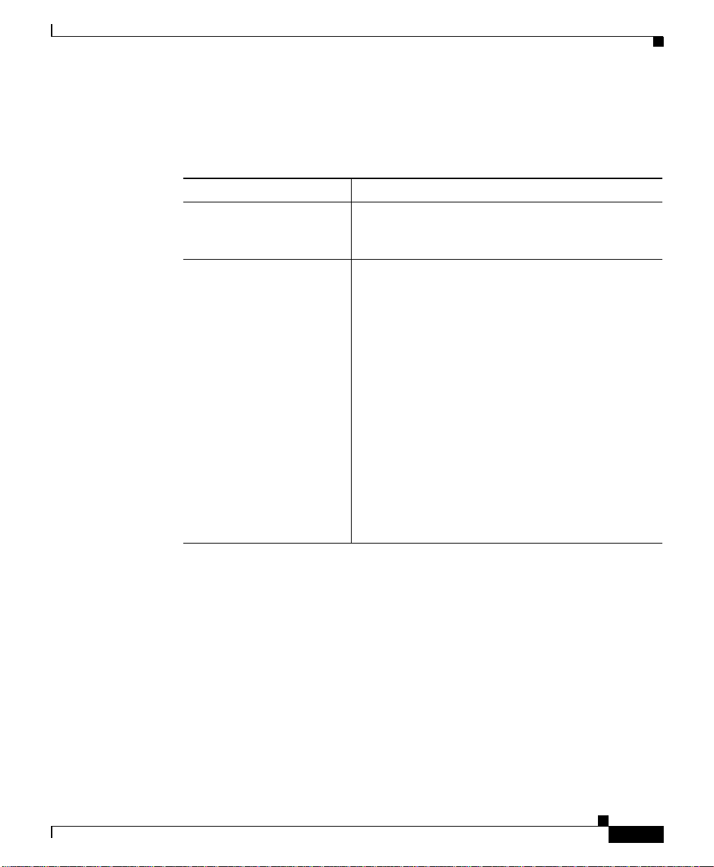
The following table lists the contents of this guide and describes the contents of
each chapter and ap pend ix.
Chapter/Appendix Description
Chapter 1,
Unpacking and
Installing the CSS
Chapter 2, Cabling
the CSS
Appendix A,
Specifications
Appendix B, Cable
Pinouts
Appendix C,
Regulatory
Information
Provides instructions for unp acking and insta lling the
CSS.
Provides instructions for cabling the CSS and the CSS
11800 modules, and describes the CSS L EDs and
connectors. This chapter also provides instructions for
connecting the console, powering the CSS, and
troubleshooting the CSS console, modules, an d power
supply.
Provides specifications for the CSS and components.
Provides pinouts for each connector on the CSS.
Provides information on regulatory com pliance.
xvi
Cisco 11000 Series Content Services Switch Hardware Installation Guide
78-15146-02
Page 17
Preface
Related Documentation
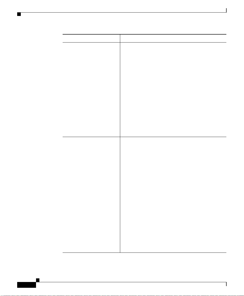
In addition to this docu ment, the CSS doc umen tation set include s th e follow ing :
Document Title Description
Release Note for the Cisco
11000 Series Content
Services Switch
Cisco Content Serv ices
Switch Administration
Guide
Related Documentation
Provides information on operating considera tions,
caveats, and CLI commands fo r the Cisco 11000
series CSS.
Describes how to perform administration tasks on
the CSS including logging into the CSS, upgrading
your CSS software, and configuring the follow ing:
• Management ports, interfaces, and circuits
• DNS, ARP, RIP, IP, and bridging features
• OSPF
• Logging, including displaying log messa ges
and interpreting sys.log messages
78-15146-02
• User profile and CSS pa ram eters
• SNMP
• RMON
• Offline Diagnostic Monitor (Offline DM)
menu
Cisco 11000 Series Content Services Switch Hardware Installation Guide
xvii
Page 18
Related Documentation
Document Title Description
Cisco Content Serv ices
Switch Basic
Configuration Guide
Describes how to perform basic CSS configuration
tasks, including:
• Services
• Owners
• Content ru les
• Sticky parameters
• HTTP header load balancing
• Source groups, Access Control Lists (ACLs),
Extension Qualifier Lists (EQLs), Uniform
Resource Locator Qua lifi er Lists (URQ Ls),
Network Qualifier Lists (NQLs), and Domain
Qualifier Lists (DQLs)
• Caching
Cisco Content Serv ices
Switch Advanced
Configuration Guide
Describes how to p erfo rm adva nced CSS
configuration tasks, including:
• Domain Name Service (DNS)
Preface
xviii
• DNS Sticky
• Content Routing Agent
• Client Side Accelerator
• Network proximity
• VIP and virtual IP interface redundancy
• Box-to-box redundanc y
• Demand-based content replication and content
staging and replication
• Secure Socket Layer (SSL) termination with
the SSL Acceleration Module
• Firewall load balancing
• CSS scripting language
Cisco 11000 Series Content Services Switch Hardware Installation Guide
78-15146-02
Page 19
Preface
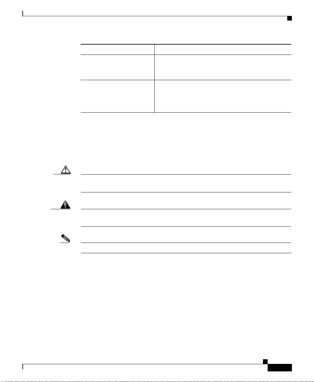
Document Title Description
Cisco Content Serv ices
Switch Command
Reference
Cisco Content Serv ices
Switch Device
Management User’s Guide
Symbols and Conventions
This guide uses the following symbo ls and conve ntions to empha size certai n
information.
Caution A caution means that a specific action you take could cause a loss of data or
adversely impact use of the eq uipment.
Symbols and Conventions
Provides an alphabetical list of all CSS Command
Line Interface commands including syntax,
options, and related command s.
Provides an overview on using the Device
Management user interface, an HTML-based Web
application that you use to configure and manage a
CSS.
78-15146-02
Warning
Note A note provides important related information, reminders, and recommendations.
A warning describes an action that could cause you physical harm or damage
the equipment.
Bold text indicates a command in a paragr aph.
Courier text indicates text that appears in a command line, including the CLI
prompt.
Courier bold text indicates commands and text you enter in a command line.
Italics text indicates the first occurrence of a new term, book title, emphasized text
and variables for which you supply values .
1. A numbered list indicates that the order of the list items is important.
a. An alphabetical list indicates that the order of the secondary list items is
important.
Cisco 11000 Series Content Services Switch Hardware Installation Guide
xix
Page 20

Obtaining Documentation
• A bulleted list indicates that the order of the list topics is unimportant.
–
An indented list indicates that the order of the list subtopics is
unimportant.
Obtaining Documentation
Cisco provides several w ays to ob tain doc umen tation, tec hnical assistance, and
other technical resources. These sections explain how to obtain technical
information from Cisco Systems.
Cisco.com
You can access the most current Cisco documentation on the World Wide Web at
this URL:
http://www.cisco.com/univercd/home/home.htm
You can access the Cisco website at this URL:
Preface
http://www.cisco.com
International Cisco websites can be accessed from this URL:
http://www.cisco.com/public/countries_languages.shtml
Documentation CD-ROM
Cisco documentation and additional literature are available in a Cisco
Documentation CD-ROM pac kage, which may have shippe d with your pro duct.
The Documentation CD-ROM is updated regularly and may be more current than
printed documentation. The CD-ROM package is available as a single unit or
through an annual or q ua rterl y subsc ription .
Registered Cisco.com users can order a single Documentation CD-ROM (product
number DOC-CONDOCCD=) through the Cisco Ordering tool:
http://www.cisco.com/en/US/partner/ordering/ordering_place_order_ordering_t
ool_launch.html
Cisco 11000 Series Content Services Switch Hardware Installation Guide
xx
78-15146-02
Page 21

Preface
All users can order monthly or quarterly subscriptions throug h the online
Subscription Store:
http://www.cisco.com/go/subscription
Ordering Documentation
You can find instructions for ordering documen tation at this URL:
http://www.cisco.com/univercd/cc/td/doc/es_inpck/pdi.htm
You can order Cisco documentation in th ese w ays:
• Registered Cisco.com users (Cisco direct customers) can order Cisco product
documentation from the Ne two rking Pr odu cts Mark etPlace :
http://www.cisco.com/en/US/partner/ordering/index.shtml
• Nonregistered Cisco.c om u ser s c an o rder do cum entation thr ough a loca l
account representative by calling Cisco Systems Corp orate Headq uarter s
(California, U.S.A.) at 408 526-7 208 or, elsewhere in No rth America , by
calling 800 553-NETS (6387).
Obtaining Do cu m e ntation
Documentation Feedback
You can submit comments electronically on Cisco.com. On the Cisco
Documentation home page , click Feedback at the top of the page.
You can e-mail your co mments to b ug- doc@c isco.c om.
You can submit comments by using the response card (if present) behind the front
cover of your document or by writing to the following address:
Cisco Systems
Attn: Customer Document Orde ring
170 West Tasman Drive
San Jose, CA 95134-9883
We appreciate yo ur comm ents .
Cisco 11000 Series Content Services Switch Hardware Installation Guide
78-15146-02
xxi
Page 22

Obtaining Technical Assistance
Obtaining Technical Assistance
Cisco provides Cisco.com, which includes the Cisco Technical Assistance Center
(TAC) website, as a starting point for all technical assistance. Customers and
partners can obtain online doc umenta tion, tro ubles hooting tips , a nd sa mple
configurations from the Cisco TAC website. Cisco.com registered users have
complete access to the technical support resources on the Cisco TAC website,
including TAC tools and utilities.
Cisco.com
Cisco.com offers a suite of interactive, networked services that let you access
Cisco information, networking solutions, services, programs, and resources at any
time, from anywhere in the world.
Cisco.com provides a broad range of features and services to help you with these
tasks:
• Streamline business processes and impro ve productivity
Preface
• Resolve technical issues with online support
• Download and te st so ftwar e pack ages
• Order Cisco learning materia ls a nd me rcha ndise
• Register for online skill assessment, training, and certification programs
T o obtain customized information and service, you can self-register on Cisco.c om
at this URL:
http://tools.cisco.com/RPF/register/register.do
Technical Assistance Center
The Cisco TAC is available to all customers who need technical assistance with
a Cisco product, techn ology, or solution. Two types of support are available: the
Cisco TAC website and the C isco TAC Escalation Center. The type of support
that you choose depends on the p riority of the proble m and the c ond itions stated
in service contracts, when applicable.
Cisco 11000 Series Content Services Switch Hardware Installation Guide
xxii
78-15146-02
Page 23

Preface
We categorize Cisco TAC inquiries according to urgency:
Cisco TAC Website
Obtaining Technical Assistance
• Priority level 4 (P4)—You need information or assistance concerning Cisco
product capabilities, product installation, or basic product configuration .
There is little or no impact to your business operations.
• Priority level 3 (P3)— Oper ation al perf orm ance of the ne twork is im pair ed,
but most business operations remain functional. Y o u and Cisco are willing to
commit resources during normal business hour s to restore service to
satisfactory levels.
• Priority level 2 (P2)—Operation of an existing network is severely degraded,
or significant aspects of your business operations are negatively impacted by
inadequate performance of Cisco products. You and Cisco will commit
full-time resources during normal business hours to resolve the situation.
• Priority level 1 (P1)—An existing network is “down,” or there is a critical
impact to your business operations. You and Cisco will commit all necessary
resources aroun d th e clock to res olve th e situ ati on.
78-15146-02
The Cisco TAC website provides online documents and tools to help troubleshoot
and resolve technical issues with Cisco products and technologies. To access the
Cisco TAC website, go to this URL:
http://www.cisco.com/tac
All customers, partners, and resellers who have a valid Cisco service contract
have complete access to the tec hnical supp ort re source s on the Cisco TAC
website. Some services on the Cisco TAC website require a Cisco.com login ID
and password. If you have a va lid se rv ice c ontr act b ut do n ot have a login ID or
password, go to this URL to register:
http://tools.cisco.com/RPF/register/register.do
If you are a Cisco.c om r eg istere d use r, and you c annot re solve y our tech nica l
issues by using the Cisco TAC website, you can open a case online at this URL:
http://www.cisco.com/tac/caseopen
If you have Internet access, we recommend that you open P3 and P4 cases online
so that you can fully describe the situation and attach any necessary files.
Cisco 11000 Series Content Services Switch Hardware Installation Guide
xxiii
Page 24

Preface
Obtaining Additional Publications and Information
Cisco TAC Escalation Center
The Cisco TAC Escalation Center addresses priority level 1 or priority level 2
issues. These classifications a re assigne d when seve re n etwork de grada tion
significantly impacts business operations . When you contact the TAC Escalation
Center with a P1 or P2 problem, a Cisco TAC engineer automatically opens a
case.
To obtain a directory of toll-free Cisco TAC telephone numbers for your country,
go to this URL:
http://www.cisco.com/warp/public/687/Directory/DirTAC.shtml
Before calling, please check with your network operations center to determine the
Cisco support services to which your company is entitled: for example,
SMARTnet, SMARTnet Onsite, or Network Supported Accounts (NSA). When
you call the center, please have available your service agreement number and your
product serial number.
Obtaining Additional Publications and Information
xxiv
Information about Cisco produ cts, tech nolog ies, a nd ne two rk solution s is
available from vario us online and prin ted sou rces.
• The Cisco Product Catalog describes the networking products offered by
Cisco Systems, as well as ordering and customer support services. Access the
Cisco Product Catalog at this URL:
http://www.cisco.com/en/US/products/products_catalog_links_launch.html
• Cisco Press publishes a wide ran ge of n etworking pu blicatio ns. Cisc o
suggests these titles for new and experienced user s: Internetworking Terms
and Acronyms Dictionary, Internetworking Technology Handbook,
Internetworking Troubleshooting Guide, and the Internetworking Design
Guide. For current Cisco Press titles and other information, go to Cisco Press
online at this URL:
http://www.ciscopress.com
Cisco 11000 Series Content Services Switch Hardware Installation Guide
78-15146-02
Page 25

Preface
Obtaining Additiona l Publications and Information
• Packet magazine is the Cisco quarterly publication that provides the latest
networking trends, techn ology bre akthrou ghs, a nd Cisc o produc ts and
solutions to help industry professionals get the most from their networking
investment. Included are n etwor king deploy ment a nd tro uble shoo ting tip s,
configuration ex am pl es , cu sto me r ca s e s tud i es, tu to ri als an d tr ai n ing ,
certification information, and links to numero us in-depth onlin e resources.
You can access Packet magazine at this URL:
http://www.cisco.com/go/packet
• iQ Magazine is the Cisco bimonthly publication that delivers the latest
information about Internet business strategies for executives. Y ou can access
iQ Magazine at this URL:
http://www.cisco.com/go/iqmagazine
• Internet Protocol Journal is a quarterly journal published by Cisco Systems
for engineering p rofe ssiona ls inv olved in de signin g, de ve loping, an d
operating public and private internets and intranets. You can access the
Internet Protocol Journal at this URL:
http://www.cisco.com/en/US/about/ac123/ac147/about_cisco_the_internet_
protocol_journal.html
78-15146-02
• Training—Cisco offers world-class networking training. Current offerings in
network training are listed at this URL:
http://www.cisco.com/en/US/learning/le31/learning_recommended_training
_list.html
Cisco 11000 Series Content Services Switch Hardware Installation Guide
xxv
Page 26

Obtaining Additional Publications and Information
Preface
xxvi
Cisco 11000 Series Content Services Switch Hardware Installation Guide
78-15146-02
Page 27
CHAPTER
1
Unpacking and Installing the CSS
This chapter describes how to unpack and install the CSS 11050, CSS 11 150, and
CSS 11800 as free-standing or rack-mo unt units.
This chapter contains the following major sections:
• Site Requirements
• Shipment Contents
• Unpacking the CSS
• If the Product is D ama ged
• Installing the CSS 11050 or CSS 11150
• Installing the CSS 11800
• Installing a CSS 11800 Module
78-15146-02
Note For information on installing a replacement or accessory item in the CSS 11800
(such as a redund ant AC o r DC po wer sup ply, or fan unit) consu lt the refe r ence
sheet included with the item.
Cisco 11000 Series Content Services Switch Hardware Installation Guide
1-1
Page 28

Site Requirements
Site Requirements
Before you select an installation site for the CSS, read the electrical,
environmental, and physical re quirement s as described in Ap pendix A,
Specifications. If you are installing a DC unit (CSS 11150 or CSS 11800 only),
ensure that you r ead an d follow the DC po wer su pply saf e ty wa rning s in
Appendix A, Specifications.
Required Tools and Equipment
To install the CSS hardware, you need the following tools and equipment:
• A Phillips and a flat-head screwdriver
• Anti-static wrist strap (included in the CSS 11800 accessory kit)
• Hand lift (recommended) for lift ing the CSS 11800 chassis into the
equipment rack
Once you complete the installation, you need a console terminal (or equivalent)
that runs at 9600 bp s to issue c on sole comm an ds.
Chapter 1 Unpacking and Installing the CSS
Shipment Contents
The CSS 11050, CSS 11150, and CSS 11800 shipment contains the following
items except where noted:
• Content Services Switch
• Anti-static wrist strap (CSS 11800 only)
• Four rubber feet ( CSS 11050 and CSS 11150)
• Mounting brackets and hardware (CSS 11050 and CSS 11150)
Cisco 11000 Series Content Services Switch Hardware Installation Guide
1-2
78-15146-02
Page 29

Chapter 1 Unpacking and Installi ng the CSS
• Console cable kit:
–
RS-232 shielded mode m c able
–
RJ-45 to female 25-p in su b-d conn ector
–
RJ-45 to female 9-pin sub -d c onnec tor
–
RJ-45 to RJ-45 Cisco console adapter cable
• Standard software license key. If you ordered the Enhanced featur e set, the
Secure Management option (which include the Secure Shell Host option and
SSL strong encryption for the Device Managem ent software), or the
Proximity Database feature, additional Claim Certific ates will be included in
the Accessory kit.
Note If you cannot locate the Standard software license key or a license key
Claim Certificate in the Accessory kit, call the Cisco Technical
Assistance Center (TAC) toll free, 24 hours a day, 7 days a week at
1-800-553-2447 or 1- 408 -52 6-7209 . You can also e-mail TAC at
tac@cisco.com.
Unpacking the CSS
• Cisco 11000 Series Content Services Switch Hardware Installation Guide
Unpacking the CSS
The CSS is shipped in a protective shipping carton. T he CSS 11050 and
CSS 11150 are shipped as a se lf-con taine d ch ass is; no mo dule s o r com pon ents
can be added or r em oved. The C SS 11800 is shipped with the pow er sup ply, fan
unit, SCM, and SFM preinstalled. You must install all separately ordered items
(for example, I/O modules or a redu ndant AC or DC pow er supply) in to the
CSS 11800.
This section describes:
• Unpacking the CSS 11050 or CSS 11150
• Unpacking the CSS 11800
Cisco 11000 Series Content Services Switch Hardware Installation Guide
78-15146-02
1-3
Page 30

Unpacking the CSS
Unpacking the CS S 110 50 or CS S 11 15 0
To unpack the CSS 11050 or CSS 11150:
1. Remove the CSS and all accessories from the shipping carton.
2. Check the configuration of the CSS and the accessories against the items
listed on the packing slip. Report any discrepancies as describe d in “If the
Product is Damaged” in this chapter.
3. To install the CSS 11050 or CSS 11150, go to the “Installing the CSS 11050
or CSS 11150” section.
Unpacking the CSS 11800
The CSS 11800 is ship pe d att ach ed to a w oo den pa ll et wi th s cre w s an d s hip p ing
brackets. Due to the large size and weight of a unit, move it to t he installation site
before unpacking it from the shipp ing carton.
To unpack the CSS 11800:
Chapter 1 Unpacking and Installing the CSS
1-4
1. Remove all enclosed packing materials. Save the packing materials in case
you need to repack the CSS later.
2. Remove the accessories from the shipping carton.
3. Check the configuration of the CSS and the accessories against the packing
slip. Report any discrepancies as described in the “If the Product is Damaged”
section later in this chapter.
4. Using a Phillips screwdriv er, remove the scre ws from the sh ipping br acke ts
on the pallet. Figure 1-1 shows the CSS 11800 attached to the wooden pallet.
5. Carefully remove the CSS from the pallet.
Cisco 11000 Series Content Services Switch Hardware Installation Guide
78-15146-02
Page 31

Chapter 1 Unpacking and Installi ng the CSS
Figure 1-1 CSS 11800 Shipping Pallet
Shipping
brackets
If the Product is Damaged
Shipping
brackets
49566
6. To install the CSS, go to the “Installing the CSS 11800” section.
If the Product is Damaged
If any portion of the un it or comp one nt is dama ged in tr an sit, f orwa rd a n
immediate request to the delivering carrier to perform an inspection of the product
and to prepare a damage report. Save the container and all packing materials until
the contents are verified.
Cisco 11000 Series Content Services Switch Hardware Installation Guide
78-15146-02
1-5
Page 32

Chapter 1 Unpacking and Installing the CSS
Installing the CSS 11050 or CSS 11150
Concurrently, report the nature and extent of the damage to Custom er Service.
Report the problem or deficiency to Customer Service along with the model
number and serial number. Upon receipt of this information, you will be provided
with service instructions, or a Return Materia l Authorization (RMA) Number a nd
shipping information.
Installing the CSS 11050 or CSS 11150
The CSS 11050 or CSS 11150 can be placed on a flat surface as a free-s tanding
unit or rack-moun ted in an equipment cab inet. The following secti ons describe the
steps to ins tall the C SS as a:
• Free-standing unit
• Rack-mounted unit
Prior to installing the CSS, observe the following installation requirements:
• The ambient operating te mper atur e is 3 2° to 104° F (0 to 40° C).
If you install the CSS in a closed or multi-unit rack, the operating ambient
temperature of the rack environment may be greater than the room ambient
temperature. Ensure that the temperatu r e do es no t exceed the CSS m axi mum
ambient operating temperature.
• The minimum cleara nce re quirem ent is 2 in ches (10 cm) of a ir fl ow spac e on
both sides of the chassis.
1-6
• Ensure that the CSS is reliably grounded to earth. W e recommend that you do
not use power strips or extension cords to connect the CSS to the po wer
source.
Caution Do not remove the CSS 11050 or CSS 11150 cover. There are electrical shock
hazards presen t in th e unit if the co ver is remove d. Ther e are no serv iceab le or
installable components availa ble w ith the C SS 11050 and CSS 11150.
Do not use a 3-prong to 2-prong electrical adapter. This will compromise the
grounding.
Note Removing the CSS 11050 or CSS 11150 cover voids its warranty.
Cisco 11000 Series Content Services Switch Hardware Installation Guide
78-15146-02
Page 33

Chapter 1 Unpacking and Installi ng the CSS
Installing the CSS 11050 or CSS 11150
Installing the CSS 11050 or CSS 11150 as a Free-Standing Unit
Position the CSS 11050 or CSS 11150 on the selected flat surface. When
installing the CSS, note that all cables connect to the front of the unit with the
exception of the cable that connects to the Ethernet management port on the rear
panel and the power c ord.
Rack-Mounting the CSS 11050 or CSS 11150
Before you rack-mount th e CSS 11050 or CSS 11150:
• Determine if you want to front-mount or mid-mount the CSS chassis into the
cabinet. The difference b etwee n front- mou nt o r mid-m ou nt is:
–
Front-mount sets the front edge of the unit even with the front edge of the
rack
–
Mid-mounting the CSS sets the front edge of the unit past the front edge
of the rack
• Install the mounting brackets on the CSS. The rack position of the CSS
determines where you will install the mounting brackets on the CSS chassis.
See the following section to install the mounting brackets.
Installing the Mounting Brackets
Before you begin, you will need the mounting brackets and eight screws shipped
in the accessory kit ac company ing the CSS 11050 and CSS 11150, and a #2
Phillips screwdriver.
To install the mounting brackets on the CSS chassis:
1. Position the CSS with its front panel facing you. On the left and right side of
its chassis, note the screw holes for installing the mounting brackets.
2. Position a bracket on one side of the chassis. Align the bracket with the
appropriate screw holes for front- or mid- mounting.
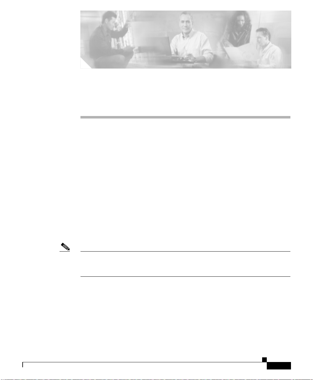
Figure 1-2 illustrates front-mounting the brackets. Figure 1-3 illustrates
mid-mounting the brackets.
Cisco 11000 Series Content Services Switch Hardware Installation Guide
78-15146-02
1-7
Page 34
Installing the CSS 11050 or CSS 11150
Figure 1-2 Front-Mounting the Brackets on the CSS 11050 or CSS 11150
Chapter 1 Unpacking and Installing the CSS
Mounting
bracket
Mounting
bracket
49567
Figure 1-3 Mid-Mounting the Brackets on the CSS 11050 and CSS 11150
Mounting
bracket
Mounting
bracket
49568
3. Secure the bracket to the CSS with four screws.
4. Repeat steps 2 and 3 to install a mounting bracket on the other side of the
CSS.
You are ready to install the CSS in the cabinet.
Installing the CSS into the Rack
Before you begin, you will need a #2 Phillips screwdriver and fou r pan-head
screws. To install the CSS 11050 or CSS 11150 into an equipment rack:
1. Raise the CSS to the installation height. Align the screw holes on the
mounting bracket with th e hole s o n th e equipm en t ra ck.
Cisco 11000 Series Content Services Switch Hardware Installation Guide
1-8
78-15146-02
Page 35

Chapter 1 Unpacking and Installi ng the CSS
2. Use a #2 Phillips screwdriver and two pan-head sc rew s to se cure each
mounting bracket to each side of the rack.
Installing the CSS 11800
The CSS 11800 is a rack-moun t unit. Whe n positio ning the C SS 11800 for
installation, keep in mind that all cables connect to the front of the unit.
Prior to rack-mounting the CSS, observe the following installation requirements:
• The maximum ambient operatin g temperatur e for the CSS 11800 is 32° to
104° F (0 to 40° C). When you install the CSS 1 1800 in a closed or multi-unit
rack, the operating ambient temperature of the rack environment may be
greater than the room ambient temperature. Ensure that the temperature does
not exceed the CSS maximum ambien t operating tempe rature.
• Ensure that the CSS 11800 is reliably grounded to earth. Do not use pow er
strips or extension cords to connect the CSS to the power source .
Before you rack-mount the CSS 11800 chassis, determine if you want to
front-mount, mid-mount, or exten d-mou nt the c hassis in the ca binet:
Installing the CSS 11800
• Front-mount the chassis to set the front edge of the unit even with the front
edge of the rack . The brackets are pre installed in this position on the chassis
and are ready for m ounting in a r ack, as de scribe d in the “Rack-Mounting the
CSS 11800 Chassis” section.
• Mid-mount the chassis to set the fr ont ed ge of the unit in fr ont of the fron t
edge of the rack. To mid-mount the brackets on th e cha ssis, follow the step s
in “Mid-Mounting the CSS 11800 Brackets”.
• Extend-mount the chassis to set the front edge of the unit behind the front
edge of the rack; allowing the chassis to be installed in an enclosed rack. To
extend-mount the brackets on the chassis, follow the steps in
“Extend-Mounting the CSS 11800 Bracke ts” .
Mid-Mounting th e CSS 118 00 Br ac ke ts
To change the location of the mounting brackets on the CSS 11800 chassis from
a front-mount position to a mi d-m ount po sition (s ee Figure 1-4):
1. Remove the seven front mounting bracket screws from one side of the chassis.
Cisco 11000 Series Content Services Switch Hardware Installation Guide
78-15146-02
1-9
Page 36

Chapter 1 Unpacking and Installing the CSS
Installing the CS S 11800
2. Position the mounting bracket onto the middle of one side of the CSS, lining
up the front screw holes on the bracket with the hole s on the side of the
chassis.
Figure 1-4 Aligning Brackets on the CSS 11800 for Mid-Mounting
Mounting
bracket
Mounting
bracket
Mounting
key
Mounting
key
1-10
49569
3. Using a Phillips screwdriv er, install only five of the s even #1 0-3 2 p an-hea d
screws through the mid-mount bracket holes into the CSS. Do not install the
screws in the top of the bracket or second from the bottom of the bracket.
4. Repeat steps 1 through 3 to in stall the secon d b racket onto the oth er side of
the chassis.
When the brackets are in position for mounting the chassis in a rack, proceed to
the “Rack-Mounting the CSS 11800 Chassis” section.
Cisco 11000 Series Content Services Switch Hardware Installation Guide
78-15146-02
Page 37
Chapter 1 Unpacking and Installi ng the CSS
Extend-Mounting the CSS 11800 Brackets
Y ou can extend-mount a CSS 11800 chassis to set the front edge of the unit behind
the front edge of the rack to allow the chassis to be installed in an enclosed rack.
Before you can exte nd-mo unt a ch assis, y ou need to repos ition its m ountin g
brackets. Each b rack et ha s two s ets of scre w holes. T he set of ho les you u se to
install the brackets to the chassis determines how the chassis is mounte d in a rack:
• The screw holes toward the front of the bracket position each bracket on the
CSS 11800 chassis for front mounting in a cabinet; this is the preinstalled
position.
• The screw holes behind the firs t set of holes position each br acket on the
CSS 11800 chassis for extende d mounting in a cabinet.
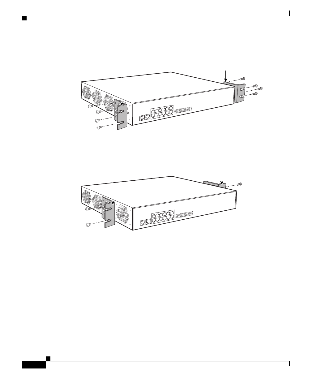
Figure 1-5 illustrates extend-mounting the brackets.
Figure 1-5 Screw Holes on the CSS 11800 Bracket for Front and Extended
Mounting
Front Front
Installing the CSS 11800
78-15146-02
Screw holes for
the front-mounting
of the 11800 chassis
in a cabinet
Cisco 11000 Series Content Services Switch Hardware Installation Guide
Screw holes for the
extended-mounting
of the 11800 chassis
in a cabinet
49570
Left bracket Left bracket
1-11
Page 38

Chapter 1 Unpacking and Installing the CSS
Installing the CS S 11800
To change the location of the mounting brackets on the CSS 11800 chassis from
a front-mount position to an extended-mount position:
1. Remove the seven front mounting bracket screws from one side of the chassis.
2. Align the rear screw holes on the bracket with the screw holes on the front
side of the chassis. Note the brac ket’s proper orientation as show n in
Figure 1-6.
Figure 1-6 Aligning Brackets on the CSS 11800 Chassis for Extended Mounting
Mounting
bracket
Mounting
bracket
Mounting
key
1-12
Mounting
key
49571
3. Using a Phillips screwdriver, install the seven #10-32 pan-head screws
through the extended-mo unt bra cket holes in to the CSS.
4. Repeat steps 1 through 3 to in stall the secon d b racket onto the oth er side of
the chassis.
Cisco 11000 Series Content Services Switch Hardware Installation Guide
78-15146-02
Page 39

Chapter 1 Unpacking and Installi ng the CSS
When the brackets are in position for mounting the chassis in a rack, proceed to
the “Rack-Mounting the CSS 11800 Chassis” section.
Rack-Mounting the CSS 11800 Chassis
Once the mounting brackets are installed, you are ready to install the CSS 11800
chassis.
Installing the CSS 11800
Warning
The weight and position of the CSS 11800 chassis within the cabinet may make
the cabinet top-heavy or unstable. T ake all necessary precautions to anch or the
cabinet securely before installing the chassis.
To install the CSS 11800 chassis into a cabinet:
1. Locate the moun ting k ey s on the left an d ri ght mounting bra cke ts ( see
Figure 1-4). Mounting keys are designed to fit over pan-head screws installed
in the mounting rack to ho ld th e chassi s in pl ace wh ile yo u secur e the chassis
into the rack.
2. Install a pan-head screw into the left and right sides of the mounting rack.
These screws fit into the mounting keys and hold the chassis.
3. Raise the CSS to the appropriate installation height and place the mounting
keys over the installed pan-head screws. The CSS is now held in place by the
mounting keys so you can install the remaining screws.
4. Align the screw holes on the mounting bracket with the screw holes on the
equipment cabinet and install the pan-head screws th rough the CSS and
cabinet brackets. The CSS 11800 requires five pan-head screws for each side
of the chassis.
78-15146-02
Cisco 11000 Series Content Services Switch Hardware Installation Guide
1-13
Page 40

Installing a CSS 11800 Module
Installing a CSS 11800 Module
This section applies to the CSS 11800 modules only and contains the following
sections:
• Installation Precautions and Restrictions
• Unpacking a CSS 11800 Module
• Installing a Module
• Installing a Passive SCM or SFM
Installation Precautions and Restrictions
This section includes background material related to installing a module into the
CSS 11800 chassis. It is recommended that you read the topics in this section
before installing a module.
Installation Precautions
Chapter 1 Unpacking and Installing the CSS
1-14
Read and observe the following precautionary information prior to servicing the
CSS 11800.
Warning
Warning
Cisco 11000 Series Content Services Switch Hardware Installation Guide
Do not remove or install modules without using appropriate anti-static guard
measures. The CSS includes an anti-static wrist strap in the accessory kit.
Attach the copper tape end of the strap to an unpainted metal surface on the
chassis. You can leave the strap connected to the chassis when you are done.
If you do not power down the CSS 11800, an electrical energy hazard is present
within the chassis. Prior to installing or removing components, remove all
metallic objects from hands and wrists to prevent bridging of live contact
points.
78-15146-02
Page 41

Chapter 1 Unpacking and Installi ng the CSS
Module Slot Restrictions
Modules are restricted to specific slots due to bandwidth capabilities. The CSS
11800 chassis backplane is designed for sp ecific modu les to r eside in their
respective slots. For example, you cannot install a SCM in slot 2 beca use the
backplane connector for slot 2 does not accommodate a SCM connector. Prior to
installing a module, see Table 1-1 for infor mation on chas sis slot usage.
Table 1-1 Chassis Slot Usage
Slot Number Slot Usage Slot Color Code
1 I/O Module Blue
2 I/O Module Blue
3 I/O Module Blue
4 I/O Module Blue
5 SFM or SFM2 (passive module) Purple
6 SFM or SFM2 (active module) Purple
7 SCM (initial active module) Red
8 SCM (initial passive module) Red
9 SFM or SFM2 (active module) Purple
10 SFM or SFM2 (passive module) Purple
11 I/O Module Blue
12 I/O Module Blue
13 I/O Module Blue
14 I/O Module Blue
15 Internal Disk Module (flash or hard disk) Green
Installing a CSS 11800 Module
78-15146-02
Cisco 11000 Series Content Services Switch Hardware Installation Guide
1-15
Page 42

Installing a CSS 11800 Module
Figure 1-7 illustrates a fully configured CSS 11800.
Figure 1-7 Fully Configured CSS 11800
Slot 1 Slot 15
Chapter 1 Unpacking and Installing the CSS
1-16
49572
Cisco 11000 Series Content Services Switch Hardware Installation Guide
78-15146-02
Page 43

Chapter 1 Unpacking and Installi ng the CSS
Removing or Installing a Module
You must power down the CSS 11800 chassis to remove or install a module. If
you install a new module while the CSS is operational, the SCM will not
recognize the module until the next reboot.
Installing a CSS 11800 Module
Warning
If you replace an active SCM with a new SCM, the boot configuration reverts
back to its default settings. You must reconfigure these parame ters through the
Offline Diagnostic Monitor menu. For more information on accessing and using
this menu, refer to the
Content Services Switch Administration Guide
When you remove a module and replace it with a module of the same type, the
SCM automatically downloads the boot image and configuration files for the
module. (For information on image and configuration files, refer to the Content
Services Switch Administration Guide.) The newly installed module boots up
with:
• The appropriat e module imag e
• The same configuration as the former module
When you remove a module and replace it with a module of a different type, the
SCM downloads the module boot image automatically. The newly installed
module boots up with the appropriate module im age.
Unpacking a CSS 1180 0 Mod ule
To unpack a CSS 11800 module:
1. Verify that the module is the model you ordered by checkin g the model
number listed on the side of the shipping carton
2. Remove the module, in its anti-static bag, from the shipping carton.
.
78-15146-02
3. Put on the anti-static strap provided with your CSS.
4. Remove the module from the anti-static shielding bag and inspect it for
damage.
Always hold the module by the faceplate, being care ful not to touch the
components. If the module appears to be damaged, return it to the anti-static
bag, repack it in the shipping ca rton, a nd c ontac t you r local su pplier.
Cisco 11000 Series Content Services Switch Hardware Installation Guide
1-17
Page 44

Installing a CSS 11800 Module
5. For the procedure on installing a module into the CSS 11800 chassis, see the
“Installing a Module” section.
Installing a Module
You must power down the CSS 11800 chassis to install a module.
Note For the procedure on installing a passive SCM or SFM, see the “Installing a
Passive SCM or SFM” section. For information on removing and repla cing a
module, see the “Removing or Installing a Module” section.
To install a module:
1. Properly ground yourself prior to handling the module. For example, wear the
anti-static wrist strap (included in the accessory kit) and stick the copper-tape
end of the strap to an unpainted metal surface on the chassis. Make sure that
the wrist strap makes good contact with your skin.
2. Locate an ope n slot i n the ch ass is for th e modul e. See Table 1-1 to identify
possible slots for the module. If necessar y, remove a blank panel from the
chassis to exp ose a slo t for th e modul e.
Chapter 1 Unpacking and Installing the CSS
1-18
Cisco 11000 Series Content Services Switch Hardware Installation Guide
78-15146-02
Page 45
Chapter 1 Unpacking and Installi ng the CSS
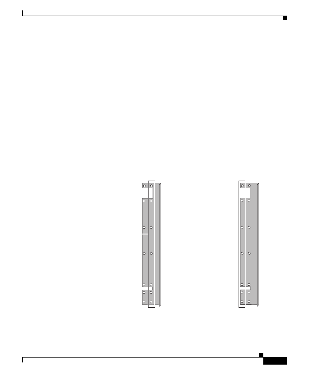
3. Insert the module into the board guides a t the top and bottom of the slot an d
slide it into the chassis by pressing firmly at the top and bottom of the
faceplate as sho w n in Figur e 1-8.
Figure 1-8 Installing a Module into a CSS 11800 Chassis
Installing a CSS 11800 Module
78-15146-02
49573
4. Close both ejectors simultaneously to seat the module connector into the
backplane.
5. Using a Phillips screwdriver, tighten the spring-loaded screws on the front of
the module faceplate. Once you install the module, it begins diagnostics and
initializes automatically.
If you installed a SFM or SFM2, you must reboot the chassis to activate it.
6. If you are installing additional GBICs in a Gigabit Ethernet module, position
the GBIC with its receive connector above its transmit connector.
Cisco 11000 Series Content Services Switch Hardware Installation Guide
1-19
Page 46

Installing a CSS 11800 Module
Installing a Passive SCM or SFM
You can install a passive SCM or SFMs (which includes SFM2s) in a CSS 11800
chassis. Passive modules are stand-by modules in case of an active module failure.
When an active module fails, the passive module becomes active. Passive modules
do not load share pr ocessin g f unctions with the a ctive mo dule.
Note The SCM contains a small lithium battery. Some jurisdictions restric t the ways in
which items containing lithium batteries may be disposed. In particular, lithium
batteries or products containing lithium batteries may never be disposed of in an
unregulated fire. Other restrictions might apply. See Appendix A, Specifications
for lithium battery disposal warnings.
Chapter 1 Unpacking and Installing the CSS
Warning
Ultimate disposal of a lithium battery should be handled according to all
national laws and regulations.
The CSS 11800 enables you to install a passive:
• SCM for the active SCM
• SFM for each of the two active SFMs (total of four SFMs)
Note You can mix SFMs with SFM2s in the same CSS 11800 chassis. H owever, you
must use the same type module as the active SFM and as the passive SFM.
To install a passive SCM or SFM:
1. Properly ground yo urse lf prio r to ha ndlin g the mod ule.
2. If the CSS is powered up, power it down.
3. As defined in Table 1-1:
• SCMs are restricted to slots 7 or 8
• Passive SFMs are restricted to slots 5 and 10 (by default, active SFMs are
in slots 6 and 9, respectively)
4. If necessary, remove a blank panel from the chassis to expose a slot.
1-20
Cisco 11000 Series Content Services Switch Hardware Installation Guide
78-15146-02
Page 47

Chapter 1 Unpacking and Installi ng the CSS
5. Insert the module into the board guides a t the top and bottom of the slot an d
slide it into the chassis by pressing firmly at the top and bottom of the
faceplate.
6. Close both ejectors simultaneously to seat the module connector into the
backplane.
7. Using a Phillips screwdriver, tighten the spring-loaded screws on the front of
the module faceplate.
• A SCM module begins diagnostics and initializes automatically.
• To power on the SFM or SFM2, reboot the CSS.
8. Power up the CSS.
9. To copy the boot configuration from the active SCM to the passive SCM, use
the passive sync command in boot configura tion mode.
Passive Module Switchover
If the active SCM fails:
1. The CSS reboots and connection s are terminated.
Installing a CSS 11800 Module
78-15146-02
2. The CSS restores all configurations using the startup-config file.
3. The passive SCM becomes active automatically.
If an active SFM or SFM2 fails:
1. The CSS performs a cold boot and connections are terminated.
2. The CSS restores all configurations using the startup-config file.
3. A passive SFM becomes active automatically.
Note When the CSS 11800 chassis contains two passive SFMs or SFM2s and an active
switchover occurs, both passive SFMs or SFM2s switch over to becom e a ctive
SFMs.
Cisco 11000 Series Content Services Switch Hardware Installation Guide
1-21
Page 48

Installing a CSS 11800 Module
Chapter 1 Unpacking and Installing the CSS
1-22
Cisco 11000 Series Content Services Switch Hardware Installation Guide
78-15146-02
Page 49

CHAPTER
2
Cabling the CSS
This chapter describes the individual CSS interfaces, how to cable the CSS and its
interfaces, how to attach a c onso le fo r co nsole manag em ent, an d how to conne ct
the AC or DC power cord. This chapter also describes the CSS LEDs and
connectors. The information in this chapter applies to the CSS 11050, CSS 11 150,
and CSS 11800 except where noted.
This chapter contains the following major sections:
• Cabling the CSS 11050 and CSS 11150
• Cabling the CSS 11800 Modules
• Connecting Power Cords
• Connecting the Console to the CSS
• Powering Up the CSS
• Powering Down the CSS
• Troubleshooting CSS Hardware Components
Cabling the CSS 11050 and CSS 11150
The CSS 11050 and CSS 11150 are fixed configuration devices designed for small
Web sites or remote satellite Web sites. Each of these devices provide 5 Gbps of
switch bandwidth and integrated LAN ports. They feature all of the networking
software capabilities necessary for connecting remote Web sites to the Internet or
the home Web site.
Cisco 11000 Series Content Services Switch Hardware Installation Guide
78-15146-02
2-1
Page 50

Cabling the CSS 11050 and CSS 11150
Figure 2-1 illustrates a CSS 11151 with 12 auto-sensing 10/100-Mbps Etherne t
(10BASE-T/100BAS E-T X) inte rf ace s.
Figure 2-1 CSS 11151 Content Services Switch
The CSS 11050 configuration supports:
• Eight auto-sensing 10/10 0-Mbp s E the rnet (10B ASE -T/ 100 BASE- TX)
interfaces
• Optional integrated Gigabit Ethernet Network Interface Card (GENIC) with
one uplink port
Chapter2 Cabling the CSS
49574
2-2
The CSS 11150 configuration supports:
• 12 auto-sensing 10/100-M bp s Eth erne t (1 0BAS E-T /100B ASE -TX )
interfaces
• Optional integrated Gigabit Ethernet Network Interface Card (GENIC) with
two GBIC ports, in either 4 MB or 8 MB per port versions
• Optional integrated Fast Ethernet Network Interface Card (FENIC) wit h four
SC connectors for uplinks
• Optional integrated Fast Ethernet Network Interface Card (FENIC) wit h four
additional auto-sensing 10/10 0-M bp s Et herne t ( 10B ASE-T /100 BA SE-TX )
interfaces for a total of 16 interfaces
Cisco 11000 Series Content Services Switch Hardware Installation Guide
78-15146-02
Page 51

Chapter 2 Cabling the CSS
Cabling the CSS 11050 and CSS 11150
CSS 11050 and CSS 11150 Rear Panel Connectors and LEDs
The CSS 11050 and CSS 11150 have connectors and LEDs on their front and rear
panels. The rear panel has an AC connec tor (or DC conne ctor on a CSS 11150),
an Ethernet management RJ-45 connector, and the associated Ethernet
Link/Activity, 10/100 (Mbps) , and Duplex (Half or Full) LE Ds, as shown in
Figure 2-2.
Figure 2-2 CSS 11050 and CSS 11150 Rear Panel Connectors and LEDs
AC connector
Power switch
Ethernet management port
Management
10/100 Ethernet
Link/Act
Duplex
10/100
Table 2-1 desc ribes the LED s on the r ear pa nel.
Table 2-1 CSS 11050 and CSS 11150 Ethernet Management Port LED
Descriptions
LED Name Color State Indicates
Link/Act Green Off No link establishe d
On Link established
Blinking Link established and activity
Duplex Green Off Half duplex
On Full duplex
10/100 Green Off Port is operating at 10 Mbps
On Port is operating at 100 Mbps
49575
78-15146-02
Cisco 11000 Series Content Services Switch Hardware Installation Guide
2-3
Page 52

Cabling the CSS 11050 and CSS 11150
CSS 11050 Front Panel Connectors and LEDs
All front panels of the CSS 11050 models contain connectors and LEDs that vary
according to their model numbe r. For example, the CSS 11051 in Figure 2-3 has:
• One RS-232 Console con nec tor ( 9600 b aud)
• One RS-232 Diag conn ec tor, reserved f or fie ld se rv ice u se only
(115,200 baud)
• Eight auto-sensing 10/100-Mbps Fast Ethernet connectors and associated
Link/Activity status, 10/100 (M bp s), a nd D uplex (Ha lf o r Full) L EDs
• Power, Status, and Ready LEDs
Figure 2-3 CSS 11051 Front Panel Connectors and LEDs
Chapter2 Cabling the CSS
100BASE-TX
1 2 3 4 5 6 7 8
Link/Act
Duplex
10/100
Console
RS-232
2X 4X 6X 8X
Diag
1X 3X 5X 7X
The CSS 11052 (shown in Figur e 2-4) also has o ne G igabit E the rnet c on nection
using a Gigabit Interface Converter (GBIC), and associated Transmit, Receive,
and Link LEDs. Th e GBIC c ompli es with Rev ision 5.1 of the GB IC spec ifi cation
for Class 4 GBICs. The GBIC network interface complies with the IEEE
1000BASE-SX specification fo r shor t las er wa vele ngth of 8 50 nm and use
SC-type fiber conn ecto rs.
Figure 2-4 CSS 11052 Front Panel Connectors and LEDs
Gigabit Ethernet port (left - receive, right - transmit) and LEDs
100BASE-TX
1 2 3 4 5 6 7 8
Link/Act
Duplex
10/100
Console
RS-232
2X 4X 6X 8X
Diag
1X 3X 5X 7X
Power
Status
Ready
Power
Status
Ready
1000BASE-SX
Link/Sync
Rx
Tx
49576
49577
2-4
Cisco 11000 Series Content Services Switch Hardware Installation Guide
78-15146-02
Page 53

Chapter 2 Cabling the CSS
Table 2-2 CSS 11050 Front Panel LED Descriptions
Cabling the CSS 11050 and CSS 11150
LED Name Color State Indicates
Link/Act
(Fast Ethernet ports)
Green Off No link established
On Link established
Blinking Link established and activity
Duplex
(Fast Ethernet ports)
10/100
(Fast Ethernet ports)
Green Off Half duplex
On Full duplex
Green Off Port is operating at 10 Mbps
On Port is operating at 100 Mbps
Power Green Off CSS does no t have power
On CSS has power
Status Yellow Off CSS is operational
Blinking C SS detects an error dur ing
offline or online testing, or the
boot diagnostic failed and the
system cannot boo t
Ready Green Off CSS is booting
On CSS is operational
Blinking CSS is accessing the disk
Tx (Transmit)
(Gigabit port on the
CSS 11052)
Rx (Receive)
(Gigabit port on the
CSS 11052)
Link/Sync
(Gigabit port on the
CSS 11052)
Green Off No transmit packet activity
Blinking Transmit activity detected
Green O ff No recei ve pa cket activ ity
Blinking Receive activity detected
Green Off No link
On Link exists and synch ronizat ion
achieved
Blinking Link exists but not synch ronized
78-15146-02
Cisco 11000 Series Content Services Switch Hardware Installation Guide
2-5
Page 54

Cabling the CSS 11050 and CSS 11150
CSS 11150 Front Panel Connectors and LEDs
All front panels of the CSS 11150 models front panels contain connec tors and
LEDs that vary according to their model number. For example, the CSS 11151
front panel in Figure 2-5 has:
• One RS-232 Console con nec tor ( 9600 b aud)
• One RS-232 Diag conn ec tor, reserved f or fie ld se rv ice u se only
(115,200 baud)
• 12 auto-sensing 10/100-M bp s Fast E ther net conn ector s a nd as sociat ed
Link/Activity status, 10/100 (M bp s), a nd D uplex (Ha lf o r Full) L EDs
• Power, Status, and Ready LEDs
Figure 2-5 CSS 11151 Front Panel Connectors and LEDs
Chapter2 Cabling the CSS
100BASE-TX
1 2 3 4 5 6 7 8 910 1112
Link/Act
Duplex
10/100
Console
RS-232
2X 4X 6X 8X 10X 12X
Diag
1X 3X 5X 7X 9X 11X
The CSS 11152 (shown in Figure 2-6) has fo ur a dditional Fa st Et herne t TX
connectors and their associated Link/Activity status, 10/100 (Mbps), and Duplex
(Half or Full) LEDs.
Figure 2-6 CSS 11152 Front Panel Connectors and LEDs
Additional Fast Ethernet TX connectors and LEDs
100BASE-TX
1 2 3 4 5 6 7 8 910 1112
Link/Act
Duplex
10/100
Console
RS-232
2X 4X 6X 8X 10X 12X
Diag
1X 3X 5X 7X 9X 11X
Cisco 11000 Series Content Services Switch Hardware Installation Guide
2-6
Power
Status
Ready
13X 14X 15X 16X
Power
Status
Ready
1000BASE-TX
13141516
49578
Link/Act
Duplex
10/100
49579
78-15146-02
Page 55
Chapter 2 Cabling the CSS
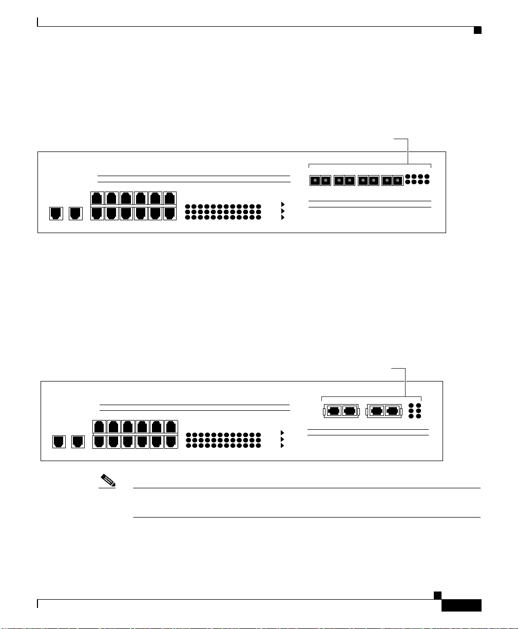
The CSS 11153 (shown in Figure 2-7) has fo ur a dditional Fa st Et herne t
100BASE-FX SC fiber connec tors and their assoc iated Link a nd Activity LEDs.
Figure 2-7 CSS 11153 Front Panel Connectors and LEDs
Additional Fast Ethernet FX connectors and LEDs
Cabling the CSS 11050 and CSS 11150
100BASE-TX
1 2 3 4 5 6 7 8 910 1112
Link/Act
Duplex
10/100
Console
RS-232
2X 4X 6X 8X 10X 12X
Diag
1X 3X 5X 7X 9X 11X
The CSS 11154 (shown in Figure 2-8) has two 1 000 -M bps Giga bit E therne t
connections using Gigabit Interface Converters (GBICs) and their associated
Transmit, Receive, and Link LEDs. The GBICs comply with Revision 5.1 of the
GBIC specification for Class 4 GBICs. The GBIC network interfaces comply with
the IEEE 1000BASE-SX sp ecific ation for sho rt laser wavele ngth of 8 50 nm and
use SC-type fiber co nne cto rs.
Figure 2-8 CSS 11154 Front Panel Connectors and LEDs
Additional Gigabit Ethernet connectors and LEDs
100BASE-TX
1 2 3 4 5 6 7 8 910 1112
Link/Act
Duplex
10/100
Console
RS-232
2X 4X 6X 8X 10X 12X
Diag
1X 3X 5X 7X 9X 11X
13X 14X 15X 16X
TX RX TX RX TX RX TX RX
Power
Status
Ready
Power
Status
Ready
1000BASE-FX
1000BASE-SX
13141516
Link
Act
Link/Sync
Rx
Tx
49580
49581
78-15146-02
Note The CSS 11155 has a similar appearance to the CSS 11154, but its memory size
per port is 8 MB instead of 4 MB.
Cisco 11000 Series Content Services Switch Hardware Installation Guide
2-7
Page 56

Cabling the CSS 11050 and CSS 11150
Table 2-3 desc ribes the LE Ds on the C SS 11150.
Table 2-3 CSS 11150 Front Panel LED Descriptions
LED Name Color State Indicates
Link/Act
(Fast Ethernet TX
ports)
Duplex
(Fast Ethernet TX
ports)
10/100
(Fast Ethernet TX
ports)
Power Green Off CSS does not have power
Status Yellow Off CSS is operational
Ready Green Off CSS is booting
Tx (Transmit)
(Gigabit ports on the
CSS 11154 or CSS
11155)
Rx (Receive)
(Gigabit ports on the
CSS 11154 or CSS
11155)
Chapter2 Cabling the CSS
Green Off No link established
On Link established
Blinking Link established and activity
Green Off H alf d uplex
On Full duplex
Green Off Port is o pera tin g at 10 Mb ps
On Port is operating at 100 Mbps
On CSS has power
Blinking CSS detects an error during
offline or online testing, or the
boot diagnostic failed and the
system cannot boot
On CSS is operational
Blinking CSS is accessing the disk
Green Off No transmit packet activity
Blinking Transmit activity detected
Green Off No receive packet activity
Blinking Receive activity detected
2-8
Cisco 11000 Series Content Services Switch Hardware Installation Guide
78-15146-02
Page 57

Chapter 2 Cabling the CSS
Table 2-3 CSS 11150 Front Panel LED Descriptions (continued)
LED Name Color State Indicates
Link/Sync
(Gigabit ports on the
CSS 11154 or CSS
Green O ff No l ink
On Link exists and synchronization
11155)
Blinking Link exists but not synchroniz ed
Link
(Fast Ethernet FX
ports on the CSS
Green Off No link established
On Link established
11153)
Act
Green Blinking Link established and activity
(Fast Ethernet FX
ports on the CSS
11153)
Cabling the CSS 11800 Modules
Cabling the CSS 11800 Modules
achieved
78-15146-02
The CSS 11800 modules has con ne ctors a nd LED s on th eir f ron t pa nels. Th e
following sections describe:
• CSS 11800 Product Description
• Switch Control Module Connectors and LEDs
• Fast Ethernet Module Connectors and LE Ds
• Gigabit Ethernet Module Conn ectors and LE Ds
• Switch Fabric Module (SFM and SFM2) Connectors and LEDs
• Internal Disk Modu le LE Ds
Cisco 11000 Series Content Services Switch Hardware Installation Guide
2-9
Page 58

Cabling the CSS 11800 Modules
CSS 11800 Product Description
The CSS 11800 is a 15-slot modular switching chassis with a high speed
switching fabric. The CSS 11800 offers LAN connectivity and scalable switch
capacity . D esigned for lar ger, mission-critical Web sites, the CSS 11800 provides
20 Gbps of switching bandwidth and high port density LAN ports interfaces. The
CSS 11800 CSS is a Carrier Class platform with high performance and scalability
and no single point of failure. In case of a disk fai lure, tra ffic is still passed in and
out of the CSS.
The CSS 11800 configuration prov ides :
• 20 Gbps of switching b andwi dth (w ith su ppo rt for an o ptional r edunda nt
20-Gbps switch fabric)
• 128 MB Switch Control Module (SCM), model CSS8-SCM (with support for
an optional passive SCM)
• 10-Gbps Switch Fabric Module 2 (SFM2), model CSS8-SFM2 (with support
for an optional passive SCM2)
• Hard drive-bas ed Internal D isk Module (IDM ), model CSS8- IDM-MEM-HD,
for logging and off-line system files
• Eight slots configurable with either:
Chapter2 Cabling the CSS
2-10
–
Fast Ethernet modules providing eight auto-sen sing 10/100-Mbp s
Ethernet (
10BASE-T/100BASE-TX) RJ-45 ports or six
10BASE-T/100BASE-TX por ts and two 100BASE -FX ports
–
Gigabit Ethernet modules prov iding up to four 1000 -Mbps Ether net
(1000BASE-SX) Gigabit I nterfa ce Conver ter (G BIC) inte rfaces wi th
either 8 megabytes of flow connection memory supporting up to 64,000
simultaneous flows or 16 megabytes of flow connec tion memory
supporting up to 12 8,000 simu ltane ous flows
• Optional flash-based I nterna l D isk Mo dule ( IDM ), mode l
CSS8-IDM-MEM-HD, in place of the hard drive-ba sed IDM
Cisco 11000 Series Content Services Switch Hardware Installation Guide
78-15146-02
Page 59

Chapter 2 Cabling the CSS
Figure 2-9 illustrates a CSS 11800.
Figure 2-9 CSS 11800 Content Services Switch
Cabling the CSS 11800 Modules
78-15146-02
49582
Cisco 11000 Series Content Services Switch Hardware Installation Guide
2-11
Page 60

Cabling the CSS 11800 Modules
Switch Control Module Connectors and LEDs
The Switch Control Module (SCM) provides master control and packet memory
storage and is responsible fo r the follow ing func tions:
• System powerup and bo ot contr ol
• Centralized routing table management
• System-wide connection management
• Interface to external Networ k Manage ment Station
• Disk management (internal disk module)
• Provides two external RS-232 inter faces
• Building Integrated Timing Service support
While only one SCM is required in a configuration, you can install and configure
a passive SCM for redundancy. A maximum of two SCMs are allowed in a
chassis.
Chapter2 Cabling the CSS
Note The SCM contains a small lithium battery. Some jurisdictions restric t the ways in
which items containing lithium batteries may be disposed. In particular, lithium
batteries or products containing lithium batteries may never be disposed of in an
unregulated fire. Other restrictions might apply. See Appendix A, Specifications
for lithium battery disposal warnings.
Warning
Ultimate disposal of the lithium battery should be handled according to all
national laws and regulations.
Switch Control Module Connectors
The Switch Control Module (model CSS8-SCM) contains the following
connectors and LE Ds:
• One RJ-45 10/100-Mbps Fast Ethern et manageme nt connector
• One RJ-45 RS-232 Console connector
• One RJ-45 RS-232 Diag connector (reserved for field service diagnostic use
only)
Cisco 11000 Series Content Services Switch Hardware Installation Guide
2-12
78-15146-02
Page 61
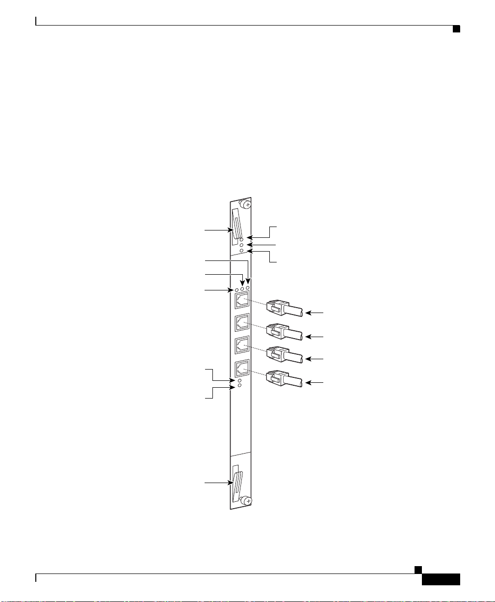
Chapter 2 Cabling the CSS
Figure 2-10 illustrates the SCM front panel connectors and LED s.
Figure 2-10 Switch Control Module Connectors and LEDs
Cabling the CSS 11800 Modules
• One RJ-45 Building Integra ted Timing Supply (BIT S) Cloc k
RS-422 connector
• Power, Status, and Active module LEDs
• Duplex, 10/100, and Active LE Ds for the Fast Ether net port
• Power Supply 1 and 2 LEDs
Module ejector
Link LED
10/100 LED
Duplex LED
Power supply 1 LED
Power supply 2 LED
Module ejector
Power LED
Status LED
Active LED
10/100 Ethernet connector
Console connector
Diag connector
Timing BITS connector
49583
78-15146-02
Cisco 11000 Series Content Services Switch Hardware Installation Guide
2-13
Page 62

Cabling the CSS 11800 Modules
Switch Control Module LEDs
The SCM front panel L EDs indic ate m odule a nd c on figuration status. Table 2-4
describes the SCM LE Ds a nd the ir indications.
Table 2-4 Switch Control Module LED Descriptions
LED Name Color LED Status Indicates
Power Green Off M odule does not ha ve power
Status Yellow Off Module is operational
Active Green Off SCM is passive
Duplex
(Ethernet
Management Port)
10/100
(Ethernet
Management Port)
Link
(Ethernet
Management Port)
PS 1
(Power Supply 1)
PS 2
(Power Supply 2)
Chapter2 Cabling the CSS
On Module has power
On Module is experiencing an error
(only when the SCM is active; the
LED is normally yellow when the
SCM is passive)
On SCM is active
Green Off Port is operating at half duplex
On Port is operating at full duplex
Green Off Port is operating at 10 Mbps
On Port is operating at 100 Mbps
Green Off No link
On Link established
Blinking Link established and constan t
activit y
Green Off Power su p pl y is not functi o ni ng
On Power supply is functioning
Green Off Power su p pl y is not functi o ni ng
On Power supply is functioning
2-14
Cisco 11000 Series Content Services Switch Hardware Installation Guide
78-15146-02
Page 63

Chapter 2 Cabling the CSS
Configuring a Terminal to the SCM Console Port
This section describes how to configure a terminal connected to the SCM console
port. Initially, the terminal settings must match the CSS default settings as
specified in Table 2-5.
Table 2-5 CSS Console Port Default Settings
Parameter Default Setting
Baud Rate 9600
Data Bits 8
Flow Control none
Parity none
Stop Bits 1
Terminal Type VT100/ANSI
Fast Ethernet Module Connectors and LEDs
Cabling the CSS 11800 Modules
78-15146-02
The FEM is available in two models:
• Model CSS8-IOM-8FE contains eight auto -sensing RJ-45 Fast Ethern et
10/100-Mbps 10BASE-T /100B ASE -TX conn ec tors
• Model CSS8-IOM-6 /2 FE co ntai ns six au to-se nsin g R J-45 Fa st E t herne t
10/100-Mbps 10BASE-T /100B ASE -TX conn ector s a nd tw o 1 00BASE -FX
SC fiber connecto rs
Cisco 11000 Series Content Services Switch Hardware Installation Guide
2-15
Page 64

Cabling the CSS 11800 Modules
Each model contains Power, Status, and Ready LEDs for module status and
Duplex, Speed, and Link LEDs for each of the eight connectors. Figure 2-11
illustrates the LEDs and connectors on the 8-port FEM.
Figure 2-11 8-Port Fast Ethernet Module Connectors and LEDs
Chapter2 Cabling the CSS
Module ejector
10/100 LEDs
Duplex LEDs
Module ejector
Power LED
Status LED
Ready LED
Link LEDs
RJ-45
10BASE-T/100BASE-TX
connectors
49584
2-16
Cisco 11000 Series Content Services Switch Hardware Installation Guide
78-15146-02
Page 65

Chapter 2 Cabling the CSS
Figure 2-12 illustrates the LEDs and connectors on the FEM mode l
CSS8-IOM-6/2/FE.
Figure 2-12 Fast Ethernet Module with 6 10BASE-T/100BASE-TX Connectors,
Cabling the CSS 11800 Modules
Two 100BASE-FX SC Fiber Connectors, and LEDs
Module ejector
10/100 LEDs
Duplex LEDs
Module ejector
Power LED
Status LED
Ready LED
Link LEDs
RJ-45
10BASE-T/100BASE-TX
connectors
Fiber SC connectors
78-15146-02
49585
Cisco 11000 Series Content Services Switch Hardware Installation Guide
2-17
Page 66
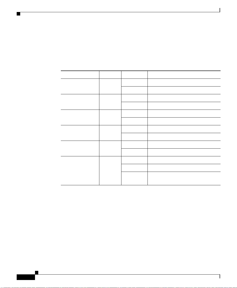
Cabling the CSS 11800 Modules
Fast Ethernet Module LEDs
The FEM front panel LEDs indicate mod ule and networ k status. Table 2-6
describes the FEM LEDs.
Table 2-6 Fast Ethernet Module LED Descriptions
LED Name Color LED Status Indicates
Power Green Off Module does not have power
Status Yellow Off Module is operational
Ready Green Off Module not initialized
Duplex
(FES Ports 1 to 8 )
10/100
(FES Ports 1 to 8 )
Link
(FES Ports 1 to 8 )
Chapter2 Cabling the CSS
On Module has power
On Module is experiencing an erro r
On Module initialized and ready
Green Off Port is operating at half duplex
On Port is operating at full duplex
Green Off Port is operating at 10 Mbps
On Port is operating at 100 Mb ps
Green Off No link established
On Link established
Blinking Link established and activity
detected
Gigabit Ethernet Module Connectors and LEDs
The GEM is avail able i n two mo dels :
• Model CSS8-IOM-4GE/8 con tains f our Giga bit In terfac e Conv er ter (GBIC )
slots and 8 MB Flow Ca ch e SRA M me mo ry suppor ting u p to 6 4,0 00
simultaneous flows. CSS8-GBIC-SX is sold sepa rately.
• Model CSS8-IOM-4GE/16 contains four GBIC slots and 16 MB Flow Cache
SRAM memory suppor ting up to 1 28,000 simu ltane ous flo ws.
CSS8-GBIC-SX is sold separately.
Cisco 11000 Series Content Services Switch Hardware Installation Guide
2-18
78-15146-02
Page 67
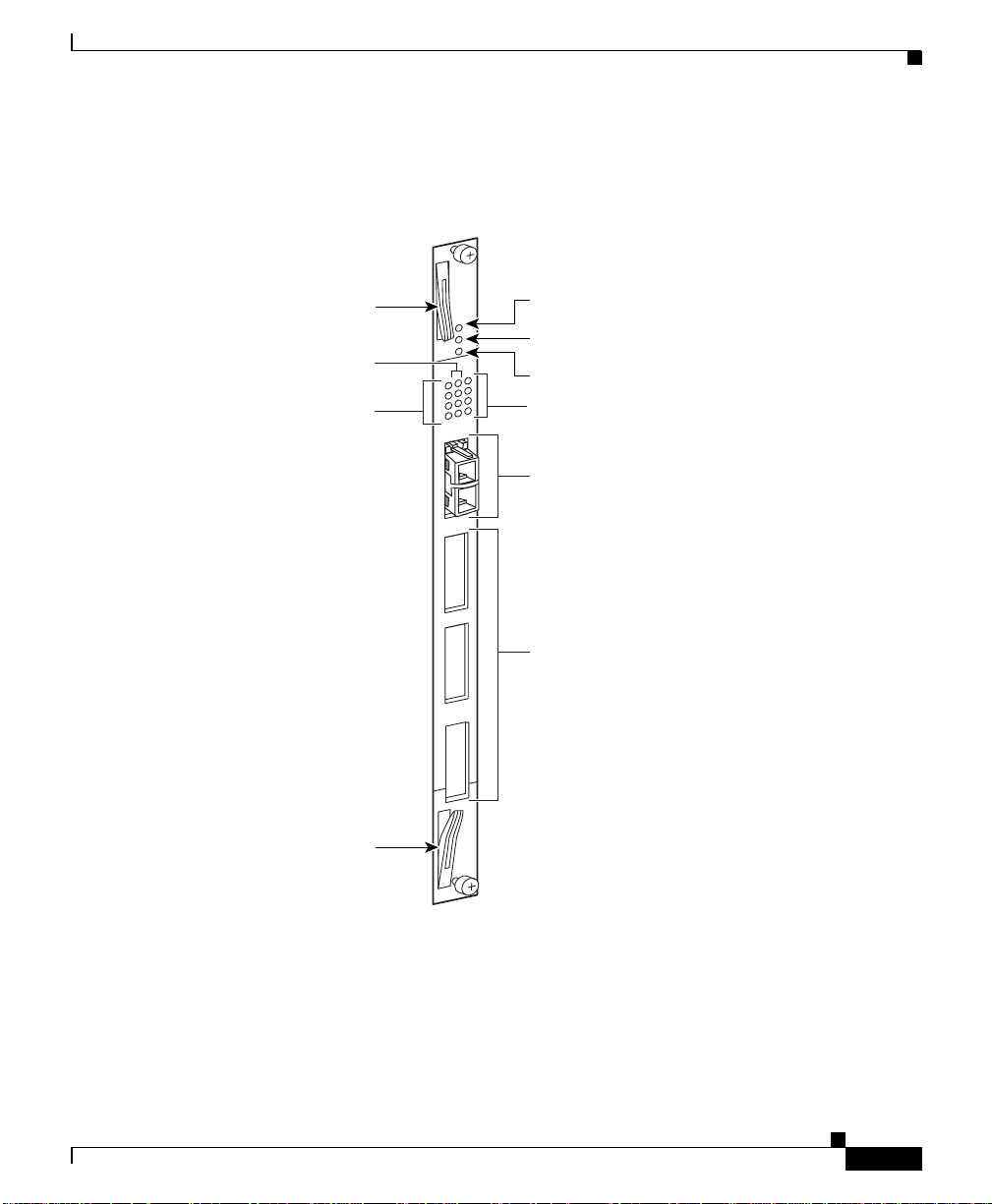
Chapter 2 Cabling the CSS
Figure 2-13 illustrates the LEDs and connectors on a GEM.
Figure 2-13 Gigabit Ethernet Module Connectors and LEDs
Cabling the CSS 11800 Modules
Module ejector
Receive LEDs
Transmit LEDs
Module ejector
Power LED
Status LED
Ready LED
Link/sync LEDs
Gigabit interface
converter (GBIC)
1
SC fiber connectors
(top - receive,
bottom - transmit)
2
Ports 2 through 4
for additional
3
4
GBIC connectors
78-15146-02
49586
Cisco 11000 Series Content Services Switch Hardware Installation Guide
2-19
Page 68

Cabling the CSS 11800 Modules
Gigabit Ethernet Module LEDs
The GEM front panel LEDs indicate module status (Power, Status, and Ready
LEDs) and network status for each of the connectors (Transmit, Receive, and Link
LEDs). Table 2-7 describes the GEM LEDs.
Table 2-7 Gigabit Etherne t Module LED Desc riptions
LED Name Color L ED Status Indicates
Power Green Off Module does not have pow er
Status Yellow Off Module is operatio nal
Ready Green Off Module not initialized
Tx (Transmit)
(Ports 1 to 4)
Rx (Receive)
(Ports 1 to 4)
Link/Sync
(Ports 1 to 4)
Chapter2 Cabling the CSS
On Module has power
On Module is exp er ien cing a n er ror
On Module initialized and ready
Green Off No transmit packet activity
Blinking Transmit activity detected
Green Off No receive packet acti vity
Blinking Receive activity detected
Green Off No link
On Link exists and synchronization
achieved
Blinking Link exists but not synchronized
2-20
Cisco 11000 Series Content Services Switch Hardware Installation Guide
78-15146-02
Page 69

Chapter 2 Cabling the CSS
Cabling the CSS 11800 Modules
Switch Fabric Module (SFM and SFM2) Connectors and LEDs
The Switch Fabric Module (SFM or SFM2) sets up and tears down flow
connections, monitors switch operation, and performs switch functions. The I/O
modules use the SFM proc es sors to per form ro uting function s, inclu ding
resolution of unknown addre sses, route determinations, protocol processing, and
other exception eve nts.
Each module provides 10-Gbps switch control element for switching
functionality and flow processing for four I/O modules. You can install a second
active module to service four additional I/O modules. Both active module s are on
simultaneously in the CSS 11800. The c hassis ena bles yo u to conf igure two
additional passive modules fo r re dund ancy. Therefore, you c an c onfigur e a total
of four SFMs or SFM2s in a ch assis, o f wh ich only tw o wo uld be a ctive a t any
time.
Note When the CSS 11800 contains two passive SFMs and an active SFM switchover
occurs, both passive SFMs switchover to become active SFMs.
78-15146-02
You can mix SFMs with SFM2s in the s ame CSS 11800 chassis. H owever, you
must use the same type module as the active SFM and as the passive SFM.
The Switch Fabric Module (SFM and SFM2) contains Pow er, Status, and Active
LEDs. The SFM has four RJ-45 RS-232 Console and Diag connectors (all of these
connectors are reserved fo r field servic e diagnostic use only).
Cisco 11000 Series Content Services Switch Hardware Installation Guide
2-21
Page 70
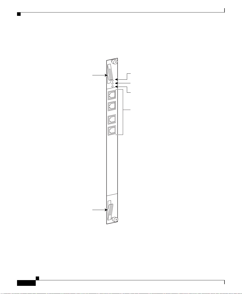
Cabling the CSS 11800 Modules
Figure 2-14 illustrates the SFM front panel LEDs and connectors.
Figure 2-14 Switch Fabric Module Connectors and LEDs
Chapter2 Cabling the CSS
Module ejector
Module ejector
Power LED
Status LED
Active LED
Debug console
and diag console
2-22
49587
The SFM2 contains two RJ-45 RS-232 Diag1 and Di ag 2 conne cto rs, com bining
both Console and Diag fu nctio ns on ea ch c on nector (all o f thes e co nnec tors are
reserved for field servic e diagno stic us e only ).
Cisco 11000 Series Content Services Switch Hardware Installation Guide
78-15146-02
Page 71

Chapter 2 Cabling the CSS
Note These connectors are for serial data only and are not compatible with Ethernet
RJ-45 cable connectors.
Figure 2-15 illustrates the SFM2 (mod el C SS8-SFM2) f ront pa nel L EDs an d
connectors.
Figure 2-15 Switch Fabric Module 2 Connectors and LEDs
Cabling the CSS 11800 Modules
Module ejector
Module ejector
Diag 1
Diag 2
Power LED
Status LED
Active LED
Console/diag connectors
(Diag 1 and Diag 2)
78-15146-02
49588
Cisco 11000 Series Content Services Switch Hardware Installation Guide
2-23
Page 72

Cabling the CSS 11800 Modules
SFM and SFM2 LEDs
The SFM and SFM2 front panel LEDs indicate operating and configuration status.
Table 2-8 describes the SFM LE Ds.
Table 2-8 Switch Fabric Module LED Descriptions
LED Name Colo r LED Status Indicates
Power Green Off Module does not have power
Status Yellow Off Modu le is operational
Active Green Off SFM is passive
Chapter2 Cabling the CSS
On Module has power
On Module is experiencing an error (only
when the SF M is ac tiv e; th e LED is
normally yellow when the SFM is
passive)
On SFM is active
Internal Disk Module LEDs
The Internal Disk Module (I DM) in slot 15 contai ns Power, Status, and Active
LEDs. Figure 2-16 illustrates the IDM front panel LEDs. The LEDs apply to both
the flash-based (mod el CSS8-ID M-M EM-FD ) or ha rd d rive -based (mo de l
CSS8-IDM-MEM-H D) IDM.
Cisco 11000 Series Content Services Switch Hardware Installation Guide
2-24
78-15146-02
Page 73

Chapter 2 Cabling the CSS
Figure 2-16 Internal Disk Module LEDs
Cabling the CSS 11800 Modules
Module ejector
Power LED
Status LED
Active LED
78-15146-02
Module ejector
49589
Cisco 11000 Series Content Services Switch Hardware Installation Guide
2-25
Page 74

Connecting Power Cord s
Internal Disk Module LEDs
The CSS 11800 IDM front panel LEDs indicate operating an d activity status.
Table 2-9 describes the IDM LEDs.
Table 2-9 CSS 11800 Internal Disk Module LED Descriptions
LED Name Color LED Status Indicates
Power Green Off IDM does not have power
Status Green Off IDM device 0 is selected
Active Green Off No activity
Chapter2 Cabling the CSS
On IDM has power
On Reserved for future use
On Constant activity
Blinking Activity
Connecting Power Cords
The CSS 1105 0 mo dels are p ower ed by an AC powe r supp ly. The CSS 11150 and
CSS 11800 are powered by either an AC or DC power supply. Before you install
the AC or DC power cord, ensure that you have read Appendix A, Specifications
for electrical specifications. The following sections describe:
• Connecting a CSS 11050 or CSS 11150 Power Cord
• Connecting a CSS 11800 Power Cord
Connecting a CSS 11 050 o r C SS 11 150 P o wer Cord
The following sections provide information on:
• Connecting a CSS 11050 or CSS 11150 AC Power Cord
• Connecting a CSS 11150 DC Power Cord
Note The CSS 11050 is only available in an AC version.
Cisco 11000 Series Content Services Switch Hardware Installation Guide
2-26
78-15146-02
Page 75

Chapter 2 Cabling the CSS
Connecting a CSS 11050 or CSS 11150 AC Power Cord
To connect an AC power cord to a CSS 11050 or CSS 11150:
1. Ensure th at th e CSS p owe r swi tch is in th e 0 (off) position.
2. Attach the power cord to the CSS by plugging the AC power cord connector
into the pow e r re ce pta c le at th e re ar p an el, a s sh ow n in Figu re 2-17.
Figure 2-17 Connecting a CSS 11050 or CSS 11150 AC Power Cord
AC -100 -240 VAC
50 - 60HZ 3.1AMax.
Connecting Power Cords
49590
AC power cord
3. Plug the power cord into a dedicated 3-wi re groundin g receptacle .
4. Switch on the power on the C SS.
Connecting a CSS 11150 DC Power Cord
Before you install a DC power cord, see Appendix A, Specifications for DC
power supply safety warnings.
Warning
Warning
The DC power supply cord requires 18 AWG wire. The CSS 11150 draws a
maximum of 25 amps.
DC systems do not have a power switch. A chassis configured for DC power
requires an external power disconnect device (such as an external circuit
breaker).
Power switch
78-15146-02
Cisco 11000 Series Content Services Switch Hardware Installation Guide
2-27
Page 76
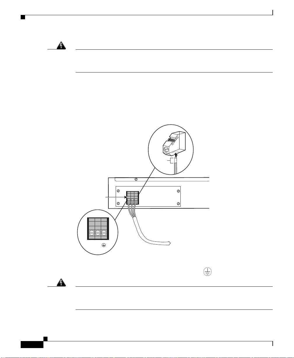
Connecting Power Cord s
59199
Chapter2 Cabling the CSS
Warning
Before performing the DC installation procedure, ensure that power is removed
from the DC circuit. To ensure that all power is off, locate the circuit breaker
that services the DC circuit and switch it off.
To connect the CSS 11150 DC power supply to a po wer so urce :
1. Locate the DC terminal block on the front of the chassis as shown in
Figure 2-18.
Figure 2-18 Location of CSS 11150 DC Power Supply Connectors
.35"
(9mm)
Terminal block
DC -48 input
7.9A Max.
300W Max.
49591
–
+
2. Using a flat-head screwdriver, loosen the captive screws on the three DC
connectors (labeled from left to right, +, –, and , respectively).
Warning
Before installing a wire, ensure that the polarity of the DC connections is
correct. Reversed polarity causes damage to the DC power supply and can
create a dangerous shock hazard.
Cisco 11000 Series Content Services Switch Hardware Installation Guide
2-28
78-15146-02
Page 77

Chapter 2 Cabling the CSS
Table 2-10 CSS 11150 to DC Power Source Cabling
Connecting Power Cords
3. Install the wires into the appropriate connector. Make sure that the
uninsulated part of ea ch wi re is 9m m (0. 35 in.) in len gth.
When installing the wires, always connect the ground wire first. When
disconnecting the wires, alwa ys disconnect the ground wir e last.
The proper power cable wiring between the CSS 11150 and DC power source
is illustrated in Table 2-10.
CSS 11150 DC Power Source
(Ground)
(Ground)
++
––
4. Tighten the captive screws to 5 to 7 inc h- pounds (. 6 to .8 N m ) of torqu e to
secure the wires in the connectors. Ensure the wires are held firmly in place.
Connecting a CSS 11800 Power Cord
The following sections provide information for connecting an AC or DC power
cord to a CSS 11800.
Note For inform ation on insta lling a re dunda nt AC or DC p ower supply, consult the
reference sheet included with the power supply.
Cisco 11000 Series Content Services Switch Hardware Installation Guide
78-15146-02
2-29
Page 78

Connecting Power Cord s
Connecting a CSS 11800 AC Power Cord
To connect an AC power cord to a C SS 11800:
1. Ensure th at th e CSS p owe r swi tch is in th e 0 (off) position.
2. Attach the power cord to the CSS by plugging the AC power cord connector
into the power receptacle at the front of the chassis as shown in Figure 2-19.
Figure 2-19 Connecting a CSS 11800 AC Power Cord
Chapter2 Cabling the CSS
PS1 power switch
PS2 power switch
PS2PS1
3. Plug the power cord into a dedicated 3-wi re groundin g receptacle .
4. Switch on the power on the C SS.
Connecting a CSS 11800 DC Power Cord
Before you install a DC power cord, see Appendix A, Specifications for DC
power supply safety warnings.
Warning
Cisco 11000 Series Content Services Switch Hardware Installation Guide
2-30
The DC power supply cord requires 12 AWG wire. The CSS 11800 draws a
maximum of 25 amps.
PS2 AC
power cord
49592
PS1 AC
power cord
78-15146-02
Page 79

Chapter 2 Cabling the CSS
Connecting Power Cords
Warning
Warning
DC systems do not have a power switch. A chassis configured for DC power
requires an external power disconnect device (such as an external circuit
breaker).
Before performing the DC installation procedure, ensure that power is removed
from the DC circuit. To ensure that all power is off, locate the circuit breaker
that services the DC circuit and switch it off.
To connect the CSS 11800 DC power supply to a p ow er so urce :
1. Locate the DC terminal block on the front of the chassis as shown in
Figure 2-20.
Figure 2-20 Location of CSS 11800 DC Power Supply Connectors
.35"
(9mm)
–
+
78-15146-02
PS1 DC
Terminal block
PS2 DC
Terminal block
49593
Cisco 11000 Series Content Services Switch Hardware Installation Guide
2-31
Page 80
Connecting the Console to the CSS
59199
59199
59199
2. Using a flat-head screwdriver, loosen the captive screws on the three DC
connectors (labeled from left to right, +, –, and , respectively).
Chapter2 Cabling the CSS
Warning
Before installing a wire, ensure that the polarity of the DC connections is
correct. Reversed polarity can cause damage to the DC power supply and can
create a dangerous shock hazard.
3. Install the wires into the appropriate connector. Make sure that the
uninsulated part of ea ch wi re is 9m m (0. 35 in.) in len gth.
When installing the wires, always connect the ground wire first. When
disconnecting the wires, alwa ys disconnect the ground wir e last.
The proper power cable wiring between the CSS 11800 and DC power source
is illustrated in Table 2-11.
Table 2-11 CSS 11800 to DC Power Source Cabling
CSS 11800 DC Power Source
(Ground)
(Ground)
++
––
4. Tighten the captive screws to 5 to 7 inc h- pounds (. 6 to .8 N m ) of torqu e to
secure the wires in the connectors. Ensure the wires are held firmly in place.
Connecting the Console to the CSS
To connect a console to the CSS, attach the console cable (provided in the
accessory kit) to the Console port on the CSS 11050 or CSS 11 150 front panel, or
to the CSS 11800 SCM panel. Your terminal settings must match the following
CSS default settings:
• Baud Rate: 9600
• Data Bits: 8
• Flow Control: none
Cisco 11000 Series Content Services Switch Hardware Installation Guide
2-32
78-15146-02
Page 81
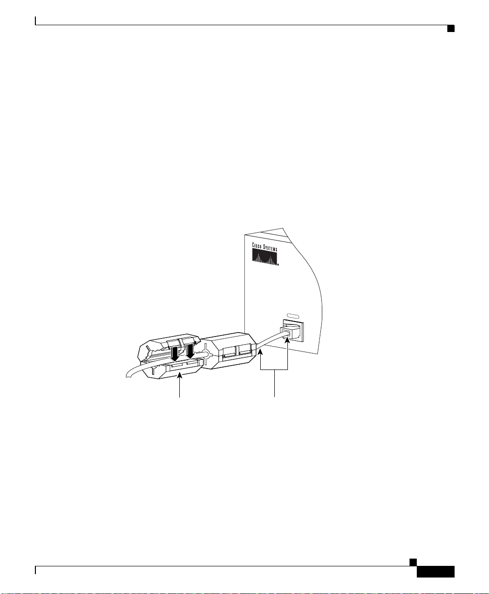
Chapter 2 Cabling the CSS
On the CSS 11050 or 11150 console cable, you must attach two sn ap -on ferrites
provided in the Accessory kit. The ferr ites guarante e proper co nsole operatio n.
To attach the snap-on ferrites (see Figure 2-21):
Figure 2-21 Attaching Ferrites to a CSS 11050 or 11150 Console Cable
Connecting the Console to the CSS
• Parity: none
• Stop Bits: 1
1. Position and attach the first ferrite .75 inches from the RJ-45 connector to the
Console port.
2. Attach the second ferrite behind the first ferrite.
78-15146-02
CONSOLE
59685
Snap-on ferrite
(one of two)
.75 inch space between
the ferrite and the
RJ-45 connector
Cisco 11000 Series Content Services Switch Hardware Installation Guide
2-33
Page 82

Powering Up the CSS
Powering Up the CSS
To power up the AC on a CSS 11050, CSS 11150, or CSS 11800:
1. Attach the power cord to the CSS 11050 or CSS 11150 rear panel AC
connector, or to the CSS 11800 AC connector (see the “Connecting Power
Cords” section earlier in this chapter).
2. Power on the CSS by toggling the power switch to the 1 (on) position.
For DC power on a CSS 11150 or CSS 11800, set the external disconnect device
to the 1 (on) position.
For information concerning the boot process on an 11000 series CSS, refer to the
Content Services Switch Administration Guide
troubleshooting information, see the following section.
Powering Down the CSS
To shutdown a CSS gracefully and avoid introducing lost or frag me nted f iles,
always use the shutdown command prior to removing power from the CSS. This
command is avail able in boot mo de.
Chapter2 Cabling the CSS
. For general hardware
For example:
(config-boot)# shutdown
Once the CSS shuts down all processes, you may remove powe r from the CSS.
Troubleshooting CSS Hardware Components
This section provides ge nera l trouble shoo ting in format ion for the C SS
components. It includes the following sections:
• Troubleshooting the Console Interface
• Troubleshooting the CSS Power Supply
• Troubleshooting the CSS 11800 Modules
Cisco 11000 Series Content Services Switch Hardware Installation Guide
2-34
78-15146-02
Page 83
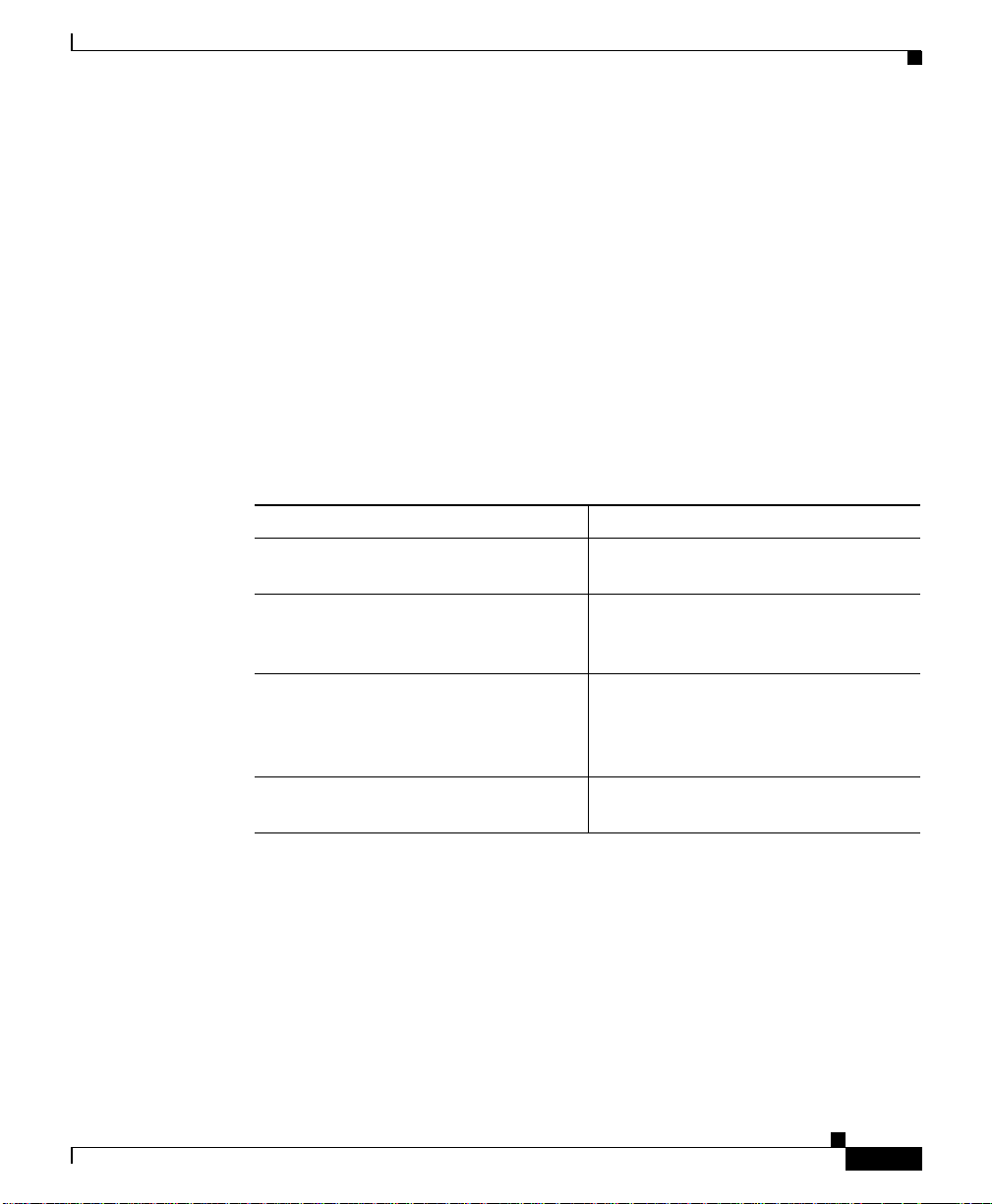
Chapter 2 Cabling the CSS
Troubleshooting the Console Interface
Table 2-12 lists common com munica tions pr oble ms that ma y ex ist betwe en th e
CSS and a console. Ensure the console settings are configured to:
• Baud Rate - 9600
• Data Bits - 8
• Flow Control - none
• Parity - none
• Stop Bits -1
For information on cons ole cable pin outs, se e App en dix B, Cable Pinou ts.
Table 2-12 Troubleshooting the Console Interface
Possible Problem Recommended Ac tion
Nothing appears on the screen. Ensure the RS-232 cable is securely
Characters appear on the screen, but
are garbled.
Abbreviated input is used, but pressing
the tab key does not enter the command
you want.
Random characters are lost. Set the flow command on the console
Troubleshooting CSS Hardware Components
connected to the console po rt.
Verify that the CSS and the console
settings match for baud rate, data bits,
stop bits, and parity.
Ensure that you en ter e nou gh
characters for the CSS to distinguish
between differen t comm ands and
options.
to XON/XOFF.
78-15146-02
Cisco 11000 Series Content Services Switch Hardware Installation Guide
2-35
Page 84

Troubleshooting CSS Hardware Components
Troubleshooting the CSS Power Supply
Power supply status is indic ated b y the:
• Power LED on the CSS 11050 and CSS 11150
• PS1 and PS2 LEDs on the SCM in the CSS 11800
Ta ble 2-13 provides suggestions for correcting problems that may occur with the
CSS 11050 or CSS 11150 power supply.
Table 2-13 Troubleshooting the CSS 11050 or CSS 11150 CSS Power Supply
Chapter2 Cabling the CSS
LED
Name
Power Off No power to power
LED
Status Possible Problem Recommended A ction
Ensure unit has power. Check power
supply.
switch, power cord, and power
source.
Fault in power supply. Replace unit.
Ta ble 2-14 provides suggestions for correcting problems that may occur with the
CSS 1800 power supplies (AC or DC) . The powe r supply sta tus L ED is on the
SCM.
Table 2-14 Troubleshooting the CSS 11800 Power Supply
LED
Name
PS 1
PS 2
LED
Status Poss i ble Problem Recommended A ction
Off No power to prim ar y
power supply.
Ensure unit has power. Check power
switch, power cord, and power
source.
Fault in power supply. Replace the power supply.
The power outputs are
out of limits (possibly
Replace the power supp ly o r rectify
the deficient line condition.
caused by a low input
line).
2-36
Cisco 11000 Series Content Services Switch Hardware Installation Guide
78-15146-02
Page 85

Chapter 2 Cabling the CSS
Note Installing a second CSS 11800 power supply provides power load balancing
between the two power supplies. When you install a seco nd power supply, it
powers on and begins to share the power load au tomatica lly.
Troubleshooting the CSS 11800 Modules
Each CSS 11800 module is equipp ed wi th a te mp eratur e sensor tha t d etects an
over- or under-temper ature condition. If the m odule detects that its temperature is
out of range, it gen erates a lo g m essag e.
Module status is indicated by the Statu s LED on the modu le fro nt p anel. For
information about the m odule L EDs, se e the m odule info rmation e arlier in this
chapter.
Ta ble 2-15 provides suggestions for correcting problems that may occur with the
modules.
Table 2-15 Troubleshooting the CSS 11800 Modules
Troubleshooting CSS Hardware Components
78-15146-02
Symptom Recommended Actio n
System cannot identify
module type.
Remove the module and re-insta ll it to re seat the
module in the backplane connector.
Reload the ADI file.
System cannot find an image
Reload the ADI file.
for the module.
Module failed diagnostic
Replace the module.
(according to the
information in the Boot.log
file).
Cisco 11000 Series Content Services Switch Hardware Installation Guide
2-37
Page 86

Troubleshooting CSS Hardware Components
Table 2-15 Troubleshooting the CSS 11800 Modules (continued)
Symptom Recommended Actio n
You cannot access log or
archive files on the CSS disk
but traffic is still passed in
and out of the CSS.
Replacement IDM does not
initialize.
Chapter2 Cabling the CSS
Replace the Internal Disk M odule. Remo ve the
module and re-install it to reseat the module in
the backplane connector.
If the replacement IDM does not contain the
same version o f the s oftw are th at th e CSS is
currently running, the SCM will not initialize t he
IDM for use. You must reboot the CSS and
configure a primary boot reco rd. You can select
the CSS software currently on the disk or instruct
the CSS where to locate the CSS software ADI
file to install on the disk. If you archived an
offline version of your CSS running-config file,
copy it back onto the CSS.
2-38
Cisco 11000 Series Content Services Switch Hardware Installation Guide
78-15146-02
Page 87

APPENDIX
A
Specifications
This appendix contains the following major sections that list specifications for the
Cisco 11000 Series Content Services Switch es (CSS 11050, CSS 11150, and
CSS 11800):
• Electrical Specifications
• Environmental Specifications
• Physical Specifications
• Module Specifications
• Internal Disk Module Specifications
• Supported Protocols
• DC Power Supply Safety Warnings
• Lithium Battery Disposal Warnings
78-15146-02
Cisco 11000 Series Content Services Switch Hardware Installation Guide
A-1
Page 88

Electrical Speci fi cations
Electrical Specifications
Table A-1 describes the CSS 11050, CSS 11150, and CSS 11800 AC electrical
specifications.
Note The spe cificat ion for the C SS 11800 is for the sy stem , not pe r pow er su pply.
Table A-1 AC Electrical Specification
AC Specification CSS 11050 or CSS 11150 CSS 11800
Input Voltage AC 100 to 240 VAC
Current AC (max@
100VA C)
Power Consumption
(maximum)
Heat Dissipation 683 BTU/hr 3073 BTU/hr
Appendix A Specifications
100 to 240 VAC
50 to 60 Hz
50 to 60 Hz
3.1 Amps 12 Amps
310 Watts 1200 Watts
A-2
Table A-2 describes the CSS 11150 and CSS 11800 DC electrical spec ifications.
Note The spe cificat ion for the C SS 11800 is for the sy stem , not pe r pow er su pply.
Table A-2 DC Electrical Specifications
DC Specification CSS 11150 CSS 11800
Voltage DC -48.0 to -60.0 V DC -48.0 to - 60. 0 VDC
Current DC (maxim um) 8 Am ps 25 Amps
Power Consumption
300 Watts 970 Watts
(maximum)
Heat Dissipation 683 BTU/hr 3073 BTU/hr
Cisco 11000 Series Content Services Switch Hardware Installation Guide
78-15146-02
Page 89

Appendix A Specifications
AC Power Cord Country Requirements
The CSS AC power cord is a three-prong IEC 320-C13 plug that grounds the unit
and polarizes the connection. Table A-3 lists country requirements for plug types
and ratings.
Table A-3 AC Power Cord Country Requirements
Country AC Power Cord Type and Rating
Australia AS 3112-1981 10A/240 VA C
Austria CEE7 Sht V11 16A/240 VAC
Belgium CEE7 Sht V11 16A/240 VAC
British BS 1363A 13A/250 VAC
Canada NEMA 5-15P 12A/125 VAC
China AS 3112-1981 10A/240 VAC
Denmark SRAF 1962/DB 16/87 10A/250 VAC
Finland CEE7 Sht V11 16A/240 VAC
France CEE7 Sht V11 16A/240 VAC
Germany CEE7 Sht V11 16A/240 VAC
India BS 546A 16A/250 VAC
Israel S.I. 32 16A/250 VAC
Italy CEI 23-16 10A/ 250 VAC
Japan JIS 8303 12A/125 VAC
Netherlands CEE7 Sht V11 16A/240 VAC
Norway CEE7 Sht V11 16A/240 VAC
South Africa BS 546A 16A/250 VA C
Sweden CEE7 Sht V11 16A/240 VAC
Switzerland ASE 1 011 (1959) Type 12 10A/250 VAC
U.S.A. NEMA 5-15P 12A/125 VAC
Electrical Specifications
78-15146-02
Cisco 11000 Series Content Services Switch Hardware Installation Guide
A-3
Page 90

Environmental Specifications
Environmental Specifications
Table A-4 describes the CSS 11050, CSS 11150, and CSS 11800 environmental
specifications.
Table A-4 Environmental Specifications
Specification
Ambient Operating Temperature 32 to 104° F (0 to 40° C)
Relative Humidity 5 to 95% (non-condensing)
Ambient Storage Temperature 23 to +149° F (-5 to 65° C)
Physical Specifications
Table A-5 describes the CSS 11050, CSS 11150, and CSS 11800 physical
specifications.
Appendix A Specifications
CSS 11050 or
CSS 11150 CSS 11800
A-4
Table A-5 Physical Specifications
Specification CSS 11050 or CSS 11150 CSS 11800
Chassis Dimensions (H x
W x D)
Chassis Shipping Weight 23 lbs. 105 lbs. (base system
Chassis Weight Fully
Configured
Cisco 11000 Series Content Services Switch Hardware Installation Guide
2.62” x 17.1” x 1 5” 25.25” x 17.1” x 12. 5”
16 lbs. 72 lbs. (base system
containing one power
supply, one SFM or
SFM2, one SCM, IDM)
containing one power
supply, one SFM or
SFM2, one SCM, IDM)
78-15146-02
Page 91
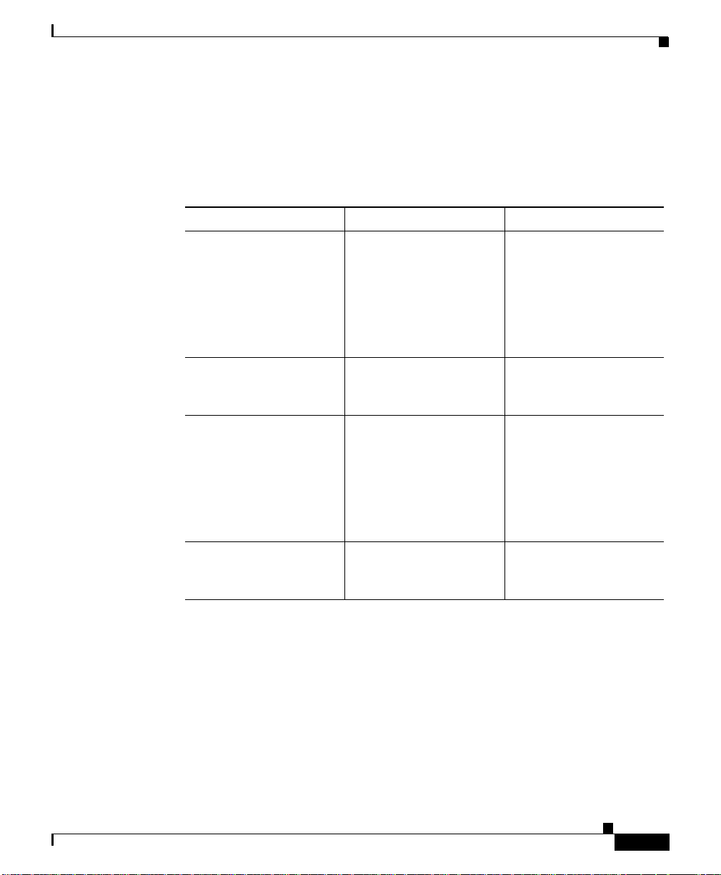
Appendix A Specifications
Module Specifications
Table A-6 describes module general specifications.
Table A-6 Module General Specifications
Specification CSS 11050 or CSS 11150 CSS 11800
Slot Configuration Fixed configuration 8 slots for I/O modules
Switch Bandwidth 5 GB 20 GB (base)
CPU Memory (DRAM) CSS 11050
128 MB
Module Specifications
2 slots for SCMs
(1 active, 1 passive)
4 slots for SFMs or
SFM2s (2 active,
2 p assive)
1 slot for the IDM
20 GB 1:1 optional
redundancy
Switch Control Module
128 MB
78-15146-02
Common Pack et
Memory (SRAM)
Cisco 11000 Series Content Services Switch Hardware Installation Guide
CSS 11150
128 MB (base) wit h a
maximum of 256 MB
Per System
6 MB
Switch Fabric Module
(SFM or SFM 2)
256 MB (128 MB pe r
Switch Fabric Processor)
Switch Control Module
Per System
12 MB
A-5
Page 92
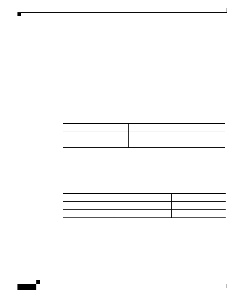
Internal Disk Module Specifications
Internal Disk Module Specifications
This section provides the following specifications for the Internal Disk Module
(IDM).
• Power
• General
IDM Power Requirements
Table A-7 describes the I DM powe r require ments.
Table A-7 IDM Power Requirements
Power Requirements Internal Disk Module
+12V +/- 5% 1.2 Amps Max
+5V +/- 5% .5 Amps Max
Appendix A Specifications
IDM General Specifications
Table A-8 defines IDM general specifications.
Table A-8 IDM General Specifications
Specification Hard Disk Flash Disk
Capacity 1.08 GB minimum 350 MB minimum
Interface EIDE or ATA-3 IDE
Cisco 11000 Series Content Services Switch Hardware Installation Guide
A-6
78-15146-02
Page 93

Appendix A Specifications
Supported Protocols
The CSS supports the following protocols:
• Transport
• Network
• Routing
• Gateway
• Application
• Network Utilities
• Network Management
Transport
The CSS supports the following transport protoc ols:
• TCP
Supported Protocols
Network
78-15146-02
• UDP
The CSS supports the following network protocols:
• Internet Protocol (IP)
• ICMP
• Address Resolution Protocol (ARP)
• Inverse ARP
Cisco 11000 Series Content Services Switch Hardware Installation Guide
A-7
Page 94

Supported Protocols
Routing
Gateway
Application
Appendix A Specifications
The CSS supports the following routing protocols:
• RIP I
• RIP II
• OSPF Version 2
The CSS supports Ne twork Add ress Translation (NAT), per RFC 1631 gateway
protocol.
The CSS supports the following application protoc ols:
• HTTP 1.0, HTTP 1.1
• TELNET
• FTP, TFTP
• RTP
Network Utilities
The CSS supports the following network utility protocols:
• DNS Client
• Radius Client
• HTTP Client
• FTP Daemon
Cisco 11000 Series Content Services Switch Hardware Installation Guide
A-8
78-15146-02
Page 95

Appendix A Specifications
Network Management
The CSS supports the fo llowing networ k m anag ement protoc ols:
• SNMP v1
• SNMP v2
DC Power Supply Safety Warnings
DC Power Supply Safety Warnings
Warning
The DC power supply must be installed in restricted access areas only (for
example, dedicated equipment rooms, equipment closets) in accordance with
articles 110-16, 110-17, and 110-18 of the national electric code, ANSI/NFPA 70.
Connect a DC CSS 11150 or CSS 11800 to a -48 VDC source that is electrically
isolated from the AC power source and is reliably grounded to earth.
This equipment is designe d to pe rmit the con nection of the g rounde d co ndu ctor
of the DC supply circuit to the grounding conductor at th e equipmen t. If this
connection is made, all of the following conditions must be met:
• This equipment shall be connected directly to the DC supply system
grounding electrode conductor or bonding jumper from a grounding terminal
bar or bus to wh ich the D C supply sy stem g rounding e lec trode c onducto r is
connected.
• This equipment shall be located in the same immediate area as any othe r
equipment that has a connection between the grounded conductor of the same
DC supply circuit and the grounding co nductor, and also the poin t of
grounding of the DC system. The DC system shall not be grounded
elsewhere.
• The DC supply source is to be located within the same premises as the
equipment.
• There shall be no switching or disconnec tin g devices in the grounded circuit
conductor between the DC source an d the point of connec tion of the
grounding electrode conductor.
78-15146-02
Cisco 11000 Series Content Services Switch Hardware Installation Guide
A-9
Page 96

Lithium Battery Disposal Warnings
Appendix A Specifications
Warning
A readily accessible disconnect device must be provided in the fixed wiring for
a DC power supply. It must be suitable for the rated voltage and current
specified.
Lithium Battery Disposal Warnings
The SCM contains a small lithium battery. Some jurisdictions restrict the ways in
which items containing lithium batteries may be disposed. In particular, lithium
batteries or products containing lithium batteries may never be disposed of in an
unregulated fire . Other re stri ction s might apply.
Warning
Waarschuwing
Varoitus
Attention
Ultimate disposal of this product should be handled according to all national
laws and regulations.
Dit produkt dient volgens alle landelijke wetten en voorschriften te worden
afgedankt.
Tämän tuotteen lopullisesta hävittämisestä tulee huolehtia kaikkia
valtakunnallisia lakeja ja säännöksiä noudattaen.
La mise au rebut définitive de ce produit doit être effectuée conformément à
toutes les lois et réglementations en vigueur.
A-10
Warnung
Avvertenza
Advarsel
Cisco 11000 Series Content Services Switch Hardware Installation Guide
Dieses Produkt muß den geltenden Gesetzen und Vorschriften entsprechend
entsorgt werden.
L'eliminazione finale di questo prodotto deve essere eseguita osservando le
normative italiane vigenti in materia.
Endelig disponering av dette produktet må skje i henhold til nasjonale lover
og forskrifter.
78-15146-02
Page 97

Appendix A Specifications
Lithium Battery Disposal Warnings
Aviso
¡Advertencia!
Varning!
A descartagem final deste produto deverá ser efectuada de acordo com os
regulamentos e a legislação nacional.
El desecho final de este producto debe realizarse según todas las leyes y
regulaciones nacionales.
Slutlig kassering av denna produkt bör skötas i enlighet med landets alla
lagar och föreskrifter.
78-15146-02
Cisco 11000 Series Content Services Switch Hardware Installation Guide
A-11
Page 98

Lithium Battery Disposal Warnings
Appendix A Specifications
A-12
Cisco 11000 Series Content Services Switch Hardware Installation Guide
78-15146-02
Page 99

APPENDIX
B
Cable Pinouts
This appendix contains the following majo r sections that list pinouts for the
connectors used with the CSS 11050, CSS 11150, and CSS 11800:
• RJ-45 Fast Ethernet Connector Pinouts
• RJ-45 RS-232 Serial Connector Pinou ts
• RJ-45 to RJ-45 CSS Cisco Co nsole Ad apter Cable
• Custom Cable Pinouts for Attaching the CSS Console Port to a
Communication Server
• RJ-45 Timing BITS Connector Pinouts
• RJ-45 Management Connector Pinouts
78-15146-02
Cisco 11000 Series Content Services Switch Hardware Installation Guide
B-1
Page 100
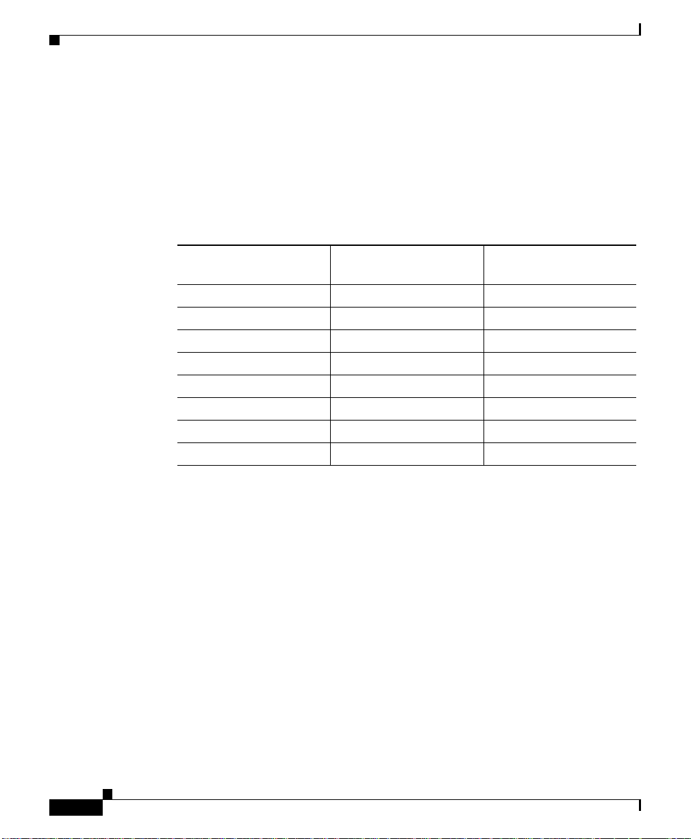
RJ-45 Fast Ethernet Connector Pinouts
RJ-45 Fast Ethernet Connector Pinouts
Table B-1 lists the pinouts for the RJ-45 Fast Ethernet connectors on the:
• CSS 11050 and CSS 11150
• Fast Ethernet Module
Table B-1 RJ-45 Fast Ethernet Connector Pinouts
RJ-45 Fast Ethernet Pin
Signal Name
RX + 1 3
RX - 2 6
TX + 3 1
Unconnected 4 4
Unconnected 5 5
TX - 6 2
Unconnected 7 7
Unconnected 8 8
Numbers Crossover Cable Pinouts
Appendix B Cable Pinouts
B-2
When using the Fast Ethernet connectors to connect the CSS to a:
• Server or a workstation, use a straight-through cable
• Switch or a repeater, use a crossover cable
Cisco 11000 Series Content Services Switch Hardware Installation Guide
78-15146-02
 Loading...