

Page 1

Cisco 10720 Internet Router Installation
and Configuration Guide
Americas Headquarters
Cisco Systems, Inc.
170 West Tasman Drive
San Jose, CA 95134-1706
USA
http://www.cisco.com
Tel: 408 526-4000
800 553-NETS (6387)
Fax: 408 527-0883
Customer Order Number: DOC-7813062=
Text Part Number: 78-13062-10
Page 2

THE SPECIFICATIONS AND INFORMATION REGA RDING THE P RODUCTS IN THIS MANUAL ARE SUBJECT TO CHANGE W ITH OUT NOT ICE. A LL
STATEMENTS, INFORMATION, AND RECOMMENDATIONS IN THIS MANUAL ARE BELIEVED TO BE ACCURATE BUT ARE PRESENTED WITHOUT
WARRANTY OF ANY KIND, EXPRESS OR IMPLIED. USERS MUST TAKE FULL RESPONSIBILIT Y FOR THEIR APPLICATION OF ANY PRODUCTS.
THE SOFTWARE LICENSE AND LIMITED WARRA NTY FO R THE A CCOMPA NYING PRODUCT A RE SET FORTH IN T HE INFORM ATION P ACKET THAT
SHIPPED WITH THE PRODUCT AND ARE INCORPORATED HEREIN BY THIS REFERENCE. IF YOU ARE UNABLE TO LOCATE THE SOFTWARE LICENSE
OR LIMITED WARRANTY, CONTACT YOUR CISCO REPRESENTATIVE FOR A COPY.
The following information is for FCC compliance of Class A devices: This equipment has been tested and found to comply with the limits for a Class A di gital device, pursuant
to part 15 of the FCC rules. These limits are designed to provide reasonable protection against harmful interference when the equipment is operated in a commercial
environment. This equipment generates, uses, and can radiate radio-frequency energy and, if not installed and used in accordance with the instruction manual, may cause
harmful interference to radio communications. Operation of this equipment in a residential area is likely to cause harmful interference, in which case users will be required
to correct the interference at their own expense.
The following information is for FCC compliance of Class B devices: The equipment described in this manual generates and may radiate radio-frequency energy. If it is not
installed in accordance with Cisco’s installation instructions, it may cause interference with radio and television reception. This equipment has been tested and found to
comply with the limits for a Class B digital device in accordance with the specifications in part 15 of the FCC rules. These specifications are designed to provide reasonable
protection against such interference in a residential installation. However, there is no guarantee that interference will not occur in a particular installation.
Modifying the equipment without Cisco’s written authorization may result in the equipment no longer complying with FCC requirements for Class A or Class B digital
devices. In that event, your right to use the equipment may be limited by FCC regulations, and you may be required to correct any interference to radio or television
communications at your own expense.
You can determine whether your equipment is causing interference by turning it off. If the interference stops, it was pr obabl y caused by the Cisco equipment or one of its
peripheral devices. If the equipment causes interference to radio or television reception, try to correct the interference by using one or more of the following measures:
• Turn the television or radio antenna until the interference stops.
• Move the equipment to one side or the other of the television or radio.
• Move the equipment farther away from the television or radio.
• Plug the equipment into an outlet that is on a different circuit from the television or radio. (That is, make certain the equipment and the television or radio are on circuits
controlled by different circuit breakers or fuses.)
Modifications to this product not authorized by Ci sco Systems, Inc. could void the FCC approval and negate your auth ority to op erate the product.
The Cisco implementation of TCP header compression is an adaptation of a program developed by the University of California, Berkeley (UCB) as part of UCB’s public
domain version of the UNIX operating system. All rights reserved. Copyright © 1981, Regents of the University of California.
NOTWITHSTANDING ANY OTHER WARRANTY HEREIN, ALL DO CUMENT FILES AND SOFTW ARE OF THESE SUPPL IERS ARE PROVIDED “AS IS” WITH
ALL FAULTS. CISCO AND THE ABOVE-NAMED SUPPLIERS DISCLAIM AL L WARRANTIES, EX PRESSED OR
LIMITATION, THOSE OF MERCHANTABILITY, FITNESS FOR A PARTICUL AR PURPOSE AND NON INFRINGEMENT OR ARISIN G FROM A COURSE OF
DEALING, USAGE, OR TRADE PRACTICE.
IN NO EVENT SHALL CISCO OR ITS SUPPLIERS BE LIABLE FOR ANY INDIRECT, SPECIAL, CONSEQUENTIAL, OR INCIDENTAL DAMAGES, INCLUDING,
WITHOUT LIMITATION, LOS T PROFITS OR LOSS OR DAMAGE TO DATA ARISIN G OUT OF THE US E OR INABILI TY TO USE THIS MA NUAL, EVEN I F CISCO
OR ITS SUPPLIERS HAVE BEEN ADVISED OF THE POSSIBILITY OF SU CH DAMA GES.
CCVP, the Cisco Logo, and the Cisco Square Bridge logo are trademarks of Cisco Systems, Inc.; Changing the Way We Work, Live, Play, and Learn is a service mark of
Cisco Systems, Inc.; and Access Registrar, Aironet, BPX, Catalyst, CCDA, CCDP, CCIE, CCIP, CCNA, CCNP, CCSP, Cisco, the Cisco Certified Internetwork Expert logo,
Cisco IOS, Cisco Press, Cisco Systems, Cisco Systems Capital, the Cisco Systems logo, Cisco Unity, Enterprise/Solver, EtherChannel, EtherFast, EtherSwitch, Fast Step,
Follow Me Browsing, FormShare, GigaDriv e, Giga Stack, Ho meLin k, Inte rnet Quo tient , IOS, i Phone, IP/TV, i Q Expe rtise, the i Q logo, iQ Net Readiness Scorecard, iQuick
Study, LightStream, Linksys, MeetingPlace, MGX, Networking Academy, Network Registrar, Packet, PIX, ProConnect, RateMUX, ScriptShare, SlideCast, SMARTnet,
StackWise, The Fastest Way to Increase Your Internet Quotient, and TransPath are registered trademarks of Cisco Systems, Inc. and/or its affiliates in the United States and
certain other countries.
All other trademarks mentioned in this document or Website are the property of their respective owners. The use of the word partn er does not imply a part nershi p relati onship
between Cisco and any other company. (0612R)
Cisco 10720 Internet Router Installation and Configuration Guide
Copyright © 2007 Cisco Systems, Inc. All rights reserved.
IMPLIED, INCLUDING, WITHOUT
Page 3

Preface xi
Document Revison History xi
Audience xi
Purpose xii
Organization xii
Conventions xiii
Warning Definition xiii
Related Documentation xix
DPT and SRP xix
Cisco IOS Software Releases xix
Modular QoS xix
Field-Replaceable Units (FRUs) xix
Other xx
CONTENTS
CHAPTER
Obtaining Documentation xx
Cisco.com xx
Product Documentation DVD xx
Ordering Documentation xx
Documentation Feedback xxi
Cisco Product Security Overview xxi
Reporting Security Problems in Cisco Products xxi
Obtaining Technical Assistance xxii
Cisco Technical Support & Documentation We bs ite xxii
Submitting a Service Request xxiii
Definitions of Service Request Severity xxiii
Obtaining Additional Publications and Information xxiv
1 Product Overview 1-1
Product Description 1-1
Physical and Functional Overview 1-2
Cisco 10720 Internet Router Hardware Features 1-3
Hardware Field Replaceable Units 1-4
Uplink Cards 1-4
78-13062-10
Cisco 10720 Internet Router Installation and Configuration Guide
iii
Page 4

Contents
Access Card 1-6
Redundant Power Supply 1-6
Fan Assembly 1-7
Mounts 1-7
Cable Management 1-8
Software Features 1-8
Design Specifications 1-9
Network Equipment Building Systems 1-9
Electromagnetic Compatibility 1-9
Bonding and Grounding 1-9
Environmental Monitoring 1-9
Shock and Vibration 1-9
CHAPTER
2 Preparing for Installation 2-1
Regulatory Compliance and Safety Information 2-1
Warnings and Cautions 2-1
Safety Guidelines 2-2
Maintaining Safety with Electri c ity 2-3
Electrostatic Discharge 2-3
Preventing Electrostatic Discharge 2-3
Laser Safety 2-4
Class 1 Laser Product Warning 2-4
General Laser Warning 2-4
Class 1 LED Product Warning 2-4
Required Tools and Equipment 2-5
Rack-Mounting Guidelines 2-5
Ventilation Guidelines 2-5
Rack-Mounting Clearance Guidelines 2-6
Maintenance Guidelines for Multiple Routers in a Rack 2-6
Environmental Safety Guidelines 2-8
Airflow Guidelines 2-8
Temperature and Humidity Guidelines 2-8
Power Guidelines 2-9
AC-Powered Router 2-9
DC-Powered Router 2-9
Site Wiring Distance and Interference Guidelines 2-10
Electromagnetic Interference 2-10
Distance Limitations for Signaling and Unshielded Conductors 2-10
Cable Management 2-11
Cisco 10720 Internet Router Installation and Configuration Guide
iv
78-13062-10
Page 5

Mounting the Router 2-11
Cisco IOS Software Configuration 2-11
Verifying the Contents in the Box 2-11
Site Log Preparation 2-12
Contents
CHAPTER
3 Installing the Cisco 10720 Internet Router 3-1
Setting up the Cisco 10720 Internet Router 3-1
Cable Management 3-2
Rack-Mounting the Router 3-2
Wall-Mounting the Router 3-6
Setting up the Router on a Desktop 3-8
Grounding the Cisco 10720 Internet Router 3-9
Supplemental Unit Bonding and Grounding Guidelines 3-9
SONET Distance Limitations 3-11
Fiber Cables and Connectors 3-11
Connecting Ports on the Uplink Cards 3-12
Installing the OC48 SFP Modules in the RPR/SRP Uplink Card 3-13
Creating a Four-Node DPT Ring 3-14
Creating a Four-Node IEEE 802.17 RPR Mode Ring 3-17
Additional Ports on the Uplink Cards 3-19
Attaching a Terminal Server or Access Server to the Console or AUX Port 3-19
Attaching a Modem to the Console or AUX Port 3-20
Connecting a Desktop Computer, Laptop, or Terminal to the Console or AUX Port 3-21
78-13062-10
Connecting Ethernet Ports on the Access Card 3-22
Installing a Bale Clasp SFP 3-22
Installing a Latch SFP 3-23
In-Band Ethernet Port 3-25
Installing the Cable-Management System 3-25
Turning On Power to the Router 3-26
Connecting the AC Power Supply 3-27
Connecting the DC Power Supply 3-29
Verifying the Router Power Is Turned On 3-32
Initial Setup Configuration 3-32
Configuring the Router 3-32
Configuring Global Parameters Using the Setup Facility 3-33
Host Name 3-33
Assigning Passwords 3-33
Verifying the Cisco 10720 Internet Router LEDs 3-33
Cisco 10720 Internet Router Installation and Configuration Guide
v
Page 6

Contents
Uplink Card System LEDs 3-34
Uplink Card Status LEDs 3-36
Access Card System LEDs 3-38
Access Card Status LEDs 3-39
Additional Configuration Features 3-42
Saving the Configuration to NVRAM 3-42
Using the show Commands 3-42
Using the show running configuration Command 3-42
Using the show version Command 3-44
Using the show environment all Command 3-45
Monitoring Optical Power 3-45
Configuring Basic SRP Functionality 3-46
Configuring POS Functionality 3-46
Configuring Fast Ethernet 3-47
Configuring Gigabit Ethernet 3-47
Configuring TDR on TX Access Card 3-47
Assigning IP Information 3-47
Enabling Write Permission to Bootflash 3-47
Upgrading the Cisco IOS Software Image 3-47
Verifying the Image Is Upgraded 3-48
Upgrading ROM Monitor 3-48
Verifying ROM Monitor Is Upgraded 3-49
CHAPTER
vi
4 Troubleshooting 4-1
Basic Troubleshooting RPR-IEEE for the Uplink Card 4-1
Using the show controller rpr-ieee Command 4-1
Using the show controllers rpr-ieee 1/1 transceiver Command 4-3
Using the show arp Command 4-4
Verifying Clocking 4-5
PASS-THRU Mode 4-5
Verifying the PASS-THRU Mode 4-5
Using the show rpr-ieee topology Command 4-6
Using the show rpr-ieee protection Command 4-6
Fiber Misconnection 4-7
Basic Troubleshooting SRP for the Uplink Card 4-7
Using the show controller srp Command 4-7
Using the show arp Command 4-9
Verifying Clocking 4-9
PASS-THRU Mode 4-9
Cisco 10720 Internet Router Installation and Configuration Guide
78-13062-10
Page 7

Verify the PASS-THRU Mode 4-10
Using the show srp topology Command 4-10
Using the show srp ips Command 4-10
Fiber Misconnection 4-11
Alarm Messages 4-11
Alarm Messages 4-11
Basic Troubleshooting Ethernet for the Access Card 4-19
Verifying Interface Configuration 4-19
FastEthernet/GigabitEthernet Is up 4-20
Line Protocol Is up 4-20
Duplex Mode Setting 4-21
Speed Mode 4-21
Output Hang 4-21
CRC Field Counters 4-21
Late Collision 4-21
Carrier Signal 4-22
Contents
CHAPTER
Cleaning the Fiber-Optic Connections 4-22
5 Maintaining the Cisco 10720 Internet Router 5-1
Overview 5-1
Safety Recommendations 5-1
Required Tools and Equipment 5-2
Tools 5-2
Field-Replaceable Units 5-2
Disconnecting Power from the Router 5-3
Overview 5-3
Disconnect Device Safety Warning 5-3
Tools and Equipment Required 5-4
Powering Down the Router 5-4
Verifying the Router Is Powered Down 5-6
Connecting Power to the Router 5-7
Safety 5-7
Tools and Equipment Required 5-7
Connecting the AC Power Supply 5-7
Connecting the DC Power Supply 5-9
Removing and Installing the Router Chassis Cover 5-13
Safety 5-13
Required Tools and Equipment 5-13
Removing the Router Cover 5-13
78-13062-10
Cisco 10720 Internet Router Installation and Configuration Guide
vii
Page 8

Contents
Installing the Router Cover 5-15
Removing and Installing the Router Fan Assembly 5-16
Safety 5-16
Required Tools and Equipment 5-17
Removing the Fan Assembly 5-17
Installing the Fan Assembly 5-21
Verifying Fan Assembly Functionality 5-26
Troubleshooting the Fan Assembly 5-26
Removing and Installing the Route Processor Memory 5-26
Upgrading and Verifying the Cisco IOS Release 5-27
Upgrading and Verifying the ROMmon Image 5-27
Upgrading the Golden ROMmon Image with FPGA Version 3 5-27
Upgrading the Golden ROMmon Image with FPGA Version 4 5-28
Upgrading the ROMmon Image 5-28
Verifying the ROMmon Image 5-29
Removing the 256-MB Route Processor Memory 5-29
Installing the 512-MB Route Processor Memory 5-32
Checking the 512-MB Route Processor Installation 5-33
Removing and Installing the AC or Dual DC Power Supply 5-34
Safety 5-34
Required Tools and Equipment 5-35
Removing an AC or Dual DC Power Supply 5-35
Installing an AC or Dual DC Power Supply 5-42
Verifying AC or Dual DC Power Supply Functionality 5-46
Removing and Installing an Uplink Card 5-49
Safety 5-49
Required Tools and Equipment 5-49
Removing an Uplink Card 5-50
Removing an SFP 5-50
Installing an Uplink Card 5-55
Installing the OC48 SFP Modules in the RPR/SRP Uplink Card 5-56
Connecting the Optical Cables 5-57
Verifying Uplink Card Functionality 5-57
Troubleshooting the Uplink Card Functionality 5-57
Removing and Installing an Access Card 5-58
Safety 5-58
Required Tools and Equipment 5-58
Removing an SFP 5-58
Removing a Bale Clasp SFP 5-59
Cisco 10720 Internet Router Installation and Configuration Guide
viii
78-13062-10
Page 9

I
NDEX
Contents
Removing a Latch SFP 5-61
Removing the Access Card 5-62
Installing an Access Card 5-64
Installing the SFP Modules on the Access Card 5-65
Verifying Access Card Functionality 5-67
Troubleshooting the Access Card Functionality 5-67
Removing and Installing the Cable-Management System 5-68
Safety 5-68
Required Tools and Equipment 5-68
Removing the Cable-Management System 5-68
Installing the Cable-Management System 5-70
Physical and Environmental Specifications A-1
Power Specifications A-2
78-13062-10
Cisco 10720 Internet Router Installation and Configuration Guide
ix
Page 10

Contents
Cisco 10720 Internet Router Installation and Configuration Guide
x
78-13062-10
Page 11

Preface
Document Revison History
The revision history of this document is provided below beginning with version 78-13062-09.
Version Date Notes
78-13062-09 June 3, 2005 Adding warning statement numbers. cross-referenced to
78-13062-10 January, 2006 Adding two NEBS notes .
the Regulatory Compliance and Safety Information for
the Cisco
10720 Router document.
Audience
The following sections are in this Preface:
• Audience, page xi
• Purpose, page xii
• Conventions, page xiii
• Warning Definition, page xiii
• Related Documentation, page xix
• Obtaining Documentation, page xx
• Documentation Feedback, page xxi
• Cisco Product Security Overview, page xxi
• Obtaining Technical Assistance, page xxii
• Obtaining Additional Publications and Information, page xxiv
The Cisco 10720 Internet Router Installation and Configuration Guide is designed for the person who
will install, configure, and maintain a Cisco 10720 Internet Router. This person typically will have
substantial experience configuring router- or switch-based IP networks, but might or might not have
experience with Cisco products and Cisco-supported protocols.
The user must be familiar with electronic circuitry and wiring practices and have experience as an
electronic or electromechanical technician.
78-13062-10
Cisco 10720 Internet Router Installation and Configuration Guide
xi
Page 12

Preface
Purpose
Purpose
This guide presents hardware installation and basic configuration procedures for the Cisco 10720
Internet Router and includes information on:
• Installing the hardware
• Starting up the router
• Configuring basic functionality
Organization
The Cisco 10720 Internet Router Installation and Configuration Guide is organized as follows:
Chapter/Appendix
Number
Chapter 1 Product Overview Contains a high-level system overview, physical description of the
Chapter 2 Preparing for Installation Contains information on safety, site requirements for power,
Chapter 3 Installing the Cisco 10720
Chapter 4 Troubleshooting Contains procedures for identifying and solving problems that may
Chapter 5 Maintaining the Cisco 10720
Appendix A Technical Specifications Contains Cisco 10720 Internet Router specifications.
Title Description
Preface The Preface contains contact information, related documentation to
assist in advanced configuration tasks, and a subset of translated safety
Internet Router
Internet Router
warnings that can be found in the
Information for the Cisco 10720 Internet Router publication, and other
useful information.
major components of a Cisco 10720 Internet Router, and functional
overview.
environmental safety, cabling, rack-mounting, electrostatic discharge
(ESD), unpacking, and the site log.
Contains the procedures for verifying the Cisco 10720 Internet Router
installation, grounding, cable connection, powering up the router, and
basic configuration.
occur during installation.
Contains information on safety at the field-replaceable unit (FRU) le vel,
removal and replacement procedures for field-replaceable units and
assemblies, and associated procedures to troubleshoot and verify the
FRUs.
Regulatory Compliance and Safety
Cisco 10720 Internet Router Installation and Configuration Guide
xii
78-13062-10
Page 13

Preface
Conventions
This publication uses the following conventions:
• The symbol ^ represents the key labeled Control. For example, the key combination ^z means hold
Command descriptions use these conventions:
• Examples that contain system prompts denote interactive sessions, indicating the commands that
• Commands and keywords are in boldface font.
• Arguments for which you supply values are in italic font.
• Elements in square brackets ([ ]) are optional.
• Alternative but required keywords are grouped in braces ({ }) and separated by vertical bars (|).
Examples use these conventions:
Conventions
down the Control key while you press the z
you should enter at the prompt. The system prompt indicates the current level of the EXEC
command interpreter. For example, the prompt
router# indicates the privileged level. Access to the privileged level usually requires a password.
key.
router> indicates the user level, and the prompt
• Terminal sessions and sample console screen displays are in screen font.
• Information you enter is in boldface screen font.
• Nonprinting characters, such as passwords, are in angle brackets (< >).
• Default responses to system prompts are in square brackets ([ ]).
• Exclamation points (!) at the beginning of a line indicate a comment line.
Warning Definition
Warning
Waarschuwing
IMPORTANT SAFETY INSTRUCTIONS
This warning symbol means danger. You are in a situ ation that could cau se bodily inju ry. Before you
work on any equipment, be aware of the hazards involved with electrical circuitry and be familiar
with standard practices for preventing accidents. Use the statement number provided at the end of
each warning to locate its translation in the translated safety warnings that accompanied this
device.
SAVE THESE INSTRUCTIONS
BELANGRIJKE VEILIGHEIDSINSTRUCTIES
Statement 1071
Dit waarschuwingssymbool betekent gevaar. U verkeert in een situatie die lichamelijk letsel kan
veroorzaken. Voordat u aan enige apparatuur gaat werken, dient u zich bewust te zijn van de bij
elektrische schakelingen betrokken risico's en dient u op de hoogte te zijn van de standaard
praktijken om ongelukken te voorkomen. Gebruik het nummer van de verklaring onderaan de
waarschuwing als u een vertaling van de waarschuwing die bij het apparaat wordt geleverd, wilt
raadplegen.
BEWAAR DEZE INSTRUCTIES
78-13062-10
Cisco 10720 Internet Router Installation and Configuration Guide
xiii
Page 14

Warning Definition
Preface
Varoitus
Attention
Warnung
TÄRKEITÄ TURVALLISUUSOHJEITA
Tämä varoitusmerkki merkitsee vaaraa. Tilanne voi aiheuttaa ruumiillisia vammoja. Ennen kuin
käsittelet laitteistoa, huomioi sähköpiirien käsittelemiseen liittyvät riskit ja tutustu
onnettomuuksien yleisiin ehkäisytapoihin. Turvallisuusvaroitusten käännökset löytyvät laitteen
mukana toimitettujen käännettyjen turvallisuusvaroitusten joukosta varoitusten lopussa näkyvien
lausuntonumeroiden avulla.
SÄILYTÄ NÄMÄ OHJEET
IMPORTANTES INFORMATIONS DE SÉCURITÉ
Ce symbole d'avertissement indique un danger. Vous vous trouvez dans une situation pouvant
entraîner des blessures ou des dommages corporels. Avant de travailler sur un équipement, soyez
conscient des dangers liés aux circuits électriques et familiarisez-vous avec les procédures
couramment utilisées pour éviter les accidents. Pour prendre connaissance des traductions des
avertissements figurant dans les consignes de sécurité traduites qui accompagnent cet appareil,
référez-vous au numéro de l'instruction situé à la fin de chaque avertissement.
CONSERVEZ CES INFORMATIONS
WICHTIGE SICHERHEITSHINWEISE
Dieses Warnsymbol bedeutet Gefahr . Sie be finden sich in einer Situation, die zu V erletzungen führen
kann. Machen Sie sich vor der Arbeit mit Geräten mit den Gefahren elektrischer Schaltungen und
den üblichen Verfahren zur Vorbeugung vor Unfällen vertraut. Suchen Sie mit der am Ende jeder
Warnung angegebenen Anweisungsnummer nach der jeweiligen Übersetzung in den übersetzten
Sicherheitshinweisen, die zusammen mit diesem Gerät ausgeliefert wurden.
Avvertenza
Advarsel
BEWAHREN SIE DIESE HINWEISE GUT AUF.
IMPORTANTI ISTRUZIONI SULLA SICUREZZA
Questo simbolo di avvertenza indica un pericolo. La situazione potrebbe causare infortuni alle
persone. Prima di intervenire su qualsiasi apparecchiatura, occorre essere al corrente dei pericoli
relativi ai circuiti elettrici e conoscere le procedure standard per la prevenzione di incidenti.
Utilizzare il numero di istruzione presente alla fine di ciascuna avvertenza per individuare le
traduzioni delle avvertenze riportate in questo documento.
CONSERVARE QUESTE ISTRUZIONI
VIKTIGE SIKKERHETSINSTRUKSJONER
Dette advarselssymbolet betyr fare. Du er i en situasjon som kan føre til skade på person. Før du
begynner å arbeide med noe av utstyret, må du være oppmerksom på farene forbundet med
elektriske kretser , og kjenn e til standardprosedyrer for å forhindre u lykker. Bruk nummeret i slutten
av hver advarsel for å finne oversettelsen i de oversatte sikkerhetsadvarslene som fulgte med denne
enheten.
TA VARE PÅ DISSE INSTRUKSJONENE
Cisco 10720 Internet Router Installation and Configuration Guide
xiv
78-13062-10
Page 15

Preface
Warning Definition
Aviso
¡Advertencia!
Varning!
INSTRUÇÕES IMPORTANTES DE SEGURANÇA
Este símbolo de aviso significa perigo. Você está em uma situação que poderá ser causadora de
lesões corporais. Antes de iniciar a utilização de qualquer equipamento, tenha conhecimento dos
perigos envolvidos no manuseio de circuitos elétricos e familiarize-se com as práticas habituais de
prevenção de acidentes. Utilize o número da instrução fornecido ao final de cada aviso para
localizar sua tradução nos avisos de segurança traduzidos que acompanham este dispositivo.
GUARDE ESTAS INSTRUÇÕES
INSTRUCCIONES IMPORTANTES DE SEGURIDAD
Este símbolo de aviso indica peligro. Existe riesgo para su integridad física. Antes de manipular
cualquier equipo, considere los riesgos de la corriente eléctrica y familiarícese con los
procedimientos estándar de prevención de accidentes. Al final de cada advertencia encontrará el
número que le ayudará a encontrar el texto traducido en el apartado de traducciones que acompaña
a este dispositivo.
GUARDE ESTAS INSTRUCCIONES
VIKTIGA SÄKERHETSANVISNINGAR
Denna varningssignal signalerar fara. Du befinner dig i en situation som kan leda till personskada.
Innan du utför arbete på någon utrustning måste du vara medveten om farorna med elkretsar och
känna till vanliga förfaranden för att förebygga olyckor. Använd det nummer som finns i slutet av
varje varning för att hitta dess översättning i de översatta säkerhetsvarningar som medföljer denna
anordning.
SPARA DESSA ANVISNINGAR
78-13062-10
Cisco 10720 Internet Router Installation and Configuration Guide
xv
Page 16

Warning Definition
Preface
Aviso
Advarsel
INSTRUÇÕES IMPORTANTES DE SEGURANÇA
Este símbolo de aviso significa perigo. Você se encontra em uma situação em que há risco de lesões
corporais. Antes de trabalhar com qualquer equipamento, esteja ciente dos riscos que envolvem os
circuitos elétricos e familiarize-se com as práticas padrão de prevenção de acidentes. Use o
número da declaração fornecido ao final de cada aviso para localizar sua tradução nos avisos de
segurança traduzidos que acompanham o dispositivo.
GUARDE ESTAS INSTRUÇÕES
VIGTIGE SIKKERHEDSANVISNINGER
Dette advarselssymbol betyder fare. Du befinder dig i en situation med risiko for
legemesbeskadigelse. Før du begynder arbejde på udstyr, skal du være opmærksom på de
involverede risici, der er ved elektriske kredsløb, og du skal sætte dig ind i standardprocedurer til
undgåelse af ulykker. Brug erklæringsnummeret efter hver advarsel for at finde oversættelsen i de
oversatte advarsler, der fulgte med denne enhed.
GEM DISSE ANVISNINGER
Cisco 10720 Internet Router Installation and Configuration Guide
xvi
78-13062-10
Page 17

Preface
Warning Definition
78-13062-10
Cisco 10720 Internet Router Installation and Configuration Guide
xvii
Page 18

Warning Definition
Preface
For a complete list of translated safety warnings, read the Regulatory Compliance and Safety
Information for the Cisco 10720 Internet Router document (Document Number 78-13077-xx) that
accompanies your Cisco 10720 Internet Router. Cisco recommends you read and understand the safety
warnings and guidelines before installing, configuring, or maintaining the router.
Cisco 10720 Internet Router Installation and Configuration Guide
xviii
78-13062-10
Page 19

Preface
Related Documentation
This section provides some reference material out of the Cisco.com library that may be useful for
configuring and maintaining the Cisco 10720 Internet Router.
DPT and SRP
A variety of technical information on Dynamic Packet Transport (DPT) and Spatial Reuse Protocol
(SRP) is at the following URL:
http://www.cisco.com/en/US/tech/tk482/tk611/tsd_technology_support_protocol_home.html
Cisco IOS Software Releases
• Release Notes for Cisco IOS Release 12.0S
• Release Notes for Cisco IOS Release 12.0 ST
Related Documentation
Modular QoS
• Modular QoS CLI Overview section in the Cisco IOS Software Configuration for the Cisco 10720
Internet Router document
• Quality of Service Overview section in the Cisco IOS Software Configuration for the Cisco 10720
Internet Router document
Field-Replaceable Units (FRUs)
• Cisco 10720 Internet Router AC an d DC P ower Supply Repl acement Instructions, document number
78-13100-xx
• Cisco 10720 Internet Router Access Card Installation and Configuration, document number
78-13082-xx
• Cisco 10720 Internet Router Chassis Replacement Instructions, document number 78-13098-xx
• Cisco 10720 Internet Router Fan Assembly Replacement Instructions, document number
78-13099-xx
• Cisco 10720 Internet Router Memory Replacement Instructions, document number 78-16166-xx
• Cisco 10720 Internet Router Cable Management and Rack Mount Installation Instructions,
document number 78-13101-xx
• Cisco 10720 Internet Router Uplink Cards Installation and Configuration, document number
78-13113-xx
78-13062-10
Cisco 10720 Internet Router Installation and Configuration Guide
xix
Page 20

Obtaining Documentation
Other
• Cisco 10720 Internet Router Unpacking Instructions, document number 78-13855-xx
• Regulatory Compliance and Safety Information for the Cisco 10720 Internet Router, document
number 78-13077-xx
• Compressed Air Cleaning Issues for Fiber-Optic Connections
• Inspection and Cleaning Procedures for Fiber-Optic Connections
Obtaining Documentation
Cisco documentation and additional literature are available on Cisco.com. Cisco also provides several
ways to obtain technical assistance and other technical resources. These sections explain how to obtain
technical information from Cisco Systems.
Cisco.com
Preface
You can access the most current Cisco documentation at this URL:
http://www.cisco.com/techsupport
You can access the Cisco website at this URL:
http://www.cisco.com
You can access international Cisco websites at this URL:
http://www.cisco.com/public/countries_languages.shtml
Product Documentation DVD
The Product Documentation DVD is a comprehensive library of technical product documentation on a
portable medium. The DVD enables you to access multiple versions of installation, configuration, and
command guides for Cisco hardware and software products. W it h the D VD, you h av e access to the same
HTML documentation that is found on the Cisco website without being connected to the Internet.
Certain products also have .PDF versions of the documentation available.
The Product Documentation DVD is a vailable as a single unit or as a subscription . Register ed Cisco.com
users (Cisco direct customers) can order a Product D ocumentat ion DVD (product number
DOC-DOCDVD= or DOC-DOCDVD=SUB) from Cisco Marketplace at this URL:
http://www.cisco.com/go/marketplace/
Ordering Documentation
Registered Cisco.com users may order Cisco documentation at the Product Documentation Store in the
Cisco Marketplace at this
http://www.cisco.com/go/marketplace/
Cisco 10720 Internet Router Installation and Configuration Guide
xx
URL:
78-13062-10
Page 21

Preface
Nonregistered Cisco.com users can order tec hnical docu mentatio n from 8:00 a.m. to 5:00 p.m.
(0800 to 1700) PDT by calling 1 866 463-3487 in the United States and Canada, or elsewhere by
calling
011 408 519-5055. You can also order documentation by e-mail at
tech-doc-store-mkpl@external.cisco.com or by fax at 1 408 519-5001 in the United States and Canada,
or elsewhere at 011 408 519-5001.
Documentation Feedback
You can rate and provide feedback about Cisco technical documents by completing the online feedback
form that appears with the technical documents on Cisco.com.
You can submit comments about Cisco documentation b y using the response card (if present) behind the
front cover of your document or by writing to the following address:
Cisco Systems
Attn: Customer Document Ordering
170 West Tasman Drive
San Jose, CA 95134-9883
We appreciate your comments.
Documentation Feedback
Cisco Product Security Overview
Cisco provides a free online Security Vulnerability Policy portal at this URL:
http://www.cisco.com/en/US/products/products_security_vulnerability_policy.html
From this site, you will find information about how to:
• Report security vulnerabilities in Cisco products.
• Obtain assistance with security incidents that involve Cisco products.
• Register to receive security information from Cisco.
A current list of security advisories, security notices, and security responses for Cisco products is
available at this
http://www.cisco.com/go/psirt
To see security advisories, security notices, and security responses as they are updated in real time, you
can subscribe to the Product Security Incident Response T eam Really Simple Syndication (PSIRT RSS)
feed. Information about how to subscribe to the PSIRT RSS feed is found at this
http://www.cisco.com/en/US/products/products_psirt_rss_feed.html
Reporting Security Problems in Cisco Products
Cisco is committed to delivering secure products. We test ou r products internally before we release them,
and we strive to correct all vulnerabilities quickly. If you think that you have identified a vulnerability
in a Cisco product, contact PSIRT:
• For Emergencies only — security-alert@cisco.com
URL:
URL:
An emergency is either a condition in which a system is un der acti ve attack or a condition for wh ich
a severe and urgent security vulnerability should be reported. All other conditions are considered
nonemergencies.
78-13062-10
Cisco 10720 Internet Router Installation and Configuration Guide
xxi
Page 22

Obtaining Technical Assistance
• For Nonemergencies — psirt@cisco.com
In an emergency, you can also reach PSIRT by telephone:
• 1 877 228-7302
• 1 408 525-6532
Tip We encourage you to use Pretty Good Privacy (PGP) or a compatible product (for example, GnuPG) to
encrypt any sensitive info rmation that you send to Cisco. PSIRT can work with information that has been
encrypted with PGP versions
Never use a re voked or an expired encryption ke y. The correct public key to use in your correspondence
with PSIRT is the one linked in the Contact Summary section of the Security Vulnerability Policy page
at this
http://www.cisco.com/en/US/products/products_security_vulnerability_policy.html
The link on this page has the current PGP key ID in use.
If you do not have or use PGP, contact PSIRT at the afor ementioned e- mail ad dresses or phone numbers
before sending any sensitive material to find other means of encrypting the data.
Preface
2.x through 9.x.
URL:
Obtaining Technical Assistance
Cisco Technical Support provides 24-hour-a-day award-winning technical assistance. The Cisco
T echnical Supp ort & D ocumentation w ebsite on Cisco.com features e xt ensi v e o nline su pport resou rces.
In addition, if you have a valid Cisco service contract, Cisco Technical Assistance Center (TAC)
engineers provide telephone support. If you do not have a valid Cisco service contract, contact your
reseller.
Cisco Technical Support & Documentation Website
The Cisco Technical Support & Documentation website provides online documents and tools for
troubleshooting and resolving technical issues with Cisco products and technologies. The website is
available 24 hours a day, at this
http://www.cisco.com/techsupport
Access to all tools on the Cisco Technical Support & Documentation websit e requires a Ci sco .com user
ID and password. If you have a valid service contract but do not have a user ID or password, you can
register at this
http://tools.cisco.com/RPF/register/register.do
Note Use the Cisco Product Identification (CPI) tool to locate your product serial number before submitting
a web or phone request for service. You can access the CPI tool from the Cisco Technical Support &
Documentation website by clicking the Tools & Resources link under Documentation & Tools. Choose
Cisco Product Identification Tool from the Alphabetical Index drop-down list, or click the Cisco
Product Identification Tool link under Alerts & RMAs. The CPI tool offers three search options: by
product ID or model name; by tree view; or for certain products, by copying and pasting show command
URL:
URL:
Cisco 10720 Internet Router Installation and Configuration Guide
xxii
78-13062-10
Page 23

Preface
output. Search results show an illustration of your product with the serial number label location
highlighted. Locate the serial number label on your product and record the in formation before placing a
service call.
Submitting a Service Request
Using the online TAC Service Request Tool is the fastest way to open S3 and S4 service requests. (S3
and S4 service requests are those in which your netw ork is minimally impaired o r for wh ich you require
product information.) After you describe your situation, the TAC Service Request Tool provides
recommended solutions. If your issue is not resolved using the recommended resources, your service
request is assigned to a Cisco engineer. The TAC Service Request Tool is located at this URL:
http://www.cisco.com/techsupport/servicerequest
For S1 or S2 service requests, or if you do not have Internet access, contact the Cisco T AC by telephone.
(S1 or S2 service requests are those in which your production network is down or severely degraded.)
Cisco engineers are assigned immediately to S1 and S2 service requests to help keep your business
operations running smoothly.
To open a service request by telephone, use one of the following numbers:
Asia-Pacific: +61 2 8446 7411 (Australia: 1 800 805 227)
EMEA: +32 2 704 55 55
USA: 1 800 553-2447
For a complete list of Cisco TAC contacts, go to this URL:
Obtaining Technical Assistance
http://www.cisco.com/techsupport/contacts
Definitions of Service Request Severity
To ensure that all service requests are reported in a standard format, Cisco has established severity
definitions.
Severity 1 (S1)—An existing network is down, or there is a critical impact to your business operations.
You and Cisco will commit all necessary resources around the clock to resolve the situation.
Severity 2 (S2)—Operation of an existing network is severely degraded, or significant aspects of your
business operations are negatively af fected by inadequate performance of Cisco products. You and Cisco
will commit full-time resources during normal business hours to resolve the situation.
Severity 3 (S3)—Operational performance of the network is impaired, while most business operations
remain functional. You and Cisco will commit resources during normal business hours to restore service
to satisfactory levels.
Severity 4 (S4)—You require information or assistance with Cisco product capabilities, installation, or
configuration. There is little or no effect on your business operations.
78-13062-10
Cisco 10720 Internet Router Installation and Configuration Guide
xxiii
Page 24

Obtaining Additional Publications and Information
Obtaining Additional Publications and Information
Information about Cisco products, technologies, and network solu tio ns is available from various online
and printed sources.
• The Cisco Product Quick Reference Guide is a handy, compact reference tool that includes brief
product overviews, key features, sample part numbers, and abbreviated technical specifications for
many Cisco products that are sold through channel partners. It is up dated twice a year and includes
the latest Cisco offerings. To order and find out more about the Cisco Product Quick Reference
Guide, go to this URL:
http://www.cisco.com/go/guide
• Cisco Marketplace provides a variety of Cisco books, reference guides, documentation, and logo
merchandise. Visit Cisco Marketplace, the company store, at this
http://www.cisco.com/go/marketplace/
• Cisco Press publishes a wide range of general networking, training and certification titles. Both new
and experienced users will benefit from these publications. For current Cisco Press titles and other
information, go to Cisco Press at this
URL:
http://www.ciscopress.com
• Packet magazine is the Cisco Systems technical user magazine for maximizing Internet and
networking investments. Each quarter, Packet delivers coverage of the latest industry trends,
technology breakthroughs, and Cis co products an d solutions, as well as network deployment and
troubleshooting tips, configuration examples, customer case studies, certification and training
information, and links to scores of in-depth online resources. You can access Packet magazine at
this
URL:
http://www.cisco.com/packet
URL:
Preface
• iQ Magazine is the quarterly publication from Cisco Systems designed to help growing companies
learn how they can use technology to increase revenue, streamline their business, and expand
services. The publication identifies the challenges facing these companies and the technologies to
help solve them, using real-world case studies and business strategies to help readers make sound
technology investment decisions. You can access iQ Magazine at this URL:
http://www.cisco.com/go/iqmagazine
or view the digital edition at this URL:
http://ciscoiq.texterity.com/ciscoiq/sample/
• Internet Protocol Journal is a quarterly journal published by Cisco Systems for engineering
professionals involved in designing, developing, and operating public and private internets and
intranets. You can access the Internet Protocol Journal at this
URL:
http://www.cisco.com/ipj
• Networking products offered by Cisco Systems, as well as customer support services, can be
obtained at this
URL:
http://www.cisco.com/en/US/products/index.html
Cisco 10720 Internet Router Installation and Configuration Guide
xxiv
78-13062-10
Page 25

Preface
Obtaining Additional Publications and Information
• Networking Professionals Connection is an interacti ve website for networking professio nals to share
questions, suggestions, and information about networking products and technologies with Cisco
experts and other networking professionals. Join a discussion at this
http://www.cisco.com/discuss/networking
• World-class networking training is available from Cisco. You can view current offerings at
this
URL:
http://www.cisco.com/en/US/learning/index.html
URL:
78-13062-10
Cisco 10720 Internet Router Installation and Configuration Guide
xxv
Page 26

Obtaining Additional Publications and Information
Preface
Cisco 10720 Internet Router Installation and Configuration Guide
xxvi
78-13062-10
Page 27

Product Overview
The Cisco 10720 Internet Router provides IP services to users at optical speeds at the edge of their
networks. The Cisco
Transport (DPT), Packet over SONET (POS), or IEEE 802.17 RPR technology for optical connectivity.
Each router is equipped with one uplink card and one Ethernet access card.
The Cisco 10720 Internet Router overview is presented in the following sections:
• Product Description, page 1-1
• Physical and Functional Overview, page 1-2
• Design Specifications, page 1-9
Product Description
The Cisco 10720 Internet Router provides Ethernet and OC-48c/STM-16c Internet access. Ethernet
connections are provided by means of copper or optical cables. OC-48c/STM-16c connections are
provided by means of optical cables. The router can interoperate with synchronous optical network
(SONET) transport infrastructure, but it is not required.
CHAPTER
10720 Internet Router provides network access using Ethernet and Dynamic Packet
1
78-13062-10
The Cisco 10720 Internet Router has one card cage with two card slots. The upper slot supports one
uplink card and the lower slot supports one access card. Network interface connectors are located on the
front of the uplink and access cards.
The built-in Flash memory contains a total of 64 MB, with 16 MB dedi cated to a read-only partition t hat
contains the Cisco
read-write partition. The read-write partition contains downloaded Cisco
used to boot up the router.
Additional features of the Cisco 10720 Internet Router are as follows:
• Configuration and administration features, including Telnet and (Cisco Discovery Protocol) CDP
• Serial (AUX) and console ports for local and remote administration
• Remote software download via Trivial File T ransfer Protocol (TFTP) and Remote copy.A UNIX utility
(RCP)
• IP over DCC (data communications channel) for remote management of the Cisco 15104
OC-48/STM16 Optical Regenerator, where applicable
• Optical receive power monitoring support on the OC-48 interface
IOS software image that shipped with the router. There are 48 MB dedicated to a
IOS software images and is
Cisco 10720 Internet Router Installation and Configuration Guide
1-1
Page 28

Physical and Functional Overview
Physical and Functional Overview
The Cisco 10720 Internet Router physical and functional overview is presented in the following
sections, and shown in
• Cisco 10720 Internet Router Hardware Features, page 1-3
• Hardware Field Replaceable Units, page 1-4
• Software Features, page 1-8
Figure 1-1 Cisco 10720 Internet Router: AC (Top) and DC (Bottom) Power Supplies
U
R
E
R
IE
T
H
IV
R
K
T
P
T
R
P
C
A
S
A
X
A
S
R
C
R
A
W
P
Figure 1-1 and Table 1-1:
RESE
T
S
U
C
A
P
ON
T
SO
M
IL
LE
A
E
S
A
C
O
AUX
T
K
M
F
R
R
E
D
E
E
T
R
V
S
W
A
O
Y
O
C
D
C
S
O
P
K
O
T
F
IL
A
)
F
S
G
(
P
D
B
E
R
V
M
A
I
C
0
T
0
C
1
A
/
K
N
I
L
IL
A
F
R
D
E
R
W
A
O
A
C
C
O
P
K
D
C
O
K
O
T
F
D
ON
N
O
T RE
M
O
O
V
R
E
IN
S
ER
T C
A
BLE
W
IT
H T
S
HE PO
W
ER
ON
IN
P
U
T
1
0
0
-2
0
0
- 5
0
/6
0
H
z
2
-5
A
Chapter 1 Product Overview
U
R
E
R
IE
T
H
IV
R
K
T
P
T
R
P
C
A
S
A
X
A
S
R
C
R
A
W
P
R
ESET
S
U
CO
A
P
NSO
T
M
IL
LE
E
S
A
AUX
T
M
F
IN
R
R
O
E
D
K
E
E
T
R
V
S
W
A
O
Y
O
C
S
P
D
C
O
T
F
L
I
A
)
F
S
G
(
P
D
B
E
R
V
M
A
I
C
0
T
0
C
1
A
/
K
N
I
L
IN
O
K
IL
A
F
R
D
E
R
W
A
O
D
C
C
P
O
T
F
DO
N N
O
T R
EM
O
O
VE
R
IN
SER
T C
AB
W
LES
ITH
T
HE
P
O
W
E
R ON
IN
P
U
T
1
0
0
-2
0
0
- 5
0
/6
0
H
z 2
-5
A
Tab le 1-1 Cisco 10720 Internet Router Description
Physical Description
Dimensions 17.25 x 18.25 x 3.5 inches (2 RU)
(43.81 cm x 46.36 cm x 8.89 cm)
W x D x H
Input Power Option 1: AC-input
• 100/240 VAC
• 50/60 Hz
• 300W (Dual)
Option 2: DC-input
• –48/–60 VDC
• 300W (Dual)
57661
Cisco 10720 Internet Router Installation and Configuration Guide
1-2
78-13062-10
Page 29

Chapter 1 Product Overview
Cisco 10720 Internet Router Hardware Features
The Cisco 10720 Internet Router provides two dedicated card slots that are not interchangeable or hot
swappable. (See
access card.
• The uplink card slot provides the following options:
–
DPT or POS/DPT uplink card: one OC-48c/STM-16c DPT port or two POS optical ports with
an aggregate bandwidth of approximately 5 Gbps
–
RPR/SRP uplink card: two OC-48 RPR/SRP (Resilient Packet Ring/Spatial Reuse Protocol)
ports that support small form-factor pluggable (SFP) modules, with an aggregate bandwidth of
approximately 5 Gbps
–
Console/auxiliary card: console and serial ports only
For more information about the uplink card, refer to the Cisco 10720 Internet Router Uplink Car ds
Installation and Configuration publication.
• The Ethernet access card provides either Fast Ethernet or combined Fast Ethernet and Gigabit
Ethernet connectivity. For more information about the access card, refer to the Cisco
Internet
Figure 1-2.) The upper slot contains an uplink card. The lo wer slot cont ains an Ethernet
Router Access Card Installation and Configuration publication.
Physical and Functional Overview
10720
The uplink card with only console and serial ports can be used with one of the Ethernet access cards to
customize the Cisco
Figure 1-2 Uplink Card and Access Card
10720 Internet Router as an Ethernet-only router.
1
U
R
E
R
IE
T
H
IV
R
K
T
P
T
R
P
C
A
S
A
X
A
S
R
C
R
A
W
P
RE
SET
S
U
CO
A
P
NSO
T
M
IL
LE
A
E
S
A
C
O
AU
T
K
M
F
X
R
R
E
D
E
E
T
R
V
S
W
A
O
Y
O
C
D
C
S
O
P
K
O
T
F
L
I
A
)
S
F
G
(
P
D
B
E
R
V
M
A
I
C
0
T
0
C
1
A
/
K
N
I
L
IL
A
F
R
D
E
R
W
A
O
A
C
C
O
P
K
D
C
O
K
O
T
F
DO
N NO
T R
E
M
O
O
V
R
E
INS
ER
T C
ABLE
W
ITH
S
T
HE P
O
W
ER
O
N
IN
P
U
T
1
0
0
-2
0
0
- 5
0/6
0
H
z
2
2
-5
A
57681
1 Uplink card 2 Access card
The main processing board contains a central processing engine that consists of two sets of processors
that manage the control plane traffic and the data plane traffic.
• The Parallel eXpress Forwarding (PXF) network processors manage the data plane and support IP
forwarding as well as advanced QoS features.
• The multiple processors in the PXF process packets simultaneously at the rate of approximately
2 Mpps.
The Cisco 10720 Internet Router can be deployed directly over fiber, thus allowing service providers to
offer IP plus optical access without the need for extensive SONET/Synchronous Digital Hierarchy
(SDH) optical transport infrastructure.
Additional overview information about the router can be located in the Cisco 10720 Internet Router
Overview, which accompanies other marketing materials related to the Cisco 10720 Internet Router.
78-13062-10
Cisco 10720 Internet Router Installation and Configuration Guide
1-3
Page 30

Physical and Functional Overview
Hardware Field Replaceable Units
The Cisco 10720 Internet Router provides dedicated slots for the uplink card and the access card. The
card cage is integrated into a rigid metal frame. The Cisco
are presented in the following sections:
• Uplink Cards, page 1-4
• Access Card, page 1-6
• Redundant Power Supply, page 1-6
• Fan Assembly, page 1-7
• Mounts, page 1-7
• Cable Management, page 1-8
Uplink Cards
The uplink cards are available with one of the following:
• One OC-48c/STM16c DPT uplink fiber-optic port or two POS uplink fiber-optic ports
• Two RPR/SRP uplink fiber-optic ports supporting SFP modules
Chapter 1 Product Overview
10720 Internet Router field replaceable units
• Console and serial (AUX) ports only
There is one slot for an uplink card in the chassis. The cards fit the upper slot of the router chassis. See
Figure 1-3 for an example of a typical DPT uplink card.
For more information about the uplin k cards, versi ons of the u plink cards, and up link card cab ling, refer
to the Cisco 10720 Internet Router Uplink Cards Installation and Configuration publication.
Figure 1-3 DPT Uplink Card (Front View)
TX RX TX RX
10720-SR-LC
ACTIVE
CARRIER
RX PKT
WRAP
PASS THRU
A B
CONSOLE AUX
RESET
OVERTEMP
CARD FAIL
SYSTEM STATUS
POWER
57670
The cable connector is a special LC optical connector. When using the card for DPT connections, the
left port is the spatial reuse protocol (SRP) side A and the right port is SRP side B. When POS
connections are made, the two ports are independent of each other. Each port consists of transmit (TX)
and receive (RX). For additional information, see the
“SONET Distance Limitations” section on
page 3-11. The console/auxiliary card has console and serial (AUX) ports only.
Cisco 10720 Internet Router Installation and Configuration Guide
1-4
78-13062-10
Page 31

Chapter 1 Product Overview
Figure 1-4 RPR/SRP Uplink Card (Front View)
Physical and Functional Overview
1
10720-SR-LC
ACTIVE
RU
T
KT
RIER
OTEC
SS TH
PR
PA
RX P
CAR
1
2 3
1 Span West for RPR mode
6 Span East/Side B RX
4
2
5 6
CONSOLE AUX
7 8 9
RESET
S
TU
P
STA
FAIL
TEM
ER
D
TEM
W
ER
AR
PO
SYS
OV
C
116785
Side A for SRP mode
2 Span West/Side A TX 7 Console port
3 Span West/Side A RX 8 Auxiliary port
4 Span East for RPR mode
9 Reset switch
Side B for SRP mode
5 Span East/Side B TX
The cable connector is a special LC optical connector. The RPR/SRP card uses SFP modules. When
connecting to DPT networks in Resilient Pack Rings (IEEE 802.17 RPR) mode, the left port is span
West, and the right port is span East. When in the Spatial Reuse Protocol (SRP) mode, the left port is
side A, and the right port is side B. Each port consists of transmit (TX) and receive (RX). For additional
information, see the
“SONET Distance Limitations” section on page 3-11
Key features supported by the DPT and POS uplink card are listed below. For a more extensive list of
features, consult your Cisco sales representative.
• Optical power monitoring and 4.6-ppm clock a ccuracy
• SONET OC-48/SDH-16c compliance
• IP over DCC management interface
• SRP
Key features supported by the RPR/SRP uplink card are listed below. For a more extensive list of
features, consult your Cisco sales representative.
• Optical power monitoring and 4.6-ppm clock a ccuracy
• SONET OC-48/SDH-16c compliance
• IP over DCC management interface
• SRP
• IEEE 802.17 RPR features
• Small Form Factor pluggable (SFP) modules
78-13062-10
Cisco 10720 Internet Router Installation and Configuration Guide
1-5
Page 32

Physical and Functional Overview
Access Card
Chapter 1 Product Overview
The access card is available in either of the following versions:
• Fast Ethernet with support for copper and fiber-optic cabling
• Combined Fast Ethernet and Gigabit Ethernet. The Fast Et hernet ports support copper or f iber -optic
cabling and the Gigabit Ethernet ports use small form-factor pluggable (SFP) optical and copper
modules.
There is a slot for one access card in the chassis. The card fits the lower slot of the router chassis. See
Figure 1-5 for an example of a typical access card.
For more information about the access card, versions of the access card, and access card cabling, refer
to the Cisco 10720 Internet Router Access Cards Installation and Configuration publication.
Figure 1-5 Typical Access Card (Front View)
10720-FE-TX-SM
R (R)
ACTIVE
LINK (G)
ERRO
ERRO
R (R)
LINK (G
1
)
ACTIVE
2 5 6 9 10 13 14 21 2217 18
4 7 8 1112 1516 232419 20
3
ER
D FAIL
W
PO
CAR
66571
Key features supported by the access card are listed below. For a more extensive list of features, consult
your Cisco sales representative.
• Fast Ethernet and Gigabit Ethernet connectivity
• Ethernet Advanced Research Projects Agency (ARPA) MAC encapsulation
• Time Domain Reflectometry (TDR) on 10/100BASE-TX
• Autonegotiation for speed and duplex
• 2000 MAC addresses per port for Address Resolution Protocol (ARP)
• 1000 MAC addresses per Fast Ethernet port
• Cisco IOS software configuration of Ethernet features
Redundant Power Supply
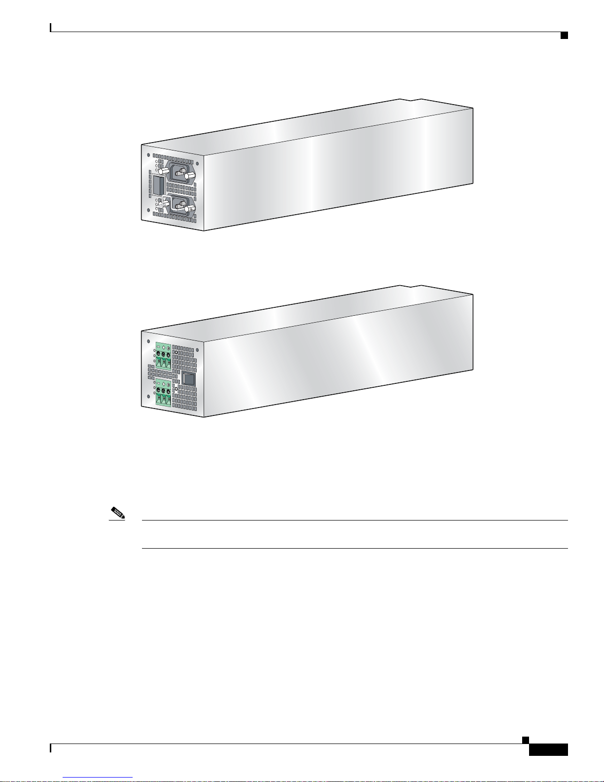
The Cisco 10720 Internet Router comes with either dual AC or dual DC power supplies for redundancy.
Figure 1-6 shows the AC power supply and Figure 1-7 shows the DC power supply for the Cisco 10720
Internet Router.
Cisco 10720 Internet Router Installation and Configuration Guide
1-6
78-13062-10
Page 33
Chapter 1 Product Overview
Figure 1-6 Cisco 10720 Internet Router AC Power Supply
AC OK
DC OK
Physical and Functional Overview
OTF
Fan Assembly
AC OK
DC OK
OTF
57673
Figure 1-7 Cisco 10720 Internet Router DC Power Supply
IN OK
DC
OTF
IN OK
DC
OTF
57674
The router is equipped with a four-fan assembly located on the inside of the back of the chassis. The fan
assembly offers redundancy; therefore, the router can continue to operate if one of the fans fails.
Note Replace the fan assembly when a failure occurs. (See the “Removing and Installing the Router Fan
Assembly” section on page 5-16.)
Mounts
The Cisco 10720 Internet Router can be mounted in the following ways:
• Front, mid-, or rear rack mounting in any of the following standard mounting bracket sizes:
–
19-inch EIA (Electronics Industry Association)
–
23/24-inch EIA
–
ETSI (European Telecommunications Standards Institute)
• Wall mounting
• Desk mounting
78-13062-10
Cisco 10720 Internet Router Installation and Configuration Guide
1-7
Page 34

Physical and Functional Overview
Cable Management
The cable-management system organizes the interface cables that lead into and away from the router.
Keep the interface cables out of the way of other cables and free of sharp bends.
The cable-management system consists of the following components:
• Cable-management tray for managing the cables
• Cable-management cover to keep the cables from being accidentally stressed
Software Features
A list of software features for the Cisco 10720 Internet Router follows. For more information about
advanced and other software features, refer to the Cisco
Internet Router publication.
• Cisco IOS Release 12.0 SP and Cisco IOS Release 12.0(29)S
• IP routing protocols, including Intermediate Standard- Intermediate System (IS-IS), Open Shortest
Path First (OSPF), Border Gateway Protocol-4 (BGP-4)
• Ethernet features
Chapter 1 Product Overview
IOS Software Configu ration for the Cisco 10720
–
Media dependent interface (MDI) and media dependent interface crossed (MDI-X) mode. (MDI
mode is supported on revision B of the combined Fast Ethernet and Gigabit Ethernet access
card, and in Japan on all access cards.)
–
10/100 speed auto-negotiation
–
Half-duplex/full-duplex (HDX-FDX) negotiation
–
Time Domain Reflectometry (TDR)
• Spatial Reuse Protocol (SRP) features
–
SRP intelligent protection switching (IPS)
–
IPS wrap-time < 50 ms
–
SRP rate-limiting for TX traffic (high/low-priority queue)
–
SRP priority slicing for TX traffic
–
SRP fairness algorithm (SRP-fa)
–
9,000 maximum transmission unit (MTU)
–
SRP hold-off timer for protected SONET
• Resilient Packet Ring (RPR) features
–
Intelligent Protection Switching (IPS): Steering mode or Wrapping mode
–
RPR Fairness: Per Station Fairness, weighted fairness, Conservative mode or aggressive mode
–
Topology: Advanced topology discovery combined with pro tection events
–
RPR classes: Support for classes A, B, and C in transit and Class A and B for transmit and
receive
–
RPR keepalive timer and L1 Holdoff timer
For the physical specifications of the Cisco 10720 Internet Router, see Appendix A, “Technical
Specifications.”
Cisco 10720 Internet Router Installation and Configuration Guide
1-8
78-13062-10
Page 35

Chapter 1 Product Overview
Design Specifications
The Cisco 10720 Internet Router includes the following design specifications:
• Network Equipment Building Systems, page 1-9
• Electromagnetic Compatibility, page 1-9
• Bonding and Grounding, page 1-9
• Environmental Monitoring, page 1-9
• Shock and Vibration, page 1-9
Network Equipment Building Systems
The Cisco 10720 Internet Router is built to comply with Network Equipment Building Systems (NEBS)
(Level 3 per SR-3580) in flammability, structural, and electronics compliance. For more information,
see the Regulatory Compliance and Safety Information for the Cisco 10720 document.
Design Specifications
Electromagnetic Compatibility
Electromagnetic Compatibility (EMC)—Emissions, Immunity, Electrostatic Discharge (ESD) for
product and packaging. For more information, see the
page 2-3 and the Regulatory Compliance and Safety Information for the Cisco 10720 document.
Bonding and Grounding
You should bond and ground the router for safety, circuit protection, noise currents, reliability, and
operations compliance. For more information, see the
section on page 3-9.
Environmental Monitoring
The Cisco 10720 Internet router provides envir onmental monitoring to assist the user in tracking router
operating temperature and humidity. Heat dissipation is not monitored.
Shock and Vibration
Shock and vibration tests are performed on the Cisco 10720 Internet Router. The router is tested to meet
the Corporate Mechanical Design Validation and T e st (MD VT) specification. Tests verify that the router
operating ranges meet handling and earthquake standards. This rout er was b uilt to comply with Net work
Equipment Building Systems (NEBS) (Zone 4 per GR-63-Core) in the following areas:
• Earthquake environment and criteria
• Office vibration and criteria
“Maintaining Safety with Electricity” section on
“Grounding the Cisco 10720 Internet Router”
• Transportation vibration and criteria
78-13062-10
Cisco 10720 Internet Router Installation and Configuration Guide
1-9
Page 36

Design Specifications
Chapter 1 Product Overview
Cisco 10720 Internet Router Installation and Configuration Guide
1-10
78-13062-10
Page 37

CHAPTER
Preparing for Installation
Installation preparation is presented in the following sections:
• Regulatory Compliance and Safety Information, page 2-1
• Warnings and Cautions, page 2-1
• Required Tools and Equipment, page 2-5
• Environmental Safety Guidelines, page 2-8
• Cisco IOS Software Configuration, page 2-11
• Required Tools and Equipment, page 2-5
• Verifying the Contents in the Box, page 2-11
• Site Log Preparation, page 2-12
Regulatory Compliance and Safety Information
2
See the Regulatory Compliance and Safety Information for th e Cisco 10720 Internet Router publication,
Document Number 78-13077-xx, for complete regulatory compliance and safety information. We
recommend you read and understand the safety warnings and guidelines before installing, configuring,
or maintaining the router.
Warnings and Cautions
The following sections concern warnings and cautions that accompany the Cisco 10720 Internet router:
• Safety Guidelines, page 2-2
• Maintaining Safety with El ectricity, page 2-3
• Electrostatic Discharge, page 2-3
• Laser Safety, page 2-4
• Ventilation Guidelines, page 2-5
78-13062-10
Cisco 10720 Internet Router Installation and Configuration Guide
2-1
Page 38

Warnings and Cautions
Safety Guidelines
Before you perform any procedures in this publication, review the safety guidelines in this section to
avoid injuring yourself or damaging the equipment.
The following guidelines will help to ensure your safety and protect the equipment. This list is not
inclusive of all potentially hazardous situations, so be alert.
Note Review the safety warnings listed in the Regulatory Compliance and Safety Information for the
Cisco 10720 Internet Router publication (Document Number 78-13077-xx) that accompanied your
Cisco 10720 Internet Router before installing, configuring, or maintaining the router.
Chapter 2 Preparing for Installation
Warning
Only trained and qualified personnel should be allowed to install or replace this equipment.
Statement 1030
• Never attempt to lift an object that might be too heavy for you to lift by yourself.
• Always disconnect the power sou rce and unplug all po wer cables before liftin g, moving, or w orking
on the router.
• Keep the work area clear and dust free during and after installation.
• Keep tools and router components away from walk areas.
• Do not wear loose clothing, jewelry (includ ing rings and chains), or other items that could get caught
in the router.
• Fasten your tie or scarf and sleeves.
• Use and operate the router in accordance with its electrical ratings and product usage instructions.
• Do not work alone if potentially hazardous conditions exist.
• Always unplug the power cables when performing maintenance or working on the router
Review the following safety compliance guidelines to avoid injuring yourself or damaging the
equipment:
• Your Cisco 10720 Internet Router should be installed in compliance with national and local
electrical codes: in the United States, National
States National Electrical Code; in Canada, Canadian
countries, International
• A Cisco 10720 Interne t Router configured with an AC-input power supply ships with a three-wire
Electrotechnical Commission (IEC) 364, part 1 through part 7.
Fire Protection Association (NFPA) 70, United
Electrical Code, part I, CSA C22.1; in other
electrical grounding-type plug that will only fit into a grounding-type power outlet. This is a safety
feature. The equipment grounding should be in accordance with local and national electrical codes.
• A Cisco 10720 Internet Router configured with a dual DC-input power supply requires an external
circuit breaker for the DC-input power source. This circuit breaker should protect against
short-circuit and overcurrent faults in accordance with United States National Electrical Code NFP A
70 (United States), Canadian Electrical Code, part I, CSA C22.1 (Canada), or IEC 364 (other
countries).
• A Cisco 10720 Interne t Router configured with an AC-input power supply must have the
socket-outlet combination installed near the router, and it must be easily accessible at all times. The
socket-outlet combination serves as the main disconnecting device.
• A Cisco 10720 Interne t Router configured with a DC-input power supply must have a readily
accessible disconnect device incorporated in the fixed wiring.
Cisco 10720 Internet Router Installation and Configuration Guide
2-2
78-13062-10
Page 39

Chapter 2 Preparing for Installation
Maintaining Safety with Electricity
For information on maintaining safety with electricity, see the “Safety Guidelines” section on page 2-2.
Electrostatic Discharge
Electrostatic discharge (ESD) can damage circuit boards if they are handled improperly. Such
mishandling can result in intermittent or complete failures of the board.
When handling circuit boards, observe the following guidelines to prevent ESD damage:
• Always use an antistatic wrist strap and ensure that the strap makes adequate contact with your skin.
• Attach an ESD-preventive strap to your wrist, and to the chassis or to a bare metal surface. (See
Figure 2-1.)
• The wrist strap protects equipment from ESD voltages on the body only; ESD voltages on clothing
can still cause damage to electronic components.
Caution For safety, periodically check the resistance value of the ESD-preventive wrist strap. The resistance
measurement should be between 1 and 10 megohms (Mohms).
Warnings and Cautions
Preventing Electrostatic Discharge
Electrostatic discharge (ESD) damage can occur when electronic cards or components are improperly
handled. ESD can cause complete or intermittent failures. We recommend using an antistatic strap when
you handle a router or one of its components.
Electromagnetic interference (EMI) shielding is an integral component of the router.
Following are guidelines for preventing ESD damage:
• Always use an ESD-preventive wrist or ankle strap and ensure that it makes good skin contact.
Connect the equipment end of the connection cord to bare metal on the router chassis. (See
Figure 2-1.)
Figure 2-1 Attaching an ESD-Preventive Strap
U
R
E
R
IE
T
H
IV
R
K
T
P
T
R
P
C
A
S
A
X
A
S
R
C
R
A
W
P
R
ESE
T
S
U
C
A
P
O
NS
T
M
IL
O
LE
A
E
S
A
C
O
A
T
K
U
M
F
X
R
R
E
D
E
E
T
R
V
S
W
A
O
Y
O
C
D
C
S
O
P
K
O
T
F
IL
A
)
F
S
G
(
P
D
B
E
R
V
M
A
I
C
0
T
0
C
1
A
/
K
IN
L
IL
A
F
R
D
E
R
W
A
O
A
C
C
O
P
K
D
C
O
K
O
T
F
D
O
N
N
O
T
R
E
M
O
O
V
R
E
IN
S
ER
T
C
A
B
W
LE
ITH
S
TH
E PO
W
E
R
O
N
IN
P
U
T
1
0
0
-2
0
0
- 5
0
/6
0
H
z
2
-5
A
57849
78-13062-10
Cisco 10720 Internet Router Installation and Configuration Guide
2-3
Page 40

Warnings and Cautions
Laser Safety
Chapter 2 Preparing for Installation
• When installing an uplink or access card, confirm that the card is fully seated in the midplane and
tighten the spring-loaded screws. These screws prevent accidental removal, provide proper
grounding for the system, and help ensure that the connectors are seated in the midplane.
See the “Removing and Installing an Uplink Card” section on page 5-49 and “Removing and
Installing an Access Card” section on page 5-58.
• When removing an uplink or access card, use the spring-loaded screws to unseat the ca rd co nnecto r
from the midplane.
See the “Removing and Installing an Uplink Card” section on page 5-49 and “Removing and
Installing an Access Card” section on page 5-58.
• Handle cards by the spring-loaded screws only; avoid touching the board or connector pins.
• Place a removed card board-side-up on an antistatic surface or in a static shielding bag. If you plan
to return the component to the factory, immediately place it in a static shielding bag.
• Avoid contact between the card and clothing. The wrist strap protects the board only from ESD
voltages on the body; ESD voltages on clothing can still cause damage.
The uplink card is equipped with a Class 1 laser that emits invisible radiation. Do not stare into open line
card ports. The following laser warnings apply to the Cisco
Class 1 Laser Product Warning
Warning
Class 1 laser product.
General Laser Warning
Warning
Avoid exposure to laser radiation. Do not stare into an open aperture, because invisible laser
radiation may be emitted from the aperture when a cable is not inserted in the port.
For translated Class 1 laser warnings, refer to the Re gulatory Compl iance and Safety Information for the
Cisco 10720 Internet Router publication.
Class 1 LED Product Warning
Warning
Class 1 LED product.
10720 Internet Router:
Statement 1008
Statement 125
Statement 1027
Cisco 10720 Internet Router Installation and Configuration Guide
2-4
78-13062-10
Page 41

Chapter 2 Preparing for Installation
Required Tools and Equipment
The following tools and equipment are required to install the Cisco 10720 Internet Router:
• ESD-preventive wrist strap
• Number 1 Phillips screwdriver
• 1/8-inch flat-blade screwdriver
• Antistatic mat (optional)
• Antistatic bag
• Cable ties
• Wire stripper
Rack-Mounting Guidelines
Before installing the Cisco 10720 Internet Router in a 19-inch EIA, 23- or 24-inch EIA, or ETSI
equipment rack, consider the general rack-mounting guidelines presented in the following sections:
Required Tools and Equipment
• Ventilation Guidelines, page 2-5
• Rack-Mounting Clearance Guidelines, page 2-6
• Maintenance Guidelines for Multiple Routers in a Rack, page 2-6
Ventilation Guidelines
Caution The fan assembly is located in the back of the router chassis. Air flow in the front and back of the
router should not be blocked.
Use these guidelines to provide adequate ventilation for the Cisco 10720 Internet Router:
• Install the chassis in an enclosed rack only if the rack has adequate ventilation or an exhaust fan; use
an open rack when possible.
• A ventilation system that is too powerful in an enclosed rack can also prevent cooling by creating
negative air pressure around the router and redirecting the air away from the air intake vent. If
necessary, operate the router with the rack door open or in an open rack.
• Make sure that the air baffle located b et ween th e fan assembly and power supply is properly seated
to assist in cooling the router.
• Check equipment located near the bottom of the rack, because it can generate excessive heat that is
drawn upward and into the intake ports of equipment above, possibly leading to overheating.
78-13062-10
Cisco 10720 Internet Router Installation and Configuration Guide
2-5
Page 42

Rack-Mounting Guidelines
Rack-Mounting Clearance Guidelines
The rack-mounting hardware included with the Cisco 10720 Internet Router is suitable for most 19-inch
EIA, 23- or 24-inch EIA, or ETSI equipment racks or Telco-style racks.
The following are rack-mounting guidelines for the Cisco 10720 Internet Router:
• If you use a T elco-st yle rack, be sure that the rack is bolted to the floor, the router mounts to the two
rack posts, and the rest of the router is cantilevered off the posts.
• Some Telco-style racks are secured to ceiling brackets, if necessary, because of the weight of the
equipment in the rack. Make sure that the rack on which yo u are instal ling the Cisco
Internet
Note W a rm air e xhausts out the back sid e of the router b y dr a wing cool air in through v en ts located on the
front of the router chassis. Allow sufficient airflow by maintainin g 6 inches (15.24 cm) of clearance
at both the inlet and exhaust openin gs on t he rout er and 0.75 inch ( 1.9 cm) on each sid e of the rout er
chassis.
Router is secured.
Chapter 2 Preparing for Installation
10720
Maintenance Guidelines for Multiple Routers in a Rack
The Cisco 10720 Internet Router is 17.50 inches (44.45 cm) wide by 3.45 inches (8.76 cm) high by
18.25 inches (46.36 cm) deep. The height is equivalent to two rack units (RU). The router is 21.80 inches
(55.37 cm) deep when the cable-management tray is installed. When placing multiple routers in a rack,
ensure that there is sufficient ventilation to accommodate the routers.
The heated exhaust air from other equipment can enter the inlet air vents and cause overheating inside
the router. To avoid this, follow these guidelines:
• Install and use the cable-management system included with the router to keep cables organized and
out of the way of the cards and power supply.
• Ensure that cables from other equipment do not interfere with access to the cards and LEDs located
in the front of the router.
• When mounting the router in a rack, be sure to use all the screws provided to secure the router to the
rack posts.
Cisco 10720 Internet Router Installation and Configuration Guide
2-6
78-13062-10
Page 43

Chapter 2 Preparing for Installation
Figure 2-2 Cisco 10720 Internet Router Outer Dimensions (Top View)
Rack-Mounting Guidelines
17.50 in.
(44.45 cm)
18.25 in.
(46.36 cm)
Chassis
21.80 in.
(55.37 cm)
Cable management bracket
57878
Height = 2 RU
78-13062-10
Cisco 10720 Internet Router Installation and Configuration Guide
2-7
Page 44

Environmental Safety Guidelines
Environmental Safety Guidelines
This section offers guidelines for operating your Cisco 10720 Internet Router in various environments:
• Airflow Guidelines, page 2-8
• Temperature and Humidity Guidelines, page 2-8
• Power Guidelines, page 2-9
• Site Wiring Distance and Interference Guidelines, page 2-10
• Cable Management, page 2-11
• Mounting the Router, page 2-11
Airflow Guidelines
The Cisco 10720 Internet Router air circulation system consists of four fans installed in the back of the
router chassis. The fan assembly maintains acceptable operating temperatures for the internal
components by drawing cooling air in through vent s located on the front of the rout er chassis, circulating
the air through the router, and exhausting the air out of the back of the router chassis.
Observe the following guidelines when selecting a site at which to install the Cisco 10720
Internet
Router:
Chapter 2 Preparing for Installation
Note W a rm air e xhausts out the back sid e of the router b y dr a wing cool air in through v en ts located on the
front of the router chassis. Allow sufficient air flow by maintaining 6 inches (15.24 cm) of cl earance
at both the inlet and exhaust open ings on the router and 0.75 inch ( 19.1 mm) on each side of the router
chassis.
• The site should be as dust-free as possible.
• Under extreme environment conditions, the environmental monitoring system will shut down the
power to protect the system components.
Temperature and Humidity Guidelines
The operating environmental site requirements are located in Appendix A, “Technical Specifications.”
The temperature and humidity ranges listed are those within which the router will continue to operate.
You can maintain normal operation by anticipating and correcting environmental irregularities before
they approach critical values.
The environmental monitoring fun ctionality b uilt in to the router protects the system and its components
from potential damage from overvoltage and overtemperature conditions.
T o assure normal operation an d av oid maintenance dif ficulty, plan and prepare your site before installing
the router.
Cisco 10720 Internet Router Installation and Configuration Guide
2-8
78-13062-10
Page 45
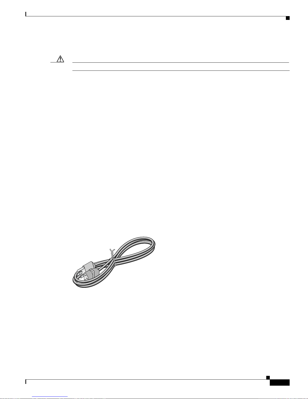
Chapter 2 Preparing for Installation
Power Guidelines
Caution Read the installation instructions before you connect the router to its power source.
The Cisco 10720 Internet Router requires a 120/220 VAC or –48 VDC dual power supply. Site
requirements differ depending on the type of source voltage. We recommend you follow these
precautions and recommendations when planning power connections to your router:
• Check the power at your site before installation and periodi cally after installation to en sure that you
are receiving clean power. Install a power conditioner if necessary.
• Install proper grounding, or use the proper grounding receptacle to av oid damage from lightning and
power surges.
• Read the safety warnings before you connect the AC or DC power supply to the electrical power at
the local or remote site.
AC-Powered Router
Environmental Safety Guidelines
The AC dual power supply includes two terminal blocks for power redundancy. (See Figure 1-6.) The
grounding screw is located in the terminal block.
The following guidelines will help to ensure your safety and protect the equipment. This list does not
include every potentially hazardous situation, so be alert.
• Install an uninterruptable power source where possible.
• Install proper grounding to avoid damage from lightning and power surges.
See the “Safety Guidelines” section on page 2-2 for additional information. See Figure 2-3 for an
example of a typical AC power cord.
Figure 2-3 AC Power Cord
57977
DC-Powered Router
The DC dual power supply includes two terminal blocks for power redundancy. (See Figure 1-7.)
The minimum wire gauge size supported on the DC dual power supply is 17 American Wire Gauge
(AWG), which has a 1.5mm wire diameter. The maximum wire gauge size supported on the DC dual
power supply is 10 AWG, which has a 6mm wire diameter.
Wires that are installed in the router power source come from two other external DC power sources. If
the DC power source on Bus B fails, Bus A will continue to power the generator.
78-13062-10
Cisco 10720 Internet Router Installation and Configuration Guide
2-9
Page 46

Environmental Safety Guidelines
The following guidelines wi ll help to ensure saf ety and prot ect the equipment. This list does not include
every potentially hazardous situation, so be alert.
A Cisco 10720 Interne t Router configured with the dual DC-input power supply should have a readily
accessible disconnect device incorporated for fixed wiring.
See the “Safety Guidelines” section on page 2-2 for additional information.
Caution F or safety, periodically check the resistance valu e of the antistatic strap. The measurement should be
between 1 and 10 megohms (Mohms).
Chapter 2 Preparing for Installation
Warning
A readily accessible two-pole disconnect device must be incorporated in the fixed wiring.
Statement 91
Site Wiring Distance and Interference Guidelines
This section offers site wiring guidelines fo r setting up the sit e plant wiring and cabling. When planning
the location of the new system, consider the following:
• Electromagnetic Interference, page 2-10
• Distance Limitations for Signaling and Unshielded Conductors, page 2-10
Electromagnetic Interference
Electromagnetic interference (EMI) can occur between the field and the signals on the wires when the
wires are run for any significant distance. This fact has two implications for the construction of plant
wiring:
• Poor wiring practice can result in radio interference emanating from the plant wiring.
• Strong EMI, especially when it is caused by lightning or radio t ransmitters, can destroy and/or cause
interference with the signal drivers and recei vers in the router , and can create an electrical hazard by
conducting power surges through lines and into equipment.
Note T o predict and remedy strong EMI, consult experts in radio frequency interference (RFI).
A good quality twisted pair cable or shielded twisted pair cable helps limit radiation and noise induced
into the cable, minimizing the potential for the following:
• Radio interference
• Interference with the data transmission
Distance Limitations for Signaling and Unshielded Conductors
You must give special consideration to the effect of a lightning strike in the site vicinity if wires exceed
recommended distances, or if wires pass between buildings. The electromagnetic pulse (EMP) caused
by lightning or other high-energy phenomena ca n easily couple enough energy into unshielded
conductors to destroy electronic devices.
Cisco 10720 Internet Router Installation and Configuration Guide
2-10
78-13062-10
Page 47

Chapter 2 Preparing for Installation
You must provide a properly grounded and shielded environment. Consider electrical surge suppression
issues by addressing the following items:
• Potential surge sources
• Distance
Caution Splicing can degrade cable performance.
Cable Management
The cable-management system, located on the front of the router, organizes the interface cables. The
cable-management system consists of the following components:
• Cable-management tray for managing cables
• Cable-management cover to keep cables from being accidentally stressed
Before mounting the router or connecting the ports on an uplink card or access card, install the
cable-management tray. For more information, see the
section on page 5-70.
Cisco IOS Software Configuration
“Installing the Cable-Management System”
Mounting the Router
Rack mount brackets are available for 19-inch EIA, 23-inch EIA, or 24-inch EIA, and ETSI racks.
Wall-mount brackets and desktop mounts are also available options. For more information about
mounting the Cisco
10720 Internet Router, see the “Rack-Mounting the Router” section on page 3-2.
Cisco IOS Software Configuration
The Cisco IOS software that runs on your router contains extensive features and functionality.
For Cisco IOS software configuration informatio n and su pport, refer to t he configuration and command
reference publications in the Cisco
Cisco
IOS software release installed on your Cisco hardware. You can also refer to the Cisco IOS
software release notes for the version of Cisco
For a list of these documents, see “Related Documentation” section on page xix.
IOS software configuration documentation set that corresponds to the
Verifying the Contents in the Box
Check the contents of the shipping packaging and verify that the following are included with your
shipment:
• One Cisco 10720 Internet Router fully assembled that includes the following:
–
1 uplink card
–
1 access card
IOS software you are using on your router.
–
1 AC or DC dual power supply
–
1 main board
78-13062-10
Cisco 10720 Internet Router Installation and Configuration Guide
2-11
Page 48

Site Log Preparation
–
1 midplane board
–
1 fan assembly containing 4 fans
–
1 air baffle located between power supply and fan number 4
• One accessory kit that includes the following:
–
19-inch EIA rack-mount brackets (quantity 2)
–
23- to 24-inch EIA rack-mount brackets (quantity 2)
–
ETSI rack-mount brackets (quantity 2)
–
Wall-mount brackets (quantity 2)
–
Rubber foot pads for desk mounting (quantity 4)
–
Cable-management system (quantity 1 cable-management tray and 1 cable-management cover)
–
AC power cable (quantity 2)
–
Metal AC bracket clips (quantity 2)
–
Screws (quantity 22)
–
Ground lug (quantity 1)
Chapter 2 Preparing for Installation
–
Lug-mounting 6.3 mm (M5) screws (quantity 2)
• Cisco 10720 Internet Router Unpacking Instructions
• Regulatory Compliance and Safety Information for the Cisco 10720 Internet Router
• Obtaining Documentation for the Cisco 10720 Internet Router
If you do not receive everything you ordered, contact a customer service representative for assistance.
Site Log Preparation
Table 2-1 shows a sample site log. Make copies of the sample or design your own site log. The site log
lets you record operation and main tenance ac tivity. Keep the site log in an accessible place near the
router.
Site log entries might include the following:
• Installation progress—Make entries in the site log to record installation progress. Log any
difficulties encountered and remedies during the installation process for future reference.
• Upgrades and remov al/replacement procedures—Use th e site log as a record of system maintenance
and expansion history.
Each time a procedure is performed on the system, update the site log to record the following:
• Field-replaceable hardware installed, removed, or replaced
• Router configuration changes
• Software upgrades
• Corrective or preventive maintenance procedures performed
• Intermittent problems
• Your comments
Cisco 10720 Internet Router Installation and Configuration Guide
2-12
78-13062-10
Page 49

Chapter 2 Preparing for Installation
Tab le 2-1 Site Log for the Cisco 10720 Inter net Router
Device Identification:
Date Description of Action Performed or Symptom Observed Initials
Site Log Preparation
78-13062-10
Cisco 10720 Internet Router Installation and Configuration Guide
2-13
Page 50

Site Log Preparation
Chapter 2 Preparing for Installation
Cisco 10720 Internet Router Installation and Configuration Guide
2-14
78-13062-10
Page 51

CHAPTER
3
Installing the Cisco 10720 Internet Router
Instructions for installing the Cisco 10720 Internet Router and its basic components are presented in the
following sections:
• Setting up the Cisco 10720 Internet Router, page 3-1
• Grounding the Cisco 10720 Internet Router, page 3-9
• SONET Distance Limitations, page 3-11
• Connecting Ports on the Uplink Cards, page 3-12
• Creating a Four-Node DPT Ring, page 3-14
• Creating a Four-Node IEEE 802.17 RPR Mode Ring , page 3-17
• Connecting Ethernet Ports on the Access Card, page 3-22
• Installing the Cable-Management Syste m, page 3-2 5
• Turning On Power to the Router, page 3-26
• Verifying the Router Power Is Turned On, page 3-32
• Initial Setup Configuration, page 3-32
• Verifying the Cisco 10720 Internet Router LEDs, page 3-33
• Additional Configuration Features, page 3-42
Setting up the Cisco 10720 Internet Router
Verify the following before you install the router:
• Fan assembly exhaust vents are not blocked.
• The front of the router is not blocked. The airflow intake is located on the front of the router.
• 24 inches (61 cm) of clearance in front of the router may be needed for working with line cards,
power supplies, attaching network interface cards (NICs), or other components.
• Location is temperature-controlled, air-conditioned, and dust-free.
• Power cables and power supplies have been checked for compatibility with your power service.
• Labels on the equipment have been checked to ensure that the power service at your site is suitable
for the router.
• AC- or DC-power source voltage receptacles are easy to reach.
Cisco 10720 Internet Router Installation and Configuration Guide
78-13062-10
3-1
Page 52

Setting up the Cisco 10720 Internet Router
Note For information about environmental considerations and requirements, see the “Environmental
Safety Guidelines” section on page 2-8.
Cable Management
Install the cable-management tray, which is part of the cable-managemen t system, onto the router before
mounting the router on a rack, wall, or desktop. For instructions on installing the cable-management
system, see the
“Removing and Installing the Cable-Management System” section on page 5-68.
Rack-Mounting the Router
This section describes how to mount the router on an equipment rack, wall , or desktop. The router co mes
with three sets of brackets for rack-mounting, one set of brackets for wall-mo unting, and four rubber foot
pads for desk-mounting.
Check the clearance around the router before you install the router. See the “Required Tools and
Equipment” section on page 2-5 for detailed dimension requirements.
Chapter 3 Installing the Cisco 10720 Internet Router
Cisco 10720 Internet Router Installation and Configuration Guide
3-2
78-13062-10
Page 53

Chapter 3 Installing the Cisco 10720 Internet Router
Figure 3-1 Ventilation Requirements for Rack Mounting
Setting up the Cisco 10720 Internet Router
6 in.
(15.24 cm)
0.75 in.
(1.9 cm)
0.75 in.
(1.9 cm)
6 in.
(15.24 cm)
57879
Note W arm air exhausts out the back end of the router by drawing cool air in throu gh vents located on the front
of the router chassis. Allow sufficient airflow by maintaining 6 inches (15.24 cm) of clearance at both
the inlet and exhaust openings on the router and 0.75 inch (19.1 mm) on each side of the router chassis.
(See Figure 3-1.)
78-13062-10
Cisco 10720 Internet Router Installation and Configuration Guide
3-3
Page 54

Setting up the Cisco 10720 Internet Router
The following steps describe ho w to mount the router on a 19-inch EIA, 23-inch, or 24-inch EIA , or ETSI
rack:
Figure 3-2 Rack-Mounting Brackets
ETSI
Chapter 3 Installing the Cisco 10720 Internet Router
19 inch
23/24 inch
57664
Step 1 Choose the appropriate rack-mounting brackets to fit your rack. (See Figure 3-2.)
Step 2 Attach an ESD-preventive wrist strap to your wrist, and to the router chassis or to a bare metal surface.
(See the
“Preventing Electrostatic Discharge” section on page 2-3.)
Step 3 Turn the router so that the front panel is facing you. The fans are in the back of the router.
Cisco 10720 Internet Router Installation and Configuration Guide
3-4
78-13062-10
Page 55

Chapter 3 Installing the Cisco 10720 Internet Router
Figure 3-3 Installing Rack Mounting Brackets
U
R
E
R
E
I
T
H
IV
R
K
T
P
T
R
P
C
A
S
A
X
A
S
R
C
R
A
W
P
U
R
E
R
E
I
T
H
IV
R
K
T
P
T
R
P
C
A
S
A
X
A
S
R
C
R
A
W
P
Setting up the Cisco 10720 Internet Router
R
E
S
E
T
S
U
C
A
P
O
NS
T
L
M
I
OL
S
AC O
E
E
A
A
T
F
K
U
M
X
R
R
E
D
E
E
T
R
V
S
W
A
O
Y
O
C
DC OK
S
P
OTF
L
I
A
)
F
S
G
(
P
D
B
E
R
V
M
A
I
C
0
T
0
C
1
A
/
K
N
I
L
IL
A
F
R
D
E
R
W
A
O
AC OK
C
P
DC O
K
OTF
D
O
N
N
O
T
R
E
M
O
O
V
R
E
I
N
S
E
R
T
C
A
W
B
L
IT
E
H
S
T
H
E
P
O
W
E
R
O
N
INP
UT 100-200- 50/60Hz 2-5A
19 inch
R
E
S
ET
S
U
C
A
P
O
N
T
S
M
IL
O
L
AC O
E
E
S
A
A
T
F
K
U
M
X
R
R
E
D
E
E
T
R
V
S
W
A
O
Y
O
C
DC OK
S
P
OTF
L
I
A
)
F
S
G
(
P
D
B
E
R
V
M
A
I
C
0
T
0
C
1
A
/
K
N
I
L
L
I
A
F
R
D
E
R
W
A
O
AC OK
C
P
DC OK
OTF
D
O
N
N
O
T
R
E
M
O
O
V
R
E
IN
S
E
R
T
C
A
W
B
L
IT
E
H
S
T
H
E
P
O
W
E
R
O
N
INPUT 100-200- 50/60Hz 2-5A
ETSI
U
R
E
R
E
I
T
H
IV
R
K
T
T
P
R
P
C
A
S
A
X
A
S
R
C
R
A
W
P
R
ES
E
T
S
U
C
A
P
O
N
T
S
M
IL
O
L
S
AC OK
E
E
A
A
T
F
U
M
X
R
R
E
D
E
E
T
R
V
S
W
A
O
Y
O
C
DC OK
S
P
OTF
L
I
A
)
F
S
G
(
P
D
B
E
R
V
M
A
I
C
0
T
0
C
1
A
/
K
N
I
L
L
I
A
F
R
D
E
R
W
A
O
AC OK
C
P
DC OK
OTF
D
O
N
N
O
T
R
E
M
O
O
V
R
E
IN
S
E
R
T
C
A
W
B
L
IT
E
H
S
T
H
E
P
O
W
E
R
O
N
INPUT 100-200- 50/60Hz 2-5A
57751
23/24 inch
Step 4 Align the brackets to the right and left sides of the router. Use the Number 1 Phillips screwdriver with
the screws that are supplied in the accessory kit to attach the brackets to the router. (See
Figure 3-3.)
Step 5 Install the router in a rack with the front panel forward.
Figure 3-4 Attaching the Router to the 19-Inch Rack (Front Panel Forward)
ACTIVE
CARRIER
RX PKT
WRAP
PASS THRU
R
E
S
E
T
C
O
N
S
O
L
AC O
E
A
K
U
X
OVERTEMP
CARD FAIL
DC OK
SYSTEM STAUS
POWER
O
TF
L
I
A
)
F
S
G
(
P
D
B
E
R
V
M
A
I
C
0
T
0
C
1
A
/
K
N
I
L
AC O
CARD FAIL
POWER
K
DC O
K
OTF
DON NOT REMOVE
OR INSERT CABLES
WITH THE POWER ON
INPUT 100-200- 50/60Hz 2-5A
57665
Step 6 Align the mounting brackets on the router with the holes in the rack.
78-13062-10
Cisco 10720 Internet Router Installation and Configuration Guide
3-5
Page 56

Setting up the Cisco 10720 Internet Router
Use a Number 1 Phillips screwdriver to attach the four screws that are supplied in the cable accessory
kit to attach each side of the router chassis to the rack. (See
Wall-Mounting the Router
The wall-mounting brackets must be mounted on a minimum 5/8-inch (15.9 mm) gypsum wallboard or
equivalent with 12 1-1/4-inch Number 10 screws or equivalent (M5 x 31.8 mm).
Caution The front and back panels of the router require at least 6 inches of clearance away from the wall or
other items that can block the airflow . The side panel requires 1 inch of clearance away from the wall
or other items that can block the airflow. The top and bottom of the router chassis do not require any
specific clearance.
Perform the following steps to set up a proper and secure wall mount for the router. These steps ensure
that adequate ventilation is a vailable at al l times. A Number 1 Phillips scre wdri ver is required to perform
the following procedure:
Chapter 3 Installing the Cisco 10720 Internet Router
Figure 3-4.)
Step 1 Locate the two 17.25-inch (43.82 cm) long metal mounts, 12 1-1/4-inch Number 10 (3.18 cm) screws,
and 10 screws for attaching the mount to the router chassis, included in the accessories kit.
Note Verify that no electrical, heating, or plumbing apparatus is located behind the drilling location.
Figure 3-5 Predrilled Holes on a Mounting Surface
3.23 in.
(8.2 cm)
57851
18.35 in.
(46.6 cm)
Step 2 Predrill 12 holes on the mounting surface. The holes on the side of the router chassis are 3.23 inch es (8.2
cm) apart. The side-to-side distance is 18.35 inches (46.6 cm). (See
Cisco 10720 Internet Router Installation and Configuration Guide
3-6
Figure 3-5.)
78-13062-10
Page 57
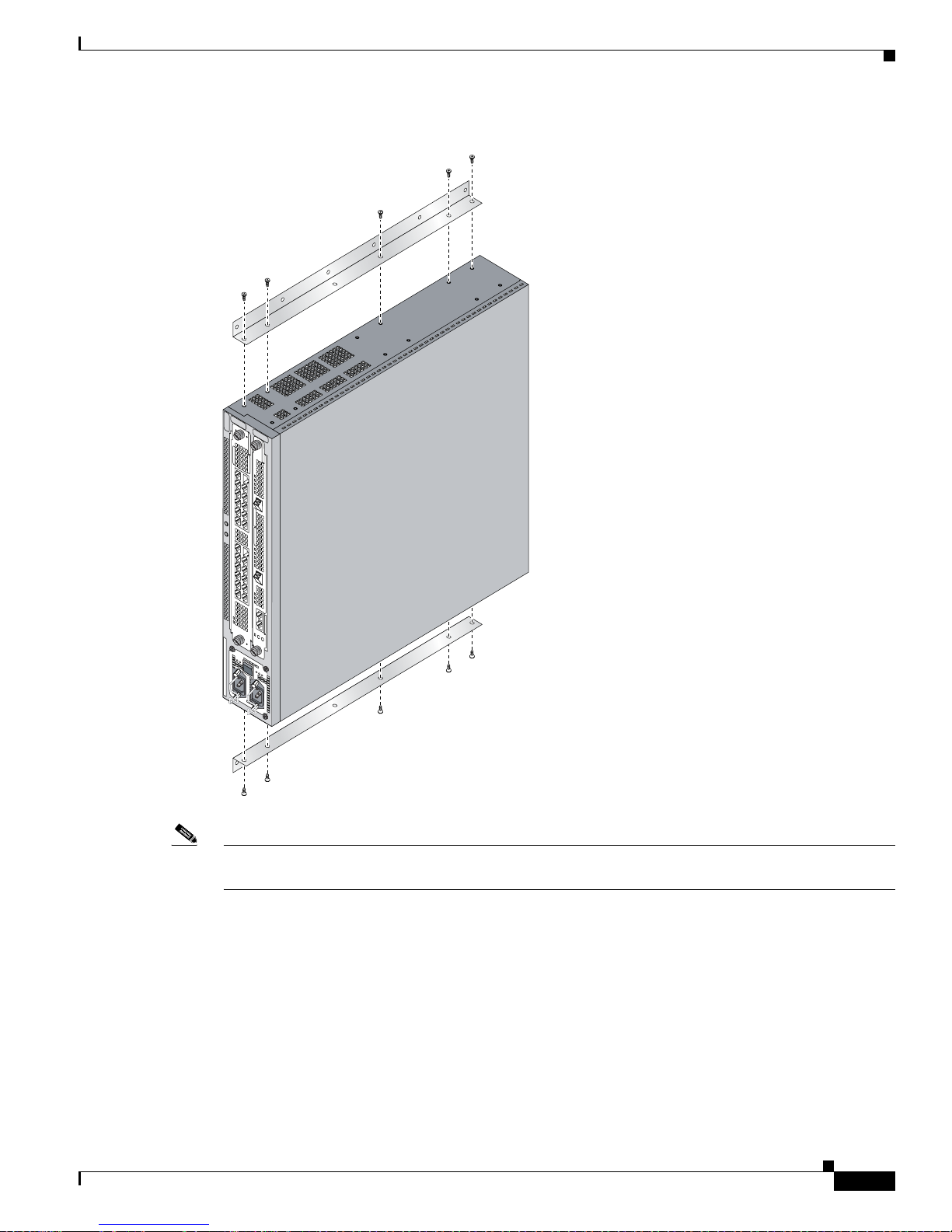
Chapter 3 Installing the Cisco 10720 Internet Router
Figure 3-6 Attaching Wall-Mounting Brackets to the Router Chassis
Setting up the Cisco 10720 Internet Router
57853
O
T
IN
F
D
O
C
K
O
T
IN
F
D
O
C
K
Note When the rack is mounted on the wall, make sure that the power receptacles are at the bottom of the
router, as shown in Figure 3-6.
Step 3 Attach an ESD-preventive strap to your wrist, and to the router chassis or to a bare metal surface. (See
the
“Preventing Electrostatic Discharge” section on page 2-3.)
Step 4 Attach the wall-mounting brackets to the side of each chassis using five screws on each side. (See
Figure 3-6.)
78-13062-10
Cisco 10720 Internet Router Installation and Configuration Guide
3-7
Page 58

Setting up the Cisco 10720 Internet Router
Figure 3-7 Wall-Mount Rack
Chapter 3 Installing the Cisco 10720 Internet Router
O
T
IN
F
D
O
C
K
O
T
IN
F
D
O
C
K
Step 5 Match the holes in the wall-mounting brackets to the predrilled holes on the mounting surface. Mount
the brackets to the wall using the 12 1-1/4-inch screws. (See
Setting up the Router on a Desktop
Use the four rubber feet included with the accessory kit to prepare the Cisco 10720 Internet Router for
desktop setup. To set up the router on a desktop, perform the following steps:
Step 1 Locate the rubber feet that came with the router.
Step 2 Attach an ESD-preventive wrist strap to your wrist, and to the router chassis or to a bare metal surface.
(See the
Step 3 Turn the router upside down to expose the bottom panel.
“Preventing Electrostatic Discharge” section on page 2-3 for additional information.)
57666
Figure 3-7.)
Cisco 10720 Internet Router Installation and Configuration Guide
3-8
78-13062-10
Page 59

Chapter 3 Installing the Cisco 10720 Internet Router
Figure 3-8 Applying Rubber Feet to the Bottom of the Router Chassis
Step 4 Pull the adhesive paper off the rubber feet and apply them to the bottom of the router. (See Figure 3-8.)
Caution The front and back panels of the router require at least 6 inches clearance a way from the w all or other
items that can block proper airflow. The side panel requires 1 inch of clearance away from the wall
or other items that can block proper airflow. The top and bottom of the router chassis do not require
any specific clearance.
Grounding the Cisco 10720 Internet Router
57854
Step 5 Turn the router over and set it on a desktop or other level surface that provides the necessary ventilation
clearance.
Grounding the Cisco 10720 Internet Router
If the router is installed in a Network Equipment Building System (NEBS) environment, follow the
guidelines in this section. For installation s other than i n a NEBS environment, you may chose to rely on
the safety earth ground connection supplied via the International Electrotechnical Commission
(IEC)
320 plugs for the AC power supply and DC power supply.
For additional NEBS information, see the Regulatory Compliance and Safety Information for the Cisco
10720 document.
Supplemental Unit Bonding and Grounding Guidelines
If the router is not installed in a NEBS environment, you can bypass these guidelines and rely on the
safety earth ground connection supplied via the IEC
supply.
Bonding and grounding receptacles are intended to satisfy the Telcordia NEBS requirements for
supplemental bonding and grounding connections. The router requires a safety earth ground connection
as part of the power cabling to the AC and DC power supplies.
We strongly recommend that you connect the central office (CO) ground system or interior equipment
grounding system to the chassis. Grounding to the CO system or your interior equipment grounding
system meets the NEBS bonding and grounding requirement.
320 plugs for the AC power supply and DC power
78-13062-10
Cisco 10720 Internet Router Installation and Configuration Guide
3-9
Page 60
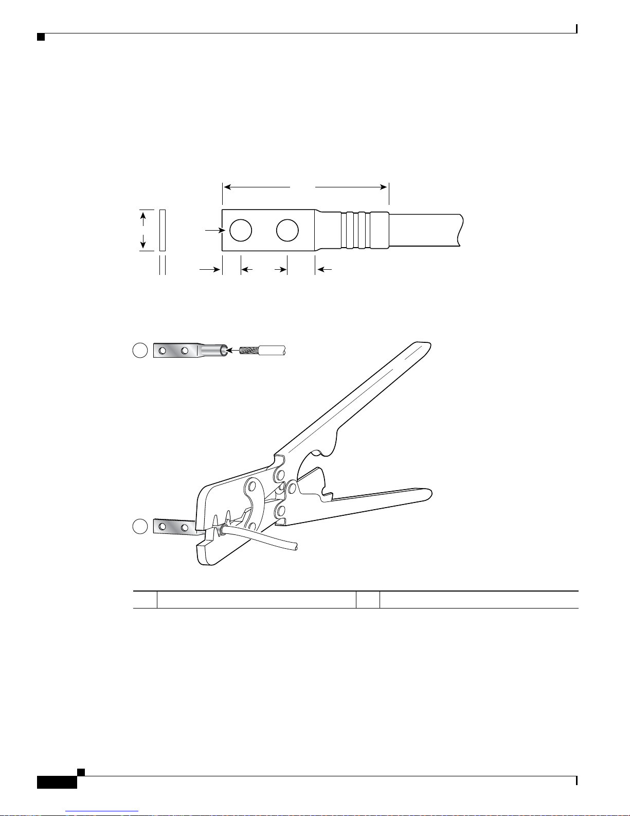
Grounding the Cisco 10720 Internet Router
Use a dual-hole cable lug to attach it to the chassis. Use two 6.3 mm (M6) screws on the 0.63-inch (16
mm) centers as shown in
(Part Number 32-0607-01). Grounding con nectors shall be NRTL listed; use copper conductors only for
grounding and bonding connectors.
Figure 3-9 Cable Lug
End View
Chapter 3 Installing the Cisco 10720 Internet Router
Figure 3-9, Figure 3-10, and Figure 3-11. The lug can be ordered from Cisco
All measurements in inches
2.24
0.48
Figure 3-10 Crimping the Lug
Ø 0.267
2 holes
0.25 0.370.63
0.08
1
2
Crimp area
25527
57808
1 Place ground wire in the lug 2 Crimp the lug
Cisco 10720 Internet Router Installation and Configuration Guide
3-10
78-13062-10
Page 61
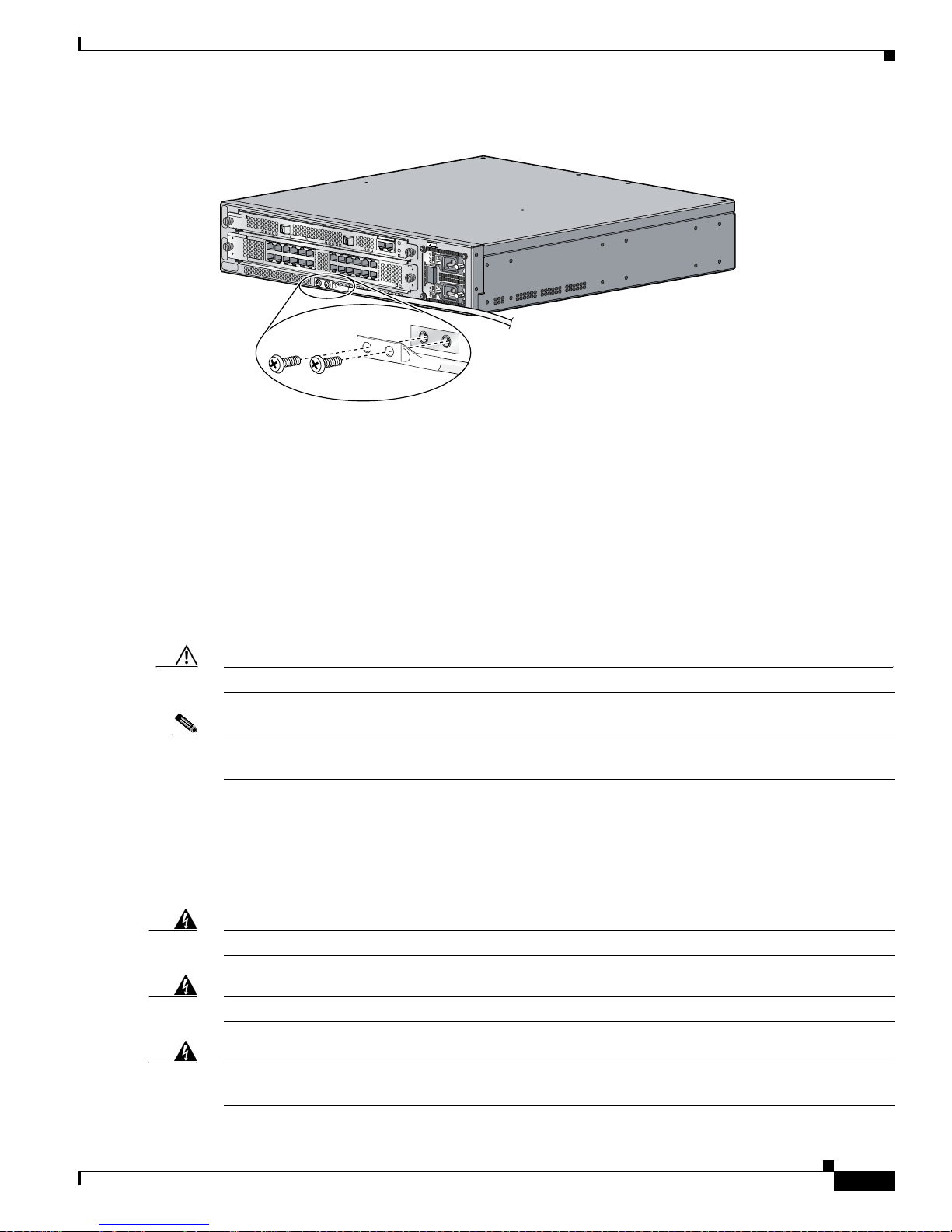
Chapter 3 Installing the Cisco 10720 Internet Router
Figure 3-11 Attaching the Grounding Lug to the Router Chassis
U
R
E
R
IE
T
H
IV
R
K
T
P
T
R
P
C
A
S
A
X
A
S
R
C
R
A
W
P
RESET
S
U
CONSO
A
P
T
M
IL
LE
AC OK
E
S
A
AUX
T
M
F
R
R
E
D
E
E
T
R
V
S
W
A
O
Y
O
C
DC OK
S
P
OTF
AIL
)
S
F
P
(G
D
B
E
M
AR
IV
C
0
T
C
10
/A
K
IN
L
IL
A
F
R
D
E
R
W
A
O
AC OK
C
P
DC OK
OTF
D
O
N
N
O
T
R
E
M
O
O
V
R
E
IN
S
E
R
T
C
A
B
W
L
IT
E
H
S
T
H
E
P
O
W
E
R
O
N
SONET Distance Limitations
INPUT 100-200- 50/60Hz 2-5A
SONET Distance Limitations
57750
The maximum distance for single-mode installations is determined by the amount of light loss in the
fiber path. Good quality single-mod e short-reach opti cal cable w ith v ery fe w splices can carry an uplink
card signal 2 km. A single-mode, intermediate-reach optical cable signal can carry an uplink card signal
up to 15
km.
If your environment requires the signal to travel close to the typical maximum distance, use an Optical
Time Domain Reflectometer (OTDR) to measure the power loss.
Caution Splicing can degrade cable performance.
Note Single-mode fiber -optic cables ar e av ailable from a v ariety of vendors. These cables are not av ailable
from Cisco Systems.
Fiber Cables and Connectors
For SONET/SDH single-mode fiber -optic connection s, use two simplex optical cables (see Figure 3-12)
or one duplex optical cable (see Figure 3-13).
Warning
Class 1 laser product.
Statement 1008
Warning
Warning
Class 1 LED product.
Because invisible radiation may be emitted from the aperture of the port when no fiber cable is
connected, avoid exposure to radiation and do not stare into open apertures.
78-13062-10
Statement 1027
Statement 125
Cisco 10720 Internet Router Installation and Configuration Guide
3-11
Page 62

Connecting Ports on the Uplink Cards
Note The fiber-optic connectors must be free of dust, oil, and other contaminants. Carefully clean the
fiber-optic connectors using a fiber cleaning kit. See the Inspection and Cleaning Procedures for Fiber
Optic Connections document for specific information and instructions.
Figure 3-12 Simplex Optical Cable
Chapter 3 Installing the Cisco 10720 Internet Router
57834
Figure 3-13 Duplex Optical Cable
Attach either one duplex optical cable or two simplex optical cables between the card and the device to
which the card is connected. (See
Figure 3-16.)
Connecting Ports on the Uplink Cards
Before connecting the ports on an uplink card, install the cable-management tray. For more information,
see the
For cable and connection specifications, refer to the Cisco 10720 Internet Router Uplink Cards
Installation and Configuration publication.
“Removing and Installing the Cable-Management System” section on page 5-68.
57653
Cisco 10720 Internet Router Installation and Configuration Guide
3-12
78-13062-10
Page 63

Chapter 3 Installing the Cisco 10720 Internet Router
Connecting Ports on the Uplink Cards
To connect the ports on the DPT or POS uplink card, or the RPR/SRP uplink card, follow these
instructions:
Step 1 Attach an ESD-preventive wri st strap t o you r wrist, and to the router or to a bare metal surf ace. (See the
“Preventing Electrostatic Discharge” section on page 2-3.)
Step 2 Verify that the router is turned off and disconnected from its power source.
Installing the OC48 SFP Modules in the RPR/SRP Uplink Card
Use the information in this section to install OC48 SFP modules in the RPR/SRP uplink card.
Note Use only OC48 SFP modules purchased from Cisco Systems.
To install a bale clasp OC48 SFP module in the uplink card, perform the following steps:
Step 1 Attach an ESD-preventive strap to your wrist, and to the router or to a bare metal surface. (See the
“Preventing Electrostatic Discharge” section on page 2-3.)
Step 2 Pull the SFP cage cover from the SFP cage.
Step 3 Hold the SFP module with the hardware label facing up, as illustrated in Figure 3-14.
Caution The SFP module must be inserted with the hardware label facing up to avoid damaging the SFP module
or uplink card.
78-13062-10
Cisco 10720 Internet Router Installation and Configuration Guide
3-13
Page 64
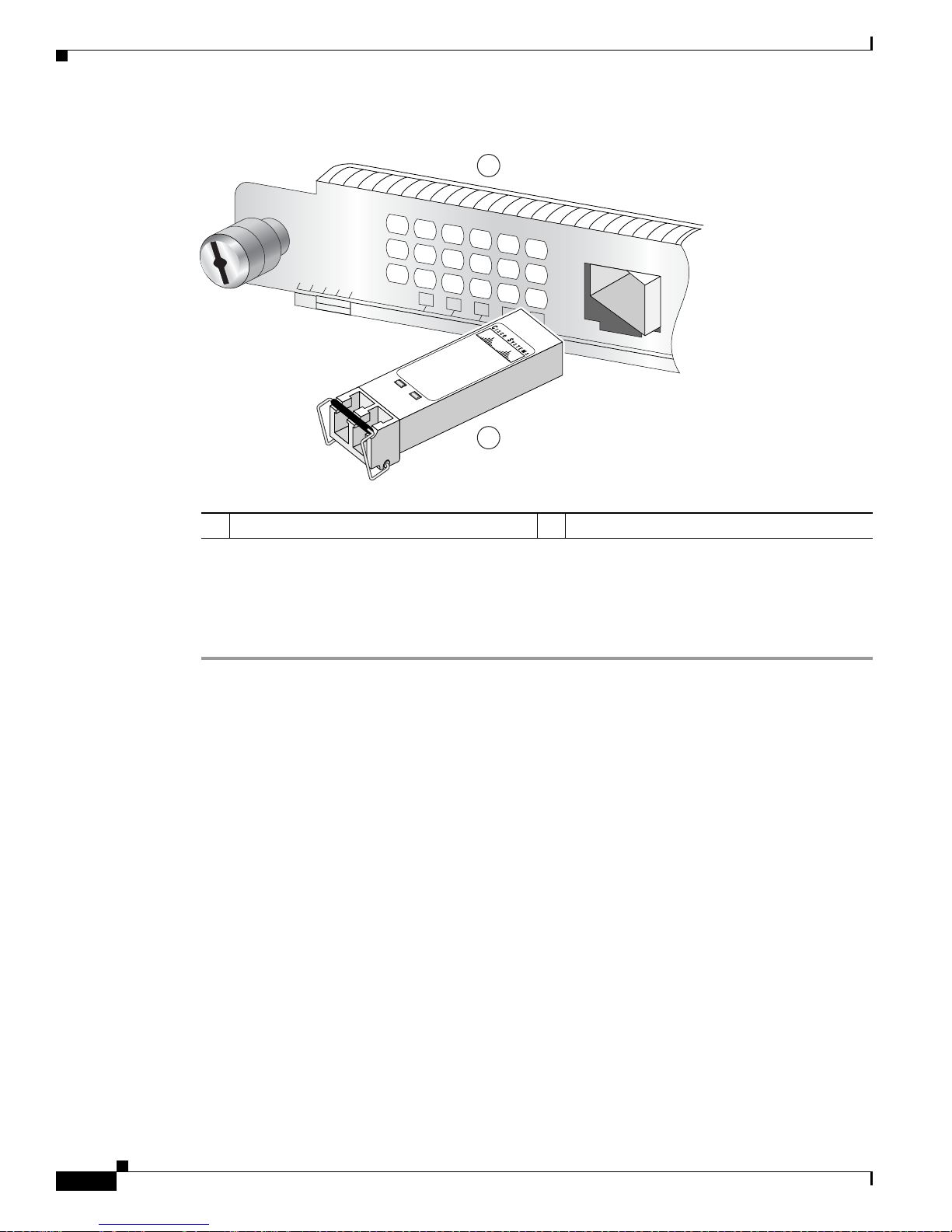
Creating a Four-Node DPT Ring
Figure 3-14 Installing the Bale Clasp SFP Module in the RPR/SRP Uplink Card
10720-RPR-SFP
ACTIVE
CARRIER
RX PKT
P ASS THRU
PROTECT
1
30-1299-01
1000Base-LX
2
Chapter 3 Installing the Cisco 10720 Internet Router
1
122091
1 RPR/SRP uplink card 2 OC48 SFP module
Step 4 Close the bale clasp on the SFP module by pushing the clasp in the upward direction before inserting the
SFP module.
Step 5 Insert the SFP into the appropriate OC48 port and gently push on it until the SFP module snaps into the
slot. (See
Figure 3-14.)
For some basic troubleshooting tips, see the “Basic Troubleshooting SRP for the Uplink Card” section
on page 4-7.
Creating a Four-Node DPT Ring
Create a four-node DPT ring by connecting the fiber-optic cables to DPT uplink cards that are installed
in routers on the network. To create a four-node DPT ring, perform the following steps:
Cisco 10720 Internet Router Installation and Configuration Guide
3-14
78-13062-10
Page 65

Chapter 3 Installing the Cisco 10720 Internet Router
Figure 3-15 Creating a DPT Ring Using Uplink Line Cards
Creating a Four-Node DPT Ring
Tx
Rx
Tx
Rx
Node 1Node 4
ACTIVE
CARRIER
RX PKT
WRAP
PASS THRU
ACTIVE
CARRIER
RX PKT
WRAP
PASS THRU
10720-SR-LC
Tx
TX RX TX RX
A B
Rx
Tx
Rx
Node 3
Tx
Rx
ACTIVE
CARRIER
RX PKT
WRAP
PASS THRU
10720-SR-LC
Tx
TX RX TX RX
A B
Rx
Node 2
Tx
Rx
ACTIVE
CARRIER
RX PKT
WRAP
PASS THRU
10720-SR-LC
Tx
TX RX TX RX
A B
Rx
Step 1 Install a DPT uplink card in a Cisco 10720 Internet Ro uter on the ne twork.
10720-SR-LC
TX RX TX RX
A B
57876
Step 2 Choose a router with an uplink card to become Node 1 in the four-node DPT ring.
Note The TX side B port on Node 1 goes to the RX side A port on the next router, which will become
Node 2. The labels above the f iber con nectors i dentify si de A (lef t port) TX and RX, and sid e B
(right port) TX and RX. (See Figure 3-15.)
Step 3 Add other nodes to the ring by connecting the receive (RX) and transmit (TX) cables. The RX port on
one uplink card must be connected to a TX port on the next uplink card. (See
Figure 3-15.)
Use Figure 3-15 and Table 3-1 to help organize the cable connections for a four-node DPT ring.
Figure 3-16 provides a view of the network when a four-node DPT ring is created.
78-13062-10
Cisco 10720 Internet Router Installation and Configuration Guide
3-15
Page 66

Creating a Four-Node DPT Ring
Figure 3-16 Four-node DPT Ring
Chapter 3 Installing the Cisco 10720 Internet Router
1
A
RX
TX
TX
Node 1
RX
TX
B
Node 4
TX
2
RX
A
RX
B
TX
B
Node 2
RX TX
Inner ring
Outer ring
RX
TX
Node 3
2
B
TX
RX
A
Tab le 3-1 Cable Connections for a Four-Node DPT Ring
Cable Connections
From Node / Connector To Node / Connector
Node 1 / TX side B Node 2 / RX side A
Node 2 / TX side B Node 3 / RX side A
Node 3 / TX side B Node 4 / RX side A
Node 4 / TX side B Node 1 / RX side A
Node 1 / TX side A Node 4 / RX side B
Node 4 / TX side A Node 3 / RX side B
Node 3 / TX side A Node 2 / RX side B
Node 2 / TX side A Node 1 / RX side B
RX
2
A
57877
Cisco 10720 Internet Router Installation and Configuration Guide
3-16
78-13062-10
Page 67
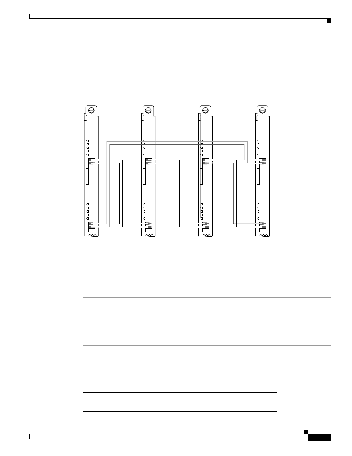
Chapter 3 Installing the Cisco 10720 Internet Router
Creating a Four-Node IEEE 802.17 RPR Mode Ring
Creating a Four-Node IEEE 802.17 RPR Mode Ring
Use Figure 3-17 and Table 3-2 to help organize the cable connections for a four-node IEEE 802.17 RPR
mode ring.
Figure 3-17 Creating an IEEE 802.17 RPR Mode Ring Using RPR/SRP Uplink Cards
Tx
Rx
Tx
Rx
Node 1Node 4
10720-SR-LC
ACTIVE
CARRIER
RX PKT
WRAP
PASS THRU
TX RX TX RX
A B
57876
ACTIVE
CARRIER
RX PKT
WRAP
PASS THRU
10720-SR-LC
Tx
TX RX TX RX
A B
Rx
Tx
Rx
Node 3
Tx
Rx
ACTIVE
CARRIER
RX PKT
WRAP
PASS THRU
10720-SR-LC
Tx
TX RX TX RX
A B
Rx
Node 2
Tx
Rx
ACTIVE
CARRIER
RX PKT
WRAP
PASS THRU
10720-SR-LC
Tx
TX RX TX RX
A B
Rx
The TX span East port on Node 1 goes to the RX span West port on the next router, which will become
Node 2. The labels above the fiber connectors identify span West (left port) TX and RX, and span East
(right port) TX and RX. (See
Figure 3-17.)
Create a four-node IEEE 802.17 RPR mode ring by connecting the fiber -optic cables to RPR/SRP uplink
cards that are installed in routers on the network. To create a four-node IEEE 802.17 RPR mode ring,
perform the following steps:
Step 1 Install an RPR/SRP uplink card in a Cisco 10720 Internet Router on the networ k.
Step 2 Choose a router with an RPR/SRP uplink card to become Node 1 in the four-node IEEE 802.17 RPR
mode ring.
Step 3 Add nodes to the ring by connecting the receive (RX) and transmit (TX) cables. The RX port on one
RPR/SRP uplink card must be connected to a TX port on the next RPR/SRP uplink card.
Tab le 3-2 Cable Connections for a Four-Node IEEE 802.17 RPR Mode Ring
Cable Connections
From Node / Connector To Node / Connector
Node 1 / TX span East Node 2 / RX span West
Node 2 / TX span East Node 3 / RX span West
78-13062-10
Cisco 10720 Internet Router Installation and Configuration Guide
3-17
Page 68
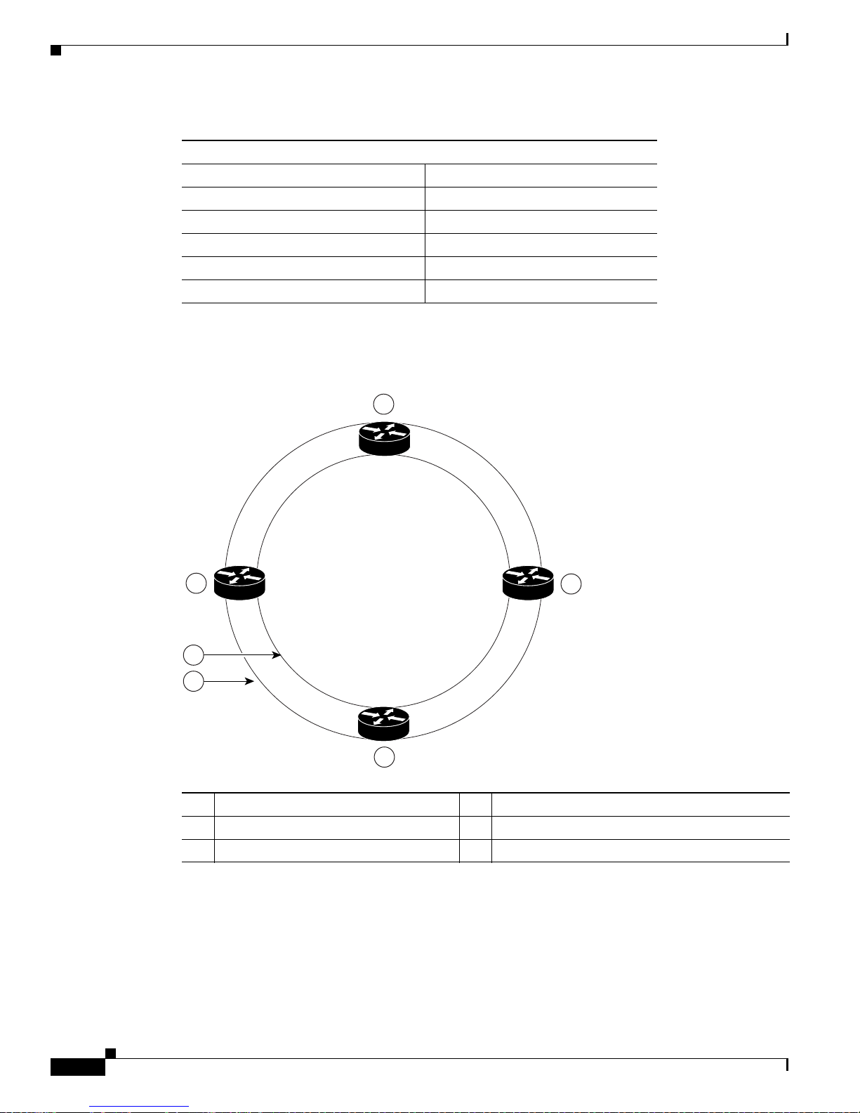
Creating a Four-Node IEEE 802.17 RPR Mode Ring
Table 3-2 Cable Connections for a Four-Node IEEE 802.17 RPR Mode Ring (continued)
Cable Connections
Node 3 / TX span East Node 4 / RX span West
Node 4 / TX span East Node 1 / RX span West
Node 1 / TX span West Node 4 / RX span East
Node 4 / TX span West Node 3 / RX span East
Node 3 / TX span West Node 2 / RX span East
Node 2 / TX span West Node 1 / RX span East
Figure 3-18 provides a view of the network when a four-node IEEE 802.17 RPR mode ring is created.
Figure 3-18 Four Node IEEE 802.17 RPR Mode Ring
RX
Chapter 3 Installing the Cisco 10720 Internet Router
1
TX
RX
East
TX
RX
West
East
RX
2
TX
West
TX
East
West
RX
802.17 Mode
TX
TX
4
RX
5
6
RX
East
TX
TX
West
RX
3
121184
1 Node 1 4 Node 4
2 Node 2 5 Inner Ring—Ringlet 1
3 Node 3 6 Outer Ring—Ringlet 0
Cisco 10720 Internet Router Installation and Configuration Guide
3-18
78-13062-10
Page 69

Chapter 3 Installing the Cisco 10720 Internet Router
Creating a Four-Node IEEE 802.17 RPR Mode Ring
Additional Ports on the Uplink Cards
You can connect the console or serial (AUX) port on the uplink cards to any of the following:
• Terminal server
• Access server
• Modem
• Desktop computer
• Laptop
• Terminal
The console and AUX ports are located on the right side of the uplink card.
Note Cisco Systems does not provide AUX port cables. Cables are available from commercial cable
vendors.
Attaching a Terminal Server or Access Server to the Console or AUX Port
To connect a terminal server or access server to the AUX port of the router, do the following:
Note Attaching a terminal server or access server to the AUX port is a default setting.
Step 1 Attach an ESD-preventive wri st strap t o you r wrist, and to the router or to a bare metal surf ace. (See the
“Preventing Electrostatic Discharge” section on page 2-3.)
Step 2 Verify that the terminal server is turned off and disconnected from its power source.
Step 3 Attach the terminal server end of the RJ-45 cable to the interface port on the terminal server.
Step 4 Attach the other end of the RJ-45 cable to the router console or AUX port.
Step 5 Configure the terminal server for reverse Telnet.
Step 6 Use the default configuration value on the console port or AUX port to configure the terminal router.
Step 7 Use the following configuration on the asynchronous port:
!
interface Loopback0
ip address 10.1.1.1 255.255.255.0
no ip directed-broadcast
!
line 8 <=the c10720 console or AUX port is connected to line 8
exec-timeout 0 0 <==(Optional) make the telnet connection over this line not to timeout
forever
transport input all <==allow reverse telnet
Step 8 To reverse Telnet to the router from the terminal server, use the following command on a PC in the
network:
C:> telnet 10.1.1.1 2008
78-13062-10
Cisco 10720 Internet Router Installation and Configuration Guide
3-19
Page 70

Creating a Four-Node IEEE 802.17 RPR Mode Ring
Attaching a Modem to the Console or AUX Port
To connect a modem to the AUX port on the router, do the following:
Note Attaching a modem to the AUX port is a default setting.
Step 1 Attach an ESD-preventiv e wri st strap t o you r wrist , a nd to the router or to a bare metal surf ace. (See the
“Preventing Electrostatic Discharge” section on page 2-3.)
Step 2 Verify that the modem is turned off and disconnected from its power source.
Step 3 Attach an adapter marked “MODEM” (Part Number CAB-25AS-MMOD) to the modem end o f t he RJ-45-
to-RJ-45 cable.
Step 4 Connect the interface port to the modem.
Step 5 Attach the other end of the RJ-45 cable to the router AUX port.
Step 6 Configure the router for modem dial-in by using the interface asychronous 1 and line aux 0 commands
in the following configuration example:
!
hostname Esop
!
enable password Sherman
!
username Peabody password 0 Sherman <= user name and password for dial-in PPP
authentication
!
interface asynchronous 1
ip address 145.168.1.1 255.255.255.0
no ip directed-broadcast
encapsulation ppp
dialer in-band <= Allow asynchronous dial-in
async mode interactive
peer default ip address 150.168.1.100 <= assign a ip address to the remote PC
ppp authentication chap <= PPP authentication with CHAP
!
!
line aux 0
password cisco
login
modem InOut <=allow modem dial in and dial out
modem autoconfigure type usr_sportster <=specify the modem type
autoselect during-login
autoselect ppp <=Launch PPP when dial-in is successful.
transport input all <=allow all types of terminal sessions, such as telnet
stopbits 1
speed 19200
flowcontrol hardware
!
end
Chapter 3 Installing the Cisco 10720 Internet Router
Cisco 10720 Internet Router Installation and Configuration Guide
3-20
78-13062-10
Page 71

Chapter 3 Installing the Cisco 10720 Internet Router
Creating a Four-Node IEEE 802.17 RPR Mode Ring
Connecting a Desktop Computer, Laptop, or Terminal to the Console or AUX Port
When a desktop computer, laptop, or terminal is connected directly to the console port, you can always
access the router at any privilege le vel without an enable password or enable secret global conf iguration
command configured on the router. (See the
The AUX port requires an enable password or enable secret password configured on the router;
otherwise, the desktop computer, laptop, or terminal cannot access the enable mode of the router.
The asynchronous interface (interface async 1) can be configured for line 1, which is the AUX port. The
AUX por t can be connected to a modem. However, no asynchronous interface can be configured for the
console port; therefore, the console port cannot connect to a modem.
The console and AUX ports support different baud rates:
• Console—9600 (non-configurable)
• AUX—4800 to 115200 (configurable)
To connect the router to a desktop computer, laptop, or terminal via the console or AUX port, perform
the following:
Step 1 Attach an ESD-preventive wri st strap t o you r wrist, and to the router or to a bare metal surf ace. (See the
“Preventing Electrostatic Discharge” section on page 2-3.)
“Assigning Passwords” section on page 3-33.)
Step 2 Verify that the desktop computer, laptop, or terminal is turned off and disconnected from its power
source.
Step 3 Attach the desktop computer, laptop, or terminal end of the RJ-45-to-DB9 female connector cable to the
computer or terminal serial port on the router.
Step 4 Attach the other end of the RJ-45 cable to the router console or AUX port.
Note For more information, refer to the Cabling Guide for Console and AUX Ports guidelines at
http://www.cisco.com/warp/public/701/14.html.
Step 5 Configure the router and the desktop computer, laptop, or terminal u sing the default configuration v alues
for the console port or AUX port. (See
Tab le 3-3 Cisco 10720 Internet Router Default Port Configurations
Table 3-3.)
Function Default Settings
Speed 9600
Data bit 8
Stop bit 2
Parity –
Flow control –
Step 6 Configure the desktop computer, laptop, or terminal serial port with the same port configuration values
required by the router. (See
78-13062-10
Table 3-3.)
Cisco 10720 Internet Router Installation and Configuration Guide
3-21
Page 72

Chapter 3 Installing the Cisco 10720 Internet Router
Connecting Ethernet Ports on the Access Card
Connecting Ethernet Ports on the Access Card
Install the cable-management tray before you connect the copper or optical fiber cable to a F ast Ethernet
port or to an SFP module on the Gigabit Ethernet port on the access card. For more information, see the
“Removing the Cable-Management System ” section on p age 5-68.
For cable and connection specifications, refer to the Cisco 10720 Internet Router Access Card
Installation and Configuration publication. See Figure 3-21 for an example of a typical cable used for
the access card.
To connect the interface cables to the access card ports, perform the following:
Step 1 Attach an ESD-preventive wrist strap to your wrist, and to the router or to a bare metal surface. See the
“Preventing Electrostatic Discharge” section on page 2-3.
Step 2 Verify that the router is turned off and disconnected from its power source
Installing a small form-factor pluggable Gigabit Ethe rnet (GE) (SFP) modul e in the access card GE port
is described in the following sections:
• Installing a Bale Clasp SFP, page 3-22
• Installing a Latch SFP, page 3-23
Note You do not need to power down the router before you install an SFP. The router may remain powered
up during this procedure.
Note The Fast Ethernet ports are suitable for connection to intra-building wiring only, as per GR-1089,
Issue 3.
Installing a Bale Clasp SFP
To install a bale clasp GE SFP module in the access card, perform the following steps:
Step 1 Attach an ESD-preventive strap to your wrist, and to the router or to a bare metal surface. (See the
“Preventing Electrostatic Discharge” section on page 2-3.)
Step 2 Hold the SFP module with the hardware label facing up, as illustrated in Figure 19.
Caution The SFP module must be inserted with the hardware label facing up to avoiding damaging the SFP
module or the access card.
Cisco 10720 Internet Router Installation and Configuration Guide
3-22
78-13062-10
Page 73

Chapter 3 Installing the Cisco 10720 Internet Router
Figure 19 Installing the Bale Clasp SFP Module in the Access Card
Connecting Ethernet Ports on the Access Card
10720-GE-FE-TX
ERROR (R)
LINK ACTIVE (G)
30-1299-01
1000Base-LX
1
70188
2
1 4-Port Gigabit Ethernet 8-Port
2 SFP module
10/100BASE-TX access card
Caution Close the bale lever on the SFP module prior to inserting the SFP module into the port cage to ensure proper
engagement. The bale lever is considered closed when it is in the upright position. See
Figure 3-14. If the bale
lever is left open during insertion, there is a possibity that the SFP module may become stuck in the port cage.
T o remove the SFP module, use a small flathead screwdriver to gently lift the cage tongue (located underneath
the SFP module) away from the SFP module body, thus disengaging the SFP module. The SFP module is not
damaged by this operation.
Step 3 Close the bale clasp in the upward direction before inserting the SFP module.
Step 4 Insert the SFP into the appropriate Gigabit Ethernet slot and gently push on it until the module snaps
into the slot tightly. (See
Installing a Latch SFP
To install a latch SFP module in the access card, perform the following steps:
Step 1 Attach an ESD-preventive strap to your wrist, and to the router or to a bare metal surface. (See the
“Preventing Electrostatic Discharge” section on page 2-3.)
Step 2 Hold the SFP module with the hardware label facing up, as illustrated in Figure 20.
Caution The SFP module must be inserted with the hardware label facing up to avoiding damaging the SFP
module or the access card.
Step 3 Insert the SFP into the appropriate Gigabit Ethernet slot and gently push on it until the module snaps
into the slot tightly. (See
Figure 19.)
Figure 20.)
78-13062-10
Cisco 10720 Internet Router Installation and Configuration Guide
3-23
Page 74

Connecting Ethernet Ports on the Access Card
Figure 20 Installing the Latch SFP Module in the Access Card
Chapter 3 Installing the Cisco 10720 Internet Router
10720-GE-FE-TX
ERROR (R)
LINK ACTIVE (G)
1000Base-LX
TX
RX
30-1299-01
1
70058
2
1 4-Port Gigabit Ethernet
2 SFP module
8-Port10/100BASE-TX access card
Note Before installing optical fiber cables, clean the optical fiber cable connection. See the Inspection and
Cleaning Procedures for Fiber-Optic Connections document.
Step 4 Connect the appropriate interface cable to the access card. (See Figure 3-21 for an example.)
Note For specific cabling specifications, refer to the Cisco 10720 Internet Router Access Card
Installation and Configuration publication.
Figure 3-21 Connecting the Interface Cable (Typical)
U
R
E
R
IE
T
H
IV
R
K
T
P
T
R
P
C
A
S
A
X
A
S
R
C
R
A
W
P
R
CO
NSOLE
AUX
1
1 Ethernet interface cable
ESET
OVERTEMP
CARD FAIL
SYSTEM STAUS
POWER
IL
A
)
F
(G
D
B
E
R
A
IV
M
C
0
T
0
C
1
/A
K
IN
L
CARD FAIL
POWER
DON NOT REM
OR INSERT CABLES
W
ITH THE POW
S
P
OVE
ER ON
AC OK
DC OK
OTF
AC OK
DC OK
OTF
INPUT 100-200- 50/60Hz 2-5A
57745
Cisco 10720 Internet Router Installation and Configuration Guide
3-24
78-13062-10
Page 75

Chapter 3 Installing the Cisco 10720 Internet Router
In-Band Ethernet Port
In-band Ethernet is connected to the hub by using one of the Fast Ethernet or Gigabit Ethernet ports on
the access card. Out-of-band Ethernet is not available on the Cisco
Installing the Cable-Management System
The cable-management system, located on the front of the router , or ganizes the inte rface cables. To keep
the cables free of sharp bends, extend the cables from the center out both sides of the cable-management
system. Excessive bending of an interface cable can degrade performance and possibly harm the cable.
Perform the following steps to install the cable-management system:
Step 1 Attach an ESD-preventive wri st strap t o you r wrist, and to the router or to a bare metal surf ace. (See the
“Preventing Electrostatic Discharge” section on page 2-3.)
Figure 3-22 Attaching the Cable-Management Tray
Installing the Cable-Management System
10720 Internet Router.
U
R
E
R
IE
H
IV
R
KT
T
R
P
CT
AP
S
X
A
S
R
CA
R
A
W
P
R
E
S
E
T
S
C
O
U
P
N
TA
S
M
IL
O
L
E
A
U
X
V
O
CAR
LINK/ACTIVE (G)
A
C
A
S
C
O
TE
K
FA
R
R
EM
D
E
E
T
R
S
W
A
O
C
D
C
SY
O
P
K
O
T
F
D FAIL
100 MBPS
AIL
F
R
D
E
R
W
O
A
C
O
P
K
D
C
O
K
O
T
F
D
O
N
N
O
T
R
E
M
O
O
V
R
E
IN
S
E
R
T
C
A
B
W
LE
IT
H
S
T
H
E
P
O
W
E
R
O
N
IN
P
U
T
1
0
0
-2
0
0
- 5
0
/6
0
H
z
2
-5
A
66296
Step 2 Attach the cable-management tray to the router using four of the 3.5-mm x 6-mm screws that are shipped
with the router. Secure the tray with two screws on each side of the router chassis using a Number 1
Phillips screwdriver. (See
Figure 3-23 Managing Router Cables with the Cable-Management Tray
ACTIVE
CARRIER
RX PKT
WRAP
PASS THRU
Figure 3-22.)
R
E
S
E
T
C
O
N
S
O
L
A
E
A
C
O
OVERTEMP
CARD FAIL
SYSTEM STAUS
IL
A
F
D
E
R
A
C
TIV
C
/A
K
LIN
CARD FAIL
POWER
DON NOT REMOVE
OR INSERT CABLES
WITH THE POWER ON
K
D
C
O
POWER
K
O
T
F
)
S
P
(G
B
100 M
A
C
O
K
D
C
O
K
O
T
F
IN
P
U
T
1
0
0
-2
0
0
- 5
0
/6
0
H
z
2
-5
A
57749
U
X
Step 3 Separate cables and lead them out the sides of the cable-management tray. Use a cable tie to keep the
cables together. (See
78-13062-10
Figure 3-23.)
Cisco 10720 Internet Router Installation and Configuration Guide
3-25
Page 76
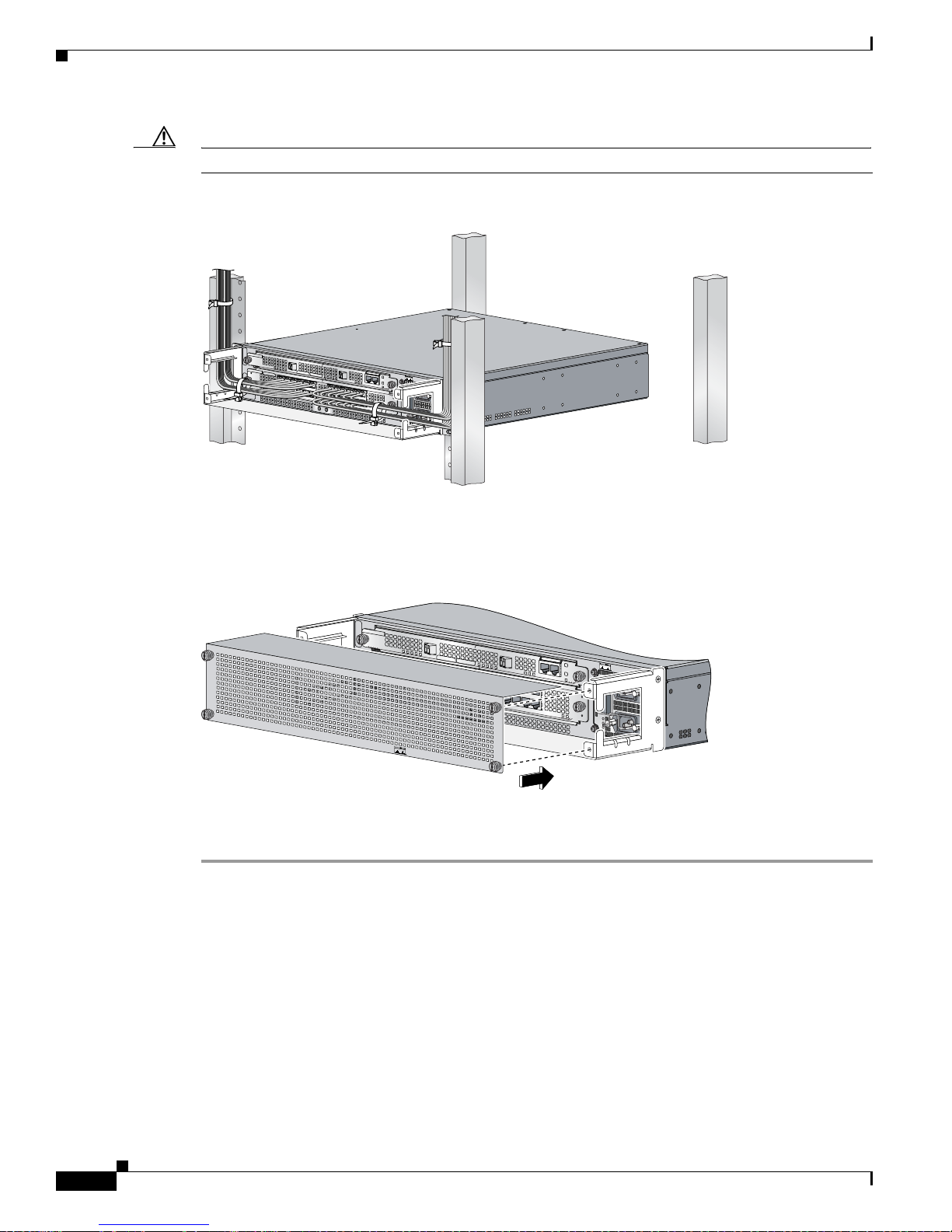
Turning On Power to the Router
Caution To avoid damage to the cables, avoid excessive bending.
Figure 3-24 Cable-Management Tray and Router Installed in a Rack
Chapter 3 Installing the Cisco 10720 Internet Router
U
R
E
R
IE
T
IV
R
K
TH
T
P
R
P
C
A
S
A
X
A
S
R
C
R
A
W
P
R
E
S
E
T
S
U
C
A
P
O
N
T
S
M
IL
O
L
A
E
E
S
A
C
O
A
T
K
U
M
F
X
R
R
E
D
E
E
T
R
V
S
W
A
O
Y
O
C
D
C
S
P
O
K
O
T
F
L
I
A
)
F
S
G
(
P
D
B
E
R
V
M
A
I
C
0
T
0
C
1
A
/
K
N
I
L
IL
A
F
R
D
E
R
W
A
O
A
C
C
O
P
K
D
C
O
K
O
T
F
D
O
N
N
O
T
R
E
M
O
O
V
R
E
I
N
S
E
R
T
C
A
B
W
L
I
E
T
H
S
T
H
E
P
O
W
E
R
O
N
I
N
P
U
T
1
0
0
-2
0
0
-
5
0
/
6
0
H
z
2
-
5
A
57844
Step 4 Use cable ties to secure the cables to the equipment mounting rack to keep the wires from accidental
bends or breaks. (See
Figure 3-24.)
Figure 3-25 Installing the Cable-Management Cover
IER
ACTIVE
RAP
CARR
RX PKT
W
PASS THRU
RESET
CONSOLE
P
AC
STAUS
TEM
RD FAIL
OVER
CA
SYS
CARD FAIL
100 MBPS
LINK/ACTIVE (G)
ER
CARD FAIL
POW
DON NOT REMO
OR INSERT CABLES
W
ITH THE POW
O
K
ER
TEM
DC O
POW
K
O
TF
AC
O
K
D
C
O
K
O
TF
VE
ER ON
IN
PUT 100-200- 50/60Hz 2-5A
66298
AUX
CISCO 10720 INTERNET ROUTER
Step 5 Using a Number 1 Phillips screwdriver, attach the cable-management cover to the cable-management
tray. (See
Figure 3-25.)
Go to the “Turning On Power to the Router” section on page 3-26 for information on powering on the
router.
Turning On Power to the Router
Perform the following steps to restore power to the router:
• Connecting the AC Power Supply, page 3-27
• Connecting the DC Power Supply, page 3-29
Cisco 10720 Internet Router Installation and Configuration Guide
3-26
78-13062-10
Page 77

Chapter 3 Installing the Cisco 10720 Internet Router
Connecting the AC Power Supply
Turning On Power to the Router
Warning
Before you install, operate, or service the system, read the
Information for the Cisco 10720 Internet Router publication.
Regulatory Compliance and Safety
This publication contains important safety
information you should know before working with the system.
Warning
Read the installation instructions before you connect the system to its power source.
Statement 1004
Note For additional information, refer to the Cisco 10720 Internet Router AC and DC Power Supply
Replacement Instructions. This configuration note is available on Cisco.com or ordered as a printed
document. Field replacement documentation is available electronically, by default. If you prefer
printed documentation, order it online.
Note We recommend that you attach each AC-input power supply to a dedicated power source for
redundancy and use an uninterruptable power supply (UPS) to protect against power failures. Each
AC power supply operating between 100 and 240 VAC requires a dedicated 15 A electrical power
service for North America, 10 A electrical power service for inter nationa l specifications .
Perform the following steps to connect the AC power supply:
Step 1 Confirm that the power switch on the router is in the off (O) position. (See Figure 3-26.)
Figure 3-26 AC Power Cord Connected to the Router
AC OK
DC OK
OTF
AC OK
DC OK
OTF
57869
Step 2 Connect the AC power cord to the AC power supply receptacle on the router. (See Figure 3-26.)
78-13062-10
Cisco 10720 Internet Router Installation and Configuration Guide
3-27
Page 78

Turning On Power to the Router
Figure 3-27 Power Cord Secured with a Wire Br acket
Step 3 Close the wire bracket over the power cord plug. (See Figure 3-27.)
Chapter 3 Installing the Cisco 10720 Internet Router
IN OK
DC
OTF
IN OK
DC
OTF
57858
Figure 3-28 Router Connected to the Power Source
U
R
E
R
IE
T
H
IV
R
K
T
P
T
R
P
C
A
S
A
X
A
S
R
C
R
A
W
P
R
E
S
E
T
S
U
C
A
P
O
N
T
S
M
IL
O
L
A
E
E
S
A
C
O
A
T
K
U
M
F
X
R
R
E
D
E
E
T
R
V
S
W
A
O
Y
O
C
D
C
S
O
P
K
O
T
F
L
I
A
)
F
S
G
(
P
D
B
E
R
V
M
A
I
C
0
T
0
C
1
A
/
K
N
I
L
IL
A
F
R
D
E
R
W
A
O
A
C
C
O
P
K
D
C
O
K
O
T
F
D
O
N
N
O
T
R
E
M
O
O
V
R
E
I
N
S
E
R
T
C
A
B
W
L
IT
E
H
S
T
H
E
P
O
W
E
R
O
N
IN
P
U
T
1
0
0
-2
0
0
- 5
0
/6
0
H
z
2
-5
A
57870
Step 4 Connect the other end of the AC power cord to the AC power source outlet. (See Figure 3-28.)
Cisco 10720 Internet Router Installation and Configuration Guide
3-28
78-13062-10
Page 79

Chapter 3 Installing the Cisco 10720 Internet Router
Figure 3-29 Power Switch in the On Position
IN OK
DC
OTF
IN OK
DC
OTF
Step 5 Press the power switch to on the (–) po sition. (See Figure 3-29.)
Turning On Power to the Router
57871
Connecting the DC Power Supply
Warning
Warning
Note The battery return connection is to be trea ted as an isolated D C retur n (i.e. DC-I), a s defined in
Note The minimum wire gauge size supported on the DC dual power supply is 17 American Wire Gauge
When you install the unit, the ground connection must always be made first and disconnected last.
Statement 42
Before performing any of the following procedures, ensure that the power is removed from the DC
circuit. Ensure that power is removed from the DC circuit. To ensure that all power is off, locate
the circuit breaker on the panel board that services the DC circuit. Switch the circuit breaker to
the off (O) position, and tape the switch handle of the circuit breaker in the off (O) position.
Statement 140
GR-1089-CORE, Issue 3.
(AWG), which has a 1.5mm wire diameter. The maximum wire gauge size supported on the DC dual
power supply is 10 AWG, which has a 6mm wire diameter.
78-13062-10
Cisco 10720 Internet Router Installation and Configuration Guide
3-29
Page 80

Turning On Power to the Router
Connect the DC power supply by performing the following steps:
Step 1 Verify that the –48V and +48V leads are disconnected from the power source.
Step 2 Attach an ESD-preventive strap to your wrist, and to the router or to a bare metal surface. (See the
“Preventing Electrostatic Discharge” section on page 2-3.)
Figure 3-30 Power Switch in the Off Position
Chapter 3 Installing the Cisco 10720 Internet Router
IN OK
DC
OTF
IN OK
DC
OTF
57872
Step 3 Verify that the power switch located on the front of the power supply is in the off (O) position. (See
Figure 3-30.)
Figure 3-31 Tightening the DC Lead Receptacle
1
122053
1 Ground lead
Step 4 Insert the stripped end of the ground lead all the way into the ground lead receptacle on the DC-input
power supply and tighten the receptacle scre w using a 1/8-inch flat-blade scre wdri ver. (See
Figure 3-31.)
Note Make sure the entire stripped end of each lead is inserted all the way into its receptacle. If any
exposed wire at the stripped end of a lead is visible after inserting the lead into its receptacle, remove
the lead from the receptacle. Use a wire cutter to cut the stripped end of the lead to fit the receptacle.
Cisco 10720 Internet Router Installation and Configuration Guide
3-30
78-13062-10
Page 81

Chapter 3 Installing the Cisco 10720 Internet Router
Figure 3-32 Connecting the DC Power Leads
Turning On Power to the Router
1
2
5
4 4
1 Ground lead connected 4 Ground lead
2 Positive lead connected 5 Positive lead
3 Negative lead connected 6 Negative lead
Step 5 Connect the power leads in the following order:
a. Ground (green wire) (See 4 in Figure 3-32.)
b. Positive (white wire) (See 5 in Figure 3-32.)
c. Negative (black wire) (See 6 in Figure 3-32.)
Figure 3-33 DC Power Leads Secured with a Cable Tie
3
6
5
122049
4
IN OK
DC
OTF
IN OK
DC
OTF
1
2
3
122054
1 Negative lead 3 Ground lead
2 Positivelead
Step 6 After tightenin g the rec epta cle screw for the gro und, +4 8V, and –48V DC-input leads, use cable ties to
secure the three leads. (See
Figure 3-33.)
78-13062-10
Cisco 10720 Internet Router Installation and Configuration Guide
3-31
Page 82

Initial Setup Configuration
Note Leave a small service loop in the ground lead to ensure that the ground lead is the last lead to
disconnect from the power supply if a great deal of strain is plac ed on the DC-input leads. It is
important that the ground power lead is the last to disconnect from the power supply terminal.
Note Allow sufficient slack in the power cable leads for strain relief. The power cable leads should be
adequately secured to prevent the power supply terminal connections from being subjected to strain.
Step 7 After wiring the DC power supply, remove the tape from the circuit breaker switch handle and turn on
power by moving the handle of the circuit breaker to the on position.
If you are installing the cable-management system, go t o the “Verifying the Router Power Is Turned On”
section on page 3-32. If not, install the cables, and then power up the router.
Verifying the Router Power Is Turned On
Chapter 3 Installing the Cisco 10720 Internet Router
Check the following to ensure the router is properly powered on:
• LED lights are on.
• Fans are running.
• Power switch indicates router is turned on.
Initial Setup Configuration
The initial setup configuration for the router is presented in the following sections:
• Configuring the Router, page 3-32
• Configuring Global Parameters Using the Setup Facility, page 3-33
Configuring the Router
Perform a basic configuration for the router by using either of the following methods:
• Method 1—Using the setup facility or the setup command.
During the startup of an unconfigured router, the system automatically starts the setup facility. The
setup facility enables manual configuration of the router. The setup facility provides a structured,
interactive script to set up the router.
• Method 2—Using the global configuration mode through the command line user interface.
You will need the following information before you set up the router:
• Router interfaces
• Router protocols
• Network addresses for the protocols being configured
• Password scheme
Cisco 10720 Internet Router Installation and Configuration Guide
3-32
78-13062-10
Page 83

Chapter 3 Installing the Cisco 10720 Internet Router
Verifying the Cisco 10720 Internet Router LEDs
Configuring Global Parameters Using the Setup Facility
When using the setup facility or the setup command, the system prompts the user to configure global
parameters for the router. Global parameters are used for controlling sy stem-wide settings, including the
following:
• Host name for the router
• Passwords for the enable secret, enable, and virtual terminal security parameters
• Protocols used by the router
Host Name
The name assigned to the router must follow the rules for ARPANET host names. It must start with a
letter, end with a letter or digit, and have only letters, digits, and hyphens. The name must consist of 63
or fewer characters. For more information, refer to RFC 1035, Domain Names—Implementation and
Specifications.
Do not expect case to be preserved. Conventions dictate that computer names appear all lowercase. For
more information, refer to RFC
1178, Choosing a Name for Your Computer.
Assigning Passwords
The commands available at the user EXEC level are a subset of those available at the privileged EXEC
level. Many privileged EXEC commands are used to set system parameters. You should
password-protect these commands to prevent their unauth orized use. For information on how to establish
password protection or configure privilege levels, refer to the “Configuring Passwords and Privileges”
chapter in the
configuration documentation set that corresponds to the Cisco IOS software release installed on your
Cisco hardware.
The enable secret password functionality is available for the Cisco 10720 Internet Router. Enter th e
correct password to gain access to privileged-level commands. When ROM monitor is activ e, the enable
password can be used, depending on the boot ROM level.
For maximum security, the enable secret and the enable passwords should be different. If the same
password is used for both the enable secret and the enable functions during the setup process, the
system accepts it, but issues a warning indicating that two distinct passwords should be entered.
An enable secret password can contain from 1 to 25 uppercase and lowercase alphanumeric characters.
An enable password can contain any number of uppercase and lowercase alphanumeric characters.
Security Configuration Guide. The publication is located in the Cisco IOS software
Verifying the Cisco 10720 Internet Router LEDs
The router LEDs are included on the access and uplink cards. The access and uplink cards each contain
two sets of LEDs:
• System LEDs
• Status LEDs
The system LEDs inform the user of the condition of the router, while the uplink or access card status
LEDs inform the user of the condition or status of the card itself.
78-13062-10
Cisco 10720 Internet Router Installation and Configuration Guide
3-33
Page 84

Verifying the Cisco 10720 Internet Router LEDs
The following sections provide inf ormation about the uplink card system, uplink card status, access card
system, and access card status LEDs:
• Uplink Card System LEDs, page 3-34
• Uplink Card Status LEDs, page 3-36
• Access Card System LEDs, page 3-38
• Access Card Status LEDs, page 3-39
Uplink Card System LEDs
Chapter 3 Installing the Cisco 10720 Internet Router
Warning
Avoid exposure to laser radiation. Do not stare into an open aperture, because invisible laser
radiation may be emitted from the aperture when a cable is not inserted in the port.
Statement 125
The uplink card system LEDs provide information on the functionality of the uplink card in the router.
The system LEDs are located on the right side of the uplink card. See
Figure 3-34 LEDs on the DPT and
POS/DPT uplink cards.
Figure 3-34 DPT and POS/DPT Uplink Card LEDs (Left) and System LEDs (Right)
TX RX TX RX
10720-SR-LC
CARRIER
ACTIVE
PASS THRU
WRAP
RX PKT
ACTIVE
WRAP
RX PKT
CARRIER
P ASS THRU
A B
CONSOLE AUX
OVERTEMP
RESET
CARD FAIL
SYSTEM STATUS
POWER
SYSTEM STATUS
CARD FAIL
OVERTEMP
POWER
66303
The configuration of the router will affect the uplink LEDs. Possible variations include optical cable
connections and temperature.
Table 3-4 provides a description of the system LEDs on a DPT or POS/DPT uplink card. Table 3-5
provides a description of the LEDs on an RPR/SRP uplink card.
Note The color of the LEDs is green/red on the DPT and POS/DPT uplink cards, and green/amber on the
RPR/SRP uplink card.
Note Table 3-4 and Table 3-5 also indicate the system status of the uplink card as it initializes.
Cisco 10720 Internet Router Installation and Configuration Guide
3-34
78-13062-10
Page 85
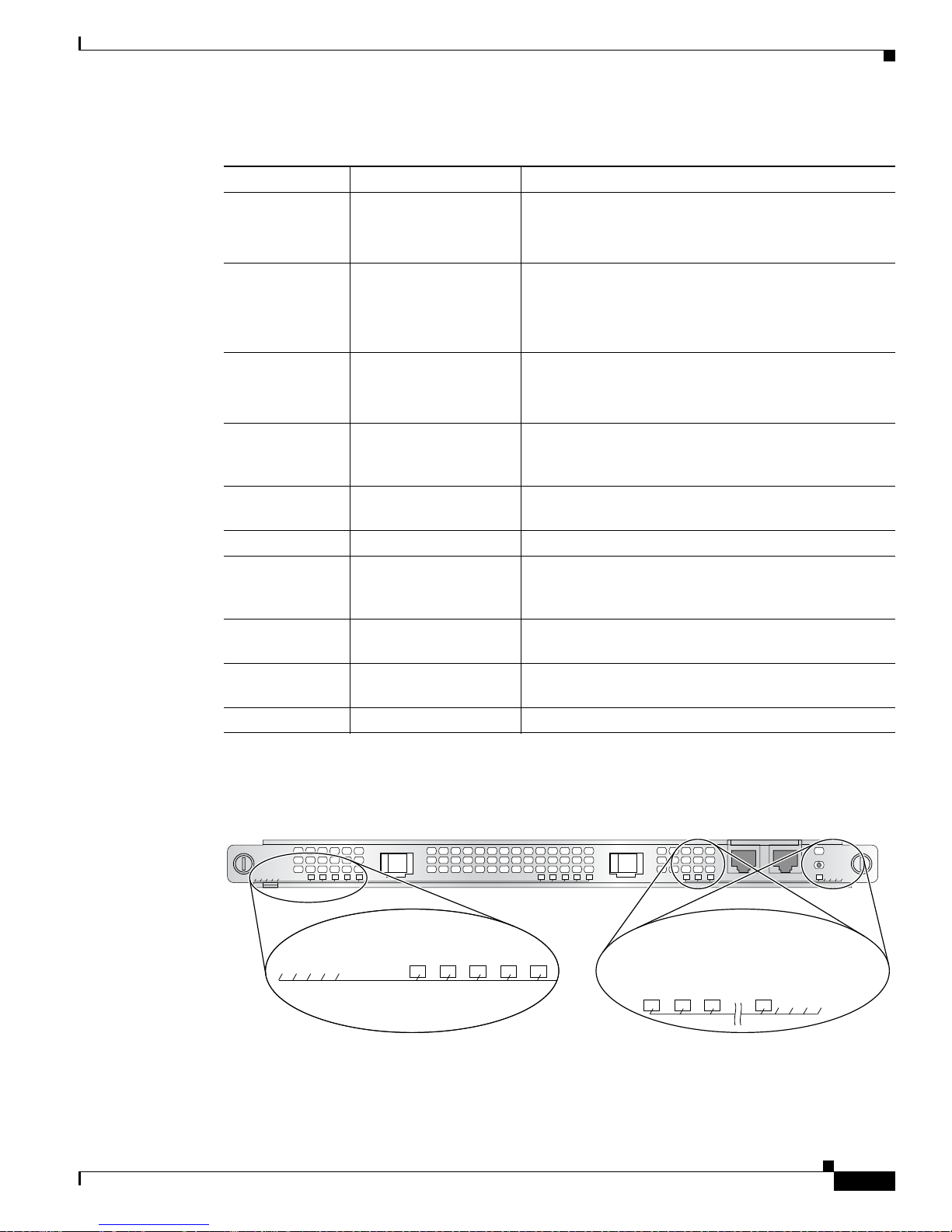
Chapter 3 Installing the Cisco 10720 Internet Router
Tab le 3-4 DPT and POS/DPT Uplink Card System LEDs
LED Activity Description
OVERTEMP
Verifying the Cisco 10720 Internet Router LEDs
Green (default status
when initialized)
Red/Green Both LEDs are on, appearing orange. Systems working
System is operating within the proper temperature
range.
(inlet <104oF [40oC]; outlet <109oF [43oC])
on warning temperature range.
(104oF [40oC] <= inlet < 122oF [50oC], 109oF [43oC] <=
outlet< 127
o
F [53oC])
Red System is working on critical temperature state.
CARD FAIL
(122oF [50oC] <= inlet < 149oF [65oC], 127oF [53oC] <=
outlet < 167
Red A hardware failure is being detected on the uplink card.
o
F [75oC])
During power up, the LED will be red, even when the
uplink card is powered down.
SYSTEM STATUS
Off (default status when
initialized)
Red Not applicable.
Card is operational. The LED is turned off after
hardware initialization.
Red/Green Both LEDs are on, appears orange. This is the normal
configuration during po w er up. Once the softw are loads
successfully, the red LED will turn off.
Green (default status
System is operational.
when initialized)
POWER
Green (default status
The uplink card is receiving power from the system1.
when initialized)
Off Uplink card is not receiving power from the system.
1. System power up is not an indication that the uplink card is powered up. Check the card status LEDs to ensure the card is
functional properly and is receiving power form the system.
Figure 3-35 RPR/SRP Uplink System LEDs
10720-SR-LC
78-13062-10
ACTIVE
RIER
X PK
AR
R
C
U
T
TECT
O
PR
PASS THR
ACTIVE
RX PKT
CARRIER
PROTECT
PASS THRU
1
2
CONSOLE AUX
CARD FAIL
OVERTEMP
TUS
RESET
P
IL
STA
FA
TEM
ER
W
VER
YSTEM
PO
S
CARD
O
SYSTEM STATUS
POWER
116786
Cisco 10720 Internet Router Installation and Configuration Guide
3-35
Page 86

Verifying the Cisco 10720 Internet Router LEDs
Tab le 3-5 RPR/SRP Uplink Card System LEDs
LED Activity Description
OVERTEMP
CARD FAIL
SYSTEM STATUS
POWER
1. System power up is not an indication that the uplink card is powered up. Check the card status LEDs to ensure the card is
functioning properly and is receiving power from the system.
Chapter 3 Installing the Cisco 10720 Internet Router
Green (default status
when initialized)
Amber/green Both LEDs are on (appears orange). System is working
Amber System is working on critical temperature state.
Amber A hardware failure is detected on the uplink car d. During
Off (default status
when initialized)
Amber Not applicable.
Amber/green Both LEDs are on (appears orange). This is the normal
Green (default status
when initialized)
Green (default status
when initialized)
Off Uplink card is not receiving power from the system.
System is operating within the proper temperature range.
(inlet <104oF [40oC]; outlet <109oF [43oC])
on warning temperature range.
(104oF [40oC] <= inlet < 122oF [50oC],
109oF [43oC] <= outlet < 127oF [53oC])
(122oF [50oC] <= inlet < 149oF [65oC],
127oF [53oC] <= outlet < 167oF [75oC])
power up, the LED will be amber even when the uplink
card is powered down.
Card is operational. The LED is turned off after hardware
initialization.
configuration during power up. Once the software loads
successfully, the amber LED will turn off.
System is operational.
Uplink card is receiving power from the system.
1
For more specific information on these and other uplink card LEDs, refer to the Cisco 10720 Internet
Router Uplink Cards Installation and Configuration publication.
Uplink Card Status LEDs
Warning
Cisco 10720 Internet Router Installation and Configuration Guide
3-36
Avoid exposure to laser radiation. Do not stare into an open aperture, because invisible laser
radiation may be emitted from the aperture when a cable is not inserted in the port.
The DPT/POS uplink card status LEDs provide informatio n on the operational stat us of the DPT or POS
uplink card. The status LEDs are located on the left side of the DPT and POS uplink cards. See
Figure 3-34 for an example of a typical DPT uplink card.
Table 3-6 provides a description of status LED activity on the DPT uplink card. Table 3-7 provides a
description of status LED activity on the POS/DPT uplink card. Table 3-8 provides a description of
status LED activity on the RPR/SRP uplink card.
Statement 125
78-13062-10
Page 87

Chapter 3 Installing the Cisco 10720 Internet Router
Note The color of the LEDs is green/red on the DPT and POS/DPT uplink cards, and green/amber on the
RPR/SRP uplink card.
Verifying the Cisco 10720 Internet Router LEDs
Tab le 3-6 DPT Uplink Card Status LEDs
LED Activity Description
ACTIVE
Green The port is active.
Blinking red Fiber misconnect is detected (that is, side A
connected to neighbor side A).
Off The port is not active.
CARRIER
Green Framer has locked onto the SONET frames.
Off Framer has not achieved lock.
RX PACKET
Green Packets are being received on the port.
1,2
Off No packets are being received on the port.
WRAP
Red Port is in local wrap.
Green Wrap in system (for example, another port on
the ring is wrapped).
Off No wrap (i.e., the port is operating normally).
PASS THR U
Green Port is in Pass-thru mode.
Off Port is operating normally.
1. Note that due to the SRP IP packets, this LED will remain permanently lit during normal SRP
operation.
2. After you shut down the port interface on the uplink card, the RX PKT LED remains on if SRP
packets (including transit SRP packets) are still being received in Pass-thru mode. The RX
LED turns off if no SRP packets are received.
PKT
78-13062-10
Tab le 3-7 POS/DPT Uplink Card Status LEDs
LED Activity Description
ACTIVE
Green Port is active.
Off Port is not active.
CARRIER
Green Framer has locked onto
the SONET frames.
Off Framer has not achieved
lock.
RX PACKET
Green Packets are being
received on the port.
Off No packets are being
received on the port.
SRP WRAP
SRP PASS THRU
Off Not applicable to POS.
Off Not applicable to POS.
Cisco 10720 Internet Router Installation and Configuration Guide
3-37
Page 88

Verifying the Cisco 10720 Internet Router LEDs
Note Note that the RPR/SRP uplink card uses the label “PROTECT” instead of “WRAP,” and the positions of
these two LEDs are different from that on the DPT or POS/DPT uplink card.
Tab le 3-8 RPR/SRP Uplink Status LEDs
LED Activity Description
ACTIVE
CARRIER
RX PKT
PASSTHRU
PROTECT
Chapter 3 Installing the Cisco 10720 Internet Router
Green Port is enabled by software. There is no side mismatch or
loopback.
Amber Loopback is on.
Blinking amber Port is enabled by software and there is a side mismatch. There
is no loopback.
Off Port is not enabled by software
Green Port is up and there is a valid SONET signal without any alarms.
Amber Port is up and there is at least one alarm (LOS, LOF, RDI, and
so on.)
Off Off.
Green Framer is receiving packets.
Off Framer is not receiving packets.
Green Port is in Pass-thru mode.
Off Port is operating normally.
Green Remote wrap.
Off No wrap.
Amber Local wrap.
Blinking green Remote steer.
Blinking amber Local steer.
For more specific information on these and other uplink card LEDs, refer to the Cisco 10720 Internet
Router Uplink Cards Installation and Configuration publication.
For additional information about laser safety requirements, see the “Laser Safety” section on page 2-4.
Access Card System LEDs
Warning
Cisco 10720 Internet Router Installation and Configuration Guide
3-38
Avoid exposure to laser radiation. Do not stare into an open aperture, because invisible laser
radiation may be emitted from the aperture when a cable is not inserted in the port.
The access card system LEDs provide information on the functionality of the access card in the router.
The system LEDs are located on the bottom right side of the access card. (See
Statement 125
Figure 3-36.)
78-13062-10
Page 89
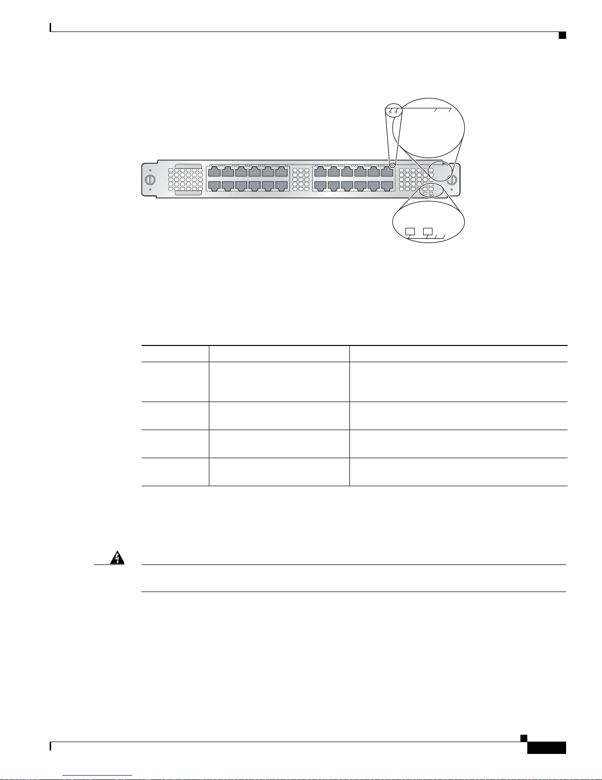
Chapter 3 Installing the Cisco 10720 Internet Router
Figure 3-36 Access Card Status LEDs (Top) and System LEDs (Bottom)
10720-FE-TX
1234567891011
The configuration of the router will affect the access LEDs. Possible variations include optical cable
connections and temperature.
Table 3-9 describes the system LEDs on the access card, and indicates the system status of the access
card as it initializes.
Verifying the Cisco 10720 Internet Router LEDs
100 MBPS
ERROR (R)
LINK/ACTIVE (G)
100 MBPS
ERROR (R)
LINK/ACTIVE (G)
12
1314151617181920212223
24
POWER
CARD FAIL
CARD FAIL
57684
POWER
Tab le 3-9 System LEDs for Access Card
LED Activity Description
CARD FAIL
POWER
1. System power up is not an indication that the access card is powered up.
Access Card Status LEDs
Warning
Avoid exposure to laser radiation. Do not stare into an open aperture, because invisible laser
radiation may be emitted from the aperture when a cable is not inserted in the port.
The access card status LEDs provide information on the operational status of the access card. The status
LEDs are located on the top right side of the access card. See
access card status LEDs.
Red A hardware failure is being detected on the access
card. During power up, the LED will be red, even
when the access card is powered down.
Off (default status when
initialized)
Green (default status when
initialized)
Card is operational. The LED is turned off after
hardware initialization.
The access card is receiving power from the
system.
1
Off The access card does not receive power from the
system.
Statement 125
Figure 3-36 for an example of typical
78-13062-10
Cisco 10720 Internet Router Installation and Configuration Guide
3-39
Page 90

Verifying the Cisco 10720 Internet Router LEDs
Tab le 3-10 Access Card Status LEDs
Port Type LED Activity Description
Gigabit Ethernet ERROR (R)/LINK (G)
Fast Ethernet
10/100BASE-TX
ACTIVE
ERROR (R)/LINK ACTIVE (G)
100 MBPS
Chapter 3 Installing the Cisco 10720 Internet Router
Red Error detected on this
port. It is turned on at
reset and turned off
during hardware
initialization.
Solid Green A link is established on
this port.
Off No link detected on this
port.
Blinking Green Packets are being
received or transmitted
on this port.
Off The port is not active.
Red Error detected on this
port. It is turned on at
reset and turned off
during hardware
initialization.
Solid green A link is established on
this port, but no activity
is detected.
Blinking green Packets are being
received or transmitted
on this port.
Off No link detected on this
port.
Amber This port is set at 100
MB/s. This LED reflects
the status of the Ethernet
PHY chip. Even after the
link is removed, it will
remain in the previous
state.
Off Port is set at 10 MB/s.
Cisco 10720 Internet Router Installation and Configuration Guide
3-40
78-13062-10
Page 91

Chapter 3 Installing the Cisco 10720 Internet Router
Table 3-10 Access Card Status LEDs (continued)
Port Type LED Activity Description
Fast Ethernet 100BASE-FX ERROR (R)/LINK (G)
ACTIVE
Verifying the Cisco 10720 Internet Router LEDs
Red Error detected on this
port. It is turned on at
reset and turned off
during H/W
initialization.
Solid Green A link is established on
this port.
Off No link detected on this
port.
Blinking Amber Packets are being
received or transmitted
on this port.
Off The port is not active.
For a complete description of the access card LEDs, refer to the Cisco 10720 Internet Router Access
Card Installation and Configuration publication.
For additional information about laser safety requirements, see the “Laser Safety” section on page 2-4.
78-13062-10
Cisco 10720 Internet Router Installation and Configuration Guide
3-41
Page 92

Additional Configuration Features
Additional Configuration Features
The following sections provide information on additional router configuration and monitoring
procedures:
• Saving the Configuration to NVRAM, page 3-42
• Using the show Commands, page 3-42
• Monitoring Optical Power, page 3-45
• Configuring Basic SRP Functionality, page 3-46
• Configuring POS Functionality, page 3-46
• Configuring Fast Ethernet, page 3-47
• Configuring Gigabit Ethernet, page 3-47
• Configuring TDR on TX Access Card, page 3-47
• Assigning IP Information, page 3-47
• Enabling Write Permission to Bootflash, page 3-47
• Upgrading the Cisco IOS Software Image, page 3-47
Chapter 3 Installing the Cisco 10720 Internet Router
• Upgrading ROM Monitor, page 3-48
Saving the Configuration to NVRAM
To save your configuration to NVRAM, use the copy running-config startup-config command.
Router# copy running-config startup-config
Destination filename [startup-config]?
Building configuration...
[OK]
Router#
Using the show Commands
You can display router information using the show commands described in the following sections:
• Using the show running configuration Command, page 3-42
• Using the show version Command, page 3-44
• Using the show environment all Command, page 3-45
Using the show running configuration Command
Use the show running-configuration command to verify the router’s configuration.
router# show running-configuration
Building configuration...
Current configuration : 3791 bytes
!
version 12.0
no service pad
service timestamps debug uptime
service timestamps log uptime
Cisco 10720 Internet Router Installation and Configuration Guide
3-42
78-13062-10
Page 93

Chapter 3 Installing the Cisco 10720 Internet Router
no service password-encryption
!
hostname Router
!
boot system flash:c10700-p-mz.120-18.ST
!
ip subnet-zero
!
!
interface SRP1/1
ip address 48.1.1.10 255.255.255.0
no ip directed-broadcast
!
interface FastEthernet2/1
ip address 190.10.1.1 255.255.255.0
no ip directed-broadcast
duplex auto
speed auto
media-type mdix
!
interface FastEthernet2/2
ip address 190.10.2.1 255.255.255.0
no ip directed-broadcast
duplex auto
speed auto
media-type mdix
!
interface FastEthernet2/3
ip address 190.10.3.1 255.255.255.0
no ip directed-broadcast
duplex auto
speed auto
media-type mdix
!
Additional Configuration Features
(Repetitive information removed for FastEthernet2/4 to FastEthernet2/22.)
78-13062-10
Cisco 10720 Internet Router Installation and Configuration Guide
3-43
Page 94

Additional Configuration Features
!
interface FastEthernet2/23
ip address 190.10.20.1 255.255.255.0
no ip directed-broadcast
duplex auto
speed auto
media-type mdix
!
interface FastEthernet2/24
ip address 194.16.24.1 255.255.255.0
no ip directed-broadcast
duplex auto
speed auto
media-type mdix
!
ip classless
!
snmp-server engineID local 000000090200000164FF2B00
no snmp-server ifindex persist
!
!
line con 0
exec-timeout 0 0
line aux 0
line vty 0 4
login
!
end
Chapter 3 Installing the Cisco 10720 Internet Router
Using the show version Command
Use the show vers ion command to view the currently running version of Cisco IOS software.
In the following example of the show ver sio n command, the running system software is Cisco IOS
Release 12.0(19)SP:
Router# show version
Cisco Internetwork Operating System Software
IOS (tm) 10700 Software (C10700-P-M), Version 12.0(19)SP, EARLY DEPLOYMENT RELEASE
SOFTWARE (fc1)
TAC Support:http://www.cisco.com/tac
Copyright (c) 1986-2001 by cisco Systems, Inc.
Compiled Fri 28-Sep-01 11:44 by srani
Image text-base:0x50010960, data-base:0x50660000
ROM:System Bootstrap, Version 12.0(20010529:144545) [yuwang-rommon1 149], DEVELOPMENT
SOFTWARE
BOOTLDR:10700 Software (C10700-P-M), Version 12.0(19)SP, EARLY DEPLOYMENT RELEASE SOFTWARE
(fc1)
Router uptime is 10 minutes
System returned to ROM by power-on
Running default software
cisco C10720 (R5000) processor (revision 0xFF) with 256000K/6144K bytes of memory.
R527x CPU at 200Mhz, Implementation 40, Rev 10.0
Last reset from power-on
Toaster processor tmc0 is running.
Toaster processor tmc1 is running.
1 one-port OC48 SONET based SRP controller.
1 24 Port 100 Mbps Fast Ethernet TX controller.
24 FastEthernet/IEEE 802.3 interface(s)
Cisco 10720 Internet Router Installation and Configuration Guide
3-44
78-13062-10
Page 95

Chapter 3 Installing the Cisco 10720 Internet Router
1 SRP network interface(s)
509K bytes of non-volatile configuration memory.
16384K bytes of Flash internal SIMM (Sector size 512KB).
49152K bytes of Flash internal SIMM (Sector size 512KB).
Configuration register is 0x2102
Using the show environment all Command
Use the show environment all command to display temperature readings, voltage readings, and fan
status.
router# show environment all
Power Supplies:
Power Supply is ok.
Temperature readings:
chassis inlet measured at 27C/80F
chassis outlet0 measured at 33C/91F
chassis outlet1 measured at 32C/89F
Voltage readings:
Main Board :Voltage Ok
Access Card :Voltage Ok
Uplink Card :Voltage Ok
Fans:
Fan 1 status is believed to be ok.
Fan 2 status is believed to be ok.
Fan 3 status is believed to be ok.
Fan 4 status is believed to be ok.
Power Supply Fan status is believed to be ok.
Envm stats saved 1 time(s) since reload
Router#
Additional Configuration Features
Monitoring Optical Power
Optical power monitoring is used to monitor the SRP uplink interface. Use the show controllers srp
command.
Router# show controllers srp
Interface SRP1/1
Hardware is OC48 SRP
SRP1/1 - Side A (Outer RX, Inner TX)
OPTICS
RX readout values: -12 dBm - Within specifications <==== HERE
SECTION
LOF = 0 LOS = 0 BIP(B1) = 0
LINE
AIS = 0 RDI = 0 FEBE = 0 BIP(B2) = 0
PATH
AIS = 0 RDI = 0 FEBE = 0 BIP(B3) = 0
LOP = 0 NEWPTR = 0 PSE = 0 NSE = 0
Active Defects: None
Active Alarms: None
78-13062-10
Cisco 10720 Internet Router Installation and Configuration Guide
3-45
Page 96

Additional Configuration Features
Alarm reporting enabled for: SLOS SLOF PLOP
Framing : SONET
Rx SONET/SDH bytes: (K1/K2) = 0/0 S1S0 = 0 C2 = 0x16
Tx SONET/SDH bytes: (K1/K2) = 0/0 S1S0 = 0 C2 = 0x16 J0 = 0x1
Clock source : Internal
Framer loopback : None
Path trace buffer : Stable
Remote hostname : M0415B
Remote interface: SRP2/0
Remote IP addr : 48.1.1.2
Remote side id : B
BER thresholds: SF = 10e-3 SD = 10e-6
IPS BER thresholds(B3): SF = 10e-3 SD = 10e-6
TCA thresholds: B1 = 10e-6 B2 = 10e-6 B3 = 10e-6
SRP1/1 - Side B (Inner RX, Outer TX)
OPTICS
RX readout values: -15 dBm - Within specifications <==== HERE
SECTION
LOF = 0 LOS = 0 BIP(B1) = 0
LINE
AIS = 0 RDI = 0 FEBE = 0 BIP(B2) = 0
PATH
AIS = 0 RDI = 0 FEBE = 0 BIP(B3) = 0
LOP = 0 NEWPTR = 0 PSE = 0 NSE = 0
Active Defects: None
Active Alarms: None
Alarm reporting enabled for: SLOS SLOF PLOP
Framing : SONET
Rx SONET/SDH bytes: (K1/K2) = 0/0 S1S0 = 0 C2 = 0x16
Tx SONET/SDH bytes: (K1/K2) = 0/0 S1S0 = 0 C2 = 0x16 J0 = 0x1
Clock source : Internal
Framer loopback : None
Path trace buffer : Stable
Remote hostname : M0415B
Remote interface: SRP2/0
Remote IP addr : 48.1.1.2
Remote side id : A
BER thresholds: SF = 10e-3 SD = 10e-6
IPS BER thresholds(B3): SF = 10e-3 SD = 10e-6
TCA thresholds: B1 = 10e-6 B2 = 10e-6 B3 = 10e-6
Chapter 3 Installing the Cisco 10720 Internet Router
Configuring Basic SRP Functionality
The basic SRP configuration task for the router is located in the Cisco IOS Software Configuration for
the Cisco
10720 Internet Router publication under “Configuring SRP.”
Configuring POS Functionality
The basic SRP configuration task for the router is located in the Cisco IOS Software Configuration for
the Cisco
Cisco 10720 Internet Router Installation and Configuration Guide
3-46
10720 Internet Router publication under “Configuring POS.”
78-13062-10
Page 97

Chapter 3 Installing the Cisco 10720 Internet Router
Configuring Fast Ethernet
The basic Fast Ethernet configuration task for the router is located in the Cisco IOS Software
Configuration for the Cisco
Interface.”
10720 Int ernet Router publication under “Configuring a Fast Ethernet
Configuring Gigabit Ethernet
The basic Gigabit Ethernet configuration task for the router is located in the Cisco IOS Software
Configuration for the Cisco
Interface.”
10720 Int ernet Router publication under “Configuring a Gigabit Ethernet
Configuring TDR on TX Access Card
The Time Domain Reflectometer (TDR) sends a signal from one end of a cable and measures the time
for the signal to reflect back. To detect shorts and breaks, to measure the length of the cable, and to find
other physical-layer network problems, use the TDR.
Additional Configuration Features
The TDR is used for Fast Ethernet ports on 10/10 0BASE-TX and 4-Port Gigabit Ethernet 8-Port 10/100
Ethernet TX access cards. For information about how to use the TDR, refer to “Testing for a Cable
Problem on a Fast Ethernet Interface” in the Cisco IOS Software Configuration for the Cisco 10720
Internet Router publication.
Assigning IP Information
T o assign IP addresses to interfaces, refer to “Configuring a Fast Ethernet Connect ion” in the Cisco IOS
Software Configuration for the Cisco 10720 Internet Router publication.
Enabling Write Permission to Bootflash
The router provides 64 MB of Flash memory. There are 16 MB dedicated to the bootflash, a read-only
partition containing the Cisco
dedicated to the Flash, a read-write partition containing downloaded Cisco
To enable the write permission to the bootflash, use the bootflash-write enable command.
router(config)# bootflash-write enable
Caution Writing to bootflash memory is not recommended.
IOS software image that shipped with the router. There are 48 MB
IOS software images.
Upgrading the Cisco IOS Software Image
You can upgrade the Cisco IOS software image on the router by copying the image to Flash memory and
then restarting the router using the updated image.
78-13062-10
Cisco 10720 Internet Router Installation and Configuration Guide
3-47
Page 98

Additional Configuration Features
Note The router does not have an availab le Ethernet Out of Boun d Controller (EOBC) man agement interf ace.
Cisco
IOS software images cannot be downloaded from the R OM monitor or while the system is bo oting
up.
Perform the following steps to update the Cisco IOS software image:
Step 1 Enter the enable command.
Router> enable
Step 2 Copy the Cisco IOS software image from the TFTP server to the router Flash memory using the copy
tftp flash command.
Router# copy tftp flash
Address or name of remote host []? tftp_server
Source filename []? /tftpboot/ image name
Destination filename [file name]?
Accessing tftp://tftp_server//tftpboot/ image name
!!!!!!!
Chapter 3 Installing the Cisco 10720 Internet Router
Step 3 Specify the new Flash memory image using the config terminal command.
Router# config terminal
Router(config)# boot system flash:image name
Router(config)# config-register 0x2102
Step 4 Restart the router using the reload command.
Router# reload
Proceed with reload? [confirm]
03:36:32: %SYS-5-RELOAD: Reload requested
Note The following commands are presently not supported on a Cisco 10720 Internet Router:
boot system tftp <file> <tftp_server>,
rommon 1>boot <file> <tftp_server>, rommon 1>tftpdnld <file>
Verifying the Image Is Upgraded
Enter the show versio n command to confirm the correct image is loaded on the router. (See the “Using
the show Commands” section on page 3-42.)
Upgrading ROM Monitor
The following section provides information for upgrading the ROM monitor (ROMmon) image. For
additional information about ROMmon features, refer to the Cisco
Cisco
10720 Internet Router publication.
Cisco 10720 Internet Router Installation and Configuration Guide
3-48
IOS Software Configuration for the
78-13062-10
Page 99

Chapter 3 Installing the Cisco 10720 Internet Router
The following steps are an example ROMmon update procedure:
Step 1 View ROMmon information using the show rom-monitor command.
Router(boot)# show rom-monitor
Region region1:INVALID
Region region2:INVALID
Currently running ROMMON from S (Gold) region
Step 2 Copy the new ROMmon record file onto the router Flash memory using the copy tftp flash command.
Router(boot)# copy tftp flash
Step 3 Program the new ROMmon into the router ROMmon Flash memory using the upgrade rom-monitor
file flash:name.
Router(boot)# upgrade rom-monitor file flash:name
ROMMON image upgrade in progress
Erasing flash
Programming flash
Verifying new image
ROMMON image upgrade complete, router must be reloaded.
Additional Configuration Features
Step 4 View ROMmon information again using the show rom-monitor command.
Router# show rom-monitor
Region region1:APPROVED, preferred
Region region2:INVALID
Currently running ROMMON from region1 region
Verifying ROM Monitor Is Upgraded
To verify the upgraded ROM monitor, use the show rom-monitor command to verify that the new
ROMmon is approved.
Router# show rom-monitor
Region F1: APPROVED, preferred
Region F2: INVALID
Currently running ROMMON from F1 region
78-13062-10
Cisco 10720 Internet Router Installation and Configuration Guide
3-49
Page 100

Additional Configuration Features
Chapter 3 Installing the Cisco 10720 Internet Router
Cisco 10720 Internet Router Installation and Configuration Guide
3-50
78-13062-10
 Loading...