

Page 1

Cisco 10720 Internet Router Cable Management
and Rack Mount Installation Instructions
Customer Order Number: DOC-7813101=
Product Number: 10720-ACCKIT=
This publication contains instructions to set up and mount the router on the mounting rack and to install
and remove the cable-management system provided in the accessory kit for the
Cisco 10720 Internet Router.
Refer to Cisco 10720 Internet Router Installation and Configuration Guide for more information about
this product line.
This publication uses the following terminology to refer to the Cisco 10720 Internet Router,
cable-management and rack mount:
Contents
Product Name Reference
Cisco 10720 Internet Router router
Cisco 10720 Internet Router
Cable-Management
Cisco 10720 Internet Router Rack Mount rack mount
Overview, page 2
Tools and Equipment Required, page 3
Safety, page 3
• Safety Warnings, page 3
• Disconnect Device Warnings, page 4
cable-management system
Corporate Headquarters:
Cisco Systems, Inc., 170 West Tasman Drive, San Jose, CA 95134-1706 USA
Copyright © 2003 Cisco Systems, Inc. All rights reserved.
Page 2

Overview
Electrostatic Discharge, page 4
Rack Mounting Guidelines, page 5
Cisco 10720 Internet Router Setup Checklist, page 8
Installing the Cable-Management System, page 9
Removing the Cable-Management System, page 11
Rack Mounting the Router, page 12
Obtaining Technical Assistance, page 17
• Contacting Cisco, page 17
• Technical Assistance Center, page 18
–
Contacting TAC by Using the Cisco TAC Website, page 18
–
Contacting TAC by Telephone, page 18
• World Wide Web, page 19
Overview
Related Documentation, page 19
Obtaining Documentation, page 19
• Documentation CD-ROM, page 19
• Ordering Documentation, page 19
• Documentation Feedback, page 20
Electromagnetic Compliance, page 20
Translated Safety Warnings, page 23
The Cisco 10720 Internet Router can be mounted in a variety of ways:
• front, middle or rear rack mounting for:
–
19” EIA
–
23”/24” EIA
–
ETSI
• wall mounting
• desk mounting
The cable-management system, located on the front of the Cisco 10720 Internet Router, organizes the
interface cables that lead into and away from the router. To keep the cables free of sharp bends, extend
the cables from the center out both sides of the cable-management tray. Excessive bending in an interface
cable can degrade performance and possibly harm the cable.
Overview
2
78-13101-02
Page 3
The cable-management system consists of the following components:
• cable-management tray for managing cables
• cable-management cover to keep the cables from being accidentally stressed
Caution Excessive bending in an interface cable can degrade performance.
You must power down your router before maintaining any field replaceable unit (FRU) module.
Tools and Equipment Required
You will need the following tools and equipment to install and remove the cable-management system
and to mount the router:
• ESD-preventive wrist strap
• Number 1 Phillips screwdriver
• Antistatic bag (optional)
• ESD-preventive wrist strap
• cable ties
Tools and Equipment Required
Safety
This publication contains important safety information that you must read and understand before
attempting to install, remove, or modify any hardware in your router. For more safety information, see
the “Electromagnetic Compliance” section on page 20 and the “Translated Safety Warnings” section on
page 23.
For information about regulatory compliance and safety, see the Regulatory Compliance and Safety
Information for the Cisco 10720 Internet Router publication that shipped with your router.
Please review the safety guidelines in the following sections to avoid injuring yourself or damaging the
equipment:
• Safety Warnings
• Disconnect Device Warnings
Safety Warnings
Before mounting the router or installing the cable-management system, read the following safety
guidelines:
Caution This router is equipped with a redundant power supply. Ensure both power supply connections are
disconnected before beginning any procedure.
78-13101-02
Warning
Read the installation instructions before you connect the system to its power source.
Tools and Equipment Required
3
Page 4
Electrostatic Discharge
Warning
Warning
Before working on a system that has an on/off switch, turn OFF the power and unplug the power cord.
Before working on equipment that is connected to power lines, remove jewelry (including rings,
necklaces, and watches). Metal objects will heat up when connected to power and ground and can
cause serious burns or weld the metal object to the terminals.
Disconnect Device Warnings
The Cisco 10720 Internet Router power source must be disconnected before performing any
maintenance task on the hardware modules. Please refer to the safety warnings in the “Disconnecting
Power from the Router” section of Chapter 5, “Maintaining the Cisco 10720 Internet Router”, in the
Cisco 10720 Internet Router Installation and Configuration Guide.
Electrostatic Discharge
Electrostatic discharge (ESD) can damage circuit boards and other electronic equipment if they are
handled improperly. Such mishandling can result in intermittent or complete failures of the board or
other components of the router.
When handling router components, observe the following guidelines to prevent ESD damage:
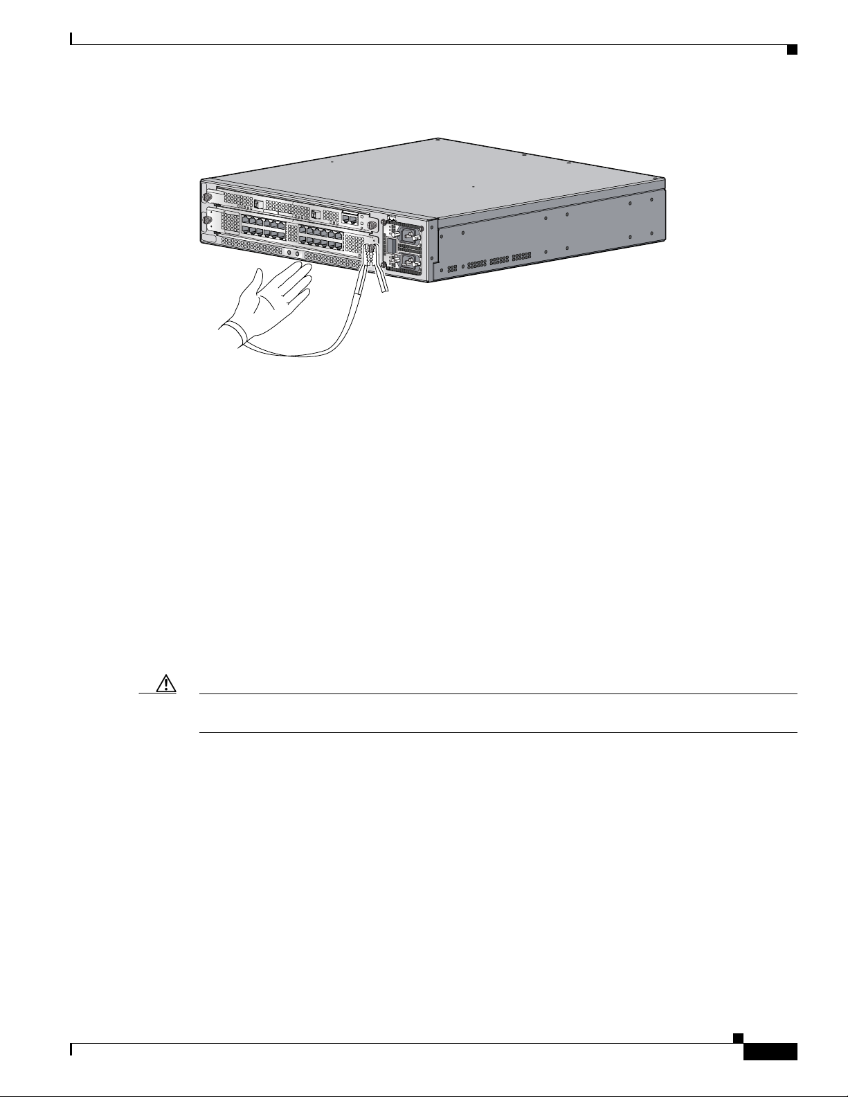
• Always use an ESD-preventive wrist strap and ensure that the strap makes adequate contact with
your skin.
• Attach an ESD-preventive wrist strap to your wrist and to the chassis; or to a bare metal surface.
(See Figure 1.)
• The ESD-preventive wrist strap protects equipment from ESD voltages on the body only; ESD
voltages on clothing can still cause damage to electronic components.
Caution For safety, periodically check the resistance value of the ESD-preventive wrist strap. The resistance
measurement should be between 1 and 10 megohms.
Preventing Electrostatic Discharge
Electrostatic discharge (ESD) damage can cause complete or intermittent equipment failures. Cisco
recommends using an ESD-preventive strap when you handle a router or one of its components.
Electromagnetic interference (EMI) shielding is an integral component of the router.
Following are guidelines for preventing ESD damage:
• Always use an ESD-preventive wrist or ankle strap and ensure that it makes good skin contact.
Connect the equipment end of the connection cord to bare metal on the router chassis. (See
Figure 1.)
Disconnect Device Warnings
4
78-13101-02
Page 5
Rack Mounting Guidelines
Figure 1 Attaching an ESD-Preventive Strap
U
R
E
R
IE
T
H
IV
R
K
T
P
T
R
P
C
A
S
A
X
A
S
R
C
R
A
W
P
RE
S
ET
S
U
C
A
P
O
NS
T
M
IL
O
LE
A
E
S
A
C
O
AU
T
K
M
F
X
R
R
E
D
E
E
T
R
V
S
W
A
O
Y
O
C
D
C
S
O
P
K
O
T
F
L
I
A
)
F
S
G
(
P
D
B
E
R
V
M
A
I
C
0
T
0
C
1
/A
K
N
I
L
IL
A
F
R
D
E
R
W
A
O
A
C
C
O
P
K
D
C
O
K
O
T
F
D
O
N
N
O
T R
EM
OV
O
R
E
IN
S
E
R
T
C
A
B
W
LE
ITH
S
TH
E
PO
W
E
R
O
N
IN
P
U
T
1
00
-2
00
- 5
0
/6
0
H
z
2
-5
A
•
Avoid contact between the component and clothing. The wrist strap protects the component only
from ESD voltages on the body; ESD voltages on clothing can still cause damage.
57849
Rack Mounting Guidelines
Before installing the Cisco 10720 Internet Router in a 19-inch EIA, 23/24-inch EIA or ETSI equipment
rack, consider the following general rack-mounting guidelines:
• Ventilation Guidelines, page 5
• Rack Mounting Clearance Guidelines, page 7
• Multiple Routers in a Rack Maintenance Guidelines, page 7
Ventilation Guidelines
Caution The fan assembly is located in the back of the router chassis. Air flow in the front and back of the router
should not be blocked.
The following section provides information and guidelines to provide adequate ventilation for the
Cisco 10720 Internet Router:
• Install the chassis in an enclosed rack only if the rack has adequate ventilation or an exhaust fan; use
an open rack when possible.
• A ventilation system that is too powerful in an enclosed rack can also prevent cooling by creating
negative air pressure around the router and redirecting the air away from the air intake vent. If
necessary, operate the router with the rack door open or in an open rack.
• Make sure the air baffle located between the fan assembly and power supply is properly seated to
assist in cooling the router.
78-13101-02
Rack Mounting Guidelines
5
Page 6
Rack Mounting Guidelines
Note To check the air baffle, the cover of the router chassis must be removed. For instructions on
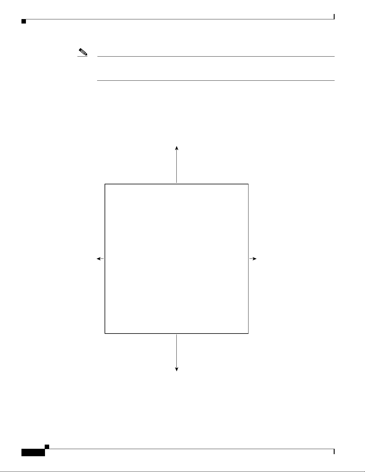
See Figure 2 for the ventilation requirements of the Cisco 10720 Internet Router.
Figure 2 Ventilation Requirements for Cisco 10720 Internet Router
removing the chassis cover, refer to Chapter 5, “Maintaining the Cisco 10720 Internet Router”,
in the Cisco 10720 Internet Router Installation and Configuration Guide.
• Check equipment located near the bottom of the rack as it can generate excessive heat that is drawn
upward and into the intake ports of equipment above, leading to possible overheat conditions.
6 in.
(15.24 cm)
0.75 in.
(1.9 cm)
6 in.
(15.24 cm)
0.75 in.
(1.9 cm)
57879
Ventilation Guidelines
6
78-13101-02
Page 7
Rack Mounting Clearance Guidelines
The rack-mounting hardware included with the Cisco 10720 Internet Router is suitable for most 19-inch
EIA, 23- or 24-inch EIA or ETSI equipment racks or telco-style racks.
The following are rack-mounting guidelines for the Cisco 10720 Internet Router:
• If you use a telco-style rack, be sure that the rack is bolted to the floor. The router mounts to the two
rack posts and the rest of the router is cantilevered off of the posts. (See Figure 12.)
• Some telco-style racks are secured to ceiling brackets, if necessary, because of the weight of the
equipment in the rack. Make sure that the rack you are installing the Cisco 10720 Internet Router in
is secure.
Note Warm air exhausts out the back of the router by drawing cool air in through vents located on the front of
the router chassis. Allow sufficient air flow by maintaining 6 inches (15.24 cm) of clearance at both the
inlet and exhaust openings on the router and 0.75 inches (19.1 mm) on each side of the router chassis.
(See Figure 2.)
Multiple Routers in a Rack Maintenance Guidelines
Rack Mounting Guidelines
The Cisco 10720 Internet Router is 17.50 (44.45 cm) W x 3.45 (8.76 cm) H (2 RU) x 18.25 inches (46.36
cm) D. When the cable-management tray is installed the router is 21.80 inches (55.37 cm) D. When
placing multiple routers in a rack, ensure there is sufficient ventilation to accommodate each router.
The heated exhaust air from other equipment can enter the inlet air vents and cause an overtemperature
condition inside the router.
• Install and use the cable-management system included with the router to keep cables organized and
out of the way of line cards and power supply.
• Ensure that cables from other equipment do not interfere with access to the cards and LEDs located
in the front of the router.
• When mounting the router in a rack, be sure to use all of the screws provided to secure the router to
the rack posts.
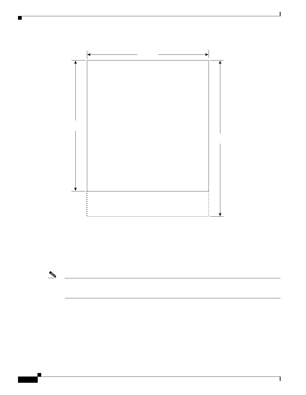
Figure 3 illustrates the outer dimensions of the Cisco 10720 Internet Router.
78-13101-02
Rack Mounting Clearance Guidelines
7
Page 8
Cisco 10720 Internet Router Setup Checklist
Figure 3 Cisco 10720 Internet Router Outer Dimensions (Top View
17.50 in.
(44.45 cm)
18.25 in.
(46.36 cm)
Cable management bracket
Chassis
Height = 2 RU
Cisco 10720 Internet Router Setup Checklist
Before you install your Cisco 10720 Internet Router, verify the following:
21.80 in.
(55.37 cm)
57878
Note The “Environmental Safety Guidelines” section in Chapter 2 of the Cisco 10720 Internet Router
Installation and Configuration Guide provides important information on environmental considerations
and requirements.
Ensure that you have considered the following before you install the router:
• Fan assembly exhaust vents should not be blocked.
• The front of router should not be blocked. Air flow intake is located on the front of the router.
• 24 inches (61 cm) of clearance in front of the Cisco 10720 Internet Router may be needed for
working with line cards, power supplies, attaching network interface cards (NICs) or other
components.
• Location is temperature-controlled, air-conditioned and dust-free.
Cisco 10720 Internet Router Setup Checklist
8
78-13101-02
Page 9

• Power cables and power supplies have been checked for compatibility with your power service.
• Labels on the equipment have been checked to ensure that the power service at your site is suitable
for the Cisco 10720 Internet Router.
• AC- or DC-power source voltage receptacles are easy to reach.
Installing the Cable-Management System
Perform the following steps to install the cable-management system:
Step 1 Power down your router. (Refer to Chapter 5, “Maintaining the Cisco 10720 Internet Router”, in the
Cisco 10720 Internet Router Installation and Configuration Guide.)
Step 2 Attach an ESD-preventive wrist strap to your wrist and to the router; or to a bare metal surface. (See
“Preventing Electrostatic Discharge” section on page 4.)
Step 3 Attach the cable-management tray to the router using four of the 3.5 mm x 6 mm screws that are shipped
with the router. Secure the cable-management tray by two screws on each side of the router chassis. (See
Figure 4.)
Installing the Cable-Management System
Figure 4 Attaching Cable-Management Tray
U
R
E
R
IE
T
H
IV
R
K
T
P
T
R
P
C
A
S
A
X
A
S
R
C
R
A
W
P
R
E
S
E
T
S
P
TAU
S
M
IL
O
L
E
A
U
X
E
T
R
D
E
R
V
A
O
C
SY
ARD FAIL
C
LINK/ACTIVE (G)
A
F
D
R
W
A
O
C
P
D
O
O
R
W
IT
H
A
S
A
C
O
K
M
F
R
E
TE
S
W
O
D
C
O
P
K
O
T
F
100 MBPS
IL
R
E
A
C
O
K
D
C
O
K
O
T
F
N
N
O
T
R
E
M
O
V
E
IN
S
E
R
T
C
A
B
L
E
S
T
H
E
P
O
W
E
R
O
N
IN
P
U
T
1
0
0
-2
0
0
- 5
0
/6
0
H
z
2
-5
A
66296
Step 4
C
O
N
Connect all interface cables to their respective ports if necessary.
Step 5 Separate the interface cables and lead them out the sides of the cable-management tray. Use cable ties
to keep the cables together. (See Figure 5.)
Note To avoid damage to the cables, avoid excessive bending.
78-13101-02
Installing the Cable-Management System
9
Page 10

Installing the Cable-Management System
Figure 5 Managing Router Cables with the Cable-Management Tray
ACTIVE
CARRIER
RX PKT
WRAP
PASS THRU
R
E
S
E
T
C
O
N
S
O
L
E
A
C
A
O
U
K
X
OVERTEMP
CARD FAIL
D
C
SYSTEM STAUS
O
POWER
K
O
T
F
IL
A
)
S
F
P
(G
D
B
E
R
A
C
TIV
00 M
C
1
/A
K
LIN
A
C
CARD FAIL
O
POWER
K
D
C
O
K
O
T
F
DON NOT REMOVE
OR INSERT CABLES
WITH THE POWER ON
IN
P
U
T
1
0
0-2
0
0
- 5
0
/6
0
Hz
2
-5
A
57749
Step 6
Use cable ties to secure the cables to the rack to keep the wires from accidental bends or breaks. (See
Figure 6.)
Figure 6 Cable-Management Installed in the Rack
U
R
E
R
IE
T
H
IV
R
K
T
P
T
R
P
C
A
S
A
X
A
S
R
C
R
A
W
Step 7
P
Power up the router. (Refer to Chapter 5, “Maintaining the Cisco 10720 Internet Router”, in the
R
E
S
E
T
S
U
C
A
P
O
N
T
S
M
IL
O
L
A
E
E
S
A
C
O
A
T
K
U
M
F
X
R
R
E
D
E
E
T
R
V
S
W
A
O
Y
O
C
D
C
S
O
P
K
O
T
F
L
I
A
)
F
S
G
(
P
D
B
E
R
V
M
A
I
C
0
T
0
C
1
A
/
K
N
I
L
IL
A
F
R
D
E
R
W
A
O
A
C
C
O
P
K
D
C
O
K
O
T
F
D
O
N
N
O
T
R
E
M
O
O
V
R
E
I
N
S
E
R
T
C
A
B
W
L
IT
E
H
S
T
H
E
P
O
W
E
R
O
N
IN
P
U
T
1
0
0
-2
0
0
-
5
0
/6
0
H
z
2
-5
A
57844
Cisco 10720 Internet Router Installation and Configuration Guide.)
Step 8 (Optional) Using a Number 1 Phillips screwdriver, attach the cable-management cover with four screws
that secure the cable-management cover to the router. (See Figure 7.)
10
Figure 7 Installing the Cable-Management Cover
Installing the Cable-Management System
IER
ACTIVE
RAP
CARR
RX PKT
W
PASS THRU
CISCO 10720 INTERNET ROUTER
CONSOLE
RESET
US
P
AC
STA
O
AUX
OVERTEM
CARD FAIL
CARD FAIL
LINK/ACTIVE (G)
CAR
O
W
WER
SYSTEM
PO
100 MBPS
D FAIL
ER
POW
DON
NOT REM
R INSERT CABLES
ITH THE POW
OVE
ER ON
K
DC
O
K
O
TF
A
C O
K
DC O
K
O
TF
INPUT 100-200- 50/60Hz 2-5A
57748
78-13101-02
Page 11

Removing the Cable-Management System
Perform the following steps to remove the cable-management system:
Step 1 Attach an ESD-preventive wrist strap to your wrist and to the router; or to a bare metal surface. (See the
“Preventing Electrostatic Discharge” section on page 4.)
Step 2 Verify that all cables are safely secured before detaching the cable-management cover. If the
cable-management cover is not installed go to Step 5.
Step 3 Remove the cable-management cover from the router by removing the four screws that secure the
cable-management cover to the router. (See Figure 8.)
Figure 8 Removing the Cable-Management Cover
AP
ACTIVE
CARRIER
RX PKT
ASS THRU
WR
P
RESET
CONSOLE
P
M
STAUS
AUX
RTE
EM
WER
OVE
CARD FAIL
SYST
PO
CARD FAIL
100 MBPS
LINK/ACTIVE (G)
IL
R
WE
CARD FA
PO
DON NOT REMOVE
OR INSERT CABLES
WITH THE POW
CISCO 10720 INTERNET ROUTER
Removing the Cable-Management System
AC OK
D
C OK
O
TF
AC
O
K
DC OK
O
TF
ER ON
IN
PU
T 100-200- 50/60Hz 2-5A
66299
Caution To avoid accidental damage to router cables or card ports, it is recommended that all cables are removed
before removing the cable-management tray.
Step 4 Remove cable ties and separate the interface cables if needed to lead the cables into the inside of the
cable-management tray. (See Figure 6.)
Step 5 Detach the cable-management tray from the router by removing the two 3.5mm x 6mm screws on each
side of the router. (See Figure 9.)
Figure 9 Removing the Cable-Management Tray
ACTIVE
CARRIER
RX PKT
WRAP
PASS THRU
R
ES
ET
CO
NSO
LE
AU
X
OVERTEMP
L
C
IN
CARD FAIL
CARD FAIL
R
A
/A
K
W
SYSTEM STAUS
POWER
IL
A
F
(G
D
E
IV
T
0
C
1
POWER
D
O
N
O
R
IN
IT
H
T
AC OK
DC OK
OTF
)
S
P
B
M
0
AC OK
DC OK
OTF
N
O
T
R
E
M
O
V
E
S
E
R
T
C
A
B
L
E
S
H
E
P
O
W
E
R
O
N
INPUT 100-200- 50/60Hz 2-5A
66297
78-13101-02
Removing the Cable-Management System
11
Page 12

Rack Mounting the Router
Rack Mounting the Router
This section demonstrates how to mount the Cisco 10720 Internet Router on an equipment rack, wall, or
desktop. The Cisco 10720 Internet Router comes with three sets of brackets for rack mounting, one set
of brackets for wall mounting and four rubber foot pads for desk mounting.
Check the clearance around the router before installation. (See the “Rack Mounting Guidelines” section
on page 5.)
Note Warm air exhausts out the back side of the router by drawing cool air in through vents located on the
front of the router chassis. Allow sufficient air flow by maintaining 6 inches (15.24 cm) of clearance at
both the inlet and exhaust openings on the router and.75 inches (19.1 mm) on each side of the router
chassis. (See Figure 2.)
The following rack mounting steps describe how to mount the router on a 19-inch, 23- and 24-inch, or
ETSI rack:
Step 1 Choose the appropriate rack mounts to fit your rack. (See Figure 10.)
Figure 10 Cisco 10720 Internet Router Rack Mounts
19 inch
ETSI
23/24 inch
57664
Step 2 Attach an ESD-preventive wrist strap to your wrist and to the router chassis; or to a bare metal surface.
(See the “Preventing Electrostatic Discharge” section on page 4.)
Step 3 Turn the Cisco 10720 Internet Router so that the front panel is facing you. The fans are in the back of
the router. (See Figure 11.)
Step 4 Align the mounting brackets to the right and left side of the router. Use a Number 1 Phillips screwdriver
with the screws that are supplied in the accessory kit to attach the mounting brackets to the router.
12
Step 5 Install the Cisco 10720 Internet Router in a rack with the front panel forward. (See Figure 11.)
Rack Mounting the Router
78-13101-02
Page 13

Rack Mounting the Router
Step 6 Align the mounting brackets on the Cisco 10720 Internet Router to the holes in the rack. The mounting
brackets can be installed on the router in the following ways:
• For a front rack mount, align the mounting brackets to the holes in the right and left sides of the
router that are closest to the front of the router. (See Figure 11.)
• For a middle rack mount, align the mounting brackets to the holes in the right and left sides of the
router that are in the center of the side panels.
• For a rear rack mount, align the mounting brackets to the holes in the right and left sides of the router
that are closest to the back of the router.
Figure 11 Installing Rack Mounts
U
R
E
R
E
I
T
V
H
I
R
K
T
T
P
R
P
C
A
S
A
X
A
S
R
C
R
A
W
P
R
E
SE
T
S
U
C
A
P
O
N
T
L
S
M
I
O
LE
S
AC OK
E
A
A
T
U
M
F
X
R
R
E
D
E
E
T
R
V
S
W
A
O
Y
O
C
DC OK
S
P
OTF
L
I
A
)
F
S
G
(
P
D
B
E
R
V
M
A
I
C
0
T
0
C
1
A
/
K
N
I
L
IL
A
F
R
D
E
R
W
A
O
AC OK
C
P
DC OK
OTF
D
O
N
N
O
T
R
E
M
O
O
V
R
E
IN
S
E
R
T
C
A
W
B
L
I
T
E
H
S
T
H
E
P
O
W
E
R
O
N
INPUT 100-200- 50/60Hz 2-5A
19 inch
Step 7
U
R
E
R
IE
T
V
H
I
R
K
T
T
P
R
P
C
A
S
A
X
A
S
R
C
R
A
W
P
R
ES
E
T
S
U
C
A
P
O
N
T
L
S
M
I
O
LE
S
AC OK
E
A
A
T
F
U
M
X
R
R
E
D
E
E
T
R
V
S
W
A
O
Y
O
C
DC OK
S
P
OTF
L
I
A
)
F
S
G
(
P
D
B
E
R
V
M
A
I
C
0
T
0
C
1
A
/
K
N
I
L
L
I
A
F
R
D
E
R
W
A
O
AC OK
C
P
DC OK
OTF
D
O
N
N
O
T
R
E
M
O
O
V
R
E
IN
S
E
R
T
C
A
W
B
L
IT
E
H
S
T
H
E
P
O
W
E
R
O
N
INPUT 100-200- 50/60Hz 2-5A
ETSI
U
R
E
R
E
I
T
V
H
I
R
K
T
P
T
R
P
C
A
S
A
X
A
S
R
C
R
A
W
P
R
E
S
E
T
S
U
C
A
P
O
N
T
L
S
M
I
O
LE
AC OK
E
S
A
A
T
F
U
M
X
R
R
E
D
E
E
T
R
V
S
W
A
O
Y
O
C
DC OK
S
P
OTF
L
I
A
)
F
S
G
(
P
D
B
E
R
V
M
A
I
C
0
T
0
C
1
A
/
K
N
I
L
L
I
A
F
R
D
E
R
W
A
O
AC OK
C
P
DC OK
OTF
D
O
N
N
O
T
R
E
M
O
O
V
R
E
I
N
S
E
R
T
C
A
W
B
L
IT
E
H
S
T
H
E
P
O
W
E
R
O
N
INPUT 100-200- 50/60Hz 2-5A
57751
23/24 inch
Use a Number 1 Phillips screwdriver to attach four screws to attach each side of the router chassis to the
rack. (See Figure 12.)
78-13101-02
Rack Mounting the Router
13
Page 14

Rack Mounting the Router
Figure 12 Attaching the Router to the 19-Inch Rack (Front Panel Forward)
ACTIVE
CARRIER
RX PKT
WRAP
PASS THRU
Wall Mounting the Router
R
E
S
E
T
C
P
O
N
S
O
L
AC
E
STAUS
OK
A
U
X
OVERTEM
CARD FAIL
DC
SYSTEM
OK
POWER
O
TF
L
I
A
)
F
S
G
(
P
D
B
E
R
V
M
A
I
C
0
T
0
C
1
A
/
K
IN
L
AC O
CARD FAIL
POWER
K
D
C O
K
O
TF
DON NOT REMOVE
OR INSERT CABLES
WITH
THE
POWER ON
INPUT 100-200- 50/60Hz 2-5A
57665
The wall mount brackets must be mounted on a minimum 5/8” (15.9 mm) wallboard gypsum or
equivalent with twelve 1 1/4” No. 10 screws or equivalent (M5 x 31.8 mm).
Caution The front and back panels of the Cisco 10720 Internet Router require at least 6 inches clearance away
from the wall or other items that can block proper air flow. The side panel requires 1 inch clearance away
from the wall or other items that can block proper air flow. The top and bottom of the router chassis do
not require any specific clearance.
The following steps illustrate hot to set up a proper and secure wall mount for the router. These steps
ensure adequate ventilation is available at all times. A Number 1 Phillips screwdriver is required to
perform the following procedure:
Step 1 Locate the two 17.25-inch (43.82) long metal mounts; twelve 1 1/4-inch No. 10 (3.18 cm) screws, and
ten screws for attaching the mount to the router chassis, included in the accessories kit.
Note Ve rif y tha t no electrical, heating, or plumbing should be located behind the drilling location.
Step 2 Predrill 12 holes on the mounting surface. The holes on the side of the router chassis are 3.23 inches (8.2
cm) apart. The side to side distance is 18.35 inches (46.6 cm). (See Figure 13.)
14
Wall Mounting the Router
78-13101-02
Page 15

Figure 13 Predrilled 12 holes
3.23 in.
(8.2 cm)
18.35 in.
(46.6 cm)
Rack Mounting the Router
57851
Step 3
Attach an ESD-preventive wrist strap to your wrist and to the router chassis; or to a bare metal surface.
(See the “Preventing Electrostatic Discharge” section on page 4.)
Step 4 Attach the wall mount brackets to the side of the chassis using five screws on each side. (See Figure 14.)
78-13101-02
Wall Mounting the Router
15
Page 16

Rack Mounting the Router
Figure 14 Attaching Wall Mount Brackets to Router Chassis
57853
O
T
IN
F
D
O
C
K
O
T
IN
F
D
O
C
K
Note The Cisco 10720 Internet Router must be mounted with the right side down (horizontal) when it is
mounted on the wall. The right side of the router is the side where the power supply is located.
Step 5 Match the holes in the wall mount brackets to the predrilled holes on the mounting surface and attach
the brackets using the twelve 1 1/4-inch screws to the wall. (See Figure 15.)
Note When mounted on the wall, make sure the power receptacles are at the bottom of the router. (See
Figure 15.)
16
Wall Mounting the Router
78-13101-02
Page 17

Figure 15 Rack Wall Mount
Obtaining Technical Assistance
O
T
IN
F
D
O
C
K
O
T
IN
F
D
O
C
K
Obtaining Technical Assistance
Cisco provides Cisco.com as a starting point for all technical assistance. Customers and partners can
obtain documentation, troubleshooting tips, and sample configurations from online tools. For Cisco.com
registered users, additional troubleshooting tools are available from the TAC website.
Technical assistance information is presented in the following sections:
• Contacting Cisco, page 17
• Technical Assistance Center, page 18
• World Wide Web, page 19
Contacting Cisco
57666
78-13101-02
Cisco provides Cisco.com as a starting point for all technical assistance. Customers and partners can
obtain documentation, troubleshooting tips, and sample configurations from online tools. For Cisco.com
registered users, additional troubleshooting tools are available from the TAC website.
Obtaining Technical Assistance
17
Page 18

Obtaining Technical Assistance
Cisco.com
Cisco.com is the foundation of a suite of interactive, networked services that provides immediate, open
access to Cisco information and resources at anytime, from anywhere in the world. This highly
integrated Internet application is a powerful, easy-to-use tool for doing business with Cisco.
Cisco.com provides a broad range of features and services to help customers and partners streamline
business processes and improve productivity. Through Cisco.com, you can find information about Cisco
and our networking solutions, services, and programs. In addition, you can resolve technical issues with
online technical support, download and test software packages, and order Cisco learning materials and
merchandise. Valuable online skill assessment, training, and certification programs are also available.
Customers and partners can self-register on Cisco.com to obtain additional personalized information and
services. Registered users can order products, check on the status of an order, access technical support,
and view benefits specific to their relationships with Cisco.
To access Cisco.com, go to the following website:
http://www.cisco.com
Technical Assistance Center
The Cisco TAC website is available to all customers who need technical assistance with a Cisco product
or technology that is under warranty or covered by a maintenance contract.
Contacting TAC by Using the Cisco TAC Website
If you have a priority level 3 (P3) or priority level 4 (P4) problem, contact TAC by going to the TAC
website:
http://www.cisco.com/tac
P3 and P4 level problems are defined as follows:
• P3—Your network performance is degraded. Network functionality is noticeably impaired, but most
business operations continue.
• P4—You need information or assistance on Cisco product capabilities, product installation, or basic
product configuration.
In each of the above cases, use the Cisco TAC website to quickly find answers to your questions.
To register for Cisco.com, go to the following website:
http://www.cisco.com/register/
If you cannot resolve your technical issue by using the TAC online resources, Cisco.com registered users
can open a case online by using the TAC Case Open tool at the following website:
http://www.cisco.com/tac/caseopen
Contacting TAC by Telephone
If you have a priority level 1(P1) or priority level 2 (P2) problem, contact TAC by telephone and
immediately open a case. To obtain a directory of toll-free numbers for your country, go to the following
website:
http://www.cisco.com/warp/public/687/Directory/DirTAC.shtml
Technical Assistance Center
18
78-13101-02
Page 19

P1 and P2 level problems are defined as follows:
• P1—Your production network is down, causing a critical impact to business operations if service is
not restored quickly. No workaround is available.
• P2—Your production network is severely degraded, affecting significant aspects of your business
operations. No workaround is available.
World Wide Web
You can access the most current Cisco documentation on the World Wide Web at the following sites:
• http://www.cisco.com
• http://www-china.cisco.com
• http://www-europe.cisco.com
Related Documentation
The following section provides some reference material out of the Cisco.com library that may be useful
for configuring and maintaining the Cisco 10720 Internet Router:
• Cisco 10720 Internet Router Installation and Configuration Guide
Related Documentation
• Regulatory Compliance and Safety Information for the Cisco 10720 Internet Router
Obtaining Documentation
The following sections provide sources for obtaining documentation from Cisco Systems. Access to
documentation is presented in the following sections:
• Documentation CD-ROM, page 19
• Ordering Documentation, page 19
• Documentation Feedback, page 20
Documentation CD-ROM
Cisco documentation and additional literature are available in a CD-ROM package, which ships with
your product. The Documentation CD-ROM is updated monthly and might be more current than printed
documentation. The CD-ROM package is available as a single unit or as an annual subscription.
Ordering Documentation
Cisco documentation is available in the following ways:
78-13101-02
• Registered Cisco Direct Customers—Can order Cisco Product documentation from the Networking
Products MarketPlace:
http://www.cisco.com/cgi-bin/order/order_root.pl
World Wide Web
19
Page 20

Electromagnetic Compliance
• Registered Cisco.com users—Can order the Documentation CD-ROM through the online
Subscription Store:
http://www.cisco.com/go/subscription
• Nonregistered Cisco.com users—Can order documentation through a local account representative
by calling Cisco:
–
408 526-7208
–
North America—800 555-NETS(6387)
Documentation Feedback
If you are reading Cisco product documentation on the World Wide Web, you can submit technical
comments electronically. Click Feedback in the toolbar and select Documentation. After you complete
the form, click Submit to send it to Cisco.
You can e-mail your comments to bug-doc@cisco.com.
To submit your comments by mail, use the response card behind the front cover of your document, or
write to the following address:
Attn. Document Resource Connection
Cisco Systems, Inc.
170 West Tasman Drive
San Jose, CA 95134-9883
We appreciate your comments.
Electromagnetic Compliance
Safety compliance information is presented in the following sections:
• Electromagnetic Compatibility Regulatory Statements, page 20
• Site Wiring Distance and Interference Guidelines, page 23
Electromagnetic Compatibility Regulatory Statements
FCC Class A Compliance
This equipment has been tested and found to comply with the limits for a Class A digital device, pursuant
to part 15 of the FCC rules. These limits are designed to provide reasonable protection against harmful
interference when the equipment is operated in a commercial environment. This equipment generates,
uses, and can radiate radio-frequency energy and, if not installed and used in accordance with the
instruction manual, may cause harmful interference to radio communications. Operation of this
equipment in a residential area is likely to cause harmful interference, in which case users will be
required to correct the interference at their own expense.
Modifying the equipment without Cisco’s authorization may result in the equipment no longer
complying with FCC requirements for Class A digital devices. In that event, your right to use the
equipment may be limited by FCC regulation and you may be required to correct any interference to
radio or television communication at your own expense.
20
Documentation Feedback
78-13101-02
Page 21

CISPR 22
Electromagnetic Compliance
You can determine whether your equipment is causing interference by turning it off. If the interference
stops, it was probably caused by the Cisco equipment or one of its peripheral devices. If the equipment
causes interference to radio or television reception, try to correct the interference by using one or more
of the following measures:
• Turn the television or radio antenna until the interference stops.
• Move the equipment to one side or the other of the television or radio.
• Move the equipment farther away from the television or radio.
• Plug the equipment into an outlet that is on a different circuit from the television or radio. (In other
words, make certain the equipment and the television or radio are on circuits controlled by different
circuit breakers or fuses.)
Warning
Note For CISPR 22 class B, the use of shielded (i.e. screened) CAT5 or equivalent Ethernet cable is required.
Note This apparatus complies with EN55022 class B conducted emissions requirements on AC main with
This is a class A product. In a domestic environment, this product may cause radio interference, in
which case, the user may be required to take adequate measures.
unshielded or shielded CAT5 Ethernet cabling (i.e. does not require the use of shielded Ethernet cable
to meet this requirement.)
Canada
English Statement of Compliance
This class A digital apparatus complies with Canadian ICES-003.
French Statement of Compliance
Cet appareil numérique de la classe A est conforme à la norme NMB-003 du Canada.
Europe (EU)
This apparatus complies with EN55022 Class A and EN55024 standards when used as ITE/TTE
equipment, and EN 300 386-2 (EN55022 class B with shielded CAT5 Ethernet cable, non-central office
equipment) for Telecommunications Network Equipment (TNE).
Hungarian Class A Warning
Figyelmeztetés a felhasználói kézikönyv számára:
78-13101-02
Electromagnetic Compatibility Regulatory Statements
21
Page 22

Electromagnetic Compliance
Ez a berendezés “A” osztályú termék, felhasználására és üzembe helyezésére a magyar EMC “A”
osztályú követelményeknek (MSZ EN 55022) megfelelõen kerülhet sor, illetve ezen “A” osztályú
berendezések csak megfelelõ kereskedelmi forrásból származhatnak, amelyek biztosítják a megfelelõ
speciális üzembe helyezési körülményeket és biztonságos üzemelési távolságok alkalmazását.
This equipment is a class A product and should be used and installed properly according to the
Hungarian EMC Class A requirements (MSZEN55022). The Class A equipment are derived for typical
commercial establishments for which special conditions of installation and protection distance are used.
Taiwan Class A Warning
This is a class A product. In a domestic environment this product may cause radio interference in which
case you may be required to take adequate measures.
Note Bureau of Standards, Metrology and Inspection (BSMI) product approval license number is on the
product label outside the system enclosure.
Japan VCCI Class A
This is a Class A product based on the standard of the Voluntary Control Council for Interference by
Information Technology Equipment (VCCI). If this equipment is used in a domestic environment, radio
disturbance may arise. When such trouble occurs, the user may be required to take corrective actions.
Korean Class A Warning
22
Class A device. This device is registered for EMC requirements for industrial use. The seller or buyer
should be aware of this. If this type was sold or purchased by mistake, it should be replaced with a
residential-use type.
Electromagnetic Compatibility Regulatory Statements
78-13101-02
Page 23

Site Wiring Distance and Interference Guidelines
This section offers site wiring guidelines for setting up the site plant wiring and cabling. When planning
the location of the new system, consider the following:
• Electromagnetic Interference, page 23
• Distance Limitations for Signaling and Unshielded Conductors, page 23
Electromagnetic Interference
Electromagnetic interference can occur between the field and the signals on the wires when the wires are
run for any significant distance. This fact has two
• Poor wiring practice can result in radio interference emanating from the plant wiring.
• Strong EMI, especially when it is caused by lightning or radio transmitters, can destroy and/or cause
interference with the signal drivers and receivers in the Cisco 10720 Internet Router, and can create
an electrical hazard by conducting power surges through lines and into equipment.
Note To predict and remedy strong EMI, consult experts in radio frequency interference (RFI).
implications for the construction of plant wiring:
Translated Safety Warnings
A good quality twisted pair cable or shielded twisted pair cable helps limit radiation and noise induced
into the cable minimizing,
• Potential for radio interference.
• Potential for interference with the data transmission.
Distance Limitations for Signaling and Unshielded Conductors
Give special consideration to the effect of a lightning strike in the site vicinity if wires exceed
recommended distances, or if wires pass between buildings. The electromagnetic pulse (EMP) caused
by lightning or other high-energy phenomena can easily couple enough energy into unshielded
conductors to destroy electronic devices.
Provide a properly grounded and shielded environment. Consider electrical surge suppression issues by
addressing the following items:
• Potential surge sources
• Distance
Caution Splicing can degrade cable performance.
Translated Safety Warnings
78-13101-02
Safety warnings appear throughout this publication in procedures that, if performed incorrectly, may
harm you. A warning symbol precedes each warning statement. The following paragraph is an example
of a safety warning. It identifies the warning symbol and associates it with a bodily injury hazard. The
remaining paragraphs in this section are translations of the initial safety warning.
Site Wiring Distance and Interference Guidelines
23
Page 24

Translated Safety Warnings
Note For a complete list of translated safety warnings, read the Regulatory Compliance and Safety
Information for the Cisco 10720 Internet Router document that accompanies your
Cisco 10720 Internet Router. We recommend that you read and understand the safety warnings and
guidelines before installing, configuring or maintaining the router.
Table 1 Translated Safety Warnings
Warning
Waarschuwing
Varoitus
Attention
This warning symbol means danger. You are in a situation that could cause
bodily injury. Before you work on any equipment, be aware of the hazards
involved with electrical circuitry and be familiar with standard practices for
preventing accidents. (To see translations of the warnings that appear in this
publication, refer to the appendix “Translated Safety Warnings” in the
installation guide that accompanied this device.)
Dit waarschuwingssymbool betekent gevaar. U verkeert in een situatie die
lichamelijk letsel kan veroorzaken. Voordat u aan enige apparatuur gaat
werken, dient u zich bewust te zijn van de bij elektrische schakelingen
betrokken risico’s en dient u op de hoogte te zijn van standaard maatregelen om
ongelukken te voorkomen. (Voor vertalingen van de waarschuwingen die in
deze publicatie verschijnen, kunt u het aanhangsel “Translated Safety
Warnings” (Vertalingen van veiligheidsvoorschriften) in de installatiegids die
bij dit toestel is ingesloten, raadplegen.
Tämä varoitusmerkki merkitsee vaaraa. Olet tilanteessa, joka voi johtaa
ruumiinvammaan. Ennen kuin työskentelet minkään laitteiston parissa, ota
selvää sähkökytkentöihin liittyvistä vaaroista ja tavanomaisista
onnettomuuksien ehkäisykeinoista. (Tässä julkaisussa esiintyvien varoitusten
käännökset löydät tämän laitteen mukana olevan asennusoppaan liitteestä
"Translated Safety Warnings" (käännetyt turvallisuutta koskevat varoitukset).)
Ce symbole d’avertissement indique un danger. Vous vous trouvez dans une
situation pouvant entraîner des blessures. Avant d’accéder à cet équipement,
soyez conscient des dangers posés par les circuits électriques et
familiarisez-vous avec les procédures courantes de prévention des accidents.
Pour obtenir les traductions des mises en garde figurant dans cette publication,
veuillez consulter l’annexe intitulée « Translated Safety Warnings » (Traduction
des avis de sécurité) dans le guide d’installation qui accompagne cet appareil.
24
Warnung
Translated Safety Warnings
Dieses Warnsymbol bedeutet Gefahr. Sie befinden sich in einer Situation, die zu
einer Körperverletzung führen könnte. Bevor Sie mit der Arbeit an irgendeinem
Gerät beginnen, seien Sie sich der mit elektrischen Stromkreisen verbundenen
Gefahren und der Standardpraktiken zur Vermeidung von Unfällen bewußt.
(Übersetzungen der in dieser Veröffentlichung enthaltenen Warnhinweise
finden Sie im Anhang mit dem Titel “Translated Safety Warnings” (Übersetzung
der Warnhinweise) in der diesem Gerät beiliegenden Installationsanleitung.)
78-13101-02
Page 25

Table 1 Translated Safety Warnings (continued)
Translated Safety Warnings
Avvertenza
Advarsel
Aviso
¡Advertencia!
Questo simbolo di avvertenza indica un pericolo. Si è in una situazione che può
causare infortuni. Prima di lavorare su qualsiasi apparecchiatura, occorre
conoscere i pericoli relativi ai circuiti elettrici ed essere al corrente delle
pratiche standard per la prevenzione di incidenti. La traduzione delle
avvertenze riportate in questa pubblicazione si trova nell’appendice,
“Translated Safety Warnings” (Traduzione delle avvertenze di sicurezza), del
manuale d’installazione che accompagna questo dispositivo.
Dette varselsymbolet betyr fare. Du befinner deg i en situasjon som kan føre til
personskade. Før du utfører arbeid på utstyr, må du være oppmerksom på de
faremomentene som elektriske kretser innebærer, samt gjøre deg kjent med
vanlig praksis når det gjelder å unngå ulykker. (Hvis du vil se oversettelser av
de advarslene som finnes i denne publikasjonen, kan du se i vedlegget
"Translated Safety Warnings" [Oversatte sikkerhetsadvarsler] i
installasjonsveiledningen som ble levert med denne enheten.)
Este símbolo de aviso indica perigo. Encontra-se numa situação que lhe poderá
causar danos fisicos. Antes de começar a trabalhar com qualquer equipamento,
familiarize-se com os perigos relacionados com circuitos eléctricos, e com
quaisquer práticas comuns que possam prevenir possíveis acidentes. (Para ver
as traduções dos avisos que constam desta publicação, consulte o apêndice
“Translated Safety Warnings” - “Traduções dos Avisos de Segurança”, no guia
de instalação que acompanha este dispositivo).
Este símbolo de aviso significa peligro. Existe riesgo para su integridad física.
Antes de manipular cualquier equipo, considerar los riesgos que entraña la
corriente eléctrica y familiarizarse con los procedimientos estándar de
prevención de accidentes. (Para ver traducciones de las advertencias que
aparecen en esta publicación, consultar el apéndice titulado “Translated
Safety Warnings,” en la guía de instalación que se acompaña con este
dispositivo.)
78-13101-02
Varning!
Denna varningssymbol signalerar fara. Du befinner dig i en situation som kan
leda till personskada. Innan du utför arbete på någon utrustning måste du vara
medveten om farorna med elkretsar och känna till vanligt förfarande för att
förebygga skador. (Se förklaringar av de varningar som förekommer i denna
publikation i appendix "Translated Safety Warnings" [Översatta
säkerhetsvarningar] i den installationshandbok som medföljer denna
anordning.)
Translated Safety Warnings
25
Page 26

Translated Safety Warnings
This document is to be used in conjunction with the documents listed in the Cisco 10720 Internet RouterInstallation and Configuration Guide.
CVP, the Cisco logo, and the Cisco Square Bridge logo are trademarks of Cisco Systems, Inc.; Changing the Way We Work, Live, Play, and Learn is a
ervice mark of Cisco Systems, Inc.; and Access Registrar, Aironet, BPX, Catalyst, CCDA, CCDP, CCIE, CCIP, CCNA, CCNP, CCSP, Cisco, the Cisco
ertified Internetwork Expert logo, Cisco IOS, Cisco Press, Cisco Systems, Cisco Systems Capital, the Cisco Systems logo, Cisco Unity,
nterprise/Solver, EtherChannel, EtherFast, EtherSwitch, Fast Step, Follow Me Browsing, FormShare, GigaDrive, HomeLink, Internet Quotient, IOS,
Phone, IP/TV, iQ Expertise, the iQ logo, iQ Net Readiness Scorecard, iQuick Study, LightStream, Linksys, MeetingPlace, MGX, Networking Academy,
etwork Registrar, Pack e t, PIX, ProConnect, ScriptShare, SMARTnet, StackWise, The Fastest Way to Increase Your Internet Quotient, and TransPath are
egistered trademarks of Cisco Systems, Inc. and/or its affiliates in the United States and certain other countries.
ll other trademarks mentioned in this document or Website are the property of their respective owners. The use of the word partner does not imply a
artnership relationship between Cisco and any other company. (0705R)
Copyright © 2003 Cisco Systems, Inc. All rights reserved.
26
Translated Safety Warnings
78-13101-02
 Loading...