

Page 1

Quick Start
Quick Start Guide for Cisco 1040 Sensor
1 Overview
2 Preparing to Connect Your Cisco 1040
3 Connecting Your Cisco 1040
4 Using Your Cisco 1040
5 Where to Go Next
6 Related Documentation
7 Technical Specifications
8 Regulatory Compliance and Safety Information for Your Cisco 1040
9 Obtaining Documentation
10 Documentation Feedback
11 Cisco Product Security Overview
12 Product Alerts and Field Notices
13 Obtaining Technical Assistance
14 Obtaining Additional Publications and Information
Page 2

1 Overview
This guide is designed to help you quickly set up and use your Cisco 1040 Sensor (Cisco 1040). A
Cisco 1040 is a shelf-top unit that connects to the network and obtains Power over Ethernet (PoE)
through a Cisco Catalyst switch. It is easy to connect your Cisco 1040. These sections explain what a
Cisco 1040 does and how it fits in with products in the Cisco Unified Communications Management
Suite:
• Cisco 1040s and Cisco Unified Service Monitor, page 2
• Cisco 1040s and Cisco Unified Operations Manager, page 2
Cisco 1040s and Cisco Unified Service Monitor
Cisco 1040s listen to Real-Time Transport Protocol (RTP) voice traffic on a Switch Port Analyzer
(SPAN) port that you must configure to mirror voice traffic on phone ports or voice VLANs.
Cisco 1040 calculates Mean Opinion Scores (MOS) and sends data at 60-second intervals to Cisco
Unified Service Monitor (Service Monitor), a product from the Cisco Unified Communications
Management Suite.
Service Monitor examines the MOS value and compares it against a user-specified threshold value for
the codec in use on the call. When MOS drops below the threshold, Service Monitor generates SNMP
traps and sends them to up to four recipients. A single Service Monitor can receive and analyze MOS
data from multiple Cisco 1040s. If you have more than one Service Monitor, you can configure
Cisco 1040s to fail over to a secondary service monitor. For more information, see User Guide for
Cisco Unified Service Monitor.
Cisco 1040s and Cisco Unified Operations Manager
You can use Cisco Unified Operations Manager (Operations Manager) to further analyze, display, and
act on the traps that Cisco 1040 generates. When configured as a trap recipient from Service Monitor,
Operations Manager generates service quality events, displays and tracks these events on a real-time
dashboard, and displays and stores event history. You can configure additional event settings on
Operations Manager that alert you to low MOS and to the occurrence of many service quality events
during a period of time. In addition, you can configure Operations Manager to send notifications by
e-mail, SNMP trap, and syslog message.
2
Page 3

2 Preparing to Connect Your Cisco 1040
This section describes tasks that you must perform the first time you set up your network to support
Cisco 1040 operations. If you have not already completed the following tasks, it is advisable to
complete them so that your Cisco 1040 becomes fully operational minutes after you connect it.
Install and Configure Cisco Unified Service Monitor
Instructions for completing these tasks are available in User Guide for Cisco Unified Service Monitor
and in Service Monitor online help. Using Service Monitor, perform the following tasks:
• Set up Service Monitor. Among other parameters, you will specify a TFTP server.
• Edit configuration files for Cisco 1040s.
Configure DHCP Server Option 150
Configure your DHCP server so that option 150 returns the IP address for the TFTP server and
provides an IP address, subnet mask, default gateway, and, optionally, a DNS server for a Cisco 1040.
If you would like to configure a Cisco router as a DHCP server, see the following URL.
http://www.cisco.com/en/US/tech/tk648/tk361/technologies_tech_note09186a0080114aee.shtml
(Optional) Configure DNS
If you are using DNS in your network, configure DNS entries for Cisco 1040s.
3 Connecting Your Cisco 1040
Note Be sure to read the “Regulatory Compliance and Safety Information for Your Cisco 1040”
section on page 13 before connecting your Cisco 1040.
Figure 1 shows the connections and indicators on the front panel of your Cisco 1040.
3
Page 4
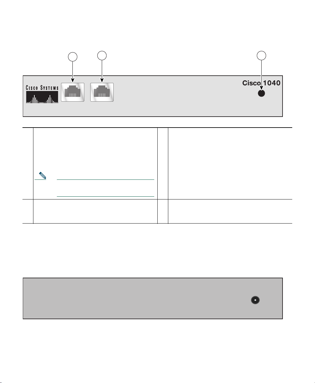
Figure 1 Cisco 1040 Cable Connections—Front Panel
1
10/100-1 10/100-2
1
10/100-1—Fast Ethernet port, standard RJ45
for connecting to the network and obtaining
2 3
POWER
3
Status indicator light—See Understanding the
Status Indicator Light, page 7.
inline power.
This port supports IEEE 802.3af standard
PoE.
Note This port does not support Cisco
prestandard PoE.
2
10/100-2—Fast Ethernet port, standard RJ45
—
—
for connecting to a SPAN or Remote SPAN
(RSPAN) destination port.
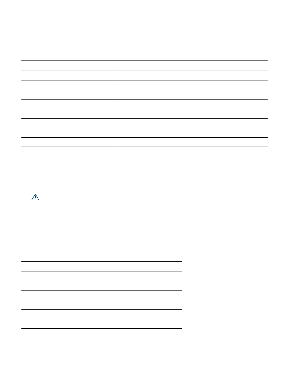
Figure 2 shows the connection on the rear panel of your Cisco 1040 for an external, separately
certified AC/DC power supply, for use if IEEE 802.3af-compliant PoE is not available. See Cable
Specifications, page 12.
141283
Figure 2 Cisco 1040 Cable Connections—Rear Panel
4
POWER
DC 5V 2.5A
141284
Page 5

Cisco 1040 Port Usage
This section provides a list of ports used by the Cisco 1040, for your reference.
Table 1 Cisco 1040 Port Usage
Protocol Port Number Service Name
UDP 53 DNS
UDP 67 and 68 DHCP
UDP 69 TFTP—Cisco 1040 uses TFTP to get a configuration file and
binary image file.
UDP 5666 Syslog—Cisco 1040 sends syslog messages to Service Monitor.
TCP 2000 SCCP—Cisco 1040 uses SCCP to communicate with Service
Monitor.
TCP 80 http—Cisco 1040 has a web-based user interface to view its
configuration
Selecting and Configuring a Cisco Catalyst Switch
To connect the Cisco 1040, you need a Cisco Catalyst switch with the following:
• A port that supports IEEE 802.3af standard Power over Ethernet (PoE).
• A port that is configured as a SPAN or RSPAN destination port for:
–
Ports to which phones are connected
–
VLANs
For information about configuring SPAN and RSPAN on Cisco Catalyst switches and modules,
see the following URL.
http://www.cisco.com/en/US/products/hw/switches/ps708/products_tech_note09186a008015c612.
shtml
Connecting the Cisco 1040 to the Cisco Catalyst Switch
Before you begin this procedure, see the regulatory compliance and safety information Statement
1001—Work During Lightning Activity, page 23.
5
Page 6

Step 1 Place the Cisco 1040 on top of the appropriate Cisco Catalyst switch.
Note The minimum height necessary to install the Cisco 1040 is 5.08 cm (2 in.). The
installation of the unit should not restrict the airflow around the device. When
operating the unit, ensure that no objects are placed on top of the unit.
Step 2 Connect a Category 5 straight-through cable from 10/100-1 (Fast Ethernet port 1) on the
Cisco 1040 to a port that supports IEEE 802.3af standard PoE on the Cisco Catalyst switch.
Step 3 Connect a Category 5 straight-through cable from 10/100-2 (Fast Ethernet port 2) on the
Cisco 1040 to a port that you have configured as a SPAN (or RSPAN) destination port on the
Cisco Catalyst switch.
Note Verify that this port on the switch is set up to mirror a VLAN or switch ports to which
phones are connected.
A startup process begins on the Cisco 1040. The status indicator on the front of the Cisco 1040
should flash amber, turn yellow, and then turn green. For more information, see Understanding
the Status Indicator Light, page 7.
4 Using Your Cisco 1040
After you have successfully connected your Cisco 1040, use Service Monitor to manage and configure
it. For example, you will use Service Monitor to specify the TFTP server to use, update configuration
files, set the time, and reset Cisco 1040s.
This section describes information that you can obtain directly from a Cisco 1040:
• Understanding the Status Indicator Light, page 7
• Using the Cisco 1040 Web Interface, page 8
Note Information obtained directly from a Cisco 1040 is also available in another form from
Service Monitor. Service Monitor displays the status of Cisco 1040s.
6
Page 7

Understanding the Status Indicator Light
The status indicator light on the front panel of a Cisco 1040 indicates what the Cisco 1040 is currently
doing. The following table lists the conditions that the status indicator light can be in and places the
conditions in startup sequence order.
Startup
Sequence
Number Status Indicator Light Cisco 1040 Condition
1 Orange solid Initial state
2 Yellow and flashing Obtained power from the switch and is doing one of the
following:
1. Obtaining an IP address using DHCP.
2. Accessing the TFTP server.
3. Requesting the configuration file and the binary
image file.
3 Yellow solid Registering to a service monitor.
4 Green solid or green and
flashing
Note If unable to register, the Cisco 1040 returns to
startup sequence number 2.
Registered to a service monitor:
• Green solid—Registered to the primary service
monitor.
• Green and flashing—Registered to a secondary
service monitor. When the primary service monitor
is available again, Cisco 1040 registers with it again
and the status indicator light turns green solid.
7
Page 8

Using the Cisco 1040 Web Interface
You can open a web interface to view information stored on a Cisco 1040 as follows.
Step 1 In your browser, enter http://<IP address or DNS name> where IP address is the address of
your Cisco 1040 and DNS name is the DNS name for the Cisco 1040. For example:
http://Cisco-1040-sj
The Device Information window displays the following information:
• ID—Cisco 1040 ID.
• MAC Address—Cisco 1040 MAC address.
• Time stamp—Current time on the Cisco 1040.
• Status—Status of the Cisco 1040; one of the following:
–
operational—Cisco 1040 is receiving RTP streams, analyzing the data, and sending
syslog messages when required.
–
not communicating with receiver—The Service Monitor is unreachable.
• Current Service Monitor—IP address or DNS name of the service monitor to which the
Cisco 1040 is registered; this could be the primary or secondary service monitor.
• TFTP IP Address—IP address of the TFTP server from which the Cisco 1040 obtains a
configuration file and binary image file.
• Switch IP Address—Switch that this Cisco 1040 is connected to.
• Switch Port—Switch port that this Cisco 1040 is connected to.
• Software Version—Name of the binary image file installed on the Cisco 1040.
• Last Updated—The last time that the configuration for the Cisco 1040 was updated.
Step 2 To view the contents of the configuration file on the TFTP server for this Cisco 1040, enter
http://<IP address or DNS name>/Communication where IP address is the address of your
Cisco 1040 and DNS name is the DNS name for the Cisco 1040. For example:
http://Cisco-1040-sj/Communication
The Communication Log File window displays the following information, which is stored in
the configuration file on the TFTP server:
• Receiver—IP address or DNS name of each Service Monitor defined in the configuration
file—primary or secondary—separated by semicolons.
• ID—ID of the Cisco 1040 that uses this configuration file.
• Image—Name of the binary image file that the Cisco 1040 should download and run
from the TFTP server.
8
Page 9

• Last Updated—The last time that this configuration file was updated on the Service
Monitor system.
• CDPGlobalRunState—States whether CDP is enabled (true) or disabled (false).
• SyslogPort—States the port protocol (UDP) and port number used for sending syslogs to
Service Monitor.
• SkinnyPort—States the port protocol (TCP) and port number used to communicate with
Service Monitor.
5 Where to Go Next
After you have performed first time installation tasks and connected a Cisco 1040, Cisco 1040 starts
listening to RTP traffic and sending MOS data to Service Monitor. For more information, see the
following User Guides for Cisco Unified Communications Management Suite applications:
• User Guide for Cisco Unified Service Monitor
• User Guide for Cisco Unified Operations Manager
You can access these documents:
• In PDF in the Documentation directory on the respective product CD-ROM.
• In HTML and PDF on Cisco.com.
From Cisco.com:
a. Enter the URL,
http://www.cisco.com/univercd/cc/td/doc/product/rtrmgmt/cw2000/index.htm
b. Select the appropriate application.
c. Select appropriate application version.
d. Select User Guide.
• From the CiscoWorks Online help:
a. From the CiscoWorks Homepage, click Help.
b. Select the appropriate Cisco Unified Communications Management Suite application.
9
Page 10

6 Related Documentation
Note Although every effort has been made to validate the accuracy of the information in the printed
and electronic documentation, updates are sometimes necessary. Any changes to the original
publications are reflected on Cisco.com, where you will find the most up-to-date
documentation.
For information about configuring SPAN and RSPAN ports on Cisco Catalyst switches, see the
software configuration guide for the appropriate switch model and Cisco IOS version. Use this
procedure to locate software configuration guides for Cisco Catalyst switches.
Step 1 Log into Cisco.com at http://www.cisco.com.
Step 2 Select Technical Support & Documentation > Documentation.
Step 3 Select Switches.
Step 4 Select the appropriate model Cisco Catalyst switch.
Step 5 Select Configuration Guides.
Step 6 Select the software configuration guide for the Cisco Catalyst switch model and Cisco IOS
version that is running on the switch.
For information about installing, troubleshooting, and using the applications related to Cisco 1040
see Table 2.
Note To view documents in Adobe Portable Document Format (PDF), Adobe Acrobat 4.0 or later
is required. To view documents on Cisco.com, log on to your Cisco.com home page, then enter
the URL, http://www.cisco.com/univercd/cc/td/doc/product/rtrmgmt/cw2000/index.htm.
10
Page 11

Table 2 Related Documentation
To learn
more about... See this document
The known
product bugs
(DDTS)
Performing a
typical or custom
installation
Features, tasks,
and
troubleshooting
1. From the Service Monitor Homepage, click Help.
Release Notes for Cisco
Unified Service Monitor
Release Notes for Cisco
Unified Operations
Manager
Quick Start Guide for
Cisco Unified Service
Monitor
Installation Guide for
Cisco Unified Operations
Manager (Includes Service
Monitor)
User Guide for Cisco
Unified Service Monitor
User Guide for Cisco
Unified Operations
Manager
On the
In the
product
package?
No Yes Yes Yes No
No No
No Yes Yes Yes No
No No Yes Yes No
No Yes Yes Ye s Yes
No No Yes Yes No
On the
product
CD?
On
Cisco.com?
Cisco
Doc.
DVD?
In the
online
help?
1
7 Technical Specifications
These sections describe the technical specifications for Cisco 1040:
• Physical and Operating Environment Specifications, page 12
• Cable Specifications, page 12
• Network Port Pinouts, page 12
11
Page 12
Physical and Operating Environment Specifications
Specification Value or Range
Operating temperature 0° to 40°C (32° to 104°F)
Operating relative humidity 10% to 90% (non-condensing)
Height 3.8 cm (1.5 in.)
Width 24.1 cm (9.5 in.)
Depth 20.3 cm (8 in.)
Weight .5kg (1.0 lb.)
Power 2.5A, 5vDC
Cables Two (2) Category 5 cables
Cable Specifications
• RJ-45 jack for the LAN 10/100BaseT connection (10/100-1)
• RJ-45 jack for the second LAN 10/100BaseT compliant connection (10/100-2)
Caution External AC/DC Power Supply Specification: You must use a separately certified
AC-to-DC Power Supply. This Power Supply must be rated: 5vDC 2.5A certified and
marked: Limited Power Source (or L.P.S.).
Network Port Pinouts
Pin Number Function
1 DSR/RI—Data set ready/ring indicator
2 DCD—Data carrier detect
3 DTR—Data terminal ready
4 SGND—Signal Ground
5 RD—Receive Data
6 TD—Transmit Data
12
Page 13
Pin Number Function
7 CTS—Clear to send
8 RTS—Request to send
8 Regulatory Compliance and Safety Information for Your
Cisco 1040
Caution If the Cisco 1040 is used in a manner not specified by Cisco, the protection provided in
the equipment might be impaired.
Caution Inline power circuits provide current through the communication cable. Use the
Cisco-provided cable or a minimum 24 AWG communication cable (for example, CAT 5,
24 AWG).
Caution The Cisco 1040 has no operator-serviceable parts inside.
Regulatory compliance and safety information for Cisco 1040 includes the following sections:
• Warning Definition—Statement 1071, page 14
• Translated Warnings, page 21
• European Directives, page 40
• Regulatory Standards Compliance, page 42
• EMC Environmental Conditions for Products Installed in the European Union, page 43
• EMC Class B Notices and Warnings, page 43
13
Page 14

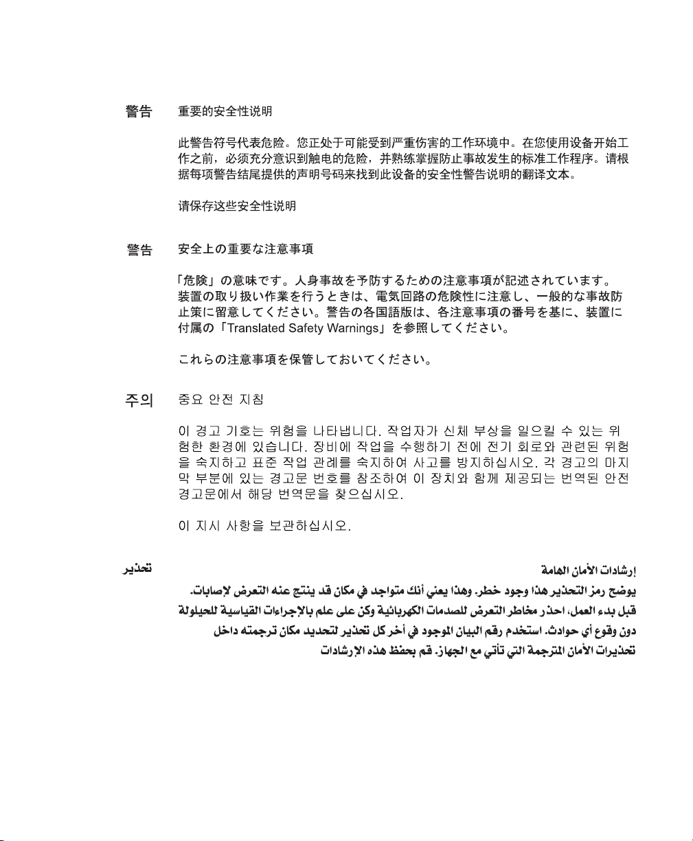
Warning Definition—Statement 1071
Warning
Waarschuwing
Varoitus
IMPORTANT SAFETY INSTRUCTIONS
This warning symbol means danger. You are in a situation that could cause
bodily injury. Before you work on any equipment, be aware of the hazards
involved with electrical circuitry and be familiar with standard practices for
preventing accidents. Use the statement number provided at the end of each
warning to locate its translation in the translated safety warnings that
accompanied this device.
SAVE THESE INSTRUCTIONS
BELANGRIJKE VEILIGHEIDSINSTRUCTIES
Dit waarschuwingssymbool betekent gevaar. U verkeert in een situatie die
lichamelijk letsel kan veroorzaken. Voordat u aan enige apparatuur gaat
werken, dient u zich bewust te zijn van de bij elektrische schakelingen
betrokken risico's en dient u op de hoogte te zijn van de standaard praktijken
om ongelukken te voorkomen. Gebruik het nummer van de verklaring
onderaan de waarschuwing als u een vertaling van de waarschuwing die bij
het apparaat wordt geleverd, wilt raadplegen.
BEWAAR DEZE INSTRUCTIES
TÄRKEITÄ TURVALLISUUSOHJEITA
Tämä varoitusmerkki merkitsee vaaraa. Tilanne voi aiheuttaa ruumiillisia
vammoja. Ennen kuin käsittelet laitteistoa, huomioi sähköpiirien
käsittelemiseen liittyvät riskit ja tutustu onnettomuuksien yleisiin
ehkäisytapoihin. Turvallisuusvaroitusten käännökset löytyvät laitteen
mukana toimitettujen käännettyjen turvallisuusvaroitusten joukosta
varoitusten lopussa näkyvien lausuntonumeroiden avulla.
Statement 1071
14
SÄILYTÄ NÄMÄ OHJEET
Page 15

Attention
Warnung
Avvertenza
IMPORTANTES INFORMATIONS DE SÉCURITÉ
Ce symbole d'avertissement indique un danger. Vous vous trouvez dans une
situation pouvant entraîner des blessures ou des dommages corporels. Avant
de travailler sur un équipement, soyez conscient des dangers liés aux circuits
électriques et familiarisez-vous avec les procédures couramment utilisées
pour éviter les accidents. Pour prendre connaissance des traductions des
avertissements figurant dans les consignes de sécurité traduites qui
accompagnent cet appareil, référez-vous au numéro de l'instruction situé à la
fin de chaque avertissement.
CONSERVEZ CES INFORMATIONS
WICHTIGE SICHERHEITSHINWEISE
Dieses Warnsymbol bedeutet Gefahr. Sie befinden sich in einer Situation, die
zu Verletzungen führen kann. Machen Sie sich vor der Arbeit mit Geräten mit
den Gefahren elektrischer Schaltungen und den üblichen Verfahren zur
Vorbeugung vor Unfällen vertraut. Suchen Sie mit der am Ende jeder Warnung
angegebenen Anweisungsnummer nach der jeweiligen Übersetzung in den
übersetzten Sicherheitshinweisen, die zusammen mit diesem Gerät
ausgeliefert wurden.
BEWAHREN SIE DIESE HINWEISE GUT AUF.
IMPORTANTI ISTRUZIONI SULLA SICUREZZA
Questo simbolo di avvertenza indica un pericolo. La situazione potrebbe
causare infortuni alle persone. Prima di intervenire su qualsiasi
apparecchiatura, occorre essere al corrente dei pericoli relativi ai circuiti
elettrici e conoscere le procedure standard per la prevenzione di incidenti.
Utilizzare il numero di istruzione presente alla fine di ciascuna avvertenza per
individuare le traduzioni delle avvertenze riportate in questo documento.
CONSERVARE QUESTE ISTRUZIONI
15
Page 16

Advarsel
Aviso
¡Advertencia!
VIKTIGE SIKKERHETSINSTRUKSJONER
Dette advarselssymbolet betyr fare. Du er i en situasjon som kan føre til skade
på person. Før du begynner å arbeide med noe av utstyret, må du være
oppmerksom på farene forbundet med elektriske kretser, og kjenne til
standardprosedyrer for å forhindre ulykker. Bruk nummeret i slutten av hver
advarsel for å finne oversettelsen i de oversatte sikkerhetsadvarslene som
fulgte med denne enheten.
TA VARE PÅ DISSE INSTRUKSJONENE
INSTRUÇÕES IMPORTANTES DE SEGURANÇA
Este símbolo de aviso significa perigo. Você está em uma situação que poderá
ser causadora de lesões corporais. Antes de iniciar a utilização de qualquer
equipamento, tenha conhecimento dos perigos envolvidos no manuseio de
circuitos elétricos e familiarize-se com as práticas habituais de prevenção de
acidentes. Utilize o número da instrução fornecido ao final de cada aviso para
localizar sua tradução nos avisos de segurança traduzidos que acompanham
este dispositivo.
GUARDE ESTAS INSTRUÇÕES
INSTRUCCIONES IMPORTANTES DE SEGURIDAD
Este símbolo de aviso indica peligro. Existe riesgo para su integridad física.
Antes de manipular cualquier equipo, considere los riesgos de la corriente
eléctrica y familiarícese con los procedimientos estándar de prevención de
accidentes. Al final de cada advertencia encontrará el número que le ayudará
a encontrar el texto traducido en el apartado de traducciones que acompaña
a este dispositivo.
16
GUARDE ESTAS INSTRUCCIONES
Page 17

Varning!
VIKTIGA SÄKERHETSANVISNINGAR
Denna varningssignal signalerar fara. Du befinner dig i en situation som kan
leda till personskada. Innan du utför arbete på någon utrustning måste du vara
medveten om farorna med elkretsar och känna till vanliga förfaranden för att
förebygga olyckor. Använd det nummer som finns i slutet av varje varning för
att hitta dess översättning i de översatta säkerhetsvarningar som medföljer
denna anordning.
SPARA DESSA ANVISNINGAR
17
Page 18
19 20 21
18
Page 19

Page 20

Page 21

Translated Warnings
This section contains the following warnings translated into multiple languages:
• Statement 1004—Installation Instructions, page 22
• Statement 1001—Work During Lightning Activity, page 23
• Statement 1021—SELV Circuit, page 24
• Statement 1045—Short-circuit Protection, page 27
• Statement 1074—Comply with Local and National Electrical Codes, page 29
• Statement 1040—Product Disposal, page 30
• Statement 19—TN Power Warning, page 34
• Statement 331—Power Supply Installation Warning, page 35
Page 22

• Statement 353—This Product Must be Connected, page 36
• Statement 1005—Circuit Breaker, page 37
• Statement 1019—Main Disconnecting Device, page 39
Statement 1004—Installation Instructions
Warning
Waarschuwing
Varoitus
Attention
Warnung
Avvertenza
Advarsel
Aviso
¡Advertencia!
Read the installation instructions before connecting the system to the power
source.
Statement 1004
Raadpleeg de installatie-instructies voordat u het systeem op de voedingsbron
aansluit.
Lue asennusohjeet ennen järjestelmän yhdistämistä virtalähteeseen.
Avant de brancher le système sur la source d'alimentation, consulter les
directives d'installation.
Vor dem Anschließen des Systems an die Stromquelle die
Installationsanweisungen lesen.
Consultare le istruzioni di installazione prima di collegare il sistema
all'alimentatore.
Les installasjonsinstruksjonene før systemet kobles til strømkilden.
Leia as instruções de instalação antes de ligar o sistema à fonte de energia.
Lea las instrucciones de instalación antes de conectar el sistema a la red de
alimentación.
22
Varning!
Läs installationsanvisningarna innan du kopplar systemet till
strömförsörjningsenheten.
Page 23

Statement 1001—Work During Lightning Activity
Warning
Waarschuwing
Varoitus
Attention
Warnung
Avvertenza
Advarsel
Aviso
Do not work on the system or connect or disconnect cables during periods of
lightning activity.
Statement 1001
Tijdens onweer dat gepaard gaat met bliksem, dient u niet aan het systeem te
werken of kabels aan te sluiten of te ontkoppelen.
Älä työskentele järjestelmän parissa äläkä yhdistä tai irrota kaapeleita
ukkosilmalla.
Ne pas travailler sur le système ni brancher ou débrancher les câbles pendant
un orage.
Arbeiten Sie nicht am System und schließen Sie keine Kabel an bzw. trennen
Sie keine ab, wenn es gewittert.
Non lavorare sul sistema o collegare oppure scollegare i cavi durante un
temporale con fulmini.
Utfør aldri arbeid på systemet, eller koble kabler til eller fra systemet når det
tordner eller lyner.
Não trabalhe no sistema ou ligue e desligue cabos durante períodos de mau
tempo (trovoada).
23
Page 24

¡Advertencia!
Varning!
No operar el sistema ni conectar o desconectar cables durante el transcurso
de descargas eléctricas en la atmósfera.
Vid åska skall du aldrig utföra arbete på systemet eller ansluta eller koppla
loss kablar.
Statement 1021—SELV Circuit
Waarschuwing
24
Warning
To avoid electric shock, do not connect safety extra-low voltage (SELV)
circuits to telephone-network voltage (TNV) circuits. LAN ports contain SELV
circuits, and WAN ports contain TNV circuits. Some LAN and WAN ports both
use RJ-45 connectors. Use caution when connecting cables.
Om elektrische schokken te vermijden, mogen veiligheidscircuits met extra
lage spanning (genaamd SELV = Safety Extra-Low Voltage) niet met
telefoonnetwerkspanning (TNV) circuits verbonden worden. LAN (Lokaal
netwerk) poorten bevatten SELV circuits en WAN (Regionaal netwerk) poorten
bevatten TNV circuits. Sommige LAN en WAN poorten gebruiken allebei RJ-45
connectors. Ga voorzichtig te werk wanneer u kabels verbindt.
Statement 1021
Page 25

Varoitus
Attention
Warnung
Avvertenza
Jotta vältyt sähköiskulta, älä kytke pienjännitteisiä SELV-suojapiirejä
puhelinverkkojännitettä (TNV) käyttäviin virtapiireihin. LAN-portit sisältävät
SELV-piirejä ja WAN-portit puhelinverkkojännitettä käyttäviä piirejä. Osa
sekä LAN- että WAN-porteista käyttää RJ-45-liittimiä. Ole varovainen
kytkiessäsi kaapeleita.
Pour éviter une électrocution, ne raccordez pas les circuits de sécurité basse
tension (Safety Extra-Low Voltage ou SELV) à des circuits de tension de réseau
téléphonique (Telephone Network Voltage ou TNV). Les ports du réseau local
(LAN) contiennent des circuits SELV et les ports du réseau longue distance
(WAN) sont munis de circuits TNV. Certains ports LAN et WAN utilisent des
connecteurs RJ-45. Raccordez les câbles en prenant toutes les précautions
nécessaires.
Zur Vermeidung von Elektroschock die
Sicherheits-Kleinspannungs-Stromkreise (SELV-Kreise) nicht an
Fernsprechnetzspannungs-Stromkreise (TNV-Kreise) anschließen. LAN-Ports
enthalten SELV-Kreise, und WAN-Ports enthalten TNV-Kreise. Einige LAN- und
WAN-Ports verwenden auch RJ-45-Steckverbinder. Vorsicht beim
Anschließen von Kabeln.
Per evitare scosse elettriche, non collegare circuiti di sicurezza a tensione
molto bassa (SELV) ai circuiti a tensione di rete telefonica (TNV). Le porte LAN
contengono circuiti SELV e le porte WAN contengono circuiti TNV. Alcune
porte LAN e WAN fanno uso di connettori RJ-45. Fare attenzione quando si
collegano cavi.
Advarsel
Aviso
Unngå å koble lavspenningskretser (SELV) til kretser for telenettspenning
(TNV), slik at du unngår elektrisk støt. LAN-utganger inneholder SELV-kretser
og WAN-utganger inneholder TNV-kretser. Det finnes både LAN-utganger og
WAN-utganger som bruker RJ-45-kontakter. Vær forsiktig når du kobler
kabler.
Para evitar choques eléctricos, não conecte os circuitos de segurança de
baixa tensão (SELV) aos circuitos de tensão de rede telefónica (TNV). As
portas LAN contêm circuitos SELV e as portas WAN contêm circuitos TNV.
Algumas portas LAN e WAN usam conectores RJ-45. Tenha o devido cuidado
ao conectar os cabos.
25
Page 26
¡Advertencia!
Varning!
Para evitar la sacudida eléctrica, no conectar circuitos de seguridad de
voltaje muy bajo (safety extra-low voltage = SELV) con circuitos de voltaje de
red telefónica (telephone network voltage = TNV). Los puertos de redes de
área local (local area network = LAN) contienen circuitos SELV, y los puertos
de redes de área extendida (wide area network = WAN) contienen circuitos
TNV. En algunos casos, tanto los puertos LAN como los WAN usan conectores
RJ-45. Proceda con precaución al conectar los cables.
För att undvika elektriska stötar, koppla inte säkerhetskretsar med extra låg
spänning (SELV-kretsar) till kretsar med telefonnätspänning (TNV-kretsar).
LAN-portar innehåller SELV-kretsar och WAN-portar innehåller TNV-kretsar.
Vissa LAN- och WAN-portar är försedda med RJ-45-kontakter. Iaktta
försiktighet vid anslutning av kablar.
26
Page 27

Statement 1045—Short-circuit Protection
27
Page 28

29
28
Page 29
Statement 1074—Comply with Local and National Electrical Codes
Warning
Waarschuwing
Varoitus
Attention
Warnung
Avvertenza
Advarsel
Aviso
¡Advertencia!
Installation of the equipment must comply with local and national electrical
codes.
Statement 1074
Bij installatie van de apparatuur moet worden voldaan aan de lokale en
nationale elektriciteitsvoorschriften.
Laitteisto tulee asentaa paikallisten ja kansallisten sähkömääräysten
mukaisesti.
L'équipement doit être installé conformément aux normes électriques
nationales et locales.
Die Installation der Geräte muss den Sicherheitsstandards entsprechen.
L'installazione dell'impianto deve essere conforme ai codici elettrici locali e
nazionali.
Installasjon av utstyret må samsvare med lokale og nasjonale
elektrisitetsforskrifter.
A instalação do equipamento tem de estar em conformidade com os códigos
eléctricos locais e nacionais.
La instalación del equipo debe cumplir con las normativas de electricidad
locales y nacionales.
Varning!
Installation av utrustningen måste ske i enlighet med gällande
elinstallationsföreskrifter.
Page 30
Statement 1040—Product Disposal
Warning
Waarschuwing
Varoitus
Attention
Warnung
Avvertenza
Advarsel
Aviso
Ultimate disposal of this product should be handled according to all national
laws and regulations.
Statement 1040
Het uiteindelijke wegruimen van dit product dient te geschieden in
overeenstemming met alle nationale wetten en reglementen.
Tämä tuote on hävitettävä kansallisten lakien ja määräysten mukaisesti.
La mise au rebut ou le recyclage de ce produit sont généralement soumis à des
lois et/ou directives de respect de l'environnement. Renseignez-vous auprès
de l'organisme compétent.
Die Entsorgung dieses Produkts sollte gemäß allen Bestimmungen und
Gesetzen des Landes erfolgen.
Lo smaltimento di questo prodotto deve essere eseguito secondo le leggi e
regolazioni locali.
Endelig kassering av dette produktet skal være i henhold til alle relevante
nasjonale lover og bestemmelser.
Deitar fora este produto em conformidade com todas as leis e regulamentos
nacionais.
30
¡Advertencia!
Al deshacerse por completo de este producto debe seguir todas las leyes y
reglamentos nacionales.
Page 31
Varning!
Aviso
Advarsel
Vid deponering hanteras produkten enligt gällande lagar och bestämmelser.
O descarte definitivo deste produto deve estar de acordo com todas as leis e
regulamentações nacionais.
Endelig bortskaffelse af dette produkt skal ske i henhold til gældende love og
regler.
31
Page 32

Statement 353—This Product Must be Connected
Waarschuwing
32
Warning
Varoitus
Attention
This product must be connected to a power-over-ethernet (PoE) IEEE 802.3af
compliant power source or an IEC60950 compliant limited power source.
Statement 353
Dit product moet worden verbonden met een stroomvoorziening die
compatibel is met PoE (power-over-ethernet) IEEE 802.3af of een beperkte
stroomvoorziening die compatibel is met IEC60950.
Tämä tuote on liitettävä PoE (power-over-ethernet) IEEE 802.3af
-yhteensopivaan virtalähteeseen tai IEC60950-yhteensopivaan rajoitettuun
virtalähteeseen.
Ce produit doit être connecté à une source d'alimentation électrique par câble
Ethernet (PoE) conforme à la norme IEEE 802.3af ou à une source
d'alimentation limitée conforme à la norme IEC60950.
Page 33

Warnung
Avvertenza
Advarsel
Aviso
¡Advertencia!
Varning!
Dieses Produkt muss entweder an eine Stromquelle angeschlossen sein, die
mit dem IEEE 802.3af-Standard Power-over-Ethernet (PoE) kompatibel ist oder
an eine Stromquelle für geringe Leistungen, die IEC60950-kompatibel ist.
Questo prodotto deve essere connesso a una fonte di alimentazione di tipo PoE
(power-over-ethernet) conforme a IEEE 802.3af o a una fonte di alimentazione
conforme a IEC60950.
Dette produktet må være koblet til en Power-over-Ethernet (PoE) IEEE
802.3af-kompatibel strømkilde eller en IEC60950-kompatibel begrenset
strømkilde.
Este produto tem de estar ligado a uma fonte de alimentação compatível com
a norma IEEE 802.3af, também conhecida pela sigla Power over Ethernet (PoE),
ou a uma fonte de alimentação limitada compatível com a norma IEC60950.
Debe conectar este producto a una fuente de alimentación sobre ethernet
(PoE) conforme con el estándar IEEE 802.3af, o a una fuente limitada conforme
con el estándar IEC60950.
Denna produkt måste vara ansluten till en PoE IEEE 802.3af-kompatibel
strömkälla eller en IEC60950-kompatibel begränsad strömkälla.
33
Page 34

When using an AC/DC power supply, the following warnings apply:
• Statement 19—TN Power Warning, page 34
• Statement 331—Power Supply Installation Warning, page 35
• Statement 353—This Product Must be Connected, page 36
• Statement 1005—Circuit Breaker, page 37
• Statement 1019—Main Disconnecting Device, page 39
Statement 19—TN Power Warning
Waarschuwing
34
Warning
Varoitus
Attention
Warnung
Avvertenza
Advarsel
Aviso
The device is designed to work with TN power systems.
Statement 19
Het apparaat is ontworpen om te functioneren met TN energiesystemen.
Koje on suunniteltu toimimaan TN-sähkövoimajärjestelmien yhteydessä.
Ce dispositif a été conçu pour fonctionner avec des systèmes d'alimentation
TN.
Das Gerät ist für die Verwendung mit TN-Stromsystemen ausgelegt.
Il dispositivo è stato progettato per l’uso con sistemi di alimentazione TN.
Utstyret er utfomet til bruk med TN-strømsystemer.
O dispositivo foi criado para operar com sistemas de corrente TN.
Page 35

¡Advertencia!
Varning!
El equipo está diseñado para trabajar con sistemas de alimentación tipo TN.
Enheten är konstruerad för användning tillsammans med elkraftssystem av
TN-typ.
Statement 331—Power Supply Installation Warning
Warning
The power supply must be placed indoors.
Statement 331
Waarschuwing
Varoitus
Attention
Warnung
Avvertenza
Advarsel
Aviso
De stroomtoevoer moet binnen worden geplaatst.
Tehonlähde on sijoitettava sisätiloihin.
Le bloc d’alimentation électrique doit être placé à l’intérieur.
Die Stromversorgungsquelle darf nicht im Freien aufgestellt werden.
L’alimentatore deve essere posto in un luogo interno.
Strømkilden skal være plassert innendørs.
A fonte de alimentação deve ser instalada no interior.
35
Page 36

¡Advertencia!
Varning!
El suministro de energía debe estar ubicado en un lugar cubierto y no al aire
libre.
Strömkällan måste vara placerad inomhus.
Statement 353—This Product Must be Connected
36
Page 37

Statement 1005—Circuit Breaker
Warning
Waarschuwing
Varoitus
Attention
Warnung
Avvertenza
This product relies on the building’s installation for short-circuit (overcurrent)
protection. Ensure that the protective device is rated not greater than:
120 VAC, 15A (U.S./CAN); 240 VAC, 10A (INTERNATIONAL)
Statement 1005
Dit product is afhankelijk van de installatie van het gebouw voor beveiliging
tegen kortsluiting (overstroom). Controleer of de beschermingsinrichting niet
meer dan:
120 VAC, 15A (U.S./CAN); 240 VAC, 10A (INTERNATIONAL) is.
Tämä tuote on riippuvainen rakennukseen asennetusta
oikosulkusuojauksesta (ylivirtasuojauksesta). Varmista, että suojalaitteen
mitoitus ei ole yli:
120 VAC, 15A (U.S./CAN); 240 VAC, 10A (INTERNATIONAL)
Pour ce qui est de la protection contre les courts-circuits (surtension), ce
produit dépend de l'installation électrique du local. Vérifiez que le courant
nominal du dispositif de protection n'est pas supérieur à :
120 VAC, 15A (U.S./CAN); 240 VAC, 10A (INTERNATIONAL)
Dieses Produkt ist darauf angewiesen, dass im Gebäude ein Kurzschlussbzw. Überstromschutz installiert ist. Stellen Sie sicher, dass der Nennwert der
Schutzvorrichtung nicht mehr als:
120 VAC, 15A (U.S./CAN); 240 VAC, 10A (INTERNATIONAL) beträgt.
Questo prodotto dipende dall'impianto dell'edificio per quanto riguarda la
protezione contro cortocircuiti (sovracorrente). Assicurarsi che il dispositivo
di protezione non abbia un rating superiore a:
120 VAC, 15A (U.S./CAN); 240 VAC, 10A (INTERNATIONAL)
Advarsel
Dette produktet er avhengig av bygningens installasjoner av kortslutnings
(overstrøm)-beskyttelse. Påse at verneenheten ikke er merket høyere enn:
120 VAC, 15A (U.S./CAN); 240 VAC, 10A (INTERNATIONAL)
37
Page 38

Aviso
¡Advertencia!
Varning!
Este produto depende das instalações existentes para proteção contra
curto-circuito (sobrecarga). Assegure-se de que o fusível ou disjuntor não
seja superior a:
120 VAC, 15A (U.S./CAN); 240 VAC, 10A (INTERNATIONAL)
Este equipo utiliza el sistema de protección contra cortocircuitos (o sobrecorrientes)
del edificio. Asegúrese de que el dispositivo de protección no sea superior a:
120 VAC, 15A (U.S./CAN); 240 VAC, 10A (INTERNATIONAL)
Denna produkt är beroende av i byggnaden installerat kortslutningsskydd
(överströmsskydd). Kontrollera att skyddsanordningen inte har högre
märkvärde än:
120 VAC, 15A (U.S./CAN); 240 VAC, 10A (INTERNATIONAL)
120 VAC, 15A (U.S./CAN); 240 VAC, 10A (INTERNATIONAL)
120 VAC, 15A (U.S./CAN); 240 VAC, 10A (INTERNATIONAL)
38
120 VAC, 15A (U.S./CAN); 240 VAC, 10A (INTERNATIONAL)
120 VAC, 15A (U.S./CAN); 240 VAC, 10A (INTERNATIONAL)
Page 39
Statement 1019—Main Disconnecting Device
Warning
Waarschuwing
Varoitus
Attention
Warnung
Avvertenza
Advarsel
Aviso
The plug-socket combination must be accessible at all times, because it
serves as the main disconnecting device.
Statement 1019
De combinatie van de stekker en het elektrisch contactpunt moet te allen tijde
toegankelijk zijn omdat deze het hoofdmechanisme vormt voor verbreking van
de aansluiting.
Pistoke/liitinkohta toimii pääkatkaisumekanismina. Pääsy siihen on pidettävä
aina esteettömänä.
La combinaison de prise de courant doit être accessible à tout moment parce
qu'elle fait office de système principal de déconnexion.
Der Netzkabelanschluß am Gerät muß jederzeit zugänglich sein, weil er als
primäre Ausschaltvorrichtung dient.
Il gruppo spina-presa deve essere sempre accessibile, poiché viene utilizzato
come dispositivo di scollegamento principale.
Kombinasjonen støpsel/uttak må alltid være tilgjengelig ettersom den
fungerer som hovedfrakoplingsenhet.
A combinação ficha-tomada deverá ser sempre acessível, porque funciona
como interruptor principal.
¡Advertencia!
Varning!
El conjunto de clavija y toma ha de encontrarse siempre accesible ya que
hace las veces de dispositivo de desconexión principal.
Man måste alltid kunna komma åt stickproppen i uttaget, eftersom denna
koppling utgör den huvudsakliga frånkopplingsanordningen.
39
Page 40

European Directives
Statement 275—Declaration of Conformity with Regard to the Directives
73/23/EEC and 89/336/EEC as amended by Directive 93/68/EEC
For specifics about which standards have been applied, refer to the Declaration of Conformity.
40
English:
Dansk:
Deutsch:
Español:
This equipment is in compliance with the essential requirements and other
provisions of Directives 73/23/EEC and 89/336/EEC as amended by Directive
93/68/EEC.
Dette udstyr er i overensstemmelse med de ufravigelige hensyn og andre
bestemmelser i direktiv 73/23/EEC og 89/336/EEC som ændred i direktiv
93/68/EEC.
Dieses Gerät entspricht den wesentlichen Anforderungen und weiteren
Bestimmungen der Richtlinien 73/23/EWG und 89/336/EWG mit der Ergänzung
durch Richtlinie 93/68/EWG.
Este equipo cumple con los requisitos esenciales y otras disposiciones de las
Directrices 73/23/EEC y 89/336/EEC de acuerdo a las modificaciones de la
Directriz 93/68/EEC.
Page 41

Français:
Íslenska:
Italiano:
Nederlands:
Norsk:
Português:
Cet appareil remplit les principales conditions requises et autres dispositions
des Directives 73/23/EEC et 89/336/EEC, modifiées par la Directive 93/68/EEC.
Þessir búnaður samrýmist lögboðnum kröfum og öðrum ákvæðum tilskipana
73/23/EBE og 89/336/EBE, með breytingum skv. tilskipun 93/68/EBE.
Questa apparecchiatura è conforme ai requisiti essenziali e altre disposizioni
delle Direttive 73/23/EEC e 89/336/EEC modificate con la Direttiva 93/68/EEC.
Deze apparatuur voldoet aan de belangrijkste eisen en andere voorzieningen
van richtlijnen 73/23/EEC en 89/336/EEC zoals gewijzigd door richtlijn
93/68/EEC.
Dette utstyret samsvarer med de vesentligste kravene og andre regler i
direktivene 73/23/EEC og 89/336/EEC samt i tilleggsdirektiv 93/68/EEC.
Este equipamento satisfaz os requisitos essenciais e outras provisões das
Directivas 73/23/EEC e 89/336/EEC, conforme amendados pela Directiva
93/68/EEC.
Suomalainen:
Svenska:
Cisco UnifiedCommunications Sensor CUSM-1040A-2PK
Tämä laite on direktiivien 73/23/ETY ja 89/336/ETY (kuten muutettu
direktiivissä 93/68/ETY) keskeisten vaatimusten ja määräysten mukainen.
Denna utrustning uppfyller de väsentliga kraven och andra villkor i direktiven
73/23/EEC och 89/336/EEC enligt ändringarna i direktiv 93/68/EEC.
41
Page 42

Regulatory Standards Compliance
This section includes all regulatory, safety, and electromagnetic compatibility (EMC) standards. The
Cisco 1040 is in compliance with national and international standards as described in Table 3.
Table 3 Regulatory Standards Compliance
Specification Description
Regulatory Compliance Products with the CE Marking indicate compliance with the
89/336/EEC and 73/23/EEC directives, which include the
safety and EMC standards listed.
Safety UL 60950
CAN/CSA-C22.2 No. 60950
EN 60950
IEC 60950
AS/NZS 60950
EMC 47CFR Part 15 (FCC) Class B
AS/NZS CISPR22 Class B
CISPR22 Class B
CNS13438 Class B
EN55022 Class B
ICES003 Class B
VCCI Class B
EN50082-1
EN61000-6-1
EN55024
EN61000-3-2
EN61000-3-3
For specific details about the years, revisions and relevant amendments please refer to the applicable
declaration of conformity available at http://www.cisco.com.
42
Page 43

EMC Environmental Conditions for Products Installed in the European Union
This section applies to products to be installed in the European Union.
The equipment is intended to operate under the following environmental conditions with respect to
EMC:
• A separate defined location under user’s control.
• Earthing and bonding shall meet the requirements of ETS 300 253 or CCITT K27.
• AC power distribution shall be one of the following types, where applicable: TN-S and TN-C as
defined in IEC 364-3.
In addition, if equipment is operated in a domestic environment, interference may occur.
EMC Class B Notices and Warnings
This section includes the EMC Class B warnings for the Cisco 1040.
Class B Notice for FCC
Modifying the equipment without Cisco’s authorization may result in the equipment no longer
complying with FCC requirements for Class B digital devices. In that event, your right to use the
equipment may be limited by FCC regulations, and you may be required to correct any interference to
radio or television communications at your own expense.
This equipment has been tested and found to comply with the limits for a Class B digital device,
pursuant to Part 15 of the FCC Rules. These limits are designed to provide reasonable protection
against harmful interference in a residential installation. This equipment generates, uses and can
radiate radio frequency energy and, if not installed and used in accordance with the instructions, may
cause harmful interference to radio communications. However, there is no guarantee that interference
will not occur in a particular installation. If this equipment does cause harmful interference to radio
or television reception, which can be determined by turning the equipment off and on, the user is
encouraged to try to correct the interference by one or more of the following measures:
• Reorient or relocate the receiving antenna.
• Increase the separation between the equipment and receiver.
• Connect the equipment into an outlet on a circuit different from that to which the receiver is
connected.
• Consult the dealer or an experienced radio/TV technician for help.
43
Page 44
Class B Notice for Canada
This Class B digital apparatus complies with Canadian ICES-003.
Cet appareil numérique de la classe B est conforme à la norme NMB-003 du Canada.
Statement 295—Class B Warning for Korea
Warning
This is a Class B Device and is registered for EMC requirements for residential
use. This device can be used not only in residential areas but in all other areas.
Statement 157—VCCI Compliance for Class B Equipment
Warning
This is a Class B product based on the standard of the Voluntary Control Council
for Interference from Information Technology Equipment (VCCI). If this is used
near a radio or television receiver in a domestic environment, it may cause
radio interference. Install and use the equipment according to the instruction
manual.
44
Page 45

9 Obtaining Documentation
Cisco documentation and additional literature are available on Cisco.com. This section explains the
product documentation resources that Cisco offers.
Cisco.com
You can access the most current Cisco documentation at this URL:
http://www.cisco.com/techsupport
You can access the Cisco website at this URL:
http://www.cisco.com
You can access international Cisco websites at this URL:
http://www.cisco.com/public/countries_languages.shtml
Product Documentation DVD
The Product Documentation DVD is a library of technical product documentation on a portable
medium. The DVD enables you to access installation, configuration, and command guides for Cisco
hardware and software products. With the DVD, you have access to the HTML documentation and
some of the PDF files found on the Cisco website at this URL:
http://www.cisco.com/univercd/home/home.htm
The Product Documentation DVD is created and released regularly. DVDs are available singly or by
subscription. Registered Cisco.com users can order a Product Documentation DVD (product number
DOC-DOCDVD= or DOC-DOCDVD=SUB) from Cisco Marketplace at the Product Documentation
Store at this URL:
http://www.cisco.com/go/marketplace/docstore
Ordering Documentation
You must be a registered Cisco.com user to access Cisco Marketplace. Registered users may order
Cisco documentation at the Product Documentation Store at this URL:
http://www.cisco.com/go/marketplace/docstore
If you do not have a user ID or password, you can register at this URL:
http://tools.cisco.com/RPF/register/register.do
45
Page 46

10 Documentation Feedback
You can provide feedback about Cisco technical documentation on the Cisco Support site area by
entering your comments in the feedback form available in every online document.
11 Cisco Product Security Overview
Cisco provides a free online Security Vulnerability Policy portal at this URL:
http://www.cisco.com/en/US/products/products_security_vulnerability_policy.html
From this site, you will find information about how to do the following:
• Report security vulnerabilities in Cisco products
• Obtain assistance with security incidents that involve Cisco products
• Register to receive security information from Cisco
A current list of security advisories, security notices, and security responses for Cisco products is
available at this URL:
http://www.cisco.com/go/psirt
To see security advisories, security notices, and security responses as they are updated in real time, you
can subscribe to the Product Security Incident Response Team Really Simple Syndication (PSIRT RSS)
feed. Information about how to subscribe to the PSIRT RSS feed is found at this URL:
http://www.cisco.com/en/US/products/products_psirt_rss_feed.html
Reporting Security Problems in Cisco Products
Cisco is committed to delivering secure products. We test our products internally before we release
them, and we strive to correct all vulnerabilities quickly. If you think that you have identified a
vulnerability in a Cisco product, contact PSIRT:
• For emergencies only— security-alert@cisco.com
An emergency is either a condition in which a system is under active attack or a condition for
which a severe and urgent security vulnerability should be reported. All other conditions are
considered nonemergencies.
• For nonemergencies— psirt@cisco.com
In an emergency, you can also reach PSIRT by telephone:
• 1 877 228-7302
• 1 408 525-6532
46
Page 47

Tip We encourage you to use Pretty Good Privacy (PGP) or a compatible product (for example,
GnuPG) to encrypt any sensitive information that you send to Cisco. PSIRT can work with
information that has been encrypted with PGP versions 2.x through 9.x.
Never use a revoked encryption key or an expired encryption key. The correct public key to
use in your correspondence with PSIRT is the one linked in the Contact Summary section of
the Security Vulnerability Policy page at this URL:
http://www.cisco.com/en/US/products/products_security_vulnerability_policy.html
The link on this page has the current PGP key ID in use.
If you do not have or use PGP, contact PSIRT to find other means of encrypting the data before
sending any sensitive material.
12 Product Alerts and Field Notices
Modifications to or updates about Cisco products are announced in Cisco Product Alerts and
Cisco Field Notices. You can receive these announcements by using the Product Alert Tool on
Cisco.com. This tool enables you to create a profile and choose those products for which you want
to receive information.
To access the Product Alert Tool, you must be a registered Cisco.com user. Registered users can access
the tool at this URL:
http://tools.cisco.com/Support/PAT/do/ViewMyProfiles.do?local=en
To register as a Cisco.com user, go to this URL:
http://tools.cisco.com/RPF/register/register.do
13 Obtaining Technical Assistance
Cisco Technical Support provides 24-hour-a-day award-winning technical assistance. The
Cisco Support website on Cisco.com features extensive online support resources. In addition, if
you have a valid Cisco service contract, Cisco Technical Assistance Center (TAC) engineers provide
telephone support. If you do not have a valid Cisco service contract, contact your reseller.
47
Page 48

Cisco Support Website
The Cisco Support website provides online documents and tools for troubleshooting and resolving
technical issues with Cisco products and technologies. The website is available 24 hours a day at
this URL:
http://www.cisco.com/en/US/support/index.html
Access to all tools on the Cisco Support website requires a Cisco.com user ID and password. If you
have a valid service contract but do not have a user ID or password, you can register at this URL:
http://tools.cisco.com/RPF/register/register.do
Note Before you submit a request for service online or by phone, use the Cisco Product
Identification Tool to locate your product serial number. You can access this tool from the
Cisco Support website by clicking the Get Tools & Resources link, clicking the All Tools
(A-Z) tab, and then choosing Cisco Product Identification Tool from the alphabetical list.
This tool offers three search options: by product ID or model name; by tree view; or, for
certain products, by copying and pasting show command output. Search results show an
illustration of your product with the serial number label location highlighted. Locate the serial
number label on your product and record the information before placing a service call.
Tip Displaying and Searching on Cisco.com
If you suspect that the browser is not refreshing a web page, force the browser to update the
web page by holding down the Ctrl key while pressing F5.
To find technical information, narrow your search to look in technical documentation, not the
entire Cisco.com website. After using the Search box on the Cisco.com home page, click the
Advanced Search link next to the Search box on the resulting page and then click the
Technical Support & Documentation radio button.
To provide feedback about the Cisco.com website or a particular technical document, click
Contacts & Feedback at the top of any Cisco.com web page.
48
Page 49

Submitting a Service Request
Using the online TAC Service Request Tool is the fastest way to open S3 and S4 service requests.
(S3 and S4 service requests are those in which your network is minimally impaired or for which you
require product information.) After you describe your situation, the TAC Service Request Tool
provides recommended solutions. If your issue is not resolved using the recommended resources, your
service request is assigned to a Cisco engineer. The TAC Service Request Tool is located at this URL:
http://www.cisco.com/techsupport/servicerequest
For S1 or S2 service requests, or if you do not have Internet access, contact the Cisco TAC by
telephone. (S1 or S2 service requests are those in which your production network is down or severely
degraded.) Cisco engineers are assigned immediately to S1 and S2 service requests to help keep your
business operations running smoothly.
To open a service request by telephone, use one of the following numbers:
Asia-Pacific: +61 2 8446 7411
Australia: 1 800 805 227
EMEA: +32 2 704 55 55
USA: 1 800 553 2447
For a complete list of Cisco TAC contacts, go to this URL:
http://www.cisco.com/techsupport/contacts
Definitions of Service Request Severity
To ensure that all service requests are reported in a standard format, Cisco has established severity
definitions.
Severity 1 (S1)—An existing network is “down” or there is a critical impact to your business
operations. You and Cisco will commit all necessary resources around the clock to resolve the
situation.
Severity 2 (S2)—Operation of an existing network is severely degraded, or significant aspects of your
business operations are negatively affected by inadequate performance of Cisco products. You and
Cisco will commit full-time resources during normal business hours to resolve the situation.
Severity 3 (S3)—Operational performance of the network is impaired while most business operations
remain functional. You and Cisco will commit resources during normal business hours to restore
service to satisfactory levels.
Severity 4 (S4)—You require information or assistance with Cisco product capabilities, installation, or
configuration. There is little or no effect on your business operations.
49
Page 50

14 Obtaining Additional Publications and Information
Information about Cisco products, technologies, and network solutions is available from various
online and printed sources.
• The Cisco Online Subscription Center is the website where you can sign up for a variety of Cisco
e-mail newsletters and other communications. Create a profile and then select the subscriptions
that you would like to receive. To visit the Cisco Online Subscription Center, go to this URL:
http://www.cisco.com/offer/subscribe
• The Cisco Product Quick Reference Guide is a handy, compact reference tool that includes brief
product overviews, key features, sample part numbers, and abbreviated technical specifications
for many Cisco products that are sold through channel partners. It is updated twice a year and
includes the latest Cisco channel product offerings. To order and find out more about the
Cisco Product Quick Reference Guide, go to this URL:
http://www.cisco.com/go/guide
• Cisco Marketplace provides a variety of Cisco books, reference guides, documentation, and logo
merchandise. Visit Cisco Marketplace, the company store, at this URL:
http://www.cisco.com/go/marketplace/
• Cisco Press publishes a wide range of general networking, training, and certification titles. Both
new and experienced users will benefit from these publications. For current Cisco Press titles and
other information, go to Cisco Press at this URL:
http://www.ciscopress.com
• Internet Protocol Journal is a quarterly journal published by Cisco for engineering professionals
involved in designing, developing, and operating public and private internets and intranets. You
can access the Internet Protocol Journal at this URL:
http://www.cisco.com/ipj
• Networking products offered by Cisco, as well as customer support services, can be obtained at
this URL:
http://www.cisco.com/en/US/products/index.html
• Networking Professionals Connection is an interactive website where networking professionals
share questions, suggestions, and information about networking products and technologies with
Cisco experts and other networking professionals. Join a discussion at this URL:
http://www.cisco.com/discuss/networking
50
Page 51

• “What’s New in Cisco Documentation” is an online publication that provides information about
the latest documentation releases for Cisco products. Updated monthly, this online publication is
organized by product category to direct you quickly to the documentation for your products. You
can view the latest release of “What’s New in Cisco Documentation” at this URL:
http://www.cisco.com/univercd/cc/td/doc/abtunicd/136957.htm
• World-class networking training is available from Cisco. You can view current offerings at
this URL:
http://www.cisco.com/en/US/learning/index.html
51
Page 52

Corporate Headquarters
Cisco Systems, Inc.
170 West Tasman Drive
San Jose, CA 95134-1706
USA
www.cisco.com
Tel: 408 526-4000
800 553-NETS (6387)
Fax: 408 526-4100
European Headquarters
Cisco Systems International BV
Haarlerbergpark
Haarlerbergweg 13-19
1101 CH Amsterdam
The Netherlands
www-europe.cisco.com
Tel: 31 0 20 357 1000
Fax: 31 0 20 357 1100
Americas Headquarters
Cisco Systems, Inc.
170 West Tasman Drive
San Jose, CA 95134-1706
USA
www.cisco.com
Tel: 408 526-7660
Fax: 408 527-0883
Asia Pacific Headquarters
Cisco Systems, Inc.
168 Robinson Road
#28-01 Capital Tower
Singapore 068912
www.cisco.com
Tel: +65 6317 7777
Fax: +65 6317 7799
Cisco Systems has more than 200 offices in the following countries. Addresses, phone numbers, and fax numbers are listed on the
Cisco Website at www.cisco.com/go/offices
Argentina • Australia • Austria • Belgium • Brazil • Bulgaria • Canada • Chile • China PRC • Colombia • Costa Rica • Croatia • Cyprus • Czech Republic • Denmark • Dubai, UAE
Finland • France • Germany • Greece • Hong Kong SAR • Hungary • India • Indonesia • Ireland • Israel • Italy • Japan • K orea • Luxembourg • Malaysia • Mexico
The Netherlands • New Zealand • Norway • Peru • Philippines • Poland • Portugal • Puerto Rico • Romania • Russia • Saudi Arabia • Scotland • Singapore
Slovakia • Slovenia • South Africa • Spain • Sweden • Switzerland • Taiwan • Thailand • Turkey • Ukraine • United Kingdom • United States • Venezuela • Vietnam • Zimbabwe
© 2005-2006 Cisco Systems, Inc. All rights reserved.
Printed in the USA on recycled paper containing 10% postconsumer waste.
78-17676-01
 Loading...