

Page 1

Welcome to the Product Guide!Product Guide
The Product Guide describes the Cisco SWAN products.
Refer to the OVERVIEWS section to see a big picture view of Cisco SWAN products and
features.
Cisco SWAN 2.2: Last Updated April 1, 2005
See the SOLUTIONS
specific solutions to real-world problems.
Go to the TASKS
and troubleshoot Cisco SWAN products and supported 802.11 networks.
Visit the REFERENCES
Supported Country Codes, CLI Reference, Web User Interface Online Help files, Cisco
WCS Online Help files, Cisco 1000 Series Lightweight Access Point Deployment Guide,
Hardware and Software Quick Start Guides, and pointers to the current Release Notes.
FCC Statements for Cisco 4100 Series Wireless LAN Controllers
FCC Statements for Cisco 2000 Series Wireless LAN Controllers
FCC Statements for Cisco 1000 Series Lightweight Access Points
Industry Canada Required User Information for Cisco 1000 Series Lightweight Access Points
Legal Information
Obtaining Documentation
Documentation Feedback
Cisco Product Security Overview
Obtaining Technical Assistance
section to look through real-world network and application-
section to find detailed instructions on how to install, configure, use,
section to find technical information, such as the Glossary,
4/1/05 © 2005 All Rights Reserved.
OL-7426-02
Page 2

Obtaining Additional Publications and Information
Cisco SWAN Release Notes
Cisco WCS Release Notes
4/1/05 Product Guide
OL-7426-02
Page 3

Legal InformationLegal Information
This section includes the following legal information:
• Products
• End User License Agreement
• Limited Warranty
• General Terms Applicable to the Limited Warranty Statement and End User License Agreement
• Additional Open Source Terms
• Trademarks and Service Marks
The following describes the Cisco Systems, Inc. standard Product Warranty for End Customers.
ProductsProducts
• Cisco 2000 Series Wireless LAN Controllers
• Cisco 4100 Series Wireless LAN Controllers
• Cisco 1000 Series IEEE 802.11a/b/g lightweight access points
End User License AgreementEnd User License Agreement
IMPORTANT: PLEASE READ THIS END USER LICENSE AGREEMENT CAREFULLY. DOWNLOADING, INSTALLING OR USING CISCO OR CISCO-SUPPLIED SOFTWARE CONSTITUTES
ACCEPTANCE OF THIS AGREEMENT.
CISCO IS WILLING TO LICENSE THE SOFTWARE TO YOU ONLY UPON THE CONDITION THAT YOU
ACCEPT ALL OF THE TERMS CONTAINED IN THIS LICENSE AGREEMENT. BY DOWNLOADING OR
INSTALLING THE SOFTWARE, OR USING THE EQUIPMENT THAT CONTAINS THIS SOFTWARE, YOU ARE
BINDING YOURSELF AND THE BUSINESS ENTITY THAT YOU REPRESENT (COLLECTIVELY,
“CUSTOMER”) TO THIS AGREEMENT. IF YOU DO NOT AGREE TO ALL OF THE TERMS OF THIS AGREEMENT, THEN CISCO IS UNWILLING TO LICENSE THE SOFTWARE TO YOU AND (A) DO NOT DOWNLOAD,
INSTALL OR USE THE SOFTWARE, AND (B) YOU MAY RETURN THE SOFTWARE FOR A FULL REFUND,
OR, IF THE SOFTWARE IS SUPPLIED AS PART OF ANOTHER PRODUCT, YOU MAY RETURN THE ENTIRE
PRODUCT FOR A FULL REFUND. YOUR RIGHT TO RETURN AND REFUND EXPIRES 30 DAYS AFTER
PURCHASE FROM CISCO OR AN AUTHORIZED CISCO RESELLER, AND APPLIES ONLY IF YOU ARE THE
ORIGINAL END USER PURCHASER.
The following terms of this End User License Agreement (“Agreement”) govern Customer’s access and
use of the Software, except to the extent (a) there is a separate signed agreement between Customer
and Cisco governing Customer’s use of the Software or (b) the Software includes a separate
“click-accept” license agreement as part of the installation and/or download process. To the extent of a
conflict between the provisions of the foregoing documents, the order of precedence shall be (1) the
signed agreement, (2) the click-accept agreement, and (3) this End User License Agreement.
License. Conditioned upon compliance with the terms and conditions of this Agreement, Cisco
Systems, Inc. or its subsidiary licensing the Software instead of Cisco Systems, Inc. (“Cisco”), grants to
Customer a nonexclusive and nontransferable license to use for Customer’s internal business purposes
the Software and the Documentation for which Customer has paid the required license fees. “Documentation” means written information (whether contained in user or technical manuals, training materials,
specifications or otherwise) specifically pertaining to the Software and made available by Cisco with the
Software in any manner (including on CD-ROM, or on-line).
Customer’s license to use the Software shall be limited to, and Customer shall not use the Software in
excess of, a single hardware chassis or card or that number of agent(s), concurrent users, sessions, IP
4/1/05 Legal Information
OL-7426-02
Page 4

addresses, port(s), seat(s), server(s) or site(s), as set forth in the applicable Purchase Order which has
been accepted by Cisco and for which Customer has paid to Cisco the required license fee.
Unless otherwise expressly provided in the Documentation, Customer shall use the Software solely as
embedded in, for execution on, or (where the applicable documentation permits installation on
non-Cisco equipment) for communication with Cisco equipment owned or leased by Customer and used
for Customer’s internal business purposes. NOTE: For evaluation or beta copies for which Cisco does
not charge a license fee, the above requirement to pay license fees does not apply.
General Limitations. This is a license, not a transfer of title, to the Software and Documentation, and
Cisco retains ownership of all copies of the Software and Documentation. Customer acknowledges that
the Software and Documentation contain trade secrets of Cisco, its suppliers or licensors, including but
not limited to the specific internal design and structure of individual programs and associated interface
information. Accordingly, except as otherwise expressly provided under this Agreement, Customer shall
have no right, and Customer specifically agrees not to:
(i) transfer, assign or sublicense its license rights to any other person or entity, or use the Software
on unauthorized or secondhand Cisco equipment, and Customer acknowledges that any attempted
transfer, assignment, sublicense or use shall be void;
(ii) make error corrections to or otherwise modify or adapt the Software or create derivative works
based upon the Software, or permit third parties to do the same;
(iii) reverse engineer or decompile, decrypt, disassemble or otherwise reduce the Software to
human-readable form, except to the extent otherwise expressly permitted under applicable law
notwithstanding this restriction;
(iv) use or permit the Software to be used to perform services for third parties, whether on a service
bureau or time sharing basis or otherwise, without the express written authorization of Cisco; or
(v) disclose, provide, or otherwise make available trade secrets contained within the Software and
Documentation in any form to any third party without the prior written consent of Cisco. Customer shall
implement reasonable security measures to protect such trade secrets; or
(vi) use the Software to develop any software application intended for resale which employs the
Software.
To the extent required by law, and at Customer's written request, Cisco shall provide Customer with the
interface information needed to achieve interoperability between the Software and another independently created program, on payment of Cisco's applicable fee, if any. Customer shall observe strict
obligations of confidentiality with respect to such information and shall use such information in compliance with any applicable terms and conditions upon which Cisco makes such information available.
Customer is granted no implied licenses to any other intellectual property rights other than as specifically granted herein.
Software, Upgrades and Additional Copies. For purposes of this Agreement, “Software” shall
include (and the terms and conditions of this Agreement shall apply to) computer programs, including
firmware, as provided to Customer by Cisco or an authorized Cisco reseller, and any upgrades,
updates, bug fixes or modified versions thereto (collectively, “Upgrades”) or backup copies of the
Software licensed or provided to Customer by Cisco or an authorized Cisco reseller. NOTWITHSTANDING ANY OTHER PROVISION OF THIS AGREEMENT: (1) CUSTOMER HAS NO LICENSE OR RIGHT
TO USE ANY ADDITIONAL COPIES OR UPGRADES UNLESS CUSTOMER, AT THE TIME OF ACQUIRING
SUCH COPY OR UPGRADE, ALREADY HOLDS A VALID LICENSE TO THE ORIGINAL SOFTWARE AND HAS
PAID THE APPLICABLE FEE FOR THE UPGRADE OR ADDITIONAL COPIES; (2) USE OF UPGRADES IS
LIMITED TO CISCO EQUIPMENT FOR WHICH CUSTOMER IS THE ORIGINAL END USER PURCHASER OR
LESSEE OR WHO OTHERWISE HOLDS A VALID LICENSE TO USE THE SOFTWARE WHICH IS BEING
UPGRADED; AND (3) THE MAKING AND USE OF ADDITIONAL COPIES IS LIMITED TO NECESSARY
BACKUP PURPOSES ONLY.
Proprietary Notices. Customer agrees to maintain and reproduce all copyright and other proprietary
notices on all copies, in any form, of the Software in the same form and manner that such copyright
4/1/05 Legal Information
OL-7426-02
Page 5

and other proprietary notices are included on the Software. Except as expressly authorized in this
Agreement, Customer shall not make any copies or duplicates of any Software without the prior written
permission of Cisco.
Open Source Content. Customer acknowledges that the Software contains open source or publicly
available content under separate license and copyright requirements which are located either in an
attachment to this license, the Software README file or the Documentation. Customer agrees to
comply with such separate license and copyright requirements.
Third Party Beneficiaries. Certain Cisco or Cisco affiliate suppliers are intended third party beneficiaries of this Agreement. The terms and conditions herein are made expressly for the benefit of and are
enforceable by Cisco’s suppliers; provided, however, that suppliers are not in any contractual relationship with Customer. Cisco’s suppliers include without limitation: (a) Hifn, Inc., a Delaware corporation
with principal offices at 750 University Avenue, Los Gatos, California and (b) Wind River Systems, Inc.,
and its suppliers. Additional suppliers may be provided in subsequent updates of Documentation
supplied to Customer.
Term and Termination. This Agreement and the license granted herein shall remain effective until
terminated. Customer may terminate this Agreement and the license at any time by destroying all
copies of Software and any Documentation. Customer’s rights under this Agreement will terminate
immediately without notice from Cisco if Customer fails to comply with any provision of this Agreement.
Cisco and its suppliers are further entitled to obtain injunctive relief if Customer’s use of the Software is
in violation of any license restrictions. Upon termination, Customer shall destroy all copies of Software
and Documentation in its possession or control. All confidentiality obligations of Customer and all limitations of liability and disclaimers and restrictions of warranty shall survive termination of this
Agreement. In addition, the provisions of the sections titled “U.S. Government End User Purchasers”
and “General Terms Applicable to the Limited Warranty Statement and End User License” shall survive
termination of this Agreement.
Customer Records. Customer grants to Cisco and its independent accountants the right to examine
Customer’s books, records and accounts during Customer’s normal business hours to verify compliance
with this Agreement. In the event such audit discloses non-compliance with this Agreement, Customer
shall promptly pay to Cisco the appropriate license fees, plus the reasonable cost of conducting the
audit.
Export. Software and Documentation, including technical data, may be subject to U.S. export control
laws, including the U.S. Export Administration Act and its associated regulations, and may be subject to
export or import regulations in other countries. Customer agrees to comply strictly with all such regulations and acknowledges that it has the responsibility to obtain licenses to export, re-export, or import
Software and Documentation. Customer’s failure to comply with such restrictions shall constitute a
material breach of the Agreement.
U.S. Government End User Purchasers. The Software and Documentation qualify as “commercial
items,” as that term is defined at Federal Acquisition Regulation (“FAR”) (48 C.F.R.) 2.101, consisting of
“commercial computer software” and “commercial computer software documentation” as such terms
are used in FAR 12.212. Consistent with FAR 12.212 and DoD FAR Supp. 227.7202-1 through
227.7202-4, and notwithstanding any other FAR or other contractual clause to the contrary in any
agreement into which this End User License Agreement may be incorporated, Customer may provide to
Government end user or, if this Agreement is direct, Government end user will acquire, the Software
and Documentation with only those rights set forth in this End User License Agreement. Use of either
the Software or Documentation or both constitutes agreement by the Government that the Software
and Documentation are “commercial computer software” and “commercial computer software documentation,” and constitutes acceptance of the rights and restrictions herein.
Limited WarrantyLimited Warranty
Hardware for 1000 Series Access Points. Cisco Systems, Inc., or the Cisco Systems, Inc. subsidiary
selling the Product (“Cisco”) warrants that commencing from the date of shipment to Customer (and in
4/1/05 Legal Information
OL-7426-02
Page 6

case of resale by a Cisco reseller, commencing not more than ninety (90) days after original shipment
by Cisco), and continuing for a period of one (1) year, the Hardware will be free from defects in
material and workmanship under normal use. The date of shipment of a Product by Cisco is set forth on
the packaging material in which the Product is shipped. This limited warranty extends only to the
original user of the Product. Customer's sole and exclusive remedy and the entire liability of Cisco and
its suppliers under this limited warranty will be, at Cisco's or its service center's option, shipment of a
replacement within the warranty period and according to the replacement process described in the
Warranty Card (if any), or if no Warranty Card, as described at www.cisco.com/en/US/products/
prod_warranties_listing.html or a refund of the purchase price if the Hardware is returned to the party
supplying it to Customer, freight and insurance prepaid. Cisco replacement parts used in Hardware
replacement may be new or equivalent to new. Cisco's obligations hereunder are conditioned upon the
return of affected Hardware in accordance with Cisco's or its service center's then-current Return
Material Authorization (RMA) procedures.
Hardware for 4100 Series Wireless LAN Co ntrollers. Cisco Systems, Inc., or the Cisco Systems,
Inc. subsidiary selling the Product (“Cisco”) warrants that commencing from the date of shipment to
Customer (and in case of resale by a Cisco reseller, commencing not more than ninety (90) days after
original shipment by Cisco), and continuing for a period of ninety (90) days, the Hardware will be free
from defects in material and workmanship under normal use. The date of shipment of a Product by
Cisco is set forth on the packaging material in which the Product is shipped. This limited warranty
extends only to the original user of the Product. Customer's sole and exclusive remedy and the entire
liability of Cisco and its suppliers under this limited warranty will be, at Cisco's or its service center's
option, shipment of a replacement within the warranty period and according to the replacement process
described in the Warranty Card (if any), or if no Warranty Card, as described at www.cisco.com/en/US/
products/prod_warranties_listing.html or a refund of the purchase price if the Hardware is returned to
the party supplying it to Customer, freight and insurance prepaid. Cisco replacement parts used in
Hardware replacement may be new or equivalent to new. Cisco's obligations hereunder are conditioned
upon the return of affected Hardware in accordance with Cisco's or its service center's then-current
Return Material Authorization (RMA) procedures.
Software. Cisco warrants that commencing from the date of shipment to Customer (but in case of
resale by an authorized Cisco reseller, commencing not more than ninety (90) days after original
shipment by Cisco), and continuing for a period of the longer of (a) ninety (90) days or (b) the software
warranty period (if any) set forth in the warranty card accompanying the Product (if any): (a) the
media on which the Software is furnished will be free of defects in materials and workmanship under
normal use; and (b) the Software substantially conforms to its published specifications. The date of
shipment of a Product by Cisco is set forth on the packaging material in which the Product is shipped.
Except for the foregoing, the Software is provided AS IS. This limited warranty extends only to the
Customer who is the original licensee. Customer's sole and exclusive remedy and the entire liability of
Cisco and its suppliers and licensors under this limited warranty will be, at Cisco's option, repair,
replacement, or refund of the Software if reported (or, upon request, returned) to Cisco or the party
supplying the Software to Customer. In no event does Cisco warrant that the Software is error free or
that Customer will be able to operate the Software without problems or interruptions. In addition, due
to the continual development of new techniques for intruding upon and attacking networks, Cisco does
not warrant that the Software or any equipment, system or network on which the Software is used will
be free of vulnerability to intrusion or attack.
Restrictions. This warranty does not apply if the Software, Product or any other equipment upon
which the Software is authorized to be used (a) has been altered, except by Cisco or its authorized
representative, (b) has not been installed, operated, repaired, or maintained in accordance with
instructions supplied by Cisco, (c) has been subjected to abnormal physical or electrical stress, misuse,
negligence, or accident; or (d) is licensed, for beta, evaluation, testing or demonstration purposes for
which Cisco does not charge a purchase price or license fee.
Disclaimer of Warranty DISCLAIMER OF WARRANTY
EXCEPT AS SPECIFIED IN THIS WARRANTY, ALL EXPRESS OR IMPLIED CONDITIONS, REPRESENTATIONS, AND WARRANTIES INCLUDING, WITHOUT LIMITATION, ANY IMPLIED
4/1/05 Legal Information
OL-7426-02
Page 7

WARRANTY OR CONDITION OF MERCHANTABILITY, FITNESS FOR A PARTICULAR PURPOSE,
NON-INFRINGEMENT, SATISFACTORY QUALITY, NON-INTERFERENCE, ACCURACY OF INFORMATIONAL CONTENT, OR ARISING FROM A COURSE OF DEALING, LAW, USAGE, OR TRADE
PRACTICE, ARE HEREBY EXCLUDED TO THE EXTENT ALLOWED BY APPLICABLE LAW AND ARE
EXPRESSLY DISCLAIMED BY CISCO, ITS SUPPLIERS AND LICENSORS. TO THE EXTENT AN
IMPLIED WARRANTY CANNOT BE EXCLUDED, SUCH WARRANTY IS LIMITED IN DURATION
TO THE EXPRESS WARRANTY PERIOD. BECAUSE SOME STATES OR JURISDICTIONS DO NOT
ALLOW LIMITATIONS ON HOW LONG AN IMPLIED WARRANTY LASTS, THE ABOVE LIMITATION MAY NOT APPLY. THIS WARRANTY GIVES CUSTOMER SPECIFIC LEGAL RIGHTS, AND
CUSTOMER MAY ALSO HAVE OTHER RIGHTS WHICH VARY FROM JURISDICTION TO JURISDICTION. This disclaimer and exclusion shall apply even if the express warranty set forth above fails of
its essential purpose.
General Terms Applicable to the Limited Warranty Statement and End User License AgreementGeneral Terms Applicable to the Limited Warranty Statement and End User License Agreement
Disclaimer of Liabilities. REGARDLESS WHETHER ANY REMEDY SET FORTH HEREIN FAILS OF ITS
ESSENTIAL PURPOSE OR OTHERWISE, IN NO EVENT WILL CISCO OR ITS SUPPLIERS BE LIABLE FOR
ANY LOST REVENUE, PROFIT, OR LOST OR DAMAGED DATA, BUSINESS INTERRUPTION, LOSS OF
CAPITAL, OR FOR SPECIAL, INDIRECT, CONSEQUENTIAL, INCIDENTAL, OR PUNITIVE DAMAGES
HOWEVER CAUSED AND REGARDLESS OF THE THEORY OF LIABILITY OR WHETHER ARISING OUT OF
THE USE OF OR INABILITY TO USE SOFTWARE OR OTHERWISE AND EVEN IF CISCO OR ITS SUPPLIERS
OR LICENSORS HAVE BEEN ADVISED OF THE POSSIBILITY OF SUCH DAMAGES. In no event shall
Cisco's or its suppliers' or licensors’ liability to Customer, whether in contract, tort (including negligence), breach of warranty, or otherwise, exceed the price paid by Customer for the Software that gave
rise to the claim or if the Software is part of another Product, the price paid for such other Product.
BECAUSE SOME STATES OR JURISDICTIONS DO NOT ALLOW LIMITATION OR EXCLUSION OF CONSEQUENTIAL OR INCIDENTAL DAMAGES, THE ABOVE LIMITATION MAY NOT APPLY TO YOU.
Customer agrees that the limitations of liability and disclaimers set forth herein will apply regardless of
whether Customer has accepted the Software or any other product or service delivered by Cisco.
Customer acknowledges and agrees that Cisco has set its prices and entered into this Agreement in
reliance upon the disclaimers of warranty and the limitations of liability set forth herein, that the same
reflect an allocation of risk between the parties (including the risk that a contract remedy may fail of its
essential purpose and cause consequential loss), and that the same form an essential basis of the
bargain between the parties.
The Warranty and the End User License shall be governed by and construed in accordance with the laws
of the State of California, without reference to or application of choice of law rules or principles. The
United Nations Convention on the International Sale of Goods shall not apply. If any portion hereof is
found to be void or unenforceable, the remaining provisions of the Agreement shall remain in full force
and effect. Except as expressly provided herein, this Agreement constitutes the entire agreement
between the parties with respect to the license of the Software and Documentation and supersedes any
conflicting or additional terms contained in any purchase order or elsewhere, all of which terms are
excluded. This Agreement has been written in the English language, and the parties agree that the
English version will govern. For warranty or license terms which may apply in particular countries and
for translations of the above information please contact the Cisco Legal Department, 300 E. Tasman
Drive, San Jose, California 95134.
Additional Open Source Terms Additional Open Source Terms
GNU General Public License. Certain portions of the Software are licensed under and Customer’s use
of such portions are subject to the GNU General Public License version 2. A copy of the license is
available at www.fsf.org or by writing to licensing@fsf.org or the Free Software Foundation, 59 Temple
Place, Suite 330, Boston, MA 02111-1307. Source code governed by the GNU General Public License
4/1/05 Legal Information
OL-7426-02
Page 8

version 2 is available upon written request to the Cisco Legal Department, 300 E. Tasman Drive, San
Jose, California 95134.
SSH Source Code Statement. © 1995 - 2004 SAFENET, Inc. This software is protected by international copyright laws. All rights reserved. SafeNet is a registered trademark of SAFENET, Inc., in the
United States and in certain other jurisdictions. SAFENET and the SAFENET logo are trademarks of
SAFENET, Inc., and may be registered in certain jurisdictions. All other names and marks are property
of their respective owners.
Copyright (c) 1983, 1990, 1992, 1993, 1995 The Regents of the University of California. All rights
reserved.
THIS SOFTWARE IS PROVIDED BY THE REGENTS AND CONTRIBUTORS ``AS IS'' AND ANY EXPRESS
OR IMPLIED WARRANTIES, INCLUDING, BUT NOT LIMITED TO, THE IMPLIED WARRANTIES OF
MERCHANTABILITY AND FITNESS FOR A PARTICULAR PURPOSE ARE DISCLAIMED. IN NO EVENT SHALL
THE REGENTS OR CONTRIBUTORS BE LIABLE FOR ANY DIRECT, INDIRECT, INCIDENTAL, SPECIAL,
EXEMPLARY, OR CONSEQUENTIAL DAMAGES (INCLUDING, BUT NOT LIMITED TO, PROCUREMENT OF
SUBSTITUTE GOODS OR SERVICES; LOSS OF USE, DATA, OR PROFITS; OR BUSINESS INTERRUPTION)
HOWEVER CAUSED AND ON ANY THEORY OF LIABILITY, WHETHER IN CONTRACT, STRICT LIABILITY,
OR TORT (INCLUDING NEGLIGENCE OR OTHERWISE) ARISING IN ANY WAY OUT OF THE USE OF THIS
SOFTWARE, EVEN IF ADVISED OF THE POSSIBILITY OF SUCH DAMAGE.
Components of the software are provided under a standard 2-term BSD license with the following
names as copyright holders:
• Markus Friedl
• Theo de Raadt
• Niels Provos
• Dug Song
• Aaron Campbell
• Damien Miller
• Kevin Steves
Trademarks and Service MarksTrademarks and Service Marks
CCSP, the Cisco Square Bridge logo, Follow Me Browsing, and StackWise are trademarks of Cisco Systems, Inc.; Changing the Way
We Work, Live, Play, and Learn, and iQuick Study are service marks of Cisco Systems, Inc.; and Access Registrar, Aironet, ASIST,
BPX, Catalyst, CCDA, CCDP, CCIE, CCIP, CCNA, CCNP, Cisco, the Cisco Certified Internetwork Expert logo, Cisco IOS, Cisco Press,
Cisco Systems, Cisco Systems Capital, the Cisco Syste ms logo, Cisco Unity, Empowering the Inte rne t Ge neration , Enterprise/Solver,
EtherChannel, EtherFast, EtherSwitch, Fast Ste p, Fo rmShare , Gig aDr ive , GigaStack, HomeL ink, Intern et Quotient, IOS, IP/TV, iQ Expertise, the iQ logo, iQ Net Readiness Scorecard, LightStream, Linksys, MeetingPlace, MGX, the Networkers logo, Networking Academy, Network Registrar, Packet, PIX, Post-Routing, Pre-Routing, ProConnect, RateMUX, ScriptShare, SlideCas t, SMARTnet, StrataView
Plus, SwitchProbe, TeleRouter, The Fastest Way to Increase Your Internet Quotient, Tran sPath, and VCO are registered trad emarks of
Cisco Systems, Inc. and/or its affiliates in the United States and certain other countries.
All other trademarks mentioned in this document or Website are the property of their respective owners. The use of the word partner
does not imply a partnership relationship between Cisco and any other company. (0501R)
4/1/05 Legal Information
OL-7426-02
Page 9

Obtaining DocumentationObtaining Documentation
Cisco documentation and additional literature are available on Cisco.com. Cisco also provides several
ways to obtain technical assistance and other technical resources. These sections explain how to obtain
technical information from Cisco Systems.
Cisco.comCisco.com
You can access the most current Cisco documentation at this URL:
http://www.cisco.com/univercd/home/home.htm
You can access the Cisco website at this URL:
http://www.cisco.com
You can access international Cisco websites at this URL:
http://www.cisco.com/public/countries_languages.shtml
Documentation DVDDocumentation DVD
Cisco documentation and additional literature are available in a Documentation DVD package, which
may have shipped with your product. The Documentation DVD is updated regularly and may be more
current than printed documentation. The Documentation DVD package is available as a single unit.
Registered Cisco.com users (Cisco direct customers) can order a Cisco Documentation DVD (product
number DOC-DOCDVD=) from the Ordering tool or Cisco Marketplace.
Cisco Ordering tool:
http://www.cisco.com/en/US/partner/ordering/
Cisco Marketplace:
http://www.cisco.com/go/marketplace/
Ordering DocumentationOrdering Documentation
You can find instructions for ordering documentation at this URL:
http://www.cisco.com/univercd/cc/td/doc/es_inpck/pdi.htm
You can order Cisco documentation in these ways:
• Registered Cisco.com users (Cisco direct customers) can order Cisco product documentation
from the Ordering tool:
http://www.cisco.com/en/US/partner/ordering/
• Nonregistered Cisco.com users can order documentation through a local account representative
by calling Cisco Systems Corporate Headquarters (California, USA) at 408 526-7208 or,
elsewhere in North America, by calling 1 800 553-NETS (6387).
4/1/05 Obtaining Documentation
OL-7426-02
Page 10

Documentation FeedbackDocumentation Feedbac k
You can send comments about technical documentation to bug-doc@cisco.com.
You can submit comments by using the response card (if present) behind the front cover of your
document or by writing to the following address:
Cisco Systems
Attn: Customer Document Ordering
170 West Tasman Drive
San Jose, CA 95134-9883
We appreciate your comments.
Cisco Product Security OverviewCisco Product Security Overview
Cisco provides a free online Security Vulnerability Policy portal at this URL:
http://www.cisco.com/en/US/products/products_security_vulnerability_policy.html
• From this site, you can perform these tasks:
• Report security vulnerabilities in Cisco products.
• Obtain assistance with security incidents that involve Cisco products.
• Register to receive security information from Cisco.
A current list of security advisories and notices for Cisco products is available at this URL:
http://www.cisco.com/go/psirt
If you prefer to see advisories and notices as they are updated in real time, you can access a Product
Security Incident Response Team Really Simple Syndication (PSIRT RSS) feed from this URL:
http://www.cisco.com/en/US/products/products_psirt_rss_feed.html
Reporting Security Problems in Cisco ProductsReporting Security Problems in Cisco Products
Cisco is committed to delivering secure products. We test our products internally before we release
them, and we strive to correct all vulnerabilities quickly. If you think that you might have identified a
vulnerability in a Cisco product, contact PSIRT:
• Emergencies — security-alert@cisco.com
• Nonemergencies — psirt@cisco.com
Tip: We encourage you to use Pretty Good Privacy (PGP) or a compatible product to
encrypt any sensitive information that you send to Cisco. PSIRT can work from
encrypted information that is compatible with PGP versions 2.x through 8.x.
Never use a revoked or an expired encryption key. The correct public key to use in your correspondence with PSIRT is the one that has the most recent creation date in this public key server list:
http://pgp.mit.edu:11371/pks/lookup?search=psirt%40cisco.com&op=index&exact=on
In an emergency, you can also reach PSIRT by telephone:
• 1 877 228-7302
• 1 408 525-6532
4/1/05 Documentation Feedback
OL-7426-02
Page 11

Obtaining Technical AssistanceObtaining Technical Assistance
For all customers, partners, resellers, and distributors who hold valid Cisco service contracts, Cisco
Technical Support provides 24-hour-a-day, award-winning technical assistance. The Cisco Technical
Support Website on Cisco.com features extensive online support resources. In addition, Cisco Technical
Assistance Center (TAC) engineers provide telephone support. If you do not hold a valid Cisco service
contract, contact your reseller.
Cisco Technical Support WebsiteCisco Technical Support Website
The Cisco Technical Support Website provides online documents and tools for troubleshooting and
resolving technical issues with Cisco products and technologies. The website is available 24 hours a
day, 365 days a year, at this URL:
http://www.cisco.com/techsupport
Access to all tools on the Cisco Technical Support Website requires a Cisco.com user ID and password.
If you have a valid service contract but do not have a user ID or password, you can register at this URL:
http://tools.cisco.com/RPF/register/register.do
Note: Use the Cisco Product Identification (CPI) tool to locate your product serial
number before submitting a web or phone request for service. You can access the
CPI tool from the Cisco Technical Support Website by clicking the Tools &
Resources link under Documentation & Tools. Choose Cisco Product Identifica-
tion Tool from the Alphabetical Index drop-down list, or click the Cisco Product
Identification Tool link under Alerts & RMAs. The CPI tool offers three search
options: by product ID or model name; by tree view; or for certain products, by
copying and pasting show command output. Search results show an illustration of
your product with the serial number label location highlighted. Locate the serial
number label on your product and record the information before placing a service
call.
Submitting a Service RequestSubmitting a Service Request
Using the online TAC Service Request Tool is the fastest way to open S3 and S4 service requests. (S3
and S4 service requests are those in which your network is minimally impaired or for which you require
product information.) After you describe your situation, the TAC Service Request Tool provides recommended solutions. If your issue is not resolved using the recommended resources, your service request
is assigned to a Cisco TAC engineer. The TAC Service Request Tool is located at this URL:
http://www.cisco.com/techsupport/servicerequest
For S1 or S2 service requests or if you do not have Internet access, contact the Cisco TAC by telephone. (S1 or S2 service requests are those in which your production network is down or severely
degraded.) Cisco TAC engineers are assigned immediately to S1 and S2 service requests to help keep
your business operations running smoothly.
To open a service request by telephone, use one of the following numbers:
Asia-Pacific: +61 2 8446 7411 (Australia: 1 800 805 227)
EMEA: +32 2 704 55 55
USA: 1 800 553-2447
For a complete list of Cisco TAC contacts, go to this URL:
http://www.cisco.com/techsupport/contacts
4/1/05 Obtaining Technical Assistance
OL-7426-02
Page 12

Definitions of Service Request SeverityDefinitions of Service Request Severity
To ensure that all service requests are reported in a standard format, Cisco has established severity
definitions.
• Severity 1 (S1)—Your network is “down,” or there is a critical impact to your business opera-
tions. You and Cisco will commit all necessary resources around the clock to resolve the
situation.
• Severity 2 (S2)—Operation of an existing network is severely degraded, or significant aspects
of your business operation are negatively affected by inadequate performance of Cisco
products. You and Cisco will commit full-time resources during normal business hours to
resolve the situation.
• Severity 3 (S3)—Operational performance of your network is impaired, but most business
operations remain functional. You and Cisco will commit resources during normal business
hours to restore service to satisfactory levels.
• Severity 4 (S4)—You require information or assistance with Cisco product capabilities, instal-
lation, or configuration. There is little or no effect on your business operations.
Obtaining Additional Publications and InformationObtaining Additional Publications and Information
Information about Cisco products, technologies, and network solutions is available from various online
and printed sources.
• Cisco Marketplace provides a variety of Cisco books, reference guides, and logo merchandise.
Visit Cisco Marketplace, the company store, at this URL:
http://www.cisco.com/go/marketplace/
• Cisco Press publishes a wide range of general networking, training and certification titles. Both
new and experienced users will benefit from these publications. For current Cisco Press titles
and other information, go to Cisco Press at this URL:
http://www.ciscopress.com
• Packet magazine is the Cisco Systems technical user magazine for maximizing Internet and
networking investments. Each quarter, Packet delivers coverage of the latest industry trends,
technology breakthroughs, and Cisco products and solutions, as well as network deployment
and troubleshooting tips, configuration examples, customer case studies, certification and
training information, and links to scores of in-depth online resources. You can access Packet
magazine at this URL:
http://www.cisco.com/packet
• iQ Magazine is the quarterly publication from Cisco Systems designed to help growing
companies learn how they can use technology to increase revenue, streamline their business,
and expand services. The publication identifies the challenges facing these companies and the
technologies to help solve them, using real-world case studies and business strategies to help
readers make sound technology investment decisions. You can access iQ Magazine at this URL:
http://www.cisco.com/go/iqmagazine
• Internet Protocol Journal is a quarterly journal published by Cisco Systems for engineering
professionals involved in designing, developing, and operating public and private internets and
intranets. You can access the Internet Protocol Journal at this URL:
http://www.cisco.com/ipj
• World-class networking training is available from Cisco. You can view current offerings at
this URL:
http://www.cisco.com/en/US/learning/index.html
4/1/05 Obtaining Additional Publications and Information
OL-7426-02
Page 13

FCC Statements for Cisco 1000 Series Lightweight Access PointsFCC Statements for Cisco 1000
Series Lightweight Access Points
This section includes the following FCC statements for Cisco 1000 Series lightweight access points:
• Class A Statement
• RF Radiation Hazard Warning
• Non-Modification Statement
• Deployment Statement
Class A StatementClass A Statement
This equipment has been tested and found to comply with the limits for a Class A digital device,
pursuant to Part 15 of the FCC Rules. These limits are designed to provide reasonable protection
against harmful interference when the equipment is operated in a commercial environment. This
equipment generates, uses, and can radiate radio frequency energy and, if not installed and used in
accordance with the instruction manual, may cause harmful interference to radio communications.
Operation of this equipment in a residential area is likely to cause harmful interference in which case
the user will be required to correct the interference at his own expense. [cfr reference 15.105]
RF Radiation Hazard WarningRF Radiation Hazard Warning
To ensure compliance with FCC RF exposure requirements, this device must be installed in a location
such that the antenna of the device will be greater than 20 cm (8 in.) from all persons. Using higher
gain antennas and types of antennas not covered under the FCC certification of this product is not
allowed.
Installers of the radio and end users of the Cisco Structured Wireless-Aware Network must adhere to
the installation instructions provided in this manual.
Non-Modification StatementNon-Modification Statement
Use only the supplied internal antenna, or external antennas supplied by the manufacturer. Unauthorized antennas, modifications, or attachments could damage the badge and could violate FCC
regulations and void the user’s authority to operate the equipment.
Note: Refer to the Cisco SWAN Release Notes for 802.11a external antenna informa-
tion. Contact Cisco for a list of FCC-approved 802.11a and 802.11b/g external
antennas.
Deployment StatementDeployment Statement
This product is certified for indoor deployment only. Do not install or use this product outdoors.
4/1/05 FCC Statements for Cisco 1000 Series Lightweight Access Points
OL-7426-02
Page 14

Industry Canada Required User Information for Cisco 1000 Series Lightweight Access Points
This device has been designed to operate with antennae having maximum gains of 7.8 dBi (2.4 GHz)
and 7.4 dBi (5 GHz).
Antennae having higher gains is strictly prohibited per regulations of Industry Canada. The required
antenna impedance is 50 ohms.
To reduce potential radio interference to other users, the antenna type and its gain should be so chosen
that the equivalent isotropically radiated power (EIRP) is not more than that required for successful
communication.
Industry Canada Required User Information for Cisco 1000 Series Lightweight Access Points
4/1/05 Industry Canada Required User Information for Cisco 1000 Series Lightweight
Access Points
OL-7426-02
Page 15

FCC Statements for Cisco 4100 Series Wireless LAN ControllersFCC Statements for Cisco 4100 Se rie s
Wireless LAN Controllers
This equipment has been tested and found to comply with the limits for a Class A digital device,
pursuant to Part 15 of the FCC Rules. These limits are designed to provide reasonable protection
against harmful interference when the equipment is operated in a commercial environment. This
equipment generates, uses, and can radiate radio frequency energy and, if not installed and used in
accordance with the instruction manual, may cause harmful interference to radio communications.
Operation of this equipment in a residential area is likely to cause harmful interference in which case
the user will be required to correct the interference at his own expense. [cfr reference 15.105]
4/1/05 FCC Statements for Cisco 4100 Series Wireless LAN Controllers
OL-7426-02
Page 16

FCC Statements for Cisco 2000 Series Wireless LAN ControllersFCC Statements for Cisco 2000 Se rie s
Wireless LAN Controllers
This equipment has been tested and found to comply with the limits for a Class B digital device,
pursuant to Part 15 of the FCC Rules. These limits are designed to provide reasonable protection
against harmful interference in a residential installation. This equipment generates, uses and can
radiate radio frequency energy and, if not installed and used in accordance with the instructions, may
cause harmful interference to radio communications. However, there is no guarantee that interference
will not occur in a particular installation. If this equipment does cause harmful interference to radio or
television reception, which can be determined by turning the equipment off and on, the user is encouraged to try to correct the interference by one or more of the following measures:
• Reorient or relocate the receiving antenna.
• Increase the separation between the equipment and receiver.
• Connect the equipment into an outlet on a circuit different from that to which the receiver is
connected.
• Consult the dealer or an experienced radio/TV technician for help. [cfr reference 15.105]
4/1/05 FCC Statements for Cisco 2000 Series Wireless LAN Controllers
OL-7426-02
Page 17

Safety ConsiderationsSafety Considerations
• The AIR-WLC4112-K9, AIR-WLC4124-K9, and AIR-WLC4136-K9 Cisco 4100 Series Wireless
LAN Controllers contain Class 1 Lasers (Laser Klasse 1) according to EN 60825-1+A1+A2.
• The Cisco 1000 Series lightweight access points with or without external antenna ports are only
intended for installation in Environment A as defined in IEEE 802.3af. All interconnected
equipment must be contained within the same building including the interconnected
equipment's associated LAN connections.
• For Cisco 1000 Series lightweight access points provided with optional external antenna ports,
be sure that all external antennas and their associated wiring are located entirely indoors. Cisco
1000 Series lightweight access points and their optional external antennas are not suitable for
outdoor use.
• Be sure that plenum-mounted Cisco 1000 Series lightweight access points are powered using
Power over Ethernet (PoE) to comply with safety regulations.
• For Cisco Wireless LAN Controllers, verify that the ambient temperature remains between 0 to
40° C (32 to 104° F), taking into account the elevated temperatures when installed in a rack.
• When multiple Cisco Wireless LAN Controllers are mounted in an equipment rack, be sure that
the power source is sufficiently rated to safety run all of the equipment in the rack.
• Verify the integrity of the ground before installing Cisco Wireless LAN Controllers in an
equipment rack with other equipment.
• Suitable for use in environmental air space in accordance with Section 300.22.C of the National
Electrical Code, and Sections 2-128, 12-010(3) and 12-100 of the Canadian Electrical Code,
Part 1, C22.1.
4/1/05 Safety Considerations
OL-7426-02
Page 18

Notes:Notes
4/1/05 Notes
OL-7426-02
Page 19

Table of Contents
Table of Contents
Welcome to the Product Guide!
Legal Information
Products iii
End User License Agreement iii
Limited Warranty v
Disclaimer of Warranty vi
General Terms Applicable to the Limited Warranty S tatement and End User License Agreement vii
Additional Open Source Terms vii
Trademarks and Service Marks viii
Obtaining Documentation
Cisco.com ix
Documentation DVD ix
Ordering Documentation ix
Documentation Feedback
Cisco Product Security Overview
Reporting Security Problems in Cisco Products x
Obtaining Technical Assistance
Cisco Technical Support Website xi
Submitting a Service Request xi
Definitions of Service Request Severity xii
Obtaining Additional Publications and Information
FCC Statements for Cisco 1000 Series Lightweight Access Points
Class A Statement xiii
RF Radiation Hazard Warning xiii
Non-Modification Statement xiii
Deployment Statement xiii
Industry Canada Required User Information for Cisco 1000 Series Lightweight Access Points
FCC Statements for Cisco 4100 Series Wireless LAN Controllers
FCC Statements for Cisco 2000 Series Wireless LAN Controllers
Safety Considerations
OVERVIEWS
About the Cisco Structured Wireless-Aware Network
Single-Cisco Wireless LAN Controller Deployments 5
Multiple-Cisco Wireless LAN Controller Deployments 6
About the Operating System Software 7
About Operating System Security 7
About Cisco SWAN Wired Security 8
Layer 2 and Layer 3 LWAPP Operation 9
Operational Requirements 9
Configuration Requirements 9
About Radio Resource Management (RRM) 9
About the Master Cisco Wireless LAN Controller 10
About the Primary, Secondary, and Tertiary Cisco Wireless LAN Controllers 11
About Client Roaming 11
Same-Cisco Wireless LAN Controller (Layer 2) Roaming 11
4/1/05 Table of Contents
OL-7426-02
Page 20

Inter-Cisco Wireless LAN Controller (Layer 2) Roaming 11
Inter-Subnet (Layer 3) Roaming 12
Special Case: Voice Over IP Telephone Roaming 12
About Client Location 12
About External DHCP Servers 12
Per-WLAN Assignment 13
Per-Interface Assignment 13
Security Considerations 13
About Controller Mobility Groups 13
About Cisco SWAN Wired Connections 15
Between Cisco Wireless LAN Controllers and Cisco 1000 Series Lightweight Access Points 15
Between Cisco 4100 Series Wireless LAN Controllers and Other Network Devices 15
About Cisco SWAN WLANs 15
About Access Control Lists 16
About Identity Networking 16
About File Transfers 17
About Power Over Ethernet 17
Pico Cell Functionality 17
Intrusion Detection Service (IDS) 18
About Cisco Wireless LAN Controllers
About Cisco 2000 Series Wireless LAN Controllers 20
Cisco 4100 Series Wireless LAN Controllers 20
Cisco Wireless LAN Controller Features 20
Cisco 2000 Series Wireless LAN Controller Model Numbers 22
Cisco 4100 Series Wireless LAN Controller Model Numbers 22
Appliance Mode 23
About Distribution System Ports 23
About the Management Interface 24
About the AP-Manager Interface 25
About Operator-Defined Interfaces 25
About the Virtual Interface 26
About the Service Port 26
About the Service-Port Interface 26
About the Startup Wizard 27
About Cisco Wireless LAN Controller Memory 27
Cisco Wireless LAN Controller Failover Protection 28
Cisco Wireless LAN Controller Automatic Time Setting 29
Cisco Wireless LAN Controller Time Zones 29
Network Connection to Cisco Wireless LAN Controllers 29
Cisco 2000 Series Wireless LAN Controllers 29
Cisco 4100 Series Wireless LAN Controllers 30
VPN/Enhanced Security Module 31
About Cisco 1000 Series IEEE 802.11a/b/g Lightweight Access Points
About Cisco 1030 IEEE 802.11a/b/g Remote Edge Lightweight Access Points 34
About Cisco 1000 Series Lightweight Access Point Models 36
About Cisco 1000 Series Lightweight Access Point External and Internal Antennas 36
External Antenna Connectors 37
Antenna Sectorization 37
802.11a Internal Antenna Patterns 37
802.11b/g Internal Antenna Patterns 40
About Cisco 1000 Series Lightweight Access Point LEDs 41
About Cisco 1000 Series Lightweight Access Point Connectors 42
4/1/05 Table of Contents
OL-7426-02
Page 21

About Cisco 1000 Series Lightweight Access Point Power Requirements 43
About Cisco 1000 Series Lightweight Access Point External Power Supply 44
About Cisco 1000 Series Lightweight Access Point Mounting Options 44
About Cisco 1000 Series Lightweight Access Point Physical Security 44
About Cisco 1000 Series Lightweight Access Point Monitor Mode 45
About Rogue Access Points
Rogue AP Location, Tagging and Containment 46
About the Cisco Wireless Control System
About the Cisco Wireless Control System 49
About the Cisco Wireless Control System with Location Services 50
About the Cisco WCS User Interface 50
About Cisco Wireless LAN Controller Autodiscovery 50
About Cisco WCS Alarm Email Notification 51
About Cisco WCS Location Calibration 51
About the Web User Interface
About the Command Line Interface
SOLUTIONS
Operating System Security
Overview 56
Layer 1 Solutions 56
Layer 2 Solutions 56
Layer 3 Solutions 57
Single Point of Configuration Policy Manager Solutions 57
Rogue Access Point Solutions 57
Rogue Access Point Challenges 57
Tagging and Containing Rogue Access Po ints 57
Integrated Security Solutions 58
Simple, Cost-Effective Solutions 58
Converting a Cisco SWAN from Layer 2 to Layer 3 Mode
Using the Web User Interface 59
Using the Cisco WCS User Interface 61
Converting a Cisco SWAN from Layer 3 to Layer 2 Mode
Using the Web User Interface 64
Using the Cisco WCS User Interface 64
Configuring a Firewall for Cisco WCS
Configuring the System for SpectraLink NetLink Telephones
Using the Command Line Interface 67
Using the Web User Interface 67
Using the Cisco Wireless Control System 68
Using Management over Wireless
Using the Command Line Interface 70
Using the Web User Interface 70
Configuring a WLAN for a DHCP Server
Using the Command Line Interface 71
Using the Web User Interface 71
Customizing the Web Auth Login Screen
Default Web Auth Operation 72
Customizing Web Auth Operation 74
Clearing and Restoring the Cisco SWAN Logo 74
4/1/05 Table of Contents
OL-7426-02
Page 22

Changing the Web Title 74
Changing the Web Message 75
Changing the Logo 75
Creating a Custom URL Redirect 76
Verifying your Web Auth Changes 77
Sample Customized Web Auth Login Page 77
Configuring Identity Networking for Operating System 2.2
RADIUS Attributes 79
TASKS
Using the Cisco SWAN CLI
Logging Into the CLI 85
Using a Local Serial Connection 85
Using a Remote Ethernet Connection 86
Logging Out of the CLI 87
CLI Tree Structure 88
Navigating the CLI 88
Viewing Network Status 89
Configuring Cisco Wireless LAN Controllers
Collecting Cisco Wireless LAN Controller Parameters 90
Configuring System Parameters 91
Time and Date 91
Country 91
Supported 802.11a and 802.11b/g Protocols 92
Users and Passwords 93
Configuring Cisco Wireless LAN Controller Interfaces 93
Verifying and Changing the Management Interface 94
Creating and Assigning the AP-Manager Interface 94
Creating, Assigning and Deleting Operator-Defined Interfaces 95
Verifying and Changing the Virtual Interface 96
Enabling Web and Secure Web Modes 97
Configuring Spanning Tree Protocol 97
Creating Access Control Lists 98
Configuring WLANs 98
WLANs 98
VLANs 100
Layer 2 Security 100
Layer 3 Security 102
Local Netuser 104
Quality of Service 104
Activating WLANs 105
Configuring Controller Mobility Groups 105
Configuring RADIUS 105
Configuring SNMP 106
Configuring Other Ports and Parameters 106
Service Port 107
Radio Resource Management (RRM) 107
Serial (CLI Console) Port 107
802.3x Flow Control 107
System Logging 107
Adding SSL to the Web User Interface 107
Locally Generated Certificate 108
Externally Generated Certificate 108
4/1/05 Table of Contents
OL-7426-02
Page 23

Transferring Files To and From a Cisco Wireless LAN Controller 110
Updating the Operating System Software 111
Using the Startup Wizard 113
Adding SSL to the Web User Interface 114
Locally Generated Certificate 114
Externally Generated Certificate 115
Adding SSL to the 802.11 Interface 117
Locally Generated Certificate 117
Externally Generated Certificate 118
Saving Configurations 119
Clearing Configurations 120
Erasing the Cisco Wireless LAN Controller Configuration 120
Resetting the Cisco Wireless LAN Controller 121
Using the Cisco Wireless Control System
Starting and Stopping Windows Cisco WCS
Starting Cisco WCS as a Windows Application 124
Starting Cisco WCS as a Windows Service 124
Stopping the Cisco WCS Windows Application 126
Stopping the Cisco WCS Windows Service 126
Checking the Cisco WCS Windows Service Status 126
Starting and Stopping Linux Cisco WCS
Starting the Linux Cisco WCS Application 128
Stopping the Linux Cisco WCS Application 128
Checking the Linux Cisco WCS Status 128
Starting and Stopping the Cisco WCS Web Interface
Starting a Cisco WCS User Interface 130
Stopping a Cisco WCS User Interface 131
Manually Stopping the Cisco WCS User Interface 131
Cisco WCS Shutdown Stopping the Cisco WCS User Interface 131
Using Cisco WCS
Checking the Cisco SWAN Network Summary 132
Adding a Cisco Wireless LAN Controller to Cisco WCS 133
Creating an RF Calibration Model 137
Adding a Campus Map to the Cisco WCS Database 137
Adding a Building to a Campus 139
Adding a Standalone Building to the Cisco WCS Database 143
Adding an Outdoor Area to a Campus 145
Adding Floor Plans to a Campus Building 148
Adding Floor Plans to a Standalone Building 153
Adding APs to Floor Plan and Outdoor Area Maps 157
Monitoring Predicted Coverage (RSSI) 163
Monitoring Channels on Floor Map 164
Monitoring Transmit Power Levels on a Floor Map 164
Monitoring Coverage Holes on a Floor Map 165
Monitoring Users on a Floor Map 165
Monitoring Clients From a Floor Map 166
Troubleshooting with Cisco WCS
Detecting and Locating Rogue Access Points 167
Acknowledging Rogue APs 171
Locating Clients 171
Finding Coverage Holes 172
4/1/05 Table of Contents
OL-7426-02
Page 24

Pinging a Network Device from a Cisco Wireless LAN Controller 173
Viewing Current Cisco Wireless LAN Controller Status and Configurations 173
Viewing Cisco WCS Statistics Reports 173
Updating OS Software from Cisco WCS 174
Managing Cisco WCS and Database 175
Installing Cisco WCS 176
Updating Windows Cisco WCS 176
Updating Linux Cisco WCS 178
Reinitializing the Windows Cisco WCS Database 180
Reinitializing the Linux Cisco WCS Database 180
Administering Cisco WCS Users and Passwords 180
Adding User Accounts 181
Changing Passwords 181
Deleting User Accounts 182
Using the Web User Interface
Adding Cisco 1000 Series Lightweight Access Points to a Cisco Wireless LAN Controller 184
Adding CA Certificates to a Cisco Wireless LAN Controller 184
Adding ID Certificates to a Cisco Wireless LAN Controller 185
Troubleshooting Tips
Using Error Messages 186
Using Client Reason and Status Codes in the Trap Log 189
Client Reason Codes 189
Client Status Codes 190
Using Cisco 1000 Series Lightweight Access Point LEDs 190
REFERENCES
Glossary
Cisco SWAN Supported Country Codes
4/1/05
OL-7426-02
Page 25

OVERVIEWSOVERVIEWS
Refer to the following for information about the Product Guide and other high-level subjects:
• About the Cisco Structured Wireless-Aware Network
- About the Cisco Structured Wireless-Aware Network
- Single-Cisco Wireless LAN Controller Wireless LAN Controller Deployments
- Multiple-Cisco Wireless LAN Controller Deployments
- Operating System Software
- Operating System Security
- Cisco SWAN Wired Security
- Layer 2 and Layer 3 LWAPP Operation
- Radio Resource Management (RRM)
- Master Cisco Wireless LAN Controller
- Primary, Secondary, and Tertiary Cisco Wireless LAN Controllers
- Client Roaming
- Client Location
- External DHCP Servers
- Controller Mobility Group
- Cisco SWAN Wired Connections
- Cisco SWAN WLANs
- Identity Networking
- Transferring Files
- Power Over Ethernet
- Pico Cell Functionality
- Intrusion Detection Service (IDS)
• Cisco Wireless LAN Controllers
• Cisco 1000 Series IEEE 802.11a/b/g Lightweight Access Points
• Rogue Access Points
• Cisco Wireless Control System
- Cisco Wireless Control System
- Cisco Wireless Control System with Location Services
- Cisco WCS User Interface
- Cisco Wireless LAN Controller Autodiscovery
- Cisco WCS Alarm Email Notification
- Cisco WCS Location Calibration
3/11/05 © 2005 All Rights Reserved.
OL-7426-02
Page 26

• Web User Interface
• Command Line Interface
3/11/05 OVERVIEWS
OL-7426-02
Page 27

About the Cisco Structured Wireless-Aware NetworkAbout the Cisco Structured Wireless-Aware Network
The Cisco Structured Wireless-Aware Network is designed to provide 802.11 wireless networking
solutions for enterprises and service providers. The Cisco SWAN simplifies deploying and managing
large-scale wireless LANs and enables a unique best-in-class security infrastructure. The Operating
System manages all data client, communications, and system administration functions, performs Radio
Resource Management (RRM) functions, manages system-wide mobility policies using the Operating
System Security solution, and coordinates all security functions using the Operating System Security
framework.
The Cisco SWAN consists of:
• Cisco Wireless LAN Controllers:
- Cisco 2000 Series Wireless LAN Controllers
- Cisco 4100 Series Wireless LAN Controllers
• Cisco 1000 Series IEEE 802.11a/b/g lightweight access points (Cisco 1000 Series IEEE
802.11a/b/g Lightweight Access Points) controlled by the Operating System, all managed by
any or all of the Operating System user interfaces.
• An HTTP and/or HTTPS full-featured Web User Interface hosted by Cisco Wireless LAN
Controllers, running on any workstation with a supported Web browser can be used to configure
and monitor individual Cisco Wireless LAN Controllers. See the Web User Interface section.
• A full-featured CLI (command line interface) can be used to configure and monitor individual
Cisco Wireless LAN Controllers. Refer to the Command Line Interface section.
• The Cisco Wireless Control System uses the Cisco WCS User Interface:
- Cisco Wireless Control System (Cisco Wireless Control System)
- Cisco Wireless Control System with Location Services (Cisco Wireless Control System
with Location Services)
is used to configure and monitor one or more Cisco Wireless LAN Controllers and associated
Cisco 1000 Series lightweight access points, and has tools to facilitate large-system monitoring
and control. The Cisco Wireless Control System runs on Windows 2000, Windows 2003, and
Red Hat Enterprise Linux ES Server workstations.
• An industry-standard SNMP V1, V2c, and V3 interface can be used with any SNMP-compliant
third-party network management system.
The Cisco SWAN supports client data services, client monitoring and control, and all Rogue AP detection, monitoring and containment functions. The Cisco SWAN uses Cisco 1000 Series lightweight access
points, and optional Cisco Wireless Control System or Cisco Wireless Control System with Location
Services to provide wireless services to enterprises and service providers.
The following figure shows the Cisco SWAN components, which can be simultaneously deployed across
multiple floors and buildings.
Note: This document refers to Cisco Wireless LAN Controllers throughout. Refer to
the Cisco 2000 Series Wireless LAN Controllers and Cisco Wireless LAN Controllers
sections for more information.
3/11/05 About the Cisco Structured Wireless-Aware Network
OL-7426-02
Page 28
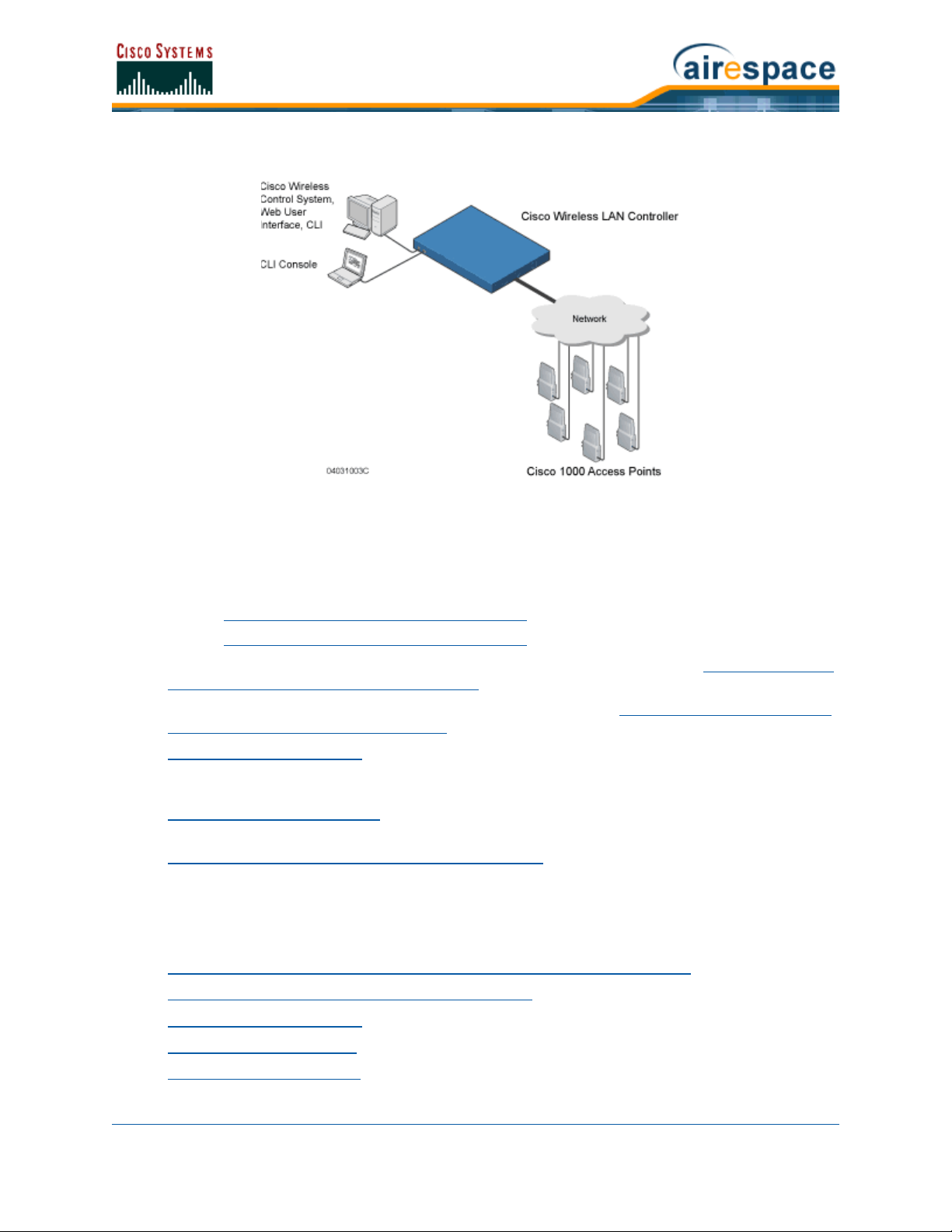
Figure - Cisco SWAN Components
The Product Guide uses unique software to provide WLAN access for wireless clients and to simultaneously provide an active wireless access control system that protects your wired and wireless
infrastructure from negligent and malicious wireless attacks. The Cisco SWAN uses the following
components:
• Cisco Wireless LAN Controllers:
- Cisco 2000 Series Wireless LAN Controllers
- Cisco 4100 Series Wireless LAN Controllers
• Cisco 1000 Series IEEE 802.11a/b/g lightweight access points, described in Cisco 1000 Series
IEEE 802.11a/b/g Lightweight Access Points.
• Cisco 1030 remote edge lightweight access points, described in Cisco 1030 IEEE 802.11a/b/g
Remote Edge Lightweight Access Points.
• Operating System Software Software which provides all the Data and intrusion detection
features and functions while operating the Cisco Wireless LAN Controllers and Cisco 1000 Series
lightweight access points.
• Cisco Wireless Control System, or which manages the Cisco SWAN, and which provides location
to the nearest Cisco 1000 Series lightweight access point.
• Cisco Wireless Control System with Location Services, which manages the Cisco SWAN, and
which provides location to within ten meters.
The Cisco SWAN provides wireless access services to data clients and provides intrusion protection. As
such, it supports the full suite of Cisco Structured Wireless-Aware Network features and functions.
Refer to the following for more information:
• Single-Cisco Wireless LAN Controller Wireless LAN Controller Deployments
• Multiple-Cisco Wireless LAN Controller Deployments
• Operating System Software
• Operating System Security
• Cisco SWAN Wired Security
3/11/05 About the Cisco Structured Wireless-Aware Network
OL-7426-02
Page 29

• Layer 2 and Layer 3 LWAPP Operation
• Radio Resource Management (RRM)
- Master Cisco Wireless LAN Controller
- Primary, Secondary, and Tertiary Cisco Wireless LAN Controllers
- Client Roaming
- External DHCP Servers
- Controller Mobility Group
- Cisco SWAN Wired Connections
- Cisco SWAN WLANs
- Transferring Files
- Power Over Ethernet
• Cisco Wireless LAN Controllers
• Cisco 1000 Series IEEE 802.11a/b/g Lightweight Access Points
• Rogue Access Points
• Cisco Wireless Control System
- Cisco WCS User Interface
- Cisco Wireless LAN Controller Autodiscovery
• Web User Interface
• Command Line Interface
Single-Cisco Wireless LAN Controller DeploymentsSingle-Cisco Wireless LAN Controller Wireless LAN Controller Deployments
As described in About the Cisco Structured Wireless-Aware Network, a standalone Cisco Wireless LAN
Controller can support Cisco 1000 Series lightweight access points across multiple floors and buildings
simultaneously, and supports the following features:
• Autodetecting and autoconfiguring Cisco 1000 Series lightweight access points as they are
added to the network, as described in Radio Resource Management (RRM).
• Full control of Cisco 1000 Series IEEE 802.11a/b/g Lightweight Access Points.
• Real-time control of system-wide WLAN Web, 802.1X, and IPSec security policies.
• Full control of up to 16 Cisco 1000 Series lightweight access point WLAN (SSID) policies, as
described in the Cisco 4100 Series Wireless LAN Controller Quick Start Guide
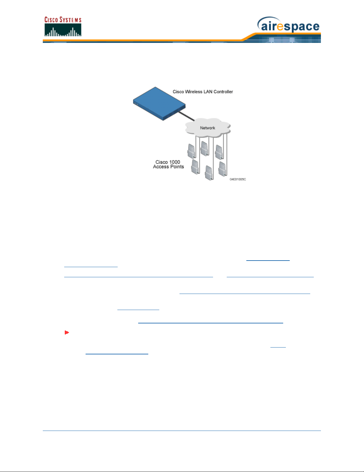
The following figures show a typical single Cisco Wireless LAN Controller deployed in Appliance Mode
• Cisco 1000 Series lightweight access points connect to Cisco Wireless LAN Controllers through
the network. The network equipment may or may not provide Power Over Ethernet to the
access points.
Note: Cisco Wireless LAN Controllers can connect through the Management Interface
to multiple subnets in the Network. This can be helpful, for instance, when Network
operators want to confine multiple VLANs to separate subnets using Oper-
ator-Defined Interfaces.
Note that the Cisco 4100 Series Wireless LAN Controller uses two redundant GigE connections
to bypass single network failures. At any given time one of the Cisco 4100 Series Wireless LAN
.
.
3/11/05 Single-Cisco Wireless LAN Controller Wireless LAN Controller Deployments
OL-7426-02
Page 30
Controller GigE connections is active and the other is passive. Upon a network failure, the
active connection becomes passive, and the passive connection becomes active.
Figure - Typical Cisco Wireless LAN Controller Deployment
Multiple-Cisco Wireless LAN Controller DeploymentsMultiple-Cisco Wireless LAN Controller Deployments
Each Cisco Wireless LAN Controller can support Cisco 1000 Series lightweight access points across
multiple floors and buildings simultaneously. Similarly, each Cisco Wireless LAN Controller can support
Cisco 1000 Series lightweight access points across multiple floors and buildings simultaneously.
However, full functionality of the Cisco SWAN is realized when it includes multiple Cisco Wireless LAN
Controllers. That is, a multiple-Cisco Wireless LAN Controller system has the following additional
features over a single-Cisco Wireless LAN Controller deployment:
• Autodetecting and autoconfiguring Cisco Wireless LAN Controller RF parameters as the Cisco
Wireless LAN Controllers are added to the network, as described in Radio Resource
Management (RRM).
• Same-Cisco Wireless LAN Controller (Layer 2) Roaming and Inter-Subnet (Layer 3) Roaming.
• Automatic Cisco 1000 Series lightweight access point failover to any redundant Cisco Wireless
LAN Controller with unused ports (refer to Cisco Wireless LAN Controller Failover Protection
The following figure shows a typical multiple-Cisco Wireless LAN Controller deployment, with the Cisco
Wireless LAN Controllers in Appliance Mode. The figure also shows an optional dedicated Service
Network, and the three physical connection types between the network and the Cisco Wireless LAN
Controllers, as further described in Network Connection to Cisco Wireless LAN Controllers
.
).
Note: Cisco Wireless LAN Controllers can connect through the Management Interface
to multiple subnets in the Network. This can be helpful, for instance, when Network
operators want to confine multiple VLANs to separate subnets using Oper-
ator-Defined Interfaces.
3/11/05 Multiple-Cisco Wireless LAN Controller Deployments
OL-7426-02
Page 31

Figure - Typical Multiple-Cisco Wireless LAN Controller Deployment
About the Operating System SoftwareOperating System Software
The Operating System Software controls Cisco Wireless LAN Controllers and Cisco 1000 Series lightweight access points. It includes full Operating System Security
(RRM) functions.
and Radio Resource Management
About Operating System SecurityOperating System Se curity
Operating System Security bundles Layer 1, Layer 2 and Layer 3 security components into a simple,
system-wide policy manager that creates independent security policies for each of up to 16 Cisco SWAN
WLANs. (Refer to Cisco SWAN WLANs
One of the barriers that made enterprises avoid deploying 802.11 networks was the inherent weakness
of 802.11 Static WEP (Wired Equivalent Privacy) encryption. Because WEP is so insecure, enterprises
have been looking for more secure solutions for business-critical traffic.
The 802.11 Static WEP weakness problem can be overcome using robust industry-standard security
solutions, such as:
• 802.1X dynamic keys with EAP (extensible authentication protocol).
• WPA (Wi-Fi protected access) dynamic keys. The Cisco SWAN WPA implementation includes:
- TKIP + Michael (temporal key integrity protocol + message integrity code checksum)
dynamic keys, or
3/11/05 Operating System Software
OL-7426-02
.)
Page 32

- WEP (Wired Equivalent Privacy) keys, with or without Pre-Shared key Passphrase.
• RSN with or without Pre-Shared key.
• Cranite FIPS140-2 compliant passthrough.
• Fortress FIPS140-2 compliant passthrough.
• Optional MAC Filtering.
The WEP problem can be further solved using industry-standard Layer 3 security solutions, such as:
• Terminated and passthrough VPNs (virtual private networks), and
• Terminated and passthrough L2TP (Layer Two Tunneling Protocol), which uses the IPSec (IP
Security) protocol.
• Terminated and pass-through IPSec (IP security) protocols. The terminated Cisco SWAN IPSec
implementation includes:
- IKE (internet key exchange),
- DH (Diffie-Hellman) groups, and
- Three optional levels of encryption: DES (ANSI X.3.92 data encryption standard), 3DES
(ANSI X9.52-1998 data encryption standard), or AES/CBC (advanced encryption
standard/cipher block chaining).
The Cisco SWAN IPSec implementation also includes industry-standard authentication using:
- MD5 (message digest algorithm), or
- SHA-1 (secure hash algorithm-1).
• The Cisco SWAN supports local and RADIUS MAC Address (media access control) filtering.
• The Cisco SWAN supports local and RADIUS user/password authentication.
• The Cisco SWAN also uses manual and automated Disabling to block access to network
services. In manual Disabling, the operator blocks access using client MAC addresses. In
automated Disabling, which is always active, the Operating System software automatically
blocks access to network services for an operator-defined period of time when a client fails to
authenticate for a fixed number of consecutive attempts. This can be used to deter brute-force
login attacks.
These and other Operating System Security
cation methods to ensure the highest possible security for your business-critical wireless LAN traffic.
For information about Cisco SWAN wired security, refer to Cisco SWAN Wired Security.
features use industry-standard authorization and authenti-
About Cisco SWAN Wired SecurityCisco SWAN Wired Sec urity
Many traditional Access Point vendors concentrate on security for the Wireless interface similar to that
described in the Operating System Security
Service Interfaces (Cisco Wireless Control System
Cisco Wireless LAN Controller-to-Cisco 1000 Series lightweight access point, and inter-Cisco Wireless
LAN Controller communications during device servicing and Client Roaming
includes built-in security.
Each Cisco Wireless LAN Controller and Cisco 1000 Series lightweight access point is manufactured with
a unique, signed X.509 certificate. This certificate is used to authenticate IPSec tunnels between
devices. These IPSec tunnels ensure secure communications for mobility and device servicing.
Cisco Wireless LAN Controllers and Cisco 1000 Series lightweight access points also use the signed
certificates to verify downloaded code before it is loaded, ensuring that hackers do not download
malicious code into any Cisco Wireless LAN Controller or Cisco 1000 Series lightweight access point.
section. However, for secure Cisco Wireless LAN Controller
, Web User Interface, and Command Line Interface),
, the Operating System
3/11/05 Cisco SWAN Wired Security
OL-7426-02
Page 33

For information about Cisco SWAN wireless security, refer to Operating System Security.
Layer 2 and Layer 3 LWAPP OperationLayer 2 and Layer 3 LWAPP Operation
The LWAPP communications between Cisco Wireless LAN Controllers and Cisco 1000 Series lightweight
access points can be conducted at ISO Data Link Layer 2 or Network Layer 3, when the connections are
made in Appliance Mode
Operational RequirementsOperational Requirements
The requirement for Layer 2 LWAPP communications is that the Cisco Wireless LAN Controllers and
Cisco 1000 Series lightweight access points must be connected through Layer 2 devices on the same
subnet. This is the default operational mode for the Cisco SWAN. Note that when the Cisco Wireless
LAN Controller and Cisco 1000 Series lightweight access points are on different subnets, these devices
must be operated in Layer 3 mode.
The requirement for Layer 3 LWAPP communications is that the Cisco Wireless LAN Controllers and
Cisco 1000 Series lightweight access points can be connected directly to each other, connected through
Layer 2 devices on the same subnet, or connected through Layer 3 devices across subnets.
Note that all Cisco Wireless LAN Controllers in an Controller Mobility Group
Layer 2 or Layer 3 mode, or you will defeat the Mobility software algorithm.
Configuration RequirementsConfiguration Requirements
When you are operating the Cisco SWAN in Layer 2 mode, you must configure a Management Interface
to control your Layer 2 communications.
When you are operating the Cisco SWAN in Layer 3 mode, you must configure a Management Interface
to control your Layer 2 communications, and an AP-Manager Interface to control Cisco 1000 Series
lightweight access point-to-Cisco Wireless LAN Controller Layer 3 communications.
.
must use the same LWAPP
About Radio Resource Management (RRM)Radio Resource Management (RRM)
Cisco is the only company to offer the powerful, comprehensive, and dynamic Radio Resource Management (RRM) solution to the 802.11 market. The Radio Resource Management (RRM) (also known as
Radio Resource Management, or RRM) allows Cisco Wireless LAN Controllers to continually monitor
their associated Cisco 1000 Series lightweight access points for the following information:
• Traffic Load -- How much total bandwidth is used for transmitting and receiving traffic. This
allows WLAN managers to track and plan network growth ahead of client demand.
• Interference -- How much traffic is coming from other 802.11 sources.
• Noise -- How much non-802.11 noise is interfering with the currently assigned channel.
• Coverage -- Received Signal Strength (RSSI) and Signal to Noise Ratio (SNR) for all clients.
• Nearby APs.
Using the collected information, the Radio Resource Management (RRM) can periodically reconfigure
the 802.11 RF network within operator-defined limits for best efficiency. To do this, Radio Resource
Management (RRM):
• Dynamically reassigns channels to increase capacity and performance, both within the same
Cisco Wireless LAN Controller and across multiple Cisco Wireless LAN Controllers.
• Adjusts the transmit power to balance coverage and capacity, both within the same Cisco
Wireless LAN Controller and across multiple Cisco Wireless LAN Controllers.
• Allows the operator to assign nearby Cisco 1000 Series lightweight access points into groups to
streamline Radio Resource Management (RRM) algorithm processing.
3/11/05 Layer 2 and Layer 3 LWAPP Operation
OL-7426-02
Page 34

• As new clients associate, they are load balanced across grouped Cisco 1000 Series lightweight
access points reporting to each Cisco Wireless LAN Controller. This is particularly important
when many clients converge in one spot (such as a conference room or auditorium), because
Radio Resource Management (RRM) can automatically force some subscribers to associate with
nearby APs, allowing higher throughput for all clients.
• Automatically detects and configures new Cisco 1000 Series lightweight access points as they
are added to the network. The Radio Resource Management (RRM) automatically adjusts
nearby Cisco 1000 Series lightweight access points to accommodate the increased coverage
and capacity.
• Automatically detects and configures new Cisco Wireless LAN Controllers as they are added to
the network. The Radio Resource Management (RRM) automatically distributes associated Cisco
1000 Series lightweight access points to maximize coverage and capacity.
• Detects and reports coverage holes, where clients consistently connect to a Cisco 1000 Series
lightweight access point at a very low signal strength.
• Automatically defines Cisco Wireless LAN Controller Groups within operator-defined Controller
Mobility Groups.
The Radio Resource Management (RRM) solution thus allows the operator to avoid the costs of
laborious historical data interpretation and individual Cisco 1000 Series lightweight access point
reconfiguration. The power control features of Radio Resource Management (RRM) ensure client satisfaction, and the coverage hole detection feature can alert the operator to the need for an additional (or
relocated) Cisco 1000 Series lightweight access point.
Note that the Radio Resource Management (RRM) uses separate monitoring and control for each of the
deployed networks: 802.11a and 802.11b/802.11g. Also note that the Radio Resource Management
(RRM) is automatically enabled, but can be customized or disabled for individual Cisco 1000 Series
lightweight access points.
Finally, for operators requiring easy manual configuration, the Radio Resource Management (RRM) can
recommend the best Cisco Radio settings, and then assign them on operator command.
The Radio Resource Management (RRM) controls produce a network that has optimal capacity, performance, and reliability. The Radio Resource Management (RRM) functions also free the operator from
having to continually monitor the network for noise and interference problems, which can be transient
and difficult to troubleshoot. Finally, the Radio Resource Management (RRM) controls ensure that
clients enjoy a seamless, trouble-free connection through the Cisco SWAN 802.11 network.
About the Master Cisco Wireless LAN ControllerMaster Cisco Wireless LAN Controller
When you are adding Cisco 1000 Series lightweight access points to a Multiple-Cisco Wireless LAN
Controller Deployments network configured in Appliance Mode, it is convenient to have all Cisco 1000
Series lightweight access points associate with one Master Cisco Wireless LAN Controller on the same
subnet. That way, the operator does not have to log into multiple Cisco Wireless LAN Controllers to find
out which Cisco Wireless LAN Controller newly added Cisco 1000 Series lightweight access points associated with.
One Cisco Wireless LAN Controller in each subnet can be assigned as the Master while adding Cisco
1000 Series lightweight access points. As long as a Master Cisco Wireless LAN Controller is active on
the same subnet, all new Cisco 1000 Series lightweight access points without a Primary, Secondary,
and Tertiary Cisco Wireless LAN Controllers assigned automatically attempt to associate with the Master
Cisco Wireless LAN Controller. This process is described in Cisco Wireless LAN Controller Failover
Protection.
The operator can monitor the Master Cisco Wireless LAN Controller using the Web User Interface
Cisco Wireless Control System
with the Master Cisco Wireless LAN Controllers configuration and assign a Primary, Secondary, and
3/11/05 Master Cisco Wireless LAN Controller
OL-7426-02
GUI, and watch as Cisco 1000 Series lightweight access points associate
or the
Page 35

Tertiary Cisco Wireless LAN Controllers to the Cisco 1000 Series lightweight access point, and reboot
the Cisco 1000 Series lightweight access point so it reassociates with its Primary, Secondary, or
Tertiary Cisco Wireless LAN Controller.
Note: Cisco 1000 Series lightweight access points without a Primary, Secondary, and
Tertiary Cisco Wireless LAN Controllers assigned always search for a Master Cisco
Wireless LAN Controller first upon reboot. After adding Cisco 1000 Series lightweight
access points through the Master, assign Primary, Secondary, and Tertiary Cisco
Wireless LAN Controllers to each Cisco 1000 Series lightweight access point.
Cisco recommends that you disable the Master setting on all Cisco Wireless LAN
Controllers after initial configuration.
Because the Master Cisco Wireless LAN Controller is normally not used in a deployed
network, the Master setting is automatically disabled upon reboot or OS code
upgrade.
About the Primary, Secondary, and Tertiary Cisco Wireless LAN ControllersPrimary, Secondary, and Tertiary Cisco
Wireless LAN Controllers
In Multiple-Cisco Wireless LAN Controller Deployments networks, Cisco 1000 Series lightweight access
points can associate with any Cisco Wireless LAN Controller on the same subnet. To ensure that each
Cisco 1000 Series lightweight access point associates with a particular Cisco Wireless LAN Controller,
the operator can assign Primary, Secondary, and Tertiary Cisco Wireless LAN Controllers to the Cisco
1000 Series lightweight access point.
When a Cisco 1000 Series lightweight access point is added to a network, it looks for its Primary,
Secondary, and Tertiary Cisco Wireless LAN Controllers first, then a Master Cisco Wireless LAN
Controller, then the least-loaded Cisco Wireless LAN Controller with available Cisco 1000 Series light-
weight access point ports. Refer to Cisco Wireless LAN Controller Failover Protection for more
information.
About Client RoamingClient Roaming
The Cisco SWAN supports seamless client roaming across Cisco 1000 Series lightweight access points
managed by the same Cisco Wireless LAN Controller, between Cisco Wireless LAN Controllers in the
same Controller Mobility Group
same Controller Mobility Group on different subnets. The following chapters describe the three modes
of roaming supported by the Cisco SWAN.
Same-Cisco Wireless LAN Controller (Layer 2) RoamingSame-Cisco Wireless LAN Controller (Layer 2) Roaming
Each Cisco Wireless LAN Controller supports same-Cisco Wireless LAN Controller client roaming across
Cisco 1000 Series lightweight access points managed by the same Cisco Wireless LAN Controller. This
roaming is transparent to the client, as the session is sustained and the client continues using the same
DHCP-assigned or client-assigned IP Address. The Cisco Wireless LAN Controller provides DHCP functionality be providing a relay function. Same-Cisco Wireless LAN Controller roaming is supported in
Single-Cisco Wireless LAN Controller Wireless LAN Controller Deployments
LAN Controller Deployments.
Inter-Cisco Wireless LAN Controller (Layer 2) RoamingInter-Cisco Wireless LAN Controller (Layer 2) Roaming
Similarly, in Multiple-Cisco Wireless LAN Controller Deployments, the Cisco SWAN supports client
roaming across Cisco 1000 Series lightweight access points managed by Cisco Wireless LAN Controllers
in the same Controller Mobility Group and on the same subnet. This roaming is also transparent to the
client, as the session is sustained and a tunnel between Cisco Wireless LAN Controllers allows the client
to continue using the same DHCP- or client-assigned IP Address as long as the session remains active.
Note that the tunnel is torn down and the client must reauthenticate when the client sends a DHCP
3/11/05 Primary, Secondary, and Tertiary Cisco Wireless LAN Controllers
OL-7426-02
on the same subnet, and across Cisco Wireless LAN Controllers in the
and Multiple-Cisco Wireless
Page 36

Discover with a 0.0.0.0 client IP Address or a 169.254.*.* client auto-IP Address, or when the operator-set session timeout is exceeded.
Note that the Cisco 1030 remote edge lightweight access points at a remote location must be on the
same subnet to support roaming.
Inter-Subnet (Layer 3) RoamingInter-Subnet (Layer 3) Roaming
Similarly, in Multiple-Cisco Wireless LAN Controller Deployments, the Cisco SWAN supports client
roaming across Cisco 1000 Series lightweight access points managed by Cisco Wireless LAN Controllers
in the same Controller Mobility Group on different subnets. This roaming is transparent to the client,
because the session is sustained and a tunnel between the Cisco Wireless LAN Controllers allows the
client to continue using the same DHCP-assigned or client-assigned IP Address as long as the session
remains active. Note that the tunnel is torn down and the client must reauthenticate when the client
sends a DHCP Discover with a 0.0.0.0 client IP Address or a 169.254.*.* client auto-IP Address, or
when the operator-set session timeout is exceeded.
Note that the Cisco 1030 remote edge lightweight access points at a remote location must be on the
same subnet to support roaming.
Special Case: Voice Over IP Telephone RoamingSpecial Case: Voice Over IP Telephone Roaming
802.11 VoIP telephones actively seek out associations with the strongest RF signal to ensure best
Quality of Service (QoS) and maximum throughput. The minimum VoIP telephone requirement of
20 millisecond or shorter latency time for the roaming handover is easily met by the Cisco SWAN, which
has an average handover latency of nine or fewer milliseconds.
This short latency period is controlled by Cisco Wireless LAN Controllers, rather than allowing independent APs to negotiate roaming handovers.
The Cisco SWAN supports 802.11 VoIP telephone roaming across Cisco 1000 Series lightweight access
points managed by Cisco Wireless LAN Controllers on different subnets, as long as the Cisco Wireless
LAN Controllers are in the same Controller Mobility Group. This roaming is transparent to the VoIP telephone, because the session is sustained and a tunnel between Cisco Wireless LAN Controllers allows the
VoIP telephone to continue using the same DHCP-assigned IP Address as long as the session remains
active. Note that the tunnel is torn down and the VoIP client must reauthenticate when the VoIP
telephone sends a DHCP Discover with a 0.0.0.0 VoIP telephone IP Address or a 169.254.*.* VoIP
telephone auto-IP Address, or when the operator-set session timeout is exceeded.
About Client LocationClient Location
The Cisco SWAN periodically determines client location and stores the locations in the Cisco WCS
database. To view the client location history, display the Cisco WCS Monitor Client <client> -
<vendor:MACaddr> page and select Recent Map (High Resolution) or Present Map (High Resolution).
About External DHCP ServersExternal DHCP Servers
The Operating System is designed to appear as a DHCP Relay to the network and as a DHCP Server to
clients with industry-standard external DHCP Servers that support DHCP Relay. This means that each
Cisco Wireless LAN Controller appears as a DHCP Relay agent to the DHCP Server. This also means that
the Cisco Wireless LAN Controller appears as a DHCP Server at the virtual IP Address to wireless clients.
Because the Cisco Wireless LAN Controller captures the client IP Address obtained from a DHCP Server,
it maintains the same IP Address for that client during same-Cisco Wireless LAN Controller, inter-Cisco
Wireless LAN Controller, and inter-subnet Client Roaming
3/11/05 Client Location
OL-7426-02
.
Page 37

Per-WLAN AssignmentPer-WLAN Assignment
All Cisco SWAN WLANs can be configured to use the same or different DHCP Servers, or no DHCP
Server. This allows operators considerable flexibility in configuring their Wireless LANs, as further
described in the Cisco SWAN WLANs
Note that Cisco SWAN WLANs that support Management over Wireless
(device servicing) clients to obtain an IP Address from a DHCP Server.
section.
must allow the management
Per-Interface AssignmentPer-Interface Assignment
• The Layer 2 Management Interface can be configured for a primary and secondary DHCP
server.
• The Layer 3 AP-Manager Interface can be configured for a primary and secondary DHCP server.
• Each of the Operator-Defined Interfaces can be configured for a primary and secondary DHCP
server.
• The Virtual Interface does not use DHCP servers.
• The Service-Port Interface can be configured to enable or disable DHCP servers.
Security ConsiderationsSecurity Considerations
For enhanced security, it is recommended that operators require all clients to obtain their IP Addresses
from a DHCP server. To enforce this requirement, all Cisco SWAN WLANs can be configured with a
‘DHCP Required’ setting and a valid DHCP Server IP Address, which disallows client static IP Addresses.
If a client associating with a WLAN with ‘DHCP Required’ set does not obtain its IP Address from the
designated DHCP Server, it is not allowed access to any network services.
Note that if ‘DHCP Required’ is selected, clients must obtain an IP address via DHCP. Any client with a
static IP address will not be allowed on the network. The Cisco Wireless LAN Controller monitors DHCP
traffic since it acts as a DHCP proxy for the clients.
If slightly less security is tolerable, operators can create Cisco SWAN WLANs
disabled and a valid DHCP Server IP Address. Clients then have the option of using a static IP Address
or obtaining an IP Address from the designated DHCP Server.
Operators are also allowed to create separate Cisco SWAN WLANs
DHCP Server IP Address of 0.0.0.0. These WLANs drop all DHCP requests and force clients to use a
static IP Address. Note that these WLANs do not support Management over Wireless.
with ‘DHCP Required’ disabled and a
with ‘DHCP Required’
About Controller Mobility GroupsController Mobility Group
Network operators can define Controller Mobility Groups to allow client roaming across groups of Cisco
Wireless LAN Controllers. Because the Cisco Wireless LAN Controllers in Multiple-Cisco Wireless LAN
Controller Deployments can detect each other across the network and over the air, it is important that
each enterprise, institution, and wireless internet service provider isolate their Cisco Wireless LAN
Controllers. The Operating System makes it easy for operators to create this isolation by allowing them
to assign a Controller Mobility Group Name to their Cisco Wireless LAN Controllers. This assignment can
be made using the Web User Interface
Interface.
Note that all the Cisco Wireless LAN Controllers in a Controller Mobility Group must use the same
LWAPP Layer 2 and Layer 3 LWAPP Operation, or you will defeat the Mobility software algorithm.
The following figure shows the results of creating Controller Mobility Group Names for two groups of
Cisco Wireless LAN Controllers. The Cisco Wireless LAN Controllers in the ABC Controller Mobility Group
recognize and communicate with each other through their Cisco 1000 Series IEEE 802.11a/b/g Light-
weight Access Points and Cisco 1030 IEEE 802.11a/b/g Remote Edge Lightweight Access Points and
through their shared subnets, but the ABC Controller Mobility Group tags the XYZ Cisco 1000 Series
3/11/05 Controller Mobility Group
OL-7426-02
, the Cisco Wireless Control System, or the Command Line
Page 38

lightweight access points as Rogue Access Points. Likewise, the Cisco Wireless LAN Controllers in the
XYZ Controller Mobility Group do not recognize or communicate with the Cisco Wireless LAN Controllers
in the ABC Controller Mobility Group. This feature ensures Controller Mobility Group isolation across the
network.
Figure - Typical Controller Mobility Group Name Application
CAUTION: Cisco recommends that you assign one set of VLANs for WLANs and a
different set of VLANs for Management Interfaces to ensure that Cisco Wireless LAN
Controllers properly route VLAN traffic.
The Controller Mobility Group feature can also be used to limit roaming between different floors, buildings, or campuses in the same enterprise by assigning different Controller Mobility Group names to
different Cisco Wireless LAN Controllers within the same wireless network.
CAUTION: The Cisco SWAN does not support simultaneous inter-switch and
inter-subnet roaming. Either install all the Controller Mobility Group members in the
same subnet or install all the Controller Mobility Group members in different subnets.
If enabled, Radio Resource Management (RRM)
Group.
operation is constrained within each Controller Mobility
Note: Because the Cisco Wireless LAN Controllers talk to each other when they are in
the same Controller Mobility Group, Cisco recommends that operators do not add
physically separated Cisco Wireless LAN Controllers to the same static Controller
Mobility Group to avoid unnecessary traffic on the network.
3/11/05 Controller Mobility Group
OL-7426-02
Page 39

About Cisco SWAN Wired ConnectionsCisco SWAN Wired Connections
The Cisco SWAN components communicate with each other using industry-standard Ethernet cables
and connectors. The following sections contain details of the Cisco SWAN wired connections.
Between Cisco Wireless LAN Controllers and Cisco 1000 Series Lightweight Access PointsBetween Cisco Wireless LAN
Controllers and Cisco 1000 Series Lightweight Access Points
The Cisco 4100 Series Wireless LAN Controller connects to the network using two fiber-optic GigE
cables: two redundant GigE connections to bypass single network failures. At any given time one of the
Cisco 4100 Series Wireless LAN Controller GigE connections is active and the other is passive. Upon a
network failure, the active connection becomes passive, and the passive connection becomes active.
Cisco 4100 Series Wireless LAN Controllers operate in Appliance Mode
any access points. The Cisco 1000 Series lightweight access points communicate with the Cisco 4100
Series Wireless LAN Controller through the network.
, and do not connect directly to
The standard CAT-5 cable can also be used to conduct power for the Cisco 1000 Series lightweight
access points from a network device equipped with Power Over Ethernet
distribution plan can be used to reduce the cost of individual AP power supplies and related cabling.
(PoE) capability. This power
Between Cisco 4100 Series Wireless LAN Controllers and Other Network DevicesBetween Cisco 4100 Series Wireless LAN Controllers and Other Network Devices
The Cisco 4100 Series Wireless LAN Controller connects to the network using two front-panel fiber-optic
GigE cables: two redundant GigE connections to bypass single network failures. At any given time one
of the Cisco 4100 Series Wireless LAN Controller GigE connections is active and the other is passive.
Upon a network failure, the active connection becomes passive, and the passive connection becomes
active.
About Cisco SWAN WLANsCisco SWAN WLANs
The Cisco SWAN can control up to 16 Wireless LANs for Cisco 1000 Series IEEE 802.11a/b/g Light-
weight Access Points. Each WLAN has a separate WLAN ID (1 through 16), a separate WLAN SSID
(WLAN Name), and can be assigned unique security policies.
The Cisco 1000 Series lightweight access points broadcast all active Cisco SWAN WLAN SSIDs and
enforce the policies defined for each WLAN.
Note that many enterprises use different WLANs to separate traffic for different sections or
departments.
CAUTION: Cisco recommends that you assign one set of VLANs for WLANs and a
different set of VLANs for Management Interfaces to ensure that Cisco Wireless LAN
Controllers properly route VLAN traffic.
3/11/05 Cisco SWAN Wired Connections
OL-7426-02
Page 40

If Management over Wireless is enabled across the Cisco SWAN, the Network operator can manage the
System across the enabled WLAN using CLI and Telnet (Command Line Interface), http/https (Web
User Interface), and SNMP (Cisco Wireless Control System).
To configure the Cisco SWAN WLANs, refer to Configuring WLANs.
About Access Control ListsAccess Control Lists
The Operating System allows you to define up to 64 Access Control Lists (ACLs), similar to standard
firewall Access Control Lists. Each ACL can have up to 64 Rules (filters).
Operators can use ACLs to control client access to multiple VPN servers within a given WLAN. If all the
clients on a WLAN must access a single VPN server, use the IPSec/VPN Gateway Passthrough setting in
IPSec Passthrough
After they are defined, the ACLs can be applied to the Management Interface
face, or any of the Operator-Defined Interfaces.
Refer to Access Control Lists > New
Lists in the Configuring the Cisco Wireless LAN Controllers sections for instructions on how to configure
the Access Control Lists.
, WLANs > Edit or Configure <IPaddr> > WLAN > Add From Template section.
, the AP-Manager Inter-
in the Web User Interface Online Help or Creating Access Control
About Identity NetworkingIdentity Networking
Cisco Wireless LAN Controllers can have the following parameters applied to all clients associating with
a particular WLAN: QoS, global or Interface-specific DHCP server, Layer 2 and Layer 3 Security Policies,
and default Interface (which includes physical port, VLAN and ACL assignments).
However, the Cisco Wireless LAN Controller can also have individual clients (MAC addresses) override
the preset WLAN parameters by using MAC Filtering or by Allowing AAA Override parameters. This
configuration can be used, for example, to have all company clients log into the corporate WLAN, and
then have clients connect using different QoS, DHCP server, Layer 2 and Layer 3 Security Policies, and
Interface (which includes physical port, VLAN and ACL assignments) settings on a per-MAC Address
basis.
When Network operators configure MAC Filtering for a client, they can assign a different VLAN to the
MAC Address, which can be used to have OS automatically reroute the client to the Management
Interface or any of the Operator-Defined Interfaces, each of which have their own VLAN, ACL, DHCP
server, and physical port assignments. This MAC Filtering can be used as a coarse version of AAA
Override, and normally takes precedence over any AAA (RADIUS or other) Override.
However, when Allow AAA Override
configured to return QoS and ACL on a per-MAC Address basis. Allow AAA Override gives the AAA
Override precedence over the MAC Filtering parameters set in the Cisco Wireless LAN Controller; if
there are no AAA Overrides available for a given MAC Address, the OS uses the MAC Filtering parameters already in the Cisco Wireless LAN Controller. This AAA (RADIUS or other) Override can be used as
a finer version of AAA Override, but only takes precedence over MAC Filtering when Allow AAA Override
is enabled.
Note that in all cases, the Override parameters (Operator-Defined Interface and QoS, for example)
must already be defined in the Cisco Wireless LAN Controller configuration.
In all cases, the OS will use QoS and ACL provided by the AAA server or MAC Filtering regardless of the
Layer 2 and/or Layer 3 authentication used.
Also note that the OS will only move clients from the default Cisco SWAN WLAN VLAN to a different
VLAN when configured for MAC filtering, 802.1X, and/or WPA Layer 2 authentication.
To configure the Cisco SWAN WLANs, refer to Configuring WLANs.
is enabled, the RADIUS (or other AAA) server can alternatively be
3/11/05 Access Control Lists
OL-7426-02
Page 41

About File TransfersTransferring Files
The Network operator can upload and download Operating System code, configuration, and certificate
files to and from a Cisco 2000 Series Wireless LAN Controller and/or Cisco 4100 Series Wireless LAN
Controller using CLI, Web User Interface, or Cisco Wireless Control System (Cisco WCS) commands.
• To use CLI commands, refer to Transferring Files To and From a Cisco Wireless LAN Controller.
• To use the Web User Interface, go to Using the Web User Interface.
• To use Cisco WCS commands, continue with Using the Cisco Wireless Control System.
About Power Over EthernetPower Over Ethernet
Cisco 1000 Series lightweight access points support 802.3af-compatible Power over Ethernet (PoE),
which can reduce the cost of discrete power supplies, additional wiring, conduits, outlets, and installer
time. PoE also frees installers from having to mount Cisco 1000 Series IEEE 802.11a/b/g Lightweight
Access Points, Cisco 1030 IEEE 802.11a/b/g Remote Edge Lightweight Access Points or other powered
equipment near AC outlets, providing greater flexibility in positioning Cisco 1000 Series lightweight
access points for maximum coverage.
When you are using PoE, the installer runs a single CAT-5 cable from each Cisco 1000 Series lightweight access point to a PoE power hub or to a Cisco Single-Line PoE Injector, described in Cisco 1000
Series Lightweight Access Point Models. When the PoE equipment determines that the Cisco 1000
Series lightweight access point is PoE-enabled, it sends 48 VDC over the unused pairs in the Ethernet
cable to power the access point.
The PoE cable length is limited by the 100BASE-T or 10BASE-T specification to 100 m or 200 m,
respectively.
Note: Cisco 1000 Series lightweight access points can receive power from any other
network device conforming to the IEEE 802.3af standard.
Note: Each Cisco 1000 Series lightweight access point can alternatively receive
power from one Cisco 1000 Series Lightweight Access Point External Power Supply.
Pico Cell FunctionalityPico Cell Functionality
Pico Cell functionality includes optimization of the OS to support this functionality as follows:
• The Cisco WCS Pico Cell Mode parameter reconfigures OS parameters, allowing OS to function
efficiently in pico cell deployments. Note that when the operator is deploying a pico cell network
the OS must also have more memory allocated (512 to 2048 MB) using the config database
size 2048 CLI command.
• Client mobility between multiple mobility domains when such exist.
• Addition of a WPA2 VFF extension to eliminate the need to re-key after every association. This
allows the re-use of existing PTK and GTK.
• With WPA2 PMK caching and VFF, the PMK cache is transferred as part of context transfer prior
to the authentication phase. This allows expedited handoffs to work for both intra- and
inter-Cisco Wireless LAN Controller roaming events.
• A beacon/probe response that allows a Cisco 1000 Series lightweight access point to indicate
which switch it is attached to so that reauthorization events will only occur when needed,
minimizing inter-switch handoffs and thus reducing CPU usage.
• Ability to change AP sensitivity for pico cells.
3/11/05 Transferring Files
OL-7426-02
Page 42

• Control of AP fall back behavior to optimize pico cell use.
• Heat map support for directional antennas.
• Specific control over blacklisting events
• Ability to configure and view basic LWAPP configuration elements using the AP’s CLI.
Intrusion Detection Service (IDS)Intrusion Detection Service (IDS)
Intrusion Detection Service includes the following:
• Sensing Clients probing for “ANY” SSID
• Sensing if AeS is being contained
• Notification of MiM Attacks, NetStumbler, Wellenreiter
• Management Frame Detection and RF Jamming Detection
• Airjack Detection (Spoofed Deauthorization detection)
• Broadcast Deauthorization Detection
• Null Probe Response Detection
• Fake AP Detection
• Detection of Weak WEP Encryption
• MAC Spoofing Detection
• AP Impersonation Detection
• Honeypot AP Detection
• Valid Station Protection
• Misconfigured AP Protection
• Rogue AP Detection
• AD-HOC Detection and Protection
• Wireless Bridge Detection
• Asleep Detection / Protection
3/11/05 Intrusion Detection Service (IDS)
OL-7426-02
Page 43

About Cisco Wireless LAN ControllersCisco Wireless LAN Controllers
Cisco 4100 Series Wireless LAN Controllers are enterprise-class high-performance wireless switching
platforms that support 802.11a and 802.11b/802.11g protocols. They operate under control of the
Operating System, which includes the Radio Resource Management (RRM), resulting in Cisco 2000
Series Wireless LAN Controllers that can automatically adjust to real-time changes in the 802.11 RF
environment. The Cisco 4100 Series Wireless LAN Controllers are built around high-performance
network and security hardware, resulting in highly reliable 802.11 enterprise networks with unparalleled security. Also see:
• Cisco 2000 Series Wireless LAN Controllers
• Cisco 4100 Series Wireless LAN Controllers
• Cisco Wireless LAN Controller Features
• Cisco 2000 Series Wireless LAN Controller Model Numbers
• Appliance Mode
• Distribution System Ports
• Management Interface
• AP-Manager Interface
• Operator-Defined Interfaces
• Virtual Interface
• Service Port
• Service-Port Interface
• Startup Wizard
• Cisco Wireless LAN Controller Memory
• Cisco Wireless LAN Controller Failover Protection
• Cisco Wireless LAN Controller Automatic Time Setting
• Cisco Wireless LAN Controller Time Zones
• Network Connection to Cisco Wireless LAN Controllers
• VPN/Enhanced Security Module
• Cisco SWAN Wired Connections
• Cisco 1000 Series IEEE 802.11a/b/g Lightweight Access Points
• Cisco 1030 IEEE 802.11a/b/g Remote Edge Lightweight Access Points
• Cisco SWAN WLANs
• Identity Networking
• Configuring the Cisco Wireless LAN Controllers
• Transferring Files To and From a Cisco Wireless LAN Controller
• Updating the Operating System Software
• Clearing Configurations
• Resetting the Cisco Wireless LAN Controller
• Cisco 4100 Series Wireless LAN Controller Quick Start Guide
3/11/05 Cisco Wireless LAN Controllers
OL-7426-02
Page 44

About Cisco 2000 Series Wireless LAN ControllersCisco 2000 Series Wireless LAN Controllers
The Cisco 2000 Series Wireless LAN Controller is part of the Cisco SWAN. The Cisco 2000 Series
Wireless LAN Controller controls up to six Cisco 1000 Series lightweight access points, making it ideal
for smaller enterprise and low-density applications. About the Cisco Structured Wireless-Aware Network
gives a comprehensive overview of the Cisco SWAN and the place of the Cisco 2000 Series Wireless
LAN Controller in that system.
The Cisco 2000 Series Wireless LAN Controller is a slim 9.5 x 6.0 x 1.6 in. (241 x 152 x 41 mm) chassis
that can be desktop or shelf mounted. The Cisco 2000 Series Wireless LAN Controller front panel has
one POWER LED and four sets of Ethernet LAN Port status LEDs, which indicate 10 MHz or 100 MHz
connections and transmit/receive Activity for the four corresponding back-panel Ethernet LAN connectors. The Cisco 2000 Series Wireless LAN Controller is shipped with four rubber mounting feet.
Cisco 4100 Series Wireless LAN ControllersCisco 4100 Series Wireless LAN Controllers
The Cisco 4100 Series Wireless LAN Controller is part of the Cisco SWAN. The Cisco 4100 Series
Wireless LAN Controller is one unit high, and communicates indirectly through the network (Appliance
Mode) with up to 12 (Model 4112), up to 24 (Model 4124), or up to 36 (Model 4136), associated Cisco
1000 Series IEEE 802.11a/b/g Lightweight Access Points, making it ideal for larger enterprise and
high-density applications.
Cisco 4100 Series Wireless LAN Controller support the Cisco SWAN as described in About the Cisco
Structured Wireless-Aware Network, which gives a comprehensive overview of the Cisco SWAN and the
place of the Cisco 4100 Series Wireless LAN Controllers in that system.
The following figure shows the Cisco 4100 Series Wireless LAN Controller, which has two redundant
front-panel SX/LC jacks.
Figure - Cisco 4100 Series Wireless LAN Controller
Cisco 4100 Series Wireless LAN Controllers can be factory-ordered with a VPN/Enhanced Security
Module (Crypto Card) to support VPN, IPSec and other processor-intensive tasks, and contain two
1000BASE-SX network connectors that allow the Cisco 4100 Series Wireless LAN Controller to communicate with the network at GigE (Gigabit Ethernet) speeds. The 1000BASE-SX network connectors
provide 100/1000 Mbps wired connections to a network through 850nM (SX) fiber-optic links using LC
physical connectors.
The two redundant GigE connections on the Cisco 4100 Series Wireless LAN Controller allow the Cisco
4100 Series Wireless LAN Controller to bypass single network failures. At any given time one of the
Cisco 4100 Series Wireless LAN Controller GigE connections is active and the other is passive. Upon a
network failure, the active connection becomes passive, and the passive connection becomes active.
Cisco Wireless LAN Controller FeaturesCisco Wireless LAN Controller Features
Cisco 2000 Series Wireless LAN Controllers connect to the associated Cisco 1000 Series lightweight
access points through the network.
After each Cisco 2000 Series Wireless LAN Controller is installed and configured, the Operating System
Radio Resource Management (RRM)
is activated, and the Operating System manages and controls
3/11/05 Cisco 2000 Series Wireless LAN Controllers
OL-7426-02
Page 45

associated Cisco 1000 Series lightweight access points with information about their relative positions,
IP Addresses, and MAC addresses. This information allows all Cisco Wireless LAN Controllers within
each Controller Mobility Group to constantly monitor and dynamically adjust the RF environment, maximizing performance, minimizing interference, and distributing the client load.
Cisco 2000 Series Wireless LAN Controllers communicate with Cisco 1000 Series lightweight access
points via 1000BASE-SX cables through the network. Note that the Cisco 2000 Series Wireless LAN
Controller uses two redundant GigE connections to bypass single network failures. At any given time
one of the Cisco 4100 Series Wireless LAN Controller GigE connections is active and the other is
passive. Upon a network failure, the active connection becomes passive, and the passive connection
becomes active.
The Cisco 2000 Series Wireless LAN Controller communicates with network via two 1000BASE-SX
Network Ports: the Cisco 2000 Series Wireless LAN Controller uses two redundant GigE connections to
bypass single network failures.
The network operator can control the Cisco Wireless LAN Controllers with the following Operating
System device interfaces:
• With optional Cisco Wireless Control System (Cisco WCS) inband or out-of-band via a
front-panel 10/100BASE-T Service port (Service Interface), or via the network (Management
Interface).
• With the built-in Command Line Interface via a serial RS232-C Console Port (direct connection),
or via the network (Telnet connection).
• With the built-in Web User Interface via a dedicated 10/100BASE-T Service port (recom-
mended), or via the network, using either http or https (http + SSL).
Refer to the following for more information about Cisco Wireless LAN Controllers:
• Cisco 2000 Series Wireless LAN Controllers
• Cisco 4100 Series Wireless LAN Controllers
• Cisco Wireless LAN Controller Features
• Cisco 2000 Series Wireless LAN Controller Model Numbers
• Cisco 4100 Series Wireless LAN Controller Model Numbers
• Appliance Mode
• Distribution System Ports
• Management Interface
• AP-Manager Interface
• Operator-Defined Interfaces
• Virtual Interface
• Service Port
• Service-Port Interface
• Startup Wizard
• Cisco Wireless LAN Controller Memory
• Cisco Wireless LAN Controller Failover Protection
• Cisco Wireless LAN Controller Automatic Time Setting
• Cisco Wireless LAN Controller Time Zones
• Network Connection to Cisco Wireless LAN Controllers
3/11/05 Cisco Wireless LAN Controller Features
OL-7426-02
Page 46

• VPN/Enhanced Security Module
• Cisco SWAN Wired Connections
• Cisco 1000 Series IEEE 802.11a/b/g Lightweight Access Points
• Cisco 1030 IEEE 802.11a/b/g Remote Edge Lightweight Access Points
• Cisco SWAN Wired Connections
• Cisco SWAN WLANs
• Configuring the Cisco Wireless LAN Controllers
• Transferring Files To and From a Cisco Wireless LAN Controller
• Updating the Operating System Software
• Clearing Configurations
• Resetting the Cisco Wireless LAN Controller
• Cisco 4100 Series Wireless LAN Controller Quick Start Guide
Cisco 2000 Series Wireless LAN Controller Model NumbersCisco 2000 Series Wireless LAN Controller Model Numbers
Cisco 2000 Series Wireless LAN Controller model number is as follows:
• AIR-WLC2006-K9 - The Cisco 2000 Series Wireless LAN Controller communicates with up to six
Cisco 1000 Series lightweight access points.
Note that the Cisco 2000 Series Wireless LAN Controllers come from the factory with tabletop mounting
feet.
The following upgrade is also available:
• Cisco 2000 Series Wireless LAN Controller Rack Mount Kit - Designed to mount a Cisco 2000
Series Wireless LAN Controller and its external Power Supply Module in a 19-inch (48.26 cm)
EIA equipment rack
Cisco 4100 Series Wireless LAN Controller Model NumbersCisco 4100 Series Wireless LAN Controller Model Numbers
Cisco 4100 Series Wireless LAN Controller model numbers are as follows:
• AIR-WLC4112-K9 - The Cisco 4100 Series Wireless LAN Controller uses two redundant GigE
connections to bypass single network failures, and communicates with up to 12 Cisco 1000
Series lightweight access points. That is, at any given time one of the Cisco 4100 Series
Wireless LAN Controller GigE connections is active and the other is passive. Upon a network
failure, the active connection becomes passive, and the passive connection becomes active.
Note that the 1000BASE-SX Network Adapters provide 100/1000 Mbps wired connections to a
network through 850nM (SX) fiber-optic links using LC physical connectors.
• AIR-WLC4124-K9 - The Cisco 4100 Series Wireless LAN Controller uses two redundant GigE
connections to bypass single network failures, and communicates with up to 24 Cisco 1000
Series lightweight access points.
• AIR-WLC4136-K9 - The Cisco 4100 Series Wireless LAN Controller uses two redundant GigE
connections to bypass single network failures, and communicates with up to 36 Cisco 1000
Series lightweight access points.
Note that all Cisco 4100 Series Wireless LAN Controller models come from the factory with 19-inch EIA
equipment rack flush-mount ears and tabletop mounting feet.
The following upgrade module is also available:
3/11/05 Cisco 2000 Series Wireless LAN Controller Model Numbers
OL-7426-02
Page 47

• AIR-VPN-4100 - VPN/Enhanced Security Module: Supports VPN, L2TP, IPSec and other
processor-intensive security options. This is a factory-orderable and field-installable option for
all Cisco 4100 Series Wireless LAN Controllers.
Appliance ModeAppliance Mode
All Cisco Wireless LAN Controllers operate in Appliance Mode. In Appliance Mode:
• The Cisco 2000 Series Wireless LAN Controller communicates with up to six Cisco 1000 Series
lightweight access points.
• The Model 4112 Cisco 4100 Series Wireless LAN Controller communicates with up to 12 Cisco
1000 Series lightweight access points.
• The Model 4124 Cisco 4100 Series Wireless LAN Controller communicates with up to 24 Cisco
1000 Series lightweight access points.
• The Model 4136 Cisco 4100 Series Wireless LAN Controller communicates with up to 36 Cisco
1000 Series lightweight access points.
Figure - Cisco Wireless LAN Controller Deployed in Appliance Mode
The Cisco Wireless LAN Controllers communicate with the network using one of the interfaces described
in the Network Connection to Cisco Wireless LAN Controllers
section.
About Distribution System PortsDistribution System Ports
A Distribution System (DS) port is a physical port (see Cisco SWAN Wired Connections) through which
the Cisco Wireless LAN Controller talks to the network and other access points. DS Ports are where
packets are exchanged between the Cisco SWAN WLANs and the rest of the network. The DS Ports can
also be used to communicate with Cisco 1000 Series lightweight access points.
• The Cisco 4100 Series Wireless LAN Controller supports a single Distribution System port
because it has two redundant 1000BASE-SX physical ports that must connect to the same
subnet.
Note: The Distribution System Port cannot be assigned to the dedicated Cisco 4100
Series Wireless LAN Controller front-panel Service Port.
As described in Layer 2 and Layer 3 LWAPP Operation
Layer 2 (same subnet) operation, the Distribution System must have one Management Interface
control all inter-Cisco Wireless LAN Controller, and all Cisco Wireless LAN Controller-to-Cisco 1000
3/11/05 Appliance Mode
OL-7426-02
, when the LWAPP communications are set to
to
Page 48

Series lightweight access point communications, regardless of the number of physical Distribution
System ports.
Also as described in Layer 2 and Layer 3 LWAPP Operation, when the LWAPP communications are set to
Layer 3 (different subnet) operation, the Distribution System must have one Management Interface to
control all inter-Cisco Wireless LAN Controller communications, and must have one AP-Manager
Interface to control all Cisco Wireless LAN Controller-to-Cisco 1000 Series lightweight access point
communications, regardless of the number of physical Distribution System ports.
Each physical Distribution System port can also have between one and 512 Operator-Defined Interfaces
assigned to it. Each Operator-Defined Interface is individually configured, and allows VLAN communications to exist on the Distribution System port(s).
Refer to the Configuring the Cisco Wireless LAN Controllers section for configuration instructions.
About the Management InterfaceManagement Interface
The logical Management Interface controls Layer 2 communications between Cisco Wireless LAN
Controllers and Cisco 1000 Series lightweight access points.
CAUTION: Cisco recommends that you assign one set of VLANs for WLANs and a
different set of VLANs for Management Interfaces to ensure that Cisco Wireless LAN
Controllers properly route VLAN traffic.
The Management Interface is assigned to one physical port (Cisco SWAN Wired Connections
which it communicates with other network devices and other access points. However, the Management
Interface can also communicate through all other physical ports except the front-panel Service Port as
follows:
), through
• Sends messages through the Layer 2 network to autodiscover and communicate with other
Cisco Wireless LAN Controllers through all physical ports except the front-panel Service Port
.
• Listens across the Layer 2 network for Cisco 1000 Series lightweight access point LWAPP polling
messages to autodiscover, associate with, and communicate with as many Cisco 1000 Series
lightweight access points as it can.
Note: Should a Cisco Wireless LAN Controller fail, its dropped Cisco 1000 Series
lightweight access points poll the network for another Cisco Wireless LAN Controller.
When an online Cisco Wireless LAN Controller has any remaining Cisco 1000 Series
lightweight access point ports, the Management Interface listens to the network for
Cisco 1000 Series lightweight access point polling messages to autodiscover,
associate with, and communicate with as many Cisco 1000 Series lightweight access
points as it can. Refer to the Cisco Wireless LAN Controller Failover Protection
for more information.
section
Note: The Management Interface cannot be assigned to the dedicated Cisco 4100
Series Wireless LAN Controller front-panel Service Port.
The Management Interface uses the burned-in Cisco Wireless LAN Controller Distribution System MAC
address, and must be configured for the following:
• VLAN assignment.
• Fixed IP Address, IP netmask, and default gateway.
• Physical port assignment.
• Primary and Secondary DHCP Servers.
• Access Control List, if required.
3/11/05 Management Interface
OL-7426-02
Page 49

Refer to the Configuring the Cisco Wireless LAN Controllers section for configuration instructions.
About the AP-Manager InterfaceAP-Manager Interface
The logical AP-Manager Interface controls Layer 3 communications between Cisco Wireless LAN
Controllers and Cisco 1000 Series lightweight access points.
The AP-Manager Interface is assigned to one physical port (Cisco SWAN Wired Connections
be on the same subnet and physical port as the Management Interface. The AP-Manager Interface can
communicate through any physical port except the front-panel Service Port as follows:
• Sends Layer 3 messages through the network to autodiscover and communicate with other
Cisco Wireless LAN Controllers.
• Listens across the network for Layer 3 Cisco 1000 Series lightweight access point LWAPP polling
messages to autodiscover, associate with, and communicate with as many Cisco 1000 Series
lightweight access points as it can.
Note: Should a Cisco Wireless LAN Controller fail, its dropped Cisco 1000 Series
lightweight access points poll the network for another Cisco Wireless LAN Controller.
When an online Cisco Wireless LAN Controller has any remaining Cisco 1000 Series
lightweight access point ports, the AP-Manager Interface listens to the network for
Cisco 1000 Series lightweight access point polling messages to autodiscover,
associate with, and communicate with as many Cisco 1000 Series lightweight access
points as it can. Refer to the Cisco Wireless LAN Controller Failover Protection
for more information.
Note: The AP-Manager Interface cannot be assigned to the dedicated Cisco 4100
Series Wireless LAN Controller front-panel Service Port.
), and can
section
The AP-Manager Interface must be configured for the following:
• VLAN assignment.
• Fixed IP Address (must be different than the Management Interface IP address, but must be on
the same subnet as the Management Interface), IP netmask, and default gateway.
• Physical port assignment.
• Primary and Secondary DHCP Servers.
• Access Control List, if required.
Refer to the Configuring the Cisco Wireless LAN Controllers
section for configuration instructions.
About Operator-Defined InterfacesOperator-Defined Interfaces
Each Cisco Wireless LAN Controller can support up to 512 Operator-Defined Interfaces. Each Operator-Defined Interface controls VLAN and other communications between Cisco Wireless LAN
Controllers and all other network devices connected to an individual physical port. Between one and
512 Operator-Defined Interfaces can be assigned to Cisco SWAN WLANs
Ports, the Layer 2 Management Interface, and the Layer 3 AP-Manager Interface.
Note: Operator-Defined Interfaces cannot be assigned to the dedicated Cisco 4100
Series Wireless LAN Controller front-panel Service Port.
CAUTION: Operator-Defined Interface names cannot have spaces in them. If an
Operator-Defined Interface name contains a space, you may not be able to edit its
configuration using the Command Line Interface
.
, physical Distribution System
3/11/05 AP-Manager Interface
OL-7426-02
Page 50

Each Operator-Defined Interface must be configured for the following:
• VLAN number.
• Fixed IP Address, IP netmask, and default gateway.
• Physical port assignment.
• Primary and Secondary DHCP Servers.
• Access Control List, if required.
Refer to the Configuring the Cisco Wireless LAN Controllers
section for configuration instructions.
About the Virtual InterfaceVirtual Interface
The Virtual Interface controls Layer 3 Security and Mobility manager communications for Cisco Wireless
LAN Controllers. It maintains the DNS Gateway hostname used by Layer 3 Security and Mobility
managers to verify the source of certificates when Layer 3 Web Auth is enabled.
The Virtual Interface must be configured for the following:
• Any fictitious, unassigned, unused Gateway IP Address.
• DNS Gateway Host Name.
Refer to the Configuring the Cisco Wireless LAN Controllers
section for configuration instructions.
About the Service PortService Po rt
The physical Service port on the Cisco 4100 Series Wireless LAN Controller front panel is a 10/
100BASE-T Ethernet port dedicated to Operating System service, and was formerly known as the
Management port. The Service Port is controlled by the Service-Port Interface.
The Service Port is configured with an IP Address, subnet mask, and IP assignment protocol different
from the Management Interface. This allows the operator to manage the Cisco 4100 Series Wireless
LAN Controller directly or through a dedicated Operating System service network, such as 10.1.2.x,
which can ensure Operating System device service access during network downtime.
Cisco created the Service port to remove the Cisco SWAN device service from the network data stream
to improve security and to provide a faster service connection.
Note that you cannot assign a Gateway to the Service port, so the port is not routable, unlike the other
front-panel 10/100BASE-T ports. However, you can set up dedicated routes to network management
devices.
Also note that the Service Port is not auto-sensing, unlike the other front-panel 10/100BASE-T ports:
you must use the correct straight-through or crossover Ethernet cable to communicate with the Service
Port.
Refer to the Configuring Other Ports and Parameters
Port.
for information on how to configure the Service
About the Service-Port InterfaceService-Port Interface
The Service-Port Interface controls communications through the dedicated Cisco 4100 Series Wireless
LAN Controller front-panel Service Port
Note: The Service-Port Interface can only be assigned to the dedicated Cisco 4100
Series Wireless LAN Controller front-panel Service Port.
The Service-Port Interface uses the burned-in Cisco 4100 Series Wireless LAN Controller Service Port
MAC address, and must be configured for the following:
3/11/05 Virtual Interface
OL-7426-02
.
Page 51

• Whether or not DHCP Protocol is activated.
• IP Address and IP netmask.
Refer to the Configuring the Cisco Wireless LAN Controllers
section for configuration instructions.
About the Startup WizardStartup Wizard
When a Cisco Wireless LAN Controller is powered up with a new factory Operating System software load
or after being reset to factory defaults, the bootup script runs the Startup Wizard, which prompts the
installer for initial configuration. The Startup Wizard:
• Ensures that the Cisco Wireless LAN Controller has a System Name, up to 32 characters.
• Adds an Administrative Username and Password, each up to 24 characters.
• Ensures that the Cisco 4100 Series Wireless LAN Controller can use Cisco WCS, Web User
Interface, or CLI to communicate with the Network Operator (either directly or indirectly)
through the Service Port
‘none’, IP Address and netmask. If you do not want to use the Service port, enter 0.0.0.0 for
the IP Address and netmask; this disables the Service Port.
• Ensures that the Cisco Wireless LAN Controller can communicate with the network (802.11
Distribution System) through the Management Interface by collecting a valid static IP Address,
netmask, default router IP address, VLAN identifier, and physical port assignment.
• Prompts for the IP address of the DHCP server used to supply IP addresses to clients, the Cisco
Wireless LAN Controller Management Interface, and optionally to the Service Port Interface.
• Asks for the LWAPP Transport Mode, described in Layer 2 and Layer 3 LWAPP Operation.
• Collects the Virtual Gateway IP Address; any fictitious, unassigned IP address (such as 1.1.1.1)
to be used by Layer 3 Security and Mobility managers.
• Allows you to enter the Controller Mobility Group (RF Group) Name.
• Collects the WLAN 1 802.11 SSID, or Network Name.
by accepting a valid IP configuration protocol (none or DHCP), and if
• Asks you to define whether or not clients can use static IP addresses. Yes = more convenient,
but lower security (session can be hijacked), clients can supply their own IP Address, better for
devices that cannot use DHCP. No = less convenient, higher security, clients must DHCP for an
IP Address, works well for Windows XP devices.
• If you want to configure a RADIUS server from the Startup Wizard, the RADIUS server IP
address, communication port, and Secret.
• Collects the Country Code. (Refer to Configuring the Cisco Wireless LAN Controllers and Cisco
SWAN Supported Country Codes.
• Enables and/or disables the 802.11a, 802.11b and 802.11g Cisco 1000 Series lightweight
access point networks.
• Enables or disables Radio Resource Management (RRM).
To use the Startup Wizard, refer to Using the Startup Wizard
.
About Cisco Wireless LAN Controller MemoryCisco Wireless LAN Controller Memory
The Cisco Wireless LAN Controllers contain two kinds of memory: volatile RAM, which holds the current,
active Cisco Wireless LAN Controller configuration, and NVRAM (non-volatile RAM), which holds the
reboot configuration. When you are configuring the Operating System in a Cisco Wireless LAN
Controller, you are modifying volatile RAM; you must save the configuration from the volatile RAM to
the NVRAM to ensure that the Cisco Wireless LAN Controller reboots using the current configuration.
3/11/05 Startup Wizard
OL-7426-02
Page 52

Knowing which memory you are modifying is important when you are:
• Using the Startup Wizard
• Clearing Configurations
• Saving Configurations
• Resetting the Cisco Wireless LAN Controller
• Logging Out of the CLI
Cisco Wireless LAN Controller Failover ProtectionCisco Wireless LAN Controller Failover Protection
The Cisco 2000 Series Wireless LAN Controller can associate with up to six Cisco 1000 Series lightweight access points. The Cisco 4100 Series Wireless LAN Controller can associate with up to 36 Cisco
1000 Series lightweight access points.
Note: During installation, Cisco recommends that you connect all Cisco 1000 Series
lightweight access points to a configured Cisco Wireless LAN Controller, and
configure each Cisco 1000 Series lightweight access point for final operation. This
step configures each Cisco 1000 Series lightweight access point for Primary,
Secondary, and Tertiary Cisco Wireless LAN Controllers, and allows it to store the
configured Controller Mobility Group information.
During failover recovery, the configured Cisco 1000 Series lightweight access points
obtain an IP address from the local DHCP server (only in Layer 3 Operation), attempt
to contact their Primary, Secondary, and Tertiary Cisco Wireless LAN Controllers, and
then attempt to contact the IP addresses of the other Cisco Wireless LAN Controllers
in the Controller Mobility Group. This will prevent the Cisco 1000 Series lightweight
access points from spending time sending out blind polling messages, resulting in a
faster recovery period.
In a multiple-Cisco Wireless LAN Controller Cisco SWAN (refer to Multiple-Cisco Wireless LAN Controller
Deployments), this means that if one Cisco Wireless LAN Controller fails, its dropped Cisco 1000 Series
lightweight access points reboot and do the following under direction of the Radio Resource Manage-
ment (RRM):
• Obtain an IP address from a local DHCP server (one on the local subnet).
• If the Cisco 1000 Series lightweight access point has a Primary, Secondary, and Tertiary Cisco
Wireless LAN Controllers assigned, it attempts to associate with that Cisco Wireless LAN
Controller.
• If the Cisco 1000 Series lightweight access point has no Primary, Secondary, or Tertiary Cisco
Wireless LAN Controllers assigned or if its Primary, Secondary, and Tertiary Cisco Wireless LAN
Controllers are unavailable, it attempts to associate with a Master Cisco Wireless LAN Controller
on the same subnet.
• If the Cisco 1000 Series lightweight access point finds no Master Cisco Wireless LAN Controller
on the same subnet, it attempts to contact stored Controller Mobility Group members by IP
address.
• Should none of the Controller Mobility Group members be available, and if the Cisco 1000
Series lightweight access point has no Primary, Secondary, and Tertiary Cisco Wireless LAN
Controllers assigned and there is no Master Cisco Wireless LAN Controller active, it attempts to
associate with the least-loaded Cisco Wireless LAN Controllers on the same subnet to respond
to its discovery messages with unused ports.
This means that when sufficient Cisco Wireless LAN Controllers are deployed in Appliance Mode
one Cisco Wireless LAN Controller fail, active Cisco 1000 Series lightweight access point client sessions
, should
3/11/05 Cisco Wireless LAN Controller Failover Protection
OL-7426-02
Page 53

are momentarily dropped while the dropped Cisco 1000 Series lightweight access point associates with
an unused port on another Cisco Wireless LAN Controller, allowing the client device to immediately
reassociate and reauthenticate.
Cisco Wireless LAN Controller Automatic Time SettingCisco Wireless LAN Controller Automatic Time Setting
Each Cisco Wireless LAN Controller can have its time manually set or can be configured to obtain the
current time from one or more Network Time Protocol (NTP) servers. Each NTP server IP address is
added to the Cisco Wireless LAN Controller database. Each Cisco Wireless LAN Controller searches for
an NTP server and obtains the current time upon reboot and at each user-defined polling interval (daily
to weekly).
Cisco Wireless LAN Controller Time ZonesCisco Wireless LAN Controller Time Zones
Each Cisco Wireless LAN Controller can have its time manually set or can be configured to obtain the
current time from one or more Network Time Protocol (NTP) servers. Each NTP server IP address is
added to the Cisco Wireless LAN Controller database. Each Cisco Wireless LAN Controller can search for
an NTP server and obtain the current time upon reboot and at each user-defined (daily to weekly)
polling interval.
This option can be configured in the Cisco WCS Configure <IPaddr> > Set Time
page.
Network Connection to Cisco Wireless LAN ControllersNetwork Connection to Cisco Wireless LAN Controllers
The Cisco Wireless LAN Controllers use the network as an 802.11 Distribution System.
Regardless of the Ethernet port type or speed, each Cisco Wireless LAN Controller monitors and
communicates with its related Cisco Wireless LAN Controllers across the network.
Cisco 2000 Series Wireless LAN ControllersCisco 2000 Series Wireless LAN Controllers
Cisco 2000 Series Wireless LAN Controllers can communicate with the network through any one of its
physical ports, as the logical Management Interface can be assigned to the one of the physical ports.
The physical port description follows:
• Up to four 10/100BASE-T cables can plug into the four back-panel connectors on the Cisco
2000 Series Wireless LAN Controller chassis.
3/11/05 Cisco Wireless LAN Controller Automatic Time Setting
OL-7426-02
Page 54

Figure - Physical Network Connections to the Cisco 2000 Series Wireless LAN Controller
Cisco 4100 Series Wireless LAN ControllersCisco 4100 Series Wireless LAN Controllers
Cisco 4100 Series Wireless LAN Controllers can communicate with the network through one or two
physical ports, and the logical Management Interface
The physical port description follows:
can be assigned to the one or two physical ports.
• Two GigE 1000BASE-SX fiber-optic cables can plug into the LC connectors on the front of the
Cisco 4100 Series Wireless LAN Controller, and they must be connected to the same subnet.
Note that the two GigE ports are redundant--the first port that becomes active is the master,
and the second port becomes the backup port. If the first connection fails, the standby
connection becomes the master, and the failed connection becomes the backup port.
Note that the 1000BASE-SX circuits provides 100/1000 Mbps wired connections to the network
through 850nM (SX) fiber-optic links using LC physical connectors.
3/11/05 Cisco 4100 Series Wireless LAN Controllers
OL-7426-02
Page 55

Figure - Physical Network Connections to the Cisco 4100 Series Wireless LAN Controller
VPN/Enhanced Security ModuleVPN/Enhanced Security Module
All Cisco 4100 Series Wireless LAN Controllers can be equipped with an optional VPN/Enhanced Security
Module (AS-Switch-ESM), which slides into the rear panel of the Cisco 4100 Series Wireless LAN
Controller. The VPN/Enhanced Security Module adds significant hardware encryption acceleration to the
Cisco 4100 Series Wireless LAN Controller, which enables the following through the Management
Interface:
• Sustain up to 1 Gbps throughput with Layer 2 and Layer 3 encryption enabled.
• Provide a built-in VPN server for mission-critical traffic.
• Support high-speed, processor-intensive encryption, such as L2TP, IPSec and 3DES.
The following figure shows the VPN/Enhanced Security Module sliding into the rear of a Cisco 4100
Series Wireless LAN Controller.
3/11/05 VPN/Enhanced Security Module
OL-7426-02
Page 56

Figure - Cisco 4100 Series Wireless LAN Controller VPN/Enhanced Security Module Location
3/11/05 VPN/Enhanced Security Module
OL-7426-02
Page 57

About Cisco 1000 Series IEEE 802.11a/b/g Lightweight Access PointsCisco
1000 Series IEEE 802.11a/b/g Lightweight Access Points
The Cisco 1000 Series lightweight access point is a part of the innovative Product Guide. When associated with an Cisco Wireless LAN Controllers as described below, the Cisco 1000 Series lightweight
access point provides advanced 802.11a and/or 802.11b/g Access Point functions in a single aesthetically pleasing plenum-rated enclosure. The following figure shows the two types of Cisco 1000 Series
lightweight access point: without and with connectors for external antennas.
Note that Cisco also offers Cisco 1030 remote edge lightweight access points, which are Cisco 1000
Series lightweight access points designed for remote deployment, Radio Resource Management (RRM)
control via a WAN link, and which includes connectors for external antennas.
Figure - Cisco 1000 Series Lightweight Access Point
Note that the Cisco 1000 Series lightweight access point is manufactured in a neutral color so it blends
into most environments (but can be painted), contains pairs of high-gain internal antennas for unidirectional (180-degree) or omnidirectional (360-degree) coverage (Cisco 1000 Series Lightweight Access
Point External and Internal Antennas), and is plenum-rated for installations in hanging ceiling spaces.
In the Cisco SWAN, most of the processing responsibility is removed from traditional SOHO (small
office, home office) APs and resides in the Cisco Wireless LAN Controllers.
Refer to the following for more information on Cisco 1000 Series lightweight access points:
• Cisco 1030 IEEE 802.11a/b/g Remote Edge Lightweight Access Points
• Cisco 1000 Series Lightweight Access Point Models
• Cisco 1000 Series Lightweight Access Point External and Internal Antennas
• Cisco 1000 Series Lightweight Access Point LEDs
3/11/05 Cisco 1000 Series IEEE 802.11a/b/g Lightweight Access Points
OL-7426-02
Page 58

• Cisco 1000 Series Lightweight Access Point Connectors
• Cisco 1000 Series Lightweight Access Point Power Requirements
• Cisco 1000 Series Lightweight Access Point External Power Supply
• Cisco 1000 Series Lightweight Access Point Mounting Options
• Cisco 1000 Series Lightweight Access Point Physical Security
• Cisco 1000 Series Lightweight Access Point Monitor Mode
• Cisco 1000 Series IEEE 802.11a/b/g Lightweight Access Point Deployment Guide
About Cisco 1030 IEEE 802.11a/b/g Remote Edge Lightweight Access PointsCisco 1030 IEEE 802.11a/b/g
Remote Edge Lightweight Access Points
The only exception to the general rule of Cisco 1000 Series IEEE 802.11a/b/g Lightweight Access Points
being continuously controlled by Cisco Wireless LAN Controllers is the Cisco 1000 Series Lightweight
Access Point (Cisco 1030 remote edge lightweight access point). The Cisco 1030 remote edge lightweight access point is intended to be located at a remote site, initially configured by a Cisco Wireless
LAN Controller, and normally controlled by a Cisco Wireless LAN Controller.
However, because the Cisco 1030 remote edge lightweight access point bridges the client data
(compared with other Cisco 1000 Series lightweight access points, which pass all client data through
their respective Cisco Wireless LAN Controller), if the WAN link breaks between the Cisco 1030 remote
edge lightweight access point and its Cisco Wireless LAN Controller, the Cisco 1030 remote edge lightweight access point continues transmitting WLAN 1 client data through other Cisco 1030 remote edge
lightweight access points on its local subnet. However, it cannot take advantage of features accessed
from the Cisco Wireless LAN Controller, such as establishing new VLANs, until communication is
reestablished.
The Cisco 1030 remote edge lightweight access point includes the traditional SOHO (small office, home
office) AP processing power, and thus can continue operating if the WAN link to its associated Cisco
Wireless LAN Controller fails. Because it is configured by its associated Cisco Wireless LAN Controller, it
has the same WLAN configuration as the rest of the Cisco SWAN (refer to Cisco SWAN WLANs
as it remains connected to its Cisco Wireless LAN Controller, it varies its transmit power and channel
selection under control of the Radio Resource Management (RRM)
location as any other Cisco 1000 Series lightweight access point.
Note that the Cisco 1030 remote edge lightweight access point can support multiple WLANs while it is
connected to its Cisco Wireless LAN Controller. However, when it loses connection to its Cisco Wireless
LAN Controller, it supports only one WLAN on its local subnet.
The following figure shows a typical Cisco 1030 remote edge lightweight access point configuration:
, and performs the same Rogue AP
). As long
3/11/05 Cisco 1030 IEEE 802.11a/b/g Remote Edge Ligh tweight Access Points
OL-7426-02
Page 59

Note that the Cisco 1030 remote edge lightweight access point must have a DHCP server available on
its local subnet, so it can obtain an IP address upon reboot. Also note that the Cisco 1030 remote edge
lightweight access points at each remote location must be on the same subnet to allow client roaming.
Refer to the following for more information on Cisco 1000 Series lightweight access points:
• Cisco 1000 Series IEEE 802.11a/b/g Lightweight Access Points
• Cisco 1000 Series Lightweight Access Point Models
• Cisco 1000 Series Lightweight Access Point External and Internal Antennas
• Cisco 1000 Series Lightweight Access Point LEDs
• Cisco 1000 Series Lightweight Access Point Connectors
• Cisco 1000 Series Lightweight Access Point Power Requirements
• Cisco 1000 Series Lightweight Access Point External Power Supply
• Cisco 1000 Series Lightweight Access Point Mounting Options
• Cisco 1000 Series Lightweight Access Point Physical Security
• Cisco 1000 Series Lightweight Access Point Monitor Mode
• Cisco 1000 Series IEEE 802.11a/b/g Lightweight Access Point Deployment Guide
• Internal-Antenna AP1010 Cisco 1000 Series IEEE 802.11a/b/g Lightweight Access Point Quick
Start Guide
• External-Antenna AP1020 and AP1030 Cisco 1000 Series IEEE 802.11a/b/g Lightweight Access
Point Quick Start Guide
3/11/05 Cisco 1030 IEEE 802.11a/b/g Remote Edge Ligh tweight Access Points
OL-7426-02
Page 60

About Cisco 1000 Series Lightweight Access Point ModelsCisco 1000 Series Lightweight Access Point Models
The Cisco 1000 Series lightweight access point includes one 802.11a and one 802.11b/g radio. The
Cisco 1000 Series lightweight access point is available in the following configurations:
• AIR-AP1010-A-K9, AIR-AP1010-C-K9, AIR-AP1010-E-K9, AIR-AP1010-J-K9, AIR-AP1010-N-K9,
and AIR-AP1010-S-K9 - AP1010 Cisco 1000 Series lightweight access point with one 802.11a
and one 802.11b/g radio and four high-gain internal antennas, one 5 GHz external antenna
adapter, and two 2.4 GHz external antenna adapters.
• AIR-AP1020-A-K9, AIR-AP1020-C-K9, AIR-AP1020-E-K9, AIR-AP1020-J-K9, AIR-AP1020-N-K9,
and AIR-AP1020-S-K9 - AP1020 Cisco 1000 Series lightweight access point with one 802.11a
and one 802.11b/g radio, four high-gain internal antennas, and no external antenna adapters.
• AIR-AP1030-A-K9, AIR-AP1030-C-K9, AIR-AP1030-E-K9, AIR-AP1030-J-K9, AIR-AP1030-N-K9,
and AIR-AP1030-S-K9 - AP1030 Cisco 1000 Series lightweight access point (Cisco 1030 remote
edge lightweight access point) with one 802.11a and one 802.11b/g radio and four high-gain
internal antennas, one 5 GHz external antenna adapter, and two 2.4 GHz external antenna
adapters.
Note: Refer to Cisco SWAN Supported Country Codes for the most recent information
on supported Regulatory Domains.
The Cisco 1000 Series lightweight access point is shipped with a color-coordinated ceiling mount base
and hanging-ceiling rail clips. You can also order projection- and flush-mount sheet metal wall
mounting bracket kits. The base, clips, and optional brackets allow quick mounting to ceiling or wall.
The Cisco 1000 Series lightweight access point can be powered by Power Over Ethernet
1000 Series Lightweight Access Point External Power Supply. The external power supply model is:
• AIR-PWR-1000 - Optional External 110-220 VAC-to-48 VDC Power Supply for any Cisco 1000
Series lightweight access point.
The Single Inline PoE injector model is:
• AIR-PWRINJ-1000AF - Optional Single 802.3af Inline Power over Ethernet Injector for any Cisco
1000 Series lightweight access point, powered by 90-250 VAC.
The projection and flush sheet metal wall mount bracket model is:
• AIR-ACC-WBRKT1000 - Optional sheet metal wall-mount bracket kit for any Cisco 1000 Series
lightweight access point. Includes one projection-mount and one flush-mount bracket per kit.
or by an Cisco
About Cisco 1000 Series Lightweight Access Point External and Internal Antennas
Cisco 1000 Series Lightweight Access Point External and Internal Antennas
Note: Cisco 1000 Series lightweight access points must use the factory-supplied
internal or external antennas to avoid violating FCC requirements and voiding the
user’s authority to operate the equipment. Refer to FCC Statements for Cisco 1000
Series Lightweight Access Points for detailed information.
The Cisco 1000 Series lightweight access point enclosure contains one 802.11a and/or one 802.11b/g
radio and four (two 802.11a and two 802.11b/g) high-gain antennas, which can be independently
enabled or disabled to produce a 180-degree sectorized or 360-degree omnidirectional coverage area.
Note that the wireless LAN operator can disable either one of each pair of the Cisco 1000 Series lightweight access point internal antennas to produce a 180-degree sectorized coverage area. This feature
can be useful, for instance, for outside-wall mounting locations where coverage is only desired inside
the building, and in a back-to-back arrangement that can allow twice as many clients in a given area.
3/11/05 Cisco 1000 Series Lightweight Access Point Models
OL-7426-02
Page 61

The following sections contain more information about Cisco 1000 Series lightweight access point
internal and external antennas:
• External Antenna Connectors
• Antenna Sectorization
• 802.11a Internal Antenna Patterns
• 802.11b/g Internal Antenna Patterns
External Antenna ConnectorsExternal Antenna Connectors
The AIR-AP1020-A-K9, AIR-AP1020-E-K9, AIR-AP1020-J-K9, AIR-AP1030-A-K9, AIR-AP1030-E-K9,
and AIR-AP1030-J-K9 Cisco 1000 Series lightweight access points have male reverse-polarity TNC
jacks for installations requiring factory-supplied external directional or high-gain antennas. The
external antenna option can create more flexibility in Cisco 1000 Series lightweight access point
antenna placement.
Note: The AIR-AP1010-A-K9, AIR-AP1010-E-K9, and AIR-AP1010-J-K9 Cisco 1000
Series lightweight access points are designed to be used exclusively with the internal
high-gain antennas, and have no jacks for external antennas.
Note that the 802.11b/g 2.4 GHz Left external antenna connector is associated with the internal Side A
antenna, and that the 2.4 GHz Right external antenna connector is associated with the internal Side B
antenna. When you have 802.11b/g diversity enabled, the Left external or Side A internal antennas are
diverse from the Right external or Side B internal antennas.
Also note that the 802.11a 5 GHz Left external antenna connector is separate from the internal
antennas, and adds diversity to the 802.11a transmit and receive path. Note that no external 802.11a
antennas are certified in FCC-regulated areas, but external 802.11a antennas may be certified for use
in other countries.
Antenna SectorizationAntenna Sectorization
Note that the Cisco SWAN supports Antenna Sectorization, which can be used to increase the number of
clients and/or client throughput in a given air space. Installers can mount two Cisco 1000 Series lightweight access points back-to-back, and the Network operator can disable the second antenna in both
Cisco 1000 Series lightweight access points to create a 360-degree coverage area with two sectors.
Installers can also mount Cisco 1000 Series lightweight access points on the periphery of a building and
disable the Side B internal antennas. This configuration can be used to supply service to the building
interior without extending coverage to the parking lot, at the cost of eliminating the internal antenna
diversity function.
802.11a Internal Antenna Patterns802.11a Internal Antenna Patterns
The Cisco 1000 Series lightweight access points contain one 802.11a radio, which drives two fully
enclosed high-gain antennas that provide a large 360-degree coverage area. The two internal antennas
are used at the same time to provide a 360-degree omnidirectional coverage area, or either antenna
can be disabled to provide a 180-degree sectorized coverage area.
When equipped with an optional factory-supplied external antenna, the 802.11a Cisco Radio supports
receive and transmit diversity between the internal antennas and the external antenna. The diversity
function provided by Cisco Radios can result in lower multipath fading, fewer packet retransmissions,
and higher client throughput.
3/11/05 Cisco 1000 Series Lightweight Access Point External and Internal Antennas
OL-7426-02
Page 62

Figure - Cisco 1000 Series Lightweight Access Point 802.11a OMNI (Dual Internal) Azimuth Antenna Gain Pattern
Figure - Cisco 1000 Series Lightweight Access Point 802.11a OMNI (Dual Internal) Elevation Antenna Gain Pattern
3/11/05 Cisco 1000 Series Lightweight Access Point External and Internal Antennas
OL-7426-02
Page 63

Figure - Cisco 1000 Series Lightweight Access Point 802.11a Sectorized (Single Internal) Azimuth Antenna Gain
Pattern
Figure - Cisco 1000 Series Lightweight Access Point 802.11a Sectorized (Single Internal) Elevation Antenna Gain
Pattern
3/11/05 Cisco 1000 Series Lightweight Access Point External and Internal Antennas
OL-7426-02
Page 64

802.11b/g Internal Antenna Patterns802.11b/g Internal Antenna Patterns
The Cisco 1000 Series lightweight access points contain one 802.11b/g radio which drives two fully
enclosed high-gain antennas which can provide a large 360-degree coverage area. The two internal
antennas can be used at the same time to provide a 360-degree omnidirectional coverage area, or
either antenna can be disabled to provide a 180-degrees sectorized coverage area.
The 802.11b/g Cisco Radios support receive and transmit diversity between the internal antennas and/
or optional factory-supplied external antennas.
Figure - Cisco 1000 Series Lightweight Access Point 802.11b/g OMNI (Dual Internal) Azimuth Antenna Gain Pattern
Figure - Cisco 1000 Series Lightweight Access Point 802.11b/g OMNI (Dual Internal) Elevation Antenna Gain Pattern
3/11/05 Cisco 1000 Series Lightweight Access Point External and Internal Antennas
OL-7426-02
Page 65

Figure - Cisco 1000 Series Lightweight Access Point 802.11b/g Sectorized (Single Internal) Azimuth Antenna Gain
Pattern
Figure - Cisco 1000 Series Lightweight Access Point 802.11b/g Sectorized (Single Internal) Elevation Antenna Gain
Pattern
About Cisco 1000 Series Lightweight Access Point LEDsCisco 1000 Series Lightweight Access Point LEDs
Each Cisco 1000 Series lightweight access point is equipped with four LEDs across the top of the case.
They can be viewed from nearly any angle. The LEDs indicate power and fault status, 2.4 GHz
(802.11b/g) Cisco Radio activity, and 5 GHz (802.11a) Cisco Radio activity.
This LED display allows the wireless LAN manager to quickly monitor the Cisco 1000 Series lightweight
access point status. For more detailed troubleshooting instructions, refer to the Troubleshooting Tips
section.
3/11/05 Cisco 1000 Series Lightweight Access Point LEDs
OL-7426-02
Page 66

About Cisco 1000 Series Lightweight Access Point ConnectorsCisco 1000 Series Lightweight Access Point Con ne ct o rs
The AIR-AP1020-A-K9, AIR-AP1020-E-K9, AIR-AP1020-J-K9, AIR-AP1030-A-K9, AIR-AP1030-E-K9,
and AIR-AP1030-J-K9 Cisco 1000 Series lightweight access points have the following external
connectors:
• One RJ-45 Ethernet jack, used for connecting the Cisco 1000 Series lightweight access point to
the network.
• One 48 VDC power input jack, used to plug in an optional factory-supplied external power
adapter.
• Three male reverse-polarity TNC antenna jacks, used to plug optional external antennas into
the Cisco 1000 Series lightweight access point: two for an 802.11b/g radio, and one for an
802.11a radio.
Note: The AIR-AP1010-A-K9, AIR-AP1010-E-K9, and AIR-AP1010-J-K9 Cisco 1000
Series lightweight access points are designed to be used exclusively with the internal
high-gain antennas, and have no jacks for external antennas.
Figure - Cisco 1000 Series Lightweight Access Point External Antenna Connectors
3/11/05 Cisco 1000 Series Lightweight Access Point Connectors
OL-7426-02
Page 67

Note that the Cisco 1000 Series lightweight access point can receive power over the CAT-5 cable from
network equipment. Refer to Power Over Ethernet for more information about this option.
The Cisco 1000 Series lightweight access point can be powered from an optional factory-supplied
external AC-to-48 VDC power adapter. If you are powering the Cisco 1000 Series lightweight access
point using an external adapter, plug the adapter into the 48 VDC power jack on the side of the Cisco
1000 Series lightweight access point.
The Cisco 1000 Series lightweight access point includes two 802.11a and two 802.11b/g high-gain
internal antennas, which provide omnidirectional coverage. However, some Cisco 1000 Series lightweight access point models and the Cisco 1030 remote edge lightweight access point can also use
optional factory-supplied external high-gain and/or directional antennas, as described in Cisco 1000
Series Lightweight Access Point External and Internal Antennas. When you are using external antennas,
plug them into the male reverse-polarity TNC jacks on the side of the AIR-AP1020-A-K9,
AIR-AP1020-E-K9, AIR-AP1020-J-K9, AIR-AP1030-A-K9, AIR-AP1030-E-K9, and AIR-AP1030-J-K9
Cisco 1000 Series lightweight access points as described in the Internal-Antenna AP1010 Cisco 1000
Series IEEE 802.11a/b/g Lightweight Access Point Quick Start Guide.
Note: The Cisco 1000 Series lightweight access points must use the factory-supplied
internal or external antennas to avoid violating FCC regulations and voiding the
user’s authority to operate the equipment, as described in FCC Statements for Cisco
1000 Series Lightweight Access Points.
About Cisco 1000 Series Lightweight Access Point Power RequirementsCisco 1000 Series Lightweight Access Point Power
Requirements
Each Cisco 1000 Series lightweight access point requires a 48 VDC nominal (between 38 and 57 VDC)
power source capable of providing 7 Watts. The polarity of the DC source does not matter because the
Cisco 1000 Series lightweight access point can use either a +48 VDC or a -48 VDC nominal source.
Cisco 1000 Series lightweight access points can receive power from the Cisco 1000 Series Lightweight
Access Point External Power Supply (which draws power from a 110-220 VAC electrical outlet) plugged
into the side of the Cisco 1000 Series lightweight access point case, or from Power Over Ethernet.
3/11/05 Cisco 1000 Series Lightweight Access Point Power Requirements
OL-7426-02
Page 68

Figure - Typical Cisco 1000 Series Lightweight Access Point External Power Supply
For more information about the Cisco 1000 Series lightweight access point specifications and capacities,
refer to Specifications
, available in the Cisco SWAN Marketing Literature.
About Cisco 1000 Series Lightweight Access Point External Power SupplyCisco 1000 Series Lightweight Access Point
External Power Supply
The Cisco 1000 Series lightweight access point can receive power from an external
110-220 VAC-to-48 VDC power supply or from Power Over Ethernet equipment.
The external power supply (AS-AP-PWR) plugs into a secure 110 through 220 VAC electrical outlet. The
converter produces the required 48 VDC output (Cisco 1000 Series Lightweight Access Point Power
Requirements) for the Cisco 1000 Series lightweight access point. The converter output feeds into the
side of the Cisco 1000 Series lightweight access point through a 48 VDC jack (Cisco 1000 Series Light-
weight Access Point Connectors).
Note that the AS-AP-PWR external power supply can be ordered with country-specific electrical outlet
power cords. Contact Cisco when ordering to receive the correct power cord.
About Cisco 1000 Series Lightweight Access Point Mounting OptionsCisco 1000 Series Lightweight Access Point Mounting Options
Refer to the Internal-Antenna AP1010 Cisco 1000 Series IEEE 802.11a/b/g Lightweight Access Point
Quick Start Guide for the Cisco 1000 Series lightweight access point mounting options.
About Cisco 1000 Series Lightweight Access Point Physical SecurityCisco 1000 Series Lightweight Access Point Physical Security
The side of the Cisco 1000 Series lightweight access point housing includes a slot for a Kensington
MicroSaver Security Cable. You can use any MicroSaver Security Cable to ensure that your Cisco 1000
Series lightweight access point stays where you mounted it!
Refer to the Kensington website for more information about their security products, or to the
Internal-Antenna AP1010 Cisco 1000 Series IEEE 802.11a/b/g Lightweight Access Point Quick Start
Guide for installation instructions.
3/11/05 Cisco 1000 Series Lightweight Access Point External Power Supply
OL-7426-02
Page 69

About Cisco 1000 Series Lightweight Access Point Monitor ModeCisco 1000 Series Lightweight Access Point Monitor Mod e
The Cisco 1000 Series lightweight access points and Cisco Wireless LAN Controllers are capable of
performing Rogue AP detection and containment while providing regular service. The Rogue AP
detection is performed across all 801.11 channels, regardless of the Country Code selected. (Refer to
Cisco SWAN Supported Country Codes
However, if the administrator would prefer to dedicate specific Cisco 1000 Series lightweight access
points to Rogue AP detection and containment, the Monitor mode should be enabled for individual Cisco
1000 Series lightweight access points.
The Monitor function is set for all 802.11 Cisco Radios on a per-Cisco 1000 Series lightweight access
point basis in the Cisco APs > Details
for more details).
section in the Web User Interface Online Help.
3/11/05 Cisco 1000 Series Lightweight Access Point Monitor Mode
OL-7426-02
Page 70

About Rogue Access PointsRogue Access Points
Because they are inexpensive and readily available, employees are plugging unauthorized rogue access
points (Rogue APs) into existing LANs and building ad hoc wireless networks without IT department
knowledge or consent.
These Rogue APs can be a serious breach of network security, because they can be plugged into a
network port behind the corporate firewall. Because employees generally do not enable any security
settings on the Rogue APs, it is easy for unauthorized users to use the access point to intercept network
traffic and hijack client sessions. Even more alarming, wireless users and war chalkers frequently
publish unsecure access point locations, increasing the odds of having the enterprise security breached.
Rather than using a person with a scanner to manually detect Rogue APs, the Cisco SWAN automatically collects information on Rogue APs detected by its managed Cisco 1000 Series IEEE 802.11a/b/g
Lightweight Access Points, by MAC and IP Address, and allows the Network operator to locate, tag and
monitor them as described in the Detecting and Locating Rogue Access Points section. The Operating
System can also be used to discourage Rogue AP clients by sending them deauthenticate and disassociate messages from one to four Cisco 1000 Series lightweight access points. Finally, the Operating
System can be used to automatically discourage all clients attempting to authenticate with all
Rogue APs on the enterprise subnet. Because this real-time detection is automated, it saves labor costs
used for detecting and monitoring Rogue APs while vastly improving LAN security.
Note that the peer-to-peer, or ad-hoc, clients can also be considered Rogue APs. See also Rogue AP Location, Tagging and Containment
Rogue AP Location, Tagging and ContainmentRogue AP Location, Tagging and Containment
This built-in detection, tagging, monitoring and containment capability allows system administrators to
take required actions:
• Locate Rogue APs as described in Detecting and Locating Rogue Access Points.
• Receive new Rogue AP notifications, eliminating hallway scans.
.
• Monitor unknown Rogue APs until they are eliminated or acknowledged.
• Determine the closest authorized Cisco 1000 Series IEEE 802.11a/b/g Lightweight Access
Points, making directed scans faster and more effective.
• Contain Rogue APs by sending their clients deauthenticate and disassociate messages from one
to four Cisco 1000 Series lightweight access points. This containment can be done for individual
Rogue APs by MAC address, or can be mandated for all Rogue APs connected to the enterprise
subnet.
• Tag Rogue APs:
- Acknowledge Rogue APs when they are outside of the LAN and do not compromise the
LAN or WLAN security.
- Accept Rogue APs when they do not compromise the LAN or WLAN security.
- Tag Rogue APs as unknown until they are eliminated or acknowledged.
- Tag Rogue APs as contained and discourage clients from associating with the Rogue AP
by having between one and four Cisco 1000 Series lightweight access points transmit
deauthenticate and disassociate messages to all Rogue AP clients. This function
contains all active channels on the same Rogue AP.
Rogue Detector mode detects whether or not a rogue is on a trusted network. It does not provide RF
service of any kind, but rather receives periodic rogue reports from the switch, and sniffs all ARP
packets. If it finds a match between an ARP request and a MAC address it receives from the switch, it
generates a rogue alert to the switch.
3/11/05 Rogue Access Points
OL-7426-02
Page 71

To facilitate automated Rogue AP detection in a crowded RF space, Cisco 1000 Series lightweight
access points can be configured to operate in Cisco 1000 Series Lightweight Access Point Monitor Mode,
allowing monitoring without creating unnecessary interference.
3/11/05 Rogue AP Location, Tagging and Containment
OL-7426-02
Page 72

About the Cisco Wireless Control SystemCisco Wireless Control System
The Cisco Wireless Control System (Cisco WCS) is the Cisco Structured Wireless-Aware Network
network management tool that adds to the capabilities of the Web User Interface
Line Interface, moving from individual Cisco Wireless LAN Controllers to a network of Cisco Wireless
LAN Controllers. The Cisco Wireless Control System runs on Windows 2000, Windows 2003, and Red
Hat Enterprise Linux ES Server workstations.
The Cisco WCS includes the same configuration, performance monitoring, security, fault management,
and accounting options available at the Cisco Wireless LAN Controller level, but adds a graphical view of
multiple Cisco Wireless LAN Controllers and managed Cisco 1000 Series lightweight access points.
The Cisco WCS consists of Cisco WCS modules which support different feature levels:
• Cisco Wireless Control System, which includes wireless client data access, Rogue AP
containment functions, Cisco SWAN monitoring and control, and which allows Client and
Rogue AP location to the nearest Cisco 1000 Series lightweight access point.
• Cisco Wireless Control System with Location Services, which performs the same functions as
the Cisco Wireless Control System
location to within 10 meters.
These features are listed in the following table:
, and which allows high-accuracy Rogue AP and client
and the Command
Cisco
Features
Location and Tracking:
• Low-Resolution Client Location Yes -
• High-Resolution Client Location - Yes
• Low-Resolution Rogue AP Location Yes -
• High-Resolution Rogue AP Location - Yes
Client Data Services, Security and Monitoring:
• Client Access via Cisco 1000 Series lightweight access points Yes Yes
• Multiple WLANs (Individual SSIDs and Policies) Yes Yes
Rogue AP Detecting and Containing using Cisco 1000 Series lightweight
access points
802.11a/b/g Bands Yes Yes
Radio Resource Management (RRM) (real-time assigning channels, and
detecting and containing rogue APs)
Radio Resource Management (RRM) (real-time detecting and avoiding
interference, controlling transmit power, assigning channels, managing
client mobility, distributing client load, and detecting coverage holes)
WCS
Base
Software
Yes Yes
Yes Yes
Yes Yes
Cisco
WCS
Location
Software
Automated Software and Configuration Updates Yes Yes
Wireless Intrusion Protection Yes Yes
3/11/05 Cisco Wireless Control System
OL-7426-02
Page 73

Cisco
Features
Global and Individual AP Security Policies Yes Yes
Monitors and Configures Cisco Wireless LAN Controllers Yes Yes
Supported Workstations:
• Windows 2000 or Windows 2003 Yes Yes
• Red Hat Enterprise Linux ES Server Yes Yes
The Cisco Wireless Control System runs on Windows 2000 or 2003 and Red Hat Enterprise Linux ES
Server workstations. The Windows Cisco WCS can run as a normal Windows application, or can be
installed as a service, which runs continuously and resumes running after a reboot. The Linux Cisco
WCS always runs as a normal Linux application.
The Cisco WCS User Interface allows Network operators to control all permitted Cisco SWAN configuration, monitoring, and control functions through Internet Explorer 6.0 on a Windows workstation (or
other) web browser window. The Network operator permissions are defined by the Cisco WCS administrator in the Cisco WCS User Interface using the Cisco WCS User Interface Admin tab, which allows the
Cisco WCS administrator to administer user accounts and schedule periodic maintenance tasks.
Cisco WCS simplifies Cisco Wireless LAN Controller configuring and monitoring while decreasing data
entry errors with the Cisco Wireless LAN Controller Autodiscovery
industry-standard SNMP protocol to communicate with Cisco Wireless LAN Controllers.
algorithm. The Cisco WCS uses
WCS
Base
Software
Cisco
WCS
Location
Software
About the Cisco Wireless Control SystemCisco Wireless Control System
The Cisco Wireless Control System supports wireless client data access, Rogue AP detection and
containment functions, Cisco SWAN monitoring and control, and includes graphical views of the
following:
• Auto-discovery of Cisco 1000 Series IEEE 802.11a/b/g Lightweight Access Points as they
associate with Cisco Wireless LAN Controllers.
• Auto-discovery, and containment or notification of Rogue Access Points.
• Map-based organization of Access Point coverage areas, helpful when the enterprise spans
more than one geographical area. (Refer to Using Cisco WCS and Checking the Cisco SWAN
Network Summary.)
• User-supplied Campus, Building and Floor graphics, which show the following:
- Locations and status of managed access points. (Refer to Adding a Cisco Wireless LAN
Controller to Cisco WCS.)
- Locations of Rogue APs, based on signal strength received by nearest managed Cisco
1000 Series lightweight access points. (Refer to Detecting and Locating Rogue Access
Points.)
- Coverage hole alarm information for Cisco 1000 Series lightweight access points is
based on received signal strength from clients. This information appears in a tabular
rather than map format. (Refer to Finding Coverage Holes
- RF coverage maps.
• System-wide control:
.)
3/11/05 Cisco Wireless Control System
OL-7426-02
Page 74

- Network, Cisco Wireless LAN Controller, and managed Cisco 1000 Series lightweight
access point configuration is streamlined using customer-defined templates.
- Network, Cisco Wireless LAN Controller, and managed Cisco 1000 Series lightweight
access point status and alarm monitoring.
- Automated and manual data client monitoring and control functions.
- Automated monitoring: Rogue APs, coverage holes, security violations, Cisco Wireless
LAN Controllers, and Cisco 1000 Series lightweight access points.
- Full event logs available for data clients, Rogue APs, coverage holes, security violations,
Cisco Wireless LAN Controllers, and Cisco 1000 Series lightweight access points.
- Automatic channel and power level assignment by Radio Resource Management (RRM).
- User-defined automatic Cisco Wireless LAN Controller status audits, missed trap polling,
configuration backups, and policy cleanups.
• Real-time location of Rogue APs to the nearest Cisco 1000 Series lightweight access point.
• Real-time and historical location of clients to the nearest Cisco 1000 Series lightweight access
point.
• Runs on Windows 2000 or 2003 and Red Hat Enterprise Linux ES Server workstations.
About the Cisco Wireless Control System with Location ServicesCisco Wireless Control System with Location Services
In addition to the graphical representations shown in the Cisco Wireless Control System, Cisco Wireless
Control System with Location Services adds the following enhancements:
• Real-time location of Rogue APs to within 10 meters.
• Real-time and historical location of clients to within 10 meters.
• Runs on Windows 2000 or 2003 and Red Hat Enterprise Linux ES Server workstations.
About the Cisco WCS User InterfaceCisco WCS User Interface
The Cisco WCS User Interface allows the Network operator to create and configure Cisco SWAN
coverage area layouts, configure system operating parameters, monitor real-time Cisco SWAN operation, and perform troubleshooting tasks using a standard HTTP or HTTPS Web Browser window. The
Cisco WCS User Interface also allows the Network operator to create, modify and delete user accounts,
change passwords, assign permissions, and schedule periodic maintenance tasks.
Cisco recommends Internet Explorer 6.0 or later on a Windows workstation Web Browser for full access
to the Cisco WCS functionality.
Note: The HTTPS (SSL over HTTP) interface is enabled by default, and the HTTP
interface can be manually activated in the Command Line Interface, Web User
Interface and Cisco WCS User Interface.
The Network operator creates new usernames passwords and assigns them to predefined permissions
groups. This task is described in Managing Cisco WCS and Database
Network operators perform their tasks as described in Using the Cisco Wireless Control System
.
.
About Cisco Wireless LAN Controller AutodiscoveryCisco Wireless LAN Controller Autodiscovery
Manually adding Cisco Wireless LAN Controller data to a management database can be time consuming,
and is susceptible to data entry errors. The Cisco Wireless Control System
3/11/05 Cisco Wireless Control System with Location Services
OL-7426-02
(Cisco WCS) includes a
Page 75

built-in Cisco Wireless LAN Controller configuration upload function that speeds up database creation
while eliminating errors.
Cisco Wireless LAN Controller Autodiscovery is limited to the Controller Mobility Group subnets defined
by the Network operator.
As Cisco 1000 Series lightweight access points associate with Cisco Wireless LAN Controllers, each
Cisco Wireless LAN Controller immediately transmits the Cisco 1000 Series lightweight access point
information to the Cisco Wireless Control System
weight access point to the Cisco WCS database.
After the Cisco 1000 Series lightweight access point information is in the Cisco WCS database,
operators can add the Cisco 1000 Series lightweight access point to the appropriate spot on a Cisco
WCS Interface map using Adding APs to Floor Plan and Open Area Maps, so the topological map of the
air space remains current.
, which automatically adds the Cisco 1000 Series light-
About Cisco WCS Alarm Email NotificationCisco WCS Alarm Email Notification
The Cisco Wireless Control System (Cisco WCS) includes a built-in email notification function, which can
notify Network operators when Critical alarms occur.
Refer to the Cisco WCS Monitor All Alarms > Email Notification page to view the current alarm notification settings.
About Cisco WCS Location CalibrationCisco WCS Location Calibration
The Cisco Wireless Control System (Cisco WCS) includes a calibration tool which allows Network
operators to accurately measure actual signal strength and attenuation in RF coverage areas, which
creates an accurate calibration model in the Cisco WCS database. This calibration model allows more
precise client and rogue AP location after calibration is completed. To save effort, the calibration model
can also be reused as a template for areas with an identical Cisco 1000 Series lightweight access point
layout and identical wall layout.
The calibration tool is used much like a site survey tool, and allows a technician to take a Cisco
WCS-equipped laptop to multiple locations on a floor or outdoor area and measure actual signal
strength at selected locations on the floor or outdoor area map. The technician then uses the calibration
tool in Cisco WCS to process the collected data points for the floor or outdoor area.
Refer to the Cisco WCS Monitor RF Calibration Models
page to view the current calibration models.
3/11/05 Cisco WCS Alarm Email Notification
OL-7426-02
Page 76

About the Web User InterfaceWeb User Interface
The Web User Interface is built into each Cisco Wireless LAN Controller. The Web User Interface allows
up to five users to simultaneously browse into the built-in Cisco Wireless LAN Controller http/https (http
+ SSL) Web server, configure parameters, and monitor operational status for the Cisco Wireless LAN
Controller and its associated access points.
Note: Cisco strongly recommends that you enable the https: and disable the http:
interfaces to ensure more robust security for your Cisco SWAN.
Because the Web User Interface works with one Cisco Wireless LAN Controller at a time, the Web User
Interface is especially useful when you wish to configure or monitor a single Cisco Wireless LAN
Controller.
Note: Some popup window filters can be configured to block the Web User Interface
Online Help windows. If your system cannot display the Online Help windows, disable
or reconfigure your browser popup filter software.
Refer to Using the Web User Interface
for more information on the Web User Interface.
3/11/05 Web User Interface
OL-7426-02
Page 77

About the Command Line InterfaceCommand Line Interface
The Cisco Command Line Interface (CLI) is built into the Cisco Wireless LAN Controllers, and is one of
the Operating System user interfaces described in About the Cisco Structured Wireless-Aware Network
The CLI allows operators to use a VT-100 emulator to locally or remotely configure, monitor and control
individual Cisco Wireless LAN Controllers, and to access extensive debugging capabilities.
Because the CLI works with one Cisco Wireless LAN Controller at a time, the Command Line Interface is
especially useful when you wish to configure or monitor a single Cisco Wireless LAN Controller.
The Cisco Wireless LAN Controller and its associated Cisco 1000 Series lightweight access points can be
configured and monitored using the Command Line Interface (CLI), which consists of a simple
text-based, tree-structured interface that allows up to five users with Telnet-capable terminal
emulators to simultaneously configure and monitor all aspects of the Cisco Wireless LAN Controller and
associated Cisco 1000 Series lightweight access points.
Refer to Using the Cisco SWAN CLI
and the Cisco SWAN CLI Reference for more information.
.
3/11/05 Command Line Interface
OL-7426-02
Page 78

Notes:Notes
3/11/05 Notes
OL-7426-02
Page 79

SOLUTIONSSOLUTIONS
• Operating System Security
• Converting a Cisco SWAN from Layer 2 to Layer 3 Mode
• Converting a Cisco SWAN from Layer 3 to Layer 2 Mode
• Configuring a Firewall for Cisco WCS
• Configuring the System for SpectraLink NetLink Telephones
• Management over Wireless
• Configuring a WLAN for a DHCP Server
• Customizing the Web Auth Login Screen
• Configuring Identity Networking for Operating System 2.2
4/1/05 © 2005 All Rights Reserved.
OL-7426-02
Page 80

Operating System SecurityOperating System Security
Operating System Security includes the following sections:
• Overview
• Layer 1 Solutions
• Layer 2 Solutions
• Layer 3 Solutions
• Single Point of Configuration Policy Manager Solutions
• Rogue Access Point Solutions
• Integrated Security Solutions
• Simple, Cost-Effective Solutions
OverviewOverview
The industry-leading Operating System Security solution bundles potentially complicated Layer 1,
Layer 2 and Layer 3 802.11 Access Point security components into a simple policy manager that
customizes system-wide security policies on a per-WLAN basis (Operating System Security
SOHO (small office, home office) 802.11 products, the Operating System Security solution included in
the Cisco Structured Wireless-Aware Network (Cisco SWAN) provides simpler, unified, and systematic
security management tools.
One of the biggest hurdles to WLAN deployment in the enterprise is the WEP (Wired Equivalent Privacy)
encryption, which has proven to be a weak standalone encryption method. A newer problem is the
availability of low-cost APs, which can be connected to the enterprise network and used to mount
‘man-in-the-middle’ and denial-of-service attacks. Also, the complexity of add-on security solutions has
prevented many IT managers from embracing the new 802.11 benefits. Finally, the 802.11 security
configuration and management cost has been daunting for resource-bound IT departments.
). Unlike
Layer 1 SolutionsLayer 1 Solutions
The Operating System Security solution ensures that all clients gain access within an operator-set
number of attempts. Should a client fail to gain access within that limit, it is automatically excluded
(blocked from access) until the operator-set timer expires. The Operating System can also disable SSID
broadcasts on a per-WLAN basis.
Layer 2 SolutionsLayer 2 Solutions
If a higher level of security and encryption is required, the network administrator can also implement
industry-standard security solutions, such as: 802.1X dynamic keys with EAP (extensible authentication
protocol), or WPA (Wi-Fi protected access) dynamic keys. The Cisco SWAN WPA implementation
includes AES (advanced encryption standard), TKIP + Michael (temporal key integrity protocol +
message integrity code checksum) dynamic keys, or WEP (Wired Equivalent Privacy) static keys.
Disabling is also used to automatically block Layer 2 access after an operator-set number of failed
authentication attempts.
Regardless of the wireless security solution selected, all Layer 2 wired communications between Cisco
Wireless LAN Controllers and Cisco 1000 Series lightweight access points are secured by passing data
through IPSec tunnels.
4/1/05 Operating System Security
OL-7426-02
Page 81

Layer 3 SolutionsLayer 3 Solutions
The WEP problem can be further solved using industry-standard Layer 3 security solutions, such as
VPNs (virtual private networks), L2TP (Layer Two Tunneling Protocol), and IPSec (IP security) protocols. The Cisco SWAN L2TP implementation includes IPsec, and the IPSec implementation includes IKE
(internet key exchange), DH (Diffie-Hellman) groups, and three optional levels of encryption: DES
(ANSI X.3.92 data encryption standard), 3DES (ANSI X9.52-1998 data encryption standard), or AES/
CBC (advanced encryption standard/cipher block chaining). Disabling is also used to automatically
block Layer 3 access after an operator-set number of failed authentication attempts.
The Cisco SWAN IPSec implementation also includes industry-standard authentication using: MD5
(message digest algorithm), or SHA-1 (secure hash algorithm-1).
The Cisco SWAN supports local and RADIUS MAC (media access control) filtering. This filtering is best
suited to smaller client groups with a known list of 802.11 access card MAC addresses.
Finally, the Cisco SWAN supports local and RADIUS user/password authentication. This authentication
is best suited to small to medium client groups.
Single Point of Configuration Policy Manager SolutionsSingle Point of Configuration Policy Manager Solutions
When the Cisco SWAN is equipped with Cisco Wireless Control System, you can configure system-wide
security policies on a per-WLAN basis. SOHO access points force you to individually configure security
policies on each AP, or use a third-party appliance to configure security policies across multiple APs.
Because the Cisco SWAN security policies can be applied across the whole system from the Cisco
Wireless Control System, errors can be eliminated and the overall effort is greatly reduced.
Rogue Access Point SolutionsRogue Access Point Solutions
Rogue Access Point ChallengesRogue Access Point Challenges
Rogue Access Points can disrupt WLAN operations by hijacking legitimate clients and using plaintext or
other denial-of-service or man-in-the-middle attacks. That is, a hacker can use a Rogue AP to capture
sensitive information, such as passwords and username. The hacker can then transmit a series of
clear-to-send (CTS) frames, which mimics an access point informing a particular NIC to transmit and
instructing all others to wait, which results in legitimate clients being unable to access the WLAN
resources. WLAN service providers thus have a strong interest in banning Rogue APs from the air
space.
The Operating System Security solution uses the Radio Resource Management (RRM)
continuously monitor all nearby Cisco 1000 Series lightweight access points, and automatically discover
Rogue APs, and locate them as described in Detecting and Locating Rogue Access Points
function to
.
Tagging and Containing Rogue Access PointsTagging and Containing Rogue Access Points
When the Cisco SWAN is monitored using Cisco Wireless Control System, Cisco WCS generates the
flags as Rogue AP traps, and displays the known Rogue APs by MAC address. The operator can then
display a map showing the location of the Cisco 1000 Series lightweight access points closest to each
Rogue AP, allowing Known or Acknowledged rogues (no further action), marking them as Alert rogues
(watch for and notify when active), or marking them as Contained rogues (have between one and four
Cisco 1000 Series lightweight access points Discourage Rogue AP clients by sending the clients
deauthenticate and disassociate messages whenever they associate with the Rogue AP).
When the Cisco SWAN is monitored using a Web User Interface
interface displays the known Rogue APs by MAC address. The operator then has the option of marking
them as Known or Acknowledged rogues (no further action), marking them as Alert rogues (watch for
and notify when active), or marking them as Contained rogues (have between one and four Cisco 1000
or a Command Line Interface, the
4/1/05 Operating System Security
OL-7426-02
Page 82

Series lightweight access points Discourage Rogue AP clients by sending the clients deauthenticate and
disassociate messages whenever they associate with the Rogue AP).
Integrated Security SolutionsIntegrated Security Solutions
• Operating System Security is built around a robust 802.1X AAA (authorization, authentication
and accounting) engine, which allows operators to rapidly configure and enforce a variety of
security policies across the Cisco SWAN.
• The Cisco Wireless LAN Controllers and Cisco 1000 Series IEEE 802.11a/b/g Lightweight Access
Points are equipped with system-wide authentication and authorization protocols across all
ports and interfaces, maximizing system security.
• Operating System Security policies are assigned to individual WLANs, and Cisco 1000 Series
IEEE 802.11a/b/g Lightweight Access Points simultaneously broadcast all (up to 16) configured
WLANs. This can eliminate the need for additional APs, which can increase interference and
degrade system throughput.
• The Cisco Wireless LAN Controllers securely terminates IPSec VPN clients, which can reduce the
load on centralized VPN concentrators.
• Operating System Security uses the Radio Resource Management (RRM) function to continually
monitor the air space for interference and security breaches, and notify the operator when they
are detected.
• Operating System Security works with industry-standard aaa (authorization, authentication and
accounting) servers, making system integration simple and easy.
• The Operating System Security solution offers comprehensive Layer 2 and Layer 3 encryption
algorithms which typically require a large amount of processing power. Rather than assigning
the encryption tasks to yet another server, the Cisco 4100 Series Wireless LAN Controller can
be equipped with an VPN/Enhanced Security Module that provides extra hardware required for
the most demanding security configurations.
Simple, Cost-Effective SolutionsSimple, Cost-Effective Solutions
Because the Cisco SWAN Radio Resource Management (RRM) function is enabled from the factory, the
IT department does not need to create a detailed rollout plan to continually monitor APs, or to individually update APs, resulting in very low input required from the IT department or Wireless LAN manager.
This means less money spent deploying, configuring, updating, and monitoring the Cisco SWAN.
4/1/05 Operating System Security
OL-7426-02
Page 83

Converting a Cisco SW AN from Layer 2 to Layer 3 ModeConverting a Cisco SWAN from Layer 2 to Layer 3 Mode
When you wish to convert a Cisco SWAN from Layer 2 to Layer 3 Mode, use one of the following
procedures:
• Using the Web User Interface
• Using the Cisco WCS User Interface
Using the Web User InterfaceUsing the Web User Interface
When you wish to convert a Cisco SWAN from Layer 2 to Layer 3 LWAPP Transport Mode using the Web
User Interface, complete the following steps:
CAUTION: This procedure causes your Cisco 1000 Series lightweight access points
to go offline until the Cisco Wireless LAN Controller reboots and the associated Cisco
1000 Series lightweight access points reassociate with the Cisco Wireless LAN
Controller.
Note: Layer 3 Mode requires that all subnets used by the Cisco Wireless LAN Control-
lers include at least one DHCP server. When you have completed this procedure, the
Cisco Wireless LAN Controller stores its IP address in its associated Cisco 1000 Series
lightweight access points. When each Cisco 1000 Series lightweight access point is
powered up, it obtains an IP address from the local DHCP server, and connects to its
Primary, Secondary, or Tertiary Cisco Wireless LAN Controller.
Note: Layer 3 Mode requires that all subnets that contain Cisco Wireless LAN
Controllers and Cisco 1000 Series lightweight access points are routable to each
other.
1. To use the Cisco SWAN in Layer 3 mode, you must create an AP Manager Interface, which man-
ages communications between each Cisco Wireless LAN Controller and its associated Cisco
1000 Series lightweight access points. This AP Manager Interface will require a fixed IP
address, which must be different from the Management Interface IP address, but which can be
on the same subnet as the Management Interface.
2. Be sure that all the Cisco Wireless LAN Controllers and Cisco 1000 Series lightweight access
points are on the same subnet: that they are only connected through Layer 2 devices.
CAUTION: This step is very important! You must configure the Cisco Wireless LAN
Controllers and associated Cisco 1000 Series lightweight access points to operate in
Layer 3 mode BEFORE completing the conversion.
3. Verify that the Cisco 1000 Series lightweight access points are assigned to the desired Cisco
Wireless LAN Controller. If you do not complete this step, the Cisco 1000 Series lightweight
access points will fail to associate with the Cisco Wireless LAN Controller after completing the
conversion.
A. Select WIRELESS/Cisco APs to navigate to the Cisco APs page, and click Detail to
have the Web User Interface display the Cisco APs > Details page.
B. On the Cisco APs > Details page for each Cisco 1000 Series lightweight access point,
verify that the Primary, Secondary, and Tertiary Controller Names are correct. If
you change the Primary, Secondary, or Tertiary Controller Names, click Apply to save
the change to the Cisco 1000 Series lightweight access point.
4. Select WIRELESS/Cisco APs to navigate to the Cisco APs page, and be sure that all the
Cisco 1000 Series lightweight access points are listed before you continue with the next step.
4/1/05 Converting a Cisco SWAN from Layer 2 to Layer 3 Mode
OL-7426-02
Page 84

If you do not complete this step, the Cisco 1000 Series lightweight access points may fail to
associate with the Cisco Wireless LAN Controller after completing the conversion.
5. Change the LWAPP Transport Mode from Layer 2 to Layer 3:
A. Select CONTROLLER/General to navigate to the General page, and change Layer 2
LWAPP Transport Mode to Layer 3.
B. Click Apply to send the changes to the Cisco Wireless LAN Controller and the associ-
ated Cisco 1000 Series lightweight access points. Click OK to continue.
6. Select COMMANDS/Reboot to navigate to the System Reboot page, and click Reboot to
display the Reboot System > Save? page.
7. In the Reboot System > Save? page, click Save and Reboot to have the Operating System save
the new configuration to and reboot the Cisco Wireless LAN Controller.
The Cisco Wireless LAN Controller reboots.
8. Select CONTROLLER/Interfaces to navigate to the Interfaces page, and verify that Oper-
ating System has automatically added the ap-manager interface.
9. Configure the ap-manager interface. In the Interfaces page, click the ap-manager Interface
Edit button to have the Cisco WCS User Interface display the Interfaces > Edit page. In the
Interfaces > Edit page:
- Optionally add a VLAN Identifier.
- Enter the ap-manager IP Address and Netmask obtained in Step 1.
- Add a Gateway IP address.
- Enter the physical port number for the Distribution System connection to the Cisco
Wireless LAN Controller.
- Enter a Primary DHCP Server IP address.
- Enter a Secondary DHCP Server IP address. (This can be the same as the Primary
DHCP Server IP address if you do not have a second DHCP server on this subnet.)
- Optionally select an ACL (Access Control List) from the pulldown menu.
- Click Apply to add the edited AP Manager Interface definition to the list of interfaces.
10. From the Interfaces page, verify that the management interface is properly configured with
a different IP Address than the ap-manager interface.
11. Save the new configuration and restart your Cisco SWAN:
A. Select COMMANDS/Reboot to navigate to the System Reboot page, and select
Reboot.
B. On the Reboot System > Save page, click Save and Reboot to save the changes to
and reboot the Cisco Wireless LAN Controller.
C. Click OK to confirm the save and reboot.
12. After the Cisco Wireless LAN Controller has rebooted, select CONTROLLER/General to
navigate to the General page, and verify that the LWAPP Transport Mode is set to Layer 3.
13. Power down each Cisco 1000 Series lightweight access point to save the Layer 3 configuration
to nonvolatile memory.
14. Connect each Cisco 1000 Series lightweight access point to its final location in the network.
Each Cisco 1000 Series lightweight access point connects to its Primary, Secondary, or Tertiary
Cisco Wireless LAN Controller, downloads a copy of the latest Operating System code, and
4/1/05 Converting a Cisco SWAN from Layer 2 to Layer 3 Mode
OL-7426-02
Page 85

starts reporting its status to the Cisco Wireless LAN Controller. Note that this can take a few
minutes for each Cisco 1000 Series lightweight access point.
You have completed the LWAPP Transport Mode conversion from Layer 2 to Layer 3. The ap-manager
interface now controls all communications between Cisco Wireless LAN Controllers and Cisco 1000
Series lightweight access points on different subnets. Continue with the Product Guide
.
Using the Cisco WCS User InterfaceUsing the Cisco WCS User Interface
When you wish to convert a Cisco SWAN from Layer 2 to Layer 3 LWAPP Transport Mode using the
Cisco WCS User Interface Interface, complete the following steps:
CAUTION: This procedure will cause your Cisco 1000 Series lightweight access
points to go offline until the Cisco Wireless LAN Controller reboots and the associated
Cisco 1000 Series lightweight access points reassociate with the Cisco Wireless LAN
Controller.
Note: Layer 3 Mode requires that all subnets that the Cisco Wireless LAN Controllers
and are connected to include at least one DHCP server. When you have completed
this procedure, the Cisco Wireless LAN Controller stores its IP address in its associated Cisco 1000 Series lightweight access points. When each Cisco 1000 Series
lightweight access point is powered up, it obtains an IP address from the local DHCP
server, and connects to its Primary, Secondary, or Tertiary Cisco Wireless LAN
Controller.
Note: Layer 3 Mode requires that all subnets that contain Cisco Wireless LAN
Controllers and Cisco 1000 Series lightweight access points are routable to each
other.
1. To use the Cisco SWAN in Layer 3 mode, you will need to create an AP Manager Interface,
which manages communications between each Cisco Wireless LAN Controller and its associated
Cisco 1000 Series lightweight access points. This AP Manager Interface will require a fixed IP
address, which must be different from, but which must be on the same subnet as the Management Interface.
2. Be sure that all the Cisco Wireless LAN Controllers and Cisco 1000 Series lightweight access
points are on the same subnet: that they are only connected through Layer 2 devices.
CAUTION: This step is very important! You must configure the Cisco Wireless LAN
Controllers and associated Cisco 1000 Series lightweight access points to operate in
Layer 3 mode BEFORE completing the conversion.
3. Select CONFIGURE/Access Points to navigate to the All Access Points page, and verify
that the Primary, Secondary, and Tertiary Controller Names are correct for all Cisco 1000
Series lightweight access points. If you change the Primary, Secondary, or Tertiary Controller
Names, click Apply to save the change to each Cisco 1000 Series lightweight access point.
4. Select CONFIG/Access Points to navigate to the All Access Points page, and be sure that
the Cisco 1000 Series lightweight access points are associated with the Cisco Wireless LAN
Controller before you continue with the next step.
If you do not complete this step, the Cisco 1000 Series lightweight access points may fail to
associate with the Cisco Wireless LAN Controller after completing the conversion.
5. Change the LWAPP Transport Mode from Layer 2 to Layer 3:
4/1/05 Using the Cisco WCS User Interface
OL-7426-02
Page 86

A. Select CONFIGURE/Controllers to navigate to the All Controllers page, and select
the Cisco Wireless LAN Controller by IP address to have Cisco WCS display the <IP
address> > Controller General page.
B. From the <IP address> > Controller General page, select System/Networking to dis-
play the <IP address> > Networking Setups page.
C. On the <IP address> > Networking Setups page, change Layer 2 LWAPP Transport
Mode to Layer 3 and click Save.
D. Cisco WCS displays a Please reboot the system for the LWAPP Mode change to take
message; click OK.
effect
6. Create a new AP Manager Interface:
A. Select CONFIGURE/Controllers to navigate to the All Controllers page, and select
the desired Cisco Wireless LAN Controller by IP address to have Cisco WCS display the
<IP address> > Controller General page.
B. In the <IP address> > Controller General page, select System/Interfaces to have
Cisco WCS display the <IP address> > Interface page.
C. In the <IP address> > Interface page, select System/Interfaces and then click GO to
have Cisco WCS display a second <IP address> > Interface page.
- Add an Interface Name ap manager.
- Enter the AP Manager IP Address obtained in Step 1.
- Optionally add a VLAN ID.
- Add a Gateway IP address.
- Enter the physical port number for the Distribution System connection to
the Cisco Wireless LAN Controller.
- Enter a Primary DHCP Server IP address.
- Enter a Secondary DHCP Server IP address. (This can be the same as the
Primary DHCP Server IP address if you do not have a second DHCP server on
this subnet.)
- Optionally select an ACL (Access Control List) from the pulldown menu.
- Click Save to add the AP Manager Interface to the list of interfaces.
D. Use the browser Back button (ALT-Left Arrow) to return to the first <IP address> >
Interface page, and verify that Cisco WCS has added the ap manager Interface
Name to the list of Interfaces.
7. From the first <IP address> > Controller General page, verify that the management inter-
face is properly configured with a different IP Address than the ap manager interface.
8. Save the new configuration and restart your Cisco Wireless LAN Controller:
A. Select CONFIGURE/Controllers to navigate to the All Controllers page.
B. Select the Cisco Wireless LAN Controller by IP address to have Cisco WCS display the
<IP address> > Controller General page.
C. From the <IP address> > Controller General page, select System/Commands to dis-
play the <IP address> > Controller Commands page.
D. On the <IP address> > Controller Commands page, under Administrative Commands,
select Save Config to Flash and click GO to save the changed configuration to the
Cisco Wireless LAN Controller.
E. On the <IP address> > Controller Commands page, under Administrative Commands,
select Reboot and click GO to reboot the Cisco Wireless LAN Controller. Then click OK
to confirm the save and reboot.
4/1/05 Using the Cisco WCS User Interface
OL-7426-02
Page 87

9. After the Cisco Wireless LAN Controller has rebooted, verify that the LWAPP Transport Mode is
now Layer 3:
A. Select CONFIGURE/Controllers to navigate to the All Controllers page, and select
the desired Cisco Wireless LAN Controller by IP address to have Cisco WCS display the
<IP address> > Controller General page.
B. From the <IP address> > Controller General page, select System/Networking to dis-
play the <IP address> > Networking Setups page.
C. On the <IP address> > Networking Setups page, verify that the Current LWAPP Trans-
port Mode is Layer 3.
10. Select CONFIGURE/Access Points to navigate to the All Access Points page, and be sure
that the Cisco 1000 Series lightweight access points are associated with the Cisco Wireless LAN
Controller before you continue with the next step. If you do not complete this step, the Cisco
1000 Series lightweight access points may fail to associate with the desired Cisco Wireless LAN
Controller after completing the conversion.
11. Power down each Cisco 1000 Series lightweight access point to save the Layer 3 configuration
to nonvolatile memory.
12. Connect each Cisco 1000 Series lightweight access point to its final location in the network.
Each Cisco 1000 Series lightweight access point connects to its Primary, Secondary, or Tertiary
Cisco Wireless LAN Controller, downloads a copy of the latest Operating System code, and
starts reporting its status to the Cisco Wireless LAN Controller. Note that this can take a few
minutes for each Cisco 1000 Series lightweight access point.
You have completed the LWAPP Transport Mode conversion from Layer 2 to Layer 3. The ap-manager
interface now controls all communications between Cisco Wireless LAN Controllers and Cisco 1000
Series lightweight access points on different subnets. Continue with the Product Guide
.
4/1/05 Using the Cisco WCS User Interface
OL-7426-02
Page 88

Converting a Cisco SW AN from Layer 3 to Layer 2 ModeConverting a Cisco SWAN from Layer 3 to Layer 2 Mode
When you wish to convert Cisco SWAN from Layer 3 to Layer 2 Mode, perform one of the following
tasks:
• Using the Web User Interface
• Using the Cisco WCS User Interface
Using the Web User InterfaceUsing the Web User Interface
When you wish to convert a Cisco SWAN from Layer 3 to Layer 2 LWAPP Transport Mode using the Web
User Interface, complete the following steps:
CAUTION: This procedure will cause your Cisco 1000 Series lightweight access
points to go offline until the Cisco Wireless LAN Controller reboots and the associated
Cisco 1000 Series lightweight access points reassociate with the Cisco Wireless LAN
Controller.
1. Be sure that all the Cisco Wireless LAN Controllers and Cisco 1000 Series lightweight access
points are on the same subnet: that they are only connected through Layer 2 devices.
CAUTION: This step is very important! If you change the Cisco SWAN From Layer 3
to Layer 2 while the Cisco Wireless LAN Controllers and Cisco 1000 Series lightweight
access points are on different subnets, they will be UNABLE TO COMMUNICATE with
each other after the conversion to Layer 2 mode.
2. Select CONTROLLER/General to navigate to the General page, and change Layer 3 LWAPP
Transport Mode to Layer 2. Then click Apply to send the changes to the Cisco Wireless LAN
Controller. Click OK to continue.
3. Select COMMANDS/Reboot to navigate to the System Reboot page, and select Reboot. On
the Reboot System > Save page, click Save and Reboot to save the changes to and to
reboot the Cisco Wireless LAN Controller. Then click OK to confirm the save and reboot.
4. After the Cisco Wireless LAN Controller has rebooted, select CONTROLLER/General to
navigate to the General page, and verify that the current LWAPP Transport Mode is set to
Layer 2.
5. Also select CONTROLLER/Interfaces to navigate to the Interfaces page, and verify that the
ap-manager interface is removed from the list of Interface Names.
You have completed the LWAPP Transport Mode conversion from Layer 3 to Layer 2. The Operating
System software will now control all communications between Cisco Wireless LAN Controllers and Cisco
1000 Series lightweight access points on the same subnet. Continue with the Product Guide
.
Using the Cisco WCS User InterfaceUsing the Cisco WCS User Interface
When you wish to convert a Cisco SWAN from Layer 3 to Layer 2 LWAPP Transport Mode using the
Cisco WCS User Interface, complete the following steps:
CAUTION: This procedure will cause your Cisco 1000 Series lightweight access
points to go offline until the Cisco Wireless LAN Controller reboots and the associated
Cisco 1000 Series lightweight access points reassociate with the Cisco Wireless LAN
Controller.
1. Be sure that all the Cisco Wireless LAN Controllers and Cisco 1000 Series lightweight access
points are on the same subnet: that they are only connected through Layer 2 devices.
4/1/05 Converting a Cisco SWAN from Layer 3 to Layer 2 Mode
OL-7426-02
Page 89

CAUTION: This step is very important! If you change the Cisco SWAN From Layer 3
to Layer 2 while the Cisco Wireless LAN Controllers and Cisco 1000 Series lightweight
access points are on different subnets, they will be UNABLE TO COMMUNICATE with
each other after the conversion to Layer 2 mode.
2. Change the LWAPP Transport Mode from Layer 3 to Layer 2:
A. Select CONFIGURE/Controllers to navigate to the All Controllers page, and select
the Cisco Wireless LAN Controller by IP address to have Cisco WCS display the <IP
address> > Controller General page.
B. On the <IP address> > Controller General page, select System/Networking to dis-
play the <IP address> > Networking Setups page.
C. On the <IP address> > Networking Setups page, change Layer 3 LWAPP Transport
Mode to Layer 2 and click Save.
D. Cisco WCS may display a Please reboot the system for the LWAPP Mode change to take
message; if so, click OK.
effect
3. Restart your Cisco SWAN:
A. On the <IP address> > Networking Setups page, select System/Commands to dis-
play the <IP address> > Controller Commands page.
B. On the <IP address> > Controller Commands page, under Administrative Commands,
select Save Config to Flash and click GO to save the changed configuration to the
Cisco Wireless LAN Controller. Click OK to continue.
C. On the <IP address> > Controller Commands page, under Administrative Commands,
select Reboot and click GO to reboot the Cisco Wireless LAN Controller. Then click OK
to confirm the save and reboot.
4. After the Cisco Wireless LAN Controller has rebooted, verify that the LWAPP Transport Mode is
now Layer 2:
A. Select CONFIGURE/Controllers to navigate to the All Controllers page, and select
the Cisco Wireless LAN Controller by IP address to have Cisco WCS display the <IP
address> > Controller General page.
B. On the <IP address> > Controller General page, select System/Networking to dis-
play the <IP address> > Networking Setups page.
C. On the <IP address> > Networking Setups page, verify that the LWAPP Transport Mode
is set to Layer 2.
You have completed the LWAPP Transport Mode conversion from LaCisco Wireless LAN Controllers and
Cisco 1000 Series lightweight access points on the same subnet. Continue with the Product Guide
.
4/1/05 Converting a Cisco SWAN from Layer 3 to Layer 2 Mode
OL-7426-02
Page 90

Configuring a Firewall for Cisco WCSConfiguring a Firewall for Cisco WCS
When a Cisco WCS Server and a Cisco WCS User Interface are on different sides of a firewall, they
cannot communicate unless the following ports on the firewall are opened to two-way traffic:
• 80 (TCP)
• 1299 (TCP)
• 4000 (TCP)
• 5009 (TCP)
• 5010 (TCP)
• 6789 (RMI)
Open these ports to configure your firewall to allow communications between a Cisco WCS Server and a
Cisco WCS User Interface.
Refer to the Cisco WCS Software Release Notes for any other ports that need to be opened for a Cisco
WCS Server-to-Cisco WCS User Interface communications.
Continue with the Product Guide.
4/1/05 Configuring a Firewall for Cisco WCS
OL-7426-02
Page 91

Configuring the System for SpectraLink NetLink TelephonesConfiguring the System for SpectraLink NetLink Telephones
SpectraLink NetLink Telephones require an extra Operating System configuration step to optimize integration with Operating System. That configuration step is to enable long preambles in the Operating
System using the:
• Using the Command Line Interface
• Using the Web User Interface
• Using the Cisco Wireless Control System
Using the Command Line InterfaceUsing the Command Line Interface
Use this procedure to optimize the Operating System to communicate with SpectraLink NetLink Telephones using a long preamble.
• Log into the Command Line Interface as described in Logging Into the CLI.
• Use the show 802.11b command to view the following parameter:
Short Preamble mandatory....................... Enabled
which shows the Operating System default, Short Preamble Enabled; if this is the case,
continue with this procedure.
If this parameter indicates Short Preamble Disabled, this Cisco Wireless LAN Controller is
already optimized for SpectraLink NetLink Telephones; if desired, continue with the Product
Guide.
• Disable the 802.11b/g network using the config 802.11b disable network command.
• Enable long preambles using the config 802.11b preamble long command.
• Enable the 802.11b/g network using the config 802.11b enable network command.
• Reboot the Cisco Wireless LAN Controller using the reset system command.
Answer y to the
prompt.
The system has unsaved changes. Would you like to save them now? (y/n)
• The Cisco Wireless LAN Controller reboots.
• Verify that the Cisco Wireless LAN Controller is properly configured by logging back into the CLI
and using the show 802.11b command to view the following parameters:
802.11b Network................................ Enabled
Short Preamble mandatory....................... Disabled
which shows that the 802.11b/g Network is Enabled and the Short Preamble is Disabled (Long
Preamble is Enabled).
• This Cisco Wireless LAN Controller is now optimized for SpectraLink NetLink Telephones; if
desired, continue with the Product Guide.
Using the Web User InterfaceUsing the Web User Interface
Use this procedure to optimize the Operating System to communicate with SpectraLink NetLink Telephones using a long preamble.
• Log into the Web User Interface as described in Using the Web User Interface.
• Use Wireless / Global RF / 802.11b/g Network to view the 802.11b/g Global Parameters
page.
4/1/05 Configuring the System for SpectraLink NetLink Telephones
OL-7426-02
Page 92

• When the Short Preamble Enabled box is checked, the Operating System is set to the default,
Short Preamble Enabled; if this is the case, continue with this procedure.
If this parameter indicates that Short Preamble is Disabled (box is unchecked), this Cisco
Wireless LAN Controller is already optimized for SpectraLink NetLink Telephones; if desired,
continue with the Product Guide.
• Enable long preambles by unchecking the Short Preamble Enabled box.
• Click the Apply button to update the Cisco Wireless LAN Controller.
Note: If you do not already have a CLI session active, Cisco SWAN strongly recom-
mends that you start a CLI session to reboot the Cisco Wireless LAN Controller with
Save and watch the reboot process. Another reason to use the CLI is that the Web
Browser loses its connection to the Cisco Wireless LAN Controller when it reboots.
• If you decide to reboot the Cisco Wireless LAN Controller using the CLI, continue with the
Reboot and Verify steps found in the Using the Command Line Interface
continue with this section.
section. Otherwise,
• Reboot the Cisco Wireless LAN Controller using Commands / Reboot / Reboot.
Click OK in response to the
ok to confirm.
prompt.
Configuration will be saved and switch will be rebooted. Click
• The Cisco Wireless LAN Controller reboots.
• Verify that the Cisco Wireless LAN Controller is properly configured by logging back into the
Web User Interface and using the Wireless / Global RF / 802.11b/g Network command to
view the 802.11b/g Global Parameters page.
• When the Short Preamble Enabled box is unchecked, this Cisco Wireless LAN Controller is
optimized for SpectraLink NetLink Telephones; if desired, continue with the Product Guide.
Using the Cisco Wireless Control SystemUsing the Cisco Wireless Control System
Use this procedure to optimize the Operating System to communicate with SpectraLink NetLink Telephones using a long preamble.
• Log into the Cisco Wireless Control System using the Cisco WCS User Interface as described in
Starting a Cisco WCS User Interface
• Navigate to the Configuration / Configure Controllers / <Cisco Wireless LAN Controller
IP Address> / 802.11b/g / 802.11b/g Params page.
• When Short Preamble is Enabled, the Operating System is set to the default, Short Preamble
Enabled; if this is the case, continue with this procedure.
If this parameter shows Short Preamble Disabled, this Cisco Wireless LAN Controller is already
optimized for SpectraLink NetLink Telephones; if desired, continue with the Product Guide
• Enable long preambles by setting Short Preamble to Disabled.
• Click the Apply button to update the Cisco Wireless LAN Controller.
• Save the Cisco Wireless LAN Controller configuration using the Controller Config/Save
Config command.
• Reboot the Cisco Wireless LAN Controller using Controller Commands/Reboot.
Click OK in response to the
‘Switch Config’ menu. Do you want to continue Rebooting anyway?
Please save configuration by clicking ‘Save Config’ under
.
.
prompt.
4/1/05 Using the Web User Interface
OL-7426-02
Page 93

• The Cisco Wireless LAN Controller reboots. This will take some time, during which Cisco WCS
loses its connection to the Cisco Wireless LAN Controller.
Note: You can use a CLI session to view the Cisco Wireless LAN Controller reboot
process. When you can log into the Cisco Wireless LAN Controller CLI, continue with
this procedure.
• Verify that the Cisco Wireless LAN Controller is properly configured by navigating to the
Monitor/Troubleshoot/Controller Status/<Cisco Wireless LAN Controller IP
Address>/ 802.11b/g/Stats page.
• On the Stats page, verify that Short Preamble Implemented is set to No, which indicates
that this Cisco Wireless LAN Controller is optimized for SpectraLink NetLink Telephones; if
desired, continue with the Product Guide
.
4/1/05 Using the Web User Interface
OL-7426-02
Page 94

Using Management over WirelessManagement over Wireless
The Cisco SWAN Management over Wireless feature allows Cisco SWAN operators to monitor and
configure their local Cisco Wireless LAN Controller using a wireless client. This feature is supported for
all management tasks except uploads to and downloads from (transfers to and from) the Cisco Wireless
LAN Controller.
Before you can use the Management over Wireless feature, you must properly configure the Cisco
Wireless LAN Controller using either of the following two sections:
• Using the Command Line Interface
• Using the Web User Interface
Using the Command Line InterfaceUsing the Command Line Interface
1. In the CLI, use the show network command to verify whether the Mgmt Via Wireless Interface
is
Enabled or Disabled. If Mgmt Via Wireless Interface is Disabled, continue with Step 2. Other-
wise, continue with Step 3.
2. To Enable Management over Wireless, use the following command:
>config network mgmt-via-wireless enable
to enable Management over Wireless for the WLAN.
3. Use a wireless client to associate with an Cisco 1000 Series lightweight access point connected
to the Cisco Wireless LAN Controller you wish to manage.
4. Use the telnet < Cisco Wireless LAN Controller Network or DS Port IP Address>
command and log into the CLI to verify that you can manage the WLAN using a wireless client.
Using the Web User InterfaceUsing the Web User Interface
1. In the Web User Interface, use the Management/Mgmt Via Wireless links to navigate to the
Management Via Wireless page.
2. In the Management Via Wireless page, verify that the Enable Controller Management to
be accessible from Wireless Clients selection box is checked. If the selection box is not
checked, continue with Step 2. Otherwise, continue with Step 3.
3. In the Management Via Wireless page, check the Enable Controller Management to be
accessible from Wireless Clients selection box to select Management over Wireless for the
WLAN.
4. Click Apply to enable Management over Wireless for the WLAN.
5. Use a wireless client web browser to connect to the Cisco Wireless LAN Controller Management
Port or DS Port IP Address, and log into the Web User Interface to verify that you can manage
the WLAN using a wireless client.
4/1/05 Management over Wireless
OL-7426-02
Page 95

Configuring a WLAN for a DHCP ServerConfiguring a WLAN for a DHCP Server
Using the Command Line InterfaceUsing the Command Line Interface
1. In the CLI, use the show wlan command to verify whether you have a valid DHCP server
assigned to the WLAN. If you have no DHCP server assigned to the WLAN, continue with
Step 2. Otherwise, continue with Step 4.
2. If necessary, use the following commands:
>config wlan disable <WLAN id>
>config wlan dhcp_server <WLAN id> <DHCP IP Address>
>config wlan enable <WLAN id>
where <WLAN id> = 1 through 16, and <DHCP IP Address> = DHCP server IP Address.
3. Use the show wlan command to verify that you have a DHCP server assigned to the WLAN.
4. Use the ping <DHCP IP Address> command to verify that the WLAN can communicate with the
DHCP server.
Using the Web User InterfaceUsing the Web User Interface
1. In the Web User Interface, navigate to the WLANs page.
2. Locate the WLAN which you wish to configure for Management over Wireless, and click the
associated Edit link to display the WLANs > Edit page.
3. Under General Policies, check the DHCP Relay/DHCP Server IP Addr to verify whether you
have a valid DHCP server assigned to the WLAN. If you have no DHCP server assigned to the
WLAN, continue with Step 4. Otherwise, continue with Step 9.
4. Under General Policies, deselect the Admin Status Enabled box.
5. Click Apply to disable the WLAN.
6. In the DHCP Relay/DHCP Server IP Addr box, enter a valid DHCP server IP Address for this
WLAN.
7. Under General Policies, select the Admin Status Enabled box.
8. Click Apply to assign the DHCP server to the WLAN and to enable the WLAN. You are returned
to the WLANs page.
9. In the upper-right corner of the WLANs page, click Ping and enter the DHCP server IP Address
to verify that the WLAN can communicate with the DHCP server.
4/1/05 Configuring a WLAN for a DH CP Server
OL-7426-02
Page 96

Customizing the Web Auth Login ScreenCustomizing the Web Auth Login Screen
When a Network operator uses Web Authorization (Web Auth) to authenticate clients, the operator
must define Usernames and Passwords for each client, and then the clients must enter a valid
Username and Password when prompted. Because the Cisco SWAN operator may want to customize the
Web Auth Login screen, the following two sections describe the default operation and how to customize
the Web Auth Login screen.
• Default Web Auth Operation
• Customizing Web Auth Operation
• Sample Customized Web Auth Login Page
Default Web Auth OperationDefault Web Auth Operation
When the network operator uses Web Authorization (Web Auth) to authorize clients, the first time
clients attempt to access a URL they may receive a Security Alert from their web browser similar to the
following:
Figure - Typical Security Alert
After answering Yes to the Do you want to Proceed? prompt or if there is no Security Alert,
Operating System redirects the client to a Login screen that the client must use to log in using an
authorized username and password. The following figure shows a typical default Cisco SWAN Login
Screen:
4/1/05 Customizing the Web Auth Login Screen
OL-7426-02
Page 97

Figure - Default Cisco SWAN Login Screen
The client must respond with a Username and Password predefined using the Local Net Users > New
Web User Interface page, or using the config netuser add Command Line Interface (CLI) command.
Note that the Default Cisco SWAN Login Screen contains Cisco SWAN-specific text and a logo in four
customizable areas:
• The Cisco SWAN logo in the upper-right corner can be deleted and restored.
• The Web Title “Welcome to the Cisco SWAN wireless network”.
• The Web Message “Cisco SWAN is pleased to provide the Wireless LAN infrastructure for your
network. Please login and put your air space to work.”
• A blank area on the right side of the screen for a user-supplied Logo or other graphic.
The Cisco SWAN logo, Web Title, Web Message, and Logo can be customized for each Cisco SWAN as
described in the Customizing Web Auth Operation
When the client has entered a valid Username and Password, Operating System typically displays some
version of the following Login Successful page, and then redirects the authenticated client to the originally requested URL.
section.
4/1/05 Customizing the Web Auth Login Screen
OL-7426-02
Page 98

Figure - Default Login Successful Screen
Note that the Default Login Successful Screen contains a pointer to the operator-defined Virtual
Gateway Address URL, redirect https://1.1.1.1/logout.html. This redirect is defined by the Virtual
Gateway IP Address parameter (1.1.1.1) entered while Using the Startup Wizard
Gateway Address in the Interfaces Web User Interface page, or using the config interface create
Command Line Interface (CLI) command.
Also note that the Cisco SWAN operator may want to redirect the authenticated client to a different
URL. This is described in the Customizing Web Auth Operation section.
, as the Virtual
Customizing Web Auth OperationCustomizing Web Auth Operation
You can customize Web Auth operation Using the Cisco SWAN CLI commands as follows:
• Clearing and Restoring the Cisco SWAN Logo
• Changing the Web Title
• Changing the Web Message
• Changing the Logo
• Creating a Custom URL Redirect
• Verifying your Web Auth Changes
• Sample Customized Web Auth Login Page
Clearing and Restoring the Cisco SWAN LogoClearing and Restoring the Cisco SWAN Logo
You can delete or restore the Cisco SWAN logo shown in the Default Web Auth Operation section using
the config custom-web weblogo command:
>config custom-web weblogo <disable/enable>
Refer to the Sample Customized Web Auth Login Page for an example.
Changing the Web TitleChanging the Web Title
You can change the Web Title shown in the Default Web Auth Operation section using the config
custom-web webtitle command:
>config custom-web webtitle <string>
4/1/05 Customizing the Web Auth Login Screen
OL-7426-02
Page 99

To change the Web Title again, enter the config custom-web webtitle command again with a new
<string>. Refer to the Sample Customized Web Auth Login Page for an example.
To change the Web Title back to the Cisco SWAN default “Welcome to the Cisco SWAN wireless
network”, use the clear webtitle command:
>clear webtitle
Changing the Web MessageChanging the Web Message
You can change the Web Message shown in the Default Web Auth Operation section using the config
custom-web webmessage command:
>config custom-web webmessage <string>
To change the Web Message again, enter the config custom-web webtitle command again with a new
<string>. Refer to the Sample Customized Web Auth Login Page for an example.
To change the Web Message back to the Cisco SWAN default “Cisco SWAN is pleased to provide the
Wireless LAN infrastructure for your network. Please login and put your air space to work.”, use the
clear webmessage command:
>clear webmessage
Changing the LogoChanging the Logo
You can add or change a Logo or other graphic in the right side of the Web Auth Login screen as
described in the Default Web Auth Operation
section using the following instructions.
• Preparing the TFTP Server
• Copying the Logo or Graphic to the TFTP Server
• Downloading the Logo or Graphic
Preparing the TFTP ServerPreparing the TFTP Server
• Be sure you have a TFTP server available for the Logo or Graphic image download.
- If you are downloading through the Service port, the TFTP server MUST be on the same
subnet as the Service port, because the Service port is not routable.
- If you are downloading through the DS (Distribution System) network port, the TFTP
server can be on the same or a different subnet, because the DS port is routable.
• In the CLI, use the ping <IP Address> command to ensure that the Cisco Wireless LAN
Controller can contact the TFTP server.
Note: The TFTP server cannot run on the same computer as the Cisco Wireless
Control System, because Cisco WCS and the TFTP server use the same communica-
tion port.
Copying the Logo or Graphic to the TFTP ServerCopying the Logo or Graphic to the TFTP Server
• Create a Logo or Graphic image in .JPG, .GIF, or .PNG format with a maximum size of
30 kilobits (recommended size of 180 W x 360 H pixels).
• Be sure the Logo or Graphic image filename contains no spaces.
• Copy the desired Logo or Graphic image file to the default directory on your TFTP server.
Downloading the Logo or Graphic
Downloading the Logo or Graphic
• In the CLI, use the transfer download start command, and answer ‘n’ to the prompt to view
the current download settings:
4/1/05 Customizing the Web Auth Login Screen
OL-7426-02
Page 100

>transfer download start
Mode........................................... TFTP
Data Type...................................... Code
TFTP Server IP................................. xxx.xxx.xxx.xxx
TFTP Path...................................... <directory path>
TFTP Filename..................................... <filename.jpg|.gif|.png>
Are you sure you want to start? (y/n)
Transfer Canceled
>
n
• To change the download settings, use the following:
>transfer download mode tftp
>transfer download datatype image
>transfer download serverip <TFTP server IP address>
>transfer download filename <filename.gif|filename.jpg|filename.png>
>transfer download path <absolute TFTP server path to the update file>
Note: Some TFTP servers require only a forward slash “/” as the <TFTP server IP
address>, and the TFTP server automatically determines the path to the correct
directory.
• In the CLI, use the transfer download start command to view the updated settings, and
answer ‘y’ to the prompt to confirm the current download settings and start the Operating
System code download:
>transfer download start
Mode........................................... TFTP
Data Type...................................... Login Image
TFTP Server IP................................. xxx.xxx.xxx.xxx
TFTP Path...................................... <directory path>
TFTP Filename.................................. <filename.jpg|.gif|.png>
This may take some time.
Are you sure you want to start? (y/n)
TFTP Image transfer starting.
Image installed.
To change the Logo or Graphic image again, repeat these commands again using a new filename. Refer
to the Sample Customized Web Auth Login Page for an example.
To remove the Logo or Graphic image from the Web User Interface Login screen, use the clear
webimage command:
>clear webimage
y
Creating a Custom URL RedirectCreating a Custom URL Redirect
To have Operating System redirect all clients to a specific URL (including http:// or https://) after Web
Authentication, use the config custom-web redirect url command:
>config custom-web redirecturl <URL>
To change the Web Message again, enter the config custom-web redirect-url command again with a
new <URL>.
For example, if you want to redirect all clients to www.AcompanyBC.com, use the following command:
>config custom-web redirecturl www.AcompanyBC.com
4/1/05 Customizing the Web Auth Login Screen
OL-7426-02
 Loading...