

Page 1

BETA DRAFT - CISCO CONFIDENTIAL
Cisco Aironet 802.11a/b/g Wireless LAN Client
Adapters (CB21AG and PI21AG)
Installation and Configuration Guide
Corporate Headquarters
Cisco Systems, Inc.
170 West Tasman Drive
San Jose, CA 95134-1706
USA
http://www.cisco.com
Tel: 408 526-4000
800 553-NETS (6387)
Fax: 408 526-4100
Customer Order Number:
Text Part Number: OL-4211-01
Page 2

BETA DRAFT - CISCO CONFIDENTIAL
THE SPECIFICATIONS AND INFORMATION REGARDING THE PRODUCTS IN THIS M ANUAL ARE SUBJECT TO CHA NGE WITHOUT NO TICE. ALL
STATEMENTS, INFORMATION, AND RECOMMENDATIONS IN THIS MANUAL ARE BELIEVED TO BE ACCURATE BUT ARE PRESENTED WITHOUT
WARRANTY OF ANY KIND, EXPRESS OR IMPLIED. USERS MUST TAKE FULL RESPONSI BILITY FOR THEIR APPLICA TION OF ANY PRODUCT S.
THE SOFTWARE LICENSE AND LIMITED WARRANTY FOR THE ACCOMPANYING PRODUCT ARE SET FORT H IN THE INFORMATION PACKET T HAT
SHIPPED WITH THE PRODUCT AND ARE INCORPORATED HEREIN BY THIS REFERENCE. IF YOU ARE UNABLE TO LOCATE THE SOFTWARE LICENSE
OR LIMITED WARRANTY, CONTACT YOUR CISCO REPRESENTATIVE FOR A COPY.
The following information is for FCC compliance of Class A devices: This equipment has been tested and found to comply with the limits for a Class A digital device, pursuant
to part 15 of the FCC rules. These limits are designed to provide reasonable protection against harmful interference when the equipment is operated in a commercial
environment. This equipment generates, uses, and can radiate radio-frequency energy and, if not installed and used in accor dance with the instruction manual, may cause
harmful interference to radio communications. Operation of this equipment in a residential area is likely to cause harmful interference, in which case users will be required
to correct the interference at their own expense.
The following information is for FCC compliance of Class B devices: The equipment described in this manual generates and may radiate radio-frequency energy. If it is not
installed in accordance with Cisco’s installation instructions, it may cause interference with radio and television reception. This equipment has been tested and found to
comply with the limits for a Class B digital device in accordance with the specifications in part 15 of the FCC rules. These specifications are designed to provide reasonable
protection against such interference in a residential installation. However, there is no guarantee that interference will not occur in a particular installation.
Modifying the equipment without Cisc o’s writ ten author ization m ay resul t in the equi pment no lo nger comp lyi ng with FCC requi rements for Class A or Class B digital
devices. In that event, your right to use the equ ipment may be limit ed by FCC regul ations , and you may be requir ed to correct a ny interference to radio or television
communications at your own expense.
You can determine whether your equipment is causing interference by turning it off. If the interferen ce stops, it was probably caused by the Cisco equipment or one of its
peripheral devices. If the equipment causes interference to radio or television reception, try to correct the interference by using one or more of the followi ng measures:
• Turn the television or radio antenna unt il the int erference st ops.
• Move the equipment to one side or the other of the televisio n or radi o.
• Move the equipment farther away from the te levision or radio.
• Plug the equipment into an outlet that is on a di fferent cir cuit from the televi sion o r radio. (That is, make certain th e equipment and the te levision or radio are on circuit s
controlled by different circuit breaker s or fuses.)
Modifications to this product no t author ized by Cis co Syst ems, Inc. coul d voi d the FCC appro val and ne gate your authorit y to op erate the pr odu ct.
The Cisco implementation of TCP head er compressi on is an adap tation of a program developed by the Universi ty of Ca lifornia, Berk eley (UCB) as part of UCB ’s public
domain version of the UNIX operatin g system. All rights reserved . Copyri ght © 1981 , Rege nts of the Uni versity of Calif ornia.
NOTWITHSTANDING ANY OTHER WARRANTY HEREIN, ALL DOCUMENT FILES AND SOFTWARE OF THE SE SUPPLIERS ARE PROVIDED “AS IS” WITH
ALL FAULTS. CISCO AND THE ABOVE-NAMED SUPPLIERS DISCLAI M ALL WARRANTIE S, EXPRESSED OR IMPLIED, INCLUDING, WITHOUT
LIMITATION, THOSE OF MERCHANTABILITY, FITNESS FOR A PARTICULAR PURPOSE AND NO NINFRINGEM ENT OR ARISING FROM A COURS E OF
DEALING, USAGE, OR TRADE PRACTICE.
IN NO EVENT SHALL CISCO OR ITS SUPPLIERS BE LIABLE FOR ANY INDIRECT, SPECIAL, CONSEQUENTIAL, OR INCIDENTAL DAMAGES, INCLUDING ,
WITHOUT LIMITATION, LOST PROFITS OR LOSS OR DAMAGE TO DATA ARISING OUT OF THE USE OR INABILITY TO USE THIS MANUAL, EVEN IF CISCO
OR ITS SUPPLIERS HAVE BEEN ADVISED OF THE POSSIBILITY OF SUCH DAMAGE S.
CCIP, CCSP, the Cisco Arrow logo, the Cisco Powered Network mark, Cisco Unity, Follow Me Browsing, FormShare, and StackWise are trademarks of Cisco Systems, Inc.;
Changing the Way We Work, Live, Play, and Learn, and iQuick Study are service marks of Cisco Systems, Inc.; and Aironet, ASIST, BPX, Catalyst, CCDA, CCDP, CCIE,
CCNA, CCNP, Cisco, the Cisco Certified Internetwork Expert logo, Cisco IOS, the Cisco IOS logo, Cisco Press, Cisco Systems, Cisco Systems Capital, the Cisco Systems
logo, Empowering the Internet Generation, Enterprise/Solver, EtherChannel, EtherSwitch, Fast Step, GigaStack, Internet Quotient, IOS, IP/TV, iQ Expertise, the iQ logo, iQ
Net Readiness Scorecard, LightStream, MGX, MICA, the Networker s lo go, Networking Academy, Network Registrar, Packet, P IX, Post-Routing, Pre-Routing, Rate M UX,
Registrar, ScriptShare, SlideCast, SMARTnet, StrataView Plus, Stratm, SwitchProbe, TeleRouter, The Fastest Way to Increase Your Internet Quotient, TransPath, and VCO
are registered trademarks of Cisco Systems, Inc. and/or its affiliates in the U.S. and certain other countries.
All other trademarks mentioned in this document or Web site are the property of their respective owners. The use of the word partner does not imply a partnership relationship
between Cisco and any other company. (0304 R)
Cisco Aironet 802.11a/b/g Wireless LAN Client Adapters (CB21AG and PI21AG) Installat ion and C onfiguratio n Guide
Copyright © 2003 Cisco Systems, Inc.
All rights reserved.
Page 3

BETA DRAFT - CISCO CONFIDENTIAL
Preface xi
Audience xii
Purpose xii
Organization xii
Conventions xiii
Related Publications xv
Obtaining Documentation xv
Cisco.com xv
Documentation CD-ROM xv
Ordering Documentation xvi
Documentat ion Feedback xvi
Obtaining Technical Assistance xvi
Cisco TAC Website xvi
Opening a TAC Ca se xvii
TAC Case Priority Definitions xvii
CONTENTS
CHAPTER
Obtaining Additional Publications and Information xvii
1 Product Overview 1-1
Introduction to the Client Adapters 1-2
Terminology 1-2
Hardware Components 1-3
Radio 1-3
Radio Antenna 1-3
LEDs 1-3
Software Components 1-4
Driver 1-4
Client Utilities 1-4
Network Configurations Using Client Adapters 1-5
Ad Hoc Wireless LAN 1-5
Wireless Infrastructure with Workstations Accessing a Wi red LAN 1-6
OL-4211-01
Cisco Aironet 802.11a/b/g Wireless LAN Client Adapters (CB21AG and PI21AG) Installation and Configuration Guide
iii
Page 4

Contents
BETA DRAFT - CISCO CONFIDENTIAL
CHAPTER
CHAPTER
2 Preparing for Installation 2-1
Safety information 2-2
FCC Safety Compliance Statement 2-2
Safety Guidelines 2-2
Warnings 2-3
Unpacking the Client Adapter 2-3
Package Contents 2-3
System Requirements 2-4
Site Requirements 2-5
For Infrastruc ture Devices 2-5
For Client Devices 2-5
3 Installing the Client Adapter 3-1
Inserting a Client Adapter 3-2
Inserting a PC-Cardbus Card 3-2
Inserting a PCI Card 3-3
Changing the Bracket 3-3
Inserting the Card 3-4
Assembling the Antenna 3-5
Mounting the Antenna 3-6
CHAPTER
Installing the Cl ient Adapter Software 3-8
Verifying Installation 3-18
4 Using the Profile Manager 4-1
Overview of Profile Manager 4-2
Opening Profile Manager 4-2
Creating a New Pr ofile 4-4
Including a Profile in Auto Profile Selection 4-7
Selecting the Active Profile 4-8
Modifying a Profile 4-9
Editing a Profile 4-9
Deleting a Prof ile 4-9
Importing and Exporting Profiles 4-10
Importing a Profile 4-10
Exporting a Profile 4-11
iv
Cisco Aironet 802.11a/b/g Wireless LAN Client Adapters (CB21AG and PI21AG) Installation and Configuration Guide
OL-4211-01
Page 5

BETA DRAFT - CISCO CONFIDENTIAL
Contents
CHAPTER
5 Configuring the Client Adapter 5-1
Overview 5-2
Setting General Parameters 5-3
Setting Advanced Parameters 5-5
Setting Security Parameters 5-10
Setting the All ow A ss o ciation to Mixed C ells Parameter 5-11
Overview of Security Features 5-12
Static WEP Keys 5-12
EAP (with Dynamic WEP Keys) 5-13
Wi-Fi Protected Access (WPA) 5-14
Fast Roaming (CCKM) 5-15
Reporting Access Points that Fail LEAP Authentication 5-15
Additional WEP Key Security Features 5-16
Synchroniz in g Se c urity Feature s 5-17
Using Static WEP 5-20
Entering a New Static WEP Key 5-20
Overwriting an Exist ing Static WEP Key 5-21
Disabling Static WEP 5-22
Using a WPA Passphrase 5-22
Enabling LEAP 5-23
Enabling EAP-TLS or PEAP 5-26
Enabling EAP-TLS 5-27
Enabling PEAP (EAP-MSCHAP V2) 5-28
Enabling PEA P (EA P- G TC ) 5-29
Disabling EAP 5-31
CHAPTER
OL-4211-01
6 Using EAP Authentication 6-1
Overview 6-2
Using LEAP 6-2
Using LEAP with the Windows Username and Password 6-3
After Profile Selection or Card Insertion 6-3
After a Reboot or Logon 6-4
After Your LEAP Credentials Expire 6-4
Using LEAP with a Manually Prompted Login 6-5
After Profile Selection 6-5
After a Reboot, Logon, or Card Insertion 6-6
After Your LEAP Credentials Expire 6-7
Cisco Aironet 802.11a/b/g Wireless LAN Client Adapters (CB21AG and PI21AG) Installation and Configuration Guide
v
Page 6

Contents
BETA DRAFT - CISCO CONFIDENTIAL
Using LEAP with a Saved Username and Password 6-8
After Profile Selection or Card Insertion 6-8
After a Reboot or Logon 6-8
After Your LEAP Credentials Expire 6-8
Using EAP-TLS 6-9
After Profile Selection or Card Insertion 6-9
After a Reboot or Logon 6-10
Using PEAP 6-10
After Profile Se lection, Card Insertion, Reboot, or Logon 6-10
Windows NT or 2000 Domain Databases Only 6-10
OTP Databases Only 6-11
Restarting the Authentication Process 6-12
CHAPTER
CHAPTER
7 Performing Diagnostics 7-1
Overview of ADU Diagnostic Tools 7-2
Setting Parameters that Affect ADU Diagnostic Tools 7-2
Viewing the Current Status of Your Client Adapter 7-4
Viewing Statistics for Your Client Adapter 7-10
8 Using the Aironet System Tr ay Utility (ASTU) 8-1
Overview of ASTU 8-2
The ASTU Icon 8-2
Tool Tip Window 8-3
Pop-Up Menu 8-5
Help 8-5
Exit 8-5
Open Aironet Desktop Utility 8-5
Troubleshooting 8-6
Preferences 8-6
Enable/Disable Radio 8-7
Manual LEAP Login 8-7
Reauthenticate 8-7
Select Profile 8-8
Show Connection Stat us 8-9
vi
Cisco Aironet 802.11a/b/g Wireless LAN Client Adapters (CB21AG and PI21AG) Installation and Configuration Guide
OL-4211-01
Page 7

BETA DRAFT - CISCO CONFIDENTIAL
Contents
CHAPTER
CHAPTER
9 Routine Procedures 9-1
Removing a Client Adapter 9-2
Removing a PC-Cardbus Card 9-2
Removing a PCI Ca rd 9-2
Client Adapter Software Procedures 9-3
Upgrading the Client Adapter Software 9-3
Uninstalling the Client Adapter Software 9-6
ADU Procedures 9-7
Opening ADU 9-7
Exiting ADU 9-8
Finding the Version of ADU 9-8
Viewing Client Adapter Information 9-9
Accessing Online Help 9-10
ASTU Procedures 9-10
Turning Your Client Adapter’s Radio On or Off 9-10
10 Troubleshooting 10-1
Accessing the Latest Troubleshooting Information 10-2
Interpretin g th e In di ca to r LEDs 10-2
Troubleshooti ng the Client Adapter 10-3
Using the Troubleshooting Utility 10-3
Diagnosing Your Client Adapter’s Operation 10-3
Saving the Detailed Report to a Text File 10-6
Disabling a Cisco A ironet Client Adapter 10-7
Disabling the Mic rosoft Wireless Configuration Manager (Windows XP Only) 10-7
Client Adapter Recognition Problems 10-7
Resolving Resource Conflicts 10-8
Resolving Resour ce Conflicts in Windows 2000 10-8
Resolving Resour ce Conflicts in Windows XP 10-9
Problems Associating to an Access Point 10-9
Problems Authenti cating to an Access Point 10-10
Problems Connecti ng to the Network 10-10
Prioritizing Network Connections 10-10
Parameters Missing from Profile Manager Screen 10-10
Windows Wireless Network Connection Icon Shows Unavailable Connection (Windows XP
Only)
10-11
Error Message s 10-11
OL-4211-01
Cisco Aironet 802.11a/b/g Wireless LAN Client Adapters (CB21AG and PI21AG) Installation and Configuration Guide
vii
Page 8

Contents
BETA DRAFT - CISCO CONFIDENTIAL
APPENDIX
APPENDIX
APPENDIX
A Technical Specifications A-1
B Translated Safety Warnings B-1
Explosive Device Proximity Warning B-2
Dipole Antenna Installation Warning B-3
Warning for Lap to p U se rs B-4
C Declarations of Conformity and Regulatory Information C-1
Manufacturer’s Federal Communication Commission Declaration of Conformity Statement C-2
Department of Communications – Canada C-3
Canadian Complian ce Statement C-3
European Community , Switzerland, Norway, Iceland, and Liechtenstein C-3
Declaration of Conformity with Regard to the R&TTE Directive 1999/5/EC C-3
Declaration of Conformity for RF Exposure C-5
Guidelines for Operating Cisco Aironet Wireless LAN Clie nt Adapters in Japan C-5
Japanese Translation C-5
English Translation C-5
APPENDIX
Administrative Rul es for Cisco Aironet Wireless LAN Client Adapters in Taiwan C-6
2.4- and 5-GHz Client Adapters C-6
Chinese Translation C-6
English Translation C-6
5-GHz Client Ad ap te rs C-7
Chinese Translation C-7
English Translation C-7
D Channels, Power Levels, and Antenna Gains D-1
Channels D-2
IEEE 802.11a D-2
IEEE 802.11b/g D-3
Maximum Power Levels and Ant en na Gains D-4
IEEE 802.11a D-4
IEEE 802.11b D-4
IEEE 802.11g D-5
viii
Cisco Aironet 802.11a/b/g Wireless LAN Client Adapters (CB21AG and PI21AG) Installation and Configuration Guide
OL-4211-01
Page 9

BETA DRAFT - CISCO CONFIDENTIAL
Contents
APPENDIX
G
LOSSARY
I
NDEX
E Configuring the Client Adapter through Windows XP E-1
Overview E-2
Overview of Security Features E-2
Static WEP Keys E-2
EAP (with Dynamic WEP Keys) E-3
Wi-Fi Protected Access (WPA) E-4
Configuring the Client Adapter E-5
Enabling EAP-TLS Authentication E-9
Enabling PEA P Aut h en tication E-12
Enabling PEAP (EAP-MSCHAP V2) E-13
Enabling PEA P (EA P- G TC ) E-15
Associating to an Access Point Using Windows XP E-17
Viewing the Current Status of Your Client Adapter E-17
OL-4211-01
Cisco Aironet 802.11a/b/g Wireless LAN Client Adapters (CB21AG and PI21AG) Installation and Configuration Guide
ix
Page 10

Contents
BETA DRAFT - CISCO CONFIDENTIAL
Cisco Aironet 802.11a/b/g Wireless LAN Client Adapters (CB21AG and PI21AG) Installation and Configuration Guide
x
OL-4211-01
Page 11

BETA DRAFT - CISCO CONFIDENTIAL
Preface
The preface pr ovide s an overv iew of t h e Ci sco Aironet 802.11a/b/g Wireless LAN Client Adapters
(CB21AG and PI21AG) Installation and Configuration Guide, references related publications, and
explains how to obtain ot h er do cu ment atio n a nd te ch nica l a ssist ance , if ne cessa ry.
The following topics are covered in this section:
• Audience, page xii
• Purpose, page xii
• Organization, page xii
• Conventions, page xiii
• Related Publications, page xv
• Obtaining Docu ment ati on , pa ge xv
• Obtaining Technical Assistance, page xvi
• Obtaining Additional Publications and Information, page xvii
OL-4211-01
Cisco Aironet 802.11a/b/g Wireless LAN Client Adapters (CB21AG and PI21AG) Installation and Configuration Guide
xi
Page 12

Audience
Audience
Note Windows 2000 and XP are the on ly su ppo rt ed o per a ting syst em s.
Purpose
Caution This manual pertains sp eci fically to Cisco A iro net CB2 1AG and PI21AG client ad ap ters , wh ose
Preface
BETA DRAFT - CISCO CONFIDENTIAL
This publication is for the pe rson res ponsib le for instal ling, configuri ng, and main taining a Ci sco
Aironet IEEE 802.11a/b/g Wireless LAN Client A dapter (CB21AG or PI21AG) on a compute r running
the Microsoft Windows 2000 or XP operating system. This pe rson s hould be familiar with computing
devices and with network terms and co ncepts .
This publication descri bes the Cisco Aironet CB21AG and PI21AG client adapters and explains how to
install, configure, an d t roubl es hoot the m.
software is incompatible wi th that of o ther Cisco Air onet client a dapters. Refer to the Cisco Air onet 340,
350, and CB20A Wireless LAN Client Adapters Installation and Configuration Guide for Windows if you
are installing or using 340 , 350, or CB2 0A cards.
Organization
This publicat ion co ntai n s th e f ol lowing ch ap te rs :
• Chapter 1, “Product Overview,” describes the client adapters and their hardware and software
components and illustrates two common network configurations.
• Chapter 2, “Preparing for Installation,” provides information that you need to know before installing
a client adapter, such as safety information and system requirements.
• Chapter 3, “Installing the Client Adapter,” provides instructions for installing the client adapter.
• Chapter 4, “Using the Profile Manager,” explains how to use the ADU profile manager feature to
create and manage profiles fo r your clien t adapt er.
• Chapter 5, “Configuring the Client Adapter,” explains how to change the configuration parameters
for a specific profile.
• Chapter 6, “Using EAP Authentic ation,” e xplain s the sequen ce of e v ents that occ urs and the actions
you must take when a profile that is set for EAP authentication is selected for use.
• Chapter 7, “Performing Diagnostics,” explains how to use ADU to perform u ser-level diagnost ics.
• Chapter 8, “Using the Aironet System Tray Utility (ASTU),” explains how to use the Aironet
System Tray Utility (ASTU) to access status information about your client adapter and perform
basic tasks.
• Chapter 9, “Routine Procedures,” provides procedures for common tasks related to the client
adapters, such as uninstalling client adapter software and restarting an adapter.
• Chapter 10, “Troubleshooting,” provide s informa tion for diagnosi ng and corr ecti ng comm on
problems that may be encoun tered w hen inst alling or op erati ng a client ad apte r.
xii
Cisco Aironet 802.11a/b/g Wireless LAN Client Adapters (CB21AG and PI21AG) Installation and Configuration Guide
OL-4211-01
Page 13

Preface
Conventions
This publication uses the following conventions to convey instructions and informa tion:
Conventions
BETA DRAFT - CISCO CONFIDENTIAL
• Appendix A, “Technical Specifications,” lists the physica l, radio, power, and regulatory
specifications for the client adapters.
• Appendix B, “Translated Safety Warnings,” provides translations of client adapter safety warnings
in nine languages.
• Appendix C, “D ecl ara tio ns o f Conf or mit y and Regula tory I nfo rm ation, ” provides declarations of
conformity and regul at ory inf orm ati on f or the cl ient ad ap ters.
• Appendix D, “Cha nnels, Power Levels, and Antenna Gains,” list s the IE EE 802. 11a , b, a nd g
channels supported by the world's regulatory domains as well as the maximum power levels and
antenna gains all owed per dom a in.
• Appendix E, “Configuring the Client Adapter through Windows XP,” explains how to configure and
use your client adap te r w ith Windows XP.
• Commands and keywords are in boldface.
• Variables are in italics.
Note Means reader take note. Notes contain helpful suggestions or references to materials not contained in
Caution Means reade r be care ful. In this situation, you might do something that could result in equipment
Warning
Waarschuwing
• Configuration parameters are capitalized.
• Notes, cautions, and warnings use the following conventions and symbols:
this manual.
damage or loss of data.
This warning symbol means danger. You are in a situation that could cause bodily injury. Before you
work on any equipment, be aware of the hazards involved with electrical circuitry and be familiar
with standard practices for preventing accidents. (To see translations of t he warnings that appear
in this publication, refer to the appendix “Translated Safety Warnings.”)
Dit waarschuwingssymbool betekent gevaar. U verkeert in een situatie die lichamelijk letsel kan
veroorzaken. Voordat u aan enige apparatuur gaat werken, dient u zich bewust te zijn van de bij
elektrische schakelingen betrokken risico’s en dient u op de hoogte te zijn van standaard
maatregelen om ongelukken te voorkomen. (Voor vertalingen van de waarschuwingen die in deze
publicatie verschijnen, kunt u het aanhangsel “Translated Safety Warnings” (Vertalingen van
veiligheidsvoorschriften) raadplegen.)
OL-4211-01
Cisco Aironet 802.11a/b/g Wireless LAN Client Adapters (CB21AG and PI21AG) Installation and Configuration Guide
xiii
Page 14

Conventions
Preface
BETA DRAFT - CISCO CONFIDENTIAL
Varoitus
Attention
Warnung
Avvertenza
Tämä varoitusmerkki merkitsee vaaraa. Olet tilanteessa, joka voi johtaa ruumiinvammaan. Ennen
kuin työskentelet minkään laitteiston parissa, ota selvää sähkökytkentöihin liittyvistä vaaroist a ja
tavanomaisista onnettomuuksien ehkäisykeinoista. (Tässä julkaisussa esiintyvien varoitust en
käännökset löydät liitteestä "Translated Safety Warnings" (käännetyt turvall isuutta koskevat
varoitukset).)
Ce symbole d’avertissement indique un danger. Vous vous trouvez dans une situation pouvant
entraîner des blessures. Avant d’accéder à cet équipement, soyez conscient des dangers posés par
les circuits électriques et familiarisez-vous avec les procédures courantes de prévention des
accidents. Pour obtenir les traductions des mises en garde figurant dans cet te publication, veuil lez
consulter l’annexe intitulée « Translated Safety Warnings » (Traduction des avis de sécurité).
Dieses Warnsymbol bedeutet Gefahr. Sie befinden sich in einer Situation, die zu einer
Körperverletzung führen könnte. Bevor Sie mit der Arbeit an irgendeinem Gerät beginnen, seien Sie
sich der mit elektrischen Stromkreisen verbundenen Gefahren und der Standardpraktiken zur
Vermeidung von Unfällen bewußt. (Übersetzungen der in dieser Veröffentlichung enthaltenen
Warnhinweise finden Sie im Anhang mit dem Titel “Translated Safety Warnings” (Übersetzung der
Warnhinweise).)
Questo simbolo di avvertenza indica un pericolo. Si è in una situazione che può causare infortuni.
Prima di lavorare su qualsiasi apparecchiatura, occorre conoscere i pericoli relativi ai circuiti
elettrici ed essere al corrente delle pratiche standard per la prevenzione di incidenti. La traduzione
delle avvertenze riportate in questa pubblicazione si trova nell’appendice, “Translated Safety
Warnings” (Traduzione delle avv ertenze di s icurezza).
Advarsel
Aviso
¡Advertencia!
Varning!
Dette varselsymbolet betyr fare. Du befinner deg i en situasjon som kan føre til personskade. Før du
utfører arbeid på utstyr, må du være oppmerksom på de faremomentene som elektriske kretser
innebærer, samt gjøre deg kjent med vanlig praksis når det gjelder å unngå ulykker. (Hvis du vil se
oversettelser av de advarslene som finnes i denne publikasjonen, kan du s e i vedlegget "Translated
Safety Warnings" [Oversatte sikkerhetsadvarsler].)
Este símbolo de aviso indica perigo. Encontra-se numa situação que lhe poderá causar danos fisicos.
Antes de começar a trabalhar com qualquer equipamento, familiarize-se com os perigos
relacionados com circuitos eléctricos, e com quaisquer práticas comuns que possam prevenir
possíveis acidentes. (Para ver as traduções dos avisos que constam desta publicação, consulte o
apêndice “Translate d Safety Warnings” - “Tr aduções dos Avisos de Segurança”).
Este símbolo de aviso significa peligro. Existe riesgo para su integridad física. Antes de manipular
cualquier equipo, considerar los riesgos que entraña la corriente eléctrica y familiarizarse con los
procedimientos estándar de prevención de accidentes. (Para ver traducciones de las advertencias
que aparecen en esta publicación, consultar el apéndice titulado “Translated Safety Warnings.”)
Denna varningssymbol signalerar fara. Du befinner dig i en situation som kan leda till personskada.
Innan du utför arbete på någon utrustning måste du vara medveten om farorna med elkretsar och
känna till vanligt förfarande för att förebygga skador. (Se förklaringar av de varningar som
förekommer i denna publikation i appendix "Translated Safety Warnings" [Översatta
säkerhetsvarningar].)
xiv
Cisco Aironet 802.11a/b/g Wireless LAN Client Adapters (CB21AG and PI21AG) Installation and Configuration Guide
OL-4211-01
Page 15

Preface
BETA DRAFT - CISCO CONFIDENTIAL
Related Publications
For more information abou t Cisco Air onet CB 21AG and PI21AG Wireless LAN Client A dapt ers for
Windows, refer to the following publication:
• Release Notes for Cisco Aironet 802.11a/b/g Wireless LAN Client Adapters (CB21AG and PI21AG)
For more information a bou t re la ted Ci sco A iro ne t pr odu cts, ref er t o t he pu bl icat ions for y our
infrastructure device. You can access Cisco Aironet technical documentation at this URL:
http://www.cisco.com/en/US/products/hw/wireless/index.html
Obtaining Documentation
Cisco provides several ways to obtain documentation, techn ical assistance , and other tec hnical
resources. These sect ion s expla in h ow to obta in te chni cal infor ma tion fr om Ci sco Sy stem s.
Cisco.com
Related Publications
You can acc ess t he m ost cur rent C isco docum ent ation on the World Wide Web at th is U RL:
http://www.cisco.com/univercd/home/home.htm
You can access the Cisco website at this URL:
http://www.cisco.com
International Cisco websites can be accessed from this URL:
http://www.cisco.com/public/countries_languages.shtml
Documentation CD-ROM
Cisco documentation and additional literature are available in a Cisco Documentation CD-ROM
package, which may have shipped with your product. The Documentation CD-ROM is updated regularly
and may be more curre nt than printed do cumentati on. The CD-R OM packag e is av ailable as a single unit
or through an an nua l o r q uart erly subsc rip tio n.
Registered Cisco.com u sers c a n orde r a sing l e Do cume nta tio n CD- ROM (product num be r
DOC-CONDOCCD=) through the Cisco Ordering tool:
http://www.cis co.com/en/US/partne r/ordering/orderin g_place_ order_or dering_tool_la unch.html
All users can order a nnua l or qu art erly su bsc ripti ons thr ough t he onli ne Su bsc ripti on St ore:
http://www.cisco.com/go/subscription
OL-4211-01
Cisco Aironet 802.11a/b/g Wireless LAN Client Adapters (CB21AG and PI21AG) Installation and Configuration Guide
xv
Page 16

Obtaining Technical As sistance
BETA DRAFT - CISCO CONFIDENTIAL
Ordering Documentation
You can find ins tr uct ions for orde ring do cu me nta tio n at this U RL:
http://www.cisco.com/univercd/cc/td/doc/es_inpck/pdi.htm
You can order Cisco docum entat ion in these way s:
• Registered Cisco.com users (Cisco direct customers) can order Cisco product documentation from
the Networking Produ cts Market Pla ce:
http://www.cisco.com/en/US/partner/ordering/index.shtml
• Nonregistered Cisco.co m u ser s can o rd er docum en tati on th rou gh a l oc al ac count r epre sen tative by
calling Cisco Systems Corporate Headquarters (California, USA.) at 408 526-7208 or, elsewhere in
North America, by calling 800 553-NETS (6387).
Documentation Feedback
You can submit comm ents el ec troni call y on Cisc o.com . On the Cisco D ocume nta tio n home pag e, click
Feedback at the top of the page.
You can sen d y our com me nts in e-m ail t o bug-doc@c is co.c om .
Preface
You can submit comm ents by using the response ca rd (if pre sent ) behind th e front cover of your
document or by wri ting t o the fo llowing a ddress:
Cisco Systems
Attn: Customer Docume nt Ordering
170 West Tasman Drive
San Jose, CA 95134- 988 3
We ap precia te yo ur comm ents .
Obtaining Technical Assistanc e
For all customers, partners, resellers, and distributors who hold valid Cisco service contracts, the Cisco
T e ch n ical Assistance Center (TAC) prov id es 24 - ho ur, award-winning te ch nical support services, online
and over the phone. Cisco.com features the Cisco TAC website as an online starting point for technical
assistance.
Cisco TAC Website
The Cisco TAC website (http://www.cisco.com/tac) provides o nlin e do cum ent s and tool s for
troubleshooting and re solvin g t ec hnical iss ues w ith C isco pr oduct s and t ech nolog i es. T he Cisc o TAC
website is available 24 hour s a d ay, 365 days a year.
xvi
Accessing all the to ols o n th e Cisc o TAC website requires a Cisco.com use r ID and pa ssword. If y ou
have a valid service contract but do not have a login ID or password, register at this URL:
http://tools.cisco.com/RPF/register/register.do
Cisco Aironet 802.11a/b/g Wireless LAN Client Adapters (CB21AG and PI21AG) Installation and Configuration Guide
OL-4211-01
Page 17

Preface
BETA DRAFT - CISCO CONFIDENTIAL
Opening a TAC Case
The online TAC Case Open Tool (http://www.cisco.com/tac/caseopen) is the fastest way to open P3 and
P4 cases. (Your network is minimally impaired or you require product i n formation). After you describe
your situation, the TAC Case Op en T o ol automatically rec ommends resources for an i mmediate solution.
If your issue is not resolved using thes e reco mmen dations, you r case wi ll be assigned to a Cisco TAC
engineer.
For P1 or P2 cases (your production network is down or severely degraded) or if you do not have Internet
access, contact Cisco TAC by telephon e. Cisco TAC engineers are assigned immediately to P1 and P2
cases to help keep your business operations runni ng smoothly.
To ope n a case by te leph one, use o ne of the foll owing nu mbers:
Asia-Pacific: +61 2 8446 7411 (Australia : 1 800 805 227)
EMEA: +32 2 704 55 55
USA: 1 800 553-2447
For a complete listing of Cisco TAC contacts, go to this URL:
http://www.cisco.com/warp/public/687/Directory/DirTAC.shtml
Obtaining Additional Publications and Information
TAC Case Priority Definitions
T o en sure that all cases are reported in a standa rd format , Cisco has established case priority def i nitions.
Priority 1 (P1)—Your network is “down” or there is a critical impact to your business operations. You
and Cisco will commit all necessary resources around the clock to resolve the situation.
Priority 2 (P2)—Operat ion of an existin g network is severely degraded , or significant aspects of your
business operation are negatively affected by inadequate performance of Cisco products. You and Cisco
will commit full-time resources during normal business hours to resolve the situation.
Priority 3 (P3)—Ope rat iona l pe rfor ma nce of yo ur ne twork is i mpa ired , but most business opera tions
remain functional. You and Cisco will commit resources during normal business hours to restore service
to satisfactory levels.
Priority 4 (P4)—You require information or assistance with Cisco product capabilities, installation, or
configuration. There is li ttle or no effect on you r business operations.
Obtaining Additional Publications and Information
Information about Cisco products, technologies, and network solutions is available from various online
and printed sources.
• The Cisco Product Catalog describes the networking products offered by Cisco Systems, as well as
ordering and custome r support ser vices. Access the Cisco Product Catalog at this URL:
http://www.cisco.com/en/US/products/products_catalog_links_launch.html
OL-4211-01
• Cisco Press publishes a wid e ran ge of n etworki ng pub l icatio ns. Cisco suggest s the se t itle s for new
and experienced users: Internetworking Terms and Acronyms Dictionary, Internetworking
Technology Handbook, Internetworking Troubleshoo tin g G uid e, and th e I nter net workin g Design
Guide. For current Cisco Press titles and other information, go to Cisco Press online at this URL:
http://www.ciscopress.com
Cisco Aironet 802.11a/b/g Wireless LAN Client Adapters (CB21AG and PI21AG) Installation and Configuration Guide
xvii
Page 18

Obtaining Additiona l Publications and Informatio n
BETA DRAFT - CISCO CONFIDENTIAL
• Packet magazine is the C isco quarterly publication that provides the latest networking trends,
technology breakthrough s, and Cisco products an d solutions t o help ind ustry professi onals ge t the
most from their networking investment. Included are networking depl oyment an d troublesho oting
tips, configuration e xamples, customer case studies, tutorials and train ing, certificatio n information,
and links to numerous in-de pth onli ne resour ces. You can access Packet magazine at this URL:
http://www.cisco.com/go/packet
• iQ Magazine is the Cisco bimonthl y publica tion that de livers the latest informat ion about Int ernet
business strategies for executives. Yo u can acce ss i Q Magazin e at th is URL :
http://www.cisco.com/go/iqmagazine
• Internet Protocol Journa l is a quarterly jour nal publ ished by Cisco Systems for engineering
professionals involved in designing, developing, and ope ratin g p ubli c a nd pr ivate internets a nd
intranets. You can access the Internet Protocol Journal at this URL:
http://www.cisco.com/en/US/about/ac123/ac147/about_cisco_the_internet_protocol_journal.html
• Training—Cisco offers world-class networking t raining. Curren t offerings in network tra ining are
listed at this URL:
http://www.cisco.com/en/US/learning/index.html
Preface
xviii
Cisco Aironet 802.11a/b/g Wireless LAN Client Adapters (CB21AG and PI21AG) Installation and Configuration Guide
OL-4211-01
Page 19

BETA DRAFT - CISCO CONFIDENTIAL
CHAPTER
1
Product Overview
This chapter describes the Cisco Aironet CB21AG and PI21AG client adapters and illustrates their role
in a wireless network.
The following topics are covered in this chapter:
• Introduction to the Client Adapters, page 1-2
• Hardware Component s, page 1 -3
• Software Components, p age 1-4
• Network Configurations Using Client Adapters, page 1-5
OL-4211-01
Cisco Aironet 802.11a/b/g Wireless LAN Client Adapters (CB21AG and PI21AG) Installation and Configuration Guide
1-1
Page 20
Chapter 1 Product Overview
Introduction to the Client Adap ter s
BETA DRAFT - CISCO CONFIDENTIAL
Introduction to the Client Adapters
The Cisco Aironet IEEE 802. 11a/b/g Wireless LAN Cl ient Adap ters (CB21 AG and PI21AG) are radio
modules that provide transparent wireless data communications between fixed, portable, or mobile
devices and other wi rel ess devices or a w ire d ne twork inf ra struc ture . The cl ient ad ap ters a re f ully
compatible whe n use d in devices suppor tin g “ plu g-and- pla y” (Pn P) tec hnol ogy.
The primary function of the client adapters is to transfer data pack ets transparen tly through the wirele ss
infrastructure by communicating with access points that are connected to a wired LAN. The adapters
operate similarly to a standard network product except that the cable is replaced with a radio connection
and an access point is required to make the connection to the wire. No special wireless networking
functions are r equi red, a nd al l existi ng appl ic ation s tha t o pe rate over a n etwork ca n ope ra te usin g the
adapters.
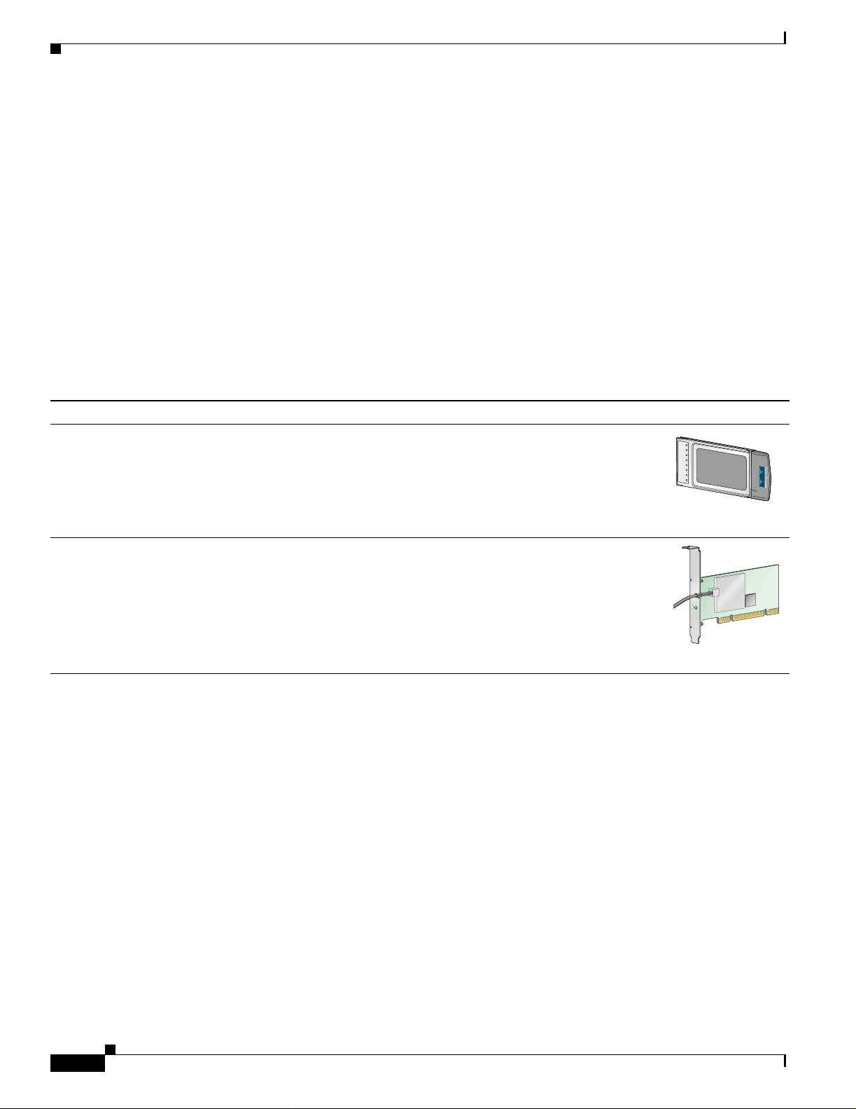
This document covers the two client adapters described in Table 1-1.
Table 1-1 Client Adapter Types
Client Adapter Model Number Description Illustration
PC-Cardbus
card
AIR-CB21AG An IEEE 802 .11a/b/g -comp liant 2.4 - and 5-GH z 54-Mbps cli ent
adapter card radio module with a Cardbus interface that can be
inserted into any device equipped with an ext ernal 32-bit Cardbus
slot. Host devices can include laptops and notebo ok computer s.
95579
PCI card AIR-PI21AG An IEEE 802.11a/b/g -compl iant 2.4- an d 5-GHz 54-M bps clie nt
adapter card rad io module that can be inserte d into any device
equipped with a n emp t y PCI expa ns ion s lo t, su ch as a deskt op
personal computer.
Terminology
The following terms a re u sed thr ough out t his d oc ume nt:
• client adapter—Refers to both types of adapters.
• PC-Cardbus card or PCI card—Refers to a specific adapter.
• workstati on (or station )—Refers to a computing device with an installed client adapter.
• infrastructure device—Refers to a device tha t connects client adapters to a wired LAN, such as an
access point, bridge, or ba se station . Throughou t this doc ument, access point is used to represent
infrastructure d evices in ge nera l.
ACTIVITY
STATUS
95580
1-2
Cisco Aironet 802.11a/b/g Wireless LAN Client Adapters (CB21AG and PI21AG) Installation and Configuration Guide
OL-4211-01
Page 21

Chapter 1 Product Overview
BETA DRAFT - CISCO CONFIDENTIAL
Hardware Components
The client adapte rs have three major ha rdware com po nents : a radio, a ra dio an tenna, and two LED s.
Radio
The client ada pte rs cont ain a d ual- ba nd ra dio th at is b ot h IEE E 80 2.1 1a a nd 802.1 1b/ g c omp lia nt. Th e
radio uses both direct-sequence spread spectrum (DSSS) technology and orthogonal frequency division
multiplexing (OFDM) te chnolo gy f or clie nt a ppl icatio ns in the 2 .4-G Hz Indust ria l Sc ientific Me dic al
(ISM) frequency b and a nd OF DM tec hn ology in th e 5-GH z U nli cen sed N atio nal Infor ma tio n
Infrastructure (UNII) frequenc y bands . It can tr ansmit data at u p to 100 milliw atts (mW) in th e 2.4-GHz
band or up to 40 mW in t he 5- G Hz ban d over a half -du plex ra dio ch anne l op er ati ng at up to 54 Mbps.
The client adapters ope rate wi th other IEEE 802.11 a or 802. 11b/g-c ompliant client devices in ad hoc
mode or with Cisco Airo ne t 340 , 35 0, 110 0, and 1200 Se rie s Acc ess Poi nts a nd ot her I EEE 8 02. 11a or
802.11b/g-compli ant inf rastru cture devices i n infrast ructur e mode. They ar e approved for in door an d
outdoor use in the 2.4-GHz band and for indoor use only in the 5-GHz band except in the United States,
which allows for outdoor use on ch annels 52 thro ugh 64.
Hardware Components
Radio Antenna
LEDs
The type of antenna used depends on you r client adapter:
• PC-Cardbus cards have an integrated, permanently attached dual-band 2.4/5-GHz diversity antenna.
The benefit o f the di versity antenna syst em is impro ved co vera ge. The sys tem works by allo wing the
card to switch and sample between its two antenna ports in order to select the optimum port for
receiving data packets. As a result, the card has a better chance of maintaining the radio frequency
(RF) connection in areas of interference. The antenna is housed within the section of the card that
hangs out of the PC card slot when the card is instal led.
• PCI cards have a 1-dBi dual-band 2.4/5-GHz antenna that is permanently attached by cable. A base
is provided with the antenna to enable it to be mounted to a wall or to sit upright on a desk or other
horizontal surface.
The client adapters have two LEDs that glow or blink to indicate the status of the adapter or to convey
error messages. Refer to Chapte r 10 for an interpretation of the LED codes.
OL-4211-01
Cisco Aironet 802.11a/b/g Wireless LAN Client Adapters (CB21AG and PI21AG) Installation and Configuration Guide
1-3
Page 22

Software Components
BETA DRAFT - CISCO CONFIDENTIAL
Software Components
The client adapters ha ve two major software co mponents: a d riv er and client utilit ies. These co mponents
are installed together b y running a sin gle e xecuta ble Install W i zard f ile that i s av ailable from Cisco.com.
This file can be run on Windows 2000 or XP and can be used only with CB21AG and PI21AG client
adapters.
Note Chapter 3 provides instructions on using the Install Wizard to install these software components.
Driver
The driver provides an inte rfa ce bet we en a co mpu t er ’s operating system and the client adapter, thereby
enabling the operating system and the applications it runs to communicate with the adapter. The driver
must be installed before the adapter can be used.
Client Utilities
Chapter 1 Product Overview
Two client utilities are available for use with the client adapters: Aironet Desktop Utility (ADU) and
Aironet System T ray Utility (ASTU). These utilities ar e optional applications that interact with the client
adapter’s radio to adjust settings and display information.
ADU enables you to crea te configurat ion profiles for your client ad apter and perform user-level
diagnostics. Because ADU performs a variety of functions, it is documented by function throughout this
manual.
ASTU, which is accessible from an icon in the Windows system tray, provides a small subset of the
features available through AD U. Sp ec ifically, it enables you to a cce ss sta tus infor mat ion ab out you r
client adapter and perform basic tasks. Chapter 8 pro vides detailed informati on and instructions on using
ASTU.
Note If your computer is runni ng Windows XP, you can configure your cli ent adapt er throu gh the Windows
operating system instead of through ADU. Refer to Appendix E for information. However, ADU is
recommended f or configu ring t he c lie nt ad ap ter.
1-4
Cisco Aironet 802.11a/b/g Wireless LAN Client Adapters (CB21AG and PI21AG) Installation and Configuration Guide
OL-4211-01
Page 23
Chapter 1 Product Overview
Network Configurations Using Client Adapters
BETA DRAFT - CISCO CONFIDENTIAL
Network Configurations Using Client Adap ters
Client adapters can be used in a variety of network configurations. In some configurations, access points
provide connections to your network or act as repeaters to increase wireless communication range. The
maximum communicati on range i s based on how you configure your wi reless net work.
This section describes and illustrates the two most common network configurations:
• Ad hoc wireless local area network (LAN)
• Wireless infrastructure with workstations accessing a wired LAN
For examples of more complex network configurations involving client adapters and access points, refer
to the documentation fo r your access poi nt.
Note Refer to Chapter 5 for information on setting the client adapter’s network type.
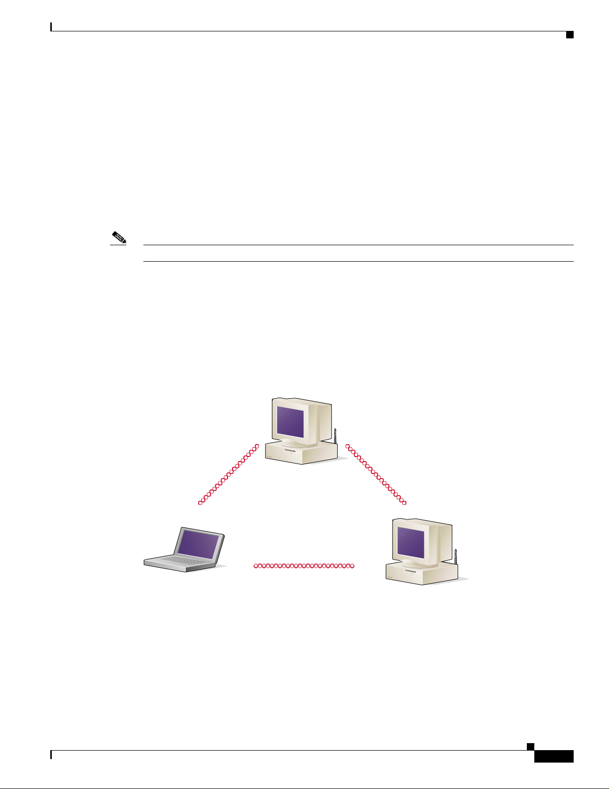
Ad Hoc Wireless LAN
An ad hoc (or peer-to-pe er) wireless LAN (see Figure 1-1) is the simplest wireless LAN configuration.
In a wireless LAN using an ad hoc network configuration, all devices equipped with a client adapter can
be linked together an d c om mun icat e dire ct ly w ith ea ch ot her. The use of an in frast ru ctu re device, su ch
as an access point , i s not requi red.
Figure 1-1 Ad Hoc Wireless LAN
47520
OL-4211-01
Cisco Aironet 802.11a/b/g Wireless LAN Client Adapters (CB21AG and PI21AG) Installation and Configuration Guide
1-5
Page 24
Chapter 1 Product Overview
Network Configurations Using Client Adapters
BETA DRAFT - CISCO CONFIDENTIAL
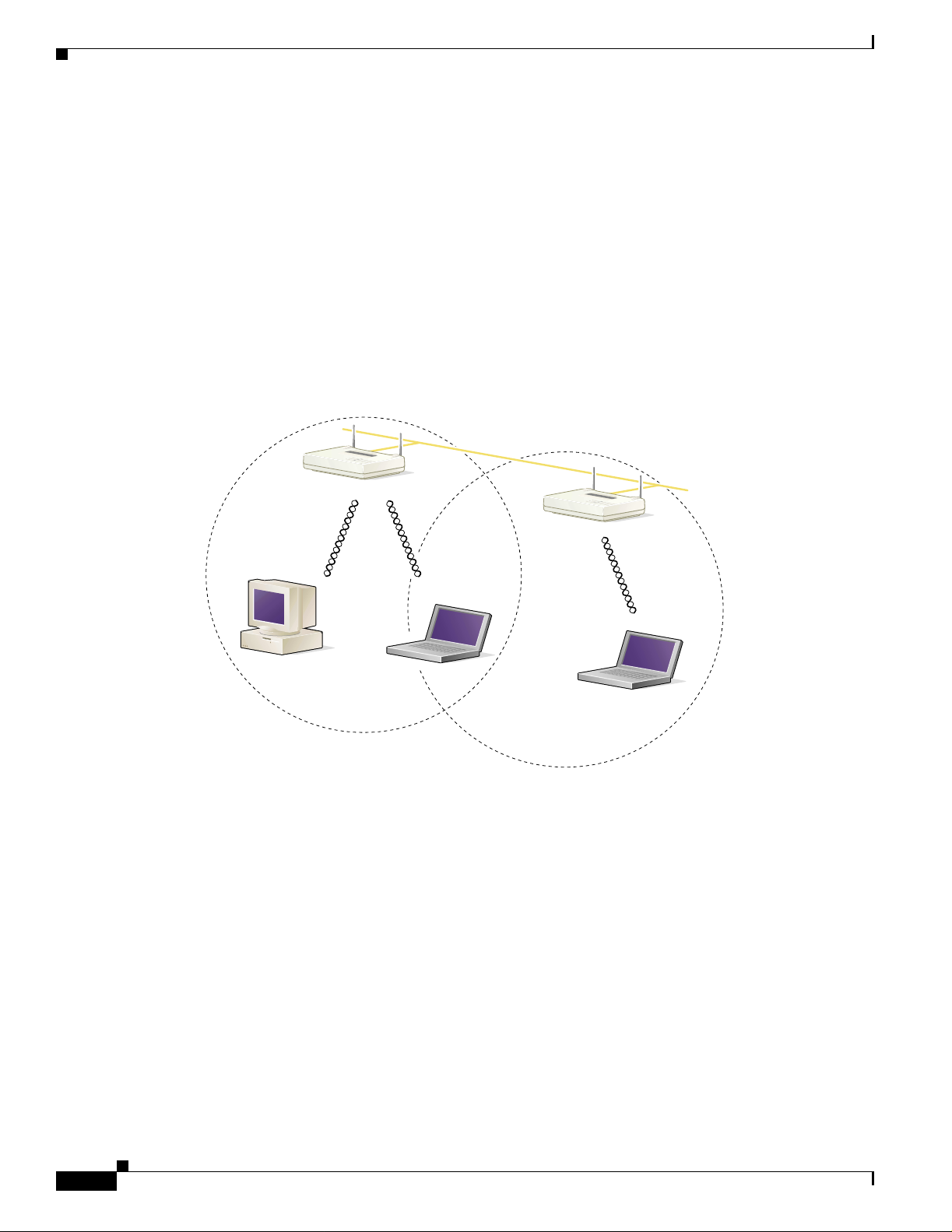
Wireless Infrastructure with Workstations Accessing a Wired LAN
A microcellular network ca n be create d by placing two or mo re access po ints on a LAN . Figure 1-2
shows a microcellular networ k with workstations accessing a wired LAN through several access points.
This configuration is useful with portable or mobile stations because it allows them to be directly
connected to the wired network even while moving from one microcell domain to another. This process
is transparent, and the connection to the f ile serv er or host is maintained witho ut disruption . The mobile
station stays connected to an access point as long as it can. However, once the transfer of data packets
needs to be retried or beacon s are missed, the stati on automatically sear ches for and associates to another
access point. This process is referred to as seamless roaming.
Figure 1-2 Wireless Infrastructure with Workstations Accessing a Wired LAN
Access Point
(Root Unit)
Wired LAN
Access Point
(Root Unit)
1-6
5835
Cisco Aironet 802.11a/b/g Wireless LAN Client Adapters (CB21AG and PI21AG) Installation and Configuration Guide
OL-4211-01
Page 25

BETA DRAFT - CISCO CONFIDENTIAL
CHAPTER
Preparing for Installation
This chapter provides information that you need to know before installing a client adapter.
The following topics are covered in this chapter:
• Safety information, page 2-2
• Unpacking the Clie nt A dapt er, page 2-3
• System Requirements, page 2-4
• Site Requirements, page 2-5
2
OL-4211-01
Cisco Aironet 802.11a/b/g Wireless LAN Client Adapters (CB21AG and PI21AG) Installation and Configuration Guide
2-1
Page 26

Safety information
BETA DRAFT - CISCO CONFIDENTIAL
Safety information
Follow the guidelines in this section to ensure proper operation and safe use of the client adapter.
FCC Safety Compliance Statement
The FCC, with its action in ET Doc ket 96-8, has adop ted a safe ty standard for human exposur e to RF
electromagnetic energy emitted by FCC-certified equipment. When used with approved Cisco Aironet
antennas, Cisco Aironet products meet the uncontrolled environmental limits found in OET-65 and ANSI
C95.1, 1991. Proper operation of this radio device according to the instructions in this publication will
result in user exposure substantially below the FCC recommended limits.
Safety Guidelines
• Do not touch or move the antenna while the unit is transmitting or receiving.
• Do not hold any component containing a radio such that the antenna is very close to or touching any
exposed parts of the body, especially the face or eyes, while transmitting.
• Do not operate the radio or attempt to transmit data unless the antenna is connected; otherwise, the
radio may be damaged.
Chapter 2 Preparing for In stallation
• High-gain, wall-mount, or m ast-mou nt ant enna s ar e desi gned to b e pro fessiona ll y in stall ed a nd
should be located at a minimum distance of 12 inches (30 cm) or more from the body of all persons.
Please contact your professional installer, VAR, or antenna manufacturer for proper installation
requirements.
• Use in specific environme nts :
–
The use of wireless devices in hazardous locations is limited to the constraints posed by the
safety directors of su ch e nvironments.
–
The use of wir eless d evices on airpl ane s is governed by the Fede ra l Aviation Administrat ion
(FAA).
–
The use of wireless devices in hospitals is restricted to the limits set forth by each hospital.
2-2
Cisco Aironet 802.11a/b/g Wireless LAN Client Adapters (CB21AG and PI21AG) Installation and Configuration Guide
OL-4211-01
Page 27

Chapter 2 Preparing for Installation
Warnings
Observe the following warnings when operating the client adapter:
Unpacking the Client Adapter
BETA DRAFT - CISCO CONFIDENTIAL
Warning
Warning
Warning
Do not operate your wireless network device near unshielded blasting caps or in an explosive
environment unless the device has been modified to be especially qualified for such use.
In order to comply with FCC radio frequency (RF) exposure limits, dipole antennas should be located
at a minimum of 7.9 inches (20 cm) or more from the body of all persons.
This device has been tested and complies with FCC RF Exposure (SAR) limits in typical laptop
computer configurations and this device can be used in desktop or laptop computers with side
mounted PC Card slots that can provide at least 0.394 in (1 cm) separation distance from the antenna
to the body of the user or a nearby person. Thin laptop computers may need special attention to
maintain antenna spacing while operating. This device cannot be used with handheld PDAs (personal
digital assistants). Use in other configurations may not ensure compliance with FCC RF exposure
guidelines. This device and its antenna must not be co-located or operated in conjunction with any
other antenna or transmitter.
Translated versions of the se sa fety warn ings are pr ovided in Appendix B.
Unpacking the Client Adapter
Follow these steps to unpack the client adapter:
Step 1 Open the shipping container and carefully remove the contents.
Step 2 Return all packing material s to the sh ipping c onta ine r and save it.
Step 3 Ensure that all item s listed in the “Pack age Conte nts” section belo w ar e includ ed in the shi pment. Ch eck
each item for damage.
Note If any item is damag ed or m issin g, no tif y your a utho riz ed Cisc o sal es r epre se ntative.
Package Contents
Each client adapter is shipped with the following items:
• 1-dBi antenna permanent ly atta ched by cable, antenna base, low-profile brac ket, two mounting
screws, and two plastic wall anchors (PCI cards only)
• Quick Start Guide: Cisco Aironet 802.11a/b/g Wir eless LAN Client Adapters (CB21AG and PI21AG)
• Cisco Aironet 802.1 1a/b /g Wireless Adapte rs (CB21AG and PI21 AG) CD
• Cisco product registration card
Cisco Aironet 802.11a/b/g Wireless LAN Client Adapters (CB21AG and PI21AG) Installation and Configuration Guide
OL-4211-01
2-3
Page 28

System Requirements
BETA DRAFT - CISCO CONFIDENTIAL
System Requirements
In addition to the items shipped with the client adapter, you also need the following items in order to
install and use the adapter:
• One of the following computing devices runni ng Windows 2000 or XP:
–
Laptop, notebook, or portable or handheld device equipped with a 32-bit Cardbus slot
–
Desktop personal compu ter equipp ed wit h an empty PCI expansion sl ot
Note Cisco recommends a 300-MHz processor or greater.
• Service Pack 1 for Windows XP (recommended)
• 20 MB of free hard disk space (minimum)
• 128 MB of RAM or g reat er (rec om mende d)
• The appropriate t ools for rem oving your comp uter’s cover and expansio n sl ot dus t cover and fo r
mounting the antenna base (fo r PCI card s)
Chapter 2 Preparing for In stallation
• The following information from your system administrator:
–
The logical name for you r workstat ion (als o referr ed to as client name)
–
The protocols n ece ssar y to bin d t o the cl ien t ad ap t er
–
The case-sensitive service set identifier (SSID) for your RF network
–
If your computer is not co nnected t o a DHCP server, the IP address, subnet mask , and defaul t
gateway address of your c om pute r
–
The wired equivalent privacy (WEP) keys of the access points with which your client adapter
will communicate, if your wireless network uses static WEP for security
–
The username and password for your network ac count
2-4
Cisco Aironet 802.11a/b/g Wireless LAN Client Adapters (CB21AG and PI21AG) Installation and Configuration Guide
OL-4211-01
Page 29

Chapter 2 Preparing for Installation
BETA DRAFT - CISCO CONFIDENTIAL
Site Requirements
This section discusses the site re quiremen ts for both infr astruc ture and cl ient devices.
For Infrastructure Devices
Because of differen ces i n comp one nt co nfigurat ion, p lac em ent , an d p hysi cal environmen t, every
network application is a unique installation. Therefore, before you install any wireless infrastructure
devices (such as access points, bridges, and base stations, which connect your client adapters to a wired
LAN), a site survey must be performe d to determi ne the opti mum pla cement of t hese devices to
maximize range, coverage, an d network pe rform ance.
Note Infrastructure devices are installed and initially configured prior to client devices.
For Client Devices
Site Requirements
Because the client adapter is a radio device, it is susceptible to RF obstructi ons and common sources of
interference that can reduce throughput and range. Follow these guidelines to ensure the best possible
performance:
• Install the client adapter in an area where large steel structures such as shelving units, bookcases,
and filing cabinets will not obstruct radio signals to and from the client adapter.
• Install the client adapter away from microwave ovens. Microwave ovens operate on the same
frequency as the client adapter and can cause signal interference.
OL-4211-01
Cisco Aironet 802.11a/b/g Wireless LAN Client Adapters (CB21AG and PI21AG) Installation and Configuration Guide
2-5
Page 30

Site Requirements
Chapter 2 Preparing for In stallation
BETA DRAFT - CISCO CONFIDENTIAL
2-6
Cisco Aironet 802.11a/b/g Wireless LAN Client Adapters (CB21AG and PI21AG) Installation and Configuration Guide
OL-4211-01
Page 31

BETA DRAFT - CISCO CONFIDENTIAL
CHAPTER
Installing the Client Adapter
This chapter provides instructions for installing the client adapter.
The following topics are covered in this chapter:
• Inserting a Client Adap ter, page 3-2
• Installing the Client Ada pter Softwa re, page 3-8
• Verifying Installat ion, page 3-18
3
OL-4211-01
Cisco Aironet 802.11a/b/g Wireless LAN Client Adapters (CB21AG and PI21AG) Installation and Configuration Guide
3-1
Page 32

Inserting a Client Adapter
BETA DRAFT - CISCO CONFIDENTIAL
Inserting a Client Adapter
This section provides instructions for inserting a PC-Cardbus card or PCI card into your computer.
Caution These procedures and the phy sical conn ec tions th ey descri be a pp ly g en erall y t o conventional Car dbus
slots and PCI expansion slots. I n ca ses of c ustom o r nonconventional eq uipm ent, b e ale rt to po ssi ble
differences in Cardbus slot and PCI expansion slot configura tions.
Inserting a PC-Cardbus Card
Step 1 Before you begin, examine the card. One end has a dua l-row, 68-pin connector. The card is keyed so it
can be inserted only on e way in to the C ardbus slo t.
Note The Cardbus slot is on the left or right side of the com puter, depending on the mo del.
Chapter 3 Installing the Client Adapter
Step 2 Turn on your computer and let the operating system boot up completely.
Step 3 Hold the card with the Cisco logo facing up and insert it into t he Cardbus slot, applyi ng just e nough
pressure to make s ure it is fu lly se ate d (see Fi gure 3-1).
Caution Do not force the card into your computer’s Cardbus slot. Forcing it will damage both the card and the
slot. If the card does not insert easily, remove the card and reinsert it.
Figure 3-1 Inserting a PC-Cardbus Card into a Computer
Note The profiles for PC-Cardbus cards are tied to the slot in which the card is inserted. Therefore,
you must always insert your PC-Cardbus card into the same slot or create profiles for both slots.
3-2
Step 4 When the Found New Hardware Wizard screen appears, click Cancel.
Step 5 Go to the “Installing the Client Adapter Software” sect ion on page 3-8.
Cisco Aironet 802.11a/b/g Wireless LAN Client Adapters (CB21AG and PI21AG) Installation and Configuration Guide
OL-4211-01
Page 33

Chapter 3 Ins ta ll ing the Client Adapter
BETA DRAFT - CISCO CONFIDENTIAL
Inserting a PCI Card
You must perform the fol lowing procedure s in the order liste d below to insert a PCI card:
• Change the bracket (if requi red), se e below
• Insert the card, page 3-4
• Assemble the antenna, page 3-5
• Mount the antenna, page 3-6
Changing the Bracket
The PCI card is shipped with a full-profile bracket attached. If the PC into which you are inserting the
PCI card requires the card to use a low-profile bracket, follow the steps below to change brackets.
Step 1 Unscrew the two screws that attach the bracket to the card. See Figure 3-2.
Figure 3-2 Changing the PCI Card Bracket
Inserting a Client Adapter
1
ACTIVITY
STATUS
1
1
Step 2
Caution Do not pull on the antenna cable or detach it from the PCI card. The antenna is meant to be permanently
Slide the bracket away from the card; then tilt the bracket to free the antenna cable.
Bracket screws
95581
attached to the card.
Step 3 Hold the low-profile bracket to the card so that the LEDs slip through their corresponding holes on the
bracket.
OL-4211-01
Step 4 Insert the screws that you re moved in Step 1 into the holes on the popu late d side of the ca rd ne ar the
bracket (see Figure 3-2) and tighten.
Cisco Aironet 802.11a/b/g Wireless LAN Client Adapters (CB21AG and PI21AG) Installation and Configuration Guide
3-3
Page 34

Inserting a Client Adapter
Inserting the Card
Step 1 Turn off the PC an d al l i ts c om pon en ts.
Step 2 Remove the computer c over.
Step 3 Remove the screw from the top of the C PU back p an el a bove an e mp ty PCI expa nsion sl ot. Thi s s cr ew
Caution Static electricity can da mage your PC I ca rd. B ef ore re moving the ca rd f rom t he a nt i-s tat ic pack ag ing,
Step 4 Locate an empty PCI expans ion s lo t in side y our c omput er.
Chapter 3 Installing the Client Adapter
BETA DRAFT - CISCO CONFIDENTIAL
Follow the steps below to insert a PCI card into your PC.
Note On most Pentium PCs, PCI expa nsion slot s are w hit e. Refe r to you r PC doc um entat ion f or sl ot
identification.
holds the metal bracket on the back panel.
discharge static by touch ing a met al p art of a g rounde d PC.
Step 5 Slip your card’s antenna through the opening near the empt y expans ion slot so that it i s loca ted ou tsid e
of the computer. See Figure 3-3.
Figure 3-3 Inserting a PCI Card into a PC
1
ACTIVITY
2
1
2
3
Antenna cabl e
LEDs
Card edge conn ector
STATUS
3
ACTIVITY
STATUS
95582
3-4
Step 6
Tilt the card to all ow the LEDs to slip through the open ing in the CPU back panel. See th e enlar ged vie w
in Figure 3-3.
Cisco Aironet 802.11a/b/g Wireless LAN Client Adapters (CB21AG and PI21AG) Installation and Configuration Guide
OL-4211-01
Page 35

Chapter 3 Ins ta ll ing the Client Adapter
BETA DRAFT - CISCO CONFIDENTIAL
Step 7 Press the card into the empty slot until its connector is firmly seated.
Caution Do not force the card into the expansion slot as this could damage both the card and the slot. If the card
does not insert easily, remove it and reinsert it.
Step 8 Reinstall the screw on the CPU back panel and replace the comp uter cover.
Assembling the Antenna
Follow the steps below to assemble the PCI card’s antenna.
Step 1 Slide the antenna through the opening in the bottom of the antenna base.
Step 2 Position the antenna so its notches are facing the Cisco label on the front of the base. See Figure 3 -4.
Figure 3-4 Inserting the Antenna into Its Base
Inserting a Client Adapter
OL-4211-01
1
2
3
95584
1
2
3
Cisco Aironet 802.11a/b/g Wireless LAN Client Adapters (CB21AG and PI21AG) Installation and Configuration Guide
Antenna
Notch
Antenna base
3-5
Page 36

Inserting a Client Adapter
Step 3 Press the antenna cable i n to t he r e cepta cle o n the top of the ba se a s sh own in Figu re 3- 4.
Step 4 Press the antenna straight down into the receptacle until it clicks into place.
Mounting the Antenna
Because the PCI card is a radio device, it is susceptib le to RF obstr uctions an d commo n sources of
interference that can reduce throughput and range. Follow these guidelines to ensure the best possible
performance:
• Install the PCI card’s antenna in an area where large steel structures such as shelving units,
• Install the ant enna away from mi crowave ovens and 2.4-G Hz co rdle ss p hones. T hes e produc ts can
Follow the step s be low to position the PCI card’s antenna on a flat horizontal surface or to mount it to a
wall.
Chapter 3 Installing the Client Adapter
BETA DRAFT - CISCO CONFIDENTIAL
bookcases, and filing cabinets will not obst ruct ra dio signals bei ng transmi tted or received.
cause signal interference because they operate in the same frequency range as the PCI card when
used in 2.4-GHz mod e.
Step 1 Perform one of the following:
• If you want to use the antenna on a flat horizontal surface, position the antenna so it is pointing
straight up. Then go to Step 7.
• If you want to moun t t he a nte nna to a wa ll, go to Step 2.
Step 2 Drill two holes in the wall that are 1.09 inches apart. Figure 3-5 shows the distance between the
mounting holes on the botto m of the anten na base.
Figure 3-5 Bottom of Antenna Base
1.09 inches
3-6
95597
Cisco Aironet 802.11a/b/g Wireless LAN Client Adapters (CB21AG and PI21AG) Installation and Configuration Guide
OL-4211-01
Page 37

Chapter 3 Ins ta ll ing the Client Adapter
BETA DRAFT - CISCO CONFIDENTIAL
Step 3 Tap the two supplied wall anchors into the holes.
Step 4 Drive the two supplied screws into the wall anchors, leaving a small gap between the screw head and the
anchor.
Step 5 Position the mounti ng h o les on th e botto m o f t he an ten na ba se over the screws (see Figure 3-6) and pull
down to lock in place.
Figure 3-6 Mounting the Antenna
Inserting a Client Adapter
Step 6
95595
The antenna rotates 90 degrees from its base. F or optimal rece ption, position the antenna so it is poin ting
straight up (see Fi gure 3-7).
Figure 3 -7 Rotating the Antenna
OL-4211-01
95596
Cisco Aironet 802.11a/b/g Wireless LAN Client Adapters (CB21AG and PI21AG) Installation and Configuration Guide
3-7
Page 38

Installing the Client Adapter Software
BETA DRAFT - CISCO CONFIDENTIAL
Step 7 Boot up your PC.
Step 8 When the Found New Hardware Wizard screen appears, click Cancel.
Step 9 Go to the “Installing the Client Adapter Software” section below.
Installing the Client Adapter Software
This section enables you to in stall Cisco Aironet CB2 1A G o r PI21AG client adapter drive rs and ut ilities
from a single executable file named Win-Client-802.11a -b-g-Ins-Wizard-vx.exe, where x re prese nts the
version number. Follow the steps below to install these client adapter software components on a
computer runn ing Windows 2000 o r XP.
Caution Cisco Aironet CB21AG and PI21AG client adapter software is incompatible with other Ci sco Airone t
client adapter software. Remove or disable any installed Cisco Aironet client adapters before you install
or use a CB21AG or PI21AG adapter and do not open the Aironet Client Utility (ACU). Refer to the
“Disabling a Cisco Airone t Client Adapt er” section on page 10-7 for instructions on disabling a cli ent
adapter.
Chapter 3 Installing the Client Adapter
Caution Do not eject your client adapter at any time dur ing th e insta lla tion pr oce ss, inc lud ing dur in g the re bo ot.
Note This procedure is mea nt t o be u sed th e first tim e t he Ci sco A ironet C B21AG or PI21AG client ad ap ter
software is installed on your computer. If this software is already installed on your computer, follow the
instructions in Chapter 9 to upgrade or uninstall the client ad apter software.
Note Only one client adapter can be installed and used at a time. The software does not support the use of
multiple cards.
Step 1 Use your computer’s web browser to access the following URL:
http://www.cisco.com/public/sw-center/sw-wireless.shtml
Step 2 Select Option #2: Aironet Wireless Soft ware Display Tables.
Note You can download software from the Software Selector tool instead of the display tables. To do
so, select Option #1: Aironet Wireless Sof tware Sele ctor, follow the instructions on the
screen, and g o to Step 6.
Step 3 Select Cisco Aironet Wireless LAN Client Adapters.
3-8
Step 4 Under Aironet Client Ad ap ter In stall ation Wizard (For Windows), select 802.1 1a/b/g (C B21AG,
PI21AG).
Step 5 Select the Install Wizard file with the greatest version number.
Step 6 Read and accept the terms and conditions of the Software License Agreement.
Cisco Aironet 802.11a/b/g Wireless LAN Client Adapters (CB21AG and PI21AG) Installation and Configuration Guide
OL-4211-01
Page 39

Chapter 3 Ins ta ll ing the Client Adapter
BETA DRAFT - CISCO CONFIDENTIAL
Step 7 Select the file again to download it.
Step 8 Save the file to your computer’s hard drive.
Step 9 Use Windows Explor er to find the file.
Step 10 Double-click the file. The “Starting InstallShield Wizard” message appea rs followed by the Preparing
Setup screen (see Figure 3-8) and the Cisco Aironet Installation Program screen (see Figure 3-9).
Figure 3-8 Preparing Setup Screen
Installing the Client Adapter Software
OL-4211-01
Cisco Aironet 802.11a/b/g Wireless LAN Client Adapters (CB21AG and PI21AG) Installation and Configuration Guide
3-9
Page 40

Installing the Client Adapter Software
BETA DRAFT - CISCO CONFIDENTIAL
Figure 3-9 Cisco Aironet Installation Program Screen
Chapter 3 Installing the Client Adapter
Step 11 Click Next. The Setup Type screen appears ( see Figure 3-10).
3-10
Cisco Aironet 802.11a/b/g Wireless LAN Client Adapters (CB21AG and PI21AG) Installation and Configuration Guide
OL-4211-01
Page 41

Chapter 3 Ins ta ll ing the Client Adapter
BETA DRAFT - CISCO CONFIDENTIAL
Figure 3-10 Setup Ty pe Screen
Installing the Client Adapter Software
Step 12 Select one of the following options:
Note To ens ure compat ibility am ong softwa re compone nts, Cisco re commen ds that you install the
client utilities and driver.
• Install Client Utilities and Driver (recommended)—Installs the client adapter driver and client
utilities.
• Install Driver Only—Installs only the client adapter driver. If you select this option, go to Step 24.
• Make Driver Installation Diskette(s)—Enables you to create driver installation diskettes.
Step 13 Click Next.
Step 14 If a message ap pea r s ind ica tin g th at y ou a re re qu ire d to re sta rt y our com put er at th e en d of the
installation process, click Yes.
Note If you click No, you are asked to confirm your decision. If you proceed, the installation process
terminates.
The Choose Destination Location screen a ppears (see Fi gure 3-11).
OL-4211-01
Cisco Aironet 802.11a/b/g Wireless LAN Client Adapters (CB21AG and PI21AG) Installation and Configuration Guide
3-11
Page 42

Installing the Client Adapter Software
BETA DRAFT - CISCO CONFIDENTIAL
Figure 3-11 Choose Destination Location Screen
Chapter 3 Installing the Client Adapter
Step 15 Perform one of the following:
• If you selected the first option in Step 12, click Next to install the client utility files in the
C:\Program Files\Cisco Aironet dir ectory.
Note If you want to install the client utilities in a different directory, click Browse, select a
different directory, click OK, and click Next.
• If you selected the Make Driver Installation Diskette(s) option in Step 12, insert a flop py disk i n to
your computer and clic k Next to copy the driver to the diskette. Go to Step 24.
Note If you want to copy the driver to a different drive or directory, click Browse, select a new
location, click OK, and click Next.
Step 16 The Selec t Progra m Folde r scree n appe ars (s ee Figure 3-12).
3-12
Cisco Aironet 802.11a/b/g Wireless LAN Client Adapters (CB21AG and PI21AG) Installation and Configuration Guide
OL-4211-01
Page 43

Chapter 3 Ins ta ll ing the Client Adapter
BETA DRAFT - CISCO CONFIDENTIAL
Figure 3-12 Select Program Folder Screen
Installing the Client Adapter Software
Step 17 Click Next to add program ic on s to the Cisco Air onet prog ra m folder.
Note If you want to specify a different program folder, select a folder from the Existing Folders list
or type a new folder name in the Prog ram Folder field and click Next.
Step 18 If your computer is running Windows 2000, go to Step 24. If your computer is running Windows XP , the
IMPORTANT: Please Read! screen appears (see Figure 3- 13).
OL-4211-01
Cisco Aironet 802.11a/b/g Wireless LAN Client Adapters (CB21AG and PI21AG) Installation and Configuration Guide
3-13
Page 44

Installing the Client Adapter Software
BETA DRAFT - CISCO CONFIDENTIAL
Figure 3-13 IMPORTANT: Please Read! Screen
Chapter 3 Installing the Client Adapter
Step 19 Read the information displayed and click Next. The Choose Configuration Tool screen appears (see
Figure 3-14).
3-14
Cisco Aironet 802.11a/b/g Wireless LAN Client Adapters (CB21AG and PI21AG) Installation and Configuration Guide
OL-4211-01
Page 45

Chapter 3 Ins ta ll ing the Client Adapter
BETA DRAFT - CISCO CONFIDENTIAL
Figure 3-14 Choose Configuration Tool Screen
Installing the Client Adapter Software
Step 20 Select one of the following options:
• Cisco Aironet Desktop Utility (ADU)—Enable s you to configure yo ur c lient ada pte r usi ng AD U.
• Microsoft Wireless Configuration Manager—Enables you to configure your client adapter using
the Microsoft Wireless Configuration Manager in Windows XP.
To help yo u wi th you r d ecisi on, Table 3-1 compares the Windows XP and ADU cli ent adap ter feat ures.
Table 3-1 Comparison of Windows XP and ADU Client Adapter Features
Feature Windows XP ADU
Configuration parameters Limited Extensive
Capabilities
Create profiles No Yes
Turn radio on or off No Yes
Security
Static WEP Yes Yes
LEAP authentication with dynamic
WEP
EAP-TLS or PEAP authentication Yes Yes
No Yes
OL-4211-01
Cisco Aironet 802.11a/b/g Wireless LAN Client Adapters (CB21AG and PI21AG) Installation and Configuration Guide
3-15
Page 46

Installing the Client Adapter Software
BETA DRAFT - CISCO CONFIDENTIAL
Table 3-1 Comparison of Windows XP and ADU Client Adapter Features (continued)
Feature Windows XP ADU
Diagnostics
Status screen Limited Extensive
Statistics screen (tr ans m it & re ce ive) No Yes
Note If you select Cisco Aironet Desktop Utility (ADU), the Microsoft Wireless Configuration
Manager is disabled. If you ever manually ena ble it, you a re prompt ed to disabl e it whenever
ADU is activated.
Step 21 Click Next.
Step 22 If you selected Cisco Aironet Desktop Utility (ADU) in Step 20, go to Step 24. If you selected Microsoft
Wireless Configuration Manager, the Enable Tray Icon screen appears (see Figure 3-15).
Figure 3-15 Enable Tray Icon Screen
Chapter 3 Installing the Client Adapter
3-16
Step 23 Check the Enable Cisco Aironet System Tray Utility (ASTU) check box if you want to be able to use
ASTU even though you have chosen to configure your client ada pter throug h Windows instead of ADU.
Step 24 When prompted to insert your client adapter, click OK. The Setup Status screen appears (see
Figure 3-16).
Cisco Aironet 802.11a/b/g Wireless LAN Client Adapters (CB21AG and PI21AG) Installation and Configuration Guide
OL-4211-01
Page 47

Chapter 3 Ins ta ll ing the Client Adapter
BETA DRAFT - CISCO CONFIDENTIAL
Figure 3-16 Setup Status Screen
Installing the Client Adapter Software
The installation pro cess begins, an d you are notified as each soft ware compone nt is insta lled.
Note This process may take several minutes.
Step 25 When a message ap pe ar s indic ati ng th at yo ur c omput er ne e ds to be rebo oted , c lick OK and a llow your
computer to re star t .
Note This process may take several minutes.
Step 26 After your computer reboots, the Windows Found New Hardware Wizard appears. Click Next, allow the
wizard to install the software for the client adapter, and click Finish.
OL-4211-01
Cisco Aironet 802.11a/b/g Wireless LAN Client Adapters (CB21AG and PI21AG) Installation and Configuration Guide
3-17
Page 48

Verifying Installation
Step 27 If your computer is not connected to a DHCP server and you plan to use TCP/IP, follow the steps below
Step 28 If you are prompte d to restart your comp uter, click Yes.
Step 29 Go to the “Verifying Installation” section below to determine if the installation was successful.
Chapter 3 Installing the Client Adapter
BETA DRAFT - CISCO CONFIDENTIAL
for your operating system.
• Windows 2000—Double-click My Computer, Control Panel, and Network and Dial-up
Connections. Right-click Local Area Connection x (where x represent s the numbe r of the
connection). C lick Prop er tie s. In the Comp onents Checke d Are Used by Thi s Connectio n field,
select Internet Protocol (TCP/IP) and click Proper tie s . Click Use the following IP address and
enter the IP address, subnet mask, and de fault gateway address of your co mput er (which c an be
obtained from your sy stem adm ini stra tor). Clic k OK twice.
• Windows XP—Double-click My Computer, Control Panel, and Network Connections.
Right-click Wireless Network Connection x (where x represents the number of the connection).
Click Properties. In the This Connection Uses the Following Items field, select Internet Protoc ol
(TCP/IP) and c lick Prop erti e s. Select Use the following IP address and enter the IP address,
subnet mask, and default gateway address of your c omputer (which can be obtai ned from your
system administrator). Click OK twice.
Verifying Installation
To verify th at you have properly instal led th e clie nt adapte r so ftware, ch eck t he client adap ter’s LEDs.
If the installation was successful, the client adapter’s green LED blin ks.
Note If your installat ion was unsu cce ssful or yo u experienc e d prob lem s d uring o r aft er inst alla tio n, re fer to
Chapter 10 for troubleshooting i nformat ion.
Now that your client adapter is p roperly installed, it is ready to be configured.
• If you are planning to co nfigure you r client adapter through ADU , go to Chapte r 4 to create
configuration profiles.
• If you are planning to configure your client adapter through Windows XP’s Wireless Configuration
Manager, go to Appendix E.
3-18
Cisco Aironet 802.11a/b/g Wireless LAN Client Adapters (CB21AG and PI21AG) Installation and Configuration Guide
OL-4211-01
Page 49

BETA DRAFT - CISCO CONFIDENTIAL
CHAPTER
4
Using the Profile Manager
This chapter explains how to use ADU’s profile manager feature to create and manage profiles for your
client adapter.
The following topics are covered in this chapter:
• Overview of Profile Manager, page 4-2
• Opening Profile Manager, page 4-2
• Creating a New Profile, page 4-4
• Including a Profile i n Au to Profile Se lect ion, p age 4-7
• Selecting the Active Profile, page 4-8
• Modifying a Profile, page 4-9
• Importing and Expo rti ng Profiles, page 4- 10
OL-4211-01
Cisco Aironet 802.11a/b/g Wireless LAN Client Adapters (CB21AG and PI21AG) Installation and Configuration Guide
4-1
Page 50

Overview of Profile Manager
BETA DRAFT - CISCO CONFIDENTIAL
Overview of Profile Manager
ADU’s profile manager feature allows you t o cre ate an d m an age up to 16 profiles (or saved
configurations) fo r your client adapter. These profiles enable you to use your client adapter in different
locations, each of which requires different configuration settings. For example, you may want to set up
profiles for using your client adapter at the office, at home, and in public areas such as airports. Once
the profiles are cr e ated, yo u c an e a sily swi tch b etwee n the m witho ut h aving to r e con figure your c li ent
adapter each time you enter a new location.
Profiles are stored in the registry and are lost if you uninstall the client adapter’s software. To prevent
your profiles from becoming lost, Ci sco recom mends that you back up your pro files using the profile
manager’s import/export feature. See the “Importing and Exporti ng Profiles” section on page 4-10 for
details.
Opening Profile Manager
Step 1 To open ADU ’s profile manager, double-click the Aironet Desktop Utility icon on your desktop.
Step 2 Click the Profile Management tab. The Cisco Aironet Desktop Utility (Profile Management) screen
appears (see Figure 4-1).
Chapter 4 Using the Profile M ana ger
Figure 4-1 Cisco Aironet Desktop Utility (Profile Management) Screen
4-2
Note The profile manage r feature provides you with a default profile that is configured to use default values.
This profile is named Default and appears in the profiles list on the Cisco Aironet Desktop Utility
(Profile Manageme nt) scr een. You can use this profile as is or modify it by follow in g the in str uctio ns i n
the “Modifying a Profile” section on page 4-9.
Cisco Aironet 802.11a/b/g Wireless LAN Client Adapters (CB21AG and PI21AG) Installation and Configuration Guide
OL-4211-01
Page 51

Chapter 4 Us in g the Profile Manager
BETA DRAFT - CISCO CONFIDENTIAL
Table 4-1 provides a description of the status fields on the Cisco Aironet Desktop Utility (Profile
Management) screen.
Table 4-1 Description of Status Fields on Profile Management Screen
Field Description
Network Type The type of networ k that is c onfigured for t he se lec ted p rofile.
Security Mode The type of security that is configured for the selected profile.
Network Name 1
(SSID1)
Network Name 2
(SSID2)
Network Name 3
(SSID3)
Opening Profile Manager
Value: Infrastructure or Ad Hoc
Note Refer to the Network Type parameter in Table 5-3 for instructions on
setting the network typ e.
Value: Disabled, Pre-Shared Keys (Static WEP), Pre-Shared Keys, LEAP,
EAP-TLS, PEAP (EAP-GTC), or PEAP (EAP-MSCHAP V2)
The service set identifie r (SSID) is the wireless netw ork that is conf igured for
the selected profile.
Note Refer to the SSID1 parameter in Table 5-2 for instruc t ions on setting
SSID1.
An optional SSID that is configured for the selected profile. It identifies a
second distinct netw ork and enables the cli ent adapter to roam t o that network
without having to b e re co nfigured .
Note Refer to the SSID2 parameter in Table 5-2 for instruc t ions on setting
SSID2.
An optional SSID that is configured for the selected profile. It identifies a
third distinct network and enables the client adapter to roam to that network
without having to b e re co nfigured .
Note Refer to the SSID3 parameter in Table 5-2 for instruc t ions on setting
SSID3.
OL-4211-01
Profile manager allows you to perform the following tasks rela ted to the ma nagement of profiles:
• Create a new profile, page 4-4
• Include a profile in auto profile selection, p age 4-7
• Select the active profile, page 4-8
• Edit a profile, page 4-9
• Delete a profile, page 4-9
• Import a profile, page 4-1 0
• Export a profile, page 4-11
Follow the instructions on the page indicated for the task you want to perform.
Note If your system administrator used an administrative tool to deactivate certain parameters, these
parameters are grayed out and canno t be selecte d.
Cisco Aironet 802.11a/b/g Wireless LAN Client Adapters (CB21AG and PI21AG) Installation and Configuration Guide
4-3
Page 52

Creating a New Profile
BETA DRAFT - CISCO CONFIDENTIAL
Creating a New Profile
Follow the steps below to create a new profile.
Step 1 Perform one of the following:
• If you want to create a new profile from scratch, click New on the Cisco Aironet Desktop Utility
(Profile Management) screen . Then go to Step 4.
• If you want to find a n available ne twork a nd c reat e a p rofile ba sed o n i t, cl ick Scan on the Cisco
Aironet Desktop Utility (Profile Management) screen. The Available Infrastructure and Ad Hoc
Networks screen appear s (see Figure 4-2).
Figure 4-2 Available Infrastructure and Ad Hoc Networks Screen
Chapter 4 Using the Profile M ana ger
4-4
This screen displays a list of all available networks.
Note The Allow Broadcast SSID to Associate opti on on the ac cess point must be en able d for the
SSID to appear in the list of available networks.
Table 4-2 provides a description of the fields on the Available Infrastructure and Ad Hoc Networks
screen.
Cisco Aironet 802.11a/b/g Wireless LAN Client Adapters (CB21AG and PI21AG) Installation and Configuration Guide
OL-4211-01
Page 53

Chapter 4 Us in g the Profile Manager
BETA DRAFT - CISCO CONFIDENTIAL
Table 4-2 Description of Available Infrastructure and Ad Hoc Networks Screen
Field Description
Network Name (SSID) The service set ide ntifier ( SSID) indicates th e name of an
Key icon SSIDs that are designated with a key icon are being
Signal Strength The signal strength for all re ceived packets. The highe r
Creating a New Profile
available wireless network. The icons to the left of the
SSIDs provide information on network type and link
status.
Icon Description
An available infrastructur e ne twork .
The infrastructur e ne twork to w hich y our
client adapter is currently associated.
An available ad hoc network.
The ad hoc network to which your client
adapter is currently associated.
advertised as secure networks.
the value, the stron ger the si gnal.
Note The color of this parameter’s icon provide s a
visual interpretation of signal strength:
Excellent or Good (g re en ), Fair ( yellow), Poor
(red).
Note The signal strength is displayed either in decib els
(dB) or as a percentage (%), depending on the
value selected for the Signal Strength Display
Units parameter on the Display Settings screen.
See the “Setting Parameters that Affect ADU
Diagnostic Tools” section on page 7-2 for more
information.
Channel The channel that the access point is using for
communications.
Wireless Mode The frequency and rate at which the access point is
configured to transmit and receive packets.
The informati on on t he Available Infrastructure and A d Hoc Ne tworks sc reen i s u pdat ed a t t he ra te
specified by the Refresh Interval parameter on the Display Settings screen. See the “Setting Parameters
that Affect ADU Diagnostic Tools” sect ion on page 7-2 for more information. You can also click the
Refresh button to u pdate the list of available networks.
Step 2 Scroll down to see the full list of available networks.
Step 3 Click on the SSID of the network to which you wa nt your clie nt adapte r to associate and click Activate .
OL-4211-01
Step 4 When the Profile Management (General) screen appears (see Figure 4-3), ent er a name for your new
profile (such as Office, Home, etc.) in the Profile Name field.
Cisco Aironet 802.11a/b/g Wireless LAN Client Adapters (CB21AG and PI21AG) Installation and Configuration Guide
4-5
Page 54

Creating a New Profile
Chapter 4 Using the Profile M ana ger
BETA DRAFT - CISCO CONFIDENTIAL
Figure 4-3 Profile Management (General) Screen
Step 5 Perform one of the following:
• If you want this profile to use the default values, click OK. The profile is added to the profiles list
on the Cisco Aironet Desktop Utility (Profile Management) screen.
Note If you are creating a profile after scanning for an available network, the SSID of the network
appears in th e S SI D1 fiel d .
• If you want to cha ng e any of t h e co nfigur ation pa rame te r s ett ings, fol low the i n struc tions in
Chapter 5. The profile is added to the profiles list on the Cisco Aironet Desktop Utility (Profile
Management) screen.
Note The profiles for PC-Cardbus cards are tied to the slot in which the card is inserted. Therefore, you must
always insert your PC-Cardbus card into the same slot , create profiles for both slots, or expor t the
profiles from one slot an d im por t t hem fo r th e othe r slot.
4-6
Cisco Aironet 802.11a/b/g Wireless LAN Client Adapters (CB21AG and PI21AG) Installation and Configuration Guide
OL-4211-01
Page 55

Chapter 4 Us in g the Profile Manager
BETA DRAFT - CISCO CONFIDENTIAL
Including a Profile in Auto Profile Selection
After you have created profiles for your client adapter, you can choose to include them in the profile
manager’s auto profile selection feature. Then when auto profile selection is enabled, the client adapter
automatically selects a profile from the list of profiles that were included in auto profile selection and
uses it to establish a connection to the network.
Follow the steps belo w to include an y of your prof iles in auto prof ile sele ction and to establish the order
in which the profiles will be selected for use.
Step 1 Open ADU and click the Profile Management tab .
Step 2 Click Order Profiles. The Auto Profile Selection Management screen appears (see Figure 4-4).
Figure 4-4 Auto Profile Selection Management Screen
Including a Profile in Auto Profile Selection
OL-4211-01
Step 3
All the profiles that you crea ted are listed in the Available Prof iles box. Highlight each one th at you want
to include in auto profile selection and click the Add button. The profiles appear in the Auto Selected
Profiles box.
The following rules apply to auto profile selection:
• You must include at least two profiles in the Auto Selected Profiles box.
• The profiles must spec ify an SSID; ot herwis e, they do not appe ar in the Available Profiles
box.
• Profiles cannot specify multiple SSIDs; otherwise, they do not appear in the Available
Profiles box.
Cisco Aironet 802.11a/b/g Wireless LAN Client Adapters (CB21AG and PI21AG) Installation and Configuration Guide
4-7
Page 56

Selecting the Active Profile
Note If you ev er w ant to remo v e a prof ile f rom auto profile selection, highlight the prof ile in the Au to
Step 4 The first profile in the Auto Selec ted Profiles box has t h e hi gh est prior ity whil e t he l ast profile has t he
lowest priority. To change the order (and pri ority) of your auto-selectable profiles, hi ghlight the profile
that you want to move and click Move up or Move down to move the profile up or down, respe ctively.
Step 5 Click OK.
When auto profile selection is enabled (see the “Selecting the Active Profile” section below for
instructions), the client adapter scan s f or an available network. The profile with th e hig hes t priori ty a nd
the same SSID as o ne of the f oun d netwo rks i s the one t hat i s used to conn ec t to t he n etwor k. If the
connection fails, the client adapter tries the n ext highe st priority prof ile that matches the SSID and so o n.
Chapter 4 Using the Profile M ana ger
BETA DRAFT - CISCO CONFIDENTIAL
• Each profile that is included in auto profile selection must have a unique SSID. For example,
if Profile A and Profile B both have “ABCD” as their SSID, only Profile A or Profile B (whichever
one was created first) appears in the Available Profiles box and can be included in auto profile
selection.
Selected Profil es box an d click Remove. The profile is removed from the Auto Selected Profi les
box.
Selecting the Active Profile
Follow the steps below to specify the profile that the client adapter is to use.
Note You can use ASTU instead of ADU’s Profile Manager to select the active profile. Refer to Chapter 8 for
instructions.
Step 1 Open ADU and click the Profile Management tab. The Cisco Aironet Desktop Utility (Profile
Management) screen appears (see Figure 4-1).
Step 2 Perform one of the following:
• Select one profile for the client adapter to use by clicking on that profile in the profiles list.
If the client adapter ca nnot as socia te to an access po int or lo ses ass ociatio n while us ing th e sele cted
profile, th e adapter does no t attempt to asso ciate usin g anoth er prof ile. To associate, you m ust selec t
a different profile or activate auto profile selection.
• Enable auto profile selection by checking the Auto Select Profiles check box.
This option causes the c lient adapter’s driver to automatically select a prof ile from the list of p rofiles
that were set up to be included in auto profile selection.
If the client adapter loses association for more than 10 seconds (or for more than the time specified
by the LEAP authentication timeout value on the LEAP Settings screen if LEAP is enabled), the
driver sw itches automatically to anothe r profile that is incl uded in auto prof ile selection. The adapte r
will not switch prof ile s as long as it remains as socia ted or r easso ciates w ithin 1 0 seco nds (o r within
the time specifi ed by the LEAP a uthentication ti meout valu e). T o force the client adapter to associate
to a different access point, you must unch eck the Auto Select Profiles check box and select a new
profile from the profiles list.
4-8
Cisco Aironet 802.11a/b/g Wireless LAN Client Adapters (CB21AG and PI21AG) Installation and Configuration Guide
OL-4211-01
Page 57

Chapter 4 Us in g the Profile Manager
BETA DRAFT - CISCO CONFIDENTIAL
Note This option is available only if two or more profiles are included in auto profile selection.
Note Login scripts are n ot r elia ble i f you use auto pr ofile sele c tion w it h LEAP. If you LEAP
• Click Scan. The Availabl e Infrast ructu re and Ad Ho c Networks scr een ap pears (s ee Figure 4-2).
Double-click the SSID of a network that is used by one of your profiles and click OK. Go to Step 4 .
Step 3 Click Activate to save your selection.
Step 4 The client adapter starts using a profile based on the option selected above. The active profile is
designated by the following icon in the profiles list:
Modifying a Profile
authenticate and achie v e full netwo rk connecti vity before or at the same time as y ou log into
the computer , the login scrip ts will run. Ho we ver, if you LEAP authenticate and achie v e full
network connectivity after you log into the computer, the login scripts will not run.
Modifying a Profile
This section provides instructions for modifying an existing profile. Follow the steps in the
corresponding sect ion below to edit or del ete a profile.
Editing a Profile
Step 1 Open ADU and click the Profile Management tab. The Cisco Aironet Desktop Utility (Profile
Management) screen appears (see Figure 4-1).
Step 2 In the profiles list, highlight the profile that you want to edit.
Step 3 Click Modify.
Step 4 Follow the instructions in Chapter 5 to change any of the configuration parameters for this profile.
Deleting a Profile
Step 1 Open ADU and click the Profile Management tab. The Cisco Aironet Desktop Utility (Profile
Management) screen appears (see Figure 4-1).
Step 2 In the profiles list, highlight the profile that you want to delete.
OL-4211-01
Step 3 Click Remove. T he pr ofile i s del eted.
Cisco Aironet 802.11a/b/g Wireless LAN Client Adapters (CB21AG and PI21AG) Installation and Configuration Guide
4-9
Page 58

Importing and Exporting Profiles
BETA DRAFT - CISCO CONFIDENTIAL
Importing and Exporting Profiles
This section provide s instruc ti ons for i mpor t ing a nd expo rt ing pro files. You may want to use the
import/export feature for the following reasons:
• To back up profiles before unin stall ing clie nt adapte r software
• To export profiles for a PC-Cardb u s card in one Cardbus sl ot and export them for us e with a second
Cardbus slot
• To set up you r compute r with a profile from anot her comp uter
• To export one o f y our p rofiles a nd use i t to se t up addi tiona l c om puters
Follow the steps in the co rrespo ndi ng se ctio n b elow to i mpor t or expor t pr ofiles.
Importing a Profile
Step 1 If the profile that you want to import is on a floppy disk, insert the disk into your computer’s floppy drive.
Step 2 Open ADU and click the Profile Management tab. The Cisco Aironet Desktop Utility (Profile
Management) screen appears (see Figure 4-1).
Step 3 Click Import. The Import Profile screen appears (see Figure 4- 5).
Chapter 4 Using the Profile M ana ger
Figure 4-5 Import Profile Screen
Step 4
Step 5 Select the profile that you want to import so it appea rs in th e Fil e name box at the bott om of the sc reen .
Step 6 Click Open. The imported profile appears in the profiles list on the Cisco Aironet Desktop Utility
In the Look in dr op-down box , find the di rect o ry whe re t he p rofile is l oca ted.
(Profile Management) scre en .
4-10
Cisco Aironet 802.11a/b/g Wireless LAN Client Adapters (CB21AG and PI21AG) Installation and Configuration Guide
OL-4211-01
Page 59

Chapter 4 Us in g the Profile Manager
BETA DRAFT - CISCO CONFIDENTIAL
Exporting a Profile
Step 1 Insert a blank floppy disk int o your co mpu ter ’s floppy drive, if you wi sh to expo rt a pr ofile to a flo ppy
disk.
Step 2 Open ADU and click the Profile Management tab. The Cisco Aironet Desktop Utility (Profile
Management) screen appears (see Figure 4-1).
Step 3 In the profiles list, select the profile that you want to export.
Step 4 Click Export. The Export Profile screen appears (see Figure 4-6).
Figure 4-6 Export Profile Screen
Importing and Exporting Profiles
OL-4211-01
The profile name a ppear s in t he Fi le name box .
Step 5 Select a directory (for example, your co mputer ’s floppy disk drive or a location on the network) from
the Save in drop-down box.
Note The default location is the Prof iles fold er in the di recto ry wh ere ADU is installed (for e x am ple,
C:\Program Files\Cisco Aironet\Profiles).
Step 6 Click Save. The profile is exported to the specified location.
Step 7 Follow the instructions in the “Importi ng a Profile” section to import the profile on anothe r comp uter.
Cisco Aironet 802.11a/b/g Wireless LAN Client Adapters (CB21AG and PI21AG) Installation and Configuration Guide
4-11
Page 60

Importing and Exporting Profiles
Chapter 4 Using the Profile M ana ger
BETA DRAFT - CISCO CONFIDENTIAL
4-12
Cisco Aironet 802.11a/b/g Wireless LAN Client Adapters (CB21AG and PI21AG) Installation and Configuration Guide
OL-4211-01
Page 61

BETA DRAFT - CISCO CONFIDENTIAL
CHAPTER
5
Configuring the Client Adapter
This chapter expla ins h ow to c hange the co nfigurati on pa ra met ers f or a spe c ific profile. The f ollowing
topics are covered in this chapter:
• Overview, page 5-2
• Setting General Parameters, page 5-3
• Setting Advanced Parameters, page 5-5
• Setting Security Parameters, page 5-10
OL-4211-01
Cisco Aironet 802.11a/b/g Wireless LAN Client Adapters (CB21AG and PI21AG) Installation and Configuration Guide
5-1
Page 62

Overview
Overview
Note If you do not chang e any o f th e configur ation pa r amet ers, the d efaul t values a re us ed .
Note If you are plan ni ng to set pa rame ter s o n m or e th an o ne of t he Pr ofile Mana geme nt scr een s, wa it un t il
Chapter 5 Configuring the Client Adapter
BETA DRAFT - CISCO CONFIDENTIAL
When you choose t o crea te a new p rofile or mo dify an existing pr ofile on th e Ci sco A iro ne t D eskt op
Utility (Profile Man ag emen t) scree n, the Profile Management screens appear. These screens enable you
to set the configuration parameters for that profile.
you are finished with all of the screens before clicking OK . When you click OK, you are returned to the
Cisco Aironet Desktop Utility (Profile Management) screen.
Each of the Profile Management screens (listed below) contains parameters that affect a specific aspect
of the client adapter:
• General—Pr epar es th e clie nt ad apte r for use in a wirel ess netwo rk
• Advanced—Controls how the client adapter operates within an infrastructure or ad hoc network
• Security—Controls how a client adap ter associa tes to an access poin t, authen ticates to the wireles s
network, and encry pt s a nd dec ryp ts da ta
Table 5-1 enables yo u to qu ickly loc ate in struc tions for set ting ea ch Pr ofile Ma nage ment scr een ’s
parameters.
Table 5-1 Locating Configuration Instructions
Parameter Category Page Number
General page 5-3
Advanced page 5-5
Security page 5-10
5-2
Cisco Aironet 802.11a/b/g Wireless LAN Client Adapters (CB21AG and PI21AG) Installation and Configuration Guide
OL-4211-01
Page 63

Chapter 5 Conf igu ri ng the Client Adapter
BETA DRAFT - CISCO CONFIDENTIAL
Setting General Parameters
The Profile Management (General) screen (see Figure 5-1) enables you to set parameters that prepare
the client adapter fo r use in a wirel ess network. This scr een appe ars afte r you click New or Modify on
the Cisco Aironet Desktop Utility (Profile Management) screen.
Figure 5-1 Profile Management (General) Screen
Setting General Parameters
OL-4211-01
Table 5-2 lists and describes the client adapter’s general parameters. Follo w th e in structions in the table
to change any parameters.
Table 5-2 Profile Management General Parameters
Parameter Description
Profile Name The name assigned to the configuration pr ofile.
Range: You can key in up to 32 ASCII characters
Client Name A logical name for your workstat ion. It allows an admi nistrat or to
determine which devices are connected to the access point without
having to memorize every MAC address. This name is included in the
access point’s list of connected devices. The client name is filled in
automatically but can be changed.
Range: You can key in up to 16 ASCII characters
Default: The name of y our c om pute r
Note Each compute r on the network should have a unique clie nt
name.
Cisco Aironet 802.11a/b/g Wireless LAN Client Adapters (CB21AG and PI21AG) Installation and Configuration Guide
5-3
Page 64

Setting General Parameter s
Table 5-2 Profile Management General Parameters (continued)
Parameter Description
SSID1 The service set identifier (SSID) identifies the specific wireless
SSID2 An optional SSID that identifies a second distinct network and enables
Chapter 5 Configuring the Client Adapter
BETA DRAFT - CISCO CONFIDENTIAL
network that you want the client adapter to access.
Range: You ca n key in up to 32 ASC II char act ers (c ase sens itive)
Default: A blank field
Note If you leave this par amete r blank, your client adap ter can
associate to any access point on the network t ha t is co nfigured
to allow broadcast SSIDs. If the access point with whi ch the
client adapter is to communicate is not configured to allow
broadcast SSIDs, the value of this parameter must match the
SSID of the access point. Otherwise, the client adapte r is unable
to access the network.
the client adapter to roam to that network without having to be
reconfigured.
Range: You ca n key in up to 32 ASC II char act ers (c ase sens itive)
Default: A blank field
Note If a profile specifies more than one SSID, it cannot be included
in auto profile selection.
Note This field is un available for any profiles that are i nclude d in
auto profile selection o r configured for use in an ad hoc
network.
SSID3 An optional SSID that id entifies a t hird distinct netwo rk and enables the
client adapter to roam to that network without having to be
reconfigured.
Range: You ca n key in up to 32 ASC II char act ers (c ase sens itive)
Default: A blank field
Note If a profile specifies more than one SSID, it cannot be included
in auto profile selection.
Note This field is un available for any profiles that are i nclude d in
auto profile selection o r configured for use in an ad hoc
network.
Go to the next section to set additional parameters or click OK to save your cha nge s an d r etu rn to t he
Cisco Aironet Desktop Utility (Profile Management) screen.
5-4
Cisco Aironet 802.11a/b/g Wireless LAN Client Adapters (CB21AG and PI21AG) Installation and Configuration Guide
OL-4211-01
Page 65

Chapter 5 Conf igu ri ng the Client Adapter
BETA DRAFT - CISCO CONFIDENTIAL
Setting Advanced Parameters
The Profile Management (Advanced) screen (see Figure 5-2) enables you to set parameters that control
how the client adapter operates within an infrastructure or ad hoc network. To access this screen, select
the Advanced tab from any Profile Management scr een.
Figure 5-2 Profile Management (Advanced) Screen
Setting Advanced Parameters
OL-4211-01
Table 5-3 lists and describes the client adapter’s advanced parameters. Follow the instructions in the
table to change any parameters.
Cisco Aironet 802.11a/b/g Wireless LAN Client Adapters (CB21AG and PI21AG) Installation and Configuration Guide
5-5
Page 66

Setting Advanced Parameter s
Table 5-3 Profile Management Advanced Parameters
Parameter Description
Transmit Power Level Defines the power level at which your client adapter transmits. This
Chapter 5 Configuring the Client Adapter
BETA DRAFT - CISCO CONFIDENTIAL
value must not be higher than that allowed by your country’s regulatory
agency (FCC in the U.S., DOC in Canada, ETSI in Europe, MKK in
Japan, etc.).
Options:Depe nd en t on the r ad io b an d u sed a nd t he power ta ble
programmed into the client adapter; see the table below
Default: The maximum power le vel programmed into the client adapter
and allowed by your co untr y’s regulatory agency
Radio Band Transmit Power Level
802.11b/g 10, 20, 32, 50, 63, or 100 mW
802.11a 10, 13, 20, 25, or 40 m W
Note Reducing the transmit p ower level con s er ves battery power but
decreases radio ra ng e.
5-6
Cisco Aironet 802.11a/b/g Wireless LAN Client Adapters (CB21AG and PI21AG) Installation and Configuration Guide
OL-4211-01
Page 67

Chapter 5 Conf igu ri ng the Client Adapter
BETA DRAFT - CISCO CONFIDENTIAL
Table 5-3 Profile Management Advanced Parameters (continue d)
Parameter Description
Power Save Mode Sets your client adapter to its optimum power consu mption settin g.
Setting Advanced Parameters
Options:CAM (Constantly Awake Mode), Fast PSP (Power Save
Mode), or Max PSP (Max Power Saving)
Default: CAM (Constantly Awake Mode)
Power Save Mode Description
CAM (Constantly Awake
Mode)
Keeps the client adapter powered up
continuously so there is little lag in
message response time.
Consumes the most power but offers the
highest throughput. Is r ecom me nded f or
desktop computers a nd devices t hat use
AC p o we r.
Fast PSP (Power Save
Mode)
Switches between PSP mode and CAM
mode, depending on ne twork tra ffic. This
mode switches to CAM when retrieving a
large number of packets and switches back
to PSP after the packets have been
retrieved.
Is recommended when power consumption
is a concern but you need greater
throughput than tha t all owed by Max PSP.
Max PSP (Max Power
Saving)
Causes the access point to buffer incoming
messages for the client adapter, which
wakes up periodically and polls the access
point to see if any buffered messages are
waiting for it. The adapter can request
each message an d t h en go bac k t o s le ep .
Conserves the most power but offers the
lowest throughput. Is recomm ended for
devices for which power consumption is
the ultimate concern (such as small
battery-powered devices).
Note If you selec t Ad Hoc for N etwork Type, CAM mode is used
automatically.
OL-4211-01
Cisco Aironet 802.11a/b/g Wireless LAN Client Adapters (CB21AG and PI21AG) Installation and Configuration Guide
5-7
Page 68

Setting Advanced Parameter s
Table 5-3 Profile Management Advanced Parameters (continue d)
Parameter Description
Network Type Specifies the type of network in whi ch your clie nt adapte r is installe d.
Chapter 5 Configuring the Client Adapter
BETA DRAFT - CISCO CONFIDENTIAL
Options:Infrastructure or Ad Hoc
Default: Infrastructure
Network Type
Description
Ad Hoc Often referred to as peer to peer. Indicates
that your wirele ss n etwork c on sis ts of a
few wireless devices that ar e not
connected to a wired Eth erne t network
through an access point. For example, an
ad hoc network c ould be set up bet we en
computers in a conference room so users
can share information in a meeting.
Infrastructure Indicates that your wireless network is
connected to a wired Eth erne t network
through an access point.
802.11b Preamb le Det ermi nes wh eth er yo ur c lie nt a dapt er w ill u se bo th sh ort an d lo ng
radio headers or only lo ng radio head ers. Th e adap ter can use short
radio headers only if the access point is also configured to support them
and is using them. If any clients associated to an access point a re u sin g
long headers, then all clients in that cell must also use long headers,
even if both this client and the access point have short radio head ers
enabled.
Short radio headers improve throu ghput per formanc e; long radio
headers ensure compatibility with clients and access points that do not
support short radio headers.
Options:Short & Lo ng or Long Onl y
5-8
Default: Short & Long
Wireless Mode Specifies the frequency and rate a t which your client ad apte r will
transmit or rece ive packets to or fr om acces s poin ts.
Options:5 GH z 54 M bp s, 2.4 GH z 11 M bps, a nd 2 .4 G Hz 54 Mb ps
Default: All options selected
Note When more than one option is selected, the client adapter
attempts to use the wireless modes in this order:
2.4 GHz 54 Mbps, 5 GHz 54 Mbps, 2.4 GHz 11 Mbps.
Note If you select 2.4 GHz 54 Mbps, the client attempts to associate
to access points containing an 802.11b or 802.11g radio. If you
select 2.4 GHz 11 Mbps, the clie nt attempts to associate only to
access points containing an 802.11b radi o.
Note Your client adapter’s wireless mode must match that of the
access points with which it is to communica te. Otherwise, yo ur
client adapter may not be able to associate to them.
Cisco Aironet 802.11a/b/g Wireless LAN Client Adapters (CB21AG and PI21AG) Installation and Configuration Guide
OL-4211-01
Page 69

Chapter 5 Conf igu ri ng the Client Adapter
BETA DRAFT - CISCO CONFIDENTIAL
Table 5-3 Profile Management Advanced Parameters (continue d)
Parameter Description
Wireless Mode When Starting
Ad Hoc Network
Channel Specifies the channel that your client adapter will use for
Setting Advanced Parameters
Specifies the frequency and rat e at which your clie nt adap ter wi ll
transmit or receive packets to or from other cl ients (i n ad hoc mod e).
Options:5 GH z 54 M bp s or 2 .4 G Hz 54/11 M bp s
Default: 5 GHz 54 Mbp s
Note Your client adapter’s wireless mode must match that of the
other clients with which it is to communicate. Otherwise, your
client adapter may not be able to associate to them.
Note The client scans the band(s) specified by the Wireless Mode
parameter before cre at ing a new ad hoc cell base d on the band
specified by the Wireless Mode When Starting Ad Hoc
Network parameter.
communications in a 2. 4-GH z ad hoc netwo rk. The available channe ls
conform to the IE EE 8 02. 11 Stan da rd for y our regulat or y d omai n.
The channel of the c lient adapter m ust be set to match th e chan nel use d
by the other clients in the wireless network. If the client adapter does
not find any other ad ho c cli ent s, thi s p aram e ter spec ifies the c hann el
with which the adapter will start its cell.
Range: Dependen t on regulatory domain
Example: 1 to 11 (241 2 to 24 62 MHz ) in N o rth Amer i ca
Default: Auto (the client automatically determines the channel on
which to start communications)
Note This para met er i s available only whe n 2.4 G Hz 54 /11 Mb ps is
selected for the W ireless Mode When Starting A d Hoc Networ k
parameter. When 5 GHz 54 Mbps is selected, the Channel
parameter is set to Auto automatically.
Note Refer to Appendix D for a list of channel identifiers, channel
center frequencies, and regulatory domains for each channel.
If your client a dapt er is bei ng configure d f or use i n a n i nfra stru ct ure net work a nd yo u want to sp eci fy
up to four access points to which the client adapter should attempt to associate, click Preferred APs.
The Preferred Access Points screen appears (see Figure 5-3).
OL-4211-01
Cisco Aironet 802.11a/b/g Wireless LAN Client Adapters (CB21AG and PI21AG) Installation and Configuration Guide
5-9
Page 70

Setting Security Parameters
Figure 5-3 Preferred Access Points Screen
Chapter 5 Configuring the Client Adapter
BETA DRAFT - CISCO CONFIDENTIAL
Leave the Specified Access Point fields blank or enter the MAC addresses of up to four preferred access
points to which the client adapter can associate; then click OK. If the specified access points are not
found or the cli ent ada pter r oa ms out of ra nge , t he a dapt er may a sso cia te to a no ther ac cess p oint .
Note This paramete r shou ld be use d o nly for a cce ss po ints that ar e in r e peat er mod e. For no rm al
operation, leave these fields bl ank be cause spe cify ing an acc ess p oint slows down the r oa ming
process.
Go to the next section to set additional parameters or click OK to save your cha nge s an d r etu rn to t he
Cisco Aironet Desktop Utility (Profile Management) screen.
Setting Security Parameters
The Profile Management (Security) screen (see Figure 5-4) enables you to set parameters tha t control
how the client adap ter associates to an access point, authenticat es to the wir eless network, and encrypts
and decrypts data. To access this screen, select the Security tab from any Profile Management scree n.
5-10
Cisco Aironet 802.11a/b/g Wireless LAN Client Adapters (CB21AG and PI21AG) Installation and Configuration Guide
OL-4211-01
Page 71

Chapter 5 Conf igu ri ng the Client Adapter
BETA DRAFT - CISCO CONFIDENTIAL
Figure 5-4 Profile Management (Security) Screen
Setting Security Parameters
This screen is different from the other Profile Management screens in that it includes many security
features, each of which involves a number of steps. In addition, the security features themselves are
complex and need to be under stood befo re they are i mpleme nted. Therefor e, this se ction pr ovides an
overview of the security features as well as procedures for using them.
However , before you determine the appropriate security settings for your client adapter, you must decide
how to set the Allow Association to Mixed Cells parameter, which appears at the bottom of the Profile
Management (Secur ity ) s cr ee n and is no t ass o ciated to any of the security features. See the “Setting the
Allow Association to Mixed Cells Parameter” section below.
Setting the Allow Association to Mixed Cells Parameter
The Allow Association to Mixed Cells parameter indicates whether the client adapter can associate to
an access point that allows both WEP and non-WEP associations. Follow the steps below to set this
parameter.
Step 1 Perform one of the following:
• Check the Allow Association to Mixed Cells check box if the access point to which the client
adapter is to associate has WEP set to Op tional and WEP is enabled on th e client adapter . Otherwise,
the client is unable to establish a connection with the access point.
• Uncheck the Allow Association to Mixed Cells check box if the access point to which th e client
adapter is to associate does not have WEP set to Optional. This is the default setting.
OL-4211-01
Cisco Aironet 802.11a/b/g Wireless LAN Client Adapters (CB21AG and PI21AG) Installation and Configuration Guide
5-11
Page 72

Setting Security Parameters
BETA DRAFT - CISCO CONFIDENTIAL
Note For security reasons, Cisco recommends that WEP-enabled and WEP-disabled clients not be
allowed in the same cell because broadcast packets are sent unencrypted, even to clients running
WEP.
Step 2 Perform one of the following:
• If you do not want to change any other paramet ers on the Profile Mana gement (Securi ty) screen,
click OK to save your changes and return to the Cisco Aironet Desktop Utility (Profile
Management) screen.
• If you want to change some of the other par ameters on t he Profile Manageme nt (Secur ity) scr een,
go to the next section.
Overview of Security Featu res
You can protect your data as it is transmitted through your wireless network by encrypting it through the
use of wired equivalent privacy (WEP) encryption keys. With WEP encryption, the transmitting device
encrypts each packet with a WEP key, and the receiving device uses that same key to decrypt each
packet.
Chapter 5 Configuring the Client Adapter
Note Refer to the “Additional WEP Key Security Features” section on page 5-16 for information on three
Static WEP Keys
The WEP keys used to encrypt and decrypt transmitted data can be statically associated with your
adapter or dynamically created as part of the EAP authentica tion process. The informat ion in the “Static
WEP Keys” and “EAP (with Dynamic WEP Keys)” sections below can help you to decide which type
of WEP keys you want to use. Dynamic WEP keys with EAP offer a higher degree of security than static
WEP keys.
WEP keys, whether static or dyna mic , are e ither 40 o r 1 28 bi ts i n leng th. 128-b i t WE P keys offer a
greater level of security than 40-bit WEP keys.
security features that ca n make your WEP keys even more secure.
Each device (or profile) w ith in yo ur wi reless ne twork can be assign ed u p to fo ur stat ic WE P keys. If a
device receives a packet that is not encrypted with the a ppropr iate key (as the WEP keys of all devices
that are to communicate with each other must match), the device discards the packet and never delivers
it to the intended receiver.
Static WEP keys are write-only and temporary; therefore, they cannot be read back from the client
adapter, and they are lost when power to the adapter is removed or the Windows device is rebooted.
Although the keys are temporary, you do not need to re-enter them each time the client adapter is inserted
or the Windows device is rebooted. Th is i s beca use th e keys are st ored (in an e ncry pt ed f orm at for
security reasons) in the registry of the Windows device. When the driver loads and reads the client
adapter’s registry parame ters, it also find s the s tat ic WE P keys, une ncryp ts t hem, a nd stor es them i n
volatile memory on the adapter.
5-12
The Define Pre-Shared Keys screen enables you to view the WEP key settings for a parti cular profile
and then to assign new WEP keys or overwrite existing WEP keys as well as to enable or disable static
WEP. Refer to the “Using Static WEP” section on page 5-20 for instruc tions.
Cisco Aironet 802.11a/b/g Wireless LAN Client Adapters (CB21AG and PI21AG) Installation and Configuration Guide
OL-4211-01
Page 73

Chapter 5 Conf igu ri ng the Client Adapter
BETA DRAFT - CISCO CONFIDENTIAL
EAP (with Dynamic WEP Keys)
The standard for wirel ess LAN secur ity, as defined by the Institute of Electrical and Ele ctronic s
Engineers (IEEE), is called 802.1X for 802.11, or simply 802.1X. An access point that supports 802.1X
and its protocol, Extensi ble Auth entica tion Protoc ol (EAP) , acts as th e interfac e betwee n a wireless
client and an authentication server, such as a Remote Authentication Dial-In User Service (RADIUS)
server, to which the access point communicates over the wired network.
Four 802.1X authentication t ypes can be se lected in ADU for use w ith Windows 2000 or XP:
• EAP-Cisco Wireless (or LEAP)—LEAP is enabled or disabled for a specific prof ile through ADU.
ADU offers a variety of LEAP configuration opti ons, in cludi ng how and when a usernam e and
password are entered t o begin the a uthe nti cat ion pr ocess .
The username and password are used by the client adapter to perform mutual authentication with the
RADIUS server through t he ac cess poin t. The u ser name an d pa ssword ar e store d in t he cl ie nt
adapter’s volatile memory; therefore, th ey ar e tempo rary and nee d to be re-e nter ed whene v er po wer
is removed from the adapter , typ ically due to the client adapter bein g ejected or the system po wering
down.
RADIUS servers that support LEAP include Cisco Secure ACS version 2.6 or greater, Cisco Access
Registrar version 1.7 or greater, Funk Software’s Steel-Belted RADIUS version 3.0 or gr eat er, and
Meetinghouse Data Com mun icat ions’ AEGIS version 1.1 or gr eat er.
Setting Security Parameters
• EAP-TLS—This authentication type uses a dynamic session-based WEP key, which is derived from
the client adapter a nd RADIUS server, to encrypt data.
RADIUS serv er s th at su ppo rt E AP-T LS in clud e Ci sc o Sec ure ACS version 3. 0 or grea ter and C isc o
Access Registrar version 1.8 or greater.
Note EAP-TLS requires the use of a certificate. Refer to Microsoft’s documentation for
information on downloading and installing the certificate.
• PEAP (EAP-MSCHAP V2)—This PEAP auth en tica tio n ty pe suppor t s on ly a Windows username
and password. It is ba sed on E AP-T LS auth en tica tion but uses a p assword inste ad of a cl ien t
certificate for authentication. PEAP (EAP-MSCHAP V2) uses a dynamic session-based WEP key,
which is derived from the client adapter and RADIUS server, to encrypt data.
RADIUS servers that support PEAP (EAP-MSCHAP V2) authentication include Cisco Secure ACS
version 3.2 or greater.
• PEAP (EAP-GTC)—This PEAP authenticatio n ty pe is d esig ne d to sup port One -Time Password
(OTP) and Windows N T or 2000 domain use r datab ases over a wireless LAN. It is based on
EAP-TLS authentication but uses a passw ord or PIN instead of a client certificate for authent ication.
PEAP (EAP-GTC) uses a dynamic session-based WEP key, which is derived from the client adapter
and RADIUS server, to encrypt data. If your network uses an OTP user database, PEAP (EAP-GTC)
requires you to enter a software token PIN to start the EAP authentication process and gain access
to the network. If your network uses a Windows NT or 2000 domain user database , PEAP
(EAP-GTC) req uire s y ou t o en te r your u ser na me, pa ssword, an d do mai n na me in ord er t o sta rt the
authentication process.
OL-4211-01
RADIUS servers that support PEAP (EAP-GTC) authentication include Cisco Se cure ACS version
3.1 or greater.
Cisco Aironet 802.11a/b/g Wireless LAN Client Adapters (CB21AG and PI21AG) Installation and Configuration Guide
5-13
Page 74

Setting Security Parameters
When you enable Network-EAP or Require EAP on your access point and configure your client adapter
for LEAP, EAP-TLS, or PEAP, authentication to the network occurs in the following sequence:
1. The client associates to an access point and begins the authentication process.
2. Communicating through the access point, the client and RADIUS server complete the authentication
3. If authentication is succ essful , the clie nt an d RADI US serv er der i v e a dyn amic, sessio n-base d WEP
4. The RADIUS server transmits the key to the acc ess poin t u sing a sec ure c hannel on the wir ed LAN.
5. For the length o f a session, or time per iod, the access point and the client use this key to encrypt or
Refer to the “Ena bling LE AP” section on page 5-23 for i nstru cti ons on ena bli ng LEA P or to t he
“Enabling EAP-TLS or PEAP” section on p age 5-26 for instructions on enabling EAP-TLS or PEAP.
Chapter 5 Configuring the Client Adapter
BETA DRAFT - CISCO CONFIDENTIAL
Note The client does not gain full access to the network until authentication between the client
and the RA DI US se rver is su cc e ssfu l.
process, with the password (LEAP and PEAP) or certificate (EAP-TLS) being the shared secret for
authentication. The password or internal key is never transmitted during the process.
key that is unique to the client.
decrypt all unicast packet s (and broa dcast packet s if the acc ess point is set up to do so) that travel
between them.
Note Refer to the IEEE 802.11 Standard for more information on 802.1X authentication and to the following
URL for additional i nforma tion on RADIUS ser vers:
http://www.cisco.com/univercd/cc/td/doc/product/software/ios120/12cgcr/secur_c/scprt2/scrad.htm
Wi-Fi Protected Access (WPA)
Wi-Fi Protected Access (WPA) is a standards-based, int erope rable s ecur ity enha ncem e nt tha t st rong ly
increases the level of data protection and access control for existing and future wireless LAN systems.
It is derived from and is forward-compatible with the upcoming IEEE 802.11i standard. WPA leverages
Temporal Key Integrit y Protocol (T KIP) for d ata protect ion and 80 2.1X for aut hen ticated key
management.
WPA supports two mutua lly exclusive key management types: WPA and WPA passphrase (or WPA
Pre-shared Key ). Using WPA key management , clients and the au thentication serv er authenticate to each
other using an EAP authentication method, and the client and server generate a pairwise master key
(PMK). Using WPA, the server generates the PMK dynamically and passes it to the acce ss poi nt . Using
WPA passphras e, however, you configure a passphrase (or pre-shared key) on both the cl ient and th e
access point, and that passphrase is used as the PMK.
Refer to the “Using a WPA Passphrase” section on page 5-22 for instructions on using a WPA
passphrase, the “Enabling LEAP” section on page 5-35 for instructions on enabling LEAP with WPA,
or the “Enabling Host-Based EAP” section on page 5- 39 for instructions on enabling EAP-TLS, PEAP
(EAP-GTC), or PEAP (EAP-MSCHAP V2) with WPA.
5-14
Note WP A must also be enabled on the access point. Access points must use IOS release 12.2(11)JA or greater
to enable WPA. Refer to the documentation for your access point for instructions on enabling this
feature.
Cisco Aironet 802.11a/b/g Wireless LAN Client Adapters (CB21AG and PI21AG) Installation and Configuration Guide
OL-4211-01
Page 75

Chapter 5 Conf igu ri ng the Client Adapter
BETA DRAFT - CISCO CONFIDENTIAL
Fast Roaming (CCKM)
Some applications that run on a client device may require fast roaming between access points. Voice
applications, for example, require seamless roaming to prevent delays and gaps in conversation. Fast
roaming is enabled automatically for LEAP-enabled clients using WPA but must be enabled on the
access point.
During normal operation, LEAP-enabled clients mutually authenticate with a new access point by
performing a comp let e LE AP auth en tic ation , i ncl udin g c omm unic atio n w ith the m a in RA DIU S ser ver.
However , when you configure your wireless LAN for fast roaming, LEAP-enabled clients securely roam
from one access point to another without the need to reauthenticate with the RADIUS server. Using
Cisco Centralized Key Management (CCKM), an access point that is configured for wireless domain
services (WDS) uses a fast rekeying technique that enables client devices to roam from one access point
to another in under 150 milliseconds (ms). Fast roaming ensures that there is no perceptible delay in
time-sensitive applications such as wireless Voice over IP (VoIP), enterprise resource planning (ERP),
or Citrix-based solutions.
Note Access points m ust u se IOS relea se 12 .2( 11)JA or greater t o ena ble fas t ro am in g. Re fe r t o the
documentation for you r access point for instr uctions on en ablin g this fea ture.
Setting Security Parameters
Reporting Access Points that Fail LEAP Authentication
The CB21AG and PI21AG client adapters automatically support a new feature that is designed to detect
access points tha t fai l LE AP aut hent icat ion. T his f eat ure i s su pport ed by the fol lowing acc ess poi nt
firmware versions:
• 12.00T or great er ( 340, 3 50, a nd 12 00 se ries a cce ss p oint s)
• 12.2(4)JA or greater (1100 series access points)
An access point running one of t hese firmware versio ns records a message in the system log whe n the
client discovers and reports another access point in the wireless network that has failed LEAP
authentication.
The process takes place as follows:
1. A client with a LEAP profile attempts to associate to access point A.
2. Access point A does not ha ndle LE AP authentic ation suc cessfully, perhaps beca use the a ccess po int
does not understand LEAP or ca nnot com muni cate to a trust ed LEAP a uthent icati on server.
3. The client rec ords the M AC address for access point A and th e reason w hy the associa tion failed.
4. The client associates successfully to access point B.
5. The client sends the MAC address of access point A and the reason code for the failure to access
point B.
6. Access point B logs the failure in the system log.
OL-4211-01
Note This feature d oes no t ne ed to be en ab led on t he cl ient ad ap ter or ac cess p oin t; i t i s sup porte d
automatically by both devices. However, the access points must use these firmware versions or
greater.
Cisco Aironet 802.11a/b/g Wireless LAN Client Adapters (CB21AG and PI21AG) Installation and Configuration Guide
5-15
Page 76

Setting Security Parameters
BETA DRAFT - CISCO CONFIDENTIAL
Additional WEP Key Security Features
The three security features discussed in this section (MIC, TKIP, and broadcast key rotation) are
designed to prevent sophistic ated a ttac ks o n you r w ire le ss networ k’s WEP keys. These features do not
need to be enabled on the clien t ada pter; the y ar e support ed automat ically in the clie nt adap ter softw are .
However, they must be enabled on the access point.
Note Access point firmware version 11.10T or greater is required to enable these security features. Refer to
the software configurati on gu ide fo r your a cce ss poi nt for instr uc tio ns on en abl ing the se sec urity
features.
Message Integrity Check (MIC)
MIC prevents bit-flip attacks on encrypted packets. During a bit-flip attack, an intruder intercepts an
encrypted message, alters it slightly, and retransmits it, and the receiver accepts the retransmitted
message as legitimate. The MIC adds a few bytes to each packet to make the packets tamper-proof.
The Advanced St atus scree n indi cates if MI C is be ing used, and the Adv anc ed Statistic s scree n pro vides
MIC statistics.
Chapter 5 Configuring the Client Adapter
Temporal Key Integrity Pr otocol (TKIP)
This feature, also referred to as WEP key hashing, defends against an attack on WEP in which the
intruder uses the init ialization vect or (IV) in en crypted p acket s to calculate the WEP ke y. TKIP removes
the predictability that an intrud er relies o n to de termi ne th e WEP key by exploiting IVs. It protects both
unicast and broadcast WEP keys.
Broadcast Key Rotation
EAP authentication provides dynamic unicast WEP keys for client devices but uses static broadcast, or
multicast, keys. When you enable broadcast WEP key rotation, the access point provides a dynamic
broadcast WEP key and changes it at the interval you select. When you enable this feature, only wireless
client devices using LEA P, EAP-TLS, or PEAP authenticati on ca n asso cia te to t he ac cess poin t. Clie nt
devices using static W EP (w ith o pen or s ha re d key auth ent icat ion) can not ass oci at e.
5-16
Cisco Aironet 802.11a/b/g Wireless LAN Client Adapters (CB21AG and PI21AG) Installation and Configuration Guide
OL-4211-01
Page 77

Chapter 5 Conf igu ri ng the Client Adapter
BETA DRAFT - CISCO CONFIDENTIAL
Synchronizing Security Features
In order to us e any o f th e secur i ty f eat ures di scu ssed i n thi s s ect ion, bo th y our c lient adap te r a nd the
access point to which it will associate must be set appro priately . Table 5-4 indicates the client and access
point settings required for ea ch securi ty feature . This chap ter pro vides spe cif ic instr uctions fo r enabling
the security fe atur es on yo ur clie nt adap te r. Refer to the d oc ume nta tion for y our acc ess p oin t f or
instructions on enabling any of these features on the access point.
Table 5-4 Client and Access Point Security Settings
Security Feature Client Setting Access Point Setting
Static WEP with open
authentication
Static WEP with shared key
authentication
WPA Passphrase
(or WPA Pre-shared Key)
LEAP authenticatio n Select 802.1x and LEAP; then set
LEAP authentication with
WPA
EAP-TLS authentication
If using ACU to
configure card
If using Windows XP
to configure card
Select Pre-Shared Key (Static
WEP) and create a WEP key
Select Pre-Shared Key (Static
WEP) and create a WEP key
Select WPA Passphrase and ente r
the passphrase
LEAP settings
Select WPA and LEAP; then set
LEAP settings
Select 802.1x and EAP-TLS; the n
set EAP-TLS settings
Select Enable network access
control using IEEE 802.1X and
Smart Card or other Certificate as
the EAP Type
Setting Security Parameters
Set up and enable WEP and enable
Open Authentication for the SSID
Set up and enable WEP and enable
Shared Key Authentication for the
SSID
Select a ciph er sui te, enabl e Ope n
Authentication and WPA for the
SSID, and enter a WPA Pre-Shared
Key
Set up and enable WEP and enable
Network-EAP for the SSID
Select a cip her su ite th at in clu des
TKIP, set up and enable WEP, and
enable Network-EAP and WPA for
the SSID
Note To allow both WPA and
non-WP A clients to use the
SSID, enable optional
WPA.
Set up and enable WEP and enable
Open Authentication for the SSID
and specify the u se of E AP
Set up and enable WEP and enable
Open Authentication for the SSID
and specify the u se of E AP
OL-4211-01
Cisco Aironet 802.11a/b/g Wireless LAN Client Adapters (CB21AG and PI21AG) Installation and Configuration Guide
5-17
Page 78

Setting Security Parameters
Table 5-4 Client and Access Point Security Settings (continued)
Security Feature Client Setting Access Point Setting
EAP-TLS authentication with WPA
Chapter 5 Configuring the Client Adapter
BETA DRAFT - CISCO CONFIDENTIAL
If using ACU to
configure card
If using Windows XP
to configure card
Select WPA and EAP-TLS; then set
EAP-TLS settings
Enable WPA and select Enable
network access control using IEEE
802.1X and Smart Card or o ther
Certificate as the EAP Type
Select a cip her su ite th at in clu des
TKIP; set up and enable WEP; and
enable WPA and Open
Authentication for the SSID and
specify the use of EAP
Note To allow both WPA and
Select a cip her su ite th at in clu des
TKIP; set up and enable WEP; and
enable WPA and Open
Authentication for the SSID and
specify the use of EAP
non-WP A clients to use the
SSID, enable optional
WPA.
PEAP authentication
If using ACU to
configure card
If using Windows XP
to configure card
Select 802.1x and PEAP
(EAP-GTC) or PEAP
(EAP-MSCHAP V2); then set
PEAP settings
Select Enable network access
control using IEEE 802.1X and
PEAP as the E AP Type
Note To allow both WPA and
non-WP A clients to use the
SSID, enable optional
WPA.
Set up and enable WEP and enable
Open Authentication for the SSID
and specify the u se of E AP
Set up and enable WEP and enable
Open Authentication for the SSID
and specify the u se of E AP
5-18
Cisco Aironet 802.11a/b/g Wireless LAN Client Adapters (CB21AG and PI21AG) Installation and Configuration Guide
OL-4211-01
Page 79

Chapter 5 Conf igu ri ng the Client Adapter
BETA DRAFT - CISCO CONFIDENTIAL
Table 5-4 Client and Access Point Security Settings (continued)
Security Feature Client Setting Access Point Setting
PEAP authentication with WPA
If using ACU to
configure card
If using Windows XP
to configure card
Select WPA and PEAP (EAP-GTC)
or PEAP (EAP-MSCHAP V2);
then set PEAP settings
Enable WPA and select Enable
network access control using IEEE
802.1X and PEAP as the EAP Type
Setting Security Parameters
Select a cip her su ite th at in clu des
TKIP; set up and enable WEP; and
enable WPA and Open
Authentication for the SSID and
specify the use of EAP
Note To allow both WPA and
non-WP A clients to use the
SSID, enable optional
WPA.
Select a cip her su ite th at in clu des
TKIP; set up and enable WEP; and
enable WPA and Open
Authentication for the SSID and
specify the use of EAP
Note To allow both WPA and
non-WP A clients to use the
SSID, enable optional
WPA.
Fast roaming (CCK M) Enable LEAP an d W PA Use firmware version 12.2 (11 )JA
or greater , selec t a cip h er su ite that
is compatible with CCKM, and
enable Network-EAP and CCKM
for the SSID
Note To allow both 802.1X
clients and non-8 02.1X
clients to use the SSID,
enable optional CCKM.
Reporting access points
that fail LEAP
authentication
No settings required; automatically
enabled
No settings required; automaticall y
enabled in the following firmware
versions: 12.00T or greater (340,
350, and 1200 series access points)
or IOS release 12.2(4)JA or greater
(1100 series access point s)
MIC No settings required; automatically
enabled
Set up and enable WEP with full
encryption, set M IC t o MMH or
select Enable MIC check box, and
set Use Aironet Extensions to Yes
TKIP No settings required; automatically
enabled
Set up and enable WEP, set TKIP to
Cisco or select Enable Per Packet
Keying check box, and set Use
Aironet Extensions to Yes
Broadcast key rotation Enable LEAP, EAP-TLS, or PEAP Set up and enable WEP and set
Broadcast WEP Key Rotation
Interval to any value other than
zero (0)
OL-4211-01
Cisco Aironet 802.11a/b/g Wireless LAN Client Adapters (CB21AG and PI21AG) Installation and Configuration Guide
5-19
Page 80

Setting Security Parameters
BETA DRAFT - CISCO CONFIDENTIAL
Using Static WEP
This section provides instructions for entering new static WEP keys or overwriting existing static WEP
keys.
Entering a New Static WEP Key
Follow the steps below to enter a new static WEP key for this profile.
Step 1 Select Pre-Shared Key (Static WEP) on the Profile Management (Securit y) screen .
Step 2 Click Configure. The Define Pre-Shared Keys screen appears (see Figure 5-5).
Figure 5-5 Define Pre-Shared Keys Screen
Chapter 5 Configuring the Client Adapter
5-20
Step 3
Select one of the following WEP key entry methods:
• Hexadecimal ( 0-9 , A- F) —Specifies that the WEP key will be entered in hexadecimal characters,
which include 0-9, A-F, and a-f.
• ASCII T ext (all keyboard characters)—Specifies that the WEP ke y will be entered in ASCII te xt,
which includes al ph a char ac te rs, nu mbe rs , and p unc tua tio n m a rks.
Note ASCII text WEP keys are not supported on the Cisco Aironet 1200 Series Access Points, so
you must select the H exadecim al (0-9, A-F) o pti on if y ou are pla nning t o use y our cl ient
adapter with these access points.
Step 4 For the static WEP key that you are e nter ing (1, 2 , 3, or 4 ), selec t a WEP key siz e of 40 or 1 28 on the
right side of th e scree n. 128- bi t c lient adap te rs can us e 40- or 1 28- bit keys, but 40- bit a da pter s c an u se
only 40-bit keys. If 128 bit is not supported by the client adapter, this option is unavailable.
Cisco Aironet 802.11a/b/g Wireless LAN Client Adapters (CB21AG and PI21AG) Installation and Configuration Guide
OL-4211-01
Page 81

Chapter 5 Conf igu ri ng the Client Adapter
BETA DRAFT - CISCO CONFIDENTIAL
Step 5 Obtain the static WEP key from your system administrator and enter it in the blank field for the key you
are creating. Follow the guidelines below to enter a new static WEP key:
• WEP keys must contain the following number of characters:
–
10 hexadecimal cha rac ter s or 5 A SCI I text c ha rac ters fo r 40- bi t keys
Example: 5A5A313859 (hexa de cim al) or ZZ1 8Y ( ASC II)
–
26 hexadecimal cha rac ter s or 1 3 A SCI I text ch ar act ers fo r 12 8-b it keys
Example: 5A58313533355 459 5549333 534 ( hexadec ima l) o r ZX 15 35TY UI354 ( ASCII)
Note You must enter hexadecimal characters for 5-GHz client adapters if these adapters will be
• Your client adapter’s WEP key must match the WEP key used by the access point (in infrastructure
mode) or client s ( in a d hoc m od e) w ith whic h you are p lann ing to c om mun icat e.
• When setting more than one WEP key, the ke ys must be assigned to the same WEP key numbers for
all devices. For example, WEP key 2 must be WEP key number 2 on all devices. When multiple
WEP keys are set, they must be in the sam e ord er on a ll devices .
Setting Security Parameters
used with Cisco Aironet 1200 Series Acce ss Points.
Note After you enter a WEP key, you can write over it, but you cannot edit or delete it.
Step 6 Click the Transmit Key button to the left of the key you wan t to use to tran smit packet s. Only one WEP
key can be selected as the transmit key.
Step 7 Click OK to save your changes and return to the Profile Management (Security) screen.
Step 8 Click OK to return to the Cisco Aironet Desktop Utility (Profile Management) screen.
Overwriting an Existing Static WEP Key
Follow the steps below to overwrite an existing static WEP key.
Note You can overwrite existing WEP keys, but you cannot edit or dele te them .
Step 1 Select Pre-Shared Key (Static WEP) on the Profile Management (Securit y) screen .
Step 2 Click Configure. The Define Pre-Shared Keys screen appears (see Figure 5-5).
Step 3 Look at the current WEP key settings in the middle of the screen. All existing static WEP keys are
displayed as asterisks for security reasons.
Step 4 Decide which existing static WEP key you want to overwrite.
OL-4211-01
Step 5 Click within the field for that key and delete the asterisks.
Step 6 Enter a new key, following the guidelines outlined in Step 5 of the “Entering a New Static WEP Key”
section on page 5-20.
Cisco Aironet 802.11a/b/g Wireless LAN Client Adapters (CB21AG and PI21AG) Installation and Configuration Guide
5-21
Page 82

Setting Security Parameters
BETA DRAFT - CISCO CONFIDENTIAL
Step 7 Make su re the Transmit Key button to the left of your key is selected, if you want this key to be used to
transmit packet s.
Step 8 Click OK to save your changes and return to the Profile Management (Security) screen.
Step 9 Click OK to return to the Cisco Aironet Desktop Utility (Profile Management) screen.
Disabling Static WEP
If you ever need to disa ble stat ic WEP f or a pa r ticul ar p ro file, sel ect No n e on t he Pr ofile Mana geme nt
(Security) screen and click OK.
Note Selecting any of the other se cu rity o pt ions on t he Pro file Ma na geme nt ( Sec urity ) scr een di sabl es stati c
WEP automatically.
Using a WPA Passphrase
Chapter 5 Configuring the Client Adapter
Follow the ste ps belo w to en ter a WPA passphrase (also kno wn as a WPA pre-shared key) for this prof ile.
Step 1 Select WPA Passphrase on the Profile Management ( Sec uri ty) scr een.
Step 2 Click Configure. The Define WPA Pre-Shared Key screen appears (see Figure 5-6).
Figure 5-6 Define WPA Pre-Shared Key Screen
5-22
Cisco Aironet 802.11a/b/g Wireless LAN Client Adapters (CB21AG and PI21AG) Installation and Configuration Guide
OL-4211-01
Page 83

Chapter 5 Conf igu ri ng the Client Adapter
BETA DRAFT - CISCO CONFIDENTIAL
Step 3 Obtain the WPA passphrase for the access point (in an infrastructure network) or other c lients (in an ad
hoc network) from y our sys tem admi nistr ator a nd e nter it in the W PA Passphrase field. Follow the
guidelines below to enter a WPA passphrase:
• WPA passphras es must cont ain 8 to 63 ASCII text characters or 64 hexa decimal charact ers.
• Your client adapte r’s WPA passphrase must match the passphrase used by the access point (in
infrastructure mode ) or client s (in ad hoc mo de) wit h which you are pla nning to co mmunic ate.
Step 4 Click OK to save your changes and return to the Profile Management (Security) screen.
Step 5 Click OK to return to the Cisco Aironet Desktop Utility (Profile Management) screen.
Enabling LEAP
Before you can en abl e L EAP au th ent icatio n, yo ur net work devices mu st mee t t he f ol lowing
requirements:
• Client adapters must support WEP and u se the dri vers and utili ties included in the Install W izard fi le.
• Access points to which your client adapter may attempt to authenticate must use the following
firmware versions or greater: 11.23T (340 and 350 series access points), 11.54T (1200 series access
points), or IOS re leas e 12 .2( 4)JA (1100 series a cce ss p oints).
Setting Security Parameters
Note T o use WPA, access points must use IOS release 12.2(11)JA or greater. To use the Reporting
Access Points That Fail LEAP Aut hentica tion an d Fast Roaming feature s, access poi nts
must use the firmware versions listed on pa ge 5- 17.
• All necessary infrastructure devices (for example, access points, servers, etc.) must be properly
configured for LEAP authentication.
Follow the steps below to enable LEAP authentication for this profile.
Step 1 Perform one of the following:
• If you want to en ab le L EAP wi thou t W PA, select 802.1x under Set Security Options and LEAP in
the 802.1x EAP Type drop-down box.
• If you want to enable LEAP with WPA, select WPA under Set Sec urity Opt ions and LEA P in the
WPA EAP Type drop-down box.
Step 2 Click Configure. The LEAP Settings screen appears (see Figure 5-7).
OL-4211-01
Cisco Aironet 802.11a/b/g Wireless LAN Client Adapters (CB21AG and PI21AG) Installation and Configuration Guide
5-23
Page 84

Setting Security Parameters
Figure 5-7 LEAP Settings Screen
Chapter 5 Configuring the Client Adapter
BETA DRAFT - CISCO CONFIDENTIAL
5-24
Step 3 Select one of the following LEAP username and password setting opt ions:
• Use Temporary U ser Name and Pass word—R equires you to enter the LEAP username and
password each time the co mputer re bo ots in or der to aut hent icat e a nd gain acc ess t o the ne twor k.
• Use Saved User Name and Password—Does not require you to en ter a LEAP userna me and
password each time the computer reboots. Authentication occurs automatically as needed using a
saved username and password (whi ch a r e registe red w ith t he R ADI US server) .
Cisco Aironet 802.11a/b/g Wireless LAN Client Adapters (CB21AG and PI21AG) Installation and Configuration Guide
OL-4211-01
Page 85

Chapter 5 Conf igu ri ng the Client Adapter
BETA DRAFT - CISCO CONFIDENTIAL
Step 4 Perform one of the following:
• If you selected Use Temporary User Name and Password in Step 3, select one of the following
options:
–
Use Windows User Name and Password—Cau ses your Windows username and pa ssword to
also serve as your LEAP username and pa ssword, giving you only one set of cr eden tials to
remember. After you log in, the LEAP authentication process begins automatically. This is the
default setting.
–
Manually Prompt for LEAP User Name and Password—Requires you to manually invoke
the LEAP authentication process as needed using the Manual LEAP Login option in the Action
drop-down menu or in ASTU. You are not prompted to enter a LEAP username and password
during the Windows login. This option m ight b e use d to su ppo rt a s oftware token o ne -time
password system or other systems that require add i tion al software that is not available at login.
• If you selected Use Saved User Name and Password in Step 3 , follow the steps below:
a. En ter a us er name and pa ssword in t he a pp ropri ate fiel ds.
Note Usernames and passwords are limited to 32 ASCII characters each. However, if a
Setting Security Parameters
domain name is entered in the Domain field, the sum of the username and domain name
is limited to 31 ASCII characters.
b. Re-e nter the pa ssword in the Confirm Password field.
c. If you wish to specify a domain name that will be passed to th e RAD IUS server along with your
username, enter it in the Domain field.
Step 5 If you work in an environment with multiple domains and, therefore, want your Windows login domain
to be passed to t he R ADI US ser ver alon g w ith you r u ser name , che ck t he Include Windows Logon
Domain with User Name check box. The default setting is checked.
Note This check box is available only if you selected to use a temporary username and password.
Step 6 If you want to force the cli ent ada pter to di sassoc iat e a fte r you l og off so th at an othe r user c anno t gain
access to the wireless network usin g your creden tials, check the No Network Connection Unless User
Is Logged In check box. The default setting is checked.
Step 7 In the LEAP Authen tic ation Timeout Value field, select the amount of time (in second s) bef ore a L EAP
authentication is considered to be failed and an error message appears.
Range: 30 to 500 se conds
Default: 90 seconds
Step 8 Click OK to save your changes and return to the Profile Management (Security) screen.
Step 9 Click OK to return to the Cisco Aironet Desktop Utility (Profile Management) screen.
OL-4211-01
Cisco Aironet 802.11a/b/g Wireless LAN Client Adapters (CB21AG and PI21AG) Installation and Configuration Guide
5-25
Page 86

Setting Security Parameters
Step 10 Follow the steps below if you want to take advantage of the fast roaming feature:
a. Perform on e of the fol lowing steps, dep ending on yo ur compu ter ’s operating system:
b. Click the Authenticatio n tab.
c. Uncheck the Enable network access control using IEEE 802.1X or Enable IEEE 802.1x
d. Click OK to save your settings.
e. If you ar e using Windows XP, uncheck the Use Windows to configure my wireless network
Chapter 5 Configuring the Client Adapter
BETA DRAFT - CISCO CONFIDENTIAL
–
If your computer is runni ng Windows 2000, double-click My Computer, Control Panel, and
Network and Dial-up Connections. Right-click Local Area Connection. Click Properties.
The Local Area Connection Properties screen appears.
–
If your computer is runni ng Windows XP, double-clic k My Computer, Control Panel, and
Network Connections. Right-click Wireless Network Connection. Click Properties. The
Wireless Network Connection Propert ies screen ap pear s. Select the Wireles s N e twork s ta b.
Make sure th e Use Wi ndows to configur e my wireless netw ork settings check box is check ed.
Select the SSID of the profile you are creating from the list of available networks and click
Configure. If your profile’s SSID is not listed, click Add, enter your profile’s SSID in the
Network name (SSID) field.
authentication for this network check box.
settings check box on the Wireless Networks screen an d click OK.
Step 11 Refer to Chapter 6 fo r instruct ions on authe nticat ing using LEA P.
Enabling EAP-TLS or PEAP
Before you can enable EAP-TLS or PEAP authentication, your network devices must meet the following
requirements:
• Client adapters must support WEP and u se the dri vers and utili ties included in the Install W izard f ile.
• Access points to which your client adapter may attempt to authenticate must use the following
firmware versions or greater: 12.00T (340, 350, and 120 0 series acc ess points) or IOS rele ase
12.2(4)JA (1100 series access points).
Note To use WPA, access points must use IOS release 12.2(11)JA or greater.
• All necessary infrastructure devices (for example, access points, servers, gateways, user databases,
etc.) must be pr ope rly configur ed f or the a uthe ntica ti on t ype y ou pla n to e nab le on t he c li ent.
Follow the instruc tions in one of the section s belo w to enab le EAP-TLS or PEAP au thentica tion for this
profile:
• Enabling EAP-TLS, page 5-27
• Enabling PEAP (EAP-MSCHAP V2), page 5-28
5-26
• Enabling PEAP (EAP-GTC), page 5-29
Cisco Aironet 802.11a/b/g Wireless LAN Client Adapters (CB21AG and PI21AG) Installation and Configuration Guide
OL-4211-01
Page 87

Chapter 5 Conf igu ri ng the Client Adapter
BETA DRAFT - CISCO CONFIDENTIAL
Enabling EAP-TLS
Follow the steps below to enable EAP-TLS authentication for this profile.
Step 1 Perform one of the following:
• If you want to enable EAP-TLS without WPA, select 802.1x under Set Securi ty O pti on s and
EAP-TLS in the 802.1x EAP Type drop-down box.
• If you want to enable EAP-TLS with WPA, select WPA under Set Security Opti ons and EAP-TLS
in the WPA EAP Type drop-down bo x.
Step 2 Click Configure. The Define Certificate screen appears (see Figure 5-8).
Figure 5-8 Define Certificate Screen
Setting Security Parameters
OL-4211-01
Step 3
Step 4 Select the ce rtifica te authority from which the server c ertificate was downl oaded in the Serv er Properties
Select your server certificate in the Select a Certificate drop-down list.
drop-down list.
Step 5 Enter the domain name and username that will be used for authentication, if they are not retrieved
automatically from the certificate.
Step 6 Click OK twice to save your changes and return to the Cisco Aironet Desktop Utility (Profile
Management) screen. Th e configurat ion is com plet e.
Step 7 Refer to Chapter 6 for instructions on authent icating using EA P-TLS.
Cisco Aironet 802.11a/b/g Wireless LAN Client Adapters (CB21AG and PI21AG) Installation and Configuration Guide
5-27
Page 88

Setting Security Parameters
BETA DRAFT - CISCO CONFIDENTIAL
Enabling PEAP (EAP-MSCHAP V2)
Follow the steps below to enable PEAP (EAP-MSCHAP V2) for this profile.
Step 1 Perform one of the following:
• If you want to enable PEAP (EAP-MSCHAP V2) without WPA, select 802.1x under Set Security
Options and PEAP (EAP-MSCHAP V2) in the 802.1x EAP Type drop-down box.
• If you want to enable PEAP (EAP-MSCHAP V2) with WPA, select WPA under Set Security
Options and PEAP (EAP-MSCHAP V2) in the WPA EAP Type drop-down box.
Step 2 Click Configure. The Defi ne PEAP (EAP-MSCHAP V 2) Configurati on screen appears (see Figure 5-9).
Figure 5 -9 Define PEAP (EAP-MSCHAP V2) Configuration Screen
Chapter 5 Configuring the Client Adapter
5-28
Step 3
Select the certif icate authority from wh ich the serve r certific ate was dow nloaded in the Serv er Properties
drop-down list.
Step 4 Perform one of the following:
• If you want your Windows username and password to also serve as your PEAP username and
password, check the Use Windows User Name and Password check box.
This option gives you on ly o ne se t of c rede nti als to re memb er. After you l og in, the PEA P
authentication process begins automatically.
• If you want to ent er a separ a te PEA P u ser na me a nd passwor d (w hic h are registere d w ith the
RADIUS server) in addition to your regular Windows login in order to start the PEAP authentication
process, follow the steps below:
a. En ter your PEAP (EAP-M SCHAP V2) au thent ication use rname and password in the
corresponding field s.
b. Re-e nte r your p assword in th e Con firm Password field.
Cisco Aironet 802.11a/b/g Wireless LAN Client Adapters (CB21AG and PI21AG) Installation and Configuration Guide
OL-4211-01
Page 89

Chapter 5 Conf igu ri ng the Client Adapter
BETA DRAFT - CISCO CONFIDENTIAL
Step 5 Click Advanced. The Advanced Configuration screen appears (see Figure 5-10).
Figure 5-10 Advanced Configuration Screen
Setting Security Parameters
Step 6 If you want to specify the server or domain that will be used for authentication, check the Specific
Server or Doma in ch eck box and e nter the ser ver or domain na me in the correspon ding edi t box.
Step 7 If you want to specify the username that will be used for authentication, check the Login Name check
box and enter the use rname in t he L og in N ame edi t b ox.
Step 8 Click OK three times to save your changes and return to the Cisco Aironet Desktop Utility (Profile
Management) screen. Th e configurat ion is com plet e.
Step 9 Refer to Chapter 6 for instructions on authe nticating usi ng PEAP.
Enabling PEAP (EAP-GTC)
Follow the steps below to enable PEAP (EAP-GTC) for this profile.
Step 1 Perform one of the following:
• If you want to enable PEAP (EAP-GTC) without WPA, select 802.1x under Set Security Options
and PEAP (EAP-GTC) in the 802.1x EAP Type dr op-down box.
• If you want to enable PEAP (EAP-GTC) with WPA, select WPA under Set Security O ptions an d
PEAP (EAP-GTC) in the WPA EAP Type drop-down box.
Step 2 Click Configure. The Define PEAP (EAP-GTC) Configuration screen appears (see Figure 5-11).
OL-4211-01
Cisco Aironet 802.11a/b/g Wireless LAN Client Adapters (CB21AG and PI21AG) Installation and Configuration Guide
5-29
Page 90

Setting Security Parameters
Figure 5-11 Define PEAP (EAP-GTC) Configuration Screen
Chapter 5 Configuring the Client Adapter
BETA DRAFT - CISCO CONFIDENTIAL
Step 3 Select the certificate authority from which the server certificate was downloaded in the Network
Certificate Authority drop-down list.
Step 4 Perform one of the following:
• If you want your Windows username to also serve as your PEAP username, check the Use Windows
User Name check box.
This option gives you only one username to remember. After you log in, the PEAP authentication
process begins automatically.
• If you want to enter a separate PEAP username (which is registered with the RADIUS server) in
addition to your regular Windows username in order to start the PEAP authentication process, enter
your PEAP user name in the U ser N ame field.
Step 5 Select either Token or Static Password, depending on your user database.
Step 6 Click Advanced. The Advanced Configuration screen appears (see Figure 5-12).
5-30
Cisco Aironet 802.11a/b/g Wireless LAN Client Adapters (CB21AG and PI21AG) Installation and Configuration Guide
OL-4211-01
Page 91

Chapter 5 Conf igu ri ng the Client Adapter
BETA DRAFT - CISCO CONFIDENTIAL
Figure 5-12 Advanced Configuration Screen
Step 7 If you want to specify the server or domain that will be used for authentication, check the Specific
Server or Doma in ch eck box and e nter the ser ver or domain na me in the correspon ding edi t box.
Step 8 If you want to specify the username that will be used for authentication, check the Login Name check
box and enter the use rname in t he L og in N ame edi t b ox.
Setting Security Parameters
Step 9 Click OK three times to save your settings. The configuration is complete.
Step 10 Refer to Chapter 6 fo r instructio ns on authe nticatin g using PEAP.
Disabling EAP
Note Selecting Pre-Shared Key (Static WEP) or WPA Passphrase on the Profile Manageme nt (Sec urity )
If you ever need to disa ble EAP au th ent ica tion ( LE AP, EAP-TLS, or PEAP) for a p art icula r profile,
select None on the Profile Management (Security) screen and clic k OK.
screen disables EAP automatically.
OL-4211-01
Cisco Aironet 802.11a/b/g Wireless LAN Client Adapters (CB21AG and PI21AG) Installation and Configuration Guide
5-31
Page 92

Setting Security Parameters
Chapter 5 Configuring the Client Adapter
BETA DRAFT - CISCO CONFIDENTIAL
5-32
Cisco Aironet 802.11a/b/g Wireless LAN Client Adapters (CB21AG and PI21AG) Installation and Configuration Guide
OL-4211-01
Page 93

ALPHA DRAFT - CISCO CONFIDENTIAL
CHAPTER
6
Using EAP Authentication
This chapter explains the sequence of events that occurs and the actions you must take when a profile
that is set for EAP authentication is selected for use.
The following topics are covered in this chapter:
• Overview, page 6-2
• Using LEAP, page 6-2
• Using LEAP with the Windows Username and Password, page 6-3
• Using LEAP with a M a nual ly Pr ompt ed Logi n, p ag e 6- 5
• Using LEAP with a Saved Username and Password, page 6- 8
• Using EAP-TLS, page 6-9
• Using PEAP, page 6-10
• Restarting the Authentica tion Proce ss, page 6-12
OL-4211-01
Cisco Aironet 802.11a/b/g Wireless LAN Client Adapters (CB21AG and PI21AG) Installation and Configuration Guide
6-1
Page 94

Overview
Overview
Chapter 6 Usin g EAP Au thentication
ALPHA DRAFT - CISCO CONFIDENTIAL
This chapter explains the sequence of events that occurs as soon as you or ADU’s auto profile selection
feature selects a profile that uses EAP authentication as well as after you eject and reinsert the client
adapter, reboot the computer, log on while this profile is selected, or are informed that your username
and password have expired. The chapter contains five sections based on the profile’s authentication type
and its username and password settings:
• LEAP with the Windows username and password, page 6-3
• LEAP with a ma nua lly p rom pte d l ogi n, page 6 -5
• LEAP with a saved usernam e a nd passwor d, page 6 -8
• EAP-TLS, pa ge 6- 9
• PEAP, page 6-10
Also provided are an overview of LEAP authentication (below) and instructions for restarting the
authentication process when necessary (page 6-12).
Follow the instructions for yo ur pr ofile’s authentication type and credential settings to successfully
authenticate.
Note If any error message s ap pe ar du ring aut he ntica ti on, r ef er to Chapter 10 for explanations and
Using LEAP
recommended ac t ions.
When LEAP authentication begins, the LEAP Authentication Status screen appears (see Figure 6-1).
Figure 6-1 LEAP Authentication Status Screen
6-2
Cisco Aironet 802.11a/b/g Wireless LAN Client Adapters (CB21AG and PI21AG) Installation and Configuration Guide
OL-4211-01
Page 95

Chapter 6 Us in g EAP Authentication
ALPHA DRAFT - CISCO CONFIDENTIAL
This screen p rovides in fo rmati on about th e stat us of LEAP au then tica tio n. Table 6-1 lists and explains
the stages of LEAP authentication. As each stage is completed, a status message (such as Success)
appears in the Status field. If any error messages appear, refer to the “Error Messages” section on
page 10-11 for a n expla na tio n and t he re co mm en ded ac tio n to t ake.
Table 6-1 Stages of LEAP Authentication
Stage Explanatio n
Starting LEAP Authentication The client adapter associat es to an access point, and the LEAP
Checking Link Status The client adapter is LEAP authenticated, and the network
Renewing IP Address If DHCP is enabled, the IP address is released and renewed.
Detecting IPX Frame Type The IPX frame type is reset if AutoDetect is enabled.
Finding Domain Controller If you are logging into a domain and the active profile
Using LEAP with the Windows Usern ame and Password
authentication process begins.
connection is verified.
specifies that the domain name be included, an attempt is
made to find the dom ain c ontro lle r t o ma ke su re su bse quent
access to the domain is successful.
Using LEAP with the Windows Username and Pa ssword
After Profile Selection or Card Insertion
After you (or auto profile selecti on) select a profile th at uses LEAP authentication and specif ies that your
Windows username and password also serve as your LEAP us ername and password or you eject and
reinsert the client adapter while this profile is selected, the following events occur:
1. The LEAP Authentication Status screen appears.
2. If your client adapter authenticates, the screen shows that each stage was successful and then
disappears. ASTU now shows Authenticated, and the Server Based Authentication field on the ADU
Current Status screen shows LEAP.
If the authentication attempt fails, an error message appears after the LEAP timeout period has
expired. Refer to the “E rror Message s” section on page 10-11 for the necessary action to take.
OL-4211-01
Cisco Aironet 802.11a/b/g Wireless LAN Client Adapters (CB21AG and PI21AG) Installation and Configuration Guide
6-3
Page 96

Using LEAP with the Windows Username and Password
ALPHA DRAFT - CISCO CONFIDENTIAL
After a Reboot or Logon
After your computer reboo ts or you log on, follow the steps below to LEAP authe nticate.
Step 1 When the Windows login screen appears, enter your Windows username and password and click OK.
The domain name is opt ional.
Note If your computer has Novell Client 32 software installed, a separate LE AP lo gin sc reen app ear s
before the Novell login sc reen . If thi s occur s, e nter y our Windows and N ovell userna me and
password in the login sc ree ns and c lick OK.
The LEAP Authentication Status screen appears.
Step 2 If your client adapter authen ticates, the scree n shows that each stage was successful and then disappears .
ASTU now shows Authenticated, and the Server Based Authentication field on the ADU Current Status
screen shows LEAP.
If the authentication attempt fails, an error message appears after the LEAP timeout period has expired .
Refer to the “Erro r Messa ges” section on page 10-11 for the necessary action to take.
Chapter 6 Usin g EAP Au thentication
Step 3 Windows co ntinue s to log yo u o nto the syste m.
After Your LEAP Credentials Expire
If the LEAP cr ed en t ials ( use rn am e an d pas sword ) f or yo ur curr en t profile expi re or be come invalid,
follow the steps below to reauthenticate.
Note If you change your Windows password using the standard Windows Change Password function, the
client updates the LEA P password a utom atic all y and ma int ain s its co nnec tio n to the a cce ss point if the
current profile uses th e Windows username and pa ssword.
Step 1 Click OK when the following message appears: “The user name and password entered are no longer valid
and have failed the LEAP authentication process. Please enter a new user name and password.”
Step 2 When the Windows login screen appears, enter you r new usernam e an d p ass word a nd clic k OK. The
client adapter should authenticate using your new credentials.
Note If you click Cancel rather than OK on the Windows login screen, the following message appears:
“The profile will be disabled until you select the Reauthenticate o ption, W indows restar ts, or the
card is ejected an d rein ser ted . Are you sure?” If you click N o, t he Windows login scree n
reappears and allows you to enter your new credentials. If you click Yes, the current profile is
disabled until you select Reauthenticate from ASTU or the Action drop-down menu in ADU,
reboot your computer, or eject an d reinser t the ca rd.
6-4
Cisco Aironet 802.11a/b/g Wireless LAN Client Adapters (CB21AG and PI21AG) Installation and Configuration Guide
OL-4211-01
Page 97

Chapter 6 Us in g EAP Authentication
ALPHA DRAFT - CISCO CONFIDENTIAL
Using LEAP with a Manually Prompted Login
After Profile Selection
After you (or auto profile selection) select a profile that uses LEAP authentication but specifies that the
process be manually invoked, follow the steps below to LEAP authenticate.
Note This procedure is applica bl e the first time a manual LEAP prof ile is selec ted . Af ter yo u fo llow the steps
below to enter your LEA P c red ent ials, y ou can sw itch pr ofiles wi thou t havi ng to r e-en ter yo ur
credentials unti l you reboot your comput er, eject and reinser t your clie nt adapt er, or change the profile
in any way (including its priority in auto profile selection).
Step 1 Perform one of the following:
• If you activate a manual LEAP profile, the LEAP login screen appears (see Figure 6-2).
Using LEAP with a Manually Prompted Login
Figure 6-2 LEAP Login Screen
Enter your LEA P u ser name a nd pa ssword an d c lick OK. The domain name is optional.
• If auto profile selection selects a manual LEAP profile, you must select the Manual LEAP Login
option from AST U or the Ac tio n dro p-d own menu (se e Fi gure 6-3).
OL-4211-01
Cisco Aironet 802.11a/b/g Wireless LAN Client Adapters (CB21AG and PI21AG) Installation and Configuration Guide
6-5
Page 98

Using LEAP with a Manua ll y Prompted Login
ALPHA DRAFT - CISCO CONFIDENTIAL
Figure 6-3 Action Drop-Down Menu
Chapter 6 Usin g EAP Au thentication
When the LEAP login screen appears (see Figure 6-2), enter your L EAP u ser na me a nd passwo rd
and click OK. The domain name is optional.
Step 2 The LEAP Authenticat ion Stat u s sc ree n a pp ears. If your cl ien t a dap ter a uthe nti cat es, th e scre en shows
that each stage was successful and then disappears. ASTU now shows Authenticated, and the Se rver
Based Authentication field on the ADU Current Status screen shows LEAP.
If the authentication attempt fails, an error message appears after the LEAP timeout period has expired .
Refer to the “Erro r Messa ges” section on page 10-11 for the necessary action to take.
After a Reboot, Logon, or Card Insertion
After your com pute r re boo ts, y ou log on, o r you e jec t a nd re inse rt t h e cl ie nt a dap te r, the adapt er d oe s
not automatically attempt to authenticate. You must manually invoke the authentication process. To do
so, follow the steps below.
Step 1 If you rebooted your computer or logged o n, complet e your standa rd Windows login.
Step 2 Open ASTU or ADU.
Step 3 Select the Manual LEAP Login option.
Step 4 When the LEAP login screen appears (see Figure 6-4), enter your LEAP user name a nd passwo rd an d
click OK. The domain name is optional.
6-6
Cisco Aironet 802.11a/b/g Wireless LAN Client Adapters (CB21AG and PI21AG) Installation and Configuration Guide
OL-4211-01
Page 99

Chapter 6 Us in g EAP Authentication
ALPHA DRAFT - CISCO CONFIDENTIAL
Figure 6-4 LEAP Login Screen
Using LEAP with a Manually Prompted Login
The LEAP Authentication Status screen appears.
Step 5 If your clien t adapter authen ticates, the scree n show s that each stage w as successful and then disappear s.
ASTU now shows Authenticated, and the Server Based Authentication field on the ADU Current Status
screen shows LEAP.
If the authentication attempt fails, an error message appears after the LEAP timeout period has expired .
Refer to the “Err or Messages” section on p age 10-11 for the necessary action to take.
After Your LEAP Credentials Expire
If the LEAP cr ed en tia ls ( us ern am e an d pas sword ) f or yo ur c urr en t pr ofile exp ir e or be c ome invalid,
follow the steps below to reauthenticate.
Step 1 Click OK when the following message appears: “The user name and password entered are no longer valid
and have failed the LEAP authentication process. Please enter a new user name and password.”
Step 2 When the LEAP login screen appears, enter your new username and password and click OK. The client
adapter should authenticate using your new credentials.
Note If you click Cancel rather than OK on the LEAP login screen, the following message appears:
“The profile will be disabled until you select the Reauthentic ate option, W indows re starts, or the
card is ejected and reinserted. Are you sure?” If you click No, the LEAP login screen reappears
and allows you to ente r your new creden tials. If you click Yes, the current pr ofile is disabled until
you select Reauthenticate from ASTU or the Action drop-down menu in ADU, reboot your
computer, or eject an d r ein ser t the c ard.
OL-4211-01
Cisco Aironet 802.11a/b/g Wireless LAN Client Adapters (CB21AG and PI21AG) Installation and Configuration Guide
6-7
Page 100

Chapter 6 Usin g EAP Au thentication
Using LEAP with a Saved Username and Password
ALPHA DRAFT - CISCO CONFIDENTIAL
Using LEAP with a Saved Username and Passwo rd
After Profile Selection or Card Insertion
After you (or auto profile selection) select a profile that uses LEAP authentication with a saved LEAP
username and password or you eject and reinsert the client adapter while this profile is selected, the
following events occur:
1. The LEAP Authentication Status screen appears.
2. If your client adapter authenticates, the screen shows that each stage was successful and then
disappears. ASTU now shows Authenticated, and the Server Based Authentication field on th e ADU
Current Status screen shows LEAP.
If the authentication attempt fails, an error message appears after the LEAP timeout period has
expired. Refer to the “E rror Message s” section on page 10-11 for the necessary action to take.
After a Reboot or Logon
After your comput er re boots or yo u lo g o n, t he f oll owing events occu r:
1. After you enter your Windows username and password, the LEA P authenti cation process begins
automatically using your saved LEAP username and password.
Note If you unchecked the No Network Connection Unless User Is Logged In check box on the
LEAP Settings scree n, t he L E AP au the ntica tion pro cess b egins be f ore th e Windows login
screen appears.
2. If your client adapter authenticates, the screen shows that each stage was successful and then
disappears. ASTU now shows Authenticated, and the Server Based Authentication field on th e ADU
Current Status screen shows LEAP.
If the authentication attempt fails, an error message appears after the LEAP timeout period has
expired. Refer to the “E rror Message s” section on page 10-11 for the necessary action to take.
3. Windows continues to log yo u o nto the system.
After Your LEAP Credentials Expire
If the LEAP cr ed en t ials ( use rn am e an d pas sword ) f or yo ur curr en t profile expi re or be come invalid,
follow the steps below to reauthenticate.
Step 1 Click OK when the following message appears: “The saved user name and password entered for this profile
are no longer valid and have failed the LEAP authentication process. Please enter a new user name and
password. Remember to change them permanently in the profile using the ADU Profile Manager.”
Step 2 When the LEAP login screen appears, enter your new username and password and click OK. The client
adapter should authenticate using your new credentials.
6-8
Cisco Aironet 802.11a/b/g Wireless LAN Client Adapters (CB21AG and PI21AG) Installation and Configuration Guide
OL-4211-01
 Loading...