

Page 1

CHAPTER
7
Viewing Status and Statistics
This chapter explains how to use ADU to view the client adapter’s status and its transmit and receive
statistics.
The following topics are covered in this chapter:
• Overview of ADU Status and Statistics Tools, page 7-2
• Setting Parameters that Affect ADU Status and Statistics Tools, page 7-2
• Viewing the Current Status of Your Client Adapter, page 7-4
• Viewing Statistics for Your Client Adapter, page 7-12
OL-4211-05
Cisco Aironet 802.11a/b/g Wireless LAN Client Adapters (CB21AG and PI21AG) Installation and Configuration Guide
7-1
Page 2
Chapter 7 Viewing Status and Statistics
Overview of ADU Status and Statistics Tools
Overview of ADU Status and Statistics Tools
In addition to enabling you to configure your client adapter for use in various types of networks, ADU
provides tools that enable you to assess the performance of the client adapter and other devices on the
wireless network. These tools perform the following functions:
• Display your client adapter’s current status and configured settings
• Display statistics pertaining to your client adapter’s transmission and reception of data
Table 7-1 enables you to quickly find instructions for using ADU status and statistics tools.
Table 7-1 Status and Statistics Tool Instructions
Tool Page Number
Status 7-4
Statistics 7-12
Setting Parameters that Affect ADU Status and Statistics Tools
Several parameters affect the operation of ADU status and statistics tools. Follow these steps to set these
parameters.
Step 1 Open ADU.
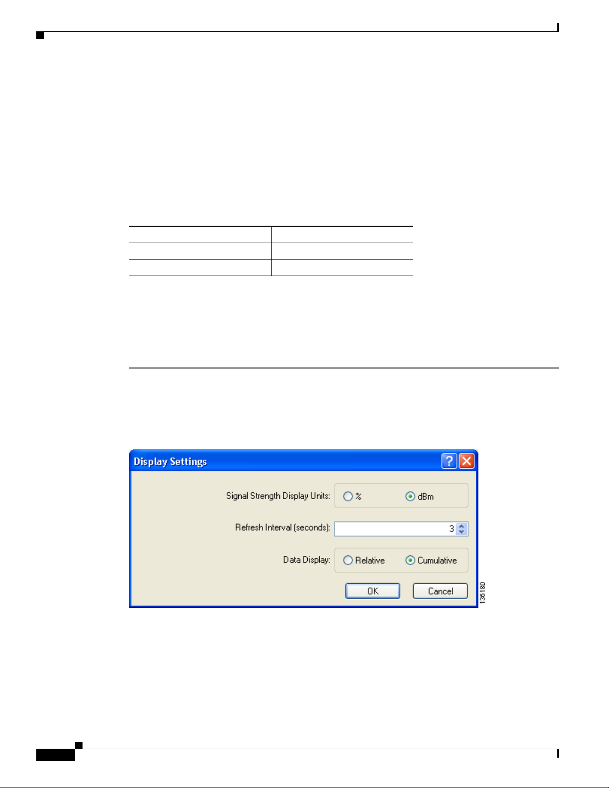
Step 2 Choose Display Settings from the Options drop-down menu. The Display Settings window appears (see
Figure 7-1).
Figure 7-1 Display Settings Window
7-2
Cisco Aironet 802.11a/b/g Wireless LAN Client Adapters (CB21AG and PI21AG) Installation and Configuration Guide
OL-4211-05
Page 3

Chapter 7 Viewing Status and Statistics
Step 3 Table 7-2 lists and describes the parameters that affect the operation of ADU status and statistics tools.
Follow the instructions in the table to change any parameters.
Table 7-2 Parameters Affecting ADU Status and Statistics Tools
Parameter Description
Signal Strength Display Units Specifies the units used to display signal strength on the Advanced
Refresh Interval Specifies how often the ADU status and statistics windows and the
Setting Parameters that Affect ADU Status and Statistics Tools
Status window and signal-to-noise ratio (SNR) on the Available
Infrastructure and Ad Hoc Networks window.
Options: % or dBm
Default: dBm
Units Description
% Displays the signal strength and
signal-to-noise ratio as a percentage.
dBm Displays the signal strength in decibels
with respect to milliwatts (dBm) and the
signal-to-noise ratio in decibels (dB).
ASTU icon are updated.
Range: 1 to 5 seconds between updates (in 1-second increments)
Data Display Specifies whether the data that is displayed on the Diagnostics and
Step 4 Click OK to save your changes.
Default: 3 seconds between updates
Advanced Statistics windows continue to increment until the driver is
reloaded or only until an update occurs (every 1 to 5 seconds).
Options: Relative or Cumulative
Default: Cumulative
Data Display Description
Relative Displays statistical data collected since the
last update, as specified by the Refresh
Interval (1 to 5 seconds).
Cumulative Displays statistical data collected since the
driver was loaded, upon card insertion or
reboot.
OL-4211-05
Cisco Aironet 802.11a/b/g Wireless LAN Client Adapters (CB21AG and PI21AG) Installation and Configuration Guide
7-3
Page 4
Chapter 7 Viewing Status and Statistics
Viewing the Current Status of Your Client Adapter
Viewing the Current Status of Your Client Adapter
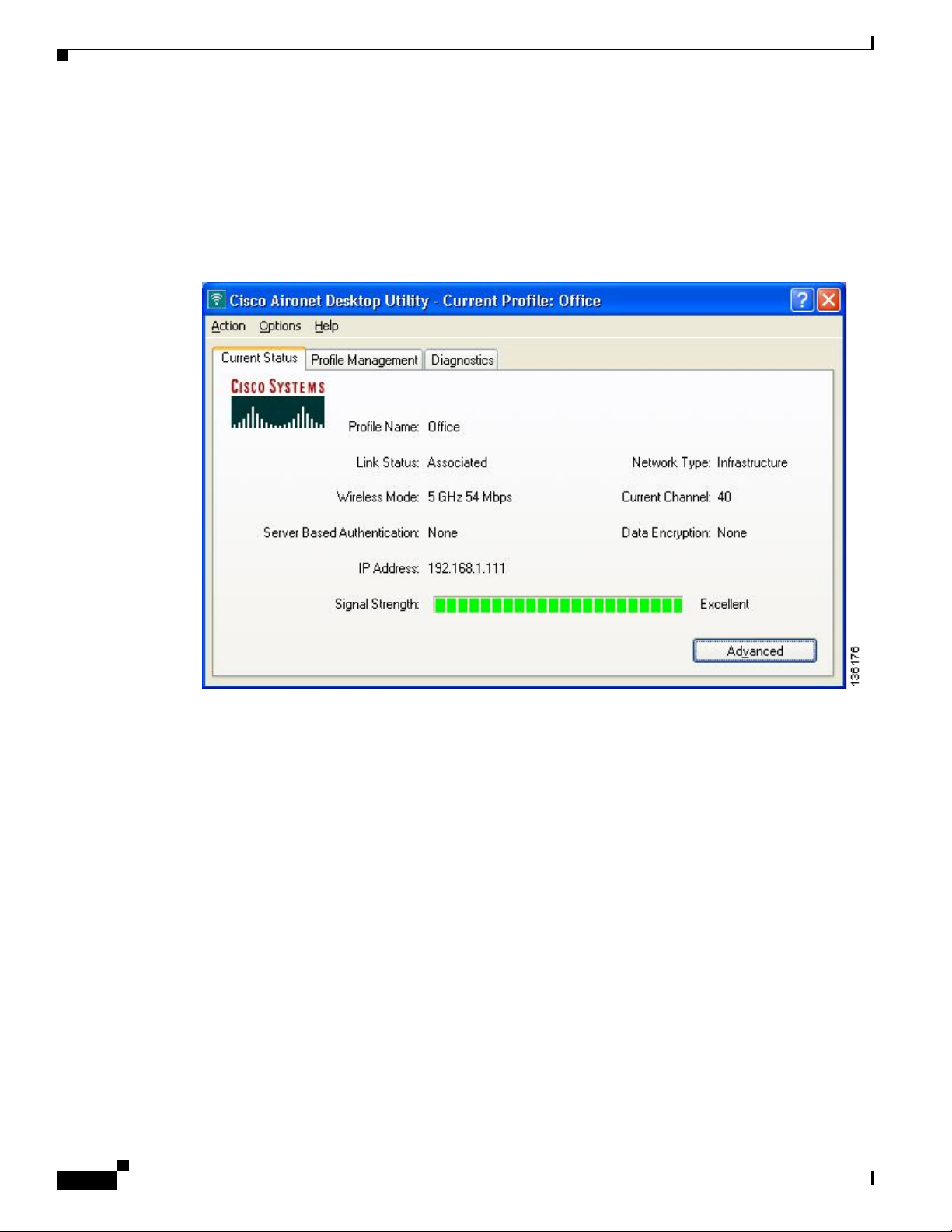
ADU enables you to view the current status of your client adapter as well as many of the settings that
have been configured for the adapter. To view your client adapter’s status and settings, open ADU. The
Current Status window appears (see Figure 7-2).
Figure 7-2 Current Status Window
7-4
Cisco Aironet 802.11a/b/g Wireless LAN Client Adapters (CB21AG and PI21AG) Installation and Configuration Guide
OL-4211-05
Page 5

Chapter 7 Viewing Status and Statistics
Table 7-3 interprets each element of the Current Status window.
Table 7-3 Basic Client Adapter Status
Status Description
Profile Name The network configuration (or profile) your client adapter is currently
Link Status The operational mode of your client adapter.
Wireless Mode The frequency and rate at which your current wireless connection is
Viewing the Current Status of Your Client Adapter
using.
Note Refer to Chapter 4 for information on creating, modifying, and
selecting profiles.
Val ue : Not Associated, Associated, Authenticating, Authenticated,
Authentication Failed, or Authentication Failed Retrying
Link Status Description
Not Associated The client adapter has not established a
connection to an access point (in
infrastructure mode) or another client (in
ad hoc mode).
Associated The client adapter has established a
connection to an access point (in
infrastructure mode) or another client (in
ad hoc mode).
Authenticating The client adapter is associated to an
access point, and the EAP authentication
process has begun but not yet succeeded.
Authenticated The client adapter is associated to an
access point, and the user is EAP
authenticated.
Authentication Failed The client adapter is associated to an
access point, but the user has failed to EAP
authenticate.
Authentication Failed
Retrying
The client adapter is associated to an
access point, the user has failed to EAP
authenticate, but another authentication
attempt is being made.
capable of transmitting or receiving packets.
OL-4211-05
Val ue : 5 GHz 54 Mbps, 2.4 GHz 11 Mbps, or 2.4 GHz 54 Mbps
Note Refer to the Wireless Mode parameter in Tab l e 5-3 for
information on setting the wireless mode for your client
adapter.
Network Type The type of network in which your client adapter is being used.
Val ue : Infrastructure or Ad Hoc
Note Refer to the Network Type parameter in Tab l e 5 - 3 for
information on setting the network type.
Cisco Aironet 802.11a/b/g Wireless LAN Client Adapters (CB21AG and PI21AG) Installation and Configuration Guide
7-5
Page 6

Viewing the Current Status of Your Client Adapter
Table 7-3 Basic Client Adapter Status (continued)
Status Description
Server Based Authentication The method by which authentication to a back-end server is being
IP Address The IP address of your client adapter.
Current Channel The channel that your client adapter is currently using for
Chapter 7 Viewing Status and Statistics
performed to establish secure connectivity.
Val ue : None, LEAP, EAP-FAST, EAP-TLS, PEAP (EAP-GTC),
PEAP (EAP-MSCHAP V2), or Host Based EAP
Note Refer to the “Overview of Security Features” on page 5-14 for
details on these server-based authentication types.
communications. This field displays Scanning while the client adapter
searches for a channel.
Val ue : Dependent on radio band and regulatory domain
Note Refer to the Channel parameter in Table 5-3 for information on
setting the channel for your client adapter.
Note Refer to Appendix D for a list of channel identifiers, channel
center frequencies, and regulatory domains for each channel.
Data Encryption The data encryption type that was negotiated with the access point (in
infrastructure mode) or another client (in ad hoc mode) upon
association.
Val ue : None, WEP, CKIP, TKIP, or AES
Note Refer to the “Overview of Security Features” on page 5-14 for
details on these data encryption types.
Signal Strength The signal strength for all received packets. The color of this
parameter’s progress bar provides a visual interpretation of signal
strength.
Val ue : Excellent (green), Good (green), Fair (yellow), Poor (red), or
No Link
7-6
Cisco Aironet 802.11a/b/g Wireless LAN Client Adapters (CB21AG and PI21AG) Installation and Configuration Guide
OL-4211-05
Page 7
Chapter 7 Viewing Status and Statistics
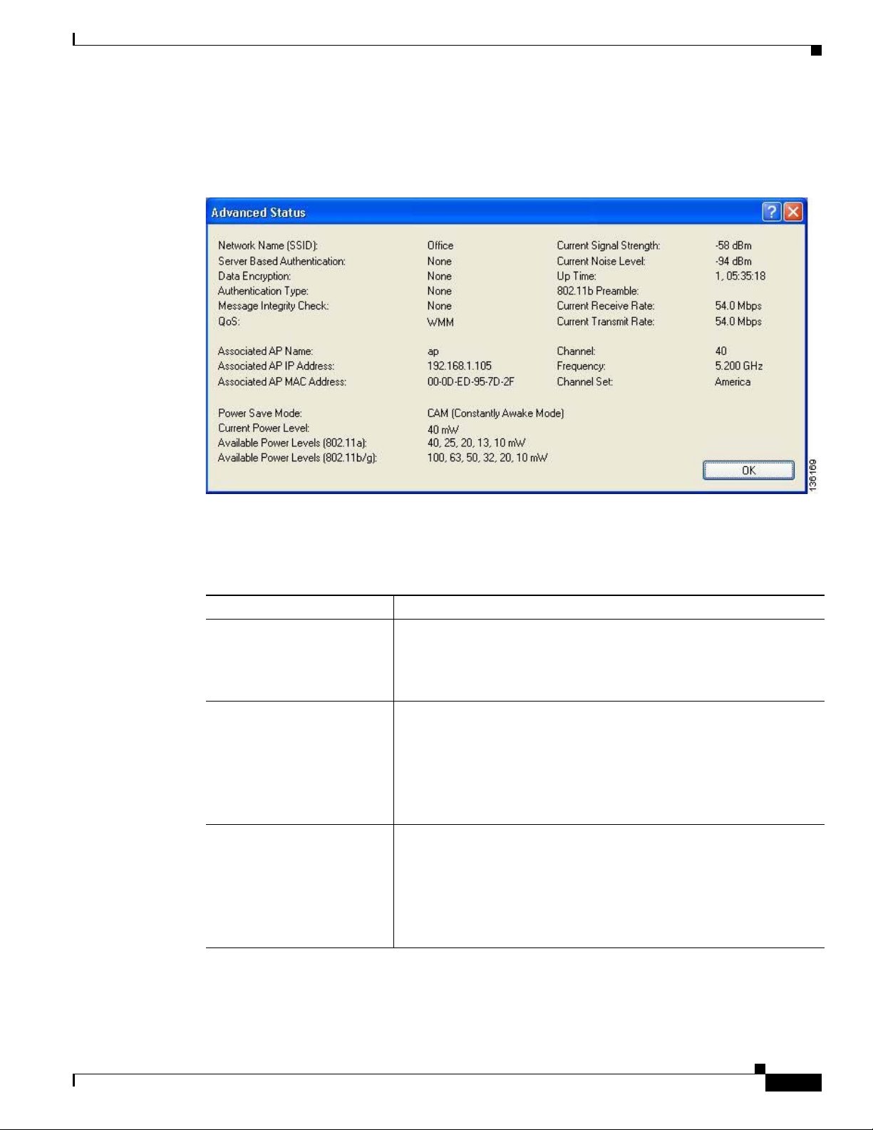
Click Advanced if you want to view more detailed status information for your client adapter. The
Advanced Status window appears (see Figure 7-3).
Figure 7-3 Advanced Status Window
Viewing the Current Status of Your Client Adapter
Table 7-4 interprets each element of the Advanced Status window.
Table 7-4 Advanced Client Adapter Status
Status Description
Network Name (SSID) The name of the network to which your client adapter is currently
associated.
Note Refer to the SSID1 parameter in Tab le 5-2 for information on
setting the client adapter’s SSID.
Server Based Authentication The method by which authentication to a back-end server is being
performed to establish secure connectivity.
Val ue : None, LEAP, EAP-FAST, EAP-TLS, PEAP (EAP-GTC),
PEAP (EAP-MSCHAP V2), or Host Based EAP
Refer to the “Overview of Security Features” on page 5-14 for details
on these server-based authentication types.
Data Encryption The data encryption type that was negotiated with the access point (in
infrastructure mode) or another client (in ad hoc mode) upon
association.
Val ue : None, WEP, CKIP, TKIP, or AES
Note Refer to the “Overview of Security Features” on page 5-14 for
details on these data encryption types.
OL-4211-05
Cisco Aironet 802.11a/b/g Wireless LAN Client Adapters (CB21AG and PI21AG) Installation and Configuration Guide
7-7
Page 8

Viewing the Current Status of Your Client Adapter
Table 7-4 Advanced Client Adapter Status (continued)
Status Description
Authentication Type Specifies whether the client adapter must share the same WEP keys as
Message Integrity Check Indicates whether your client adapter is using message integrity check
Chapter 7 Viewing Status and Statistics
the access point in order to authenticate or can authenticate to the
access point regardless of its WEP settings.
Val ue : Open or Shared
Note An incorrect WEP key setting prevents connectivity to the
network regardless of the 802.11 authentication type selected.
Note Refer to the “Setting Advanced Parameters” on page 5-6 for
information on setting the 802.11 authentication mode.
(MIC) to protect packets sent to and received from the access point.
MIC prevents bit-flip attacks on encrypted packets. During a bit-flip
attack, an intruder intercepts an encrypted message, alters it slightly,
and retransmits it, and the receiver accepts the retransmitted message
as legitimate.
Note MIC is supported automatically by the client adapter’s driver,
but it must be enabled on the access point.
Val ue : None, MMH, or Michael
Message Integrity Check Description
None MIC is disabled.
MMH MIC is enabled and is being used with
CKIP.
Michael MIC is enabled and is being used with
WPA and TKIP.
QoS The type of quality of service that is currently being used by your client
adapter. QoS on wireless LANs (WLAN) provides prioritization of
traffic from the access point over the WLAN based on traffic
classification.
Val ue : None or WMM
QoS Description
None WMM standard QoS is not enabled.
WMM Wi-Fi Multimedia, a component of the
IEEE 802.11e WLAN standard for QoS, is
enabled. For this value to appear, QoS and
WMM must be enabled on the access point
to which the client adapter is associated.
Note WMM is supported automatically in the client adapter
software. However, you must enable the Windows QoS Packet
Scheduler to ensure WMM support. Follow the instructions in
the “Enabling Wi-Fi Multimedia” on page 5-59 to enable the
QoS Packet Scheduler.
7-8
Cisco Aironet 802.11a/b/g Wireless LAN Client Adapters (CB21AG and PI21AG) Installation and Configuration Guide
OL-4211-05
Page 9

Chapter 7 Viewing Status and Statistics
Table 7-4 Advanced Client Adapter Status (continued)
Status Description
Associated AP Name The name of the access point to which your client adapter is associated.
Associated AP IP Address The IP address of the access point to which your client adapter is
Associated AP MAC Address The MAC address of the access point to which your client adapter is
Viewing the Current Status of Your Client Adapter
It is shown only if the client adapter is in infrastructure mode, the
access point was configured with a name, and Aironet Extensions are
enabled (on access points running Cisco IOS Release 12.2(4)JA or
later).
Note This field shows up to 15 characters although the name of the
access point may be longer.
associated. It is shown only if the client adapter is in infrastructure
mode, the access point was configured with an IP address, and Aironet
Extensions are enabled (on access points running Cisco IOS Release
12.2(4)JA or later).
Note If Aironet Extensions are disabled, the IP address of the
associated access point is shown as 0.0.0.0.
associated. It is shown only if the client adapter is in infrastructure
mode.
Note This field displays the MAC address of the access point’s
Ethernet port (for access points that do not run Cisco IOS
software) or the MAC address of the access point’s radio (for
access points that run Cisco IOS software). The MAC address
of the Ethernet port on access points that run Cisco IOS
software is printed on a label on the back of the device.
Power Save Mode The client adapter’s current power consumption setting.
Val ue : CAM (Constantly Awake Mode), Max PSP (Max Power
Saving), or Fast PSP (Power Save Mode)
Note Refer to the Power Save Mode parameter in Table 5-3 for
information on setting the client adapter’s power save mode.
Current Power Level The power level at which your client adapter is currently transmitting.
The maximum level is dependent upon the radio band used and your
country’s regulatory agency.
Val ue : 10, 13, 20, 25, or 40 mW (802.11a band);
10, 20, 32, 50, 63, or 100 mW (802.11b/g band)
Note Refer to the Transmit Power Level parameter in Table 5-3 for
information on setting the client adapter’s power level.
Available Power Levels The power levels at which your client adapter is capable of
transmitting. The maximum level is dependent upon the radio band
used and your country’s regulatory agency.
OL-4211-05
Val ue : 10, 13, 20, 25, or 40 mW (802.11a band);
10, 20, 32, 50, 63, or 100 mW (802.11b/g band)
Note Refer to the Transmit Power Level parameter in Table 5-3 for
information on the client adapter’s available power levels.
Cisco Aironet 802.11a/b/g Wireless LAN Client Adapters (CB21AG and PI21AG) Installation and Configuration Guide
7-9
Page 10

Viewing the Current Status of Your Client Adapter
Table 7-4 Advanced Client Adapter Status (continued)
Status Description
Current Signal Strength The signal strength for all received packets. The higher the value, the
Current Signal Quality The signal quality for all received packets. The higher the value, the
Current Noise Level The level of background radio frequency energy in the current radio
Up Time The amount of time (in hours:minutes:seconds) since the client adapter
802.11b Preamble Indicates whether your client adapter is using only long radio headers
Chapter 7 Viewing Status and Statistics
stronger the signal.
Range: 0 to 100% or 0 to –100 dBm
clearer the signal.
Range: 0 to 100%
Note This field appears only if you selected signal strength to be
displayed as a percentage. See the Signal Strength Display
Units parameter in Tab le 7-2 for information.
band. The lower the value, the less background noise present.
Range: 0 to –100 dBm
Note This field appears only if you selected signal strength to be
displayed in dBm. See the Signal Strength Display Units
parameter in Tabl e 7-2 for information.
has been receiving power. If the adapter has been running for more than
24 hours, the time is displayed in days, hours:minutes:seconds.
or short and long radio headers.
Val ue : Short & Long or Long Only
Note This field contains a value only when the client adapter is
operated in 2.4-GHz 11-Mbps or 2.4-GHz 54-Mbps mode.
Note Refer to the 802.11b Preamble parameter in Tabl e 5- 3 for
information on using radio headers.
Current Receive Rate The rate at which your client adapter is currently receiving data
packets.
Val ue : 1, 2, 5.5, 6, 9, 11, 12, 18, 24, 36, 48, or 54 Mbps
Current Transmit Rate The rate at which your client adapter is currently transmitting data
packets.
Val ue : 1, 2, 5.5, 6, 9, 11, 12, 18, 24, 36, 48, or 54 Mbps
Channel The channel that your client adapter is currently using for
communications. This field displays Scanning while the client adapter
searches for a channel.
Val ue : Dependent on radio band and regulatory domain
Note Refer to the Channel parameter in Table 5-3 for information on
setting the channel for your client adapter.
Note Refer to Appendix D for a list of channel identifiers, channel
center frequencies, and regulatory domains for each channel.
7-10
Cisco Aironet 802.11a/b/g Wireless LAN Client Adapters (CB21AG and PI21AG) Installation and Configuration Guide
OL-4211-05
Page 11

Chapter 7 Viewing Status and Statistics
Table 7-4 Advanced Client Adapter Status (continued)
Status Description
Frequency The radio frequency that your client adapter is currently using for
Channel Set The regulatory domain for which your client adapter is currently
Click OK to close the Advanced Status window.
Viewing the Current Status of Your Client Adapter
communications. This field displays Scanning while the client adapter
searches for a frequency.
Val ue : Dependent on radio band and regulatory domain
Note Refer to the Wireless Mode parameter in Tab l e 5-3 for
information on setting the frequency for your client adapter.
configured. This value is not user selectable.
Val ue : America, EMEA, Japan, or Rest of World
Note Refer to Appendix D for a list of channel identifiers, channel
center frequencies, and regulatory domains for each channel.
OL-4211-05
Cisco Aironet 802.11a/b/g Wireless LAN Client Adapters (CB21AG and PI21AG) Installation and Configuration Guide
7-11
Page 12
Viewing Statistics for Your Client Adapter
Viewing Statistics for Your Client Adapter
ADU enables you to view statistics that indicate how data is being received and transmitted by your
client adapter.
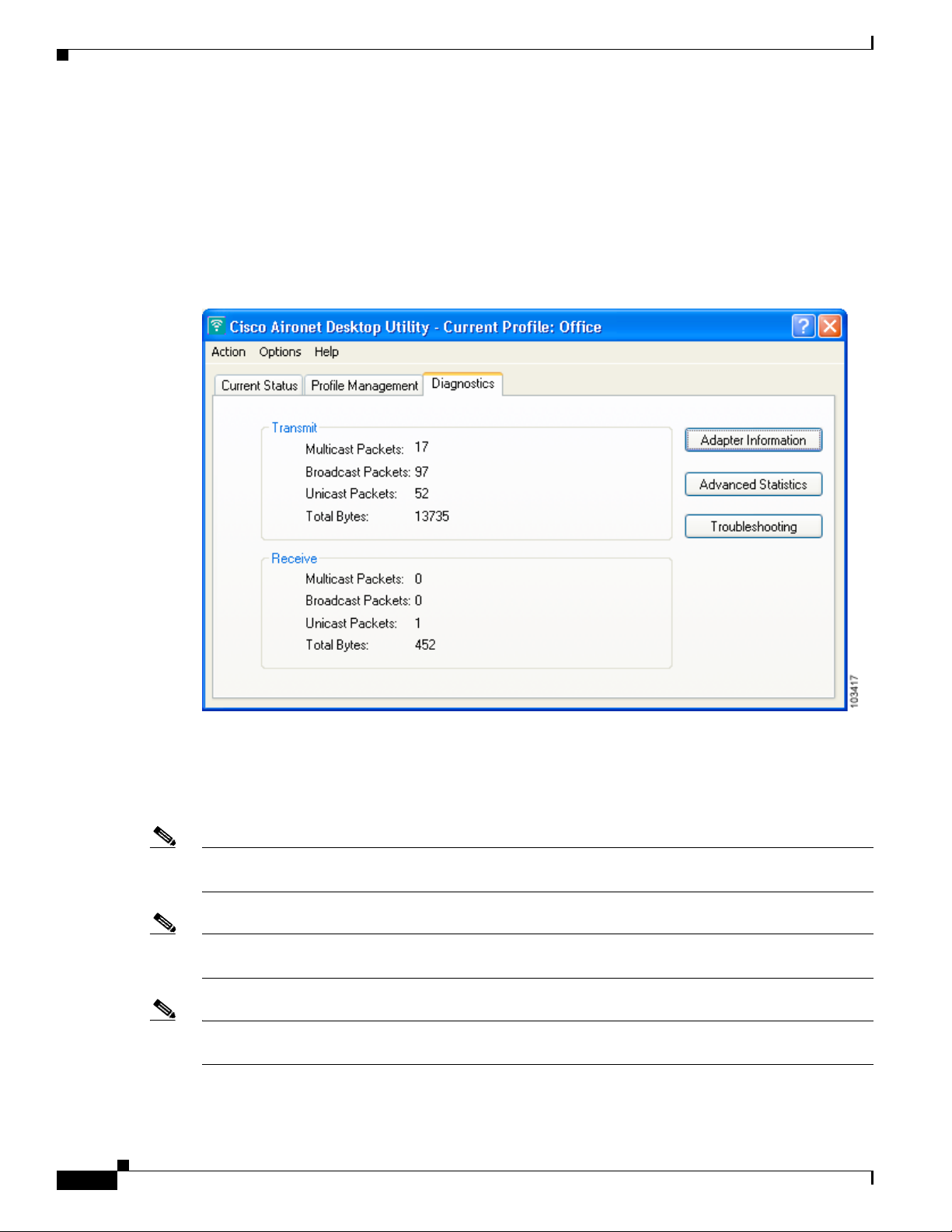
To view your client adapter’s statistics, open ADU and click the Diagnostics tab. The Cisco Aironet
Desktop Utility (Diagnostics) window appears (see Figure 7-4).
Figure 7-4 Cisco Aironet Desktop Utility (Diagnostics) Window
Chapter 7 Viewing Status and Statistics
7-12
This window displays basic transmit and receive statistics for your client adapter. The statistics are
calculated on a relative or cumulative basis as specified by the Data Display parameter and are
continually updated at the rate specified by the Refresh Interval parameter. Instructions for changing the
Data Display and Refresh Interval settings are provided in Tabl e 7- 2 .
Note The receive and transmit statistics are host statistics. That is, they show packets and errors received or
sent by the Windows device.
Note To run the Cisco Aironet Troubleshooting Utility, click Troubleshooting. Refer to “Using the Cisco
Aironet Troubleshooting Utility” on page 10-3 for more information.
Note To view client adapter information, click Adapter Information. Refer to “Viewing Client Adapter
Information” on page 9-10 for more information.
Cisco Aironet 802.11a/b/g Wireless LAN Client Adapters (CB21AG and PI21AG) Installation and Configuration Guide
OL-4211-05
Page 13
Chapter 7 Viewing Status and Statistics
Table 7-5 describes each statistic that is displayed for your client adapter.
Table 7-5 Basic Client Adapter Statistics
Statistic Description
Transmit Statistics
Multicast Packets The number of multicast packets that were transmitted.
Broadcast Packets The number of broadcast packets that were transmitted.
Unicast Packets The number of unicast packets that were transmitted successfully.
Total Bytes The number of bytes of data that were transmitted successfully.
Receive Statistics
Multicast Packets The number of multicast packets that were received.
Broadcast Packets The number of broadcast packets that were received.
Unicast Packets The number of unicast packets that were received successfully.
Total Bytes The number of bytes of data that were received successfully.
Viewing Statistics for Your Client Adapter
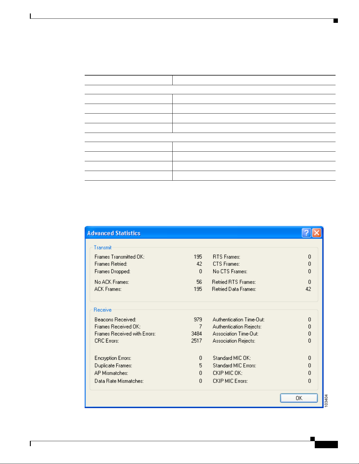
Click Advanced Statistics if you want to view additional statistics for your client adapter. The
Advanced Statistics window appears (see Figure 7-5).
Figure 7-5 Advanced Statistics Window
OL-4211-05
Cisco Aironet 802.11a/b/g Wireless LAN Client Adapters (CB21AG and PI21AG) Installation and Configuration Guide
7-13
Page 14

Viewing Statistics for Your Client Adapter
Table 7-6 interprets each element of the Advanced Statistics window.
Table 7-6 Advanced Client Adapter Statistics
Status Description
Transmit Statistics
Frames Transmitted OK The number of frames that were transmitted successfully.
Frames Retried The number of frames that were retried.
Frames Dropped The number of frames that were dropped because of errors or
No ACK Frames The number of transmitted frames that did not have their corresponding
ACK Frames The number of transmitted frames that had their corresponding Ack
RTS Frames The number of request-to-send (RTS) transmissions that were
CTS Frames The number of clear-to-send (CTS) frames that were received in
No CTS Frames The number of request-to-send (RTS) transmissions that were
Retried RTS Frames The number of request-to-send (RTS) frames that were retransmitted.
Retried Data Frames The number of normal data frames that were retransmitted.
Receive Statistics
Beacons Received The number of beacon frames that were received successfully.
Frames Received OK The number of all frames that were received successfully.
Frames Received with Errors The number of frames that were received with an invalid checksum.
CRC Errors The number of cyclic redundancy check (CRC) errors detected in the
Encryption Errors The number of frames that were received with encryption errors.
Duplicate Frames The number of duplicate frames that were received.
AP Mismatches The number of times the client adapter tried to associate to an access
Chapter 7 Viewing Status and Statistics
collisions.
Ack frame received successfully.
frame received successfully.
attempted.
response to a successfully transmitted RTS frame.
unsuccessful. The access point sends CTS frames in response to the
client’s RTS frames. This field keeps track of each time the client does
not receive a CTS back from the access point.
data portion of the frame.
point but was unable to because the access point was not the adapter’s
specified access point.
7-14
Note Refer to the Access Point 1 through Access Point 4 parameters
on page 5-13 for information on specifying access points.
Data Rate Mismatches The number of times the client adapter tried to associate to an access
point but was unable to because the adapter’s data rate was not
supported by the access point.
Note Refer to the Wireless Mode parameter in Tab le 5-3 for
information on supported data rates.
Cisco Aironet 802.11a/b/g Wireless LAN Client Adapters (CB21AG and PI21AG) Installation and Configuration Guide
OL-4211-05
Page 15

Chapter 7 Viewing Status and Statistics
Table 7-6 Advanced Client Adapter Statistics (continued)
Status Description
Authentication Time-Out The number of times the client adapter tried to authenticate to an access
Authentication Rejects The number of times the client adapter tried to authenticate to an access
Association Time-Out The number of times the client adapter tried to associate to an access
Association Rejects The number of times the client adapter tried to associate to an access
Standard MIC OK The number of frames that were received with the correct message
Standard MIC Errors The number of frames that were discarded due to an incorrect message
CKIP MIC OK The number of frames that were received with the correct message
CKIP MIC Errors The number of frames that were discarded due to an incorrect message
Viewing Statistics for Your Client Adapter
point but was unable to because the access point did not respond fast
enough (timed out).
point but was rejected.
point but was unable to because the access point did not respond fast
enough (timed out).
point but was rejected.
integrity check (MIC) value.
integrity check (MIC) value.
integrity check (MIC) value when CKIP was being used.
Note This field is displayed only if MIC is enabled on the access
point.
integrity check (MIC) value when CKIP was being used.
Note This field is displayed only if MIC is enabled on the access
point.
Click OK to close the Advanced Statistics window.
OL-4211-05
Cisco Aironet 802.11a/b/g Wireless LAN Client Adapters (CB21AG and PI21AG) Installation and Configuration Guide
7-15
Page 16

Viewing Statistics for Your Client Adapter
Chapter 7 Viewing Status and Statistics
7-16
Cisco Aironet 802.11a/b/g Wireless LAN Client Adapters (CB21AG and PI21AG) Installation and Configuration Guide
OL-4211-05
Page 17

CHAPTER
8
Using the Aironet System Tray Utility (ASTU)
This chapter explains how to use the Aironet System Tray Utility (ASTU) to access status information
about your client adapter and perform basic tasks.
The following topics are covered in this chapter:
• Overview of ASTU, page 8-2
• The ASTU Icon, page 8-2
• Tool Tip Window, page 8-3
• Pop-Up Menu, page 8-5
OL-4211-05
Cisco Aironet 802.11a/b/g Wireless LAN Client Adapters (CB21AG and PI21AG) Installation and Configuration Guide
8-1
Page 18
Overview of ASTU
Overview of ASTU
ASTU is an optional application that provides a small subset of the features available through ADU.
Specifically, it enables you to access status information about your client adapter and perform basic
tasks. ASTU is accessible from an icon in the Windows system tray, making it easily accessible and
convenient to use. The ASTU icon appears only if a client adapter is installed into your computer and
you did not disable ASTU during installation.
ASTU provides information and options in the following ways:
• In the appearance of the icon itself
• Through a tool tip window that appears when you hover the cursor over the icon
• Through a pop-up menu that appears when you right-click the icon
• Through a Connection Status window that appears when you double-click the icon
The ASTU Icon
Chapter 8 Using the Aironet System Tray Utility (ASTU)
The appearance of the ASTU icon indicates the connection status of your client adapter. ASTU reads the
client adapter status and updates the icon every 1 to 5 seconds, depending on the value entered for the
Refresh Interval on the Display Settings window. Ta ble 8-1 interprets the different appearances of the
ASTU icon.
Note Windows 2000 and XP may display their own wireless network connection status icon in the system tray.
Cisco recommends that you turn off the Windows icon and use the ASTU icon to monitor your wireless
connection.
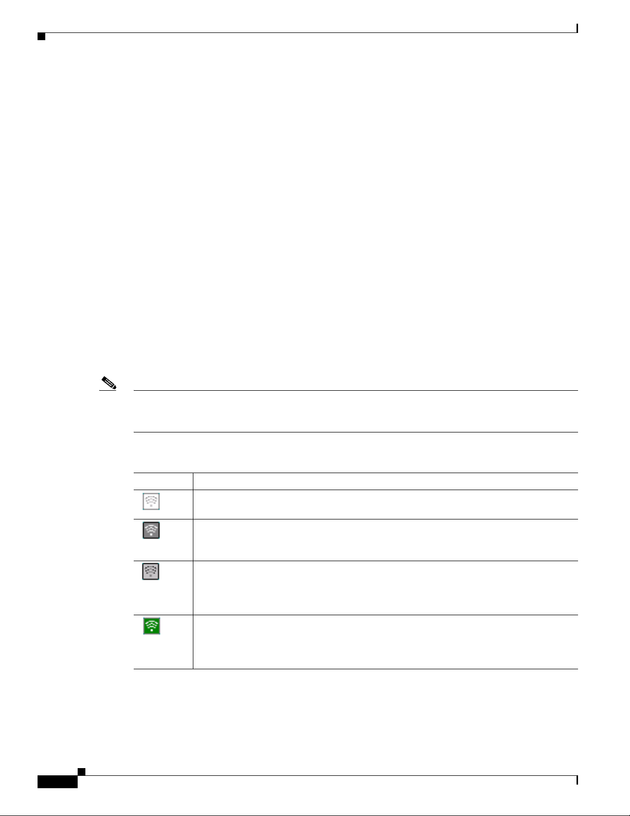
Table 8-1 Interpreting the ASTU Icon
Icon Description
A white icon indicates that the client adapter’s radio is disabled.
A dark gray icon indicates that the client adapter is not associated to an access point (in
infrastructure mode) or another client (in ad hoc mode).
A light gray icon indicates that the client adapter is associated to an access point (in
infrastructure mode) or another client (in ad hoc mode) but the user is not EAP
authenticated.
A green icon indicates that the client adapter is associated to an access point (in
infrastructure mode) or another client (in ad hoc mode), the user is authenticated if the
client adapter is configured for EAP authentication, and the signal strength is excellent
or good.
8-2
Cisco Aironet 802.11a/b/g Wireless LAN Client Adapters (CB21AG and PI21AG) Installation and Configuration Guide
OL-4211-05
Page 19
Chapter 8 Using the Aironet System Tray Utility (ASTU)
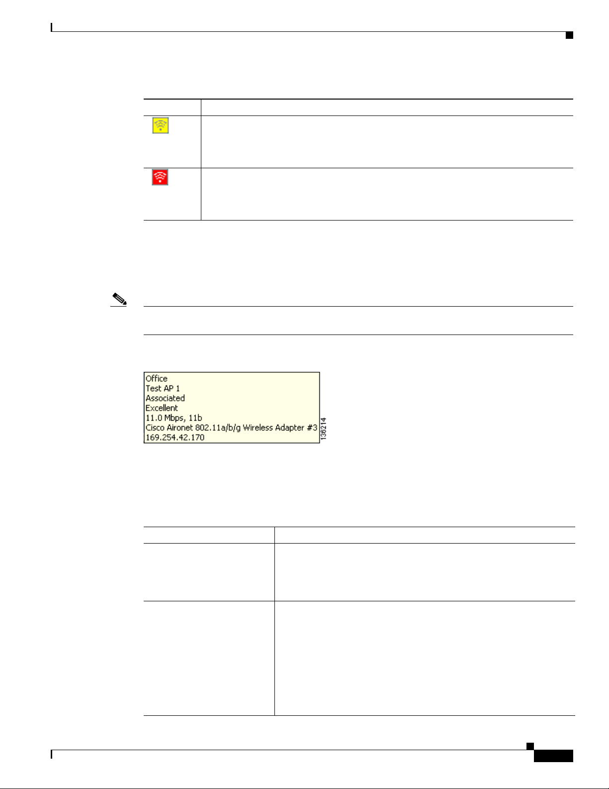
Table 8-1 Interpreting the ASTU Icon (continued)
Icon Description
A yellow icon indicates that the client adapter is associated to an access point (in
infrastructure mode) or another client (in ad hoc mode), the user is authenticated if the
client adapter is configured for EAP authentication, and the signal strength is fair.
A red icon indicates that the client adapter is associated to an access point (in
infrastructure mode) or another client (in ad hoc mode), the user is authenticated if the
client adapter is configured for EAP authentication, and the signal strength is poor.
Tool Tip Window
When you hover the cursor over the ASTU icon, the Tool Tip window appears (see Figure 8-1).
Note If the client adapter’s radio is disabled, a message appears instead of the Tool Tip window to inform you
that the wireless network interface is disabled.
Tool Tip Window
Figure 8-1 Tool Tip Window
This window provides information on the current status of your client adapter. Tab l e 8 - 2 lists and
describes each element of the Tool Tip window.
Table 8-2 Tool Tip Window Elements
Status Element Description
Active profile The network configuration (or profile) that your client adapter is
currently using.
Note If auto profile selection is enabled, the active profile does not
appear until the client is associated to an access point.
SSID The name of the network to which your client adapter is currently
associated.
Note When the client adapter is not associated and auto profile
selection is disabled, this field shows the profile’s SSID. When
the client adapter is not associated and auto profile selection is
enabled, this field is left blank.
OL-4211-05
Note Refer to the SSID1 parameter in Tab le 5-2 for information on
setting the client adapter's SSID.
Cisco Aironet 802.11a/b/g Wireless LAN Client Adapters (CB21AG and PI21AG) Installation and Configuration Guide
8-3
Page 20

Tool Tip Window
Chapter 8 Using the Aironet System Tray Utility (ASTU)
Table 8-2 Tool Tip Window Elements (continued)
Status Element Description
Connection status The operational mode of your client adapter.
Val ue : Not Associated, Associated, Authenticating, Authenticated,
Authentication Failed, or Authentication Failed Retrying
Connection Status Description
Not Associated The client adapter has not established a
connection to an access point (in
infrastructure mode) or another client (in
ad hoc mode).
Associated The client adapter has established a
connection to an access point (in
infrastructure mode) or another client (in
ad hoc mode).
Authenticating The client adapter is associated to an
access point, and the EAP authentication
process has begun but not yet succeeded.
Authenticated The client adapter is associated to an
access point, and the user is EAP
authenticated.
Authentication Failed The client adapter is associated to an
access point, but the user has failed to EAP
authenticate.
Authentication Failed
Retrying
Note This status may appear very
briefly or not at all as the
authentication failure may result
in the client adapter becoming
disassociated, in which case the
status reads Not Associated.
The client adapter is associated to an
access point, the user has failed to EAP
authenticate, but another authentication
attempt is being made.
Note This status may appear very
briefly or not at all as the
authentication failure may result
in the client adapter becoming
disassociated, in which case the
status reads Not Associated.
8-4
Cisco Aironet 802.11a/b/g Wireless LAN Client Adapters (CB21AG and PI21AG) Installation and Configuration Guide
OL-4211-05
Page 21
Chapter 8 Using the Aironet System Tray Utility (ASTU)
Table 8-2 Tool Tip Window Elements (continued)
Status Element Description
Link quality The client adapter's signal strength for all received packets.
Link speed and 802.11 mode The rate at which your client adapter is currently transmitting data
Client adapter type A description of your client adapter.
Client adapter IP address The IP address of your client adapter.
Pop-Up Menu
Pop-Up Menu
Val ue : Excellent, Good, Fair, Poor, or No Link
packets and the 802.11 mode that your client adapter is currently using
for communications.
Link speed value:1, 2, 5.5, 6, 9, 11, 12, 18, 24, 36, 48, or 54 Mbps
802.11 mode value: 11a, 11b, or 11g
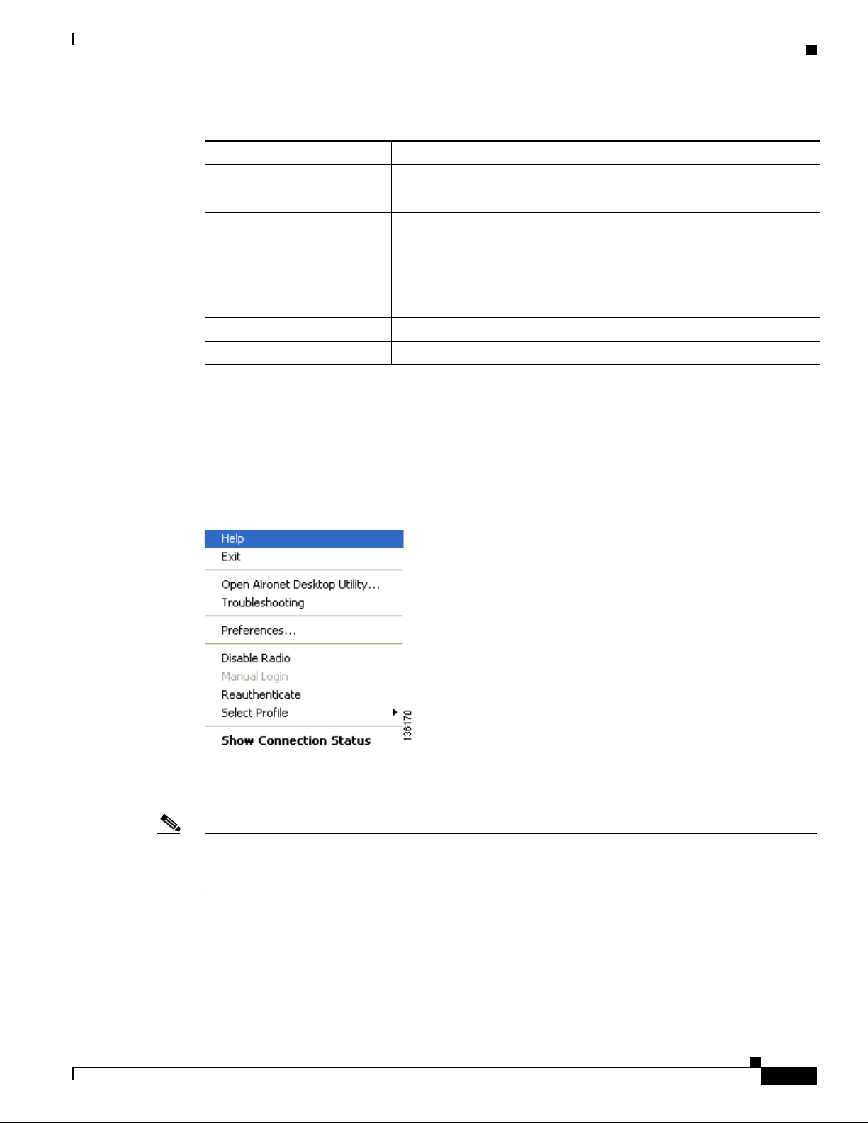
When you right-click the ASTU icon, the ASTU pop-up menu appears (see Figure 8-2).
Figure 8-2 ASTU Pop-Up Menu
The following sections describe each ASTU pop-up menu option.
Note If you used the Aironet System Tray Utility Preferences window or your system administrator used an
administrative tool to deactivate certain ASTU menu options, these options do not appear in the menu
and therefore cannot be selected.
Help
OL-4211-05
This option enables you to access the online help.
Cisco Aironet 802.11a/b/g Wireless LAN Client Adapters (CB21AG and PI21AG) Installation and Configuration Guide
8-5
Page 22
Pop-Up Menu
Exit
This option closes ADU and ASTU.
Note To reactivate ADU, double-click the Aironet Desktop Utility icon on your computer desktop. To
reactivate ASTU, choose the Enable Tray Icon option from the ADU Action drop-down menu.
Open Aironet Desktop Utility
This option activates ADU.
Troubleshooting
This option activates the troubleshooting utility, which enables you to identify and resolve configuration
and association problems with your client adapter. Refer to the “Using the Cisco Aironet
Troubleshooting Utility” section on page 10-3 for detailed instructions on using this utility.
Chapter 8 Using the Aironet System Tray Utility (ASTU)
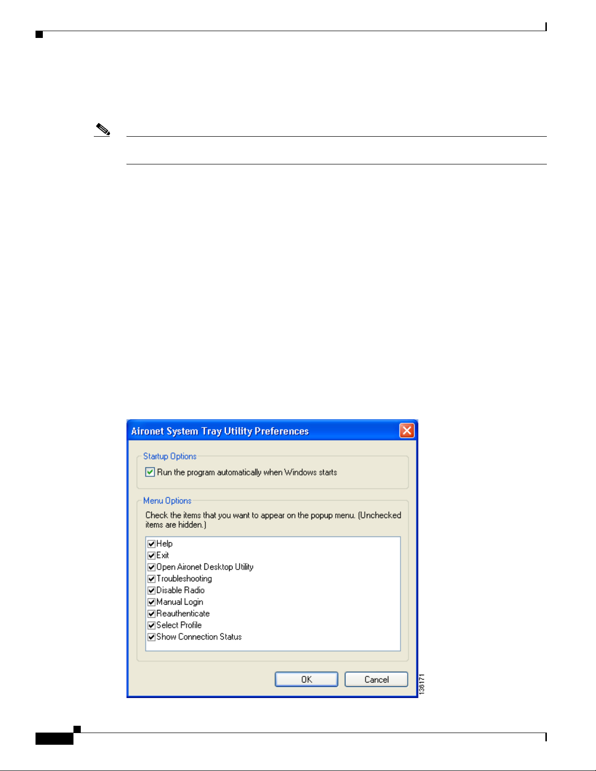
Preferences
When you choose this option, the Aironet System Tray Utility Preferences window appears (see
Figure 8-3).
Figure 8-3 Aironet System Tray Utility Preferences Window
8-6
Cisco Aironet 802.11a/b/g Wireless LAN Client Adapters (CB21AG and PI21AG) Installation and Configuration Guide
OL-4211-05
Page 23

Chapter 8 Using the Aironet System Tray Utility (ASTU)
This window enables you to determine when ADU and ASTU run and to choose the options that appear
on the ASTU pop-up menu. Follow these steps to make your selections.
Step 1 If you want ASTU to run automatically when Windows starts, make sure the Run the program
automatically when Windows starts check box is checked. Otherwise, uncheck this check box.
Note If you do not choose this option and later want to run ASTU, you must choose the Enable Tray
Icon option from the Action drop-down menu in ADU.
Step 2 In the Menu Options portion of the window, make sure the check boxes of all the options that you want
to appear in the ASTU pop-up menu are checked. Any options that are not checked will not be included
in the menu.
Note The Preferences option cannot be deselected. It always appears in the ASTU pop-up menu.
Step 3 Click OK to save your changes.
Pop-Up Menu
Enable/Disable Radio
This option enables you to disable or enable the client adapter’s radio. Disabling the radio prevents the
adapter from transmitting RF energy. You might want to disable the client adapter’s radio in the
following situations:
• You are not transmitting data and want to conserve battery power.
• You are using a laptop on an airplane, hospital, or any other location where radio transmission is not
allowed and want to prevent the adapter’s transmissions from potentially interfering with the
operation of certain devices.
When the radio is enabled, it periodically sends out probes even if it is not associated to an access point
(in infrastructure mode) or another client (in ad hoc mode), as required by the 802.11 specification.
Therefore, it is important to disable it around devices that are susceptible to RF interference.
Note If the client adapter’s radio is disabled, your client adapter is not associated, and a message appears when
you hover the cursor over the ASTU icon to inform you that the wireless network interface is disabled.
Note If your client adapter’s radio is disabled before your computer enters standby or hibernate mode or
before you reboot the computer, the radio remains disabled when the computer resumes. You must enable
the radio to resume operation.
If the radio is enabled, choose Disable Radio to disable the radio.
OL-4211-05
If the radio is disabled, choose Enable Radio to enable the radio.
Cisco Aironet 802.11a/b/g Wireless LAN Client Adapters (CB21AG and PI21AG) Installation and Configuration Guide
8-7
Page 24
Pop-Up Menu
Manual Login
This option enables you to manually invoke the authentication process for a profile that is configured to
use a manually prompted LEAP or EAP-FAST username and password. When you choose this option,
the Enter Wireless Network Password window appears. Enter your LEAP or EAP-FAST credentials and
click OK. The LEAP or EAP-FAST Authentication Status window appears, and the authentication
process begins.
Note Refer to Chapter 5 for information on setting a manual LEAP or EAP-FAST profile and Chapter 6 for
details on the authentication process.
Reauthenticate
This option forces your client adapter to try to reauthenticate using the username and password of the
current profile. It is available for all EAP-enabled profiles. When you choose this option, the
authentication process begins.
Chapter 8 Using the Aironet System Tray Utility (ASTU)
Select Profile
If your client adapter is unable to authenticate using the specified username and password, you may be
prompted to re-enter them. If you click Cancel, a message appears indicating that the current profile will
be disabled until you choose the Reauthenticate option, reboot your computer, or eject and reinsert the
client adapter.
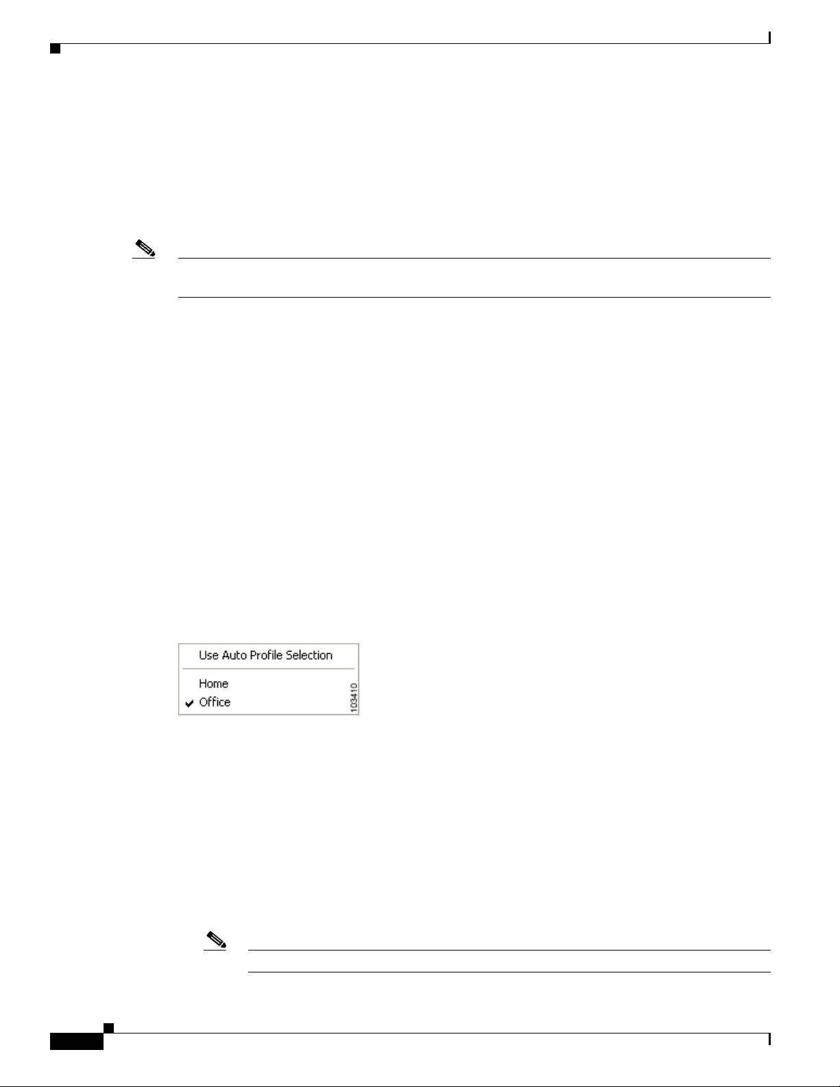
This option enables you to select the active profile for your client adapter. When you choose this option,
a profiles submenu appears (see Figure 8-4).
Figure 8-4 Profiles Submenu
From this menu, you can choose between the following options:
• Use Auto Profile Selection—Causes the client adapter’s driver to automatically select a profile
from the list of profiles that were set up in ADU to be included in auto profile selection.
If the client adapter loses association for more than 10 seconds (or for more than the time specified
by the LEAP/EAP-FAST authentication timeout value on the LEAP/EAP-FAST Settings window if
LEAP/EAP-FAST is enabled), the driver switches automatically to another profile that is included
in auto profile selection. The adapter will not switch profiles as long as it remains associated or
reassociates within 10 seconds (or within the time specified by the LEAP/EAP-FAST authentication
timeout value). To force the client adapter to associate to a different access point (in infrastructure
mode) or another client (in ad hoc mode), you must select a new profile.
8-8
Note This option is available only if two or more profiles are included in auto profile selection.
Cisco Aironet 802.11a/b/g Wireless LAN Client Adapters (CB21AG and PI21AG) Installation and Configuration Guide
OL-4211-05
Page 25
Chapter 8 Using the Aironet System Tray Utility (ASTU)
Note Login scripts are not reliable if you use auto profile selection with LEAP or EAP-FAST. If
you authenticate and achieve full network connectivity before or at the same time as you log
into the computer, the login scripts will run. However, if you authenticate and achieve full
network connectivity after you log into the computer, the login scripts will not run.
• A specific profile—When you select a profile from the list of available profiles, the client adapter
attempts to establish a connection to an access point (in infrastructure mode) or another client (in
ad hoc mode) using the parameters that were configured for that profile.
If the client adapter cannot associate to the access point (or other client) or loses association while
using the selected profile, the adapter does not attempt to associate using another profile. To get it
to associate, you must select a different profile or select Use Auto Profile Selection.
Simply click the desired profile to select it. A check mark appears beside the profile, and the client
adapter attempts to establish a connection using the selected profile.
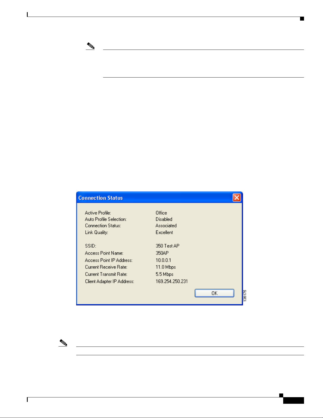
Show Connection Status
Pop-Up Menu
When you choose this option, the Connection Status window appears (see Figure 8-5).
Figure 8-5 Connection Status Window
OL-4211-05
This window provides information on the current status of your client adapter. Table 8-3 interprets each
element of the Connection Status window.
Note You can also access the Connection Status window by double-clicking the ASTU icon.
Cisco Aironet 802.11a/b/g Wireless LAN Client Adapters (CB21AG and PI21AG) Installation and Configuration Guide
8-9
Page 26

Pop-Up Menu
Chapter 8 Using the Aironet System Tray Utility (ASTU)
Table 8-3 Connection Status Window Elements
Status Element Description
Active Profile The network configuration (or profile) that your client adapter is
currently using.
Auto Profile Selection Indicates whether your client adapter is using auto profile selection.
Val ue : Enabled or Disabled
Connection Status The operational mode of your client adapter.
Val ue : Not Associated, Associated, Authenticating, Authenticated,
Authentication Failed, or Authentication Failed Retrying
Connection Status Description
Not Associated The client adapter has not established a
connection to an access point (in
infrastructure mode) or another client (in
ad hoc mode).
Associated The client adapter has established a
connection to an access point (in
infrastructure mode) or another client (in
ad hoc mode).
Authenticating The client adapter is associated to an
access point, and the EAP authentication
process has begun but not yet succeeded.
Authenticated The client adapter is associated to an
access point, and the user is EAP
authenticated.
Authentication Failed The client adapter is associated to an
access point, but the user has failed to EAP
authenticate.
8-10
Note This status may appear very
briefly or not at all as the
authentication failure may result
in the client adapter becoming
disassociated, in which case the
status reads Not Associated.
Authentication Failed
Retrying
The client adapter is associated to an
access point, the user has failed to EAP
authenticate, but another authentication
attempt is being made.
Note This status may appear very
briefly or not at all as the
authentication failure may result
in the client adapter becoming
disassociated, in which case the
status reads Not Associated.
Cisco Aironet 802.11a/b/g Wireless LAN Client Adapters (CB21AG and PI21AG) Installation and Configuration Guide
OL-4211-05
Page 27

Chapter 8 Using the Aironet System Tray Utility (ASTU)
Table 8-3 Connection Status Window Elements (continued)
Status Element Description
Link Quality The client adapter’s signal strength for all received packets.
SSID The name of the network to which your client adapter is currently
Access Point Name The name of the access point to which your client adapter is associated.
Access Point IP Address The IP address of the access point to which your client adapter is
Pop-Up Menu
Val ue : Excellent, Good, Fair, Poor, or No Link
associated.
Note Refer to the SSID1 parameter in Tab le 5-2 for information on
setting the client adapter’s SSID.
It is shown only if the client adapter is in infrastructure mode, the
access point was configured with a name, and Aironet Extensions are
enabled (on access points running Cisco IOS Release 12.2(4)JA or
later).
Note This field shows up to 15 characters although the name of the
access point may be longer.
associated. It is shown only if the client adapter is in infrastructure
mode, the access point was configured with an IP address, and Aironet
Extensions are enabled (on access points running Cisco IOS Release
12.2(4)JA or later).
Note If Aironet Extensions are disabled, the IP address of the
associated access point is shown as 0.0.0.0.
Current Receive Rate The rate at which your client adapter is currently receiving data
packets.
Val ue : 1, 2, 5.5, 6, 9, 11, 12, 18, 24, 36, 48, or 54 Mbps
Current Transmit Rate The rate at which your client adapter is currently transmitting data
packets.
Val ue : 1, 2, 5.5, 6, 9, 11, 12, 18, 24, 36, 48, or 54 Mbps
Client Adapter IP Address The IP address of your client adapter.
OL-4211-05
Cisco Aironet 802.11a/b/g Wireless LAN Client Adapters (CB21AG and PI21AG) Installation and Configuration Guide
8-11
Page 28

Pop-Up Menu
Chapter 8 Using the Aironet System Tray Utility (ASTU)
8-12
Cisco Aironet 802.11a/b/g Wireless LAN Client Adapters (CB21AG and PI21AG) Installation and Configuration Guide
OL-4211-05
Page 29

CHAPTER
Routine Procedures
This chapter provides procedures for common tasks related to the client adapter.
The following topics are covered in this chapter:
• Removing a Client Adapter, page 9-2
• Client Adapter Software Procedures, page 9-3
• Enabling or Disabling Your Client Adapter’s Radio, page 9-11
9
OL-4211-05
Cisco Aironet 802.11a/b/g Wireless LAN Client Adapters (CB21AG and PI21AG) Installation and Configuration Guide
9-1
Page 30

Removing a Client Adapter
Removing a Client Adapter
Follow the instructions in this section to remove a PC-Cardbus card or PCI card from a computing
device, when necessary.
Caution These procedures and the physical connections they describe apply generally to conventional Cardbus
slots and PCI expansion slots. In cases of custom or nonconventional equipment, be alert to possible
differences in Cardbus slot and PCI expansion slot configurations.
Removing a PC-Cardbus Card
To remove a PC-Cardbus card after it is successfully installed and configured (such as when your laptop
is to be transported), completely shut down your computer and pull the card directly out of the Cardbus
slot. When the card is reinserted and the computer is rebooted, your connection to the network should
be re-established.
Chapter 9 Routine Procedures
Note If you need to remove your PC-Cardbus card but do not want to shut down your computer, double-click
the Safely Remove Hardware icon in the Windows system tray, choose the Cisco Aironet client adapter
you want to remove under Hardware devices, click Stop, and click OK to close each open window. Then
pull the card directly out of the card slot.
Removing a PCI Card
Because PCI client adapters are installed inside desktop computers, which are not designed for portable
use, you should have little reason to remove the adapter. However, instructions are provided below in
case you need to remove your PCI card.
Step 1 Completely shut down your computer.
Step 2 Remove the computer cover.
Step 3 Remove the screw from the top of the CPU back panel above the PCI expansion slot that holds your client
adapter.
Step 4 Disassemble the antenna from the base.
Step 5 Pull up firmly on the client adapter to release it from the slot and carefully tilt the adapter to slip its
antenna through the opening near the slot.
Step 6 Reinstall the screw on the CPU back panel and replace the computer cover.
9-2
Cisco Aironet 802.11a/b/g Wireless LAN Client Adapters (CB21AG and PI21AG) Installation and Configuration Guide
OL-4211-05
Page 31

Chapter 9 Routine Procedures
Client Adapter Software Procedures
This section provides instructions for the following procedures:
• Upgrading the client adapter software, page 9-3
• Manually installing or upgrading the client adapter driver, page 9-6
• Uninstalling the client adapter software, page 9-6
• ADU procedures, page 9-7
• ASTU procedures, page 9-11
Upgrading the Client Adapter Software
Follow these steps to upgrade your Cisco Aironet CB21AG or PI21AG client adapter software to a more
recent release using the settings that were selected during the last installation.
Note If you want to upgrade your client adapter software using new installation settings, uninstall the previous
installation (see the instructions on page 9-6); then install the new software (see the instructions on
page 3-9).
Client Adapter Software Procedures
Step 1 Make sure the client adapter is inserted into your computer.
Note If your client adapter is not inserted, the installation continues, but the driver installation is
incomplete. You must manually upgrade the driver later using the Update Device Driver Wizard.
See the “Manually Installing or Upgrading the Client Adapter Driver” section on page 9-6 for
instructions.
Step 2 Use Windows Explorer to find the Install Wizard file.
Step 3 Double-click the file. The “Starting InstallShield Wizard” message appears followed by the Preparing
Setup window (see Figure 9-1) and the Previous Installation Detected window (see Figure 9-2).
OL-4211-05
Cisco Aironet 802.11a/b/g Wireless LAN Client Adapters (CB21AG and PI21AG) Installation and Configuration Guide
9-3
Page 32

Client Adapter Software Procedures
Figure 9-1 Preparing Setup Window
Chapter 9 Routine Procedures
Figure 9-2 Previous Installation Detected Window
9-4
Cisco Aironet 802.11a/b/g Wireless LAN Client Adapters (CB21AG and PI21AG) Installation and Configuration Guide
OL-4211-05
Page 33

Chapter 9 Routine Procedures
Step 4 Choose Update the previous installation and click Next.
Step 5 When a message appears indicating that you are required to restart your computer at the end of the
installation process, click Ye s.
Note If you click No, you are asked to confirm your decision. If you proceed, the installation process
The Setup Status window appears (see Figure 9-3).
Figure 9-3 Setup Status Window
Client Adapter Software Procedures
terminates.
OL-4211-05
The upgrade process begins, and you are notified as each software component is installed.
Step 6 When a message appears indicating that your computer needs to be rebooted, click OK and allow your
computer to restart. The client adapter’s software has been upgraded.
Cisco Aironet 802.11a/b/g Wireless LAN Client Adapters (CB21AG and PI21AG) Installation and Configuration Guide
9-5
Page 34

Client Adapter Software Procedures
Manually Installing or Upgrading the Client Adapter Driver
If you installed or upgraded the client adapter software without the client adapter inserted into your
computer, the driver installation is incomplete. Follow these steps to manually install or upgrade the
client adapter driver.
Step 1 Insert the client adapter into your computer.
Step 2 Click Start > Settings > Control Panel > Administrative Tools > Computer Management > Device
Manager > Network Adapters.
Step 3 Right-click Cisco Aironet 802.11a/b/g Wireless Adapter.
Step 4 Click Properties.
Step 5 Choose the Driver tab and click Update Driver.
Step 6 Use the update wizard to select the driver from the root\windows\system32 directory (such as
C:\Windows\system32) and finish the update procedure.
Step 7 Follow these steps to activate the newly updated driver:
a. Click Start > Settings > Control Panel > Network Connections or Network and Dial-up
Connections.
Chapter 9 Routine Procedures
b. Right-click the wireless connection.
c. Choose Disable.
d. Repeat Steps a and b.
e. Choose Enable.
Uninstalling the Client Adapter Software
This section provides instructions for uninstalling the software for your Cisco Aironet CB21AG or
PI21AG client adapter. This procedure is necessary if you want to remove installed client adapter
software from your computer or downgrade to a previous release.
Note If you want to downgrade to an earlier release of client adapter software, use this procedure to uninstall
the current software. Then install the older software.
Note When you uninstall the client adapter software, any existing profiles and stored PAC files are removed.
If you want to save your profiles for later use, follow the instructions in Chapter 4 to export your profiles
before uninstalling the software.
9-6
Cisco Aironet 802.11a/b/g Wireless LAN Client Adapters (CB21AG and PI21AG) Installation and Configuration Guide
OL-4211-05
Page 35

Chapter 9 Routine Procedures
Step 1 Make sure the client adapter is inserted into your computer.
Note If your client adapter is not inserted, the driver cannot be uninstalled.
Step 2 Use Windows Explorer to find the Install Wizard file.
Note If you do not have the Install Wizard’s setup.exe file, you can access the client adapter software
Step 3 Double-click the file. The “Starting InstallShield Wizard” message appears followed by the Preparing
Setup window (see Figure 9-1) and the Previous Installation Detected window (see Figure 9-2).
Step 4 Choose Uninstall the previous installation and click Next.
Step 5 When a message appears indicating that you are required to restart your computer at the end of the
operation, click Yes . (If you click No, you are asked to confirm your decision. If you proceed, the
installation process terminates.)
Client Adapter Software Procedures
by clicking Control Panel > Add/Remove Programs > Cisco Aironet Installation Program
> Remove. Then follow the steps below beginning with the Preparing Setup window in Step 3.
Step 6 When prompted to confirm your decision, click OK. The process to uninstall the files begins.
Step 7 When prompted to uninstall the device driver, click Ye s.
Step 8 When a message appears indicating that your computer needs to be rebooted, click OK and allow your
computer to restart. The client adapter software and its program folder have been uninstalled.
Note This procedure does not remove the Install Wizard file. If you want to remove it from your computer,
find the file using Windows Explorer and delete it.
ADU Procedures
This section provides instructions for the following procedures:
• Opening ADU, page 9-8
• Exiting ADU, page 9-8
• Finding the version of ADU and other software components, page 9-9
• Viewing client adapter information, page 9-10
• Accessing online help, page 9-10
OL-4211-05
Cisco Aironet 802.11a/b/g Wireless LAN Client Adapters (CB21AG and PI21AG) Installation and Configuration Guide
9-7
Page 36

Client Adapter Software Procedures
Opening ADU
Exiting ADU
Chapter 9 Routine Procedures
To open ADU, perform one of the following:
• Double-click the Aironet Desktop Utility icon on your desktop.
• Choose Aironet Desktop Utility from the folder in the Windows Start Menu that you chose during
installation (the default location is Start > Programs > Cisco Aironet > Aironet Desktop Utility).
• Right-click the ASTU icon in the Windows system tray and choose Open Aironet Desktop Utility.
To exit ADU, perform one of the following:
• Choose Exit from the Action drop-down menu (see Figure 9-4).
• Right-click the ASTU icon in the Windows system tray and choose Exit.
Figure 9-4 Action Drop-Down Menu
9-8
Cisco Aironet 802.11a/b/g Wireless LAN Client Adapters (CB21AG and PI21AG) Installation and Configuration Guide
OL-4211-05
Page 37

Chapter 9 Routine Procedures
Finding the Version of ADU and Other Software Components
Follow these steps to find the current version of ADU and other software components.
Step 1 Open ADU.
Step 2 Choose the About Aironet Desktop Utility option from the Help drop-down menu. The About window
appears (see Figure 9-5).
Figure 9-5 About Window
Client Adapter Software Procedures
Table 9-1 lists and describes the software components shown in the About window.
Table 9-1 Software Components Shown in About Window
Software Component Description
Configuration Utility Aironet Client Administration Utility (ACAU) version
Application Interface Aironet Desktop Utility (ADU) version
Authentication Interface Supplicant version
Authentication Protocol
Protocol driver version
Driver
Wireless Device Driver Windows NDIS miniport driver version
OL-4211-05
Cisco Aironet 802.11a/b/g Wireless LAN Client Adapters (CB21AG and PI21AG) Installation and Configuration Guide
9-9
Page 38

Client Adapter Software Procedures
Viewing Client Adapter Information
To view information about your client adapter, open ADU. Click the Diagnostics tab and Adapter
Information. The Adapter Information window appears (see Figure 9-6).
Figure 9-6 Adapter Information Window
Chapter 9 Routine Procedures
Table 9-2 interprets each element of the Adapter Information window.
Table 9-2 Adapter Information
Status Description
Card Name A description of your client adapter.
MAC Address The MAC address assigned to your client adapter at the factory.
Driver The filename and location of your client adapter’s driver.
Driver Version The version of the NDIS device driver that is currently installed on your
Driver Date The date that your client adapter’s driver was created.
Client Name The name your client adapter uses when it associates to an access point.
Serial Number The serial number of your client adapter.
Click OK to close the Adapter Information window.
Accessing Online Help
computer.
Note Refer to the Client Name parameter in Table 5-2 for
information on setting the client name.
9-10
To access the ADU online help, open ADU. Then choose the Aironet Desktop Utility Help option from
the Help drop-down menu.
Cisco Aironet 802.11a/b/g Wireless LAN Client Adapters (CB21AG and PI21AG) Installation and Configuration Guide
OL-4211-05
Page 39

Chapter 9 Routine Procedures
Enabling or Disabling Your Client Adapter’s Radio
ASTU Procedures
Refer to Chapter 8 for instructions on using ASTU.
Enabling or Disabling Your Client Adapter’s Radio
Your client adapter’s radio can be enabled or disabled. Disabling the radio prevents the adapter from
transmitting RF energy. You might want to disable the client adapter’s radio in the following situations:
• You are not transmitting data and want to conserve battery power.
• You are using a laptop on an airplane and want to prevent the adapter’s transmissions from
potentially interfering with the operation of certain devices.
When the radio is enabled, it periodically sends out probes even if it is not associated to an access point
(in infrastructure mode) or another client (in ad hoc mode), as required by the 802.11 specification.
Therefore, it is important to disable it around devices that are susceptible to RF interference.
Note Your client adapter is not associated while its radio is disabled.
Note If your client adapter’s radio is disabled before your computer enters standby or hibernate mode or
before you reboot the computer, the radio remains disabled when the computer resumes. You must enable
the radio to resume operation.
You can use ADU or ASTU to enable or disable the client adapter’s radio. Follow the instructions below
to use ADU or refer to the “Enable/Disable Radio” section on page 8-7 to use ASTU.
If your client adapter’s radio is enabled, open ADU and choose Disable Radio from the Action
drop-down menu (see Figure 9-4) to disable the radio.
If your client adapter’s radio is disabled, open ADU and choose Enable Radio from the Action
drop-down menu (see Figure 9-4) to enable the radio.
OL-4211-05
Cisco Aironet 802.11a/b/g Wireless LAN Client Adapters (CB21AG and PI21AG) Installation and Configuration Guide
9-11
Page 40

Enabling or Disabling Your Client Adapter’s Radio
Chapter 9 Routine Procedures
9-12
Cisco Aironet 802.11a/b/g Wireless LAN Client Adapters (CB21AG and PI21AG) Installation and Configuration Guide
OL-4211-05
Page 41

CHAPTER
10
Troubleshooting
This chapter provides information for diagnosing and correcting common problems that may occur when
you install and operate the client adapter.
The following topics are covered in this chapter:
• Accessing the Latest Troubleshooting Information, page 10-2
• Interpreting the Indicator LEDs, page 10-2
• Troubleshooting the Client Adapter, page 10-3
• Error Messages, page 10-12
OL-4211-05
Cisco Aironet 802.11a/b/g Wireless LAN Client Adapters (CB21AG and PI21AG) Installation and Configuration Guide
10-1
Page 42

Accessing the Latest Troubleshooting Information
Accessing the Latest Troubleshooting Information
This chapter provides basic troubleshooting tips for your client adapter. For more up-to-date and detailed
troubleshooting information, refer to the TAC web site. To access this site, go to Cisco.com, click
Technical Support > Product Support > Wireless. Then choose your product and click Troubleshooting
to find information on the problem you are experiencing.
Interpreting the Indicator LEDs
The client adapter shows messages through its two LEDs. Table 10-1 interprets the LED operating
messages.
Table 10-1 LED Operating Messages
Status LED (green) Activity LED (amber) Condition
Off Off Client adapter is not receiving power.
Blinking slowly Off Client adapter is in power save mode.
On Off Client adapter has awakened from power save mode.
Alternating blink: Client adapter is scanning for the wireless network
On Off
Off On
Blinking slowly Blinking slowly Client adapter is associated to an access point (in
Blinking quickly Blinking quickly Client adapter is transmitting or receiving data
for which it is configured.
infrastructure mode) or another client (in ad hoc
mode).
while associated to an access point (in infrastructure
mode) or another client (in ad hoc mode).
Chapter 10 Troubleshooting
10-2
Cisco Aironet 802.11a/b/g Wireless LAN Client Adapters (CB21AG and PI21AG) Installation and Configuration Guide
OL-4211-05
Page 43

Chapter 10 Troubleshooting
Troubleshooting the Client Adapter
This section provides troubleshooting tips should you encounter problems with your client adapter. Use
Table 10-2 to quickly find specific troubleshooting information.
Table 10-2 Troubleshooting Information
Troubleshooting Information Page Number
Using the troubleshooting utility 10-3
Disabling the Microsoft Wireless Configuration
Manager
Disabling the Microsoft 802.1X supplicant 10-8
Client adapter recognition problems 10-8
Resolving resource conflicts 10-9
Problems associating to an access point 10-10
Problems connecting to the network 10-11
Prioritizing network connections 10-11
Parameters missing from Profile Management
windows
Windows Wireless Network Connection icon
shows unavailable connection (Windows XP
only)
Troubleshooting the Client Adapter
10-8
10-11
10-11
Using the Cisco Aironet Troubleshooting Utility
The Cisco Aironet Troubleshooting Utility enables you to identify and resolve configuration and
association problems with your client adapter. It is meant to be used only when the client adapter is in
infrastructure mode because it assesses the connection between the adapter and an access point.
Follow the instructions in one of the subsections below to use the utility to diagnosis your client adapter’s
operation, save a detailed report to a text file, or access online help.
OL-4211-05
Cisco Aironet 802.11a/b/g Wireless LAN Client Adapters (CB21AG and PI21AG) Installation and Configuration Guide
10-3
Page 44

Troubleshooting the Client Adapter
Diagnosing Your Client Adapter’s Operation
Step 1 Perform one of the following to activate the troubleshooting utility:
• Open ADU; choose Troubleshooting from the Action drop-down menu.
• Open ADU; click the Diagnostics tab and Troubleshooting.
• Right-click the ASTU icon; choose Troubleshooting from the pop-up menu.
The Cisco Aironet Troubleshooting Utility window appears (see Figure 10-1).
Figure 10-1 Troubleshooting Utility Window
Chapter 10 Troubleshooting
10-4
Cisco Aironet 802.11a/b/g Wireless LAN Client Adapters (CB21AG and PI21AG) Installation and Configuration Guide
OL-4211-05
Page 45

Chapter 10 Troubleshooting
Step 2 Click Run Test. The utility performs the following series of seven tests to check the operation of your
client adapter and to identify specific problems if they exist:
1. Driver installation test
2. Card insertion test
3. Card enable test
4. Radio test
5. Association test
6. Authentication test
7. Network test
The utility runs and then displays the results for each test (see Figure 10-2).
Figure 10-2 Troubleshooting Utility Window (with Test Results)
Troubleshooting the Client Adapter
OL-4211-05
One of the following status messages appears for each test:
• Test passed—The test completed successfully.
• Test bypassed—The test was skipped because it was not required for the active profile.
• Tes t fa il ed—The test failed. Follow the instructions in Step 3 to obtain more details.
Note You can click Stop Test at any time to stop the testing process, or you can click Start Test after
the testing process has stopped to run the test again.
Cisco Aironet 802.11a/b/g Wireless LAN Client Adapters (CB21AG and PI21AG) Installation and Configuration Guide
10-5
Page 46

Troubleshooting the Client Adapter
Step 3 To view more detailed information, click View Report. A report appears that provides more detailed
results for your client adapter (see Figure 10-3).
Figure 10-3 Troubleshooting Utility Window (Detailed Report)
Chapter 10 Troubleshooting
10-6
Note The report contains valuable information that, if necessary, could be used by your system
administrator or TAC to analyze any problems. Follow the instructions in the next section if you
want to save the report to a text file.
Step 4 If a problem is discovered, the report provides some possible repair suggestions. Follow the repair
instructions carefully and run the troubleshooting utility again.
Cisco Aironet 802.11a/b/g Wireless LAN Client Adapters (CB21AG and PI21AG) Installation and Configuration Guide
OL-4211-05
Page 47

Chapter 10 Troubleshooting
Saving the Detailed Report to a Text File
Follow the steps below to save the detailed troubleshooting report to your computer’s hard drive.
Step 1 Click Save Report. The Save Report window appears (see Figure 10-4).
Figure 10-4 Save Report Window
Troubleshooting the Client Adapter
Step 2 Enter a name for the detailed report in the File name field. The report is saved as a *.txt file.
Step 3 Use the Save in box at the top of the window to specify the location on your computer’s hard drive where
the file will be saved.
Note The default location is the directory where ADU is installed (such as C:\Program Files\Cisco
Aironet).
Step 4 Click Save. The file is saved as a text file in the location specified.
OL-4211-05
Cisco Aironet 802.11a/b/g Wireless LAN Client Adapters (CB21AG and PI21AG) Installation and Configuration Guide
10-7
Page 48

Chapter 10 Troubleshooting
Troubleshooting the Client Adapter
Disabling the Microsoft Wireless Configuration Manager (Windows XP Only)
If any conflicts arise between ADU and the Microsoft Wireless Configuration Manager on a computer
running Windows XP, follow these steps to disable the Microsoft configuration manager.
Note Disabling the Microsoft Wireless Configuration Manager on Windows XP also disables the Microsoft
802.1X supplicant. If you chose to configure your client adapter using ADU during installation, the
Microsoft 802.1X supplicant should already be disabled.
Step 1 Double-click My Computer, Control Panel, and Network Connections.
Step 2 Right-click Wireless Network Connection and click Properties.
Step 3 Click the Wireless Networks tab and uncheck the Use Windows to configure my wireless network
settings check box.
Step 4 Click OK to save your settings.
Disabling the Microsoft 802.1X Supplicant (Windows 2000 Only)
The Microsoft 802.1X supplicant can be installed on a computer running Windows 2000 through either
a Microsoft hot fix or Windows 2000 Service Pack 4. If any conflicts arise between ADU and the
Microsoft 802.1X supplicant, follow these steps to disable the Microsoft supplicant on a Windows 2000
computer.
Note The Microsoft 802.1X supplicant, if installed, should have been disabled during installation.
Step 1 Double-click My Computer, Control Panel, and Network and Dial-up Connections. Right-click
Local Area Connection. Click Properties. The Local Area Connection Properties window appears.
Step 2 Click the Authentication tab.
Step 3 Uncheck the Enable network access control using IEEE 802.1X or Enable IEEE 802.1x
authentication for this network check box.
Step 4 Click OK to save your settings.
Client Adapter Recognition Problems
If your computer’s PCMCIA adapter does not recognize your client adapter, check your computer’s
BIOS and make sure that the PC card controller mode is set to PCIC compatible.
10-8
Note A computer’s BIOS varies depending on the manufacturer. For support on BIOS-related issues, consult
your computer’s manufacturer.
Cisco Aironet 802.11a/b/g Wireless LAN Client Adapters (CB21AG and PI21AG) Installation and Configuration Guide
OL-4211-05
Page 49

Chapter 10 Troubleshooting
Resolving Resource Conflicts
If you encounter problems while installing your client adapter on a computer running a Windows
operating system, you may need to specify a different interrupt request (IRQ) or I/O range for the
adapter.
The default IRQ for the client adapter is IRQ 10, which may not work for all systems. Follow the steps
for your specific operating system to obtain an available IRQ.
During installation the adapter’s driver installation script scans for an unused I/O range. The installation
can fail if the I/O range found by the driver installation script is occupied by another device but not
reported by Windows. An I/O range might not be reported if a device is physically present in the system
but not enabled under Windows. Follow the steps for your specific operating system to obtain an
available I/O range.
Resolving Resource Conflicts in Windows 2000
Step 1 Double-click My Computer, Control Panel, and System.
Step 2 Click the Hardware tab and Device Manager.
Troubleshooting the Client Adapter
Step 3 Double-click Network Adapters and the Cisco Systems Wireless LAN Adapter.
Step 4 In the General window, the Device Status field indicates if a resource problem exists. If a problem is
indicated, click the Resources tab.
Step 5 Uncheck the Use automatic settings check box.
Step 6 Under Resource Settings or Resource Type, click Input/Output Range.
Step 7 Look in the Conflicting Device list at the bottom of the window. If it indicates that the range is being
used by another device, click the Change Setting button.
Step 8 Scroll through the ranges in the Value dialog box and choose one that does not conflict with another
device. The Conflict Information window at the bottom of the window indicates if the range is already
being used.
Step 9 Click OK.
Step 10 Under Resource Settings or Resource Type, click Interrupt Request.
Step 11 Look in the Conflicting Device list at the bottom of the window. If it indicates that the IRQ is being used
by another device, click the Change Setting button.
Step 12 Scroll through the IRQs in the Value dialog box and choose one that does not conflict with another
device. The Conflict Information window at the bottom of the window indicates if the IRQ is already
being used.
Step 13 Click OK.
Step 14 Reboot your computer.
OL-4211-05
Cisco Aironet 802.11a/b/g Wireless LAN Client Adapters (CB21AG and PI21AG) Installation and Configuration Guide
10-9
Page 50

Troubleshooting the Client Adapter
Resolving Resource Conflicts in Windows XP
Note These instructions assume you are using the Windows XP classic view, not the category view.
Step 1 Double-click My Computer, Control Panel, and System.
Step 2 Click the Hardware tab and Device Manager.
Step 3 Under Network Adapters, double-click the Cisco Systems Wireless LAN Adapter.
Step 4 In the General window, the Device Status field indicates if a resource problem exists. If a problem is
indicated, click the Resources tab.
Step 5 Uncheck the Use automatic settings check box.
Step 6 Under Resource Settings, click I/O Range.
Step 7 Look in the Conflicting Device list at the bottom of the window. If it indicates that the range is being
used by another device, click the Change Setting button.
Step 8 Scroll through the ranges in the Value dialog box and choose one that does not conflict with another
device. The Conflict Information window at the bottom of the window indicates if the range is already
being used.
Step 9 Click OK.
Chapter 10 Troubleshooting
Step 10 Under Resource Settings, click IRQ.
Step 11 Look in the Conflicting Device list at the bottom of the window. If it indicates that the IRQ is being used
by another device, click the Change Setting button.
Step 12 Scroll through the IRQs in the Value dialog box and choose one that does not conflict with another
device. The Conflict Information window at the bottom of the window indicates if the IRQ is already
being used.
Step 13 Click OK.
Step 14 Reboot your computer.
Problems Associating to an Access Point
Follow the instructions below if your client adapter fails to associate to an access point.
• If possible, move your workstation a few feet closer to an access point and try again.
• Make sure that the client adapter is securely inserted into your computer’s client adapter slot.
• If you are using a PCI card, make sure that the antenna is securely attached.
• Make sure that the access point is turned on and operating.
• Check that all parameters are set properly for both the client adapter and the access point. These
include the SSID, EAP authentication, WEP activation, network type, channel, etc.
• Follow the instructions in the previous section to resolve any resource conflicts.
10-10
• If the client adapter still fails to establish contact, refer to the “Obtaining Technical Assistance”
section in the Preface for technical support information.
Cisco Aironet 802.11a/b/g Wireless LAN Client Adapters (CB21AG and PI21AG) Installation and Configuration Guide
OL-4211-05
Page 51

Chapter 10 Troubleshooting
Problems Connecting to the Network
After you have installed the appropriate driver and client utilities, contact your IS department if you have
a problem connecting to the network. Proxy server, network protocols, and further authentication
information might be needed to connect to the network.
Note When using release 3.0, you might encounter a conflict with third-party supplicants (such as the
Meetinghouse Aegis or the Juniper Odyssey) that causes the Cisco client adapter to lose connection. If
you encounter such a conflict, disable third-party supplicants.
Prioritizing Network Connections
If your computer has more than one network adapter enabled (such as a Cisco Aironet client adapter and
an Ethernet card), you can choose which one to use by assigning a priority to your network connections.
Follow the steps below to prioritize your network connections.
Troubleshooting the Client Adapter
Step 1 Right-click the My Network Places icon on your desktop.
Step 2 Click Properties.
Step 3 Choose the Advanced menu option at the top of the window.
Step 4 Click Advanced Settings. Your network connections are listed in the Connections box on the Adapters
and Bindings tab.
Step 5 Use the arrows beside the Connections box to move the network connection that you want to use to the
top.
Step 6 Click OK.
Parameters Missing from Profile Management Windows
If some parameters are unavailable on the Profile Management windows, your system administrator may
have used an administrative tool to deactivate these parameters. In this case, these parameters cannot be
selected.
Windows Wireless Network Connection Icon Shows Unavailable Connection
(Windows XP Only)
OL-4211-05
If your computer is running Windows XP and you configured your client adapter using ADU, the
Windows Wireless Network Connection icon in the Windows system tray may be marked with a red X
and show an unavailable connection even though a wireless connection exists. This is caused by a
conflict between the wireless network settings of ADU and Windows XP. Simply ignore the Windows
icon and use the ASTU icon to check the status of your client adapter’s wireless connection.
Cisco Aironet 802.11a/b/g Wireless LAN Client Adapters (CB21AG and PI21AG) Installation and Configuration Guide
10-11
Page 52

Error Messages
Error Messages
This section provides a list of error messages that may appear during the installation, configuration, or
use of your client adapter. The messages are listed in alphabetical order within each section, and an
explanation as well as a recommended user action are provided for each message.
Error Message ADU can hold only 16 profiles. To add another profile, either delete
an existing profile or modify an existing profile.
Chapter 10 Troubleshooting
Explanation
You attempted to create a new profile, import a profile, or activate a profile from the
scan list on the Available Infrastructure and Ad Hoc Networks window after the maximum number
of profiles had already been reached.
Recommended Action Modify an existing profile or delete a profile and then create a new one.
Error Message An error occurred opening C:\
Explanation You selected the wrong file type while attempting to open the AP scan list file in the site
directory\filename
survey utility.
Recommended Action Locate the AP scan list file (SST_APScanList.apsl) and open it.
Error Message Are you sure you want to delete this PAC from your local system? If
deleted, you may disrupt authentication with the EAP-FAST profiles that use this
PAC.
Explanation
Recommended Action If you want to delete the PAC, click Ye s. Otherwise, click No.
Error Message At least one wireless checkbox must be selected.
You are about to delete a PAC from either the Global or Private PAC store.
10-12
Explanation You clicked OK or selected another Profile Management tab before selecting any
Wireless Mode options on the Profile Management (Advanced) window.
Recommended Action Choose at least one of the Wireless Mode options.
Error Message Authentication failed.
Explanation
Recommended Action Try again to authenticate. If this message reappears, verify that all of the proper
The domain logon failed for an unknown reason.
certificates have been loaded onto your computer and that your client adapter’s current profile has
been configured properly. If the domain logon continues to fail, contact your system administrator.
Cisco Aironet 802.11a/b/g Wireless LAN Client Adapters (CB21AG and PI21AG) Installation and Configuration Guide
OL-4211-05
Page 53

Chapter 10 Troubleshooting
Error Message Authentication failed because server rejected username or password.
Error Message Authentication failed due to invalid client attributes (e.g., Login
Name).
Error Messages
Explanation The domain logon failed because your username or password is invalid.
Recommended Action Re-enter your username and password on the Define PEAP (EAP-GTC)
Configuration window or the Define PEAP (EAP-MSCHAP V2) Configuration window and save
your settings. Then try again to authenticate.
Explanation
The domain logon failed because of an invalid client configuration setting, such as a
mistyped login name.
Recommended Action Return to the PEAP configuration windows, verify your settings, and make any
necessary modifications.
Error Message Authentication failed due to invalid client certificate.
Explanation
Recommended Action Contact your system administrator to obtain a valid certificate.
Error Message Authentication failed due to invalid server certificate.
Explanation The domain logon failed because of an invalid server certificate.
Recommended Action Contact your system administrator.
Error Message Authentication failed due to invalid server/domain name.
Explanation
Recommended Action Make sure the Specific Server or Domain field is blank on the Advanced
The domain logon failed because of an invalid client certificate.
The domain logon failed because of an invalid server/domain name.
Configuration window for PEAP (EAP-GTC) or PEAP (EAP-MSCHAP V2). Then follow the
instructions in the “Enabling PEAP (EAP-GTC)” section on page 5-48 or the “Enabling PEAP
(EAP-MSCHAP V2) Machine Authentication with Machine Credentials” section on page 5-55 to
correctly enter your username in the Login Name field.
OL-4211-05
Error Message Authentication timed out. Do you want to retry?
Explanation
Recommended Action Click Retry to try to authenticate again using the same credentials or click
LEAP or EAP-FAST authentication failed because the authentication server is down.
Cancel to cancel the operation.
Cisco Aironet 802.11a/b/g Wireless LAN Client Adapters (CB21AG and PI21AG) Installation and Configuration Guide
10-13
Page 54

Error Messages
Chapter 10 Troubleshooting
Error Message Cannot load oemres.dll.
Explanation The oemres.dll file cannot be installed.
Recommended Action Uninstall the current client adapter software; then install the latest release.
Error Message Cisco Aironet 802.11a/b/g wireless adapter software update can’t
proceed. Please insert the adapter in the system and try again.
Explanation
You attempted to upgrade your client adapter’s software when the adapter was not
inserted into your computer.
Recommended Action Click OK, insert your client adapter, and start the upgrade process again.
Error Message DHCP failure.
Explanation
Recommended Action Try again to authenticate. If this message reappears, contact your system
The domain logon failed because of a DHCP failure.
administrator.
Error Message During installation, you chose not to use Microsoft Wireless
Configuration Manager to control your Cisco Aironet Wireless LAN Client Adapter.
However, it is currently enabled for this device. Do you want to disable it?
Explanation
The Microsoft Wireless Configuration Manager is enabled and can be used to control
your client adapter.
Recommended Action If you want to switch control from the Microsoft Wireless Configuration
Manager to ADU, click Ye s . Otherwise, click No.
Error Message Entry must be xx characters long. Please enter xx more characters.
10-14
Explanation The static WEP key that you entered on the Define Pre-Shared Keys window does not
contain the correct number of characters.
Recommended Action Re-enter the static WEP key following the guidelines in the “Enabling Static
WEP” section on page 5-26.
Error Message Error importing the EAP-FAST PAC file.
Explanation
An error occurred while a PAC file was being imported. The operation was not
completed.
Recommended Action Try again to import the PAC file. If the same message appears, obtain a new
PAC file from your system administrator and import it.
Cisco Aironet 802.11a/b/g Wireless LAN Client Adapters (CB21AG and PI21AG) Installation and Configuration Guide
OL-4211-05
Page 55

Chapter 10 Troubleshooting
Error Message Failed to initialize supplicant. This error may be due to the absence
of a valid machine certificate or the incomplete configuration of profiles.
Error Messages
Explanation
Recommended Action Verify that a valid machine certificate has been loaded onto your computer and
The domain logon failed because the EAP supplicant could not be initialized.
that your client adapter’s current profile has been configured properly.
Error Message Failed to open PAC stores.
Explanation
Recommended Action Try again. If the second attempt fails, contact your system administrator.
Error Message In order to select an Ad Hoc network, you must have a Network Name. Do
you want to enter a Network Name?
Explanation
An error occurred when you attempted to access the global or private PAC store.
You chose Ad Hoc for Network Type on the Profile Management (Advanced) window,
but a network name was not entered on the Profile Management (General) window.
Recommended Action If you want to set up an ad hoc network, click Ye s and enter a network name in
the SSID1 field on the Profile Management (General) window. Otherwise, click No.
Error Message Invalid profile data. Please enter valid profile data.
Explanation
You improperly configured a profile (for example, you set up the profile to use
EAP-TLS authentication, but no certificates are installed on your computer).
Recommended Action Modify the profile’s configuration settings.
Error Message Make sure the same new password is entered twice.
Explanation
You did not enter the same EAP-FAST password in both the New Password and Verify
New Password fields on the Please Change Password window.
Recommended Action Carefully re-enter your new EAP-FAST password in both the New Password
and Verify New Password fields on the Please Change Password window.
OL-4211-05
Cisco Aironet 802.11a/b/g Wireless LAN Client Adapters (CB21AG and PI21AG) Installation and Configuration Guide
10-15
Page 56

Error Messages
Chapter 10 Troubleshooting
Error Message No user certificates were found on your computer. Machine certificates
will be used for Domain Logon if “Use Machine Information For Domain Logon” check
box is checked.
Explanation
You chose the EAP-TLS option on the Profile Management (Security) window, but no
user certificates were found on your computer.
Recommended Action Perform one of the following:
–
If you want the client to attempt to log into a domain using machine authentication with a
machine certificate and machine credentials, check the Use Machine Information For Domain
Logon check box when the Define Certificate window appears.
–
If you want the client to authenticate using user credentials, install the appropriate user
certificate on your computer.
Error Message Please enter a Passphrase.
Explanation
You clicked OK on the Define WPA/WPA2 Pre-Shared Key window before entering a
passphrase.
Recommended Action Enter a WPA/WPA2 passphrase on the Define WPA/WPA2 Pre-Shared Key
window and then click OK.
Error Message Please enter a profile name.
Explanation
While creating a new profile, you clicked OK or chose another Profile Management tab
before entering a profile name on the Profile Management (General) window.
Recommended Action Enter a profile name.
Error Message Please enter at least one Pre-Shared Key.
Explanation You clicked OK on the Define Pre-Shared Keys window before entering a static WEP
key.
Recommended Action Enter at least one static WEP key on the Define Pre-Shared Keys window.
Error Message Please enter exactly 12 characters, or leave the entry field empty.
Explanation
You entered fewer than 12 characters in one of the fields on the Preferred Access Points
window.
Recommended Action Leave the fields on the Preferred Access Points window empty or re-enter the
MAC address for the specified access point, which must be exactly 12 characters.
10-16
Cisco Aironet 802.11a/b/g Wireless LAN Client Adapters (CB21AG and PI21AG) Installation and Configuration Guide
OL-4211-05
Page 57

Chapter 10 Troubleshooting
Error Message The configuration name you entered is already being used. Enter a
unique name.
Error Messages
Explanation
While creating a new profile, you entered a profile name on the Profile Management
(General) window that already exists.
Recommended Action Enter a new profile name.
Error Message The current EAP-FAST profile does not have a PAC or the configured PAC
does not match the authentication server. Do you want to use another PAC found on
your local system that matches the authentication server without reconfiguring the
current EAP-FAST profile?
Explanation The client adapter's authentication attempt failed because a valid PAC was not found.
ADU matches the username and server name that it is trying to use with those in the PAC. If they do not
match or the configured PAC does not exist, ADU searches the private and global stores. If a matching
PAC is found, the user is prompted with this message before the PAC is used
Recommended Action Click Ye s to attempt to authenticate using another PAC on your system without
.
having to reconfigure your profile.
Error Message The device may not be present or could have been ejected/unplugged from
the system. Insert or reinsert it now.
Explanation
You attempted to install the client adapter software without the adapter being inserted
into your computer.
Recommended Action Insert the client adapter and click OK. If you proceed without the client adapter
inserted, the installation continues, but the driver installation is incomplete. You must manually
install the driver later using the Update Device Driver Wizard. See the “Manually Installing or
Upgrading the Client Adapter Driver” section on page 9-6 for instructions.
Error Message The driver files you wish to remove will not be removed as the
corresponding card is not inserted.
Explanation You attempted to uninstall the client adapter software without the adapter being inserted
into your computer.
Recommended Action Insert the client adapter and click OK.
Error Message The EAP-FAST auto provisioning or PAC updating failed. The current
profile is disabled until you correct the PAC configuration in the profile and
reauthenticate.
Explanation
Recommended Action Try again to authenticate using the existing profile. If automatic PAC
PAC provisioning has failed. No PAC has been provisioned, and the profile is disabled.
provisioning is enabled, make sure to allow a PAC to be provisioned if prompted. If the
authentication attempt fails again, modify the profile’s PAC configuration settings.
OL-4211-05
Cisco Aironet 802.11a/b/g Wireless LAN Client Adapters (CB21AG and PI21AG) Installation and Configuration Guide
10-17
Page 58

Error Messages
Chapter 10 Troubleshooting
Error Message The entered password was incorrect. Please try again.
Explanation You incorrectly entered the PAC file password.
Recommended Action Carefully re-enter the PAC file password.
Error Message The imported PAC already exists on your local machine. Do you want to
update it anyway?
Explanation
Recommended Action Click Ye s to replace the existing PAC with the new one from the imported file
You tried to import a PAC file with the same PAC ID as a previously imported PAC file.
or click No to cancel the operation.
Error Message The new password must be different from the old password.
Explanation
You entered your old EAP-FAST password in the New Password and/or Verify New
Password fields on the Please Change Password window.
Recommended Action Enter your new EAP-FAST password in the New Password and/or Verify New
Password fields on the Please Change Password window.
Error Message The Passphrase must be between 8 and 64 characters.
Explanation The WPA/WPA2 passphrase that you entered on the Define WPA/WPA2 Pre-Shared
Key window did not contain the correct number of characters.
Recommended Action Enter a WPA/WPA2 passphrase with 8 to 63 ASCII text characters or 64
hexadecimal characters.
Error Message The password is empty. Please enter a password.
10-18
Explanation
You chose the Use Saved User Name and Password option on the LEAP or EAP-FAST
Settings window but did not enter a password, or you did not enter a password on the Enter Wireless
Network Password window.
Recommended Action Enter your LEAP or EAP-FAST password in the Password field.
Error Message The passwords you entered do not match. Please enter them again.
Explanation
The passwords that you entered in the Password and Confirm Password fields on the
LEAP or EAP-FAST Settings window do not match.
Recommended Action Re-enter your LEAP or EAP-FAST password in both fields.
Cisco Aironet 802.11a/b/g Wireless LAN Client Adapters (CB21AG and PI21AG) Installation and Configuration Guide
OL-4211-05
Page 59

Chapter 10 Troubleshooting
Error Message The profile will be disabled until you select the Reauthentication
option, Windows restarts, or the card is ejected and reinserted. Are you sure?
Error Messages
Explanation
The username and password for your current profile have expired or are no longer valid.
When the Enter Network Password window appeared, prompting you to enter your new username
and password, you chose Cancel. The profile was disabled to prevent accidental authentication
attempts in the future.
Recommended Action Click No, enter your username and password when the Enter Wireless Network
Password window reappears, and click OK. The client adapter should authenticate using your new
credentials. If the profile uses saved credentials, edit the profile in ADU by changing the username
and password on the LEAP or EAP-FAST Settings window and save your changes. (If you click Ye s ,
the profile is disabled until you choose Reauthenticate from ASTU or the Action drop-down menu
in ADU, reboot your system, or eject and reinsert the card.)
Error Message The specified path does not exist. Please enter another path.
Explanation
You chose the Make Driver Installation Diskette(s) option during installation, but a
diskette was not inserted in the computer’s A: drive.
Recommended Action Insert a floppy diskette into your computer’s floppy disk drive, and choose the
Make Driver Installation Diskette(s) option again.
Error Message The user name is empty. Please enter a user name.
Explanation
You chose the Use Saved User Name and Password option on the LEAP or EAP-FAST
Settings window but did not enter a username, or you did not enter a username on the Enter Wireless
Network Password window.
Recommended Action Enter your LEAP or EAP-FAST username in the User Name field.
Error Message This Device is controlled by the Windows XP Automatic Wireless Network
Configuration. It may override Network Name, Security and other settings from this
profile.
Explanation
You attempted to activate ADU while the Microsoft Wireless Configuration Manager in
Windows XP was enabled. When a message appeared asking if you wanted to disable the Microsoft
configuration manager, you chose No.
Recommended Action If you want to use ADU to configure your client adapter, disable the Microsoft
Wireless Configuration Manager.
Error Message This Product does not support this version of Windows. Please check
the product documentation for the system requirements.
Explanation
You tried to install the CB21AG and PI21AG client adapter software on an unsupported
Windows operating system.
Recommended Action Install the CB21AG and PI21AG client adapter software on a computer running
Windows 2000 or XP.
OL-4211-05
Cisco Aironet 802.11a/b/g Wireless LAN Client Adapters (CB21AG and PI21AG) Installation and Configuration Guide
10-19
Page 60

Error Messages
Chapter 10 Troubleshooting
Error Message Unable to authenticate wireless user. Please make sure you have entered
the right user name and password and try again. If you are using an old PAC with
this profile and have not logged on to the network for a long period of time, you
may also want to make sure the PAC you are using is not expired by either import
a new PAC manually or delete the old PAC if auto provisioning is enabled.
Explanation
The client adapter's authentication attempt failed either because the wrong user
credentials were entered or the profile is using an old PAC.
Recommended Action Try to authenticate again using the existing profile. Make sure to enter your
username and password correctly. If the authentication attempt fails again, import a new PAC or
delete the old PAC is automatic PAC provisioning is enabled.
Error Message Unable to copy PAC data. Make sure you have access rights.
Explanation
Your attempt to copy a PAC from the private store to the global store failed. You may
not have the necessary permissions.
Recommended Action Try again. If your second attempt fails, contact your system administrator.
Error Message Unable to delete the PAC from the local system.
Explanation
Recommended Action Try again. If your second attempt fails, contact your system administrator.
Error Message Unable to EAP-FAST authenticate the wireless user in the specified
amount of time. Network infrastructure might be down. You may also want to increase
the timeout value for this profile.
Your attempt to delete a PAC failed.
10-20
Explanation
The client adapter was unable to EAP-FAST authenticate within the amount of time
specified by the EAP-FAST authentication timeout value.
Recommended Action Try again to authenticate using the existing profile. If automatic PAC
provisioning is enabled, make sure to allow a PAC to be provisioned if prompted. If the
authentication attempt fails again, increase the authentication timeout value on the EAP-FAST
Settings window and try again.
Error Message Unable to save imported PAC data. Access denied.
Explanation Your attempt to save an imported PAC file has failed. You may not have the necessary
permissions.
Recommended Action Try again. If your second attempt fails, contact your system administrator.
Cisco Aironet 802.11a/b/g Wireless LAN Client Adapters (CB21AG and PI21AG) Installation and Configuration Guide
OL-4211-05
Page 61

Chapter 10 Troubleshooting
Error Message WEP Key x must be y characters long. Please enter z more characters.
Error Message ‘x’ is not a hexadecimal character.
Error Message You are not registered with the authentication server. A security
credential is required to register this device. Do you want to obtain a security
credential?
Error Messages
Explanation You entered an incomplete static WEP key on the Define Pre-Shared Keys window and
clicked OK.
Recommended Action Re-enter the static WEP key, making sure to enter the correct number of
characters and click OK.
Explanation The character you entered on the Define Pre-Shared Keys window is not a hexadecimal
character.
Recommended Action Re-enter the static WEP key following the guidelines in the “Enabling Static
WEP” section on page 5-26.
Explanation
Automatic PAC provisioning is enabled for this profile. However, a valid PAC matching
the server to which the client adapter is connecting could not be found.
Recommended Action Click Yes to provision a new PAC for this server using your existing credentials
or click No to cancel the operation. If you click No, the client adapter is unable to authenticate using
the existing profile.
Error Message You can have only one SSID in an Ad Hoc Network. The SSID selections
on the General Page will be adjusted.
Explanation You chose the Ad Hoc option on the Profile Editor (Advanced) window when multiple
SSIDs were specified on the Profile Editor (General) window.
Recommended Action Click OK. Only SSID1 now appears on the Profile Editor (General) window.
If you want to specify multiple SSIDs, choose Infrastructure for the Network Type parameter on
the Profile Editor (Advanced) window.
Error Message You can have only one SSID in a WPA Passphrase network. The other SSIDs
on the General tab will be disabled. Do you want to continue?
Explanation
You chose the WPA/WPA2 Passphrase security option on the Profile Management
(Security) window when multiple SSIDs were specified on the Profile Management (General)
window.
OL-4211-05
Recommended Action Click Ye s to allow SSID2 and SSID3 to be disabled for this profile or click No
to cancel the operation.
Cisco Aironet 802.11a/b/g Wireless LAN Client Adapters (CB21AG and PI21AG) Installation and Configuration Guide
10-21
Page 62

Error Messages
Chapter 10 Troubleshooting
Error Message You chose not to copy your private PAC. If you experience wireless
connection problems during Windows domain logon or logged off stage, you must
reconfigure the profile to use a global PAC.
Explanation
When you were prompted to copy your PAC to the global store so that it will be available
when you are not logged on, you clicked No.
Recommended Action The profile will use the private PAC for authentication. However, if you
experience any wireless connection problems, you may need to reconfigure your profile to use a
global PAC.
Error Message You do not have a valid Protected Access Credentials (PAC), the PAC
you provided does not match the authentication server, or the PAC is expired. You
may proceed with authenticating if the server supports auto provisioning. Do you
want to proceed and accept auto provisioning?
Explanation You activated an EAP-FAST profile that is configured for automatic PAC provisioning
and does not specify a PAC authority for which you have a current valid PAC.
Recommended Action If you want to attempt to auto-provision a PAC from the server, click Ye s.
Otherwise, click No. If you choose No, a message appears indicating that the client adapter was
unable to EAP-FAST authenticate.
Error Message You failed to change your EAP-FAST domain/network password. Make sure
you enter a new password that complies with the password policy and try again. Do
you want to retry now?
Explanation
An error occurred when you attempted to change your EAP-FAST password.
Recommended Action Click Ye s to try again. When the Enter Wireless Network Password window
appears, enter your new password. Otherwise, click No to cancel the operation.
Error Message You have just changed your network password. You must change your saved
password settings in the EAP-FAST profiles before connecting again.
Explanation
Recommended Action Update your EAP-FAST password on the EAP-FAST Settings window for any
Your network password has changed.
EAP-FAST profiles that are configured with a saved username and password.
Error Message You must configure the PEAP-GTC settings properly. User information,
password, or machine information is incomplete.
Explanation
Recommended Action Modify the profile’s configuration settings, making sure to enter all necessary
You improperly configured a PEAP (EAP-GTC) profile.
information.
10-22
Cisco Aironet 802.11a/b/g Wireless LAN Client Adapters (CB21AG and PI21AG) Installation and Configuration Guide
OL-4211-05
Page 63

Chapter 10 Troubleshooting
Error Message You must define a certificate to use EAP-TLS. Click Configure to select
a certificate.
Error Messages
Explanation
You chose the EAP-TLS option on the Profile Management (Security) window and
clicked OK without selecting a certificate.
Recommended Action Click Configure and select a certificate on the Define Certificate window.
Error Message You must enter a valid login name to use EAP-TLS. Click Configure to
enter a login name.
Explanation
You chose the EAP-TLS option on the Profile Management (Security) window and
clicked OK without entering your EAP-TLS login name.
Recommended Action Click Configure and enter your EAP-TLS login name on the Define Certificate
window.
Error Message You must enter the correct old password in order to change the new
password.
Explanation
You incorrectly entered your old EAP-FAST password on the Please Change Password
window.
Recommended Action Carefully re-enter your old EAP-FAST password on the Please Change
Password window.
Error Message You must select a PAC or enable Allow Automatic PAC Provisioning.
Explanation
While configuring a profile for EAP-FAST, you did not enable automatic PAC
provisioning or select a PAC authority from the drop-down list on the EAP-FAST Settings window.
Recommended Action Choose a PAC authority from the drop-down list on the EAP-FAST Settings
window. If the list is empty, import a PAC file.
Error Message You must select a Passphrase to use WPA/WPA2.
Explanation You chose the WPA/WPA2 Passphrase option on the Profile Management (Security)
window and clicked OK without entering a passphrase.
Recommended Action Enter a WPA/WPA2 passphrase on the Define WPA/WPA2 Pre-Shared Key
window.
Error Message You must set at least one Pre-Shared Key.
Explanation
You chose the Pre-Shared Key (Static WEP) option on the Profile Management
(Security) window and clicked OK without entering a static WEP key.
Recommended Action Enter a static WEP key on the Define Pre-Shared Keys window and then click
OK.
OL-4211-05
Cisco Aironet 802.11a/b/g Wireless LAN Client Adapters (CB21AG and PI21AG) Installation and Configuration Guide
10-23
Page 64

Error Messages
Chapter 10 Troubleshooting
Error Message Your security setting is invalid for an Ad Hoc network. If you want,
security will be disabled for you. You can also configure security to Pre-shared
keys. Do you want to disable security?
Explanation
Pre-Shared Key (Static WEP) is the only valid security option for an ad hoc network.
You chose Ad Hoc for Network Type on the Profile Management (Advanced) window when a
security option other than static WEP was already selected.
Recommended Action If you want to configure this profile for use in an ad hoc network, click Ye s to
disable security. Otherwise, click No.
Error Message You selected a private PAC for EAP-FAST authentication. It may not be
accessible when the user is logged off or during the domain logon process. Confirm
if you want to copy the selected PAC into the global PAC store.
Explanation
You selected a private PAC and the No Network Connection Unless User Is Logged In
check box is unchecked. Therefore, the PAC may not be accessible during domain logon or when
you are logged off.
Recommended Action If you want a copy of the PAC to be added to the global store so that it will be
available when you are not logged on, click Yes . If you do not want a copy of the PAC to be added
to the global store, click No.
10-24
Cisco Aironet 802.11a/b/g Wireless LAN Client Adapters (CB21AG and PI21AG) Installation and Configuration Guide
OL-4211-05
Page 65

APPENDIX
A
Technical Specifications
This appendix provides technical specifications for the Cisco Aironet CB21AG and PI21AG Wireless
LAN Client Adapters.
The following topics are covered in this appendix:
• Physical Specifications, page A-26
• Radio Specifications, page A-27
• Power Specifications, page A-30
• Safety and Regulatory Compliance Specifications, page A-30
OL-4211-05
Cisco Aironet 802.11a/b/g Wireless LAN Client Adapters (CB21AG and PI21AG) Installation and Configuration Guide
A-25
Page 66

Appendix A Technical Specifications
Table A-1 lists the technical specifications for the Cisco Aironet CB21AG and PI21AG Wireless LAN
Client Adapters.
Table A-1 Technical Specifications for CB21AG and PI21AG Client Adapters
Physical Specifications
Size
PC-Cardbus card 4.5 in. L x 2.1 in. W x 0.2 in. H
(11.3 cm L x 5.4 cm W x 0.5 cm H)
PCI card
Standard PCI card 4.7 in. L x 0.7 in. W x 4.8 in. H
(12 cm L x 1.8 cm W x 12.1 cm H)
Low-profile PCI card 4.7 in. L x 0.7 in. W x 3.1 in. H
(12 cm L x 1.8 cm W x 7.9 cm H)
Weight
PC-Cardbus card 1.55 oz (44 g)
PCI card
Standard PCI card
3.6 oz (103 g)
with antenna
Standard PCI card
1.9 oz (55 g)
without antenna
Low-profile PCI card
3.5 oz (98 g)
with antenna
Low-profile PCI card
1.7 oz (49 g)
without antenna
Enclosure
PC-Cardbus card Type II Cardbus
PCI card Standard or low-profile Type II PCI
Connector
PC-Cardbus card 68-pin Cardbus
PCI card 62-pin PCI
Status indicators Green and amber LEDs; see Chapter 10
o
Operating temperature 32
Storage temperature 32
F to 158oF (0oC to 70oC)
o
F to 185oF (0oC to 85oC)
Humidity (non-operational) 90% relative humidity
ESD 15 kV (human body model)
A-26
Cisco Aironet 802.11a/b/g Wireless LAN Client Adapters (CB21AG and PI21AG) Installation and Configuration Guide
OL-4211-05
Page 67

Appendix A Technical Specifications
Table A-1 Technical Specifications for CB21AG and PI21AG Client Adapters (continued)
Radio Specifications
Type
802.11a Orthogonal frequency division multiplexing (OFDM)
802.11b/g Direct-sequence spread spectrum (DSSS) and orthogonal frequency
Power output
Note Refer to Appendix D for limitations on radiated power (EIRP) levels in the European
community and other countries.
802.11a 40 mW (16 dBm) @ 6, 9, 12, 18, 24 Mbps
802.11b/g 100 mW (20 dBm) @ 1, 2, 5.5, 11 Mbps
Operating frequency
802.11a 5.15 to 5.25 GHz in the UNII 1 band*
802.11b/g 2.400 to 2.497 GHz (depending on the regulatory domain in which the
Usable channels
802.11a 5170 to 5320 MHz, 5500 to 5700 MHz, and 5745 to 5805 MHz
802.11b/g 2412 to 2484 MHz in 5-MHz increments
Data rates 1, 2, 5.5, 6, 9, 11, 12, 18, 24, 36, 48, and 54 Mbps
Modulation Differential binary phase shift keying (DBPSK) - 1 Mbps
division multiplexing (OFDM)
25 mW (14 dBm) @ 6, 9, 12, 18, 24, 36 Mbps
20 mW (13 dBm) @ 6, 9, 12, 18, 24, 36, 48, 54 Mbps
13 mW (11 dBm) @ 6, 9, 12, 18, 24, 36, 48, 54 Mbps
10 mW (10 dBm) @ 6, 9, 12, 18, 24, 36, 48, 54 Mbps
Note The maximum power setting varies according to individual
country regulations.
63 mW (18 dBm) @ 1, 2, 5.5, 6, 9, 11, 12, 18, 24 Mbps
50 mW (17 dBm) @ 1, 2, 5.5, 6, 9, 11, 12, 18, 24, 36 Mbps
30 mW (15 dBm) @ 1, 2, 5.5, 6, 9, 11, 12, 18, 24, 36, 48 Mbps
20 mW (13 dBm) @ 1, 2, 5.5, 6, 9, 11, 12, 18, 24, 36, 48, 54 Mbps
10 mW (10 dBm) @ 1, 2, 5.5, 6, 9, 11, 12, 18, 24, 36, 48, 54 Mbps
Note The maximum power setting varies according to individual
country regulations.
5.25 to 5.35 GHz in the UNII 2 band*
5.470 to 5.725 GHz in the European band
5.725 to 5.825 GHz in the UNII 3 band*
*Depending on the regulatory domain in which the client adapter is
used
client adapter is used)
Differential quaternary phase shift keying (DQPSK) - 2 Mbps
Complementary code keying (CCK) - 5.5 and 11 Mbps
Binary phase shift keying (BPSK) - 6 and 9 Mbps
Quaternary phase shift keying (QPSK) - 12 and 18 Mbps
16-quadrate amplitude modulation (16-QAM) - 24 and 36 Mbps
64-quadrate amplitude modulation (64-QAM) - 48 and 54 Mbps
OL-4211-05
Cisco Aironet 802.11a/b/g Wireless LAN Client Adapters (CB21AG and PI21AG) Installation and Configuration Guide
A-27
Page 68

Appendix A Technical Specifications
Table A-1 Technical Specifications for CB21AG and PI21AG Client Adapters (continued)
Receiver sensitivity
802.11a 5150 to 5250 MHz
–87 dBm @ 6, 9, 12, and 18 Mbps
–82 dBm @ 24 Mbps
–79 dBm @ 36 Mbps
–74 dBm @ 48 Mbps
–72 dBm @ 54 Mbps
5250 to 5350 MHz
–89 dBm @ 6, 9, and 12 Mbps
–85 dBm @ 18 Mbps
–82 dBm @ 24 Mbps
–79 dBm @ 36 Mbps
–74 dBm @ 48 Mbps
–72 dBm @ 54 Mbps
5470 to 5725 MHz
–87 dBm @ 6, 9, 12, and 18 Mbps
–82 dBm @ 24 Mbps
–79 dBm @ 36 Mbps
–74 dBm @ 48 Mbps
–72 dBm @ 54 Mbps
5725 to 5805 MHz
–84 dBm @ 6, 9, and 12 Mbps
–83 dBm @ 18 Mbps
–82 dBm @ 24 Mbps
–79 dBm @ 36 Mbps
–72 dBm @ 48 Mbps
–65 dBm @ 54 Mbps
802.11b/g –94 dBm @ 1 Mbps
–93 dBm @ 2 Mbps
–92 dBm @ 5.5 Mbps
–90 dBm @ 11 Mbps
–86 dBm @ 6, 9, 12, and 18 Mbps
–84 dBm @ 24 Mbps
–80 dBm @ 36 Mbps
–75 dBm @ 48 Mbps
–71 dBm @ 54 Mbps
A-28
Cisco Aironet 802.11a/b/g Wireless LAN Client Adapters (CB21AG and PI21AG) Installation and Configuration Guide
OL-4211-05
Page 69

Appendix A Technical Specifications
Table A-1 Technical Specifications for CB21AG and PI21AG Client Adapters (continued)
Receiver delay spread (multipath)
802.11a/g 400 ns @ 6 Mbps
802.11b 350 ns @ 1 Mbps
Range
802.11a Indoor (typical) Outdoor (typical)
250 ns @ 9 and 12 Mbps
220 ns @ 18 Mbps
160 ns @ 24 Mbps
100 ns @ 36 Mbps
90 ns @ 48 Mbps
70 ns @ 54 Mbps
300 ns @ 2 Mbps
200 ns @ 5.5 Mbps
130 ns @ 11 Mbps
500 ft (152 m) @ 6 Mbps 950 ft (290 m) @ 6 Mbps
400 ft (122 m) @ 18 Mbps 800 ft (244 m) @ 18 Mbps
90 ft (27 m) @ 54 Mbps 170 ft (52 m) @ 54 Mbps
Note The above range numbers assume that the client adapter is
being used at maximum transmit power with a Cisco Aironet
1232AG Access Point with a 3.5-dBi dipole antenna.
Different range characteristics are likely when using the
client adapter with a different access point or a Cisco Aironet
1200 Series Access Point with a different antenna.
802.11b/g Indoor (typical) Outdoor (typical)
410 ft (125 m) @ 1 Mbps 700 ft (213 m) @ 1 Mbps
300 ft (91 m) @ 6 Mbps 650 ft (198 m) @ 6 Mbps
220 ft (67 m) @ 11 Mbps 490 ft (149 m) @ 11 Mbps
180 ft (55 m) @ 18 Mbps 400 ft (122 m) @ 18 Mbps
90 ft (27 m) @ 54 Mbps 110 ft (34 m) @ 54 Mbps
Note The above range numbers assume that the client adapter is
being used at maximum transmit power with a Cisco Aironet
1232AG Access Point with a 2.2-dBi dipole antenna.
Different range characteristics are likely when using the
client adapter with a different access point or a Cisco Aironet
1200 Series Access Point with a different antenna.
Antennas
PC-Cardbus card Integrated 0-dBi dual-band 2.4/5-GHz diversity antenna
PCI card 1-dBi dual-band 2.4/5-GHz antenna, permanently attached by 6.6-ft
(2-m) cable
OL-4211-05
Cisco Aironet 802.11a/b/g Wireless LAN Client Adapters (CB21AG and PI21AG) Installation and Configuration Guide
A-29
Page 70

Appendix A Technical Specifications
Table A-1 Technical Specifications for CB21AG and PI21AG Client Adapters (continued)
Power Specifications
Operational voltage 3.3 V (± 0.3 V)
Receive current steady state
802.11a 318 mA maximum
802.11b 327 mA maximum
802.11g 282 mA maximum
Transmit current steady state
802.11a 554 mA maximum
802.11b 539 mA maximum
802.11g 530 mA maximum
Sleep mode steady state 203 mA average
Safety and Regulatory Compliance Specifications
Safety Designed to meet:
• UL 60950
• CSA 22.2 No. 60950
• IEC 60950 Second Ed., including Amendments 1-4 with all
national deviations
• EN 60950 Second Ed., including Amendments 1-4
EMI and susceptibility FCC Part 15.107 & 15.109 Class B
ICES-003 Class B (Canada)
VCCI (Japan)
EN 301.489-1 and EN-301.489-17 (Europe)
Radio approvals FCC Part 15.247
FCC Part 15.401-15.407
Canada RSS-210
Europe EN-300.328, EN-301.893
ARIB STD-33, ARIB STD-66, ARIB STD-T71 (Japan)
AS 4268.2 (Australia)
AS/NZS 3548 (Australia and New Zealand)
RF exposure FCC Bulletin OET-65C
Industry Canada RSS-102
A-30
Cisco Aironet 802.11a/b/g Wireless LAN Client Adapters (CB21AG and PI21AG) Installation and Configuration Guide
OL-4211-05
Page 71

APPENDIX
B
Translated Safety Warnings
This appendix provides translations of the safety warnings that appear in this publication. The second
warning pertains to the PI21AG client adapter, and the third warning pertains to the CB21AG client
adapter.
The following topics are covered in this appendix:
• Explosive Device Proximity Warning, page B-32
• Antenna Installation Warning, page B-33
• Warning for Laptop Users, page B-34
OL-4211-05
Cisco Aironet 802.11a/b/g Wireless LAN Client Adapters (CB21AG and PI21AG) Installation and Configuration Guide
B-31
Page 72

Explosive Device Proximity Warning
Explosive Device Proximity Warning
Appendix B Translated Safety Warnings
Warning
Waarschuwing
Varoitus
Attention
Warnung
Avvertenza
Advarsel
Aviso
Do not operate your wireless network device near unshielded blasting caps or in an explosive
environment unless the device has been modified to be especially qualified for such use.
Gebruik dit draadloos netwerkapparaat alleen in de buurt van onbeschermde ontstekers of in een
omgeving met explosieven indien het apparaat speciaal is aangepast om aan de eisen voor een
dergelijk gebruik te voldoen.
Älä käytä johdotonta verkkolaitetta suojaamattomien räjäytysnallien läheisyydessä tai
räjäytysalueella, jos laitetta ei ole erityisesti muunnettu sopivaksi sellaiseen käyttöön.oen.
Ne jamais utiliser un équipement de réseau sans fil à proximité d'un détonateur non blindé ou dans
un lieu présentant des risques d'explosion, sauf si l'équipement a été modifié à cet effet.
Benutzen Sie Ihr drahtloses Netzwerkgerät nicht in der Nähe ungeschützter Sprengkapseln oder
anderer explosiver Stoffe, es sei denn, Ihr Gerät wurde eigens für diesen Gebrauch modifiziert und
bestimmt.
Non utilizzare la periferica di rete senza fili in prossimità di un detonatore non protetto o di
esplosivi a meno che la periferica non sia stata modificata a tale proposito.
Ikke bruk den trådløse nettverksenheten nært inntil uisolerte fenghetter eller i et eksplosivt miljø
med mindre enheten er modifisert slik at den tåler slik bruk.
Não opere o dispositivo de rede sem fios perto de cápsulas explosivas não protegidas ou num
ambiente explosivo, a não ser que o dispositivo tenha sido modificado para se qualificar
especialmente para essa utilização.
¡Advertencia!
B-32
No utilizar un aparato de la red sin cable cerca de un detonador que no esté protegido ni tampoco
en un entorno explosivo a menos que el aparato haya sido modificado con ese fin.
Varning!
Cisco Aironet 802.11a/b/g Wireless LAN Client Adapters (CB21AG and PI21AG) Installation and Configuration Guide
Använd inte den trådlösa nätverksenheten i närheten av oskyddade tändhattar eller i en explosiv
miljö om inte enheten modifierats för att kunna användas i sådana sammanhang.
OL-4211-05
Page 73

Appendix B Translated Safety Warnings
Antenna Installation Warning
Antenna Installation Warning
Warning
Waarschuwing
Varoitus
Attention
Warnung
Avvertenza
Advarsel
Aviso
In order to comply with FCC radio frequency (RF) exposure limits, antennas should be located at a
minimum of 7.9 inches (20 cm) or more from the body of all persons.
Om te voldoen aan de FCC radiofrequentie (RF) blootstellingslimieten dienen antennes zich
minstens 20 cm of meer van de lichamen van alle personen bevinden.
FCC:n antamien radiotaajuuksille altistumista koskevien rajoitusten mukaan antennien on
sijaittava vähintään 20 cm:n päässä kaikista henkilöistä.
Pour se conformer aux limites d’exposition à la fréquence radio préconisées par la FCC (Federal
Communications Commission), les antennes doivent se situer à un minimum de 20 cm de toute
personne.
Um die in den FCC-Richtlinien festgelegten Expositionshöchstgrenzen für Radiofrequenzen (RF)
nicht zu überschreiten, sollten antennen mindestens 20 cm (7,9 Zoll) vom Körper aller Person
entfernt aufgestellt werden.
Per conformarsi ai limiti FCC di esposizione a radiofrequenza (RF), le antenne a devono stare ad una
distanza minima di 20 cm dal corpo di ogni persona.
I henhold til eksponeringsgrensene for radiofrekvenser (RF), skal antenner befinne seg på en
avstand av minst 20 cm eller mer fra mennesker.
Para estar de acordo com as normas FCC de limites de exposição para freqüência de rádio (RF), as
antenas devem estar distantes no mínimo 20 cm (7,9 pol) do corpo de qualquer pessoa.
¡Advertencia!
OL-4211-05
Varning!
Para cumplir con los límites de exposición de radio frecuencia (RF) de la Comisión Federal de
Comunicaciones (FCC) es preciso ubicar las antenas a un mínimo de 20 cm (7,9 pulgadas) o más del
cuerpo de las personas.
För att följa FCC-exponeringsgränserna för radiofrekvens (RF), bör antenner placeras på minst 20
cm avstånd från alla människor.
Cisco Aironet 802.11a/b/g Wireless LAN Client Adapters (CB21AG and PI21AG) Installation and Configuration Guide
B-33
Page 74

Warning for Laptop Users
Warning for Laptop Users
Appendix B Translated Safety Warnings
Warning
Waarschuwing
Varoitus
This device has been tested and complies with FCC RF Exposure (SAR) limits in typical laptop
computer configurations and this device can be used in desktop or laptop computers with side
mounted PC Card slots that can provide at least 0.394 in (1 cm) separation distance from the antenna
to the body of the user or a nearby person. Thin laptop computers may need special attention to
maintain antenna spacing while operating. This device cannot be used with handheld PDAs
(personal digital assistants). Use in other configurations may not ensure compliance with FCC RF
exposure guidelines. This device and its antenna must not be co-located or operated in conjunction
with any other antenna or transmitter.
Dit apparaat is getest en voldoet aan de FCC-beperkingen voor radiofrequentieblootstelling (SAR)
bij standaardconfiguraties met een laptopcomputer. Dit apparaat kan worden gebruikt in desktopof laptopcomputers met PC-kaartsleuven aan de zijkant, waarbij minimaal 1 cm afstand bestaat
tussen de antenne en het lichaam van de gebruiker of een persoon in de buurt. Bij smalle
laptopcomputers is mogelijk extra aandacht vereist om tijdens gebruik voldoende afstand tot de
antenne te houden. Dit apparaat kan niet worden gebruikt in combinatie met mobiele PDA's
(personal digital assistants; persoonlijke digitale assistenten). Als u dit apparaat gebruikt in andere
configuraties, voldoet het wellicht niet meer aan de FCC-regelgeving met betrekking tot
radiofrequentieblootstelling. Dit apparaat en de bijbehorende antenne mogen niet in combinatie met
andere antennes of zenders worden gebruikt en ook niet in de buurt van andere antennes of zenders
worden geplaatst.
Tämä laite on testattu ja se noudattaa FCC:n määrittämiä radiotaajuussäteilylle altistumisen (SAR)
raja-arvoja tyypillisissä kannettavien tietokoneiden kokoonpanoissa. Tätä laitetta voidaan käyttää
pöytä- tai kannettavissa tietokoneissa, joiden sivussa on PC-korttipaikka. Korttipaikassa olevan
laitteen antennin etäisyyden käyttäjästä tai lähellä olevasta henkilöstä on oltava vähintään yksi
senttimetri. Ohuita kannettavia tietokoneita on ehkä tarkkailtava erityisesti, jotta käyttäjän etäisyys
antenniin olisi riittävä käytön aikana. Tätä laitetta ei voi käyttää yhdessä kämmentietokoneiden
(PDA) kanssa. Jos laitetta käytetään muunlaisissa kokoonpanoissa, se ei ehkä vastaa FCC:n
määrittämiä radiotaajuussäteilylle altistumisen ohjearvoja. Tätä laitetta ja sen antennia ei saa
käyttää samassa pisteessä toisen antennin tai lähettimen kanssa tai liitettynä toiseen antenniin tai
lähettimeen.
B-34
Attention
Cisco Aironet 802.11a/b/g Wireless LAN Client Adapters (CB21AG and PI21AG) Installation and Configuration Guide
Cet appareil a été testé et respecte les limites (TAS - Taux d'absorption spécifique) d'exposition aux
RF de la FCC relatives aux configurations standard des ordinateurs portables. Il peut être utilisé
dans des ordinateurs de bureau ou portables dotés d'un emplacement pour carte PC latérales et peut
fournir une distance de séparation d'au moins 1 cm entre l'antenne et le corps de l'utilisateur ou
d'une personne avoisinante. Nous vous recommandons de porter une attention particulière lors de
l'utilisation d'ordinateurs portatifs minces afin d'assurer le maintien de l'espacement de l'antenne.
Cet appareil ne peut pas être utilisé avec des assistants numériques personnels de poche.
L'utilisation dans d'autres configurations risque de ne pas être conforme aux lignes directrices de
la FCC sur l'exposition aux RF. Cet appareil et son antenne ne doivent pas se trouver dans le même
emplacement ou fonctionner conjointement avec une autre antenne ou un autre émetteur.
OL-4211-05
Page 75

Appendix B Translated Safety Warnings
Warning for Laptop Users
Warnung
Avvertenza
Advarsel
Dieses Gerät wurde getestet und entspricht den durch die FCC-Richtlinien festgelegten Grenzwerten
für Hochfrequenzstrahlung (SAR) für reguläre Laptop-Computerkonfigurationen. Es kann für
Desktop- oder Laptop-Computer mit seitlichem PC-Kartensteckplatz genutzt werden, wobei der
Abstand der Antenne vom Benutzer oder anderen in der Nähe befindlichen Personen mindestens 1
cm betragen muss. Insbesondere bei schmalen Laptop-Computern sollte darauf geachtet werden,
dass der Abstand während des Betriebs genau eingehalten wird. Dieses Gerät kann nicht für
tragbare Handheld-Geräte/PDAs verwendet werden. Bei Verwendung in anderen Konfigurationen
ist u.U. die Einhaltung der durch die FCC-Richtlinien festgelegten Grenzwerte für
Hochfrequenzstrahlung nicht gewährleistet. Dieses Gerät und die Antenne dürfen nicht zusammen
mit anderen Antennen oder Übertragungsgeräten installiert oder verwendet werden.
Questo dispositivo è stato testato ed è conforme alle norme sulle emissioni radio (SAR) nelle
configurazione tipica di computer portatile. Questo dispositivo può essere utilizzato in desktop o
computer portatili con slot per scheda PC laterale che garantisca un minimo spazio di 1 cm (0,394
pollici) tra l'antenna e l'utente o qualsiasi persona nelle vicinanze. I computer portatili sottili
richiedono particolare attenzione al mantenimento dello spazio minimo quando in funzione. Questo
dispositivo non può essere utilizzaato con computer palmari (PDA). L'utilizzo in configurazione
differenti non assicura la conformità alle norme sulle emissioni radio. Questo dispositivo e la
propria antenna non devono operare congiuntamente and altre antenne o trasmettitori.
Denne enheten er testet og overholder grensene for FCC RF-eksponering (SAR) i vanlige
konfigurasjoner for bærbare datamaskiner. Den kan brukes i stasjonære eller bærbare
datamaskiner som har kortplass på siden, og der det er minst 1 cm avstand mellom antennen og
brukeren eller andre personer. Ved bruk av flate bærbare PCer må du være ekstra påpasselig med
antenneavstanden. Denne enheten kan ikke brukes sammen med håndholdte PDAer (personal digital
assistant). Det er ikke sikkert at bruk i andre konfigurasjoner vil være i samsvar med retningslinjene
for FCC RF-eksponering. Denne enheten og antennen må ikke plasseres på samme sted som eller
brukes sammen med andre antenner eller sendere.
Aviso
¡Advertencia!
Este dispositivo foi testado e está em conformidade com os limites SAR de exposição a
radiofrequência (RF) da Comissão Federal de Comunicações (FCC), em configurações típicas de
portátil, e pode ser utilizado em computadores de secretária ou portáteis com ranhuras de placa PC
laterais que permitem um distanciamento mínimo de 1cm. entre a antena e o corpo do utilizador ou
de alguém que esteja por perto. Os portáteis finos necessitam de uma atenção especial para manter
a distância da antena durante o funcionamento. Este dispositivo não pode ser utilizado com PDAs
(personal digital assistants) de mão. A utilização noutras configurações pode não assegurar a
conformidade com as directrizes de exposição a radiofrequência (RF) da Comissão Federal de
Comunicações (FCC). Este dispositivo e a respectiva antena não devem ser colocados nem postos a
funcionar com outras antenas ou transmissores.
El dispositivo ha sido probado y cumple los límites de la FCC sobre exposición a radiofrecuencia
(SAR o tasa de absorción específica) en cualquier configuración tradicional de equipos portátiles.
Además, puede utilizarse en equipos de escritorio o portátiles que cuenten con ranuras de tarjeta
PC laterales a una distancia de, al menos, 1 cm (0,394 pulgadas) de la antena al usuario o persona
más cercana. Puede que los equipos portátiles de menor grosor requieran atención especial a la
hora de mantener la distancia de la antena al utilizarlos. No puede utilizarse este dispositivo con
equipos digitales personales portátiles (PDA). Su utilización en otras configuraciones no garantiza
el cumplimiento de las directivas de la FCC sobre exposición a radiofrecuencia. Este dispositivo y
la antena no deben situarse o accionarse junto con otra antena o transmisor.
OL-4211-05
Cisco Aironet 802.11a/b/g Wireless LAN Client Adapters (CB21AG and PI21AG) Installation and Configuration Guide
B-35
Page 76

Warning for Laptop Users
Appendix B Translated Safety Warnings
Varning!
Den här enheten har testats och följer FCC-gränserna för radiofrekvensexponering (SAR) i vanliga
konfigurationer för bärbara datorer. Den kan användas i stationära eller bärbara datorer med
sidmonterade PC-kortöppningar som kan tillhandahålla minst 1 cm med separationsavstånd mellan
antennen och användarens kropp eller annan person i närheten. Tunna, bärbara datorer kan behöva
speciell uppmärksamhet för att upprätthålla antennavståndet under användning. Den här enheten
kan inte användas med handdator/PDA. Vid användning i andra konfigurationer går det inte att
garantera att FCC:s riktlinjer för radiofrekvens följs. Den här enheten och dess antenn får inte
placeras tillsammans med eller användas i samband med någon annan antenn eller
sändare/mottagare.
B-36
Cisco Aironet 802.11a/b/g Wireless LAN Client Adapters (CB21AG and PI21AG) Installation and Configuration Guide
OL-4211-05
Page 77

APPENDIX
C
Declarations of Conformity and Regulatory
Information
This appendix provides declarations of conformity and regulatory information for the Cisco Aironet
CB21AG and PI21AG Wireless LAN Client Adapters.
The following topics are covered in this appendix:
• Manufacturer’s Federal Communication Commission Declaration of Conformity Statement, page
C-38
• Department of Communications – Canada, page C-39
• European Community, Switzerland, Norway, Iceland, and Liechtenstein, page C-39
• Declaration of Conformity for RF Exposure, page C-43
• Guidelines for Operating Cisco Aironet Wireless LAN Client Adapters in Japan, page C-43
• Administrative Rules for Cisco Aironet Wireless LAN Client Adapters in Taiwan, page C-44
• Brazil/Anatel Approval, page C-45
OL-4211-05
Cisco Aironet 802.11a/b/g Wireless LAN Client Adapters (CB21AG and PI21AG) Installation and Configuration Guide
C-37
Page 78

Appendix C Declarations of Conformity and Regulatory Information
Manufacturer’s Federal Communication Commission Declaration of Conformity Statement
Manufacturer’s Federal Communication Commission
Declaration of Conformity Statement
Tested To Comply
With FCC Standards
FOR HOME OR OFFICE USE
Models: AIR-CB21AG-A-K9, AIR-PI21AG-A-K9
FCC Certification Number: LDK102050 (CB21AG)
LDK102051 (PI21AG)
Manufacturer: Cisco Systems, Inc.
170 West Tasman Drive
San Jose, CA 95134-1706
USA
This device complies with Part 15 rules. Operation is subject to the following two conditions:
1. This device may not cause harmful interference, and
2. This device must accept any interference received, including interference that may cause undesired
operation.
The CB21AG client adapter has been tested and complies with FCC RF Exposure (SAR) limits in typical
laptop computer configurations, and this device can be used in laptop computers with side-mounted
PCMCIA slots which can provide 0.394 in (1 cm) separation distance from the antenna to the body of
the user or a nearby person. Thin laptop computers may need special attention to maintain antenna
spacing while operating.
The PI21AG client adapter has been tested and complies with FCC RF Exposure (SAR) limits in typical
desktop computer configurations. A separation distance of 7.9 in (20 cm) must be maintained between
this device’s antenna and the body of the user or a nearby person.
These devices cannot be used with handheld personal digital assistants (PDAs). Use in other
configurations may not ensure compliance with FCC RF exposure guidelines. These devices and their
antennas must not be co-located or operated in conjunction with any other antenna or transmitter.
Caution The Part 15 radio device operates on a non-interference basis with other devices operating at this
frequency when using integrated antennas. Any changes or modification to the product not expressly
approved by Cisco could void the user’s authority to operate this device.
C-38
Caution Within the 5.15-to-5.25-GHz band, UNII devices are restricted to indoor operations to reduce any
potential for harmful interference to co-channel Mobile Satellite Systems (MSS) operations.
Cisco Aironet 802.11a/b/g Wireless LAN Client Adapters (CB21AG and PI21AG) Installation and Configuration Guide
OL-4211-05
Page 79

Appendix C Declarations of Conformity and Regulatory Information
Department of Communications – Canada
Canadian Compliance Statement
This Class B Digital apparatus meets all the requirements of the Canadian Interference-Causing
Equipment Regulations.
Cet appareil numerique de la classe B respecte les exigences du Reglement sur le material broilleur du
Canada.
This device complies with Class B Limits of Industry Canada. Operation is subject to the following two
conditions:
1. This device may not cause harmful interference, and
2. This device must accept any interference received, including interference that may cause undesired
operation.
Cisco Aironet CB21AG and PI21AG Wireless LAN Client Adapters are certified to the requirements of
RSS-210 for 2.4-GHz and 5-GHz devices. The use of these devices in a system operating either partially
or completely outdoors may require the user to obtain a license for the system according to the Canadian
regulations. For further information, contact your local Industry Canada office.
Department of Communications – Canada
European Community, Switzerland, Norway, Iceland, and
Liechtenstein
Declaration of Conformity with Regard to the R&TTE Directive 1999/5/EC
English: This equipment is in compliance with the essential requirements and other relevant provisions of
Directive 1999/5/EC.
Deutsch: Dieses Gerät entspricht den grundlegenden Anforderungen und den weiteren entsprecheneden Vorgaben
der Richtlinie 1999/5/EU.
Dansk: Dette udstyr er i overensstemmelse med de væsentlige krav og andre relevante bestemmelser i Directiv
1999/5/EF.
Español: Este equipo cumple con los requisitos esenciales asi como con otras disposiciones de la Directive
1999/5/EC.
DzȜȜȘȞĮȢ: ǹȣIJȩȢ Ƞ İȟȠʌȜȚıµȩȢ ıȣµµȠȡijȫȞİIJĮȚ µİ IJȚȢ ȠȣıȚȫįİȚȢ ĮʌĮȚIJȒıİȚȢ țĮȚ IJȚȢ ȜȠȚʌȑȢ įȚĮIJȐȟİȚȢ IJȘȢ ȅįȘȖȓĮȢ
1999/5/EȀ.
Français: Cet appareil est conforme aux exigencies essentialles et aux autres dispositions pertinantes de la Direc-
tive 1999/5/EC.
Íslenska: Þessi búnaður samrýmist lögboðnum kröfum og öðrum ákvæðum tilskipunar 1999/5/ESB.
Italiano: Questo apparato é conforme ai requisiti essenziali ed agli altri principi sanciti dalla Direttiva 1999/5/EC.
Cisco Aironet 802.11a/b/g Wireless LAN Client Adapters (CB21AG and PI21AG) Installation and Configuration Guide
OL-4211-05
C-39
Page 80

Appendix C Declarations of Conformity and Regulatory Information
European Community, Switzerland, Norway, Iceland, and Liechtenstein
Nederlands: Deze apparatuur voldoet aan de belangrijkste eisen en andere voorzieningen van richtlijn 1999/5/EC.
Norsk: Dette utstyret er i samsvar med de grunnleggende krav og andre relevante bestemmelser i EU-directiv
1999/5/EC.
Português: Este equipamento satisfaz os requisitos essenciais e outras provisões da Directiva 1999/5/EC.
Suomalainen: Tämä laite täyttää direktiivin 1999/5/EY oleelliset vaatimukset ja on siinä asetettujen muidenkin ehtojen
mukainen.
Svenska: Denna utrustning är i överensstämmelse med de väsentliga kraven och andra relevanta bestämmelser i
Direktiv 1999/5/EC.
The Declaration of Conformity related to this product can be found at the following URL:
http://www.ciscofax.com
The following standards were applied:
• Radio: EN 300.328-1, EN 300.328-2 (2.4-GHz operation);
EN 301.893 (5-GHz operation)
• EMC: EN 301.489-1, EN 301.489-17
• Safety: EN 60950
The following CE mark is affixed to the Cisco Aironet CB21AG and PI21AG Wireless LAN Client
Adapters:
Note This equipment is intended to be used in all EU and EFTA countries. Outdoor use may be restricted to
certain frequencies and/or may require a license for operation. For more details, contact your customer
service representative.
C-40
Cisco Aironet 802.11a/b/g Wireless LAN Client Adapters (CB21AG and PI21AG) Installation and Configuration Guide
OL-4211-05
Page 81

Appendix C Declarations of Conformity and Regulatory Information
Declaration of Conformity Statement
Cisco Aironet CB21AG Wireless LAN Client Adapter
European Community, Switzerland, Norway, Iceland, and Liechtenstein
OL-4211-05
Cisco Aironet 802.11a/b/g Wireless LAN Client Adapters (CB21AG and PI21AG) Installation and Configuration Guide
C-41
Page 82

European Community, Switzerland, Norway, Iceland, and Liechtenstein
Cisco Aironet PI21AG Wireless LAN Client Adapter
Appendix C Declarations of Conformity and Regulatory Information
C-42
Cisco Aironet 802.11a/b/g Wireless LAN Client Adapters (CB21AG and PI21AG) Installation and Configuration Guide
OL-4211-05
Page 83

Appendix C Declarations of Conformity and Regulatory Information
Declaration of Conformity for RF Exposure
Declaration of Conformity for RF Exposure
The radio module has been evaluated under FCC Bulletin OET 65C and found compliant to the
requirements as set forth in CFR 47 Sections 2.1091, 2.1093, and 15.247 (b) (4) addressing RF Exposure
from radio frequency devices.
Guidelines for Operating Cisco Aironet Wireless LAN Client
Adapters in Japan
This section provides guidelines for avoiding interference when operating Cisco Aironet Wireless LAN
Client Adapters in Japan. These guidelines are provided in both Japanese and English.
Note The use of 5-GHz devices is limited to indoor use in Japan.
Japanese Translation
English Translation
This equipment operates in the same frequency bandwidth as industrial, scientific, and medical devices
such as microwave ovens and mobile object identification (RF-ID) systems (licensed premises radio
stations and unlicensed specified low-power radio stations) used in factory production lines.
03-5549-6500
43768
OL-4211-05
1. Before using this equipment, make sure that no premises radio stations or specified low-power radio
stations of RF-ID are used in the vicinity.
2. If this equipment causes RF interference to a premises radio station of RF-ID, promptly change the
frequency or stop using the device; contact the number below and ask for recommendations on
avoiding radio interference, such as setting partitions.
3. If this equipment causes RF interference to a specified low-power radio station of RF-ID, contact
the number below.
Contact Number: 03-5549-6500
Cisco Aironet 802.11a/b/g Wireless LAN Client Adapters (CB21AG and PI21AG) Installation and Configuration Guide
C-43
Page 84

Appendix C Declarations of Conformity and Regulatory Information
Administrative Rules for Cisco Aironet Wireless LAN Client Adapters in Taiwan
Administrative Rules for Cisco Aironet Wireless LAN Client
Adapters in Taiwan
This section provides administrative rules for operating Cisco Aironet Wireless LAN Client Adapters in
Taiwan. The rules are provided in both Chinese and English.
2.4- and 5-GHz Client Adapters
Chinese Translation
English Translation
Administrative Rules for Low-power Radio-Frequency Devices
Article 14
For those low-power radio-frequency devices that have already received a type-approval, companies,
business units or users should not change its frequencies, increase its power or change its original
features and functions.
Article 17
The operation of the low-power radio-frequency devices is subject to the conditions that no harmful
interference is caused to aviation safety and authorized radio station; and if interference is caused, the
user must stop operating the device immediately and can't re-operate it until the harmful interference is
clear.
The authorized radio station means a radio-communication service operating in accordance with
COMMUNICATION ACT.
The operation of the low-power radio-frequency devices is subject to the interference caused by the
operation of an authorized radio station, by another intentional or unintentional radiator, by industrial,
scientific and medical (ISM) equipment, or by an incidental radiator.
117710
C-44
Cisco Aironet 802.11a/b/g Wireless LAN Client Adapters (CB21AG and PI21AG) Installation and Configuration Guide
OL-4211-05
Page 85

Appendix C Declarations of Conformity and Regulatory Information
5-GHz Client Adapters
Chinese Translation
English Translation
This equipment is limited for indoor use.
Brazil/Anatel Approval
The following approval marks apply to the Cisco Aironet CB21AG and PI21AG Wireless LAN Client
Adapters.
Brazil/Anatel Approval
117711
AIR-CB21AG-W-K9
OL-4211-05
Cisco Aironet 802.11a/b/g Wireless LAN Client Adapters (CB21AG and PI21AG) Installation and Configuration Guide
C-45
Page 86

Brazil/Anatel Approval
AIR-PI21AG-W-K9
Appendix C Declarations of Conformity and Regulatory Information
C-46
Cisco Aironet 802.11a/b/g Wireless LAN Client Adapters (CB21AG and PI21AG) Installation and Configuration Guide
OL-4211-05
Page 87

APPENDIX
D
Channels, Power Levels, and Antenna Gains
This appendix lists the IEEE 802.11a, b, and g channels supported by the world's regulatory domains as
well as the maximum power levels and antenna gains allowed per data rate.
The following topics are covered in this appendix:
• Channels, page D-48
• Maximum Power Levels and Antenna Gains, page D-50
OL-4211-05
Cisco Aironet 802.11a/b/g Wireless LAN Client Adapters (CB21AG and PI21AG) Installation and Configuration Guide
D-47
Page 88

Channels
Channels
IEEE 802.11a
Appendix D Channels, Power Levels, and Antenna Gains
The channel identifiers, channel center frequencies, and regulatory domains of each IEEE 802.11a
20-MHz-wide channel are shown in Table D-1 .
Table D-1 Channels for IEEE 802.11a
Regulatory Domains
Channel
Identifier
34 5170 — — X X —
36 5180 X X — X X
38 5190 — — X X —
40 5200 X X — X X
42 5210 — — X X —
44 5220 X X — X X
46 5230 — — X X —
48 5240 X X — X X
52 5260 X X — X X
56 5280 X X — X X
60 5300 X X — X X
64 5320 X X — X X
100 5500 X X — — X
104 5520 X X — — X
108 5540 X X — — X
112 5560 X X — — X
116 5580 X X — — X
120 5600 X X — — X
124 5620 X X — — X
128 5640 X X — — X
132 5660 X X — — X
136 5680 X X — — X
140 5700 X X — — X
149 5745 X — — — X
153 5765 X — — — X
157 5785 X — — — X
161 5805 X — — — X
Frequency
(in MHz)
America (-A) EMEA (-E) Japan (-J) Japan (-P)
Rest of World
(-W)
D-48
Cisco Aironet 802.11a/b/g Wireless LAN Client Adapters (CB21AG and PI21AG) Installation and Configuration Guide
OL-4211-05
Page 89

Appendix D Channels, Power Levels, and Antenna Gains
Note All channel sets are restricted to indoor usage except America (-A), which allows for indoor and outdoor
use on channels 52 through 161 in the United States.
Note The Japan (-J) channels apply only to AIR-CB21AG-J-K9 and AIR-PI21AG-J-K9 client adapters, and
the Japan (-P) channels apply only to AIR-CB21AG-P-K9 and AIR-PI21AG-P-K9 client adapters.
IEEE 802.11b/g
The channel identifiers, channel center frequencies, and regulatory domains of each IEEE 802.11b/g
22-MHz-wide channel are shown in Tab le D-2 .
Table D-2 Channels for IEEE 802.11b/g
Channel
Identifier
12412XXXX
22417XXXX
32422XXXX
42427XXXX
52432XXXX
62437XXXX
72442XXXX
82447XXXX
92452XXXX
102457XXXX
112462XXXX
12 2467 – X X X
13 2472 – X X X
14 2484 – – X –
Frequency
(in MHz)
Regulatory Domains
America (-A) EMEA (-E) Japan (-J)
Channels
Rest of World
(-W)
OL-4211-05
Note Mexico is included in the Rest of World regulatory domain; however, channels 1 through 8 are for indoor
use only while channels 9 through 11 can be used indoors and outdoors. Users are responsible for
ensuring that the channel set configuration is in compliance with the regulatory standards of Mexico.
Note In Japan, channel 14 is not supported for 802.11g mode.
Cisco Aironet 802.11a/b/g Wireless LAN Client Adapters (CB21AG and PI21AG) Installation and Configuration Guide
D-49
Page 90

Appendix D Channels, Power Levels, and Antenna Gains
Maximum Power Levels and Antenna Gains
Maximum Power Levels and Antenna Gains
IEEE 802.11a
An improper combination of power level and antenna gain can result in equivalent isotropic radiated
power (EIRP) above the amount allowed per regulatory domain. Ta b l e D - 3 indicates the maximum EIRP
allowed for each data rate in the IEEE 802.11a regulatory domains.
Table D-3 Maximum EIRP for IEEE 802.11a
Maximum EIRP for PC-Cardbus Card
with 0-dBi Antenna Gain and PCI Card
with 1-dBi Antenna Gain
Data Rate
6 Mbps 40 16
9 Mbps 40 16
12 Mbps 40 16
18 Mbps 40 16
24 Mbps 40 16
36 Mbps 25.1 14
48 Mbps 20 13
54 Mbps 20 13
mW dBm
IEEE 802.11b
An improper combination of power level and antenna gain can result in equivalent isotropic radiated
power (EIRP) above the amount allowed per regulatory domain. Ta b l e D - 4 indicates the maximum EIRP
allowed for each data rate in the IEEE 802.11b regulatory domains.
Table D-4 Maximum EIRP for IEEE 802.11b
Maximum EIRP for PC-Cardbus Card
with 0-dBi Antenna Gain and PCI Card
with 1-dBi Antenna Gain
Data Rate
1 Mbps 100 20
2 Mbps 100 20
5.5 Mbps 100 20
11 Mbps 100 20
mW dBm
D-50
Cisco Aironet 802.11a/b/g Wireless LAN Client Adapters (CB21AG and PI21AG) Installation and Configuration Guide
OL-4211-05
Page 91

Appendix D Channels, Power Levels, and Antenna Gains
IEEE 802.11g
An improper combination of power level and antenna gain can result in equivalent isotropic radiated
power (EIRP) above the amount allowed per regulatory domain. Ta b l e D - 5 indicates the maximum EIRP
allowed for each data rate in the IEEE 802.11g regulatory domains.
Table D-5 Maximum EIRP for IEEE 802.11g
with 0-dBi Antenna Gain and PCI Card
Data Rate
6 Mbps 50 17
9 Mbps 50 17
12 Mbps 50 17
18 Mbps 50 17
24 Mbps 50 17
36 Mbps 40 16
48 Mbps 31.6 15
54 Mbps 20 13
Maximum Power Levels and Antenna Gains
Maximum EIRP for PC-Cardbus Card
with 1-dBi Antenna Gain
mW dBm
OL-4211-05
Cisco Aironet 802.11a/b/g Wireless LAN Client Adapters (CB21AG and PI21AG) Installation and Configuration Guide
D-51
Page 92

Maximum Power Levels and Antenna Gains
Appendix D Channels, Power Levels, and Antenna Gains
D-52
Cisco Aironet 802.11a/b/g Wireless LAN Client Adapters (CB21AG and PI21AG) Installation and Configuration Guide
OL-4211-05
Page 93

APPENDIX
Configuring the Client Adapter through the
Windows XP Operating System
This appendix explains how to configure and use the client adapter with Windows XP.
The following topics are covered in this appendix:
• Overview, page E-54
• Configuring the Client Adapter, page E-57
• Associating to an Access Point Using Windows XP, page E-70
• Viewing the Current Status of Your Client Adapter, page E-70
E
OL-4211-05
Cisco Aironet 802.11a/b/g Wireless LAN Client Adapters (CB21AG and PI21AG) Installation and Configuration Guide
E-53
Page 94

Overview
Overview
This appendix provides instructions for minimally configuring the client adapter through the Microsoft
Wireless Configuration Manager in Windows XP (instead of through ADU) as well as for enabling the
security options that are available for use with this operating system. The “Overview of Security
Features” section below describes each of these options so that you can make an informed decision
before you begin the configuration process.
In addition, this appendix also provides basic information on using Windows XP to specify the networks
to which the client adapter associates and to view the current status of your client adapter.
Note If you require more information about configuring or using your client adapter with Windows XP, refer
to Microsoft’s documentation for Windows XP.
Overview of Security Features
When you use your client adapter with Windows XP, you can protect your data as it is transmitted
through your wireless network by encrypting it through the use of wired equivalent privacy (WEP)
encryption keys. With WEP encryption, the transmitting device encrypts each packet with a WEP key,
and the receiving device uses that same key to decrypt each packet.
The WEP keys used to encrypt and decrypt transmitted data can be statically associated with your
adapter or dynamically created as part of the EAP authentication process. The information in the “Static
WEP Keys” and “EAP (with Dynamic WEP Keys)” sections below can help you to decide which type
of WEP keys you want to use. Dynamic WEP keys with EAP offer a higher degree of security than static
WEP keys.
Appendix E Configuring the Client Adapter through the Windows XP Operating System
Static WEP Keys
WEP keys, whether static or dynamic, are either 40 or 128 bits in length. 128-bit WEP keys offer a greater
level of security than 40-bit WEP keys.
Each device within your wireless network can be assigned up to four static WEP keys. If a device
receives a packet that is not encrypted with the appropriate key (as the WEP keys of all devices that are
to communicate with each other must match), the device discards the packet and never delivers it to the
intended receiver.
You do not need to re-enter static WEP keys each time the client adapter is inserted or the Windows
device is rebooted because the keys are stored (in an encrypted format for security reasons) in the
registry of the Windows device. When the driver loads and reads the client adapter’s registry parameters,
it also finds the static WEP keys, unencrypts them, and stores them in volatile memory on the adapter.
E-54
Cisco Aironet 802.11a/b/g Wireless LAN Client Adapters (CB21AG and PI21AG) Installation and Configuration Guide
OL-4211-05
Page 95

Appendix E Configuring the Client Adapter through the Windows XP Operating System
EAP (with Dynamic WEP Keys)
The standard for wireless LAN security, as defined by IEEE, is called 802.1X for 802.11, or simply
802.1X. An access point that supports 802.1X and its protocol, Extensible Authentication Protocol
(EAP), acts as the interface between a wireless client and an authentication server, such as a RADIUS
server, to which the access point communicates over the wired network.
Two 802.1X authentication types are available when configuring your client adapter through
Windows XP:
• EAP-TLS—This authentication type uses a dynamic session-based WEP key derived from the
client adapter and RADIUS server to encrypt data. It uses a client certificate for authentication.
RADIUS servers that support EAP-TLS include Cisco Secure ACS release 3.0 or later and Cisco
Access Registrar release 1.8 or later.
• Protected EAP (or PEAP)—One of the following PEAP authentication types are available,
depending on the software that is installed on your computer:
–
PEAP (EAP-MSCHAP V2)—This PEAP authentication type is available if Cisco’s PEAP
security module (included in the Install Wizard file for Cisco Aironet 340, 350, and CB20A
client adapters) was not previously installed on your computer or was installed prior to Service
Pack 1 for Windows XP.
Overview
PEAP (EAP-MSCHAP V2) authentication is based on EAP-TLS authentication but uses a
password instead of a client certificate for authentication. PEAP (EAP-MSCHAP V2) uses a
dynamic session-based WEP key derived from the client adapter and RADIUS server to encrypt
data.
RADIUS servers that support PEAP (EAP-MSCHAP V2) authentication include Cisco Secure
ACS release 3.2 or later.
–
PEAP (EAP-GTC)—Although this authentication type is not officially supported for CB21AG
and PI21AG client adapters, you may be able to use it successfully if Cisco’s PEAP security
module (included in the Install Wizard file for Cisco Aironet 340, 350, and CB20A client
adapters) was previously installed on your computer and installed after Service Pack 1 for
Windows XP.
PEAP (EAP-GTC) authentication is designed to support One-Time Password (OTP), Windows
NT or 2000 domain, and LDAP user databases over a wireless LAN. It is based on EAP-TLS
authentication but uses a password or PIN instead of a client certificate for authentication.
PEAP (EAP-GTC) uses a dynamic session-based WEP key derived from the client adapter and
RADIUS server to encrypt data. If your network uses an OTP user database, PEAP (EAP-GTC)
requires you to enter either a hardware token password or a software token PIN to start the EAP
authentication process and gain access to the network. If your network uses a Windows NT or
2000 domain user database or an LDAP user database (such as NDS), PEAP (EAP-GTC)
requires you to enter your username, password, and domain name in order to start the
authentication process.
RADIUS servers that support PEAP (EAP-GTC) authentication include Cisco Secure ACS
release 3.1 or later and Cisco Access Registrar release 3.5 or later.
OL-4211-05
Cisco Aironet 802.11a/b/g Wireless LAN Client Adapters (CB21AG and PI21AG) Installation and Configuration Guide
E-55
Page 96

Overview
Appendix E Configuring the Client Adapter through the Windows XP Operating System
When you enable EAP on your access point and configure your client adapter for EAP-TLS or PEAP
using Windows XP, authentication to the network occurs in the following sequence:
1. The client adapter associates to an access point and begins the authentication process.
Note The client does not gain full access to the network until authentication between the client
and the RADIUS server is successful.
2. Communicating through the access point, the client and RADIUS server complete the authentication
process, with the password (PEAP) or certificate (EAP-TLS) being the shared secret for
authentication. The password is never transmitted during the process.
3. If authentication is successful, the client and RADIUS server derive a dynamic, session-based WEP
key that is unique to the client.
4. The RADIUS server transmits the key to the access point using a secure channel on the wired LAN.
5. For the length of a session, or time period, the access point and the client use this key to encrypt or
decrypt all unicast packets (and broadcast packets if the access point is set up to do so) that travel
between them.
WPA
Note Refer to the IEEE 802.11 Standard for more information on 802.1X authentication and to the following
URL for additional information on RADIUS servers:
http://www.cisco.com/en/US/products/sw/iosswrel/ps1835/products_configuration_guide_chapter0918
6a00800ca7ab.html
Wi-Fi Protected Access (WPA) is a standards-based security solution from the Wi-Fi Alliance that
provides data protection and access control for wireless LAN systems. It is compatible with the IEEE
802.11i standard but was implemented prior to the standard’s ratification. WPA uses Temporal Key
Integrity Protocol (TKIP) and message integrity check (MIC) for data protection and 802.1X for
authenticated key management.
WPA supports two mutually exclusive key management types: WPA and WPA passphrase (also known
as WPA pre-shared key or WPA-PSK). Using WPA, clients and the authentication server authenticate to
each other using an EAP authentication method, and the client and server generate a pairwise master key
(PMK). The server generates the PMK dynamically and passes it to the access point. Using WPA
passphrase, however, you configure a passphrase (or pre-shared key) on both the client and the access
point, and that passphrase is used as the PMK.
In order to use WPA, your computer must be running Windows XP Service Pack 2.
Note WPA must also be enabled on the access point. Access points must use Cisco IOS Release 12.2(11)JA
or later to enable WPA. Refer to the documentation for your access point for instructions on enabling
this feature.
E-56
Cisco Aironet 802.11a/b/g Wireless LAN Client Adapters (CB21AG and PI21AG) Installation and Configuration Guide
OL-4211-05
Page 97

Appendix E Configuring the Client Adapter through the Windows XP Operating System
Configuring the Client Adapter
Follow the steps below to configure your client adapter using Windows XP.
Note These instructions assume you are using the Windows XP classic view rather than the category view.
Otherwise, the windows you see will look different than those shown in this section.
Note The appropriate certificates must be installed on your computer if you are planning to enable EAP-TLS
or PEAP authentication. EAP-TLS requires both a Certificate Authority (CA) certificate and a user
certificate while PEAP requires only a CA certificate. Contact your system administrator if you need
help obtaining and importing the necessary certificates.
Step 1 Make sure the client adapter’s driver has been installed and the client adapter is inserted in the Windows
XP device.
Step 2 Double-click My Computer, Control Panel, and Network Connections.
Configuring the Client Adapter
Step 3 Right-click Wireless Network Connection.
Step 4 Click Properties. The Wireless Network Connection Properties window appears.
Step 5 Click the Wireless Networks tab. The following window appears (see Figure E-1).
OL-4211-05
Cisco Aironet 802.11a/b/g Wireless LAN Client Adapters (CB21AG and PI21AG) Installation and Configuration Guide
E-57
Page 98

Configuring the Client Adapter
Figure E-1 Wireless Network Connection Properties Window (Wireless Networks Tab)
Appendix E Configuring the Client Adapter through the Windows XP Operating System
E-58
Step 6 Make sure that the Use Windows to configure my wireless network settings check box is checked.
Step 7 Choose the SSID of the access point to which you want the client adapter to associate from the list of
available networks and click Configure. If the SSID of the access point you want to use is not listed or
you are planning to operate the client adapter in an ad hoc network (a computer-to-computer network
without access points), click Add.
Note The Allow Broadcast SSID to Associate option on the access point must be enabled for the SSID
to appear in the list of available networks.
Cisco Aironet 802.11a/b/g Wireless LAN Client Adapters (CB21AG and PI21AG) Installation and Configuration Guide
OL-4211-05
Page 99

Appendix E Configuring the Client Adapter through the Windows XP Operating System
The Wireless Network Properties window appears (see Figure E-2).
Figure E-2 Wireless Network Properties Window (Association Tab)
Configuring the Client Adapter
OL-4211-05
Step 8 Perform one of the following:
• If you chose an SSID from the list of available networks, make sure the SSID appears in the Network
name (SSID) field.
• If you clicked Add, enter the case-sensitive SSID of the access point or the ad hoc network to which
you want the client adapter to associate in the Network name (SSID) field.
Step 9 Check the This is a computer-to-computer (ad hoc mode) network; wireless access points are not
used check box at the bottom of the window if you are planning to operate the client adapter in an ad
hoc network.
Cisco Aironet 802.11a/b/g Wireless LAN Client Adapters (CB21AG and PI21AG) Installation and Configuration Guide
E-59
Page 100

Configuring the Client Adapter
Step 10 Choose one of the following options from the Network Authentication drop-down list:
• Open—Enables your client adapter, regardless of its WEP settings, to authenticate and attempt to
• Shared—Enables your client adapter to authenticate and communicate only with access points that
Appendix E Configuring the Client Adapter through the Windows XP Operating System
communicate with an access point. However, communication can occur only if the adapter’s WEP
key matches that of the access point. If your adapter is not using WEP, it will not attempt to
authenticate to an access point that is using WEP and vice versa. This option is recommended if you
want to use static WEP or EAP authentication without WPA.
have the same WEP key. Cisco recommends that shared key authentication not be used because it
presents a security risk.
Note Your client adapter’s network authentication setting must match that of the access points
with which it is to communicate. Otherwise, your client adapter may not be able to
authenticate to them.
Note EAP-TLS does not work with shared key authentication because shared key authentication
requires the use of a WEP key, and a WEP key is not set for EAP-TLS until after the
completion of EAP authentication.
• WPA—Enables WPA, which enables your client adapter to associate to access points using WPA.
• WPA-PSK—Enables WPA pre-shared key (WPA-PSK), which enables your client adapter to
associate to access points using WPA-PSK.
Note The WPA-None option is not supported for use with the CB21AG or PI21AG client adapter.
Note Refer to the “WPA” section on page E-56 for more information on WPA and WPA-PSK.
Step 11 Choose one of the following options from the Data encryption drop-down list:
• Disabled—Disables data encryption for your client adapter. This option is available only when
Open or Shared has been selected for Network Authentication.
• WEP—Enables static or dynamic WEP for your client adapter. This option is recommended for use
with open authentication.
• TKIP—Enables Temporal Key Integrity Protocol (TKIP) for your client adapter. This option is
recommended for use with WPA and WPA-PSK unless the access point to which your client adapter
will associate supports AES.
• AES—Enables the Advanced Encryption Standard (AES) encryption algorithm for your client
adapter. This option provides a stronger encryption mechanism than TKIP and is therefore
recommended for use with WPA and WPA-PSK, provided the access point to which your client
adapter will associate supports AES.
E-60
Cisco Aironet 802.11a/b/g Wireless LAN Client Adapters (CB21AG and PI21AG) Installation and Configuration Guide
OL-4211-05
 Loading...