

Page 1

First Draft - CISCO CONFIDENTIAL
Cisco Aironet 1100 Series Access Point Hardware Installation Guide
Cisco IOS Release 12.2(13)JA
October 20 03
Corporate Headquarters
Cisco Systems, Inc.
170 West Tasman Drive
San Jose, CA 95134-1706
USA
http://www.cisco.com
Tel: 408 526-4000
800 553-NETS (6387)
Fax: 408 526-4100
Text Part Number: OL-4309-02
Page 2

First Draft - CISCO CONFIDENTIAL
THE SPECIFICATIONS AND INFORMATION REGARDING THE PRODUCTS IN THIS M ANUAL ARE SUBJECT TO CHA NGE WITHOUT NO TICE. ALL
STATEMENTS, INFORMATION, AND RECOMMENDATIONS IN THIS MANUAL ARE BELIEVED TO BE ACCURATE BUT ARE PRESENTED WITHOUT
WARRANTY OF ANY KIND, EXPRESS OR IMPLIED. USERS MUST TAKE FULL RESPONSI BILITY FOR THEIR APPLICA TION OF ANY PRODUCT S.
THE SOFTWARE LICENSE AND LIMITED WARRANTY FOR THE ACCOMPANYING PRODUCT ARE SET FORT H IN THE INFORMATION PACKET T HAT
SHIPPED WITH THE PRODUCT AND ARE INCORPORATED HEREIN BY THIS REFERENCE. IF YOU ARE UNABLE TO LOCATE THE SOFTWARE LICENSE
OR LIMITED WARRANTY, CONTACT YOUR CISCO REPRESENTATIVE FOR A COPY.
The following information is for FCC compliance of Class A devices: This equipment has been tested and found to comply with the limits for a Class A digital device, pursuant
to part 15 of the FCC rules. These limits are designed to provide reasonable protection against harmful interference when the equipment is operated in a commercial
environment. This equipment generates, uses, and can radiate radio-frequency energy and, if not installed and used in accor dance with the instruction manual, may cause
harmful interference to radio communications. Operation of this equipment in a residential area is likely to cause harmful interference, in which case users will be required
to correct the interference at their own expense.
The following information is for FCC compliance of Class B devices: The equipment described in this manual generates and may radiate radio-frequency energy. If it is not
installed in accordance with Cisco’s installation instructions, it may cause interference with radio and television reception. This equipment has been tested and found to
comply with the limits for a Class B digital device in accordance with the specifications in part 15 of the FCC rules. These specifications are designed to provide reasonable
protection against such interference in a residential installation. However, there is no guarantee that interference will not occur in a particular installation.
Modifying the equipment without Cisc o’s writ ten author ization m ay resul t in the equi pment no lo nger comp lyi ng with FCC requi rements for Class A or Class B digital
devices. In that event, your right to use the equ ipment may be limit ed by FCC regul ations , and you may be requir ed to correct a ny interference to radio or television
communications at your own expense.
You can determine whether your equipment is causing interference by turning it off. If the interferen ce stops, it was probably caused by the Cisco equipment or one of its
peripheral devices. If the equipment causes interference to radio or television reception, try to correct the interference by using one or more of the followi ng measures:
• Turn the television or radio antenna unt il the int erference st ops.
• Move the equipment to one side or the other of the televisio n or radi o.
• Move the equipment farther away from the te levision or radio.
• Plug the equipment into an outlet that is on a di fferent cir cuit from the televi sion o r radio. (That is, make certain th e equipment and the te levision or radio are on circuit s
controlled by different circuit breaker s or fuses.)
Modifications to this product no t author ized by Cis co Syst ems, Inc. coul d voi d the FCC appro val and ne gate your authorit y to op erate the pr odu ct.
The Cisco implementation of TCP head er compressi on is an adap tation of a program developed by the Universi ty of Ca lifornia, Berk eley (UCB) as part of UCB ’s public
domain version of the UNIX operatin g system. All rights reserved . Copyri ght © 1981 , Rege nts of the Uni versity of Calif ornia.
NOTWITHSTANDING ANY OTHER WARRANTY HEREIN, ALL DOCUMENT FILES AND SOFTWARE OF THE SE SUPPLIERS ARE PROVIDED “AS IS” WITH
ALL FAULTS. CISCO AND THE ABOVE-NAMED SUPPLIERS DISCLAI M ALL WARRANTIE S, EXPRESSED OR IMPLIED, INCLUDING, WITHOUT
LIMITATION, THOSE OF MERCHANTABILITY, FITNESS FOR A PARTICULAR PURPOSE AND NO NINFRINGEM ENT OR ARISING FROM A COURS E OF
DEALING, USAGE, OR TRADE PRACTICE.
IN NO EVENT SHALL CISCO OR ITS SUPPLIERS BE LIABLE FOR ANY INDIRECT, SPECIAL, CONSEQUENTIAL, OR INCIDENTAL DAMAGES, INCLUDING ,
WITHOUT LIMITATION, LOST PROFITS OR LOSS OR DAMAGE TO DATA ARISING OUT OF THE USE OR INABILITY TO USE THIS MANUAL, EVEN IF CISCO
OR ITS SUPPLIERS HAVE BEEN ADVISED OF THE POSSIBILITY OF SUCH DAMAGE S.
CCIP, CCSP, the Cisco Arrow logo, the Cisco Powered Network mark, Cisco Unity, Follow Me Browsing, FormShare, and StackWise are trademarks of Cisco Systems, Inc.;
Changing the Way We Work, Live, Play, and Learn, and iQuick Study are service marks of Cisco Systems, Inc.; and Aironet, ASIST, BPX, Catalyst, CCDA, CCDP, CCIE, CCNA,
CCNP, Cisco, the Cisco Certified Internetwork Expert logo, Cisco IOS, the Cisco IOS logo, Cisco Press, Cisco Systems, Cisco Systems Capital, the Cisco Systems logo,
Empowering the Internet Generation, Enterprise/Solver, EtherChannel, EtherSwitch, Fast Step, GigaStack, Internet Quotient, IOS, IP/TV, iQ Expertise, the iQ logo, iQ Net
Readiness Scorecard, LightStream, MGX, MICA, the Networkers logo, Networking Academy, Network Registrar, Packet, PIX, Post-Routing, Pre-Routing, RateMUX, Registrar,
ScriptShare, SlideCast, SMARTnet, StrataView Plus, Stratm, SwitchProbe, TeleRouter, The Fastest Way to Increase Your Internet Quotient, TransPath, and VCO are registered
trademarks of Cisco Systems, Inc. and/or its affiliates in the U.S. and certain other countries.
All other trademarks mentioned in this document or Web site are the property of their respective owners. The use of the word partner does not imply a partnership relationship
between Cisco and any other company. (0304R)
Cisco Aironet 1100 Series Access Point Hardware Installation Guide
Copyright © 2003 Cisco Systems, Inc. All rights reserved.
Page 3

First Draft - CISCO CONFIDENTIAL
Audience i
Purpose i
Organization i
Conventions ii
Related Publications iv
Obtaining Documentation iv
Cisco.com iv
Documentation CD-ROM v
Ordering Documentation v
Documentat ion Feedback v
Obtaining Technical Assistance vi
Cisco.com vi
Technical Assistance Center vi
Cisco TAC Website vii
Cisco TAC Escalation Center vii
CONTENTS
CHAPTER
CHAPTER
Obtaining Additional Publications and Information vii
1 Overview 1-1
Hardware Features 1-2
Single Radio Operation 1-2
Ethernet Port 1-2
LEDs 1-3
Power Sources 1-3
UL 2043 Certific ation 1-4
Anti-Theft Features 1-4
Network Configuration Examples 1-5
Root Unit on a Wired LAN 1-5
Repeater Unit that Extends Wireless Range 1-6
Central Unit in an All-Wireless Network 1-7
2 Installing the Access Point 2-1
Safety Information 2-2
FCC Safety Compliance Statement 2-2
General Safety Guidelines 2-2
OL-4309-02
Cisco Aironet 1100 Series Access Point Hardware Installation Guide
iii
Page 4

Contents
First Draft - CISCO CONFIDENTIAL
Warnings 2-2
Unpacking the Access Point 2-3
Package Contents 2-3
Basic Installation Guidelines 2-3
Before Beginning the Installation 2-4
Installation Summary 2-4
Connecting the Ethernet and Power Cables 2-5
Connecting to an Ethernet Network with an Inli n e Power Source 2-6
Connecting to an Ethernet Network with Local Power 2-6
Powering Up the Access Point 2-7
CHAPTER
CHAPTER
3 Configuring the Access Point for the First Time 3-1
Before You Start 3-2
Resetting the Acce ss Point to Default Settings 3-2
Obtaining and Assigning an IP Address 3-3
Connecting to the Access Point Locally 3-3
Assigning Basic Settings 3-4
Default Settings on the Express Setup Page 3-7
Protecting Your Wireless LAN 3-8
Using the IP Setup Utility 3-8
Obtaining and Installing IPSU 3-8
Using IPSU to Find the Access Point’s IP Address 3-9
Using IPSU to Set the Access Point’s IP Address and SSID 3-10
Assigning an IP Address Using the CLI 3-11
Using a Telnet Sessi on to Access the CLI 3-11
4 Using the Web-Browser Interface 4-1
Using the Web-Browser Interface for the First Time 4-2
CHAPTER
iv
Using the Management Pages in the Web-Browser Inter face 4-2
Using Action Buttons 4-3
Character Restrictions in Entry Fields 4-5
Using Online Help 4-5
5 Using the Command-Line Interface 5-1
IOS Command Modes 5-2
Getting Help 5-3
Abbreviating Commands 5-3
Cisco Aironet 1100 Series Access Point Hardware Installation Guide
OL-4309-02
Page 5

First Draft - CISCO CONFIDENTIAL
Using no and default Forms of Commands 5-3
Understanding CLI Messages 5-4
Using Command History 5-4
Changing the Command Hi story Buffer Size 5-5
Recalling Commands 5-5
Disabling the Command History Feature 5-5
Using Editing Features 5-6
Enabling and Disabling Editing Features 5-6
Editing Commands through Keystrokes 5-6
Editing Command Lines that Wrap 5-7
Searching and Filtering Output of show and more Commands 5-8
Accessing the CLI 5-8
Opening the CLI with Telnet 5-8
Opening the CLI with Secure Shell 5-9
Contents
CHAPTER
CHAPTER
6 Mounting Instructions 6-1
Overview 6-2
Mounting on a Horizontal or Vertical Surface 6-3
Mounting on a Suspended Ceiling 6-4
Using the Securit y Hasp Adapter 6-6
Mounting on a Cubical Wall Partition 6-7
Using the Desktop Holster 6-8
Using the Cable Lock Feature 6-9
7 2.4 GHz Radio Upgrade 7-1
Upgrade Overview 7-2
Unpacking the Radio 7-2
Removing the Back Cover 7-3
Removing a 2.4-GHz Radio 7-4
Installing a 2.4-GHz Radio 7-5
Replacing the Back Cover 7-8
CHAPTER
OL-4309-02
8 Troubleshooting 8-1
Checking the Top Pan el LEDs 8-2
Checking Basic Settings 8-4
SSID 8-4
WEP Keys 8-4
Cisco Aironet 1100 Series Access Point Hardware Installation Guide
v
Page 6

Contents
First Draft - CISCO CONFIDENTIAL
Security Settings 8-4
Resetting to the Default Configuration 8-4
Using the MODE Button 8-5
Using the Web Browser Interface 8-5
Reloading the Access Point Image 8-6
Using the MODE butto n 8-6
Web Browser In te rface 8-7
Browser HTTP Interface 8-7
Browser TFTP In te rface 8-7
Obtaining the Access Point Image File 8-8
Obtaining the TFTP Server Software 8-8
APPENDIX
APPENDIX
A Translated Safety Warnings A-1
Dipole Antenna Installation Warning A-2
Explosive Device Proximity Warning A-3
Lightning Activity Warning A-4
Installation Warning A-5
Circuit Breaker (15A) Warning A-5
B Declarations of Conformity and Regulatory Information B-1
Manufacturers Federal Communication Commission D eclaration of Conformity Statement B-2
Department of Co m m un ic ations—Can a da B-3
Canadian Complian ce Statement B-3
European Community , Switzerland, Norway, Iceland, and Liechtenstein B-3
Declaration of Conformity with Regard to the R&TTE Directive 1999/5/EC B-3
Declaration of Conformity for RF Exposure B-5
Guidelines for Operating Cisco Aironet Access Points and Bridges in Japan B-5
Japanese Translation B-5
English Translation B-5
APPENDIX
APPENDIX
vi
C Access Point Specifications C-1
D Channels and Antenna Settings D-1
Channels D-2
IEEE 802.11b (2.4-GHz Band) D-2
IEEE 802.11g (2.4-GHz Band) D-3
Maximum Power Levels D-4
Cisco Aironet 1100 Series Access Point Hardware Installation Guide
OL-4309-02
Page 7

G
LOSSARY
I
NDEX
Contents
First Draft - CISCO CONFIDENTIAL
IEEE 802.11b (2.4-GHz Band) D-4
IEEE 802.11g (2.4-GHz Band) D-4
OL-4309-02
Cisco Aironet 1100 Series Access Point Hardware Installation Guide
vii
Page 8

Contents
First Draft - CISCO CONFIDENTIAL
viii
Cisco Aironet 1100 Series Access Point Hardware Installation Guide
OL-4309-02
Page 9

Audience
First Draft - CISCO CONFIDENTIAL
Preface
This guide is f or the networ king pr ofessi on al wh o i nsta lls a nd mana ge s th e Cisco A iro ne t 11 00 Seri es
Access Point, h erea fte r re fe rred t o as t he access point. To use this guide, you should have experience
working with the Cisco IOS sof tware and be fam iliar with the co ncepts and terminolog y of wireless local
area networks.
Purpose
This guide provides the information you need to install and initially configure your access point,
including proced ure s f or usin g th e IO S com ma nd s tha t have be en cre ate d or c han ged for us e with t he
access point. It does not provide detailed information about these commands. For detailed information
about these comm ands , r ef er to th e Cisco IOS Command Reference for Cisco Aironet Access Points and
Bridges for this release. For information about the standard IOS Release 12.2 commands, refer to the
IOS documentation set available from the C isco .com ho me page at Service and Support > Technical
Documents. On the Cisco Product Documenta tio n hom e page , sel ect Release 12.2 from the Cisco IOS
Software drop-d own men u.
This guide also includes an overview of the access point web-based interface (APWI), which contains
all the functionality of the command-line interface (CLI). This guide does not provide field-level
descriptions of the AP WI w indows no r does i t provide the pr oced ur es for c on figuring t he a cce ss poi nt
from the APWI. For all APWI window descriptions and procedures, refer to the access point online help,
which is available from the Help buttons on the APWI pages.
Organization
This guide is organized into these chapters:
Chapter 1, “Ove rv i ew,” lists the software and hardware features of the access point and describes the
access point’s role in your network.
Chapter 2, “Installing the Access Point,” de scribes how to connec t Etherne t and power cables and
provides an installation summary, safety warnings, and general guidelines.
Chapter 3, “Configuring the Access Point for the First Time,” describes how to configure basic settings
on a new access point.
OL-4309-02
Cisco Aironet 1100 Series Access Point Hardware Installation Guide
i
Page 10

Conventions
Preface
First Draft - CISCO CONFIDENTIAL
Chapter 4, “Usi ng the Web-Browser Interface,” describes how to use the web-browser interface to
configure the access point.
Chapter 5, “Usi ng the Com mand- Line Inte rface,” describes how to use the comman d-line inter face
(CLI) to configure the access point.
Chapter 6, “Mo unting In structi ons,” describes how to mo unt t he ac cess po int on a desk top, wall, or
ceiling.
Chapter 7, “2.4 GHz Radio U pgrad e,” provides upgrade instructions fo r changin g the 2.4 GHz radio.
Chapter 8, “Troubleshoot ing,” provides troubleshoo tin g pr oce dures for basi c pr oble ms wit h t he a cces s
point.
Appendix A, “Translated Safety Warnings,” provides translations of the safety warnings that appear in
this publication.
Appendix B, “Declarations of Conf ormi ty a nd Regula tory I nform at ion, ” provides declarations of
conformity and regulatory information for the access point.
Appendix C, “Access Point Specifications,” lists technical specifications for the access point.
Appendix D, “Channels and A nte nna Se tting s,” lists the ac cess point rad i o cha nnel s a nd th e m axi mum
power levels supported by the world’s regulatory domains.
Conventions
This publication use s the se conventions to co nvey instructions a nd info rmat ion:
Command descriptions use these conventions:
Interactive examples use these conventions:
Notes, cautions, and timesavers use these conventions and symbols:
Tip Means the following will help you solve a problem. The tips information might not be troubleshooting
or even an action, but cou ld b e use ful i nfo rmat ion.
• Commands and keywords are in boldfac e text.
• Arguments for which you supply values are in it alic.
• Square brackets ([ ]) mean optional elements.
• Braces ({ }) group required choices, and vertical bars ( | ) separate the alternative elements.
• Braces and vertical bars within square brackets ([{ | }]) mean a required choice within an optional
element.
• Terminal sessions and system displays are in screen font.
• Information you ent er is in boldface screen font.
• Nonprinting charac ters, such as passwords or t abs, ar e in angl e brackets (< >) .
Note Means reader take note. Notes contain helpful suggestions or references to materials not contained in
this manual.
Cisco Aironet 1100 Series Access Point Hardware Installation Guide
ii
OL-4309-02
Page 11

Preface
Conventions
First Draft - CISCO CONFIDENTIAL
Caution Means reader be careful. In this situation, you might do something that could result equipment damage
or loss of data.
Warning
Waarschuwing
Varoitus
Attention
Warnung
This warning symbol means danger. You are in a situation that could cause bodily injury. Before you
work on any equipment, be aware of the hazards involved with electrical circuitry and be familiar
with standard practices for preventing accidents. (To see translations of the warnings that appear
in this publication, refer to the appendix “Translated Safety Warnings.”)
Dit waarschuwingssymbool betekent gevaar. U verkeert in een situatie die lichamelijk letsel kan
veroorzaken. Voordat u aan enige apparatuur gaat werken, dient u zich bewust te zijn van de bij
elektrische schakelingen betrokken risico’s en dient u op de hoogte te zijn van standaard
maatregelen om ongelukken te voorkomen. (Voor vertalingen van de waarschuwingen die in deze
publicatie verschijnen, kunt u het aanhangsel “Translated Safety Warnings” (Vertalingen van
veiligheidsvoorschriften) raadplegen.)
Tämä varoitusmerkki merkitsee vaaraa. Olet tilanteessa, joka voi johtaa ruumiinvammaan. Ennen
kuin työskentelet minkään laitteiston parissa, ota selvää sähkökytkentöihin liittyvis tä vaaroista ja
tavanomaisista onnettomuuksien ehkäisykeinoista. (Tässä julkaisussa esiintyvien varoitusten
käännökset löydät liitteestä "Translated Safety Warnings" (käännetyt turvallisuutta koskevat
varoitukset).)
Ce symbole d’avertissement indique un danger. Vous vous trouvez dans une situation pouvant
entraîner des blessures. Avant d’accéder à cet équipement, soyez conscient des dangers posés par
les circuits électriques et familiarisez-vous avec les procédures courantes de prévention des
accidents. Pour obtenir les traductions des mises en garde figurant dans cette publication, veuillez
consulter l’annexe intitulée « Translated Safety Warnings » (Traduction des avis de sécurité).
Dieses Warnsymbol bedeutet Gefahr. Sie befinden sich in einer Situation, die zu einer
Körperverletzung führen könnte. Bevor Sie mit der Arbeit an irgendeinem Gerät beginnen, seien Sie
sich der mit elektrischen Stromkreisen verbundenen Gefahren und der Standardpraktiken zur
Vermeidung von Unfällen bewußt. (Übersetzungen der in dieser Veröffentlichung enthaltenen
Warnhinweise finden Sie im Anhang mit dem Titel “Translated Safety Warnings” (Übersetzung der
Warnhinweise).)
Avvertenza
OL-4309-02
Advarsel
Questo simbolo di avvertenza indica un pericolo. Si è in una situazione che può causare infortuni.
Prima di lavorare su qualsiasi apparecchiatura, occorre conoscere i pericoli relativi ai circuiti
elettrici ed essere al corrente delle pratiche standard per la prevenzione di incidenti. La traduzione
delle avvertenze riportate in questa pubblicazione si trova nell’appendice, “Translated Safety
Warnings” (Traduzione delle avvertenze di sicurezza).
Dette varselsymbolet betyr fare. Du befinner deg i en situasjon som kan føre til personskade. Før du
utfører arbeid på utstyr, må du være oppmerksom på de faremomentene som elektriske kretser
innebærer, samt gjøre deg kjent med vanlig praksis når det gjelder å unngå ulykker. (Hvis du vil se
oversettelser av de advarslene som finnes i denne publikasjonen, kan du se i vedlegget "Translated
Safety Warnings" [Oversatte sikkerhetsadvarsler].)
Cisco Aironet 1100 Series Access Point Hardware Installation Guide
iii
Page 12

Related Publications
Preface
First Draft - CISCO CONFIDENTIAL
Aviso
¡Advertencia!
Varning!
Este símbolo de aviso indica perigo. Encontra-se numa situação que lhe poderá causar danos
fisicos. Antes de começar a trabalhar com qualquer equipamento, familiarize-se com os perigos
relacionados com circuitos eléctricos, e com quaisquer práticas comuns que possam prevenir
possíveis acidentes. (Para ver as traduções dos avisos que constam desta publicação, consulte o
apêndice “Translated Safety Warnings” - “Traduções dos Avisos de Segurança”).
Este símbolo de aviso significa peligro. Existe riesgo para su integridad física. Antes de manipular
cualquier equipo, considerar los riesgos que entraña la corriente eléctrica y familiarizarse con los
procedimientos estándar de prevención de accidentes. (Para ver traducciones de las advertencias
que aparecen en esta publicación, consultar el apéndice titulado “Translated Safety Warnings.”)
Denna varningssymbol signalerar fara. Du befinner dig i en situation som kan leda till personskada.
Innan du utför arbete på någon utrustning måste du vara medveten om farorna med elkretsar och
känna till vanligt förfarande för att förebygga skador. (Se förklaringar av de varningar som
förekommer i denna publikation i appendix "Translated Safety Warnings" [Översatta
säkerhetsvarningar].)
Related Publications
These documents provide complete information about the access point:
• Release Notes for 1100 Series Access Points
• Cisco Aironet 1100 Series Access Point Command Reference
Click this link to browse to the Cisco Aironet documentation home page:
http://www.cisco.com/univercd/cc/td/doc/product/wireless/index.htm
To browse to the 1100 series access point documentation, select Aironet 1100 Series Wireless LAN
Products > Cisco Aironet 1100 Series Access Points.
Obtaining Documentation
Cisco provides several ways to obtain documentation, techn ical assistance , and other tec hnical
resources. These se ction s expl ain how to obt ai n tec hnic al infor mati on from Cisc o Sy stem s.
Cisco.com
Yo u can acc ess the m ost cur rent C isco docum ent ation on the World Wide Web at this UR L:
http://www.cisco.com/univercd/home/home.htm
You can access the Cisco website at this URL:
http://www.cisco.com
International Cisco websites can be accessed from this URL:
http://www.cisco.com/public/countries_languages.shtml
iv
Cisco Aironet 1100 Series Access Point Hardware Installation Guide
OL-4309-02
Page 13

Preface
First Draft - CISCO CONFIDENTIAL
Documentation CD-ROM
Cisco documentation and additional literature are available in a Cisco Documentation CD-ROM
package, which may have shipped with your product. The Documentation CD-ROM is updated regularly
and may be more curre nt than printed do cumentati on. The CD-R OM packag e is av ailable as a single unit
or through an an nua l o r q uart erly subsc rip tio n.
Registered Cisco.com u sers c a n orde r a sing l e Do cume nta tio n CD- ROM (product num be r
DOC-CONDOCCD=) through the Cisco Ordering tool:
http://www.cisco.com/en/US/partner/ordering/o rdering_plac e_order_or dering_ tool_launch. html
All users can order monthly or qua rterly subscri ptions thr ough the onli ne Subscript ion Store:
http://www.cisco.com/go/subscription
Ordering Documentation
Yo u can find ins tr uct ions for or deri ng do cu me nta tio n at thi s URL:
http://www.cisco.com/univercd/cc/td/doc/es_inpck/pdi.htm
Yo u can order Cisco docum entation i n these ways:
Obtaining Documentation
• Registered Cisco.com users (Cisco direct customers) can order Cisco product documentation from
the Networking Produ cts Market Pla ce:
http://www.cisco.com/en/US/partner/ordering/index.shtml
• Nonregistered Cisco.co m u ser s can o rd er docum en tati on th rou gh a l oc al ac count r epre sen tative by
calling Cisco Systems Corpo rate Headqu arter s (Califo rnia, U.S.A. ) at 408 526-7208 or, elsewhere
in North America, by calli ng 800 55 3-NE TS (6387).
Documentation Feedback
Yo u can subm it co mm ents el ec troni call y on Cisc o.com . On the Cisco D ocume nta tio n home pag e, click
Feedback at the top of the page.
Yo u can e- mail your co mmen ts to bug-doc @cisco. com.
Yo u can submi t commen ts by using the respon se car d (if prese nt) behi nd the front cover of your
document or by wri ting t o the fo llowing a ddress:
Cisco Systems
Attn: Customer Docume nt Ordering
170 West Tasma n Dr ive
San Jose, CA 95134- 988 3
We appreciat e your co mmen ts .
OL-4309-02
Cisco Aironet 1100 Series Access Point Hardware Installation Guide
v
Page 14

Obtaining Technical As sistance
First Draft - CISCO CONFIDENTIAL
Obtaining Technical Assistanc e
Cisco provides Cisco.com , w hich incl udes the Ci sco Technical Assistance Cent er ( TAC) website, as a
starting point for all technical assistance. Customers and partners can obtain online documentation,
troubleshooting tips, and sample configurations from the Cisco T AC website. Cisco.com registered users
have complete access to the technical support resources on the Cisco TAC website, including TAC tools
and utilities.
Cisco.com
Cisco.com offers a suite of in tera ct ive, networked servi ces th at let y ou ac cess Cisc o in for matio n,
networking solutions, services, pr ogram s, and re sources at any time, from anywhe re in the world.
Cisco.com provides a br oad r ange of fea tur es an d s er vice s to h elp you wi th th ese ta sks:
• Streamline business processes and improve productivity
• Resolve technical issues with online support
• Download and te st so ft war e pa ck ag es
• Order Cisco learning m ateri als and me rcha ndise
Preface
• Register for online skill assessment, training, and certification programs
To obtain customized information and service, you can self-register on Cisco.com at this URL:
http://tools.cisco.com/RPF/register/register.do
Technical Assistance Center
The Cisco TAC is available to all customers who need technical assistance with a Cisco product,
technology, or solution. Two types of support are available: the Ci sco TAC website and the Cisco TAC
Escalation Center. The type of support that you choose depends on t he priorit y of the proble m and the
conditions stated in service contracts, when applicable.
We categorize Cisco TAC inquiries according to urgency:
• Priority level 4 (P4)—You need information or assistance concerning Cisco product capabilities,
product installation, or basic produc t con figuration. There is little or no imp act to yo ur business
operations.
• Priority level 3 (P3)—Operational performanc e of t he ne twork i s im pai red , but mo st business
operations remain functional. You and Cisco are willing to commit r esources during normal b usiness
hours to restore service to satisfactory levels.
• Priority level 2 (P2)—Operation of an existing network is severely degraded, or significant aspects
of your business operations are negatively impacted by inadeq ua te pe rform an ce of Cisc o pro duct s.
You and Cisco will commit full-time resources during normal business hours to resolve the situat ion.
vi
• Priority level 1 (P1)—An existing network is “down,” or there is a critical impact to your business
operations. You and Cisco will commit all necessary resources around the clock to resolve the
situation.
Cisco Aironet 1100 Series Access Point Hardware Installation Guide
OL-4309-02
Page 15

Preface
First Draft - CISCO CONFIDENTIAL
Cisco TAC Website
The Cisco TAC website provides online documents and tools to help troubleshoot and resolve technical
issues with Cisco products and technologies. To access the Cisco TAC website, go to this URL:
http://www.cisco.com/tac
All customers, partners, and resellers who have a valid Cisco service contract have complete access to
the technical support resources on the Cisco TAC website. Some services on the Cisco TAC website
require a Cisco.co m login ID and password. If you have a valid service contract but do not have a login
ID or password, go t o th is URL to register :
http://tools.cisco.com/RPF/register/register.do
If you are a Cisco.com registere d user, and you cannot resol ve your tech ni cal issues by using the Cisco
TAC website, you can open a case online at this URL:
http://www.cisco.com/tac/caseopen
If you have Internet acc ess , we re com mend tha t y ou open P3 and P4 case s onl ine so that y ou ca n fu lly
describe the situation and attach any necessary files.
Cisco TAC Escalation Center
Obtaining Additional Publications and Information
The Cisco TAC Escalation Center addresses priority level 1 or priority level 2 issues. These
classifications are assigned when severe network degradation significantly impacts business operations.
When you contact the TAC Escalation Center with a P1 or P2 problem, a Cisco TAC engineer
automatically opens a case.
To obtain a d ir ect ory o f t oll-fr ee C isco TAC teleph one n umb er s f or yo ur co unt ry, go to this URL:
http://www.cisco.com/warp/public/687/Directory/DirTAC.shtml
Before calling, please check with your network operations center t o determine the Cisco support services
to which your company is entitled: for example, SMARTnet, SMARTnet Onsite, or Network Supporte d
Accounts (NSA). When you call the center, please have available your service agreement number and
your product seria l nu mb er.
Obtaining Additional Publications and Information
Information about Cisco products, technologies, and network solutions is available from various online
and printed sources.
• The Cisco Product Catalog describes the networking products offered by Cisco Systems, as well as
ordering and custome r support ser vices. Access the Cisco Product Catalog at this URL:
http://www.cisco.com/en/US/products/products_catalog_links_launch.html
• Cisco Press publishes a wid e ran ge of n etworki ng pub l icatio ns. Cisco suggest s the se t itle s for new
and experienced users: Internetworking Terms and Acronyms Dictionary, Internetworking
Technology Handbook, Int ern etwo rkin g Troubleshooting Guide, and the Inter netw ork ing De sign
Guide. For current Cisco Press titles and other information, go to Cisco Press online at this URL:
http://www.ciscopress.com
OL-4309-02
Cisco Aironet 1100 Series Access Point Hardware Installation Guide
vii
Page 16

Obtaining Additiona l Publications and Informatio n
First Draft - CISCO CONFIDENTIAL
• Packet magazine is the Cisc o quarterl y publica tion that provid es the latest networking trends,
technology breakthrough s, and Cisco products an d solutions t o help ind ustry professi onals ge t the
most from their networking investment. Included are networking depl oyment an d troublesho oting
tips, configuration e xamples, customer case studies, tutorials and train ing, certificatio n information,
and links to numerous in-de pth online resour ces. You can access Packet ma gazine at this U RL:
http://www.cisco.com/go/packet
• iQ Magazine is the Cisco bimonthl y publica tion that de livers the latest informat ion about Int ernet
business strategies for executives. You can acce ss iQ M agazin e at th is URL :
http://www.cisco.com/go/iqmagazine
• Internet Protocol Journa l is a quarterly jour nal publ ished by Cisco Systems for engineering
professionals involved in designing, developing, and ope ratin g p ubli c a nd pr ivate internets a nd
intranets. You can access the Internet Protocol Journal at this URL:
http://www.cisco.com/en/US/about/ac123/ac147/about_cisco_the_internet_protocol_journal.html
• Training—Cisco offers world-class networking trai ning. Curr ent offerings in ne twork training ar e
listed at this URL:
http://www.cisco.com/en/US/learning/le31/learning_recommended_training_list.html
Preface
viii
Cisco Aironet 1100 Series Access Point Hardware Installation Guide
OL-4309-02
Page 17

First Draft - CISCO CONFIDENTIAL
CHAPTER
1
Overview
Cisco Aironet 1100 Series Acc ess Point pr ovides a secure, affordable , and easy- to-use w ireless LA N
solution that combines mobility and flexibility with the enter prise-class feat ures required b y networ king
professionals. With a manage ment sy st em ba sed on Cisco I OS sof tware, the 1 100 se ries is a Wi-Fi
certified, wireless LAN transceiver. The 1100 series access point uses a single mini-PCI radio
(IEEE 802.11b-com plia nt or IEEE 80 2.11g-co mplia nt) tha t can be upgr aded to future radio
technologies.
The access point serves as the c onnect ion point be tween wireless and wired networ ks or as the ce nter
point of a stand-alone wire less network. In l arge installation s, wirele ss users within ra dio rang e of an
access point can roam throughout a facility while maintaining seamless, uninterrupted access to the
network.
You can configure and monitor the access point using the command-line interface (CLI), the
browser-based management system, or Simple Network Ma nagement Protocol (SNMP) .
This chapter provides information on the following topics:
• Hardware Features , pa ge 1-2
• Network Configuration Examp les, page 1-5
OL-4309-02
Cisco Aironet 1100 Series Access Point Hardware Installation Guide
1-1
Page 18
Hardware Features
First Draft - CISCO CONFIDENTIAL
Hardware Features
This section describe s acce ss poin t feat ures. Re fer to Appendix C, “Access P oi n t S p ec ific a tio n s, ” for a
list of access point specifications.
Key hardware features of the 1100 series acce ss point incl ude:
• Single Radio Operatio n, pa ge 1 -2
• Ethernet Port, page 1-2
• LEDs, page 1-3
• Power Sources, page 1-3
• UL 2043 Certification, p ag e 1- 4
• Anti-Theft Featu re s, pa ge 1- 4
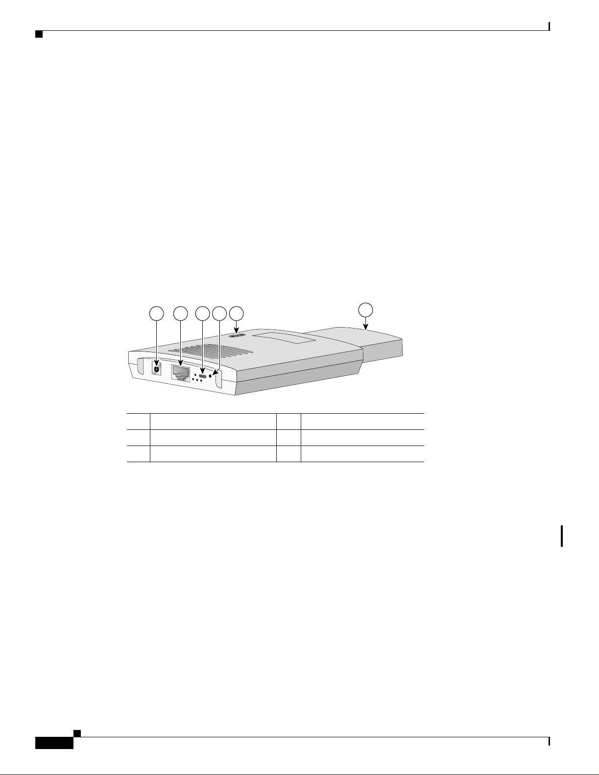
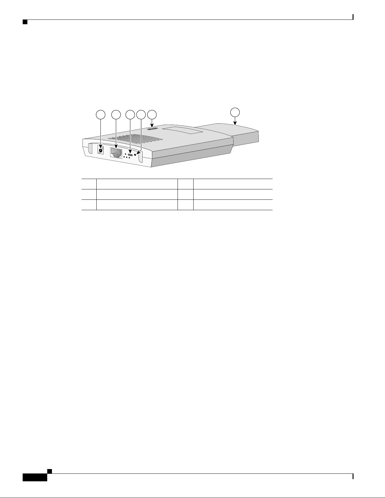
Figure 1-1 shows the location of some of the hardware features of the access point.
Figure 1-1 Access Point Layout and Connectors
Chapter 1 Overview
1 2 3 5
1 48-VDC power port 4 Mode button
2 Ethernet port (RJ- 45) 5 Status LEDs
3 Cable lock slot 6 Antenna
Single Radio Operation
The access point contains a 2.4-GHz radio in a mini-PCI slot and two 2.2-dBi dipole integrated antennas.
You can perform a field upgrade to the mini-PCI radio and antennas to support new radio technologies,
such as the 2.4-GHz IEEE 802.1 1g-co mpliant radio.
Ethernet Port
4
6
81180
1-2
The auto-sensing Ethernet port accepts an RJ-45 connector, linking the access point to your 10BASE-T
or 100BASE-T Ethernet L AN. T he a cce ss p oint ca n rece ive power through t he E the rne t c abl e fr om a
power injector, switch, or power patch panel. The Ethernet MAC address is printed on the label on the
back of the ac cess poin t.
Cisco Aironet 1100 Series Access Point Hardware Installation Guide
OL-4309-02
Page 19
Chapter 1 Overview
LEDs
Hardware Features
First Draft - CISCO CONFIDENTIAL
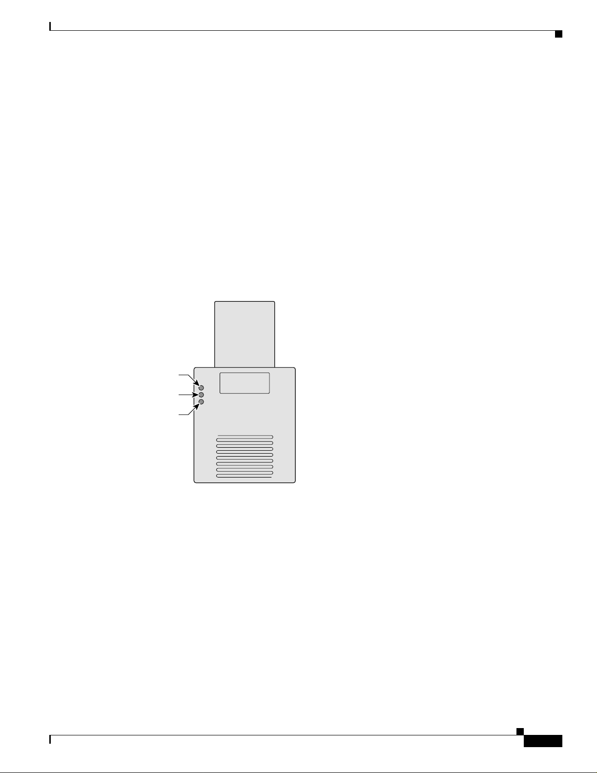
The three LEDs on the top of the access point re port Eth ernet activity, association status, and radio
activity.
• The Ethernet LE D sig na ls Et hern et tra ffic on the wire d L AN , or Ethe rn et i nfra str uc ture . Thi s L ED
is normally green when an Ethernet cable is connected, and blinks green when a packet is received
or transmitted over the Ethernet infrastructure. The LED is off when the Ethernet cable is not
connected.
• The status LED signals operational status. Steady green indicates that the access point is associated
with at least one wireless client. Bli nking green in dicates that th e access point is o perating normally
but is not associated with any wireless devices.
• The radio LED signals wirel ess traf fic o ver the r adio interf ace. The lig ht is normally o ff, b ut it blink s
green whenever a packet is received or transmitted over the access point radio.
Figure 1-2 shows the three status L EDs.
Figure 1-2 Access Point LEDs
Ethernet
Power Sources
The access point draws up to 4.9W of DC power and can receive power from an external power module
or through inlin e power using the Ethernet cable. Using inline power, you do not need to run a separ at e
power cord to the access point. The access poi nt supports the following power sources:
Status
Radio
81597
• Power supply (input 100–240 VAC, 50–60 Hz, output 48 V DC , 0. 2A m i nimu m)
• Inline power from:
–
Cisco Aironet Power Inje ctor for 11 00 an d 1200 se rie s ac cess point s
–
A switch capable of providing inline power, such as the Cisco Catalyst 3500XL, 3550, 4000, or
6500
OL-4309-02
–
An inline power patch pa nel, s uch a s t he Ci sco C ata lyst Inl ine Power Patch Pa nel
Cisco Aironet 1100 Series Access Point Hardware Installation Guide
1-3
Page 20

Hardware Features
First Draft - CISCO CONFIDENTIAL
UL 2043 Certification
The access point is encased in a durable plastic enclosure having adequate fire resistance and low
smoke-producing characteristics suitable for operation in a building's environmental air space, such as
above suspended ceilin gs, in acco rda nce w ith Se c tion 3 00- 22( c) o f the N EC, a nd wi th Se ct ions 2-1 28,
12-010(3) and 12 -100 of the Ca nadia n E lec trica l Co de , Part 1, C22.1.
Caution Cisco Aironet 1100 series power i nject ors and the un iversal power supplie s are n ot te sted to U L 204 3
and should not be plac ed i n a build ing ’s air-handling spaces, such as above suspended ceilings.
Anti-Theft Features
There are two methods of securing the acce ss point to help prevent theft:
• Security cable keyhole—You can use the securi ty cable sl ot to secure the access point usi ng a
standard securit y ca ble, su ch a s t hose used on lap top co mpu ter s.
• Security hasp—When you mount the acc ess po i nt o n a wall o r ce ilin g u sin g th e mo unting br ac ket
and the security hasp, you can lock the access point to the bracket with a padlock. Compatible
padlocks are Master Lo ck model s 120T and 121 T or equivalent.
Chapter 1 Overview
1-4
Cisco Aironet 1100 Series Access Point Hardware Installation Guide
OL-4309-02
Page 21
Chapter 1 Overview
First Draft - CISCO CONFIDENTIAL
Network Configuration Examples
This section describes the access point ’s role in three commo n wireless networ k configurati ons. The
access point’s default configuration is as a root unit connected to a wired LAN or as the central unit in
an all-wireless netwo rk. T he rep eat er r ol e r equ ire s a sp ec ific co nfigura tion.
Root Unit on a Wired LAN
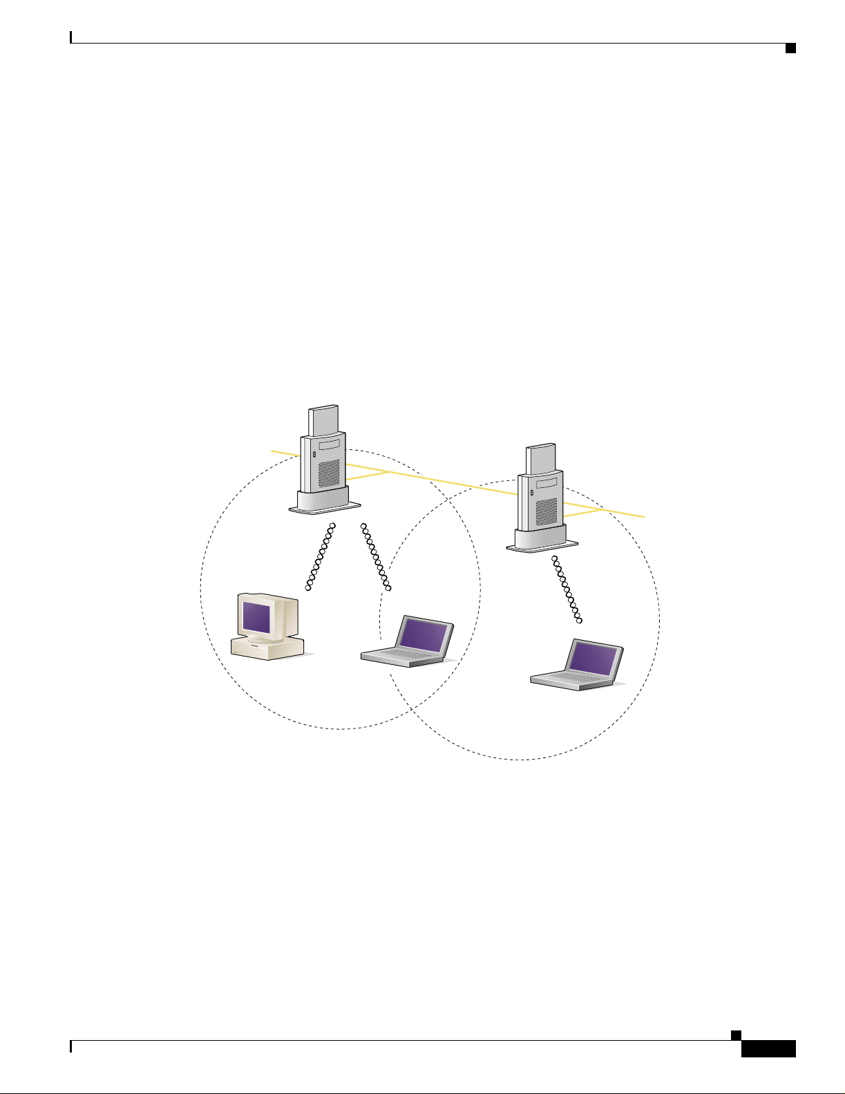
An access point connected directly to a wired LAN provides a connection point for wireless users. If
more than one access poi nt is connected to the LAN, users c an roam from one area of a fac ility to another
without losing thei r conn ect ion to t he ne twork. A s users move out o f range o f one a ccess poi nt, they
automatically con nect to the network (assoc iate) th rough anot her acces s point . The roami ng proce ss is
seamless and transparent to th e user. Figu re 1 -3 shows access poin ts acting as ro ot unit s on a wir ed LAN.
Figure 1-3 Access Points as Root Units on a Wired LAN
Access Point
(Root Unit)
Network Configuration Examples
Wired LAN
81173
Access Point
(Root Unit)
81173
86301
OL-4309-02
Cisco Aironet 1100 Series Access Point Hardware Installation Guide
1-5
Page 22
Network Configuration Ex am ples
First Draft - CISCO CONFIDENTIAL
Repeater Unit that Extends Wireless Range
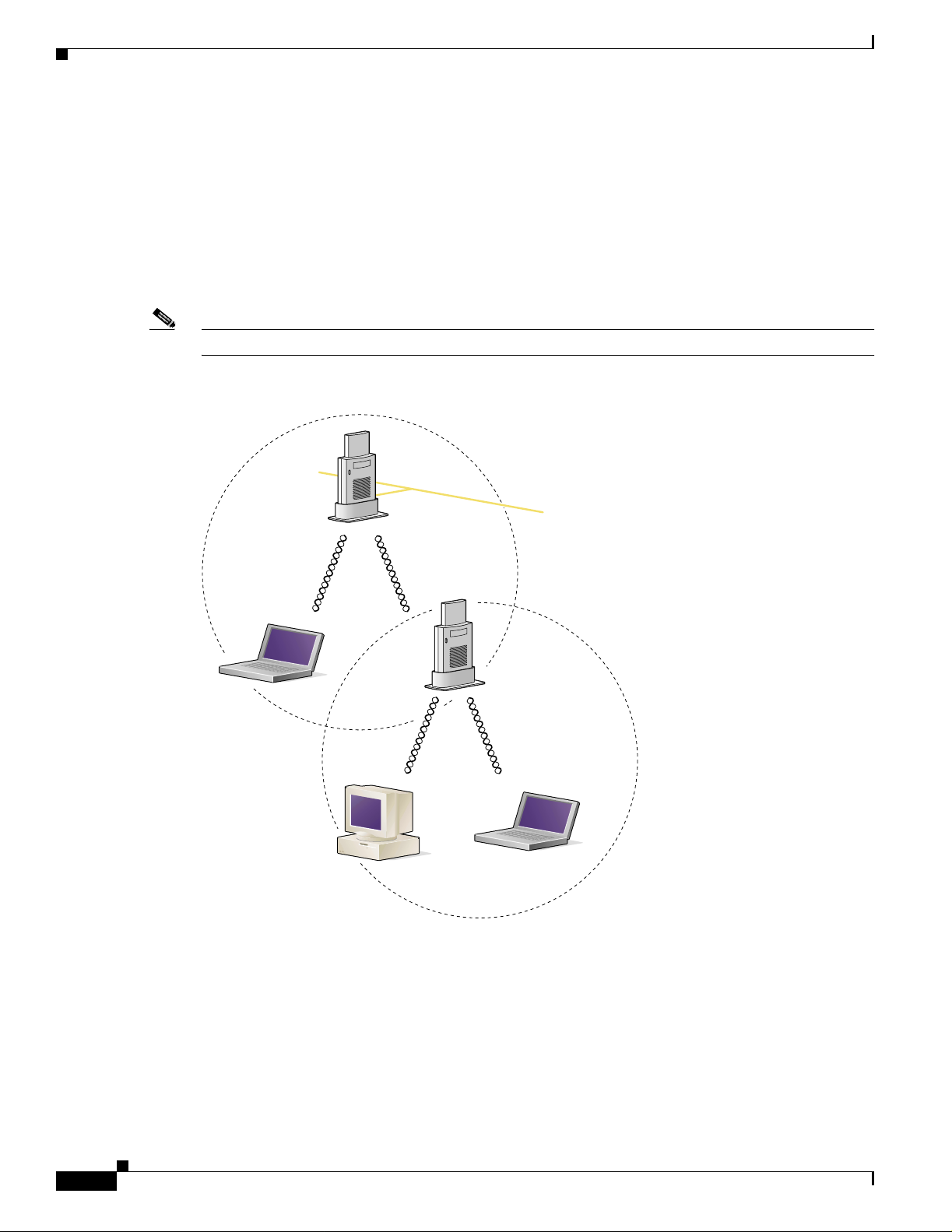
An access point can be configured as a stand-alone repeater to extend the range of your infrastructure or
to overcome an obstacle that blocks radio communication. The repeater forwards traffic between
wireless users and the wired LAN by sending packets to ei ther an other repe ater or to an a ccess poi nt
connected to the wired LAN. The data is sent through the route that provides the best performance for
the client. Figure 1-4 shows an access point acting as a repeater. Consult the Cisco IOS Software
Configuration Guide for Cisco Aironet Access Points for instructions on setting up an access point as a
repeater.
Note Non-Cisco client devices mi ght have difficulty communi cati ng wit h r epeat er a c cess points.
Figure 1-4 Access Point as Repeater
Chapter 1 Overview
Access Point
(Root Unit)
81173
Wired LAN
Access Point
81173
(Repeater)
86302
1-6
Cisco Aironet 1100 Series Access Point Hardware Installation Guide
OL-4309-02
Page 23
Chapter 1 Overview
First Draft - CISCO CONFIDENTIAL
Central Unit in an All-Wireless Network
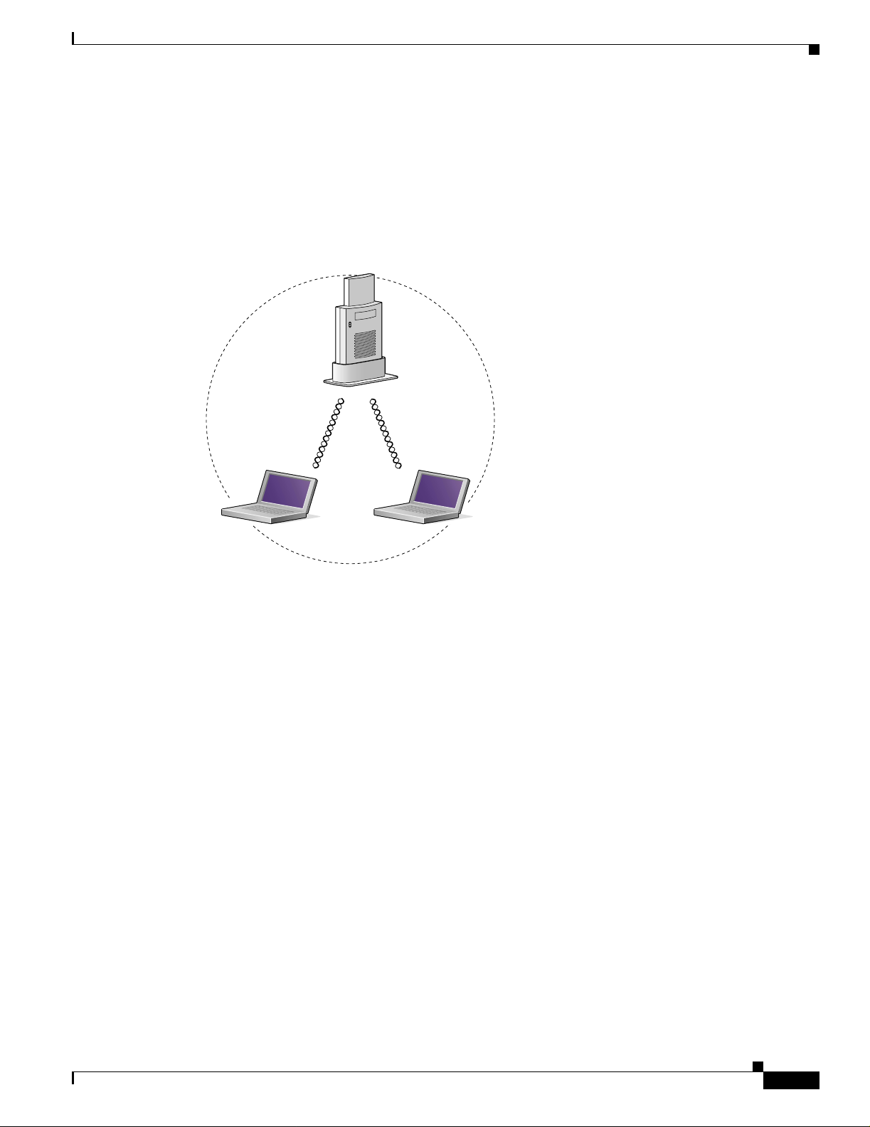
In an all-wireless network, an access point acts as a stand-alone root unit. The access point is not
attached to a wired LAN; it functions as a hub linking all stations together. The access point serves as
the focal point for communications, increasing the communication range of wireless users. Figure 1-5
shows an access point in an all-wireless network.
Figure 1-5 Access Point as Central Unit in All-Wireless Network
Access Point
(Root Unit)
81173
Network Configuration Examples
86300
OL-4309-02
Cisco Aironet 1100 Series Access Point Hardware Installation Guide
1-7
Page 24

Network Configuration Ex am ples
Chapter 1 Overview
First Draft - CISCO CONFIDENTIAL
1-8
Cisco Aironet 1100 Series Access Point Hardware Installation Guide
OL-4309-02
Page 25

First Draft - CISCO CONFIDENTIAL
CHAPTER
Installing the Access Point
This chapter describes the setup of the access point and includes the following sections:
• Safety Informat ion, p ag e 2-2
• Warnings, page 2-2
• Basic Installation Guidelines, page 2-3
• Unpacking the Access Po int, page 2-3
• Before Beginning the I nsta llat ion, pag e 2-4
• Installation Summary, page 2-4
• Connecting the Ethernet and Power Cables, page 2-5
2
OL-4309-02
Cisco Aironet 1100 Series Access Point Hardware Installation Guide
2-1
Page 26

Safety Information
First Draft - CISCO CONFIDENTIAL
Safety Information
Follow the guidelines in this section to ensure proper operation and safe use of the access point.
FCC Safety Compliance Statement
The FCC with its action in ET Docket 96-8 has adop ted a safet y standar d for human exposur e to radio
frequency (RF) electromagnetic energy emitted by FCC certified equipment. When used with approved
Cisco Aironet antennas, Ci sco Airo net product s meet th e uncontrol led environmental limits found i n
OET-65 and ANSI C95.1, 1991 . Proper installat ion of this ra dio acc ording to the instruc tions fou nd in
this manual will result in user exposure that is substantially below the FCC recommended limits.
General Safety Guidelines
• Do not touch or move antenna(s) while the unit is transmitting or receiving.
• Do not hold any c ompone nt co nt ain in g a ra di o so t h at the an t enn a i s ver y cl ose to or tou ch ing any
exposed parts of the body, especially the face or eyes, while transmitting.
• The use of wireless devices in hazardous locations is limited to the constraints posed by the local
codes, the nati onal c ode s, a nd the safe ty dire cto rs o f suc h environment s.
Chapter 2 Installing the Access Point
Warnings
Warning
Warning
Warning
Warning
Warning
Translated versions of the following safety warnings are provided in Appendix A , “Translated Safe ty
Warnings.”
In order to comply with FCC radio frequency (RF) exposure limits, dipole antennas should be located
at a minimum of 7.9 inches (20 cm) or more from the body of all persons.
Do not operate your wireless network device near unshielded blasting caps or in an explosive
environment unless the device has been modified to be especially qualified for such use.
Do not work on the system or connect or disconnect cables during periods of lightning activity.
Read the installation instructions before you connect the system to its power source.
This product relies on the building's installation for short-circuit (overcurrent) protection. Ensure that
a fuse or circuit breaker no larger than 120 VAC, 15A U.S. (240 VAC, 10A international) is used on the
phase conductors (all current-carrying conductors).
2-2
Cisco Aironet 1100 Series Access Point Hardware Installation Guide
OL-4309-02
Page 27

Chapter 2 Installing the Access Point
First Draft - CISCO CONFIDENTIAL
Unpacking the Access Point
Follow these steps to unpack the access point:
Step 1 Open the shipping container and carefully remove the contents.
Step 2 Return all pack ing ma ter ials to t he sh ippi ng c onta ine r and save it.
Step 3 Ensure that all items listed in the “Package Contents” sect ion are included in the s h ipment. Check each
item for damage. If any item is damage d or missin g, notif y your autho rized Cisc o sales repre sentat ive.
Package Contents
Each access point pack age co ntain s the foll owing items:
• Access point power pack
• Wall or ceiling m oun tin g b racke t
Unpacking the Access Point
• Security hasp adapter
• Cubical partition mounting bracket assembly
• Horizontal surface mo unting ho ls ter
• Mounting hardware ki t
• Product registration card
Basic Installation Guidelines
Because the access point is a radio device, it is susceptible to common causes of interference that can
reduce throughpu t a nd ra nge . Foll ow these b asic gu ide lin es t o ensu re the b es t pos sibl e perfo rm an ce:
• Install the acces s po int i n an a rea wher e lar g e st eel st ructu res s uch a s sh elving units , boo kcase s, an d
filing cabinets do not block the radio sign als to and from the access point.
• Install the access point away from microwave ovens. Microwave ovens operate on the same
frequency as the access point and can ca use signa l interfe rence .
OL-4309-02
Cisco Aironet 1100 Series Access Point Hardware Installation Guide
2-3
Page 28
Before Beginning the Installation
First Draft - CISCO CONFIDENTIAL
Before Beginning the Installation
Before you begin the i nsta llati on proc ess, p l ease refe r t o Figure 2-1 to familiarize yourself with the
access point’s layout, feature s, and co nnec tors.
Figure 2-1 Access Point Layout and Connectors
Chapter 2 Installing the Access Point
1 2 3 5
1 48-VDC power port 4 Mode button
2 Ethernet port (RJ- 45) 5 Status LEDs
3 Cable lock slot 6 Antenna
Installation Summary
During the installati on of the ac cess poin t, you need to perform the following oper ations :
• Connect Ethern et an d power cables (ref er to the “Con necting t he Etherne t and Power Cables”
section on page 2-5).
• Configure basic settings (refer to Chapter 3, “Configuring the Access Point for the First Time”).
• Configure security and other access poin t options.
4
6
81180
2-4
• Use the mounting brackets or docking cradle to locate the access point on a convenient flat
horizontal or vertical surface, such as a desktop, book shelf, file cabinet, cubicle wall, room wall, or
the room ceiling. For additional information, refer to Chapter 6, “Mounting Instructions.”
Cisco Aironet 1100 Series Access Point Hardware Installation Guide
OL-4309-02
Page 29
Chapter 2 Installing the Access Point
First Draft - CISCO CONFIDENTIAL
Connecting the Ethernet and Power Cab les
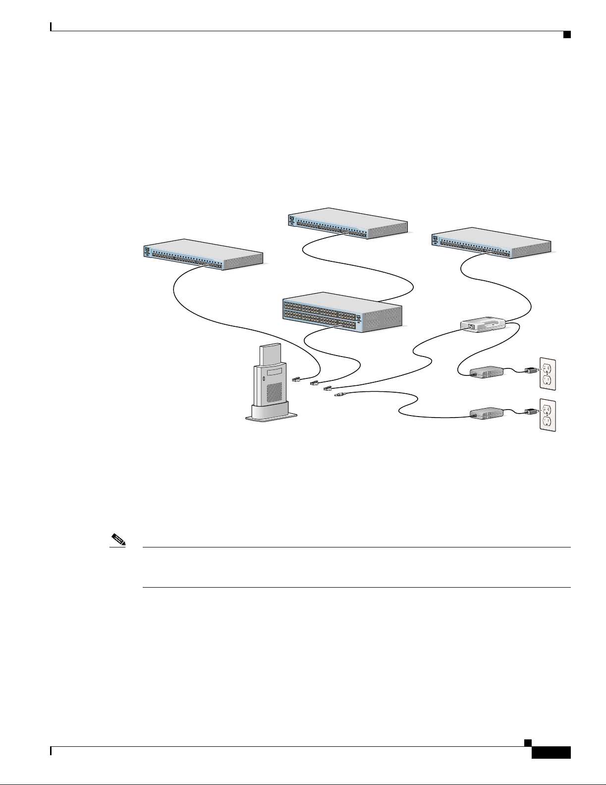
The access point receives power through the Ethernet cable or an external power module. Figure 2-2
shows the power options for the access point.
Figure 2-2 Access Point Power Options
Option 1 Option 2 Option 3
Switch
(without inline power)
SYS
T
1
RP
S
2
3
4
S
T
A
T
5
UT
IL
D
UP
LX
6
SPE
E
D
7
8
10Base-T / 100Base-TX
9
MO
Switch with
DE
inline power
SYST
1
RP
S
2
3
4
S
TAT
5
UTI
L
DU
P
LX
6
SPEE
D
7
8
10Base-T / 100Base-TX
9
MODE
10
11
12
13
14
15
16
17
18
Catalyst 2950
19
S
E
RI
20
E
S
21
22
100Base-FX
23
24
23
24
10
11
12
13
14
15
16
17
18
19
20
21
Inline Power
Patch Panel
Catalyst 2950
SERI
E
S
22
100Base-FX
23
24
23
24
Connecting the Ethernet and Power Cables
Switch
(without inline power)
S
Y
ST
1
RP
S
2
3
4
STA
T
5
UTIL
DUPLX
6
SP
E
E
D
7
8
10Base-T / 100Base-TX
9
M
ODE
10
11
12
13
14
15
16
17
18
Catalyst 2950
19
SE
RIE
20
S
21
22
100Base-FX
23
24
23
24
SYS
T
RPS
STA
T
UTIL
DUPLX
SPEED
MODE
Power injector
TO
AP/ BRIDGE
NETWORK
TO
Power
cord
Universal
power supply
81173
Access Point
Option 4
The access point power options are listed below:
• A switch with inlin e power, such as a Ci sco Ca ta lyst 35 00X L, 355 0, 4000, or 6 500 sw it ch
• An inline power patch pa nel, s uch a s a Ci sco Catal yst In line Power Patch Panel
• A power injector
• A power module (Universal power supply)
Note If you use in-line power from a switch or pat ch panel, do no t connect the power module to the ac cess
point. Using two power sources on the access point might cause the switch or patch panel to shut down
the port to which the access point is connected.
81596
OL-4309-02
Cisco Aironet 1100 Series Access Point Hardware Installation Guide
2-5
Page 30

Chapter 2 Installing the Access Point
Connecting the Ethernet and Power Cables
First Draft - CISCO CONFIDENTIAL
Connecting to an Ethernet Network with an Inline Power Source
Follow these steps to connect the access point to the Ethernet LAN when you have an inline power
source:
Step 1 Connect the Ethernet cable to the RJ-45 Ethernet connector labeled Ethernet on the access point.
Step 2 Connect the other en d of the Etherne t cable to one of the fol lowing:
• A switch with inlin e power, such as a Ci sco Ca ta lyst 35 00X L, 355 0, 4000, or 6 500 sw it ch.
• An inline power switch panel, such as a Cisco Catalyst Inline Power Patch Panel.
• The end of a Cisco Airo net p ower injec tor l abe led To AP/Bridge. Co nnect the othe r end l abe led To
Network to the 10/100 Ethernet LAN .
Caution The Cisco Aironet Power Injector for the 1100 and 1200 serie s is designed fo r use with 1100 serie s or
1200 series access points only. Using the power injector with other Eth erne t-re ady devices can dam age
the equipment.
Caution The Cisco Aironet Power Injector for the 1100 and 1200 series is not tested to UL 2043 and sh ould not
be placed in a building's environmental air space, such as above suspended ceilings.
Note If you use a power supply or power injector to power the access point , you must use the power suppl y
included with your access point and the Cisco Aironet Power Injector for the 1100 and 1200 series access
points.
Connecting to an Ethernet Network with Local Power
Follow these steps to connect the access point to an Ethernet LAN when you are using a local power
source:
Step 1 Connect the Ethernet cable to the RJ-45 Ethernet connector labeled Ethernet on the access point.
Step 2 Plug the othe r end of the Et hernet cab le into an un powered Ethernet port on your ne twork.
Step 3 Connect t he power modul e’s output co nnect o r to the 48- VDC power port label ed 48VD C on the access
point.
Step 4 Plug the othe r end of the power module into an approved 100- to 240- VAC outlet.
2-6
Cisco Aironet 1100 Series Access Point Hardware Installation Guide
OL-4309-02
Page 31

Chapter 2 Installing the Access Point
First Draft - CISCO CONFIDENTIAL
Powering Up the Access Poin t
When power is applied to t he a cce ss poin t, i t begins a rou tine p ower-up sequen ce tha t you ca n m onitor
by observing the three LED s on top of the access point. After you observe all three LEDs turning green
to indicate the starting of the IOS operating system, the Status LED blinks green signifying that IOS is
operational. When in an operational status, the Ethernet LED is steady green when no traffic is being
passed and dark during periods when traffic is being passed. The sequence takes about 1 minute to
complete. Refer to Chapter 8, “Troubleshooting,” for LED descri ptions .
When the sequence is complete, you are ready to obtain the access point’s IP address and pe rform a n
initial configuration. Refer to Chapter 3, “C onfiguring the A ccess Point for th e First Time,” for
instructions on assi gning basic set tings to t he a ccess point .
Connecting the Ethernet and Power Cables
OL-4309-02
Cisco Aironet 1100 Series Access Point Hardware Installation Guide
2-7
Page 32

Connecting the Ethernet and Power Cables
First Draft - CISCO CONFIDENTIAL
Chapter 2 Installing the Access Point
2-8
Cisco Aironet 1100 Series Access Point Hardware Installation Guide
OL-4309-02
Page 33

First Draft - CISCO CONFIDENTIAL
CHAPTER
3
Configuring the Access Point for the First Time
This chapter descri bes how to c onfigure ba sic set tings o n you r ac cess point for the first time . Th e
contents of this chapt er are simi lar to the i nstruct ions in th e quick star t guide t hat shipped with your
access point. You can configure all the settings described in this chapter using the CLI, but it might be
simplest to browse to the access point’s web-browser interface to complet e the initial co n figuration and
then use the CLI to enter additional settings for a more detailed configuration.
This chapter contains these sections:
• Before You Start, page 3-2
• Obtaining and Assigning an IP Address, page 3-3
• Connecting to the Access Point Locally, page 3-3
• Assigning Basic Settings , pa ge 3- 4
• Protecting Your Wireless LAN, page 3-8
• Using the IP Setup Utility, page 3-8
• Assigning an IP Address Using the CLI, page 3-11
• Using a Telnet Session to Access the CLI, page 3-11
OL-4309-02
Cisco Aironet 1100 Series Access Point Hardware Installation Guide
3-1
Page 34

Before You Start
First Draft - CISCO CONFIDENTIAL
Before You Start
Before you install the access point, make sure you are using a computer connected to the same networ k
as the access point, and obtain the following information:
• The following inform ati on from y our net work sy st em a dm ini stra tor:
–
–
–
–
–
• If you use IPSU to find or assign the access point IP address, the MAC address from the label on the
bottom of the acc ess po in t (s uch a s 0 016462 585 4c )
Chapter 3 Configuring the Access Point for the First Time
A system name
The case-sensitive wireless service set identifier (SSID) for your radio network
If not connected to a DH CP server, a unique IP add ress f or you r acc ess poi nt (su ch a s
172.17.255.115)
If the access poin t is not o n t he sa m e subne t a s yo ur PC, a defa ult gateway addr ess and su bne t
mask
A Simple Network Mana geme nt Pr otoc ol ( SNMP) com mun ity nam e an d the SNMP file
attribute (if SNMP is in use)
Resetting the Access Point to Default Settings
If you need to start over during the initial setup process, follow these steps to reset the access point to
factory default settings using the access point MODE button:
Step 1 Discon nect power (the power jack for extern al power or the Et herne t cable for i n-line power) from the
access point.
Step 2 Press and hold the MODE button while you reconnect power to the access point.
Step 3 Hold the MODE button until the Sta tus LED tur ns amber (a pproximately 1 to 2 second s), and rele ase the
button. All access point settings return to factory defaults.
You can also use the web-browser interface to reset the access point to defaults. Follow these steps to
return to default settings using the web-browser interface:
Step 1 Open your Internet browser. You must use Microsoft Internet Explorer (version 5.x or later) or Netscape
Navigator (version 4.x).
Step 2 Enter the access point’s IP address in the browser address line and press Enter. An Enter Network
Password window appears.
Step 3 Enter yo ur usern am e in t he U ser N ame field . T he d efa ult user nam e is Cisco.
Step 4 Enter the ac cess p oint pa ssword in the Password field and press Ente r. The default password is Cisco.
The Summary Status page app ears.
3-2
Step 5 Click System Software and the Sy stem S o ftwar e sc re en appe a rs.
Step 6 Click System Configuration and the System Configuration screen appears.
Step 7 Click the Default button.
Cisco Aironet 1100 Series Access Point Hardware Installation Guide
OL-4309-02
Page 35

Chapter 3 Configuring the A ccess Point for the First Time
First Draft - CISCO CONFIDENTIAL
Note If the access point is configured with a static IP address, the IP address will not be changed.
Obtaining and Assigning an IP Address
To browse to the access point’s Express Setup page, yo u must e ith er obt ain or as sig n the access point ’s
IP address using one of the following methods:
• Use default address 10.0 .0.1 w hen you co nnect to the a ccess point local ly. For detailed instructions,
see the “Connecting to the Access Point Locally” section on page 3-3.
• Use a DHCP server (if available) to automatically assign an IP address. You can find out the
DHCP-assigned IP address usi ng one of the following meth ods:
–
Provide your organization’s network administrator with your access point’s Media Access
Control (MAC) address. Your network administrator will query the DHCP server using the
MAC address to identify the IP address. The access point’s MA C address is on label attached to
the bottom of the access point.
Obtaining and Assigning an IP Address
–
Use the Cisco IP Setup Utility (IPSU) to identify the assigned address. You can also use IPSU
to assign an IP address to the access point if it did not receive an IP address from the DHCP
server. IPSU runs on most Microsoft Windows operating systems: Windows 9x, 2000, Me, NT,
and XP.
Yo u can download IPSU fro m the Software Center on Cisco.co m (For additiona l infor mation,
refer to the “Obtaining and Installing IPSU” section on page 3-8).
Connecting to the Access Point Locally
If you need to configure the access point locally (without connecting the access point to a wired LAN),
you can connect a PC to its Ethernet port using a Category 5 Ethernet cable. Yo u can use a local
connection to t he E the rne t p ort muc h as yo u would use a se ria l p ort co nne ctio n.
Note Yo u do not need a special cr ossover cable to conn ect your PC to the access point ; you can use
either a straight-thro ugh cable or a cr ossover cable.
If the access point is configured with default values and not connected to a DHCP server or cannot obtain
an IP address, it defaults to IP addr ess 10.0. 0.1 and bec omes a mini- DHCP server. In that capacity, the
access point pr ovides u p to tw en ty I P a dd resses be tw een 10. 0.0.1 1 a nd 1 0.0 .0. 30 to the fo llowing
devices:
• An Ethernet-capable PC connected to its Ethernet port
OL-4309-02
• Wireless client devices configured to use eithe r no SSID o r tsunam i as the SSID, and with all
security settings disabled
The mini-DHCP server featur e is disabled automatically when y ou assign a static IP address to the acc ess
point.
Cisco Aironet 1100 Series Access Point Hardware Installation Guide
3-3
Page 36

Assigning Basic Settings
Caution When an access point with default settings is connected on a wired LAN and does not receive an IP
Step 1 Make sure that the PC you intend t o use is conf igur ed to ob tain an IP ad dress auto matically, or manually
Step 2 Power up the access point.
Step 3 Follow the steps in the “Assigning Basic Settings” section on page 3-4. If you make a mistake and need
Step 4 After configuring the acc ess point, remo ve the Ethernet cable fro m your PC and conne ct the access point
Note When you connect your PC to the access point or reconnect your PC to the wired LAN, you might need
Chapter 3 Configuring the Access Point for the First Time
First Draft - CISCO CONFIDENTIAL
address from a DHCP server, the access point provides an IP address to any DHCP requests it receives.
Follow these steps to connect to the access point locally:
assign it an IP address from 10.0.0.2 to 10.0.0.10. Connect your PC to the access point using a Category
5 Ethernet cable. You can use either a crossover cable or a straight-through cable.
to start over , follo w the steps in the “Resetting the Access Point to Def ault Settings” secti on on pa ge 3-2.
to your wired LAN .
to release and renew the IP address on the PC. On mo st PCs, you can pe rform a re lease and re new by
rebooting your PC or by e nte ring ipconfig /release and ipconfig /renew commands in a command
prompt window. Consult your PC operating instructions for detailed instruction s.
Assigning Basic Settings
After you determine or assign the access point’s IP address, you can browse to the access point’s Express
Setup page and perform an initial configuration. Follow these steps:
Step 1 Open your Internet browser. You must use Microsoft Internet Explorer (version 5.x or later) or Netscape
Navigator (version 4.x).
Step 2 Enter the access point’s IP address in the browser address line and press Enter. An Enter Network
Password screen appears.
Step 3 Press Tab to bypass the Username field and ad vance to the Password field .
Step 4 Enter the case-sensitive password Cisco and press Enter. The Summary Status page appears. Figure 3-1
shows the Summary Status page.
3-4
Cisco Aironet 1100 Series Access Point Hardware Installation Guide
OL-4309-02
Page 37

Chapter 3 Configuring the A ccess Point for the First Time
First Draft - CISCO CONFIDENTIAL
Figure 3-1 Summary Status Page
Assigning Basic Settings
Step 5
Click Express Setup. The Express Setup screen appear s. Figure 3-2 shows the Express Setup pa ge.
Figure 3-2 Express Setup Page
OL-4309-02
Cisco Aironet 1100 Series Access Point Hardware Installation Guide
3-5
Page 38

Assigning Basic Settings
Step 6 Enter the configuration settings you obtained from your system administrator. The configurable settings
Chapter 3 Configuring the Access Point for the First Time
First Draft - CISCO CONFIDENTIAL
include:
• System Name— The system name, while not an essential setting, helps identify the access p oint on
your network. The system name appears in the titles of the management system pages.
• Configuration Server Protocol—Click on the button that matches the network’s method of IP
address assignme nt.
–
DHCP—IP addresses are automatically assigned by your network’s DHCP server.
–
Static IP—The access point uses a static IP address that you enter in the IP address field.
• IP Address—Use this setting to as sign or chan ge the access p oint’s IP address. If DHCP is enabled
for your network, leave thi s field bla nk.
Note If the access point’s IP address changes while you are configuring the access point using the
web-browser interface or a Telnet session over the wired LAN, you lose your connection t o the
access point. If you lose your connec tion, re connec t to the access point usin g its ne w IP addr ess.
Follow the steps in the “Resetting the Access Point to Default Settings” section o n pa ge 3-2 if
you need to start over.
• IP Subnet Mask—Enter the IP subne t m ask p rovided by you r ne twork admini str ator so the I P
address can be recognize d on the LAN. If DHCP is enabl ed, leave this field blank.
• Default Gateway—Enter the d efault gateway IP a ddress provided by your net work ad mini strat or.
If DHCP is enabled, leave this field blank.
• Radio Service Set ID (SSID)—Enter the case-sensitive SSID (32 alphanumeric characters
maximum) provided by your network administrator. The SSID is a unique identifier that client
devices use to associate with the access point.
• Broadcast SSID in Beacon —Use this setting to allow devices that do not specify an SSID to
associate with the access point.
–
Yes—This is the default setting; it allows devices that do not specify an SSID to associate with
the access point.
–
No—Devices must specify an SSID to associate with the access point. With No selected, the
SSID used by the client devices must match exactly the access point’s SSID.
• Role in Radio Network—Click on the button t hat desc ribe s th e role o f th e acc ess poi nt on y our
network. Select Access Point (Roo t) i f your acce ss point is conn ected to the wire d LAN. Sele ct
Repeater (Non-Roo t) if it is not connected to the wired LAN.
• Optimize Radio Network for—Use this setting to select either precon figured settings f or the access
point radio or customized set tings for th e access point radio .
–
Throughput—Maximizes the data volume handled by the access point but might reduce its
range.
–
Range—Maximize s the ac cess po int’s range but might red uce throu ghput.
3-6
–
Custom—The access poi nt uses se tt ings you enter o n th e Network I nte rfac es: Radio- 802 .11 b
Settings page. Clicking Custom takes you to the Network Interfaces: Radio-802.11b Settings
page.
• Aironet Extensions—Enable this setting if there are only Cisco Aironet devices on your wireless
LAN.
Cisco Aironet 1100 Series Access Point Hardware Installation Guide
OL-4309-02
Page 39

Chapter 3 Configuring the A ccess Point for the First Time
First Draft - CISCO CONFIDENTIAL
• SNMP Community—If your network is using SNMP , enter the SNMP Community name provided
by your network admini strat or and selec t t he a tt ributes of the SNM P da ta (al so provided by y our
network administr ato r).
Step 7 Click Apply to save your settings. If you changed the IP address, you lose your connection to the access
point. Browse to the new I P addr es s t o reco nne ct t o the ac cess po int .
Yo ur access poi nt is now running but probably requ ires additi onal con figuring to confo rm to your
network’s operational and secu rity require ments. Consult th e chapters in this manual for the inf ormation
you need to com pl ete th e co nfigurat ion.
Note Yo u can rest ore the acc ess point to its facto ry defaults by unplugging the power jack and
plugging it back in while holding down the Mode button for a few seconds, or until the Status
LED turns am be r.
Default Settings on the Express Setup Page
Assigning Basic Settings
Table 3-1 lists the default settings for the settings on the Express Setup page.
Table 3-1 Default Settings on the Express Setup Page
Setting Default
System Na me ap
Configuration Server Protocol DHCP
IP Address Assigned by DHCP by def ault; if
DHCP is disabled, the default
setting is 10.0.0.1
IP Subnet Mask Assigned by DHCP by def ault; if
DHCP is disabled, the default
setting is 255.255.255.224
Default Gateway Assigned by DHCP by def ault; if
DHCP is disabled, the default
setting is 0.0.0.0
Radio Service Set ID (SSID) tsunami
Broadcast SSID in Beacon Yes
1
Role in Radio Network Access point (root)
Optimize Radio N etwork fo r Throughput
Aironet Extensions Enable
SNMP Community defaultCommunity
1. When you assign multiple SSIDs, this setting no longer appears.
OL-4309-02
Cisco Aironet 1100 Series Access Point Hardware Installation Guide
3-7
Page 40

Protecting Your Wireless LAN
First Draft - CISCO CONFIDENTIAL
Protecting Your Wireless LAN
After you assign basic settings to your access point, you need to configure security settings to prevent
unauthorized access to your ne twork. Bec ause it is a radi o device, the access poi nt can comm unicat e
beyond the physical boundaries of your building. Refer to the Cisco IOS Software Configuration Guide
for Cisco Aironet Access P oints for information on how to conf igur e some com bination of these secu rity
features to protect y ou network from intrude rs:
• Unique SSIDs that are not broadcast in the access point beacon
• WEP and additional WE P f eat ures, su ch as T KIP an d b roadc ast key rotat ion
• Dynamic WEP and client authentication
Using the IP Setup Utility
IPSU enables you to find the access point’s IP address when it has been assigned by a DHCP server. You
can also use IPSU to set the access point’s IP addres s and SSID if they have not been changed from the
default settings.
Chapter 3 Configuring the Access Point for the First Time
Note IPSU can be used only on the following operating syste ms: Windows 95, 98, NT, 2000, ME, or XP.
Tip Another simple way to find the access point’s IP address is to look on the Status screen in the Aironet
Client Utility on a client device associated to the access point.
The sections below explain how to install the utility, how to use it to find the access point’s IP address,
and how to use it to set the IP address and the SSID.
Obtaining and Installing IPSU
IPSU is available on the Cisco web site. Follow these steps to obtain and install IPSU:
Step 1 Use your Internet browser to ac cess the Cisc o Softwa re Center at the following URL:
http://www.cisco.com/public/sw-center/sw-wireless.shtml
Step 2 Click Option 2: Aironet Wireless Software Display Tables.
Step 3 Locate the access point firmware and utilities section and click Cisco Aironet 1100 Series.
Step 4 Click IPSUvxxxxxx.exe. The vxxxxxx identifies the software package version number.
Step 5 On the Encryption Authorization Form, enter the requested information, read the encryption
information, and check the boxes that apply.
Step 6 Click Submit.
3-8
Step 7 Read and accept the terms and conditions of the Software License Agreement.
Step 8 Download and save the file to a temporary directory on your hard drive and then exit the Internet browser.
Step 9 Double-c li ck IPSU vxxxxxx .exe in the temporary directory to expand the file.
Cisco Aironet 1100 Series Access Point Hardware Installation Guide
OL-4309-02
Page 41

Chapter 3 Configuring the A ccess Point for the First Time
First Draft - CISCO CONFIDENTIAL
Step 10 Double-cl ick Setup.exe and follow the steps provided by the installation wizard to install IPSU.
The IPSU icon appears on your compu ter desktop .
Using IPSU to Find the Access Point’s IP Address
If your access point rece i v es an IP addr ess fr om a DH CP serv er, you can use IPSU to f ind its IP addre ss.
Because IPSU sends a reverse-ARP request based on the access point MAC address, you must run IPSU
from a computer on the same subnet as the access point. Follow these steps to find the access point’s IP
address:
Step 1 Double-click the IPSU icon on your comput er deskto p to st art the ut ility. The IPSU screen appears (see
Figure 3-3).
Figure 3-3 IPSU Get IP Address Scr een
Using the IP Setup Utility
OL-4309-02
Step 2
Step 3 Enter the access point’s MAC address in the Device MAC ID field. The access point’s MAC address is
When the utility window opens, make sure the Get IP addr radio button in the Function box is selected.
printed on the la bel on the bot tom of the uni t. It sh ould c onta in six pa irs of hexade cim al d igi ts. Your
access point’s MAC address might look like the following example:
000164xxxxxx
Note The MAC address field is not case-sensitive.
Step 4 Click Get IP Address.
Step 5 When the access point’s IP address appears in the IP Address field, write it down.
If IPSU reports that the IP address is 10.0.0.1, the default IP address, then the access point did not receive
a DHCP-assigned IP address. To change the access point IP address from the default value using IPSU,
refer to the “Using IPSU to Set the Access Point’s IP Address and SSID” section on page 3 -10.
Cisco Aironet 1100 Series Access Point Hardware Installation Guide
3-9
Page 42

Chapter 3 Configuring the Access Point for the First Time
Using the IP Setup Utility
First Draft - CISCO CONFIDENTIAL
Using IPSU to Set the Access Point’s IP Address and SSID
If you want to chang e t he de fault IP a dd ress ( 10.0. 0.1) of the acc ess p oint, yo u ca n u se IPSU . You can
also set the access point’s SSID at the same time.
Note The computer you us e to ass ign an IP ad dress to the ac cess poin t mus t have an IP address i n the sam e
subnet as the ac cess p oint ( 10 .0.0. x).
Note IPSU can change the access point’s IP address and SSID only from their default settings. After the IP
address and SSID have been c hange d, I PSU cann ot c hang e the m aga in.
Follow these steps to assign an IP address and an SSID to the access po int:
Step 1 Double-click the IPSU icon on yo ur co mp ut er d esk top t o st art the utilit y.
Step 2 Click the Set Par amete rs radio button in the Functio n box (see Figure 3-4).
Step 3
Figure 3-4 IPSU Set Parameters Screen
Enter the access point’s MAC address in the Device MAC ID field. The access point’s MAC address is
printed on the la bel on the bot tom of the uni t. It sh ould c onta in six pa irs of hexade cim al d igi ts. Your
access point’s MAC address might look like this example:
004096xxxxxx
Note The MAC address field is not case-sensitive.
3-10
Step 4 Enter the IP addr es s yo u want to assign t o t he acc ess po int in the I P Addr es s field.
Step 5 Enter the SSID yo u want to assign to the acc ess point in the SSID field.
Note You cannot set the SSID without also setting the IP address. However , you can set the IP address
without setting the SSID.
Cisco Aironet 1100 Series Access Point Hardware Installation Guide
OL-4309-02
Page 43

Chapter 3 Configuring the A ccess Point for the First Time
First Draft - CISCO CONFIDENTIAL
Step 6 Click Set Parameters to change the access point’s IP address and SSID settings.
Step 7 Click Exit to exit IPSU.
Assigning an IP Address Using the CLI
When you connect the access point to the wired LAN, the access point links to the network using a bridge
virtual interface (BVI) that it creates automatically. Instead of tracking separate IP addresses for the
access point’s Ethernet and radio por ts, the net work uses the BVI.
When you assign an IP address to the access point using the CLI, you must assign the address to the BVI.
Beginning in privileged EXEC mo de , fol low these s te ps t o assign a n IP add re ss to the ac cess point’s
BVI:
Command Purpose
Step 1
Step 2
Step 3
configure terminal Enter global configurat ion m ode.
interface bvi1 Enter interface configuration mode for the BVI.
ip address address
mask
Assign an IP address and a ddress mask to th e BVI. T his step
automatically saves the running configuration to the startup
configuration.
Note You lose your connection to the access point when you
assign a new IP address to the BVI. If you need to
continue configuring the acc ess point, use the new IP
address to open another Telnet session to the access
point.
Assigning an IP Address Using the CLI
Using a Telnet Session to Access th e CLI
Follow these steps to browse to access the CLI using a Telnet session. These steps are for a PC running
Microsoft Windows with a Telnet terminal application. Check your PC opera ting instruc tions fo r
detailed instructio ns for yo ur op erat ing syste m.
Step 1 Select Start > Programs > Accessories > Telnet.
If Telnet is not listed in your Accessories menu, select Start > Run, type Telnet in the entry field, and
press Enter.
Step 2 When the Telnet window appears, click Connect and select Remote System.
Note In Windows 2000, the Telnet window does not contain drop- down me nus . To start the Telnet
session in Windows 2000, type open followed by the access point’s IP address.
Step 3 In the Host Name field, type the access point’s IP address and click Connect.
Cisco Aironet 1100 Series Access Point Hardware Installation Guide
OL-4309-02
3-11
Page 44

Using a Telnet Session to Access the CLI
First Draft - CISCO CONFIDENTIAL
Chapter 3 Configuring the Access Point for the First Time
3-12
Cisco Aironet 1100 Series Access Point Hardware Installation Guide
OL-4309-02
Page 45

First Draft - CISCO CONFIDENTIAL
CHAPTER
4
Using the Web-Browser Interface
This chapter describes the web-browser interface that you can use to configure the access point. It
contains these sections:
• Using the Web-Browser Interface for the First Time, page 4-2
• Using the Management Pages in the Web-Browser Interface, page 4-2
• Using Online Help, page 4-5
The web-browser inte rface con tai ns mana geme nt p ag es t hat yo u us e t o ch an ge acc ess po i nt se ttin gs,
upgrade firmware, and moni tor a nd configur e ot her w irele ss d evices o n th e netwo rk.
Note The access point web-bro wser interface is fully compatible wi th Microsoft Internet Explorer (v ersion
5.x or later) or Nets ca pe N avigator (version 4.x) .
OL-4309-02
Cisco Aironet 1100 Series Access Point Hardware Installation Guide
4-1
Page 46

Chapter4 Using the Web-Browser Interface
Using the Web-Browser Interface for the First Time
First Draft - CISCO CONFIDENTIAL
Using the Web-Browser Interface for the First Time
Use the access point’s IP address to browse to the ma nage ment sy stem . See the “Obtaining and
Assigning an IP Addre ss ” section on page 3-3 for instructions on assigning an IP address to the access
point.
Follow these steps to begin usi ng t he w eb-b rowser i nter face:
Step 1 Start the browser.
Step 2 Enter the access point’s IP address in the browser Location field (Netscape Communic ator) or Address
field (Internet Explorer ) and press Enter. The Summary Status page appea rs.
Using the Management Pages in the Web-Browser Interface
The system management pages use consistent techniques to present and save configuration information.
A navigation bar is on the le ft sid e of the p age, and c onfigura tion a c tion butt ons appe ar at th e bot tom .
Yo u use t he navigatio n bar t o b rowse to other m an agem ent pages, and yo u use the co nfigurat ion a ct ion
buttons to save or cancel changes to the configuration.
Note Changes are applied only when you click Apply. It’s important to remember that clicking your browser’s
Back button returns you to the previous page without saving any changes you have made. Clicking
Cancel cancels any changes you m ad e on t he pa ge a nd keeps you o n th at pag e.
Figure 4-1 shows the web- browser int erfac e ho me page .
4-2
Cisco Aironet 1100 Series Access Point Hardware Installation Guide
OL-4309-02
Page 47

Chapter 4 Using the Web-Browser Interface
First Draft - CISCO CONFIDENTIAL
Figure 4-1 Web-Browser Interface Home Page
Using the Management Pages in the Web-Browser Interface
Using Action Buttons
Table 4-1 lists the page links and button s t hat app ear on mo st ma nage ment pa ges.
Table 4-1 Common Buttons on Management Pages
Button/Link Description
Navigation Links
Home Displays access point status page with info rmation on t he numb er of radio
Express Setup Displays the Express Setup page that includes basic settings such as system
Network Map Displays a list of infrastructure devices on your wireless LAN.
Association Displays a list of all devices on your wireless LAN, listing their system names,
OL-4309-02
devices associated to the access point, the status of the Ethernet and radio
interfaces, and a list of recent access point activity.
name, IP addres s, an d SSID .
network roles, and parent -client re lationsh ips.
Cisco Aironet 1100 Series Access Point Hardware Installation Guide
4-3
Page 48

Using the Management Pages in the Web-Browser Interface
First Draft - CISCO CONFIDENTIAL
Table 4-1 Common Buttons on Management Pages (continued)
Button/Link Description
Network Interfaces Displays sta tus and statistics for the Ethernet and radi o interf aces a nd prov ides
links to configurat ion page s f or e ach int erfac e.
Security Displays a summary of security settings and provides links to security
configuration pages.
Services Displays status for several access point features and links to configuration
pages for Telnet/SSH, CDP, Domain Name Server, Filters, Proxy Mobile IP,
QoS, SNMP, SNTP, and VL ANs .
System Software Displays the version number of the firmware that the access point is ru nning
and provides links t o c onfigurat ion page s for up gr adin g a nd m an agin g
firmware.
Event Log Displays the access point event log and provides links to configuration pages
where you can select events to be included i n traps, set event severity levels,
and set notification me thod s.
Configuration Action But tons
Apply Saves changes made on the page and remains on t he page.
Refresh Updates status informat ion or statis tics displaye d on a page.
Cancel Di scards chang es to the pa ge and remain s on the page.
Back Discards any changes m a de t o th e page and re tur ns to the p revious page .
Chapter4 Using the Web-Browser Interface
4-4
Cisco Aironet 1100 Series Access Point Hardware Installation Guide
OL-4309-02
Page 49

Chapter 4 Using the Web-Browser Interface
First Draft - CISCO CONFIDENTIAL
Character Restrictions in Entry Fields
Because the 1100 series access point uses Cisco IOS software, there are certain characters that you
cannot use in the entry fields on the web-bro wser interf ace. Table 4-2 lists the prohibited charac ter s an d
the fields in which you cannot use them .
Table 4-2 Prohibited Characters for Web-Browser Interface Entry Fields
Entry Field Type Prohibited Characters
Password entry fields ?
“
$
[
+
All other entry fields ?
“
$
[
+
Using Online Help
Using Online Help
Click the help icon at the top of a ny page in t he we b-bro wser interf ace to displa y online help. Figure 4-2
shows the print and help icons.
Figure 4-2 Print and Help Icons
When a help page appea rs in a new browser window, use the Select a topic drop-down men u to di spla y
the help index or instructions for common configuration tasks, such as configuring VLANs.
You also cannot use these
three char acter s as th e
first characte r in an e ntr y
field:
!
#
;
OL-4309-02
Cisco Aironet 1100 Series Access Point Hardware Installation Guide
4-5
Page 50

Using Online Help
Chapter4 Using the Web-Browser Interface
First Draft - CISCO CONFIDENTIAL
4-6
Cisco Aironet 1100 Series Access Point Hardware Installation Guide
OL-4309-02
Page 51

First Draft - CISCO CONFIDENTIAL
CHAPTER
5
Using the Command-Line Interface
This chapter describes the IOS command-line interface (CLI) that you can use to configure your access
point. It contains t hese s ectio ns:
• IOS Command Modes, page 5-2
• Getting Help, page 5-3
• Abbreviating Commands, page 5- 3
• Using no and default Forms of Commands , page 5-3
• Understanding CLI Mess ages , pa ge 5-4
• Using Command History, page 5-4
• Using Editing Features, page 5-6
• Searching and Filtering Output of show and more Commands, page 5-8
• Accessing the CLI, page 5-8
OL-4309-02
Cisco Aironet 1100 Series Access Point Hardware Installation Guide
5-1
Page 52

IOS Command Modes
First Draft - CISCO CONFIDENTIAL
IOS Command Modes
The Cisco IOS user interface is divided into many different modes. The commands available to you
depend on which mode you are cu rrently in. Enter a question mark (?) at the system prompt to obtain a
list of commands available for each command mode.
When you start a session on the acc ess poin t, you begin in user mode, often c alled u ser EX EC mod e.
Only a limited subset of the commands are available in user EXEC mode. For example, most of the user
EXEC commands are one-time commands, such as show commands, which show the current
configuration statu s, an d cl e ar commands, which clear counters or interfaces. The user EXEC
commands are not s aved when the acce ss poi nt reboot s.
To have access to all commands, you must enter privileged EXEC mode. Normally, you must enter a
password to enter privileged EX EC mod e. From thi s m ode, yo u m ust en ter privileged EX EC m ode
before you can ente r the glo ba l co nfigurat ion m ode.
Using the configurat ion m odes ( gl ob al, i nte rface , an d l ine ), you ca n make c hang es to the ru nni ng
configuration. If you save the configuration, these commands are stored and used when the access point
reboots. To access the various configuration modes, you must sta rt at glo bal c onfigura tio n mode . Fro m
global configuration mo de, you can e nter inte rface con figuration mod e and line co nfigurati on mode.
Table 5-1 describes the main command modes, how to access each one, the prom pt you see in th at mode, and
how to exit the mode. The examples in the table use the host name ap.
Chapter 5 U sing the Com m and-Line Interface
Table 5-1 Command Mode Summary
Mode Access Meth od Prompt Exit Meth od About This Mode
User EXEC Begin a session with
your access point.
ap>
Enter logout or quit. Use this mode to
• Change terminal settings
• Perform basic tests
• Display system
information.
Privileged EXEC While in user EXEC
mode, enter the
enable command.
Global configuration While in privileged
EXEC mode, en ter
the configure
ap#
ap(config)#
Enter disable to exit. Use this mode to verify
commands. Use a password to
protect access to this mode.
To exit to privileged
EXEC mode, enter exit or
end, or press Ctrl-Z.
Use this mode to c onfigure
parameters that apply to the
entire acc ess p oin t.
command.
Interface
configuration
While in global
configuration mode,
enter the interface
command (with a
specific interface).
ap(config-if)#
To exit to global
configuration mode, enter
exit. To return to
privileged EXEC mode,
press Ctrl-Z or enter end.
Use this mode to c onfigure
parameters for the E therne t
interfaces.
5-2
Cisco Aironet 1100 Series Access Point Hardware Installation Guide
OL-4309-02
Page 53

Chapter 5 Using the Command-L ine Interface
First Draft - CISCO CONFIDENTIAL
Getting Help
You can enter a question mark (?) at the s y s tem pr om p t to d i sp lay a lis t of co mm an d s available for each
command mode. You can also obtain a list of associated keywords and arguments for any command, as
shown in Table 5-2.
Tabl e 5-2 Hel p Su mma ry
Command Purpose
help Obtain a brief descript ion of the help syst em in any comman d mode.
abbreviated-command-en try? Obtain a lis t of comma nds that begin wit h a partic ular cha racter st ring.
For example:
ap# di?
dir disable disconnect
abbreviated-command-en try<Tab> Complete a partial command name.
For example:
ap# sh conf<tab>
ap# show configuration
? List all comma nds available for a part ic ular c omma nd mo de.
For example:
ap> ?
command ? List the associated keywords for a command.
For example:
ap> show ?
command keyword ? List the associ ated a rguments for a keyword.
Getting Help
For example:
ap(config)# cdp holdtime ?
<10-255> Length of time (in sec) that receiver must keep this packet
Abbreviating Commands
You have to enter only enough characters for the access point to recognize the command as unique. This
example shows how to enter the show configuration privileged EXEC command:
ap# show conf
Using no and default Forms of Commands
Most configuration commands also have a no form. In general, use the no form to disa ble a featu re or
function or reverse the action of a command. For example, the no shutdown interface configuration
command reverses the shutdown of an interface. Use the command without the keyword no to re-enable
a disabled feature or to enable a featur e that is disabled by default.
OL-4309-02
Cisco Aironet 1100 Series Access Point Hardware Installation Guide
5-3
Page 54

Understanding CLI Mess ages
First Draft - CISCO CONFIDENTIAL
Configuration commands can also have a default form. The default form of a command returns the
command setting to its default. Most commands are disabled by default, so the default form is the same
as the no form. However , some c ommands are enable d by def ault and ha ve v ariables set to certain def ault
values. In thes e case s, th e default command enables the command and sets variables to their default
values.
Understanding CLI Messages
Table 5-3 lists some error messages t hat y ou migh t enc oun ter w hil e usi ng t he C LI to co nfigure you r
access point.
Table 5-3 Common CLI Error Messag e s
Error Message Meaning How to Get Help
% Ambiguous command:
"show con"
You did not enter enough characters
for your access point to recognize the
command.
Re-enter the command followed by a question mark (?)
with a space between the command and the question
mark.
Chapter 5 U sing the Com m and-Line Interface
% Incomplete command.
% Invalid input detected
at ‘^’ marker.
You did not enter all the keywords or
values required by this command.
You entered th e co mm an d
incorrectly. The caret (^) marks the
point of the error.
Using Command History
The IOS provides a history or reco rd of comma nds that you have entered. Th is featu re is particu larly
useful for recalling long or complex commands or entries, including access lists. You can customize the
command history fea ture to suit y our n eeds as desc ribe d in the se se c tions:
• Changing the Command History Buffer Size, page 5-5
• Recalling Commands, page 5-5
• Disabling the Comm and Histo ry Feat ure, pa ge 5-5
The possible keywords that y ou can en ter wi th the
command are displayed.
Re-enter the command followed by a question mark (?)
with a space between the command and the question
mark.
The possible keywords that y ou can en ter wi th the
command are displayed.
Enter a question mark (?) to display all the commands
that are available in this command mode.
The possible keywords that y ou can en ter wi th the
command are displayed.
5-4
Cisco Aironet 1100 Series Access Point Hardware Installation Guide
OL-4309-02
Page 55

Chapter 5 Using the Command-L ine Interface
First Draft - CISCO CONFIDENTIAL
Changing the Command History Buffer Size
By default, the access p oi nt r ecor ds ten c omm and lin es in i ts hist ory buffer. Beginning in privileged
EXEC mode, enter this command to change the number of command lines that the access point records
during the current terminal session:
ap# terminal history [size number-of-lines]
The range is from 0 to 256.
Beginning in line configur ati on mode , en ter thi s co mmand to c onfigure t he nu mb er of com ma nd l ine s
the access point records for all sessions on a particular line:
ap(config-line)# history [size number-of-lines]
The range is from 0 to 256.
Recalling Commands
To recall commands fro m the histor y buffer, perform one of the actions listed in Table 5-4:
Using Command History
Table 5-4 Recalling Commands
1
Action
Press Ctrl-P or the up arrow key. Recall commands in the history buffer, beginning with the most recen t com ma nd.
Press Ctrl-N or the down arrow key. Return to more recent command s in the histo ry buffer after recalling comma nds
show history While in privileged EXEC mode, list the last several commands that you just
1. The arrow keys function only on ANSI-compatible terminals such as VT100s.
Result
Repeat the key sequence to recall successively older commands.
with Ctrl-P or the up arrow key. Repeat the key sequence to recall succ essively
more recent comm ands .
entered. The nu mb er of c om ma nds th at a re di spla yed i s de term ine d by the se ttin g
of the terminal history global configuration com ma nd an d hi s tory line
configuration comm and.
Disabling the Command Hist or y Feat ure
The command history feature is automatically enabled.
To disable the feature during the current terminal session, enter the terminal no history privileged
EXEC command.
To disable command history for the line, enter the no history line configurati on comm and.
OL-4309-02
Cisco Aironet 1100 Series Access Point Hardware Installation Guide
5-5
Page 56

Using Editing Features
First Draft - CISCO CONFIDENTIAL
Using Editing Features
This section describes th e editin g featur es that can he lp you manip ulate the command line. It con tains
these sections:
• Enabling and Disabling Editing Features, page 5-6
• Editing Commands th rou gh Keystrokes, page 5 -6
• Editing Comman d Li nes t hat W rap, page 5 -7
Enabling and Disabling Editing Features
Although enhan ced ed iting m ode is au to mat ical ly e na ble d, you c a n disab le it.
To re-enable the enhanced editing mode for the current terminal session, enter this command in
privileged EXEC mode:
ap# terminal editing
To reconfigure a specific line to have enhanced editing mode, enter this command in line configuration
mode:
ap(config-line)# editing
Chapter 5 U sing the Com m and-Line Interface
To globally disable enhanced editing mode, enter this command in line configuration mode:
ap(config-line)# no editing
Editing Commands through Keystrokes
Table 5-5 shows the keystrokes that you need to edit command lines.
Table 5-5 Editing Commands through Keystrokes
Capability Keystroke
Move around the command line to
make changes or correc tions.
Recall commands from th e buffer a nd
paste them in the command lin e. Th e
access point provides a buffer with
the last ten items that you deleted.
Ctrl-B or the left arrow
key
Ctrl-F or the right arrow
key
Ctrl-A Move the cursor to t he b eginn ing of the com ma nd lin e.
Ctrl-E Move the cursor to the end of the command line.
Esc B Move the cursor back one word.
Esc F Move the cursor forward one word.
Ctrl-T Transpose the character to the left of the cursor with the
Ctrl-Y Recall the most recent entry in the buffer.
Esc Y Recall the next buffer entry.
1
Purpose
Move the cursor back one ch arac ter.
Move the cursor forward one character.
character located at the cursor.
The buffer contains only the last 10 items tha t you have
deleted or cut. If you press Esc Y more than ten times, you
cycle to the first buffer entry.
5-6
Cisco Aironet 1100 Series Access Point Hardware Installation Guide
OL-4309-02
Page 57

Chapter 5 Using the Command-L ine Interface
First Draft - CISCO CONFIDENTIAL
Table 5-5 Editing Commands through Keystrokes (continued)
Using Editing Features
Capability Keystroke
Delete entries if you make a mistake
or change your mind .
Delete or Backspace Erase the character to the left of the cursor.
Ctrl-D Delete the character at the cursor.
1
Ctrl-K Delete all characters from the cursor to the end of the
Ctrl-U or Ctrl-X Delete all characters from the cursor to the beginning of
Ctrl-W Delete the word to the left of the cursor.
Esc D Delete from the cursor to the end of the word.
Capitalize or lowercase words or
capitalize a set of letters.
Esc C Capitalize at the cursor.
Esc L Change the word at the cursor to lowercase.
Esc U Capitalize letters from the cursor to the end of the word.
Designate a part ic ula r keystroke as
Ctrl-V or Esc Q
an executab le command, per haps as a
shortcut.
Scroll down a line or screen on
displays that are longer than the
terminal screen can display.
Note The More promp t app e ars for
Return Scroll down one line.
Space Scroll down one screen.
output that has more lines
than can be displ aye d o n th e
terminal screen, including
show command outp ut. You
can use the Return and
Space bar keystrokes
whenever you see the
More
prompt.
Redisplay the current command line
Ctrl-L or Ctrl-R Redisplay the current command line.
if the access point sudd en ly se nds a
message to your screen.
1. The arrow keys function only on ANSI-compatible terminals such as VT100s.
Purpose
command line.
the command lin e.
Editing Command Lines that Wrap
Yo u can use a wrapa round feature for commands t hat extend beyond a single line on the sc reen . When
the cursor reaches the right margin, the command line shifts ten spaces to the left. You cannot see the
first ten characters of the line, but you can scrol l back and ch eck the syntax at the beginning of the
command.
T o scroll back to the be ginning of the command entry, press Ctrl - B or the left arrow key repeatedly. You
can also press Ctrl-A to immediately m ove to t he begi nn ing o f th e l ine .
Note The arrow keys function only on ANSI-co mpati ble termi nals such as VT100 s.
OL-4309-02
Cisco Aironet 1100 Series Access Point Hardware Installation Guide
5-7
Page 58

Searching and Filtering Output of show and more Commands
First Draft - CISCO CONFIDENTIAL
In this example, the access-list global configuration command entry extends beyond one line. When the
cursor first reaches the en d of the line, the line is shifted ten spaces to the left and redisplaye d. The dollar
sign ($) sho ws t hat th e line has been scrol led to the left. Each time th e curs or reaches the end of the line,
the line is again shifted ten spaces to the left.
ap(config)# access-list 101 permit tcp 131.108.2.5 255.255.255.0 131.108.1
ap(config)# $ 101 permit tcp 131.108.2.5 255.255.255.0 131.108.1.20 255.25
ap(config)# $t tcp 131.108.2.5 255.255.255.0 131.108.1.20 255.255.255.0 eq
ap(config)# $108.2.5 255.255.255.0 131.108.1.20 255.255.255.0 eq 45
After you complete the entry, press Ctrl-A to check the complete synt ax before pressi ng the Return key
to execute t he co mm an d. Th e d o llar sig n ( $ ) ap pears at the end of the line to s how that the line has been
scrolled to the right:
ap(config)# access-list 101 permit tcp 131.108.2.5 255.255.255.0 131.108.1$
The software assumes you have a terminal screen that is 80 columns wide. If you have a width other than
that, use the terminal width privileged EXEC comm an d to se t t he wi dth of your t ermi n al.
Use line wrapping wit h the comm and hi story fea ture to rec all and modi fy previous comp lex command
entries. For info rmation a bout rec alling pr e vious command entries, see th e “Editing Commands through
Keystrokes” section on page 5-6.
Chapter 5 U sing the Com m and-Line Interface
Searching and Filtering Output of show and more Commands
You can search and filter the output for show and more commands. This is useful when you need to sort
through large amou nts o f outpu t or i f you want to exclu de ou tput th at y ou do no t ne ed t o see.
To use this functionality, enter a show or more command followed by the pipe character (|), one of the
keywords begin, include, or exclude, and an expression that you want to se arch f or or filter out:
command | {begin | include | exclude} regular-expression
Expressions are case sensitive. For example, if you enter | exclude output, the lines that contain output
are not displayed, but the lines tha t contain Output are displayed.
This example shows how to include in the output disp lay only line s where th e expression protocol
appears:
ap# show interfaces | include protocol
Vlan1 is up, line protocol is up
Vlan10 is up, line protocol is down
GigabitEthernet0/1 is up, line protocol is down
GigabitEthernet0/2 is up, line protocol is up
Accessing the CLI
Yo u can open th e access poi nt’s CLI using Telnet or Secure Shell (SSH).
Opening the CLI with Telnet
Follow these steps to open the CLI with Telnet. These steps are for a PC running Microsoft Windows
with a Telnet terminal application. Check your PC operating instructions for detailed instructions for
your operating system.
Cisco Aironet 1100 Series Access Point Hardware Installation Guide
5-8
OL-4309-02
Page 59

Chapter 5 Using the Command-L ine Interface
First Draft - CISCO CONFIDENTIAL
Step 1 Select Start > Programs > Accessories > Telnet.
If Telnet is not listed in your Accessories menu, select Start > Run, type Telnet in the entry field, and
press Enter.
Step 2 When the Telnet window appears, click Connect and select Remote System.
Note In Windows 2000, the Telnet window does not contain drop-down menus. To start the T elnet
session in Windows 2000, type open followed by the access point’s IP address.
Step 3 In the Host Name field, type the access point’s IP address and click Connect.
Step 4 At the us erna me a nd passwor d pro mpts, e nte r your a dmi nistra tor use rname an d p assword. The d efault
username is Cisco, and the default password is Cisco. The default enable password is also Cisco.
Usernames and passwor ds are c ase-sensi tive.
Opening the CLI with Secure Shell
Accessing the CLI
Secure Shell Protocol is a protocol that provides a secure, remote connection to networking devices set
up to use it. Secure Shell (SSH) is a so ft ware package that provid es secu re log i n s ess io ns by encrypting
the entire session. SSH features strong cryptographic authentication, strong encryption, and integrity
protection. For detailed information on SSH, visit the homepage of SSH Communications Security, Ltd.
at this URL:
http://www.ssh.com/
SSH provides more secu rity for remote connections than Telnet by providing strong encryption when a
device is authen ticated. See the Cisco IOS Softwar e Conf iguration Guide for Cisco Air onet Access Points
for detailed instructions on setting up the access point for SSH access.
OL-4309-02
Cisco Aironet 1100 Series Access Point Hardware Installation Guide
5-9
Page 60

Accessing the CLI
Chapter 5 U sing the Com m and-Line Interface
First Draft - CISCO CONFIDENTIAL
5-10
Cisco Aironet 1100 Series Access Point Hardware Installation Guide
OL-4309-02
Page 61

First Draft - CISCO CONFIDENTIAL
CHAPTER
6
Mounting Instructions
This appendix contains mou nting in structi ons for the ac cess po int and conta ins the foll owing topics:
• Overview, page 6-2
• Mounting on a Horizontal or Vertical Surface, page 6-3
• Mounting on a Suspende d Cei ling, page 6-4
• Using the S ecur ity Has p Ad apt er, page 6-6
• Mounting on a Cubical Wall Partition, page 6-7
• Using the Desktop Holster, page 6-8
• Using the Cable Lock Feature , page 6-9
OL-4309-02
Cisco Aironet 1100 Series Access Point Hardware Installation Guide
6-1
Page 62

Overview
Overview
Caution Cisco Aironet 1100 Series Power Injectors and the universal power supplies are not tested to UL 2043
Chapter6 Mounting Instructions
First Draft - CISCO CONFIDENTIAL
The mounting brac kets an d ha rdwar e ship ped w ith your ac cess p oi nt e nabl es you t o moun t it on any of
the following surfaces:
• Horizontal or vertical flat surfaces, such as walls or ceilings
• Suspended ceilings
• Cubical partition walls
• Desktop or other suitable hor izontal surface
The 1100 series access point provides adequate fire resistance and low smoke-producing characteristics
suitable for operation in a building's env ironmental air space, such as above suspended ceilings, in
accordance with Section 300-22(C) of the National Electrical Code (NEC) and Sections 2-128,
12-010(3) and 12 -100 of t he Ca nadi an E lec tri cal Cod e, Part 1 , C22.1.
and should not be plac ed i n a build ing ’s air-handling spaces, such as above suspended ceilings.
Security features for each of these mountin g methods are also provided. You can use a Kensington lock
(Notebook Microstar, model number 64068 ), which you must provide, t o make the access point mor e
secure when you mount it using any of the moun ting options.
You can use the security hasp ad a pte r pr ovided by Cisco to secure the access po in t with a padlock when
you use the wall or ceiling mount ing brac ket. The secu rity hasp adapte r provides maxim um physic al
security for your access poin t.
A mounting hardware kit is provided that contains the hardware and fasteners necessary to mount the
access point. Refer to Table 6-1 to identify the materials you need to mount your access point, then go
to the section conta ining the spe cific mounti ng proc edure.
Table 6-1 Mounting Material
Mounting Method Materials Required In Kit
Horizontal or vertical surface Wall or ceiling mounting bracket
Security hasp adapter
Four #8 x 1 in. (25. 4 mm ) s crews
Four wall anchors
3/16 in. (4.7 mm) or 3/32 in . (2.3 mm) dr ill bit
Drill
Suspended ceiling Wall or ceiling mounting bracket
Security hasp adapter
Two caddy fasteners with studs
Two plastic spacers
Two 1/4–20 Keps nuts
Standard screwdriver
Appropriate wrench or pliers
Yes
Yes
Yes
Yes
No
No
Yes
Yes
Yes
Yes
Yes
No
No
Office cubical wall partition Cubical partition mounting bracket assembly Yes
Desktop Desktop holster Yes
6-2
Cisco Aironet 1100 Series Access Point Hardware Installation Guide
OL-4309-02
Page 63

Chapter 6 Mounting Instruct ions
The wall or ceiling mounting bracket also serves as a template for transferring the location of the
bracket’s mounting holes to the mounting surface. Ref er to Figure 6-1 to locate the various mounting
holes for the m eth od you i nte nd to u se.
Figure 6-1 Mounting Bracket
1 Security hasp 3 Suspended ceiling mo unt holes
2 Access point mounting rail 4 Wall mount hol es
Mounting on a Horizontal or Vertical Surface
First Draft - CISCO CONFIDENTIAL
1 4 43 3 42
81171
Mounting on a Horizontal or Vertical Surface
Follow t hese s teps to mount the ac cess poi nt on a horiz onta l or v ertic al su rf ace, su ch as a ceil ing or w all.
Step 1 Use the wall or ceiling mounting bracket as a template to mark the locations of the mounting holes.
• Yo u can use any of the 10 h oles around th e periph ery (thr ee of wh ich are ident ified in the
illustration) of the bracket to moun t it using the supp lied #8 fasteners.
Step 2 Drill one of the following sized holes at the locations you marked:
• 3/16 in. (4.7 m m) if you are u sin g wall anc ho rs
• 3/32 in. (2.3 m m) if you are n ot u sin g wall a ncho rs
Step 3 Install the anchors into the wall if you are using them. Otherwise, go to Step 4.
Step 4 Secure the mounting bracket to the surface using the #8 fasteners.
Note On a vertical surface, be sure to moun t the bracket wi th its secu rity has p facing down.
Step 5 Line up the mounting slots on the access point with the mounting rail on the mounting bracket and slide
down the mounting rails until it clicks into place.
OL-4309-02
Cisco Aironet 1100 Series Access Point Hardware Installation Guide
6-3
Page 64

Mounting on a Suspended Ceiling
First Draft - CISCO CONFIDENTIAL
Mounting on a Suspended Ceiling
Follow these steps to mount your access point on a suspende d ceilin g. It may be hel pful to refe r to
Figure 6-2 before b eginning the pr oces s.
Figure 6-2 Suspended Ceiling Mounting Bracket Parts
2
3
Chapter6 Mounting Instructions
1
2
3
4
5
5
81190
1 Suspended ceiling T-rail 4 Wall or ceiling mounting bracket
2 Caddy fastener 5 Keps nut
3 Plastic spacer
Step 1 Determine the location at which to mount the access point.
Step 2 Attach two caddy fasteners to the ceiling’s T-rail.
Step 3 Use the wall or ceiling mounting bracket to adjust the distance between the caddy fasteners so that they
align with the holes in the bracket.
• The distance betwe en the ca ddy fastene r studs is 2.5 i n (6.35 cm).
Step 4 Use a standard screwdriver to tighten the caddy fastener studs in place on the T-rail. Do not overtighten.
Step 5 Install a plastic spacer on each caddy fastener stud. The spacer’s legs should contact the ceiling grid
T-rail.
6-4
Step 6 Attach the wall or ceiling mounting bracket to the caddy fastener studs and start a Keps nut on each stud.
Step 7 Use a wrench or pliers to tighte n the Keps nuts. Do not overtighte n.
Cisco Aironet 1100 Series Access Point Hardware Installation Guide
OL-4309-02
Page 65

Chapter 6 Mounting Instruct ions
Step 8 Line up the mounting slots on the access point with the mounting rail on the wall or ceiling mounting
bracket and slide it down the mounting rails until it clicks into place. See Figure 6-3.
Figure 6-3 Access Point Mounting Slots
Mounting on a Suspended Ceiling
First Draft - CISCO CONFIDENTIAL
81224
OL-4309-02
Cisco Aironet 1100 Series Access Point Hardware Installation Guide
6-5
Page 66

Using the Security Hasp Adapter
First Draft - CISCO CONFIDENTIAL
Using the Security Hasp Adapter
The security hasp on the wall or ceili ng mount ing bra cke t and th e secur ity hasp ad apter locks the access
point to the bracket to make it more secure. After you have installed the access point on the detachable
mounting bracket, follow these step s to secur e it with a padl ock (Maste r Lock mo del 120T, 121T or
equivalent).
Step 1 Connect the Ethernet cable and power jack.
Step 2 Insert the T-shaped tab on the security hasp adapter into the Kensington lock slot on the access point.
See Figure 6-4.
Figure 6-4 Security Hasp Adapter
Chapter6 Mounting Instructions
8117781176
Step 3
Rotate the adapter to engag e it with t he secur ity hasp. T he hole in the ada pter should be aligned with th e
hole in the security hasp.
Step 4 Secure the adapter to the security hasp with a padlock. Your installation will look similar to Figure 6-5.
Figure 6-5 Security Hasp with Padlock
6-6
Cisco Aironet 1100 Series Access Point Hardware Installation Guide
OL-4309-02
Page 67

Chapter 6 Mounting Instruct ions
First Draft - CISCO CONFIDENTIAL
Mounting on a Cubical Wall Partition
Follow these steps to mount the access point on a cubical wall partition.
Step 1 Select the place on the partition where you want to mount the access point.
Step 2 Determine the width of the partition yo u are going to mount the ac cess poin t on.
Step 3 Assemble the cubical partition mounting bracket by sliding the two pieces together. You can use either
the short or long part of the bracket to obtain the proper fit to the partition wall.
• The bracket is adjust able fro m 2.125 i n. (5.39 cm) to 4.25 in . (10.7 9 cm).
Step 4 Connect the Ethernet and power cables.
Step 5 Line up the mounting slots on the access point with the mounting rails on the cubical partition mounting
bracket and slide it down the rails until it clicks into place.
Step 6 Position the mounting bracket over the partition wall and adjust it to fit. See Figure 6-6.
Figure 6-6 Cubicle Wall Bracket
Mounting on a Cubical Wall Partition
OL-4309-02
81223
Cisco Aironet 1100 Series Access Point Hardware Installation Guide
6-7
Page 68

Using the Desktop Holster
First Draft - CISCO CONFIDENTIAL
Using the Desktop Holster
Follow these steps to mount the access point on a desktop or other horizontal surface using the supplied
desktop holster.
Step 1 Select a suitable location to place the holster.
Step 2 Connect the Ethernet and power cables.
• If you are going to secure the access point wit h a Kensington lock , attach it now.
Step 3 Position the holster so that its back side is facing you.
Step 4 Insert the access point into the holster while guiding th e cables so that the y do not inter fere with the sides
of the holster. You will hear a click when the access point locks into place. See Figure 6- 7.
Figure 6-7 Desktop Holster
Chapter6 Mounting Instructions
6-8
81173
76406
Cisco Aironet 1100 Series Access Point Hardware Installation Guide
OL-4309-02
Page 69

Chapter 6 Mounting Instruct ions
First Draft - CISCO CONFIDENTIAL
Using the Cable Lock Feature
When you mount the access point using the cubical partition mount or desktop holster, you can secure
the access point with your own security cable. Follow these steps to install the security cable.
Note Cisco recommends using a Kensington Notebook Microstar (model number 64068) to secure your access
point.
Step 1 Loop the security cabl e around a nearby immovable object.
Step 2 Insert the key into the lock.
Step 3 Insert the lock into the security slot on the access point.
Step 4 Rotate the key right or left to secure the lock to the access point.
Step 5 Remove t h e key.
A properly secured lock and cable look si milar to Figur e 6-8.
Using the Cable Lock Feature
Figure 6-8 Kensington Lock
81175
OL-4309-02
Cisco Aironet 1100 Series Access Point Hardware Installation Guide
6-9
Page 70

Using the Cable Lock Fe at ure
Chapter6 Mounting Instructions
First Draft - CISCO CONFIDENTIAL
6-10
Cisco Aironet 1100 Series Access Point Hardware Installation Guide
OL-4309-02
Page 71

First Draft - CISCO CONFIDENTIAL
CHAPTER
2.4 GHz Radio Upgrade
This chapter provid es upgra de instr uc tions for t he 2 .4- GHz ( IE EE 8 02. 11b -com pli ant or
IEEE 802.11g-com pl iant) r adio car d an d in clud es the fo llowing se ctio ns:
• Upgrade Overview, page 7-2
• Unpacking the Radio, p age 7-2
• Removing the Back Cover, page 7-3
• Removing a 2.4-GHz Radio, page 7-4
• Installing a 2.4-GHz Radio, page 7-5
• Replacing the B ack Cover, page 7-8
7
OL-4309-02
Cisco Aironet 1100 Series Access Point Hardware Installation Guide
7-1
Page 72

Upgrade Overview
First Draft - CISCO CONFIDENTIAL
Upgrade Overview
This section pr ovides in struc tions for u pgr adin g the a cces s po int 2. 4-GH z r ad io. Th e fo llowing
operations summarize th e upgrade pro cedu re:
1. Remove all cables and power connections from the access point.
2. Follow standard electrostatic discharge (ESD) procedures.
3. Place the access point on an ESD-protected work surface.
4. Remove t he ac c ess po in t ’s back c over.
5. Remove the existing 2.4-GHz radio card.
6. Install the new 2.4-GHz radio car d.
7. Replace the access point’s back cover.
8. Install the new compliance labels.
Caution ESD can damage the Cisco Aironet radio an d the interna l compone nts of the acc ess point. It is
recommended th at th e 2.4-G H z ra dio up gra de p roc edur es be p erfo rme d by an ES D-t rai ned se rv ice
technician at an ESD-protected workstation.
Chapter 7 2.4 GHz Radio Upgrade
Note After you install the new radio, all configurable radio settings will be at default values. Refer to the Cisco
IOS Software Configuration Guide for Cisco Aironet Access Points for complete instruc tions on
configuring the new radio.
Unpacking the Radio
Each 2.4-GHz (IEEE 802.11G) radio is shipped with the following items:
• Quick start guide
• A product registra tio n ca rd
• A T-10 tamper-resistant Torx L-wrench (not used on 1100 series acc ess point s)
• Two 1100 series ac cess point labe ls
• A 1200 series access point 2.4 -GH z ra dio c ompl ian ce la bel (not used on 110 0 serie s a ccess p oi nts)
If anything is missing or dam aged, con t act your Ci sco r epre se ntative for supp ort.
7-2
Cisco Aironet 1100 Series Access Point Hardware Installation Guide
OL-4309-02
Page 73

Chapter 7 2.4 GHz Radio Upgrade
First Draft - CISCO CONFIDENTIAL
Removing the Back Cover
To remove the acce ss point ’s back cover, follow these steps:
Step 1 Remove all cables and power connections from the access point.
Step 2 Remove all static-generating items from the work area, such as plastic material, styrofoam cups, and
other similar items.
Step 3 Place the access point and the new 2.4-GHz radio (in its antistatic bag) on an antistatic work surface.
Step 4 Discharge any st atic buildup o n y our b ody by touc hing a g rounde d surface ( antis tat ic work su rface )
before proceeding .
Step 5 Position the access point so that the back cover is facing up.
Caution The internal access point com pon en ts a nd the 2.4- GHz r adio ca n b e da mage d by ESD f rom im pro per
handling.
Step 6 Remove the back cover retaining screw using a philips screwdriver (see Figure 7-1).
Removing th e B ack Cover
Figure 7-1 Access Point Back Cover Screw
1 Back cover screw 2 Back cover
Step 7 Hold the fr ont cover with one hand and wit h the oth er hand gen tly slide the back cover towards the
connector end o f the un it.
Step 8 Gently lift the connector end of the back cover and remove the cover.
OL-4309-02
Go to the “Removing a 2.4-GHz Radi o” section.
Cisco Aironet 1100 Series Access Point Hardware Installation Guide
7-3
Page 74

Removing a 2.4-GHz Radio
First Draft - CISCO CONFIDENTIAL
Removing a 2.4-GHz Radio
To remove a 2.4-GH z ra dio ca rd f rom y our a cce ss p oint , fol low these steps :
Caution The internal access point com pon en ts a nd the 2.4- GHz r adio ca n b e da mage d by ESD f rom im pro per
handling.
Step 1 Gently lift the top of the antenna card until it clears the plus shaped (+) support post (see Figure 7 -2).
Figure 7-2 Radio Card and Antenna Card
Chapter 7 2.4 GHz Radio Upgrade
7-4
1 Support post 4 Radio Card
2 Antenna car d 5 Card-retaining clips
3 Support bracket 6 Mini-PCI connecto r
Step 2 Gently pull the antenna card to remove it from the notch in the support bracket. Do not disconnect the
antenna wire conn ect ors.
Step 3 Push the card-retaining clips (on each side of card) away from the radio card (see Figure 7-2). W he n
released, the radio card springs up. Do not disconnect the antenna wires.
Step 4 Remove the 2.4-GH z radio car d from the mi ni-P CI connec tor by performing the foll owing operations:
a. Grasp the radio ca rd only on th e edges, be ing care ful not to touch com ponent s on the board or the
gold connector pi ns.
b. Remove the 2.4-GHz card from the mini-PCI connector.
Step 5 Place the radio card and antenna card on the ESD-protected work surface.
Cisco Aironet 1100 Series Access Point Hardware Installation Guide
OL-4309-02
Page 75

Chapter 7 2.4 GHz Radio Upgrade
Step 6 Use y our finge rs to c ar eful ly r em ove the ant enna w ire conne c tors f rom the 2.4 -G Hz r adi o car d. D o n ot
remove the antenna w ire conn ec to rs from t he ant enn a boa rd .
Caution The antenna connectors can be damaged by using a pair of long-nose pliers during the removal
Caution To avoid damaging the ant enna wi re assemb l ies, hand l e them by t hei r conne cto rs.
Figure 7-3 Antenna Wires
Installing a 2.4-GHz Radio
First Draft - CISCO CONFIDENTIAL
process.
1 Antenna card 2 Radio card
Step 7
Place the removed 2.4-GHz radio card into an anti-static bag. The antenna card will be connected to your
new radio card.
Go to the “Installing a 2.4-G Hz Radio” section.
Installing a 2.4-GHz Radio
To install a new 2.4-GHz radio card into the access point, follow these steps:
Caution The internal access point com pon en ts a nd the 2.4- GHz r adio ca n b e da mage d by ESD f rom im pro per
handling.
Step 1 Carefull y remove the new Cisc o Air one t 2 .4- GHz r a dio ca rd from i ts a nti-st at ic bag.
Step 2 Grasp t he rad io ca rd on ly on t he edg es, b ein g care fu l not to tou ch com pon en ts on th e bo ar d or the gold
connector pins.
Step 3 Place the radio card on the anti-static work surface next to the antenna card.
OL-4309-02
Cisco Aironet 1100 Series Access Point Hardware Installation Guide
7-5
Page 76

Installing a 2.4-GHz Radio
Step 4 Use your fingers to carefully connect the antenna wire connectors to the connectors on the 2.4-GHz radio
Step 5 Insert the radio card into the access point’s mini-PCI connector by following these steps:
Chapter 7 2.4 GHz Radio Upgrade
First Draft - CISCO CONFIDENTIAL
card (see Figure 7-3).
Caution The antenna connectors ca n be damaged by using a pair of long-n ose pliers.
Caution To avoid damaging the ant enna wi re assemb l ies, hand l e them by t hei r conne cto rs.
a. Tilt the radio card at approximately 20
connector (see Figure 7-4).
Figure 7-4 Inserting Radio Card in Mini-PCI Connector
o
to 30o so that its gold pins are aligned with the mini-PCI
7-6
1 Ante nn a car d 3 Mini-PCI connect or
2 Radio card
Push the radio card into the mini-PCI connector until it clicks into place.
b.
Step 6 Hold the t op of the ante nna card and ca refu lly push the ra dio card down (towards the access poi nt’s
motherboard) until the card-retaining clips lock into the notches on the side of the radio card (you will
hear a click).
Cisco Aironet 1100 Series Access Point Hardware Installation Guide
OL-4309-02
Page 77

Chapter 7 2.4 GHz Radio Upgrade
Step 7 Insert the antenna card into the no tch in the supp ort brac ket and gently push until it is sea ted (see
Figure 7-5).
Figure 7-5 Inserting Antenna Card
Installing a 2.4-GHz Radio
First Draft - CISCO CONFIDENTIAL
1 Antenna c ard 2 Support bracket notch
Step 8
Align the hole on the top of the antenn a board with the support post and gen tly push down until the board
is fully seated on the support post.
Step 9 Carefull y position the antenna wires so that t he metal conn ectors do not touch eac h other.
Caution Damage to the radio could occur if the an tenna c onnect ors are touc hing whe n power is applied . If they
are touching, carefully rotate them in opposite directions until they are separated.
Go to the Replacing the Back Cover, page 7-8 section.
OL-4309-02
Cisco Aironet 1100 Series Access Point Hardware Installation Guide
7-7
Page 78

Replacing the Back Cover
First Draft - CISCO CONFIDENTIAL
Replacing the Back Cover
To replace the back cover on the access point, follow these steps:
Step 1 While holding the back cover near the connector end, carefully place the antenna end’s latches into the
detents on the antenna end of the front cover (refer to Figure 7-6).
Figure 7-6 Positioning the Back Cover Latches
Chapter 7 2.4 GHz Radio Upgrade
1 Bac k cove r 3 Detent
2 Latch 4 Front cove r
Step 2
Release the back co ver and with one fi ng er ge ntly push the connector end o f th e back cover tow ar ds th e
antenna end. The back cover drops into place and slides forward until it is fully seated.
Step 3 Use a phil ips screwdriver to hand tighten th e cover’s retaining screw.
Step 4 Remove the backing paper from each 1100 series access point compliance label and carefully place the
label over the existing label (see Figure 7-7).
Figure 7-7 Location of Compliance Labels
7-8
1 2.4-GHz radio label 2 Product complia nce label
3 Back cove r
Cisco Aironet 1100 Series Access Point Hardware Installation Guide
OL-4309-02
Page 79

Chapter 7 2.4 GHz Radio Upgrade
The radio card installation is no w c omplete . To configure the new radio wi th your ne w wi reless n etwork
settings, refer to the Ci sco IOS So ftware Configuration Guid e for C isco Aironet Access Points.
Replacing the Back Cover
First Draft - CISCO CONFIDENTIAL
OL-4309-02
Cisco Aironet 1100 Series Access Point Hardware Installation Guide
7-9
Page 80

Replacing the Back Cover
Chapter 7 2.4 GHz Radio Upgrade
First Draft - CISCO CONFIDENTIAL
7-10
Cisco Aironet 1100 Series Access Point Hardware Installation Guide
OL-4309-02
Page 81

First Draft - CISCO CONFIDENTIAL
CHAPTER
8
Troubleshooting
This chapter provides troubleshooting procedures for basic problems with the access point. For the most
up-to-date, detailed troubleshooting information, refer to the Cisco TAC website at the following URL
(select Hardware Support > Wireless Devices):
http://www.cisco.com/tac
Sections in this chapter include:
• Checking the Top Panel LEDs, page 8-2
• Checking Basic Settings , page 8-4
• Resetting to the Default Configurat ion, pag e 8-4
• Reloading the Access Point Image, page 8- 6
• Obtaining the Access Point Image File, page 8-8
• Obtaining the TFTP Server Software, page 8-8
OL-4309-02
Cisco Aironet 1100 Series Access Point Hardware Installation Guide
8-1
Page 82

Checking the Top Panel LEDs
First Draft - CISCO CONFIDENTIAL
Checking the Top Panel LEDs
If your access point is not communicating, check the three LED s on the top panel. You can use them to
quickly assess the unit’s status. Figure 8-1 shows the LEDs.
Figure 8-1 Access Points
Ethernet
Status
Radio
Chapter8 Troubleshooting
81597
The LEDs signals have the following meanings (f or additi onal deta ils refer to Table 8-1):
• The Ethernet LED signals tra ffic on the wired LAN, or Eth erne t infrastr ucture . This LED is
normally green when an Ethernet cable is connected, and blinks green when a packet is received or
transmitted over the Ethernet infrastructure. The LED is off when the Ethernet cable is not
connected.
• The status LED signals operational status. Steady green indicates that the access point is associated
with at least one wireless client. Bli nking green in dicates that th e access point is o perating normally
but is not associated with any wireless devices.
• The radio LED blinks green to i ndicate radio traffic activity. The light is normally off, but it blinks
green whenever a packet is received or transmitted over the access point’s radio.
8-2
Cisco Aironet 1100 Series Access Point Hardware Installation Guide
OL-4309-02
Page 83

Chapter 8 Troubleshootin g
Table 8-1 Top Panel LED Signals
Checking the Top Panel LEDs
First Draft - CISCO CONFIDENTIAL
Message
type
Boot loader
status
Ethernet
LED
Status
LED
Radio
LED
Meaning
Green – Green DRAM memor y te st.
– Amber Red Board initialization test
– Blinking
green
Blinking
green
Flash memory test.
Amber Green – Ethernet initialization test.
Green Green Green Starting IOS.
Association
status
Operating
status
– Green – At least one wireless client device is
associated w ith t he unit .
– Blinking
green
– Green Blinking
– No client device s are asso ciated ; che ck the
unit’s SSID and WEP settings.
Transmitting/receiving radio packets.
green
Green ––Ethernet link is opera tional .
Blinking
––Transmitting/receiving Ethernet packets.
green
Boot Loader
Errors
Red – Red DRAM memor y test failure.
– Red Red File system failure.
Red Red – Ethernet failure d uri ng i m age re covery.
Amber Green Amber Boot environment error.
Red Green Red No IOS image file.
Amber Amber Amber Boot failure.
Operation
Errors
– Green Blinking
amber
Blinking
––Transmit/receive Ethernet errors.
Maximum retries or buf fer full occurred on
the radio.
amber
– Blinking
– General wa rn in g.
amber
Configuration
Reset
– Amber – Resetting the configuration options to
factory defaults.
Failure Red Red Red Firmware failu re; try disconn ecting an d
reconnecting unit power.
Firmware
– Red – Loading new firmware image.
Upgrade
OL-4309-02
Cisco Aironet 1100 Series Access Point Hardware Installation Guide
8-3
Page 84

Checking Basic Settings
First Draft - CISCO CONFIDENTIAL
Checking Basic Settings
Mismatched basic settings are the most common causes of lost connectivity with wireless clients. If the
access point does not co mmunic ate wit h clie nt devices, chec k the fo llowing area s.
SSID
Wireless clien ts attempting to associate with the a ccess point must use the same SSID as the ac cess point.
If a client device’s SSID does not match the SSID of an a ccess point in radio range, the clien t de vice will
not associate. The access point default SSID is tsun ami.
WEP Keys
The WEP key you use to transmit data must b e set up exactly the sam e on your ac cess poin t and any
wireless devices with which it assoc iate s. For exam ple, if y ou se t WE P Key 3 on your cli ent adap ter to
0987654321 and select it as the transmit key , you must also set WEP Key 3 on the access point to exactly
the same value. The access point does not need to use Key 3 as its transmit key, however.
Chapter8 Troubleshooting
Refer to Cisco IOS Software Configuration Guide for Cisco Airo net Access Points for instructions on
setting the access point’s WEP keys.
Security Settings
Wireless client s attempting to authenticate with y our access point must support the same security options
configured in the access point, such as EAP or LEAP, MAC address authentication, Message Integrity
Check (MIC), WEP key hashi ng, a nd 802.1 X prot ocol vers ions.
If a wireless client is unab le to authenticate with your access p oint, contact the system administrator for
proper security settings in the client adapter and for the client adapter driver and firmware versions that
are compatible with the access point settings.
Note The access point MA C ad dress that appear s on t he Status pa ge in th e Aironet Client Ut ility ( A CU) is the
MAC address for the access point radio. The MAC address for the access point Ethernet port is printed
on the label on the back of the access point.
Resetting to the Default Configuration
If you forget the password tha t a ll ows you to con figure t he a c cess point, y ou may ne ed to co mple tely
reset the configuration. You can use the MODE button on the access p oi nt or the we b- browser interface.
8-4
Note The following steps reset all configuration settings to factory defaults, including passwords, WEP keys,
the IP address, and the SSID.
Cisco Aironet 1100 Series Access Point Hardware Installation Guide
OL-4309-02
Page 85

Chapter 8 Troubleshootin g
First Draft - CISCO CONFIDENTIAL
Using the MODE Button
Follow these steps to delete the current configuration and return all access point settings to the factory
defaults using the MODE button:
Step 1 Discon nect power (the power jack for extern al power or the Et hern et cable for in-li ne power) from th e
access point.
Step 2 Press and hold the MODE button while you reconnect power to the access point.
Step 3 Hold the MODE button until the Sta tus LED tur ns amber (a pproximately 2 to 3 second s), and rele ase the
button.
Step 4 After the acc ess point rebo ots, you must recon figure the access poin t by using the Web browser
interface, the Telnet interface, or IOS commands.
Note The access point is configured with the factory default values including the IP address (set to
receive an IP address using DHCP).
Resetting to the Default Configuration
Using the Web Browser Interface
Follow the steps below to delete the current configuration and return all access point settings to the
factory defaults using the web browser interface.
Step 1 Open your Internet browser. You must use Microsoft Internet Explorer (version 5.x or later) or Netscape
Navigator (version 4.x).
Step 2 Enter the access point’s IP address in the browser address line and press Enter. An Enter Network
Password screen appears.
Step 3 Enter yo ur usern am e in t h e User N a me field .
Step 4 Enter t he a cce ss poi nt password in the Password field an d press Ente r. The Summary Status page
appears.
Step 5 Click System Software and the Sy stem S o ftwar e sc re en appe a rs.
Step 6 Click System Configuration and the System Configuration screen appears.
Step 7 Click the Default button.
Note If the access point is configured with a static IP address, the IP address does not change.
Step 8 After the access point reboots, you must reconfigure the access point by using the Web bro wser interface,
the Telnet interface, or IOS commands.
OL-4309-02
Cisco Aironet 1100 Series Access Point Hardware Installation Guide
8-5
Page 86

Reloading the Access Point Image
First Draft - CISCO CONFIDENTIAL
Reloading the Access Point Image
If your access point has a firmware failure, you must reload the complete access point image file using
the W eb browser interface or by pressing and holding the MODE button for about 20 to 30 seconds. You
can use the browser interface if the access p oint firmware is still fully o perational an d you want to
upgrade the firmware image. However, you can use the MODE button when the access point has a
corrupt firmware i ma ge.
Using the MODE button
You can use the MODE button on the access point to reload the access point image file from an active
Trivial File Transfer Protocol (TFTP) se rver on your network or on a PC connected to the access point
Ethernet port.
Note If your access poi n t exper ien ce s a firm ware failu re or a corru pt firmwar e i mage , in di cat ed by thr ee r ed
LEDs, you must relo ad the image fro m a conne cted T FTP ser ver.
Chapter8 Troubleshooting
Note This process resets all co nfiguration setting s to factory default s, includi ng passwords, WEP keys, the
access point IP address, and SSIDs.
Follow the steps below to reload the access point image file:
Step 1 The PC you intend to use must be configured with a static IP address in the range of 10.0.0.2 to 10.0.0.30.
Step 2 Make sure the PC co ntain s the access poi nt image file (c 1100-k 9w7-t ar.default) in the TFTP server
folder and the TFTP server is activated. For additional information, refer to the “Obtaining the Access
Point Image File” and “Obtaining the TFTP Server Software” sections.
Step 3 Connect th e PC to the access poi nt using a Category 5 (CAT5) Ethernet cable.
Step 4 Discon nect power (the power jack for extern al power or the Et herne t cable for i n-line power) from the
access point.
Step 5 Press and hold the MODE button while you reconnect power to the access point.
Step 6 Hold the MODE button until th e st atu s L ED turn s red (a pproxim ate ly 2 0 to 3 0 seconds), and release the
MODE button.
Step 7 Wait until the access point reboots as indicated by all LEDs turning green followed by the Status LED
blinking green.
Step 8 After the ac cess point re boots, you must reconfigure the access poin t by using the Web interface, the
Telnet interface, or IOS commands.
8-6
Cisco Aironet 1100 Series Access Point Hardware Installation Guide
OL-4309-02
Page 87

Chapter 8 Troubleshootin g
First Draft - CISCO CONFIDENTIAL
Web Browser Interface
You can also use the Web browser interface to reload the access point image file. The Web browser
interface supports loading the image file using HTTP or TFTP interfaces.
Note Your access point configuration is not changed when using the browser to reload the image file.
Browser HTTP Interface
The HTTP interface enables you to browse to the access point image file on your PC and download the
image to the access point. Follow the instructions below to use the HTTP interface:
Step 1 Open your Internet browser. You must use Microsoft Internet Explorer (version 5.x or later) or Netscape
Navigator (version 4.x).
Step 2 Enter the access point’s IP address in the browser address line and press Enter. An Enter Network
Password screen appears.
Reloading the Access Point Image
Step 3 Enter yo ur usern am e in t h e User N a me field .
Step 4 Enter t he a cce ss poi nt password in the Password field an d press Ente r. The Summary Status page
appears.
Step 5 Click the System Software tab and then click Software Upgrade. The HTTP Upgrade screen appears.
Step 6 Click the Browse button to locate the image file on your PC.
Step 7 Click the Upload button.
For additional information, click the Help icon on the Software Upgrade screen.
Browser TFTP Interface
The TFTP interface allows you to use a TFTP server on a network device to load the access point image
file. Follow the instructions below to use a TFTP server:
Step 1 Open your Internet browser. You must use Microsoft Internet Explorer (version 5.x or later) or Netscape
Navigator (version 4.x).
Step 2 Enter the access point’s IP address in the browser address line and press Enter. An Enter Network
Password screen appears.
Step 3 Enter yo ur usern am e in t h e User N a me field .
Step 4 Enter t he a cce ss poi nt password in the Password field an d press Ente r. The Summary Status page
appears.
OL-4309-02
Step 5 Click the System Software tab and then click Software Upgrade. The HTTP Upgrade screen appears.
Step 6 Click the TFTP Upgrade tab.
Step 7 Enter the IP address for the TFTP server in the TFTP Server field.
Cisco Aironet 1100 Series Access Point Hardware Installation Guide
8-7
Page 88

Obtaining the Access Point Image F ile
First Draft - CISCO CONFIDENTIAL
Step 8 Enter the file name for the access point image f ile in the Upload Ne w Syst em Image Tar File field. If the
file is located in a subdirectory of the TFTP server root directory, include the relative path of the TFTP
server root directory with the filename. If the file is located in the TFTP root directory, enter only the
filename.
Step 9 Click the Upload button.
For additional information click the Help icon on the Software Upgrade screen.
Obtaining the Access Point Image File
The access point image file can be obtained from the Cisco.com software center using the following
steps:
Step 1 Use your Internet browser to ac cess the Cisc o Softwa re Center at the following URL:
http://www.cisco.com/public/sw-center/sw-wireless.shtml
Chapter8 Troubleshooting
Step 2 Click Option 2: Aironet Wireless Software Display Tables.
Step 3 Find the access point firmware and utilities section and click Cisco Aironet 1100 Series.
Step 4 Click c1100-k9w7-tar.122-13.JA.tar.
Step 5 On the Encryption Authorization Form, enter the requested information, read the encryption
information, and check the boxes that apply.
Step 6 Click Submit.
Step 7 Read and accept the terms and conditions of the Software License Agreement.
Step 8 Select the image file again to download it.
Step 9 Download the acc ess poin t image file to a direc tory on your PC har d drive.
Obtaining the TFTP Server Software
You can download TFTP server softwar e from se v eral web sites. Ci sco recomm ends the s hare wa re TFTP
utility available at this URL:
http://tftpd32.jounin.net
Follow the instructions on the website for installing and using the utility.
8-8
Cisco Aironet 1100 Series Access Point Hardware Installation Guide
OL-4309-02
Page 89

First Draft - CISCO CONFIDENTIAL
APPENDIX
A
Translated Safety Warnings
This appendix provides translations of the safety warnings that appear in this publication. These
translated warnings apply to other documents in which they appear in English. The following safety
warnings appear in thi s ap pendi x:
• Dipole Antenna I nsta llati on Warning, page A-2
• Explosive Device Proximity Warning, page A-3
• Lightning Activity Warning, page A-4
• Installation Warning, page A-5
• Circuit Breaker (15A ) Warning, page A-5
OL-4309-02
Cisco Aironet 1100 Series Access Point Hardware Installation Guide
A-1
Page 90

Dipole Antenna Ins tal lation Warning
First Draft - CISCO CONFIDENTIAL
Dipole Antenna Installation Warning
Appendix A Translated Safety Warnings
Warning
Waarschuwing
Varoitus
Attention
Warnung
Avvertenza
Advarsel
Aviso
In order to comply with FCC radio frequency (RF) exposure limits, dipole antennas should be located
at a minimum of 7.9 inches (20 cm) or more from the body of all persons.
Om te voldoen aan de FCC radiofrequentie (RF) blootstellingslimieten dienen dipoolantennes zich
minstens 20 cm of meer van de lichamen van alle personen bevinden.
FCC:n antamien radiotaajuuksille altistumista koskevien rajoitusten mukaan dipoliantennien on
sijaittava vähintään 20 cm:n päässä kaikista henkilöistä.
Pour se conformer aux limites d’exposition à la fréquence radio préconisées par la FCC (Federal
Communications Commission), les antennes dipôles doivent se situer à un minimum de 20 cm de
toute personne.
Um die in den FCC-Richtlinien festgelegten Expositionshöchstgrenzen für Radiofrequenzen (RF)
nicht zu überschreiten, sollten Dipolantennen mindestens 20 cm (7,9 Zoll) vom Körper aller Person
entfernt aufgestellt werden.
Per conformarsi ai limiti FCC di esposizione a radiofrequenza (RF), le antenne a dipolo devono stare
ad una distanza minima di 20 cm dal corpo di ogni persona.
I henhold til eksponeringsgrensene for radiofrekvenser (RF), skal dipole antenner befinne seg på
en avstand av minst 20 cm eller mer fra mennesker.
Para estar de acordo com as normas FCC de limites de exposição para freqüência de rádio (RF), as
antenas dipolo devem estar distantes no mínimo 20 cm (7,9 pol) do corpo de qualquer pessoa.
¡Advertencia!
A-2
Para cumplir con los límites de exposición de radio frecuencia (RF) de la Comisión Federal de
Comunicaciones (FCC) es preciso ubicar las antenas dipolo a un mínimo de 20 cm (7,9 pulgadas) o
más del cuerpo de las personas.
Varning!
Cisco Aironet 1100 Series Access Point Hardware Installation Guide
För att följa FCC-exponeringsgränserna för radiofrekvens (RF), bör dipolsantenner placeras på
minst 20 cm avstånd från alla människor.
OL-4309-02
Page 91

Appendix A Translated Safet y Warnings
First Draft - CISCO CONFIDENTIAL
Explosive Device Proximity Warning
Explosive Device Proximity Warning
Warning
Waarschuwing
Varoitus
Attention
Warnung
Avvertenza
Advarsel
Aviso
Do not operate your wireless network device near unshielded blasting
environment unless the device has been modified to be especially qualified for such use.
Gebruik dit draadloos netwerkapparaat alleen in de buurt van onbeschermde ontstekers of in een
omgeving met explosieven indien het apparaat speciaal is aangepast om aan de eisen voor een
dergelijk gebruik te voldoen.
Älä käytä johdotonta verkkolaitetta suojaamattomien räjäytysnallien läheisyydessä tai
räjäytysalueella, jos laitetta ei ole erityisesti muunnettu sopivaksi sellaiseen käyttöön.oen.
Ne jamais utiliser un équipement de réseau sans fil à proximité d'un détonateur non blindé ou dans
un lieu présentant des risques d'explosion, sauf si l'équipement a été modifié à cet effet.
Benutzen Sie Ihr drahtloses Netzwerkgerät nicht in der Nähe ungeschützter Sprengkapseln oder
anderer explosiver Stoffe, es sei denn, Ihr Gerät wurde eigens für diesen Gebrauch modifiziert und
bestimmt.
Non utilizzare la periferica di rete senza fili in prossimit à di un detonatore non protetto o di
esplosivi a meno che la periferica non sia stata modificata a tale proposito.
Ikke bruk den trådløse nettverksenheten nært inntil uisol erte fenghetter ell er i et ekspl osivt mil jø
med mindre enheten er modifisert slik at den tåler slik bruk.
Não opere o dispositivo de rede sem fios perto de cápsulas explosivas não protegidas ou num
ambiente explosivo, a não ser que o dispositivo tenha sido modificado para se qualificar
especialmente para essa utilização.
caps or in an explosive
¡Advertencia!
OL-4309-02
Varning!
No utilizar un aparato de la red sin cable cerca de un detonador que no esté protegido ni tampoco
en un entorno explosivo a menos que el aparato haya sido modificado con ese fin.
Använd inte den trådlösa n ätverksenheten i närheten av oskyddade tändhattar eller i en explosiv
miljö om inte enheten modifierats för att kunna användas i sådana sammanhang.
Cisco Aironet 1100 Series Access Point Hardware Installation Guide
A-3
Page 92

Lightning Activity Warning
First Draft - CISCO CONFIDENTIAL
Lightning Activity Warning
Appendix A Translated Safety Warnings
Warning
Waarschuwing
Varoitus
Attention
Warnung
Avvertenza
Advarsel
Aviso
¡Advertencia!
Varning!
Do not work on the system or connect or disconnect cables during periods of lightning activity.
Tijdens onweer dat gepaard gaat met bliksem, dient u niet aan het systeem te werken of kabels aan
te sluiten of te ontkoppelen.
Älä työskentele järjestelmän parissa äläkä yhdistä tai irrota kaapeleita ukkosilmalla.
Ne pas travailler sur le système ni brancher ou débrancher les câbles pendant un orage.
Arbeiten Sie nicht am System und schließen Sie keine Kabel an bzw. trennen Sie keine ab, wenn es
gewittert.
Non lavorare sul sistema o collegare oppure scollegare i cavi durante un temporale con fulmini.
Utfør aldri arbeid på systemet, eller koble kabler til eller fra systemet når det tordner eller lyner.
Não trabalhe no sistema ou ligue e desligue cabos durante períodos de mau tempo (trovoada).
No operar el sistema ni conectar o desconectar cables durante el transcurso de descargas
eléctricas en la atmósfera.
Vid åska skall du aldrig utföra arbete på systemet eller ansluta eller koppla loss kablar.
A-4
Cisco Aironet 1100 Series Access Point Hardware Installation Guide
OL-4309-02
Page 93

Appendix A Translated Safet y Warnings
First Draft - CISCO CONFIDENTIAL
Installation Warning
Installation Warning
Warning
Waarschuwing
Varoitus
Attention
Warnung
Avvertenza
Advarsel
Aviso
¡Advertencia!
Varning!
Read the installation instructions before you connect the system to its power source.
Raadpleeg de installatie-aanwijzingen voordat u het systeem met de voeding verbindt.
Lue asennusohjeet ennen järjestelmän yhdist ämistä virtalähteeseen.
Avant de brancher le système sur la source d'alimentation, consulter les directives d'installation.
Lesen Sie die Installationsanweisungen, bevor Sie das System an die Stromquelle anschließen.
Consultare le istruzioni di installazione prima di collegare il sistema all’alimentatore.
Les installasjonsinstruksjonene før systemet kobles til strømkilden.
Leia as instruções de instalação antes de ligar o sistema à sua fonte de energia.
Ver las instrucciones de instalación antes de conectar el sistema a la red de alimentación.
Läs installationsanvi sningarna innan du kopplar systemet till dess strömförsörjningsenhet.
Circuit Breaker (15A) Warning
Warning
Waarschuwing
Varoitus
Attention
OL-4309-02
This product relies on the building’s installation for short-circuit (overcurrent) protection. Ensure
that a fuse or circuit breaker no larger than 120 VAC, 15A U .S. (240 VAC, 10A international) is used
on the phase conductors (all current-carrying conductors).
Dit produkt is afhankelijk van de installatie van het gebouw voor kortsluit- (overstroom)beveiliging.
Controleer of er een zekering of stroomverbreker van niet meer dan 120 Volt wisselstroom, 15 A voor
de V.S. (240 Volt wisselstroom, 10 A internationaal) gebruikt wordt op de fasegeleiders (alle
geleiders die stroom voeren).
Tämä tuote on riippuvainen rakennukseen asennetusta oikosulkusuojauksesta
(ylivirtasuojauksesta). Varmista, että vaihevirtajohtimissa (kaikissa virroitetuissa j ohtimissa)
käytetään Yhdysvalloissa alle 120 voltin, 15 ampeerin ja monissa muissa maissa 240 voltin,
10 ampeerin sulakett a tai suojakytkintä.
Pour ce qui est de la protection contre les courts-circuits (surtension), ce produit dépend de
l'installation électrique du local. Vérifier qu'un fusible ou qu'un disjoncteur de 120 V alt., 15 A U.S.
maximum (240 V alt., 10 A international) est util isé sur les conducteurs de phase (conducteurs de
charge).
Cisco Aironet 1100 Series Access Point Hardware Installation Guide
A-5
Page 94

Circuit Breaker (15A) Warning
Appendix A Translated Safety Warnings
First Draft - CISCO CONFIDENTIAL
Warnung
Avvertenza
Advarsel
Aviso
¡Advertencia!
Varning!
Dieses Produkt ist darauf angewiesen, daß im Gebäude ein Kurzschluß- bzw. Überstromschutz
installiert ist. Stellen Sie sicher, daß eine Sicherung oder ein Unterbrecher von nicht mehr als 240 V
Wechselstrom, 10 A (bzw. in den USA 120 V Wechselstrom, 15 A) an den Phasenleitern (allen
stromführenden Leitern) verwendet wird.
Questo prodotto dipende dall’installazione dell’edif icio per quanto riguarda la protezione contro
cortocircuiti (sovracorrente). Verificare che un fusibile o interruttore automatico, non superiore a
120 VCA, 15 A U.S. (240 VCA, 10 A internazionale) sia stato usato nei fili di fase (tutti i conduttori
portatori di corrente).
Dette produktet er avhengig av bygningens installasjoner av kortslutningsbeskyttelse (over strøm).
Kontroller at det brukes en sikring eller strømbryter som ikke er større enn 120 VAC, 15 A (USA) (240
VAC, 10 A internasjonalt) på faselederne (alle strømførende ledere).
Este produto depende das instalações existentes para protecção contra curto-circuit o
(sobrecarga). Assegure-se de que um fusível ou disjuntor não superior a 240 VAC, 10A é utilizado
nos condutores de fase (todos os condutores de transporte de corrente).
Este equipo utiliza el sistema de protección contra cortocircuitos (o sobrecorrientes) deló prop i o
edificio. Asegurarse de que se utiliza un fusible o interruptor automático de no más de 240 volt ios
en corriente alterna (VAC), 10 amperios del estándar internacional (120 VAC, 15 amperios del
estándar USA) en los hilos de fase (todos aquéllos portadores de corriente).
Denna produkt är beroende av i byggnaden installerat kortslutningsskydd (överströmsskydd).
Kontrollera att säkring eller överspänningsskydd används på fasledarna (samtliga strömförande
ledare) för internationellt bruk max. 240 V växelström, 10 A (i USA max. 120 V v äxel ström, 15 A).
A-6
Cisco Aironet 1100 Series Access Point Hardware Installation Guide
OL-4309-02
Page 95

First Draft - CISCO CONFIDENTIAL
APPENDIX
B
Declarations of Conformity and Regulatory Information
This appendix p rovide s decl ara tio ns of co nfo rm ity a nd regul at ory inf orm ati on f or the
Cisco Aironet 1100 Series Acces s Points.
This appendix cont ai ns the fo llowing sec tio ns:
• Manufacturers Federal Commu nication Com mission Decl aration of Conf ormit y Statemen t, page
B-2
• Department of C ommuni ca tio ns—Canada, page B-3
• European Community, Switzerland, Norway, Iceland, and Liechtenstein, page B-3
• Declaration of Conformity for RF Exposure, page B-5
• Guidelines for Op er ating Cisc o Air onet A cce ss Points and Br idges i n Japa n, pa ge B -5
OL-4309-02
Cisco Aironet 1100 Series Access Point Hardware Installation Guide
B-1
Page 96

Appendix B Declarations of Conformity and Regulatory Information
Manufacturers Federa l Communication Commissi on D eclaration of Conformity Statem ent
First Draft - CISCO CONFIDENTIAL
Manufacturers Federal Communica tion Commission
Declaration of Conformity Statement
T ested To Comply
With FCC Standards
FOR HOME OR OFFICE USE
Models: AIR-AP1120B-A-K9 or
AIR-AP1121G-A-K9
FCC Certification number: LDK 102042 (AIR-MPI350) or
LDK102048 (AIR-MP2 1G-A -K9)
Manufacturer: Cisco Systems, Inc.
170 West Tasma n Dr ive
San Jose, CA 95134- 170 6
USA
This device complies with Part 15 rules. Operation is subject to the following two conditions:
1. This device may not ca use h ar mf ul i nte rf er ence , an d
2. This device mu s t ac cep t any interference received, including inter f er en ce th at may cause undesired
operation.
This equipment has been tested and found to comply with the limits of a Class B digital device, pursuant
to Part 15 of the FCC Rules. These limits are designed to provide reasonable protection against harmful
interference whe n the equi pmen t is opera ted in a resi dential environment. This eq uipm ent gene rates,
uses, and radiat es r a dio f req uency en ergy, and if not ins tall ed a nd used i n ac co rdanc e w ith the
instructions, may cause harmful interference. However, there is no guarantee that interference will not
occur. If this equipment does cause interference to radio or television reception, which can be determined
by turning the equipment off and on, the user is encouraged to correct the interference by one of the
following measures:
• Reorient or re loca te the r ece iving an tenn a.
• Increase separation between the equipment and receiver.
• Connect the equipment to an outlet on a circuit different from which the receiver is connected.
• Consult the dea ler o r an experi enc ed radi o/T V t ech ni cia n.
Caution The Part 15 radio device operates on a non- int erfe renc e ba sis w ith ot her devices o pera ting a t t his
frequency. Any changes or modification to said product not expressly approved by Cisco could void the
user’s authority to operate this device.
B-2
Cisco Aironet 1100 Series Access Point Hardware Installation Guide
OL-4309-02
Page 97

Appendix B Declarations of Conformity and Regulatory Information
First Draft - CISCO CONFIDENTIAL
Department of Communications—Ca nada
Canadian Compliance Statement
This Class B Digital apparatus meets all the requirements of the Canadian Interference-Causing
Equipment Regulations.
Cet appareil numerique de la classe B respecte les exigences du Reglement sur le material broilleur du
Canada.
This device co mplie s with Class B Lim its o f Indust ry Can ada. Oper ati on is su b jec t to th e following two
conditions:
1. This device may not ca use h ar mf ul i nte rf er ence , an d
2. This device mu s t ac cep t any interference received, including inter f er en ce th at may cause undesired
operation.
The device is certified to the requirements of RSS-210 for 2.4-GHz spread spectrum devices. The use of
this device in a system operating either partially or completely outdoors may require the user to obtain
a license for t he sy st em a ccor di ng to the Ca nadi an r egulat ions . For fur ther inf orm a tion, co nt act your
local Industry Canada office.
Department of Communications—Canada
European Community, Switzerland, Norway, Iceland, and Liechtenstein
Declaration of Conformity with Regard to the R&TTE Directive 1999/5/EC
English: This equipment is in compliance with the essential requirements and other relevant
provisions of Directive 1999/5/EC.
Deutsch: Dieses Gerät entspricht den grundlegenden Anforderungen und den weiteren
entsprecheneden Vorgaben der Richtlinie 1999/5/EU.
Dansk: Dette udstyr er i overensstemmelse med de væsentlige krav og andre relevante
bestemmelser i Directiv 1999/5/EF.
Español: Este equipo cumple con los requisitos esenciales asi como con otras d isposiciones de
la Directive 1999/5/EC.
Έλληνας
Français: Cet appareil est conforme aux exigencies essentialles et aux autres dispositions
:
Αυτός ο εξοπλισµός συµµορφώνεται µε τις ουσιώδεις απαιτήσεις και τις λοιπές
διατάξεις της Οδηγίας
pertinantes de la Directive 1999/5/EC.
1999/5/EΚ.
OL-4309-02
Íslenska: Þessi búnaður samrýmist lögboðnum kröfum og öðrum ákvæðum tilskipunar
1999/5/ESB.
Cisco Aironet 1100 Series Access Point Hardware Installation Guide
B-3
Page 98

European Community, Swit zerland, Norway, Iceland, and Lie chtenstein
First Draft - CISCO CONFIDENTIAL
Italiano: Questo apparato é conforme ai requisiti essenziali ed agli altri principi sanciti dalla
Direttiva 1999/5/EC.
Nederlands: Deze apparatuur voldoet aan de belangrijkste eisen en andere voorzieningen van
richtlijn 1999/5/EC.
Norsk: Dette utstyret er i samsvar med de grunnleggende krav og andre relevante
bestemmelser i EU-directiv 1999/5/EC.
Português: Este equipamento satisfaz os requisitos essenciais e outras provisões da Directiva
1999/5/EC.
Suomalainen: Tämä laite täyttää direktiivin 1999/5/EY oleelliset vaatimukset ja on siinä asetettujen
muidenkin ehtojen mukainen.
Svenska: Denna utrustning är i överensstämmelse med de väsentliga kraven och andra
relevanta bestämmelser i Direktiv 1999/5/EC.
This equipment is in compliance with the essential requirements and other relevant provisions of
Directive 1999/5/EC.
The Declarati on of C onform i ty r ela ted t o this pr oduct can be f ound a t t h e foll owing UR L:
Appendix B Declarations of Conformity and Regulatory Information
http://www.ciscofax.com
For the 1100 series access point , the following standa rds were applied:
• Radio: EN 300.328-1, EN 300.328-2
• EMC: EN 301 489-1, EN 301 489-17
• Safety: EN 60950
The following CE m ark is affixed to the 1100 ser ies e quipm en t:
The above CE mark is required as of A pril 8, 200 0 but might chan ge in the future.
Note This equipment is intended to be used in all EU and EFTA countries. Outdoor use may be restricted to
certain frequencies and/or may require a license for operation. For more details, contact Cisco Corporate
Compliance.
Note Combinations of power le vels and a ntennas resulti ng in a radiated p o wer le vel of abov e 100 mW eir p are
considered as not compliant with the above mentioned directive and are not allowed for use within the
European community and countries that have adopted the European R&TTE directive 1999/5/EC and/or
the CEPT recomm enda tio n R ec 7 0. 03. For mo re d eta ils on legal com bi nat ions of power levels and
antennas, con tact Cisco Co rpor ate Comp lia nce .
B-4
Cisco Aironet 1100 Series Access Point Hardware Installation Guide
OL-4309-02
Page 99

Appendix B Declarations of Conformity and Regulatory Information
Declaration of Conformity for RF Exposure
First Draft - CISCO CONFIDENTIAL
Declaration of Conformity for RF Exposure
The radio module has been evaluated under FCC Bulletin OE T 65C and found co mplia nt to the
requirements as set forth in CFR 47 Sections 2.1091, 2.1093, and 15.247 (b) (4) addressing RF Exposure
from radio frequency devices. The access point should be installed mo re than 20 cm from your body or
nearby persons.
Guidelines for Operating Cisco Aironet Access Points and Bridges in Japan
This section provides guidelines for avoiding interference when operating Cisco Aironet access points
and bridges in Japan. These guidelines are provided in both Japanese and English.
Japanese Translation
English Translation
This equipment op erates in the same frequency bandwidth as industrial, scientific, and medical devices
such as microwave ovens and mobile object identification (RF-ID) systems (licensed premises radio
stations and un licen sed sp eci fied low-power radio st atio ns ) use d in fac tory p rod uctio n l ine s.
OL-4309-02
03-5549-6500
43768
1. Before using this equipment, make sure that no premises radio stations or specified low-power radio
stations of RF-ID are used in the vicinity.
2. If this equipment causes RF interference to a pre mises radio station of RF-ID, promp tly change the
frequency or stop u s ing th e device; co nt ac t th e n umb er b elow an d as k fo r r e com mend at ion s on
avoiding radio interference, such as setting partitions.
Cisco Aironet 1100 Series Access Point Hardware Installation Guide
B-5
Page 100

Guidelines for Operating Cisco Aironet Access Points and Bridges in Japan
First Draft - CISCO CONFIDENTIAL
3. If this equipment causes RF interference to a specified low-power radio station of RF-ID, contact
the number below.
Contact Number: 03-5549-6500
Appendix B Declarations of Conformity and Regulatory Information
B-6
Cisco Aironet 1100 Series Access Point Hardware Installation Guide
OL-4309-02
 Loading...