

Page 1

Draft Copy - CISCO CONFIDENTIAL
Cisco Aironet 1200 Series Access Point Hardware Installation Guide
Corporate Headquarters
Cisco Systems, Inc.
170 West Tasman Drive
San Jose, CA 95134-1706
USA
http://www.cisco.com
Tel: 408 526-4000
800 553-NETS (6387)
Fax: 408 526-4100
Customer Order Number:
Text Part Number: OL-2155-02
Page 2

Draft Copy - CISCO CONFIDENTIAL
THE SPECIFICATIONS AND INFORMATION REGARDING THE PRODUCTS IN THIS M ANUAL ARE SUBJECT TO CHA NGE WITHOUT NO TICE. ALL
STATEMENTS, INFORMATION, AND RECOMMENDATIONS IN THIS MANUAL ARE BELIEVED TO BE ACCURATE BUT ARE PRESENTED WITHOUT
WARRANTY OF ANY KIND, EXPRESS OR IMPLIED. USERS MUST TAKE FULL RESPONSI BILITY FOR THEIR APPLICA TION OF ANY PRODUCT S.
THE SOFTWARE LICENSE AND LIMITED WARRANTY FOR THE ACCOMPANYING PRODUCT ARE SET FORT H IN THE INFORMATION PACKET T HAT
SHIPPED WITH THE PRODUCT AND ARE INCORPORATED HEREIN BY THIS REFERENCE. IF YOU ARE UNABLE TO LOCATE THE SOFTWARE LICENSE
OR LIMITED WARRANTY, CONTACT YOUR CISCO REPRESENTATIVE FOR A COPY.
The following information is for FCC compliance of Class A devices: This equipment has been tested and found to comply with the limits for a Class A digital device, pursuant
to part 15 of the FCC rules. These limits are designed to provide reasonable protection against harmful interference when the equipment is operated in a commercial
environment. This equipment generates, uses, and can radiate radio-frequency energy and, if not installed and used in accor dance with the instruction manual, may cause
harmful interference to radio communications. Operation of this equipment in a residential area is likely to cause harmful interference, in which case users will be required
to correct the interference at their own expense.
The following information is for FCC compliance of Class B devices: The equipment described in this manual generates and may radiate radio-frequency energy. If it is not
installed in accordance with Cisco’s installation instructions, it may cause interference with radio and television reception. This equipment has been tested and found to
comply with the limits for a Class B digital device in accordance with the specifications in part 15 of the FCC rules. These specifications are designed to provide reasonable
protection against such interference in a residential installation. However, there is no guarantee that interference will not occur in a particular installation.
Modifying the equipment without Cisc o’s writ ten author ization m ay resul t in the equi pment no lo nger comp lyi ng with FCC requi rements for Class A or Class B digital
devices. In that event, your right to use the equ ipment may be limit ed by FCC regul ations , and you may be requir ed to correct a ny interference to radio or television
communications at your own expense.
You can determine whether your equipment is causing interference by turning it off. If the interferen ce stops, it was probably caused by the Cisco equipment or one of its
peripheral devices. If the equipment causes interference to radio or television reception, try to correct the interference by using one or more of the followi ng measures:
• Turn the television or radio antenna unt il the int erference st ops.
• Move the equipment to one side or the other of the televisio n or radi o.
• Move the equipment farther away from the te levision or radio.
• Plug the equipment into an outlet that is on a di fferent cir cuit from the televi sion o r radio. (That is, make certain th e equipment and the te levision or radio are on circuit s
controlled by different circuit breaker s or fuses.)
Modifications to this product no t author ized by Cis co Syst ems, Inc. coul d voi d the FCC appro val and ne gate your authorit y to op erate the pr odu ct.
The Cisco implementation of TCP head er compressi on is an adap tation of a program developed by the Universi ty of Ca lifornia, Berk eley (UCB) as part of UCB ’s public
domain version of the UNIX operatin g system. All rights reserved . Copyri ght © 1981 , Rege nts of the Uni versity of Calif ornia.
NOTWITHSTANDING ANY OTHER WARRANTY HEREIN, ALL DOCUMENT FILES AND SOFTWARE OF THE SE SUPPLIERS ARE PROVIDED “AS IS” WITH
ALL FAULTS. CISCO AND THE ABOVE-NAMED SUPPLIERS DISCLAI M ALL WARRANTIE S, EXPRESSED OR IMPLIED, INCLUDING, WITHOUT
LIMITATION, THOSE OF MERCHANTABILITY, FITNESS FOR A PARTICULAR PURPOSE AND NO NINFRINGEM ENT OR ARISING FROM A COURS E OF
DEALING, USAGE, OR TRADE PRACTICE.
IN NO EVENT SHALL CISCO OR ITS SUPPLIERS BE LIABLE FOR ANY INDIRECT, SPECIAL, CONSEQUENTIAL, OR INCIDENTAL DAMAGES, INCLUDING ,
WITHOUT LIMITATION, LOST PROFITS OR LOSS OR DAMAGE TO DATA ARISING OUT OF THE USE OR INABILITY TO USE THIS MANUAL, EVEN IF CISCO
OR ITS SUPPLIERS HAVE BEEN ADVISED OF THE POSSIBILITY OF SUCH DAMAGE S.
CCIP, the Cisco Powered Network mark, the Cisco Systems Verified logo, Cisco Unity, Follow Me Browsing, FormShare, Internet Quotient, iQ Breakthrough, iQ Expertise, iQ
FastTrack, the iQ Logo, iQ Net Readiness Scorecard, Networking Academy, ScriptShare, SMARTnet, TransPath, and Voice LAN are trademarks of Cisco Systems, Inc.; Changing
the Way We Work, Live, Play, and Learn, Discover All That’s Possible, The Fastest Way to Increase Your Internet Quotient, and iQuick Study are service marks of Cisco Systems,
Inc.; and Aironet, ASIST, BPX, Catalyst, CCDA, CCDP, CCIE, CCNA, CCNP, Cisco, the Cisco Certified Internetwork Expert logo, Cisco IOS, the Cisco IOS logo, Cisco Press,
Cisco Systems, Cisco Systems Capital, the Cisco Systems logo, Empowering the Internet Generation, Enterprise/Solver, EtherChannel, EtherSwitch, Fast Step, GigaStack, IOS,
IP/TV, LightStream, MGX, MICA, the Networkers logo, Network Registrar, Pac ke t, PIX, Post-Routing, Pre-Routing, RateMUX, Registrar, SlideCast, StrataView Plus, Stratm,
SwitchProbe, TeleRouter, and VCO are registered trademarks of Cisco Systems, Inc. and/or its affiliates in the U.S. and certain other countries.
All other trademarks mentioned in this document or Web site are the property of their respective owners. The use of the word partner does not imply a partnership relationship
between Cisco and any other company. (0203R)
Cisco Aironet 1200 Series Access Point Hardware Installation Guide
Copyright ©2002, Cisco Systems, Inc.
All rights reserved.
Page 3

Draft Copy - CISCO CONFIDENTIAL
Preface vii
Objectives vii
Audience vii
Organization vii
Conventions viii
Related Publications viii
Obtaining Documentation ix
World Wide Web ix
Documentation CD-ROM ix
Ordering Documentation x
Documentation Feedback x
Obtaining Technical Assistance x
Cisco.com x
Technical Assistance Center xi
Cisco TAC Web Site xi
Cisco TAC Escalation Center xii
CONTENTS
CHAPTER
1 Overview 1-1
Key Features 1-2
Dual-Band Radio Support 1-2
Power 1-3
Antenna Connectors 1-4
Ethernet and Console Ports 1-4
Metal Enclosure 1-4
Indicators 1-5
Security Lock Feature 1-6
Network Configuration Examples 1-7
Root Unit on a Wired LAN 1-7
Repeater Unit That Extends Wireless Range 1-8
2.4-GHz Mini-PCI Radio Card 1-2
5-GHz Radio Module 1-2
2.4-GHz Radio 1-4
Ethernet Port 1-4
Console Port 1-4
OL-2155-02
Cisco Aironet 1200 Series Access Point Hardware Installation Guide
iii
Page 4

Contents
Draft Copy - CISCO CONFIDENTIAL
Central Unit in an All-Wireless Network 1-9
Access Point Specifications 1-10
CHAPTER
2 Installation 2-1
Safety Information 2-2
FCC Safety Compliance Statement 2-2
General Safety Guidelines 2-2
Warnings 2-3
Installation Guidelines 2-4
Basic Guidelines 2-4
Installation Above Suspended Ceilings 2-4
Coverage Options 2-5
Minimal Overlap Coverage Option 2-5
Heavy Overlap Coverage Option 2-5
Site Surveys 2-6
Unpacking the Access Point 2-6
Package Contents 2-7
Before Beginning the Installation 2-7
Installation Summary 2-8
Connecting the 2.4-GHz Antennas 2-8
Connecting the Ethernet and Power Cables 2-9
CHAPTER
iv
3 Basic Configuration 3-1
Before You Start 3-2
Summary of Configuration Steps 3-2
Using the IP Setup Utility 3-3
Obtaining and Installing IPSU 3-3
Finding the Access Point’s IP Address 3-3
Setting the Access Point’s IP Address and SSID 3-4
Entering Basic Settings 3-6
Using an Internet browser 3-6
Using a Terminal Emulator 3-9
Selecting Pages and Settings 3-9
Applying Changes to the Configuration 3-9
Assigning Basic Settings 3-9
Default Basic Settings 3-13
Cisco Aironet 1200 Series Access Point Hardware Installation Guide
OL-2155-02
Page 5

Draft Copy - CISCO CONFIDENTIAL
Contents
CHAPTER
CHAPTER
CHAPTER
4 Mounting Instructions 4-1
Overview 4-2
Mounting on a Horizontal or Vertical Surface 4-3
Mounting on a Suspended Ceiling 4-4
Attaching the Access Point to the Mounting Bracket 4-5
Securing the Access Point to the Mounting Bracket 4-5
5 2.4-GHz Radio Upgrade 5-1
Overview 5-2
Unpacking the Radio 5-2
Opening the Access Cover 5-3
Removing a Blank Spacer Card 5-4
Removing a 2.4-GHz Radio 5-5
Installing a 2.4-GHz Radio 5-7
6 5-GHz Radio Module Upgrade 6-1
Overview 6-2
CHAPTER
APPENDIX
Unpacking the Radio Module 6-2
Removing the 5-GHz Radio Access Cover 6-2
Removing a 5-GHz Radio Module 6-3
Installing a 5-GHz Radio Module 6-5
7 Troubleshooting 7-1
Checking the Top Panel Indicators 7-2
Checking Basic Settings 7-3
SSID 7-3
WEP Keys 7-4
Security Settings 7-4
Resetting to the Default Configuration 7-4
A Translated Safety Warnings A-1
Dipole Antenna Installation Warning A-2
Explosive Device Proximity Warning A-3
Installation and Grounding Warning A-4
OL-2155-02
Lightning Activity Warning A-6
Installation Warning A-7
Cisco Aironet 1200 Series Access Point Hardware Installation Guide
v
Page 6

Contents
Draft Copy - CISCO CONFIDENTIAL
Circuit Breaker (15A) Warning A-8
APPENDIX
APPENDIX
I
NDEX
B Declarations of Conformity and Regulatory Information B-1
Manufacturers Federal Communication Commission Declaration of Conformity Statement B-2
Department of Communications—Canada B-3
Canadian Compliance Statement B-3
European Community, Switzerland, Norway, Iceland, and Liechtenstein B-4
Declaration of Conformity with Regard to the R&TTE Directive 1999/5/EC B-4
Declaration of Conformity for RF Exposure B-6
Guidelines for Operating Cisco Aironet Access Points in Japan B-6
Japanese Translation B-6
English Translation B-7
C Console Cable Pinouts C-1
Overview C-2
Console Port Signals and Pinouts C-2
vi
Cisco Aironet 1200 Series Access Point Hardware Installation Guide
OL-2155-02
Page 7

Objectives
Draft Copy - CISCO CONFIDENTIAL
Preface
This section describes the objectives, audience, organization, and conventions of the Cisco Aironet 1200
Series Access Point Hardware Installation Guide.
This publication explains the steps for initial setup and basic configuration of the single or dual-band
access point supporting 2.4 -GHz an d 5-GHz operation . This pub licatio n also provides trouble shoot ing
information and detailed specifications.
Audience
This publication is fo r the pe rso n in stall ing an d con figuring a C isc o A iron et 1200 Seri es A cce ss Point
for the first time. The installer should be familiar with network structures, terms, and concepts.
Organization
This guide contains the following secti ons:
Chapter 1, “Overview,” describes the features and specifications of access points.
Chapter 2, “Installation,” provides basic installation instructions.
Chapter 3, “Bas ic Configura tion,” desc ribes how to enter basic co nfiguration setting s.
Chapter 4, “Mounti ng Instruct ions,” provides moun ting instruc tions for the access point .
Chapter 5, “2.4-GHz Radio Upgrade,” provides instructions for installing, upgrading, and removing the
2.4-GHz mini-PCI radio c ard.
Chapter 6, “5-GHz Radio Module Upgrade ,” provides instructions for installing and removing the
5-HGz radio module.
Chapter 7, “Troubleshooting,” pr ovides so lutio ns to p oten tial p rob lems enc ounter ed duri ng setup.
Appendix A, “Translat ed Sa fety Warnings,” lists translations of the safety warnings in this publication.
Appendix B, “D ecl ara tio ns o f Conf or mit y and Regula tory I nfo rm ation, ” desc ribe s th e regula tory
conventions to which the access point confor ms and provides guidelin es for oper ating acce ss points in
Japan.
OL-2155-02
Cisco Aironet 1200 Series Access Point Hardware Installation Guide
vii
Page 8
Conventions
Appendix C, “Console Cable Pinouts,” describes the pinouts for the serial RJ-45 to DB-9 console cable
that connects to the access point’s serial console port.
Conventions
This publication uses the following conventions to convey instructions and informa tion:
Note Means reader take note. Notes contain helpful suggestions or references to materials not contained in
this manual.
Caution Means reader be careful. In this situation, you might do something that could result in equipment
damage or loss of data.
Preface
Draft Copy - CISCO CONFIDENTIAL
• Commands and keywords are in boldface type.
Warning
The warning symbol means danger.
work on an y equ ipme nt, be aw are of the h aza rds invo lve d with electr ical c ircui try an d be f am iliar
with standard practi ces f or pr eventing accidents. To see translations of th e warnings that a ppear
in this publication, refer to Appendix A in this manual.
Related Publications
For more information about access points and related products, refer to the following publications:
• Quick Start Guide: Cis co A ironet 1200 Seri es A cce ss Point describes how to attach antennas and
cables, mount the acc ess point , and how to obtain acc ess point docum entat ion. This documen t is
included in the sh ipping bo x with you r acc ess poi nt.
• Cisco Aironet 1200 Series Access Point Software Configuration Guide describes the access point’s
management system and explains how to configure the access point. This doc ument is available on
the Cisco CCO web site at the following URL:
http://www.cisco.com/univercd/cc/td/doc/product/wireless/airo1200/accsspts/index.htm
• Release Notes for Cisco Aironet 1200 Series Access Point describes features and caveats for access
points running firmware rel ease XX .x x. Th i s do cume nt i s available on t he Cisco CC O web site a t
the following URL:
http://www.cisco.com/univercd/cc/td/doc/product/wireless/airo1200/accsspts/index.htm
• Cisco Secure Access Control Server for Windows 2000/NT Servers V ersion 3.0 User Guide provides
complete instruction s for using Cisco Sec ure ACS, including steps for co nfiguring Cisco Se cure
ACS to support acc ess points. This document is av ailable on the Cisco CCO web site at the following
URL:
Y ou are in a situation that could cause bodily injury . Before you
viii
http://www.cisco.com/univercd/cc/td/doc/product/access/acs_soft/csacs4nt/csnt30/user/index.htm
Cisco Aironet 1200 Series Access Point Hardware Installation Guide
OL-2155-02
Page 9

Preface
Obtaining Documentation
Draft Copy - CISCO CONFIDENTIAL
• Cisco Aironet Wireless LAN Client Adapters Installation and Configuration Guide for Windows
provides hardware features , physica l and perfo rmance charac terist ics, inst allat ion instruc tions for
PC card and PCI card client adapters, and instructions for installing and using the wireless client
adapter utilities running the Windows operating system. This document is available on the Cisco
CCO web site at th e fo llowin g UR L:
http://www.cisco.com/univercd/cc/td/doc/product/wireless/index.htm
• Cisco Aironet Wireless LAN Client Adapters Installation and Configuration Guide for Mac OS
provides hardware features , physica l and perfo rmance charac terist ics, inst allat ion instruc tions for
PC card and PCI card client adapters, and instructions for installing and using the wireless client
adapter utilities running the Apple Mac OS X (version 10.1 or later) or Mac OS 9.x operating
system. This document is available on the Cisco CCO web site at the following URL:
http://www.cisco.com/univercd/cc/td/doc/product/wireless/index.htm
• Cisco Aironet Wireless LAN Adapters Installation and Configuration Guide for Linux provides
hardware feature s, physic al an d per for manc e c ha racte rist ics, in stall ation i nstr ucti on s f or PC ca rd
and PCI card client adapters, and instructions for installing and using the wireless client adapter
utilities running the Linux operating system . This docume nt is a v ailable on the Cisco CCO web si te
at the following URL:
http://www.cisco.com/univercd/cc/td/doc/product/wireless/index.htm
Obtaining Documentation
The following sections explain how to obtain docum entati on from Cisc o Systems.
World Wide Web
You can access the most current Cisco docume ntation on the World Wide Web at the following URL:
http://www.cisco.com
Translated documen tati on is available at the fo llowing URL:
http://www.cisco.com/public/countries_languages.shtml
Documentation CD-ROM
Cisco documentation and additional lite rature are av ailable in a Cisco Docum entation CD-R OM package
shipped separately from yo ur product . The Doc umentat ion CD-ROM is updated monthly a nd may be
more current than p rinted d ocu menta tion. The CD-ROM packag e is a vailable as a single unit or through
an annual subs cr ip t io n.
OL-2155-02
Cisco Aironet 1200 Series Access Point Hardware Installation Guide
ix
Page 10

Obtaining Technical Assistance
Draft Copy - CISCO CONFIDENTIAL
Ordering Documentation
Cisco documentation is available in the following ways:
• Registered Cisco.com users (Cisco direct customers) can order Cisco product documentation from
the Networking Produ cts Market Pla ce:
http://www.cisco.com/cgi-bin/order/order_root.pl
• Registered Cisco.com users can order the Documentation CD-ROM through the online Subscription
Store:
http://www.cisco.com/go/subscription
• Nonregistered Cisco.co m u ser s can o rd er docum en tati on th rou gh a l oc al ac count r epre sen tative by
calling Cisco c orpor at e h eadqu ar t ers ( Cal if orn ia, US A) a t 4 08 526-7208 or, elsewhere in Nor th
America, by calli ng 80 0 5 53- NET S (6 387 ).
Documentation Feedback
If you are reading Cisco product doc umen tation on Cisco.co m, you can subm it techn ical comm ents
electronically. Click the Fax or Email option under the “Leave Feedback” at the bottom of the Cisco
Documentation hom e page.
You can e-mail your comments to bug-doc@cisc o.com.
Preface
To submit your co mme nts by ma il, u se the r esponse ca rd behi nd t he f ro nt c over of your d oc um ent, o r
write to the following address:
Cisco Systems
Attn: Document Resour ce Connec tion
170 West Tasman Drive
San Jose, CA 95134- 988 3
We appreciate yo ur comm ents .
Obtaining Technical Assistance
Cisco provides Cisco.com as a starting point for all technical assistance. Customers and partners can
obtain documentation, trouble shootin g tips, an d sample configur ations from online tool s by using the
Cisco Technical Ass ista nce Cen te r (TAC) Web Site. Cisco.com re gi stered user s ha v e com plete access to
the technical support resources on the Cisco TAC Web Site.
Cisco.com
Cisco.com is the foundation of a suite of interactive, networked services that provides immediate, open
access to Cisco information, networking solutions, service s, pr ogram s, a nd resour ce s at any time , from
anywhere in the wor ld.
Cisco.com is a highly int egrated Interne t applicat ion and a powerf ul, easy- to-use t ool that prov ides a
broad range of fea tur es and services to hel p you to
• Streamline business processes and improve productivity
• Resolve technical issues with online support
Cisco Aironet 1200 Series Access Point Hardware Installation Guide
x
OL-2155-02
Page 11

Preface
Draft Copy - CISCO CONFIDENTIAL
• Download and te st so ft war e pa ck ag es
• Order Cisco learning m ateri als and me rcha ndise
• Register for online skill assessment, training, and certification programs
You can self-register on Cisco.com to obt ain c ustom ize d information and service. To access Cisco.com,
go to the fo llowing URL :
http://www.cisco.com
Technical Assistance Center
The Cisco TAC is available to all customers who need technical assistance with a Cisco product,
technology, or solution. Two types of support are available through the C isco TAC: the Cisco TAC
Web Site an d the Cisco TAC Escalation Cen ter.
Inquiries to Cisco TAC are categorized accordi ng to the urgency of the issue:
• Priority level 4 (P4)—You need information or assistance conc erni n g Cisc o pr odu ct c apa bil ities,
product installation, or basi c product configuration.
• Priority level 3 (P3)—You r network perf ormance is degraded. Ne twork functio nality i s noticeab ly
impaired, but most business operations continue.
Obtaining Technical Assistance
• Priority level 2 (P2)—You r product ion network i s severely degraded, affecting signi ficant aspect s
• Priority level 1 (P1)—Y our production network is down, and a critical impact to business operations
Which Cisco TAC resource you ch oose is ba sed on t he prio ri ty o f th e pro ble m and the con diti ons of
service cont rac ts , w h en appl ic ab le .
Cisco TAC Web Site
The Cisco TAC Web Site allows you to resolve P3 and P4 issues yourself, saving both cost and time. The
site provides around-t he-c lock acc ess t o on lin e tools, kn owledge ba ses, an d so ftwa re. To access the
Cisco TAC Web Site, go to the following URL:
http://www.cisco.com/tac
All customers, partners, and resellers who have a valid Cisco services contract have complete access to
the technical support resources on the Cisco TAC Web Site. The Cisco TAC Web Site requires a
Cisco.com login I D a nd passwor d. If yo u have a valid servi ce con tra ct but do no t have a login ID or
password, go to the following URL to register :
http://www.cisco.com/register/
If you cannot resolve yo ur tec hnic al issu es by using t he Ci sco TAC Web Site, and yo u a re a Cisc o.com
registered, you can open a case onlin e by using the TAC Case Open tool at the following URL:
http://www.cisco.com/tac/caseopen
If you have Internet access, it is recomme nded that you open P3 and P4 ca ses throug h the Cisco TAC
We b S it e.
of business operations. No workar oun d is available.
will occur if se rv ice is n ot r esto re d qui ck ly. No workaround i s available.
OL-2155-02
Cisco Aironet 1200 Series Access Point Hardware Installation Guide
xi
Page 12

Obtaining Technical Assistance
Draft Copy - CISCO CONFIDENTIAL
Cisco TAC Escalation Center
The Cisco TAC Escalation Center addresses issues that are classified as priority level 1 or priority
level 2; these classifications are assig ned when severe network degrada tion signi ficantly impa cts
business operations. When you contact the TAC Escalation Center with a P1 or P2 problem, a Cisco TAC
engineer will automatically open a case.
To obtain a dir ect ory o f tol l-fr ee C is co TAC telephone n umb er s for yo ur co untr y, go to the foll owing
URL:
http://www.cisco.com/warp/public/687/Directory/DirTAC.shtml
Before calling, please check with your network operations center to determine the le v el of Cisco suppor t
services to which your company is entitled; for example, SMARTnet, SMARTnet Onsite, or Network
Supported Accounts (NSA). In addition, please have available your service agreement number and your
product serial numb er.
Preface
xii
Cisco Aironet 1200 Series Access Point Hardware Installation Guide
OL-2155-02
Page 13

CHAPTER
1
Overview
The Cisco Aironet 1200 Series Access Point (hereafter called the access point) delivers a cost-effective,
reliable, secure, an d easily managed wi reless LAN solution for enterpr ise custome rs and fo r small and
medium sized businesses. The access point is designed to incorporate new technology enhancements as
they become available.
The access point can contain one or two wireless LAN transceivers (radios). Each transceiver serves as
the center point of a s tand-al one wire less netw ork or as t he conne ction poin t between wire less and wir ed
networks. In large installations, wireless users within radio range of an access point can roam throughout
a facility while maintaining uninterrupted access to the network.
The access po int c an suppor t sim ultane ou s d ua l-ba nd (2 .4- G Hz and 5 -G Hz) radi o op er ati on or
single-band (2.4-G Hz only or 5-G Hz only ) r adi o ope rat ion. Singl e-b an d rad io u nit s c an b e
field-upgraded for dual-band radio operation through the addition of a 5-GHz radio module or a 2.4-GHz
radio card.
Note The access po int is I EE E 802.1 1b c omp liant wh en c onfigure d w ith th e 2.4-G Hz r adio a nd i s I EEE
802.11a compliant when configured with the 5-GHz radio module.
This chapter provides information on the following topics:
• Key Features, page 1-2
• Network Configuration Examp les, page 1-7
• Access Point Specifications, page 1-10
OL-2155-02
Cisco Aironet 1200 Series Access Point Hardware Installation Guide
1-1
Page 14

Key Features
Key Features
Key features of the access point:
• Single- or dual-band radio operatio n
• Power sources
• Metal enclosure supports installation within environmental air spaces (enclosure complies with
• Industrial temperature rating
• Dual antennas connectors for single or diversity antenna operation
• Backbone LAN
Draft Copy - CISCO CONFIDENTIAL
–
Single band—2.4-GHz radio or 5-GHz radi o operati on
–
Dual band—simultaneo us 2.4-GH z radio an d 5-GHz radi o operat ion
–
Field-upgrade to suppor t dua l-b an d rad io o pe ratio n
–
Inline power over Etherne t
–
External power module
UL 2043 test requirements)
Chapter 1 Overview
–
10/100 BASE-T Ethernet port
• Access point control using the c onsole port or an Internet browser
• Three status indicators
• Security lock feature
–
Security cable keyhole to secure the access point using a security cable
–
Security hasp to secure the access point to the mounting bracket using a lock
Dual-Band Radio Support
The access point can be initially configured from the factory for single- or dual-band radio operation.
However, an access point configured for sin gle-ba nd radio operatio n can be field-upgr aded to support
dual-band radio o pera tio n us ing the 5- GHz r ad io m od ule or the 2 .4- GHz mi ni-PC I r adi o ca rd.
2.4-GHz Mini-PCI Radio Card
The 2.4-GHz mini-PCI radio card connects to an internal access point mini-PCI slot. The radio card
contains a wireless LAN transceiver that operates in the 2.4-GHz frequency range to provide the access
point with single- or dual-band radio capability.
5-GHz Radio Module
1-2
The 5-GHz radio module connects to the acces s p oint’s card bus con ne cto r. The module incorpo ra tes an
Unlicensed National Information Infrastructure (UNII) radio transceiver operating in two of the UNII
5-GHz frequency bands and support ing up to 8 chann els:
• UNII 1—Frequency range is 5.15 to 5.2 5 GHz
• UNII 2—Frequency range is 5.25 to 5.3 5 GHz
Cisco Aironet 1200 Series Access Point Hardware Installation Guide
OL-2155-02
Page 15
Chapter 1 Overview
Power
Caution The 1200 series power injectors are designed for use with Cisco Aironet 1200 Series Access Points only.
Key Features
Draft Copy - CISCO CONFIDENTIAL
The module conta ins dua l int egrated om nidi rect iona l a nte nnas a nd di r ectiona l pa tc h ant enna s for
diversity operation.
The access point can receive power through an external power module or through inline power using the
Ethernet cable. Usi ng inline power, you do not need to run a sepa rate power cord to th e access poi nt.
Plug the Ethernet cable into the Ethernet port on the back of the access point and plug the other end into
one of the inline power sources. The acce ss point suppor ts the foll owing power sources:
• Inline power
–
A 1200 series power injector
–
A switch with inline power, such as the Cisc o C atal yst 3 524-PWR- XL switc h
–
An inline power patch pa nel, s uch a s t he Ci sco C ata lyst Inl ine Power Patch Pa nel
• A 1200 series power module (Universal power supply)
Using the power injector with other Ethe rnet-r eady devices can da mage th e equipm ent.
Caution The 1200 series power injectors are not tested to UL 2043 and should not be pl aced in a building’s
enviro nmental air space, such as above suspended ceilings.
Note If you need to use a power module or power injector to power the acce ss point, you mu st use the 120 0
series power module or p ower inject o r. The 350 series power modul e a nd power inj ect or a re n ot
compatible with the 1200 series access point.
Note Currently, only the 1200 series power injector and the power module can support simultaneous operation
of both the 2.4-GHz radi o and the 5. 0-GHz radio.
Note When using in-line power from a switch or patch panel do not connect the 1200 series power module to
the access point. U s i ng two power sources on the access point might cause the switch or patch pa nel to
shut down the port to which the access point is conne cted.
Note Both the Ethernet and console ports use RJ-45 connectors. Be careful not to accidently connect the
Ethernet cable to t he cons ole port connect or.
OL-2155-02
Cisco Aironet 1200 Series Access Point Hardware Installation Guide
1-3
Page 16

Key Features
Draft Copy - CISCO CONFIDENTIAL
Antenna Connectors
The access point suppor ts two antenn a conn ectors on the back of t he unit for th e 2.4-GH z radio . The
5-GHz radio suppo rts o nly in tegrate d ant enn as.
2.4-GHz Radio
The access point provides two reverse-polarity TNC (R-TNC) connectors that you can use to connect a
single antenna or dual d iversity antenna s t o provi de c overage fo r you r w ire le ss LA N a rea. Diversity
coverage helps maintain a clear ra dio signa l betwee n the acces s point and w ireless cl ient devices. Just
as you can improve signal clarity on your car radio at a stoplight by creeping ahead a few inches, the
access point can improve signal quality by choosing the antenna that is receiving the best signal from a
client device.
Ethernet and Console Ports
Ethernet Port
Chapter 1 Overview
The Ethernet port accepts an RJ-45 connector, linking the access point to your 10/100 BASE-T Ethernet
LAN. The access point can receive power through the Ethernet cable from a switch with inline power,
from a power patch pane l, or from the ac cess point ’s 1200 series p ower injec tor.
Console Port
The console port provi des a ccess t o the a c cess p oint’s management sy stem usin g a te rmi nal e mula tor
program. Use an RJ- 4 5 to DB -9 s er ial cable (refer to Appendix C, “Console Cable Pinouts”) to connect
your computer’s COM port to the access point’s serial console port. Assign t he following port set tings
to a terminal em ul ato r to op en the mana gem en t syste m p ages: 960 0 b au d, 8 dat a b its, No pa rit y, 1 stop
bit and no flow co ntro l.
Metal Enclosure
The access point uses a me tal encl osure having adequat e fire resistan ce and low smoke-pr oducing
characteristics s uitab le for operation in a building’s en v i ron me nta l ai r s p ac e in a cco r da nce with Section
300-22(c) of the NEC, such as ab ove suspended ceiling s. The a ccess poi nt also suppo rts an indu strial
temperature operating range (refer to Access Point Specifications, page 1-10).
Note If you plan to mount the access point in environmental air space using a 5-GHz radio, Cisco recommends
that you mount the access point h orizonta lly with i ts antennas p ointing down. Doing so will result in the
access point complying with regulatory requirements for environmental air space with the 5-GHz radio
installed.
1-4
Cisco Aironet 1200 Series Access Point Hardware Installation Guide
OL-2155-02
Page 17
Chapter 1 Overview
Indicators
Key Features
Draft Copy - CISCO CONFIDENTIAL
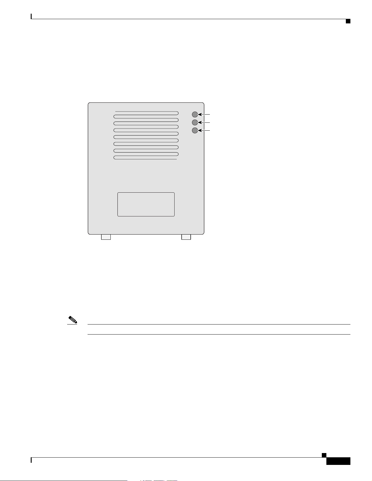
The three indicators on top of the access point report Ethernet activity, association status, and radio
activity as shown in Figure 1-1.
Figure 1-1 Indicators on the 1200 Series Access Point
Radio
Status
Ethernet
74046
The Ethernet indic ator signals Ethernet traffic on the wired LAN. This indicator blinks green when
•
a packet is received or transmitted over the Ethernet infrastructure. The indicator blinks red when
the Ethernet cable is not connected.
• The association sta tus indic ato r sign als o pe ratio nal s tatus. Blinki ng gree n ind i cates t hat the acc ess
point is operating normally but is not associated with any wireless client devices. Steady green
indicates that the access point is associated with at least one wireless client device.
• The radio indicator blinks green to indicate radio traffic activity. The light is normally off, but it
blinks green whenever a packet is received or transmitted over the access point radio.
Note The Radio and St at us in dica tor s a re u s ed f or both 2. 4- GHz a nd 5- GHz r a dio o pe rat ion.
OL-2155-02
Cisco Aironet 1200 Series Access Point Hardware Installation Guide
1-5
Page 18
Key Features
Draft Copy - CISCO CONFIDENTIAL
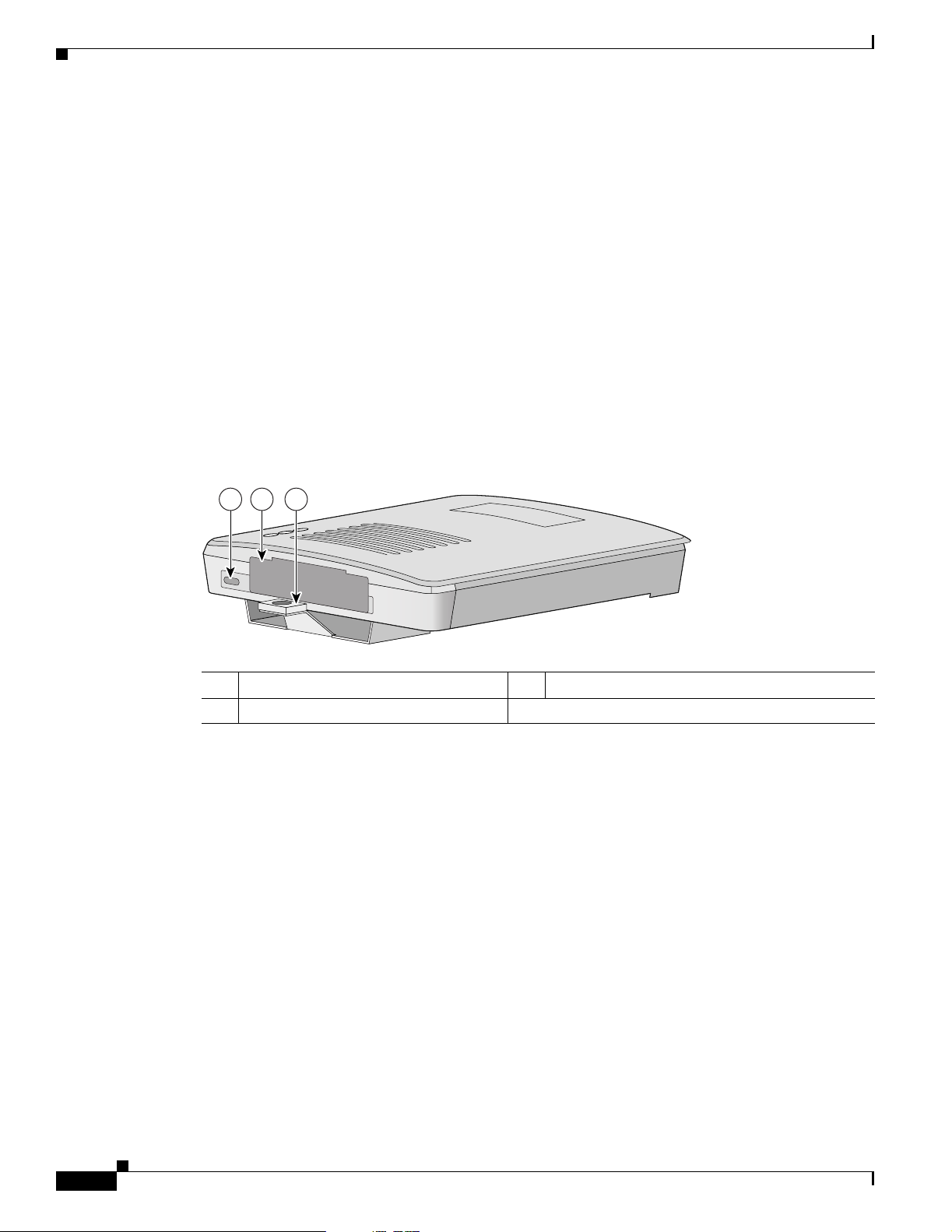
Security Lock Feature
The access point provides two methods of securing the access point to help prevent theft (see
Figure 1-2):
• Security hasp
• Security cable keyhole
The security hasp on the mounting bracket allows you to lock the access point to the bracket to make it
more secure. When the access point is properly installed on the mounting bracket, the holes in the
security hasps line up so you can install a pa dlock. Compatible padlocks are Master Lock models 120T
or 121T.
When using the security hasp with a lock, the access point is secured to the mounting bracket and the
mounting bracket sc rews alon g w ith th e 2. 4-G Hz radi o a cce ss cover ar e not ac cessib le.
The security cable keyhole allows you to secure the access point using a standard security cable, such as
the security cabl es us ed on l a ptop co mp uter s.
Figure 1-2 Access Point Security Points
Chapter 1 Overview
21 3
74344
1 Security cable keyhole 2 5-GHz module slot access cover
3 Security hasp for padlock
1-6
Cisco Aironet 1200 Series Access Point Hardware Installation Guide
OL-2155-02
Page 19
Chapter 1 Overview
Draft Copy - CISCO CONFIDENTIAL
Network Configuration Examples
This section describes the access point ’s role in three commo n wireless networ k configurati ons. The
access point’s de fault configura tion is as a roo t unit on a wire d LAN. The othe r two possible ro les,
repeater unit and central unit in an all-wireless network, require specific changes to the default
configuration.
Note The following network configurati on examples ap ply to both 2.4 -GH z and 5-GHz wireless LA Ns.
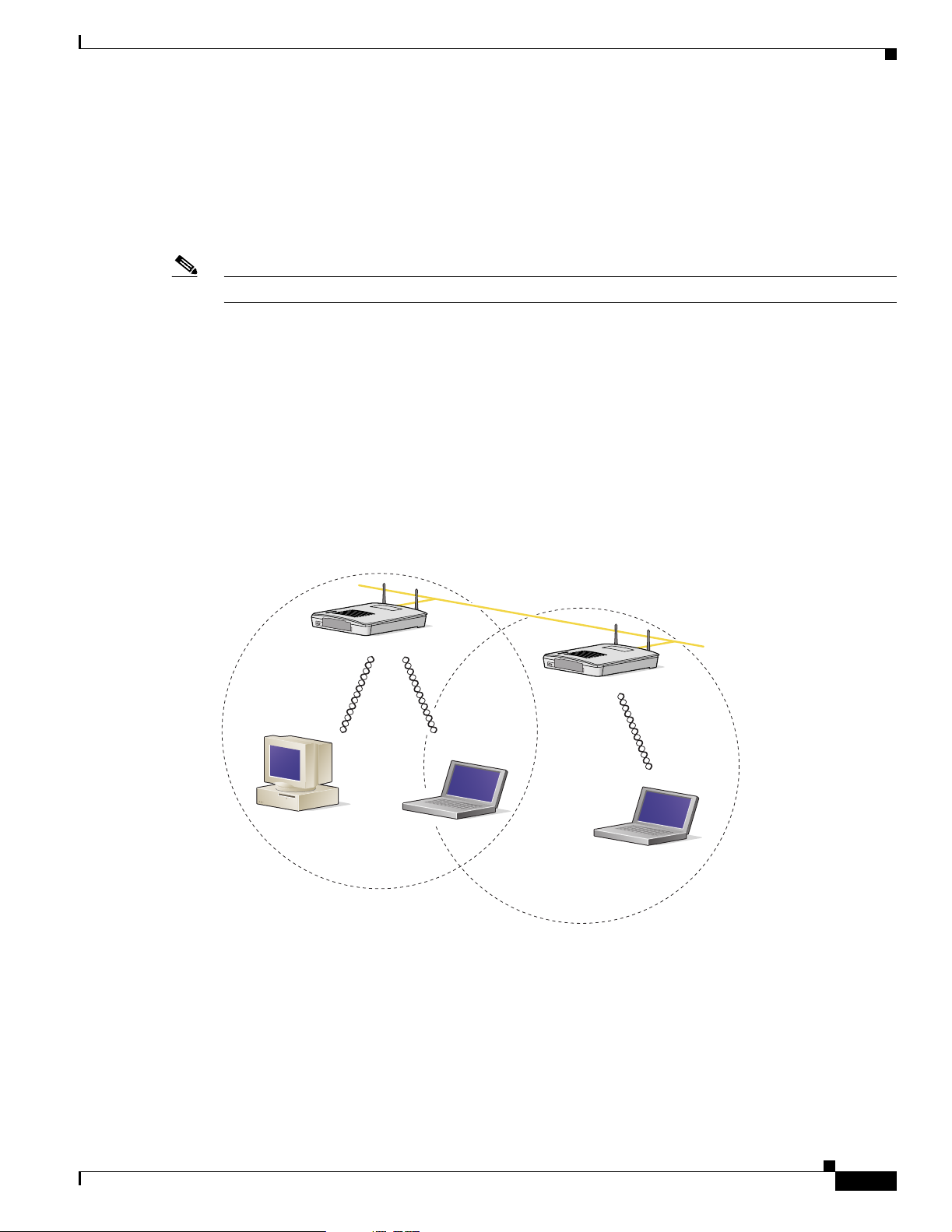
Root Unit on a Wired LAN
An access point connected directly to a wired LAN provides a connection point for wireless users. If
more than one access poi nt is connected to the LAN, users c an roam from one area of a fac ility to another
without losing thei r conn ect ion to t he ne twork. A s users move out o f range o f one a ccess poi nt, they
automatically con nect to the network (assoc iate) th rough anot her acces s point . The roami ng proce ss is
seamless and transparent to th e user. Figure 1 -3 shows access poin ts actin g as ro ot unit s on a wir ed LAN.
Network Configuration Examples
Figure 1-3 Access Points as Root Units on a Wired LAN
Access Point
(Root Unit)
Wired LAN
Access Point
(Root Unit)
65999
OL-2155-02
Cisco Aironet 1200 Series Access Point Hardware Installation Guide
1-7
Page 20
Network Configuration Examples
Draft Copy - CISCO CONFIDENTIAL
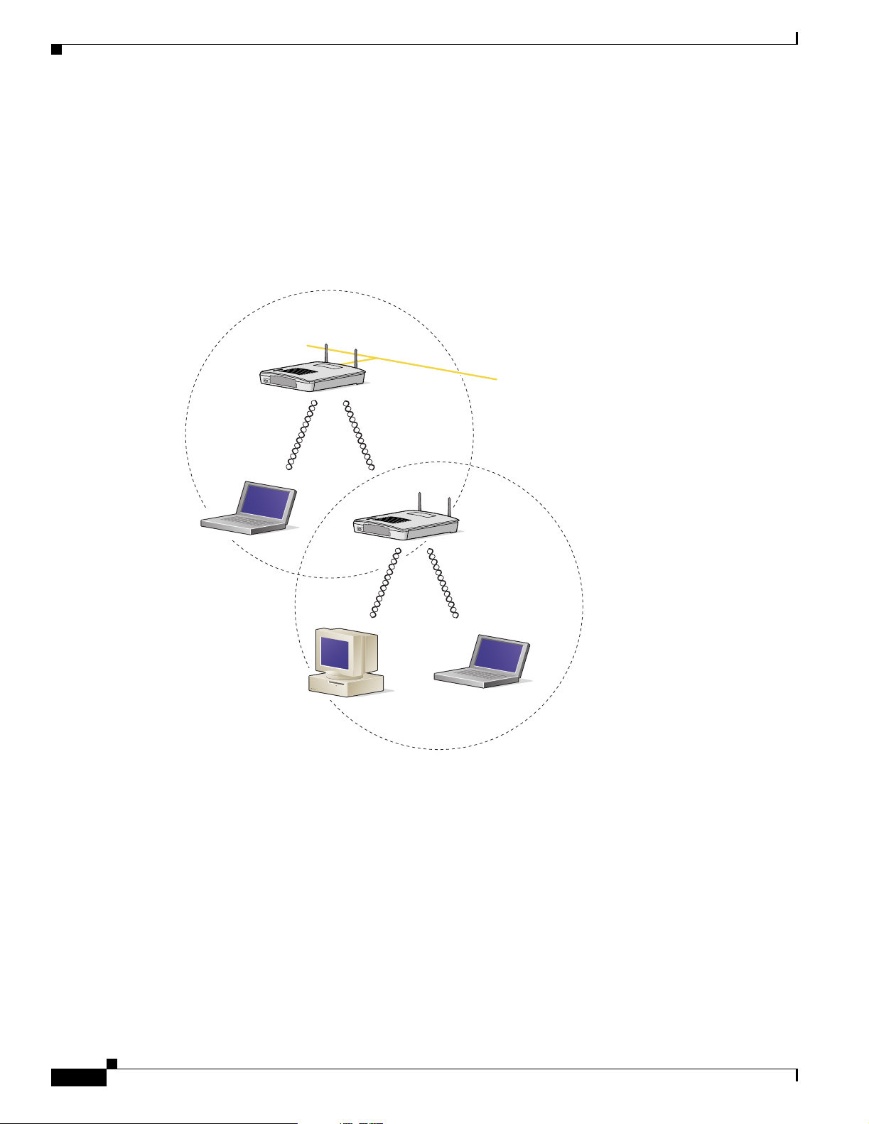
Repeater Unit That Extends Wireless Range
An access point can be configured as a stand alone repeater to extend the range of your infrastructure or
to overcome an obstacle that blocks radio communication. The repeater forwards traffic between
wireless users and the wired LAN by sending packets to ei ther an other repe ater or to an a ccess poi nt
connected to the wired LAN. The data is sent through the route that provides the greatest performance
for the client. Figure 1-4 shows an access point acting as a repeater.
Figure 1-4 Access Point as Repeater
Access Point
(Root Unit)
Chapter 1 Overview
Wired LAN
Access Point
(Repeater)
66000
1-8
Cisco Aironet 1200 Series Access Point Hardware Installation Guide
OL-2155-02
Page 21
Chapter 1 Overview
Draft Copy - CISCO CONFIDENTIAL
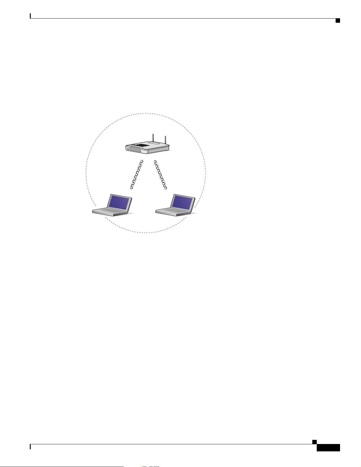
Central Unit in an All-Wireless Network
In an all-wireless network, an access point acts as a stand-alone root unit. The access point is not
attached to a wired LAN; it functions as a hub linking all stations together. The access point serves as
the focal point for communications, increasing the communication range of wireless users. Figure 1-5
shows an access point in an all-wireless network.
Figure 1-5 Access Point as Central Unit in All-Wireless Network
Access Point
(Root Unit)
Network Configuration Examples
65998
OL-2155-02
Cisco Aironet 1200 Series Access Point Hardware Installation Guide
1-9
Page 22

Chapter 1 Overview
Access Point Specifications
Draft Copy - CISCO CONFIDENTIAL
Access Point Specifications
The access point specifications are listed in Table 1-1.
Table 1-1 Access Point Specifications
Category Access Point with 2.4-GHz Radio Access Point with 5-GHz Radio Module
Size 6.56 in. W x 7.23 in. D x 1.66 in. H
16.67 cm W x 1 8.36 cm D x 4 .22 cm H
Status Indicators Three indicators on t he top pa nel : E therne t t raffic, status, a nd ra dio tra ffic
Connectors Back panel (left to right): reverse-TNC antenna connector; power connector (for plug-in AC power
module); RJ-45 connector for 10/100 BASE-T Ethernet connections; upside down RJ-45 connector
for serial connections; reverse-TNC antenna connector.
Front Panel: Card Bus connector used for the 5-GHz radi o module .
Input Voltage 48VDC nominal. Oper ation al up to 60VD C. Voltage higher than 60VDC can dama ge the unit.
Input Current With 2.4 GHz radio:
125 mA (typical)
The access point is capable of drawing 380 mA depending upon the current radios and future radios
installed in the unit.
Operating Temperature Access point:
–4 to 131
o
F (–20 to 55oC)
With the 5-GHz antenna in the patch position:
6.56 in. W x 8.04 in. D x 2.21 in. H
16.67 cm W x 20.42 cm D x 5.61
With 5-GHz radio:
TBD mA (typical)
With 2.4-GHz and 5-GHz radios
225 mA (typical)
Access point:
–4 to 113
o
F (–20 to 45oC)
1200 series power injector:
32 to 104
Storage Temperature –40 to 185
o
F (0 to 40oC)
o
F (–40 to 85oC) –40 to 185oF (–40 to 85oC)
Weight Without mounting bracket:
1.6 lbs (0.73 kg) wi th 2 .4- GHz ra dio
module
Power Output 100, 50, 30, 20, 5, or 1 mW
(Depending on t h e regul ato ry do mai n in
which the access point is installed)
Frequency 2.400 to 2.497 G Hz
(Depending on t h e regul ato ry do mai n in
which the access point is installed)
1200 series power inje ctor :
32 to 104
o
F (0 to 40oC)
Without mounting bracket:
1.87 lbs (0.85 kg) with 5-Gh z radio mo dule
1.97 lbs (0.89 kg) with 5-GHz radio module and
2.4-GHz radio
40 mW (16 dBm)
20 mW (13 dBm)
10 mW (10 dBm)
5 mW (7 dBm)
Note These values are based on the FCC peak
measurement method as defined in
FCC 15.407 (A)( 4)
UNII 1—5.15 to 5.25 GH
UNII 2—5.25 to 5.35 GHz
(Depending on the regulat ory doma in in whic h the
access point is installed)
1-10
Cisco Aironet 1200 Series Access Point Hardware Installation Guide
OL-2155-02
Page 23

Chapter 1 Overview
Access Point Specifications
Draft Copy - CISCO CONFIDENTIAL
Table 1-1 Access Point Specifications (continued)
Category Access Point with 2.4-GHz Radio Access Point with 5-GHz Radio Module
Range Indoor:
150 ft at 11 M bps
350 ft at 1 Mbps
Outdoor:
800 ft at 11 M bps
2000 ft at 1 M bp s
Modulation Direct Sequence Spread Spectrum (DSSS) Orthogonal Frequency Division Multiplex (OFDM)
Data rates 1, 2, 5.5, and 11 Mbps 6, 9, 12, 18, 24, 36, 48, and 54 Mb ps
Antenna A diversity system with two reverse-TNC
connectors (Cisco antennas are sold
separately).
Compliance The 1200 series access point complies with UL 2043 for products installed in a building’s
environmental air handling spaces, such as above suspended ceilings.
Indoor:
TBD ft at 6 Mbps
TBD ft at 54 Mbps
Outdoor:
TBD ft at 6 Mbps
TBD ft at 54 Mbps
A diversity system consisting of two integrated
omnidirectional and two integrated di rection al
antennas.
Caution The 12 00 seri es power inj ect or s are n ot teste d to U L 20 43 and sh ould n ot be pl ace d in a
building’s environme ntal air space, such as above suspended ceilings.
Note If you plan to mount the access point in environmental air space using a 5-GHz radio, Cisco
recommends that you mount the access point horizontally with its antennas pointing down.
Doing so will result in the access point complying with regulatory requirements for
environmental air space with the 5-GHz radio installed.
Safety Designed to meet:
• UL 1950 Third Edition
• CSA 22.2 No. 950- 95
• IEC 60950 Second Edition, inc luding
Amendments 1-4 with all deviations
• EN 60950 Second Edition, including
Amendments 1-4
Radio Approvals FCC Part 15.247
Canada RSS-139-1, R SS-21 0
Japan Telec 33B
EN 300.328
EMI and Susceptibility FCC Part 15.107 and 15.109 Class B
ICES-003 Class B (C anad a)
EN 55022 B
AS/NZS 3548 Class B
VCCI Class B
EN 55024
EN 301.489-1
EN 301.489-17
RF Exposure OET-65C
RSS-102
ANSI C95.1
Designed to meet:
• UL 1950 Third Edition
• CSA 22.2 No. 950-95
• IEC 60950 Second Edition, incl uding
Amendments 1-4 with all deviations
• EN 60950 Second Ed i tion, inc ludi ng
Amendments 1-4
FCC Part 15.4 07
Canada RSS-210
Japan ARIB STD-T71
EN 301.893
OL-2155-02
Cisco Aironet 1200 Series Access Point Hardware Installation Guide
1-11
Page 24

Access Point Specifications
Chapter 1 Overview
Draft Copy - CISCO CONFIDENTIAL
1-12
Cisco Aironet 1200 Series Access Point Hardware Installation Guide
OL-2155-02
Page 25

CHAPTER
Installation
This chapter describes the setup of the access point and includes the following sections:
• Safety Informat ion, p ag e 2-2
• Wa rn ings, p age 2-3
• Installation Guidelines, page 2-4
• Unpacking the Access Po int, page 2-6
• Before Beginning the I nsta llat ion, pag e 2-7
• Installation Summary, page 2-8
• Connecting the 2.4-GHz Antennas, page 2-8
• Connecting the Ethernet and Power Cables, page 2-9
2
OL-2155-02
Cisco Aironet 1200 Series Access Point Hardware Installation Guide
2-1
Page 26

Safety Information
Draft Copy - CISCO CONFIDENTIAL
Safety Information
Follow the guidelines in this section to ensure proper operation and safe use of the access point.
FCC Safety Compliance Statement
The FCC, with its action in ET Doc ket 96-8, has adop ted a safe ty standard for human exposur e to RF
electromagnetic energy emitted by FCC-certified equipment. When used with approved Cisco Aironet
antennas, Cisco Aironet products meet the uncontrolled environmental limits found in OET-65 and ANSI
C95.1, 1991. Proper operation of this radio device according to the instructions in this publication will
result in user exposure substantially below the FCC recommended limits.
General Safety Guidelines
• Do not touch or move the antenna while the unit is transmitting or receiving.
• Do not hold any component containing a radio such that the antenna is very close to or touching any
exposed parts of the body, especially the face or eyes, while transmitting.
• Do not operate the radio or attempt to transmit data unless the antenna is connected; otherwise, the
radio may be damaged.
Chapter 2 Installation
• Use in specific environme nts :
–
The use of wireless devices in hazardous locations is limited to the constraints posed by the
local codes, the national codes and the safety directors of such environments.
–
The use of wir eless d evices on airpl ane s is governed by the Fede ra l Aviation Administrat ion
(FAA).
–
The use of wireless devices in hospitals is restricted to the limits set forth by each hospital.
• Antenna use:
–
High-gain wall-mount or mast-mou nt antenna s are designe d to be professi onally in stalled.
Please contact your professional installer, VAR, or antenna manufacturer for proper installation
requirements.
2-2
Cisco Aironet 1200 Series Access Point Hardware Installation Guide
OL-2155-02
Page 27
Chapter 2 Installation
Warnings
Warnings
Draft Copy - CISCO CONFIDENTIAL
Translated versions of the following safety warnings are provided in Appendix A, “Translat ed Sa fet y
Wa rn ings.”
Warning
Warning
Warning
Warning
Warning
Warning
In order to comply with FCC radio frequency (RF) exposure limits, dipole antennas should be located
at a minimum of 7.9 inches (20 cm) or more from the body of all persons.
Do not operate your wireless network device near unshielded blasting caps or in an explosive
environment unless the device has been modified to be especially qualified for such use.
Do not locate the antenna near overhead power lines or other electric light or power circuits, or
where it can come into contact with such circuits. When installing the antenna, take extreme care
not to come into contact with such circuits, as they may cause serious injury or death. For proper
installation and grounding of the antenna, please refer to national and local codes (e.g. U.S.:NFPA 70,
National Electrical Code, Article 810, in Canada: Canadian Electrical Code, Section 54).
Do not work on the system or connect or disconnect cables during periods of lightning activity.
Read the installation instructions before you connect the system to its power source.
This product relies on the building's installation for short-circuit (overcurrent) protection. Ensure that
a fuse or circuit breaker no larger than 120 VAC, 15A U.S. (240 VAC, 10A international) is used on the
phase conductors (all current-carrying conductors).
OL-2155-02
Cisco Aironet 1200 Series Access Point Hardware Installation Guide
2-3
Page 28
Installation Guidelines
Draft Copy - CISCO CONFIDENTIAL
Installation Guidelines
This section describes th ings to keep in mind w hen install ing your ac cess point. Sections in clude:
• Basic Guidelines
• Installation Above Suspended Ceilings
• Coverag e Optio ns
• Site Surveys
Basic Guidelines
Because the access point is a radio device, it is susceptible to common causes of interference that can
reduce throughpu t a nd ra nge . Foll ow these b asic gu ide lin es t o ensu re the b es t pos sibl e perfo rm an ce:
• Install the acces s po int i n an a rea wher e lar g e st eel st ructu res s uch a s sh elving units , boo kcase s, an d
filing cabinets do no t ob struc t radi o sign als to a nd from the ac cess point .
• Install the access point away from microwave ovens. Microwave ovens operate on the same
frequency as the access point and can cause signal interference.
Chapter 2 Installation
Installation Above Suspended Ceilings
The access point uses a me tal encl osure having adequat e fire resistan ce and low smoke-pr oducing
characteristics suitable for operation in a building’s environment al air space i n acco rdanc e wit h
Section 300-22(c) of the NE C, such as above suspende d ceilings. For mo unting inst ruction s refer to
Chapter 4, “Mo unting In structi ons.”
Caution The 1200 series power injectors are not tested to UL 2043 and should not be placed in a building ’s
enviro nmental air space, such as above suspended ceilings.
Note If you plan to mount the access point in environmental air space using a 5-GHz radio, Cisco recommends
that you mount the access point h orizonta lly with i ts antennas p ointing down. Doing so will result in the
access point complying with regulatory requirements for environmental air space with the 5-GHz radio
installed.
2-4
Cisco Aironet 1200 Series Access Point Hardware Installation Guide
OL-2155-02
Page 29
Chapter 2 Installation
Draft Copy - CISCO CONFIDENTIAL
Coverage Options
The network architecture options of wireless stations and access points provide for a variety of coverage
alternatives and flexibility. The network can be designed to provide a wide coverage area with minimal
overlap or a narrow coverage ar ea wit h heavy overla p. A na rrow coverage are a wi th h eavy overla p
improves network performance and pr otec ti on aga inst downtime if a c om ponent fails.
Note The following coverage options apply to both 2.4-GHz and 5-GHz wireless LANs.
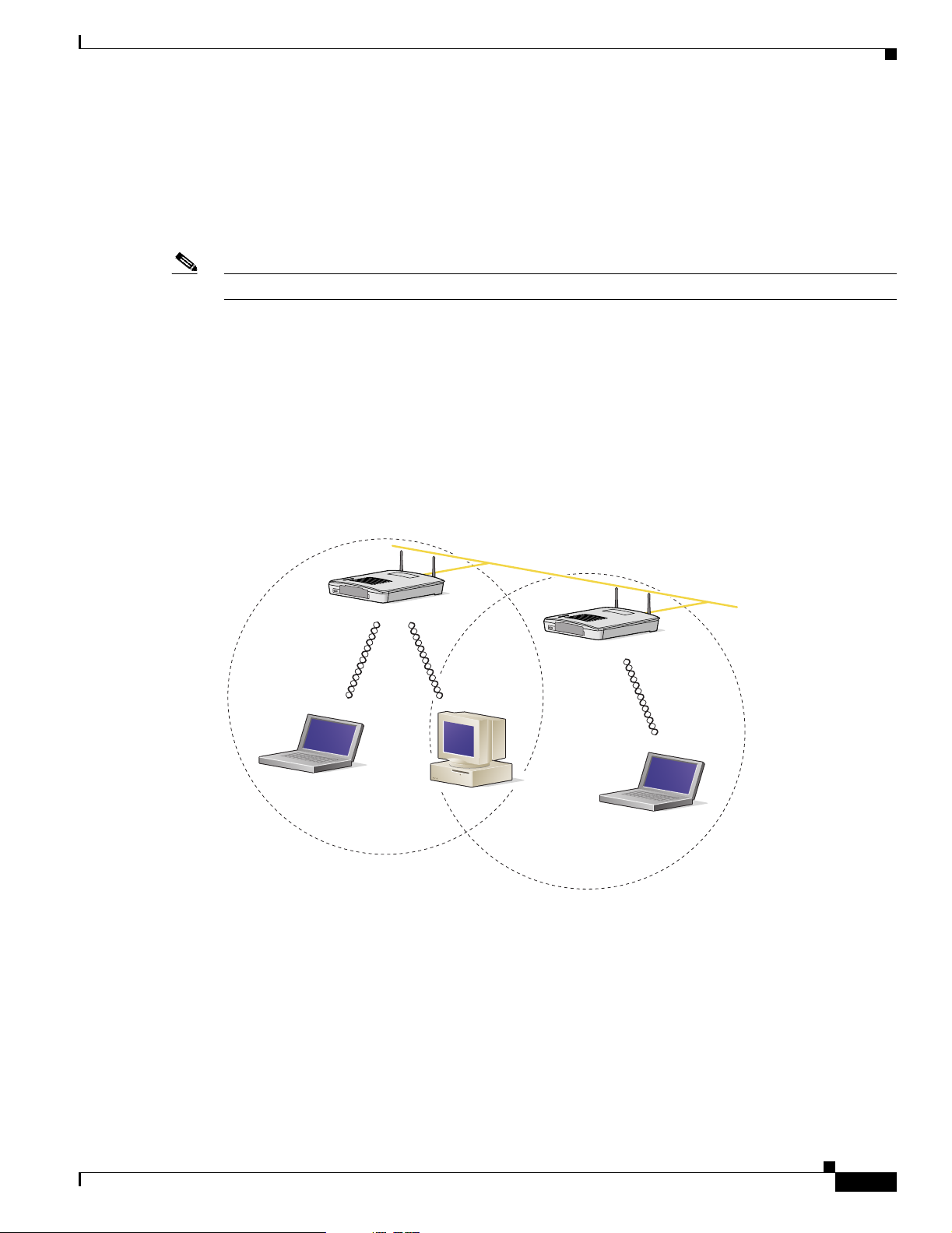
Minimal Overlap Coverage Option
By arranging the access points so that the overlap in a coverage area is minimized, a large area can be
covered with minimal cost (see Figure 2-1 ). The total bandwidth available to each wireless client device
depends on the amount of data ea ch mob ile stat ion ne eds to transfe r an d the num be r of stat ion s loca ted
in each cell. Seamless roaming is supported as a client device moves in and out of range of each access
point, thereby maintai ning a const ant con nection to the wi red LAN. Ea ch device in the ra dio network
must be configured with the same SSID to provide roaming capability.
Installation Guidelines
Figure 2-1 Minimal Overlap Coverage Option
Heavy Overlap Coverage Option
Wired LAN
74001
OL-2155-02
By arranging the access points so the overlap in coverage area is nearly maximized, a large number of
mobile stations c an be supp orted in the sam e w irele ss infra stru ctur e. H owever, devices in overlapping
coverage areas on the same frequency will detect adjacent cell traffic and delay transmissions that would
cause collisions . This co nfigurat ion redu ce s the a ggregate ra dio s ystem throug hpu t . Heavy cell overlap
is not recommende d for m axi mum sy st em t hroug hpu t.
Cisco Aironet 1200 Series Access Point Hardware Installation Guide
2-5
Page 30

Unpacking the Access Point
Site Surveys
Chapter 2 Installation
Draft Copy - CISCO CONFIDENTIAL
Because of the redundancy in coverage overlap, network access is not lost if an access point fails. Upon
failure of the access point, the station automatically roams to an operational access point. With this
architecture, eac h device in t he R F net work mu st b e c onfigur ed w it h th e sam e SSID to p rovide the
roaming capability.
Because of differen ces i n comp one nt co nfigurati on, pla cem ent , an d physi cal environmen t, every
network application is a unique instal lation. Before installing multiple access points, you should perform
a site survey to determine the optimum utilization of networking components and to maximize range,
coverage, and network p erfor ma nce.
When supporting d ual mode 2. 4-GH z a nd 5-G Hz opera ti on, yo u ma y have to pe rfo rm a sit e sur vey for
each of the operating frequenc ies.
Consider the following operating and environmental conditions when performing a site survey:
• Frequency—The radio coverage area for the 5-GHz radio is less than the coverage area for the
2.4-GHz radio.
• Single- and dual-band op eration—When suppo rti ng bo th sing le an d dua l ba nd acc ess p oint s, yo u
should perform a site survey for each of th e operat ing freq uencie s.
• Data rates—Sensitivity and range are inversely proportional to data bit rate s. The maxi mum radi o
range is achiev ed at the lo west workable dat a rate. A decrease in rece iver th reshold sensiti vity occurs
as the radio data increases.
• Antenna type and p lacement—Proper antenna configuration is a critical factor in maximizing radio
range. As a general rule, range incre ases in prop ortion to antenn a height.
• Physical environment—C lear or open areas provide better radio range than closed or filled areas.
Also, the less cluttered the work environment, the greater the range.
• Obstructions—A physi cal obstr uctio n su ch a s m eta l sh elvi ng or a stee l p ill ar ca n hi nder
performance of wireless devices. Avoid locating the devices in a location where there is a metal
barrier between the sendi ng and rec eiving antennas.
• Building materials—Radio penetration is greatly influenced by the building material used in
construction. For example, drywall construction allows greater range than concrete blocks. Metal or
steel construction is a barri er to radio signa ls.
Unpacking the Access Point
Follow these steps to unpack the access point:
Step 1 Open the shipping container and carefully remove the contents.
Step 2 Return all pack ing mat erials t o the shi pping cont ai ner a nd save it.
2-6
Step 3 Ensure that all items listed in the “Package Contents” section are included in the shipment . Check each
item for damage . If a ny item i s dama ged or m issin g, no tif y y our aut hori zed Cisc o s ale s rep res enta tive.
Cisco Aironet 1200 Series Access Point Hardware Installation Guide
OL-2155-02
Page 31

Chapter 2 Installation
Draft Copy - CISCO CONFIDENTIAL
Package Contents
Each access point pack age co ntain s the foll owing items:
• Cisco Aironet 1200 Series Acces s Point
• Cisco Aironet 1200 Series Power Module (Universal power supply)
• Quick Start Guide: Cis co A ironet 1200 Seri es A cce ss Point
• Cisco product registration an d Cisco docum entati on feedba ck card s
Before Beginning the Installation
Before you begin the i nsta llati on proc ess, p l ease refe r t o Figure 2-2 and Figure 2-3 to become familiar
with the access point’s l ayo ut, co nnec tors, a nd 5- GHz m odul e l ocat ion.
Figure 2-2 Access Point Layout and Connectors
Before Beginning the Installation
1 2 3 4 6
5
65847
7 1
1 2.4-GHz antenna connec tors 5 Mode button (possible future feature)
2 48VDC power port 6 Status LEDs
3 Ethernet port (RJ-45 ) 7 Mounting bracket
4 Console port (RJ-45)
Figure 2-3 5-GHz Radio Module
1 1 2 3
OL-2155-02
74631
1 5-GHz radio modul e m oun tin g scr ews 2 5-GHz radio module antenna (patch posi tion)
3 Access point
Cisco Aironet 1200 Series Access Point Hardware Installation Guide
2-7
Page 32

Installation Summary
Draft Copy - CISCO CONFIDENTIAL
Installation Summary
During the installation of the access point, you will perform the following operations:
• Connect a single antenna or dual diversity antennas (refer to the “Connecting the 2.4-GHz
Antennas” section on page 2-8).
• Connect Ethern et an d power cables (ref er to the “Con necting t he Etherne t and Power Cables”
section on page 2-9).
• Configure basic settings (refer to Chapter 3, “Basic Configuration”).
• Mount the access point to a ceiling or wall. For additional information, refer to Chapte r 4,
“Mounting Instructio ns.”
• Configure security and other acc ess point op tions. For addit ional informati on, refe r to the Cisco
Aironet 1200 Series Access Point Software Configuration Guide.
Connecting the 2.4-GHz Antennas
Chapter 2 Installation
The access po int sup por ts a si ngl e an t enna or du al diversity ant enna s. Two R-TNC antenna co nne cto rs
are provided on the back of th e unit for the 2.4-G Hz radio.
If you are using a Cisc o Ai rone t 2 dB i a nten na , fol low the step s be low:
Step 1 Attach an antenna t o the Right/Primary 2.4-GHz (R-TNC) antenna conn ect or on the b ack o f the ac cess
point and tighten hand t ight. I f you a re us in g two ant enna s for diversity coverage , a ttac h th e secon d
antenna to th e Left 2.4- GH z ( R-T N C) an ten na conn ec to r.
Step 2 Orient the ante nna dep endi ng on how you i nte nd t o mount th e acc ess poin t.
• On a table or desk, orient the ant enna strai ght up.
• On a vertical surface, such as a wall, orient the antenna straight up.
• On a ceiling, orient the antenna straight down.
If you are using another Cisc o Aironet antenna, re fer to the in structi ons that cam e with your a ntenna .
2-8
Cisco Aironet 1200 Series Access Point Hardware Installation Guide
OL-2155-02
Page 33

Chapter 2 Installation
Draft Copy - CISCO CONFIDENTIAL
Connecting the Ethernet and Power Cables
The access point rec eives power through the Eth ernet ca ble or a 120 0 series power module (u niversal
power supply). Figure 2-4 shows the power options for the access point.
Figure 2-4 Access Point Power Options
Option 1 Option 2 Option 3
Switch
(without inline power)
S
YST
1
RPS
2
3
4
S
T
A
T
5
UT
IL
DUP
LX
6
SP
E
ED
7
8
10Base-T / 100Base-TX
9
MO
Switch with
DE
inline power
SY
S
T
1
RP
S
2
3
4
T
AT
5
UT
ILS
DUPLX
6
SPEE
D
7
8
10Base-T / 100Base-TX
9
MOD
E
10
11
12
13
14
15
16
17
18
Catalyst 29
19
50
S
E
R
20
IE
S
21
22
100Base-FX
23
24
23
24
10
11
12
13
14
15
16
17
18
19
20
21
Inline Power
Patch Panel
Catalyst 2950
SE
RIES
22
100Base-FX
23
24
23
24
Connecting the Ethernet and Power Cables
Switch
(without inline power)
SYST
1
R
P
S
2
3
4
STAT
5
U
TIL
DUPL
X
6
S
P
EED
7
8
10Base-T / 100Base-TX
9
MOD
E
10
11
12
13
14
15
16
17
18
Catalyst 2950
19
S
E
RI
20
E
S
21
22
100Base-FX
23
24
23
24
S
YS
T
RPS
ST
A
T
UTIL
DUPLX
SPEED
MODE
Power injector
ORK
W
T
O
E
T
AP/
BR
N
TO
I
D
G
E
Power
cord
Universal
power supply
Access Point
The access point power options are listed below:
• A switch with inline power, such as a Cisco Catalyst 3524-PWR-XL Switch
• An inline power patch pa nel, s uch a s a Ci sco Catal yst In line Power Patch Panel
• A 1200 series power injector
• A 1200 series power module (Universal power supply)
Caution The 1200 series power injectors are not tested to UL 2043 and should not be placed in a building ’s
enviro nmental air space, such as above suspended ceilings.
74164
OL-2155-02
Note If you use in-line power from a switch or pa tch panel, do no t connec t the 1200 serie s power module to
the access point. U s i ng two power sources on the access point might cause the switch or patch pa nel to
shut down the port to which the access point is conne cted.
Note If you need to use a power module or power injector to power the acce ss point, you mu st use the
1200 series power module or power injector. The 350 series power module and power injec tor are not
compatible with the 1200 series access point.
Cisco Aironet 1200 Series Access Point Hardware Installation Guide
2-9
Page 34

Connecting the Ethernet and Power Cables
Draft Copy - CISCO CONFIDENTIAL
Note Only the 1200 series power inject or and the 120 0 series power mod ule can suppor t simulta neous
operation of both the 2.4-G Hz and th e 5.0-GH z radios in the access poi nt.
Note Both the Ethernet and console ports use RJ-45 connectors. Be careful to avoid accidently connecting the
serial cable to the Ethernet port connector.
Follow these steps to connect the Ethernet and power cables to the access point:
Step 1 If you are using in-line power fro m a switch or pa tch panel , connec t an Etherne t cable from the ac cess
point to the device that supplie s power.
Step 2 If you are using in-line power fro m a 1200 ser ies power injec tor, follow these additiona l steps:
a. Connect an Ethernet cable from the access point into the end of the 1200 series power injector
labeled To AP/ Bridge.
b. Connec t an Et he rnet cable from the end of the 1200 se rie s power injector labeled To Network to the
your 10/100 Ethe rn et L AN .
c. Plug the female end of the AC power cord in to t he 1200 seri es power m odul e (U niversal power
supply) and plug the male end into a suitab le AC power receptacle.
Chapter 2 Installation
Step 3 If you are using a 1200 series power module, follow these additio nal step s:
a. Connect an Ethernet cable from the acces s point to your 10/10 0 Ethern et LAN .
b. Plug the female end of the power cord into the 1200 series power module (Universal power supply)
and plug the male end into a sui table power re cepta cle.
c. Plug the power connector into the back of the access point.
At startup, all three LEDs on the top of the access point slowly blink amber, red, and green in sequence;
the sequence takes a few minutes to complete. During normal operation, the LE Ds b link gree n. Refer to
Chapter 7, “Troubleshooti ng,” for LED descript ions.
Refer to Chapter 3, “Basic Con figuration,” to assign basic settings to the a ccess point.
2-10
Cisco Aironet 1200 Series Access Point Hardware Installation Guide
OL-2155-02
Page 35

CHAPTER
3
Basic Configuration
This chapter describes the initial configuration of the access point using the Internet browser-based
management system and the serial interface. Y ou can also reach the management system through a Telnet
session. Consult the Cisco Aironet 1200 Series Access Point Softwar e Configuration Guide for complete
instructions on using these interfaces.
This chapter includes the following sections:
• Before You Star t, page 3-2
• Summary of Configuration Steps, page 3-2
• Using the IP Setup Utility, page 3-3
• Entering Basic Settin gs, pa ge 3-6
• Default Basic Settings, page 3-13
OL-2155-02
Cisco Aironet 1200 Series Access Point Hardware Installation Guide
3-1
Page 36

Before You Start
Draft Copy - CISCO CONFIDENTIAL
Before You Start
Before configuring the access point, you need to obtain t he following informa tion (possi bly from your
network administrator):
• The service set identifier (SSID) for the access point. If dual-band radio operation is supported,
different SSIDs for 2.4 GHz and 5-G Hz operat ion may be u sed.
• A system name for the access point. The name should describe the location or principal users of the
access point. The access point default system name is AIR-AP1200-xxxxxx, where xxxxxx is the last
6 digits of the access point MAC address.
• If your network does not use DHCP or BOOTP to assign IP addresses, you need the fo llowing:
–
–
–
• The access poin t’s MAC address, which is pr i nted on t he labe l o n th e bott om of t he ac cess poin t.
• Security settings for th e wireless netw ork, such as WEP, LEAP, and MIC settings. Dif ferent s ecurity
settings may be used for the 2.4-GHz and 5-GHz wireless LANS. For additional information on
configuring the access point security settings, refer to the Cisco Aironet 1200 Series Access Point
Software Configuration Guide.
Chapter 3 Basic Configuration
IP address for the access point
IP address for the defa ult ga teway
IP subnet mask for the access point
Summary of Configuration Steps
You use t he E xp ress Set up page to ass ign b asic s etti ngs to th e acc ess po int. For in struct ions on set ting
up security , f ilte ring, and othe r access point featu res, refer to the Cisco Air onet 1200 Series Access Point
Software Configuration Guide.
You will follow these general steps to enter the access point’s basic settings:
1. Connect the Ethernet and power cables to the access point. For instructions refer to the “Connecting
the Ethernet and Power Cables” section on page 2-8.
2. Use an Interne t br owser to op en the ac cess poi nt’s manage ment syst em by browsing t o th e acc ess
point’s IP address or use a terminal emulator an d the ser ial co nsole port.
If your network uses a DHCP server and you are using a Windows operating system (Windows 95,
98, NT, 2000, ME, or XP), you can use the IP Setup Utility (IPSU) to find the acc ess point ’s
DHCP-assigned IP address. For othe r operating syst ems, you mu st use the seri al console port. For
additional information on IPSU, refer to the “Using the IP Setup Utility” section on page 3-3.
To use the console port, you must connect an RJ-45 to DB-9 serial cable (refer to Appendix C,
“Console Cable Pinout s”) to your comput er’s COM po rt a nd to th e c on sole por t on t he back of the
access point and use a terminal emulator to open the management system. For additional information
on using the console port, re fer to th e “Using a Terminal Emulator” section on page 3-9.
3. Enter basic settings on the Express Setup page as described in the “Entering Basic Settings” section
on page 3-6.
4. Mount the access point to the ceiling or wall. For mounting instructions, refer to Chapter 4,
“Mounting Instructio ns.”
5. Enter security and other access point option settings. Fo r additional information, refer to the Cisco
Aironet 1200 Series Access Point Software Configuration Guide.
3-2
Cisco Aironet 1200 Series Access Point Hardware Installation Guide
OL-2155-02
Page 37

Chapter 3 Basic Configuration
Draft Copy - CISCO CONFIDENTIAL
Using the IP Setup Utility
The IP Setup utility (IPSU) allows you to find the access point’s IP address when it has been assigned
by a DHCP server. You can also use IPSU to set the access point’s IP address and SSID if they have not
been changed from the defau lt setting s.
Note IPSU can be used only on th e following operating systems: Windows 95, 98, NT, 2000, ME, or XP. For
other operating systems, you must use the access point console port and a terminal emulator program to
configure the access point.
The sections below explain how to install the utility, how to use it to find the access point’s IP address,
and how to use it to set the IP address and the SSID.
Obtaining and Installing IPSU
IPSU is available on the Cisco web site. Follow these steps to obtain and install IPSU:
Using the IP Setup Utility
Step 1 Use your Internet browser to ac cess the Cisc o Softwa re Center at the following URL:
http://www.cisco.com/public/sw-center/sw-wireless.shtml
Step 2 Locate the utilities section and click on the individual files link for Windows.
Step 3 Click IPSUvxxxxx.exe. The vxxxxxx identifies the software package version number.
Step 4 Read and accept the terms and conditions of the Software License Agreement.
Step 5 Download and save the file to a temporary directory on your hard drive and then exit the Internet browser.
Step 6 Double-click IPSU vxxxxxx .exe in the temporary directory to expand the file.
Step 7 Double-click Setup.exe and follow the steps provided by the installation wizard to install IPSU.
The IPSU icon appears on your compu ter desktop .
Finding the Access Point’s IP Address
If your access point rece i v es an IP addr ess fr om a DH CP serv er, you can use IPSU to find its IP add ress.
You must run IPSU fr om a com pute r on the same subnet work as the a cces s point . Follow these steps to
find the access po int’s IP address:
Step 1 Double-click the IPSU icon on your computer d eskto p to st art t he ut ility.
OL-2155-02
Cisco Aironet 1200 Series Access Point Hardware Installation Guide
3-3
Page 38

Using the IP Setup Utility
Step 2 When the utility window opens, make sure the Get IP addr radio button in the Function box is selected.
Chapter 3 Basic Configuration
Draft Copy - CISCO CONFIDENTIAL
The IPSU scree n appe ars (s ee Figure 3-1).
Figure 3-1 IPSU Get IP Address Screen
Step 3 Enter the access point’s MAC address in the Device MAC ID field. The access point’s MAC address is
printed on the la bel on the bot tom of the uni t. It sh ould c onta in six pa irs of hexade cim al d igi ts. Your
access point’s M AC address might look like the fol lowing example:
000164xxxxxx
Note Th e MAC address field is not case-sensitive.
Step 4 Click Get IP Address.
Step 5 When the access point’s IP address appears in the IP Address field, write it down.
If IPSU reports that the IP address is 10.0.0.1, the default IP address, then the access point did not receive
a DHCP-assigned IP address. To change the access point IP address using IPSU, refer to the “Setting the
Access Point’s IP Address and SSID” section on page 3 -4. To change the access point IP address using
the console port, refer to the “A ssigning Ba sic Settings” section on page 3-9.
Setting the Access Point’s IP Address and SSID
You can use IPSU to change the default IP address and SSID of the access point.
Note The computer you use to assign an IP address to the access point must have an IP address of its own and
be located on the same subnet as the access point.
3-4
Note IPSU can change the access point’s IP address and SSID only from their default settings. After the IP
address and SSID have be en c ha nged, I PSU ca nnot cha ng e t he m aga in ( see th e “Using an Internet
browser” section on page 3 -6 or the “U sing a Terminal Emulator” section on page 3-9.)
Cisco Aironet 1200 Series Access Point Hardware Installation Guide
OL-2155-02
Page 39

Chapter 3 Basic Configuration
Note When using IPSU to change the SSID in a dual-mode access point, the SSIDs for both radios are changed
to the new setting.
Follow these steps to assign an IP address and an SSID to the access po int:
Step 1 Double-click the IPSU icon on your comp uter d eskto p to sta rt t he uti lity.
Step 2 Click the Set Parameters radio button in the Function box (se e Figure 3-2).
Figure 3-2 IPSU Set Parameters Screen
Using the IP Setup Utility
Draft Copy - CISCO CONFIDENTIAL
Step 3
Enter the access point’s MAC address in the Device MAC ID field. The access point’s MAC address is
printed on the la bel on the bot tom of the uni t. It sh ould c onta in six pa irs of hexade cim al d igi ts. Your
access point’s M AC address might look like the fol lowing example:
004096xxxxxx
Note Th e MAC address field is not case-sensitive.
Step 4 Enter the IP addr es s yo u want t o assi gn to the a cce ss poi nt i n t he I P A ddr es s field.
Step 5 Enter the SSID you want to assign to the access point in the SSID field.
Note You cannot set the SSID without also setting the IP address. However, you can set the IP address
without setting the SSID.
Step 6 Click Set Parameters to change the access point’s IP address and SSID settings.
Step 7 Click Exit to exit IPSU.
OL-2155-02
Cisco Aironet 1200 Series Access Point Hardware Installation Guide
3-5
Page 40

Entering Basic Settings
Draft Copy - CISCO CONFIDENTIAL
Entering Basic Settings
You can open the access point’s management system through your Internet browser or through the access
point’s console port using a terminal emulator. Each method is described in this section.
Using an Internet browser
Follow these steps to enter basic settings with an Internet browser:
Step 1 Enter or paste your access point’s IP address in the browser’s address or loca tion field; if you are using
Netscape, the fiel d is labele d Netsite or Location; if you are using Microsoft Internet Explorer, the field
is labeled Address. Press Enter.
Step 2 When the access poin t’s Summary Status pa ge appear s, click Setup. Whe n the Setup page ap pear s, cli ck
Express Setup. The Express Setup screen appears (Figure 3-3).
Note If the access point is new and its factory configuration has not been changed, the Express Setup
screen appears instead of the Summary Status screen when you first browse to the access point.
Chapter 3 Basic Configuration
Figure 3-3 Express Setup Screen
3-6
Step 3
Cisco Aironet 1200 Series Access Point Hardware Installation Guide
Enter a system n am e f o r the access point i n t he Sy s tem Na me field. A descriptive system name makes it
easy to identify the acc ess point on your network . The default system nam e is AIR -AP12 00-xx xxx x,
where xxxxxx is the last 6 digits of the access point MAC address.
OL-2155-02
Page 41

Chapter 3 Basic Configuration
Step 4 Select a configuratio n se rver pr ot ocol from th e Con figuratio n Server Pr otoc ol d rop -down arr ow menu.
The configuration server prot ocol you sele ct shoul d match you r network’s method of I P a ddres s
assignment. The Co nfigurati on Se rver l ink ta kes you t o th e Boot Server Setup p age, w hic h you use to
configure the access point to work with your network’s BOOT P or DHCP servers for automatic
assignment of IP addresses.
The Configuration Server Protocol drop-down menu optio ns includ e:
• None—Yo ur network does not have an automatic system for IP address assignment.
• BOOTP—With Bootstrap Protocol, IP addr esse s ar e assig ned bas ed on M AC addresses.
• DHCP—With Dynamic Host Configuration Protocol, IP addresses are “leased” for pre deter mined
Step 5 Enter an IP address in the Default IP address field.
• If DHCP is not enabled, the IP address entered is the access point’s static IP address.
• If DHCP or BOOTP is enable d, the address you enter in this fi eld provide s the IP address only whe n
Step 6 Enter an IP subnet mask in the Default IP Subnet Mask field to identify the subnetwork so the access
point’s IP address can be recognized on the LAN.
Entering Basic Settings
Draft Copy - CISCO CONFIDENTIAL
periods of time.
no server responds with an IP address for the a ccess poi nt.
• If DHCP or BOOTP is not enabled, this field is the subnet mask.
• If DHCP or BOOTP is enabled, this field provides the subnet mask only when no server responds to
the access point’s DHCP or BOOTP request.
Step 7 Enter the IP a ddr es s of y our de fau lt i nter ne t ga teway in the De fault Ga teway field. Th e ent ry
255.255.255.255 indicates no gateway. Clicking the Gateway link takes you to the Routing Setup page,
which you use to configure the access point to communic ate with the IP ne twork routing syst em.
Step 8 For the AP Radio: Internal (2.4-GHz) settings, perform the following steps:
Note Th e radio pa rameter s can be differen t for the 2. 4-GHz and 5-GHz wirele ss LANs.
a. Enter an SSID for the access point’s 2.4-GHz wireless LAN in the Radio Service Set ID (SSID)
field. The SSID is a unique identifier that client devices use to associate with the access point. The
SSID can be any alphan ume ric ent ry f rom 2 to 32 cha racte rs long.
b. Select a network role fo r the acc ess poin t from the Rol e in Radi o Network drop- down arrow. The
menu contains th e fol lowing op tio ns:
–
Root Access Point—A wireless LAN transceiver that connects an Ethernet network with
wireless client stations. Use this set ting if the ac cess point wi ll be connec ted to the wir ed LAN.
–
Repeater Access Poin t—An access poi nt that tra nsfers data betwee n a client an d anoth er access
point. Use this setting for access points not connected to the wired LAN.
–
Site Survey Client—A station with a wireless connection to an access point. Use th is setting for
diagnostics, such as when you need to test t he access point by having it communic ate with
another access point.
OL-2155-02
Cisco Aironet 1200 Series Access Point Hardware Installation Guide
3-7
Page 42

Entering Basic Settings
Step 9 For the AP Radio: Module (5-GHz) settings, perform the following steps:
Chapter 3 Basic Configuration
Draft Copy - CISCO CONFIDENTIAL
c. Select an Optimize Radio Network For opti on to assign eithe r preconf igur ed settings or customize d
settings for the access point radio:
–
Throughput—Maximizes the data volume handled by the access point but might reduce the
access point’s ra nge.
–
Range—Max imize s th e acc ess po int ’s range but might reduce throughp ut.
–
Custom—The access point uses the settin gs you enter on the AP Radio Hard ware page. Click
the Custom link to go to the AP Radio Hardware page.
d. To automatically configure the access point to be co mpat ible wi th o ther devices on yo ur wi reless
LAN, select an Ensure Compatibility With option:
–
2-Mbps clients—Select this setting if your network contains Cisco Aironet devices that operate
at 2 Mbps.
–
non-Aironet 802.11—Select this setting if there are non-Cisco Aironet devices on your wireless
LAN.
Note Th e radio pa rameter s can be differen t for the 2. 4-GHz and 5-GHz wirele ss LANs.
a. Enter an SSID for the access point’s 5-GHz wireless LAN in the Radio Service Set I D (SSI D) field.
The SSID is a unique identifier that client devices use to associate with the access point. The SSID
can be any alphanumeric en try fro m 2 to 32 charac ters long .
b. Select a network role fo r the acc ess poin t from the Rol e in Radi o Network drop- down arrow. The
menu contains th e fol lowing op tio ns:
–
Root Access Point—A wireless LAN transceiver that connects an Ethernet network with
wireless client stations. Use this set ting if the ac cess point wi ll be conne cted to the wir ed LAN.
–
Repeater Access Poin t—An access poi nt that tra nsfers data betwee n a client an d anoth er access
point. Use this setting for access points not connected to the wired LAN.
–
Site Survey Client—A station with a wireless connection to an access point. Use th is setting for
diagnostics, such as when you need to test t he access point by having it communic ate with
another access point.
c. Select an Optimize Radio Network For opti on to assign eithe r preconf igur ed settings or customize d
settings for the access point radio:
–
Throughput—Maximizes the data volume handled by the access point but might reduce the
access point’s ra nge.
–
Range—Max imize s th e acc ess po int ’s range but might reduce throughp ut.
–
Custom—The access point uses the settin gs you enter on the AP Radio Hard ware page. Click
the Custom link to go to the AP Radio Hardware page.
Step 10 To use Simplified Network Management Protocol (SNMP), enter a community name in the SNMP
Admin. Community field. This name automatically appears in the list of users authorized to view and
make changes to the access point’s management system. Click the SNMP link to go to the SNMP Setup
page, where you can edit other SNMP set tings.
You can define other SNMP communities with User Management (for additional information refer to the
Cisco Aironet 1200 Series Access Point Software Configuration Guide).
3-8
Step 11 Click OK to set your configurati on change s and the Set up page ap pear s. Your basic configuration is
complete, you can clo se your int ernet browser.
Cisco Aironet 1200 Series Access Point Hardware Installation Guide
OL-2155-02
Page 43

Chapter 3 Basic Configuration
Draft Copy - CISCO CONFIDENTIAL
For additional information on security options, refer to the Cisco Aironet 1200 Series Access Point
Software Configuration Guide.
Using a Terminal Emulator
This section provides instructions for using the console port and Microsoft’s HyperTerminal to set basic
access point settings; ot her term inal emul at or progr a ms are si m ilar. Typically, you would use the seri al
interface when the access point is initially being configured with basic settings and is easily accessible.
When the access point is initially configured and mounted in an elevated operating location, the browser
interface is more convenient to use to make access point configuration changes.
Selecting Pages and Settings
With the serial interfa ce, w hen y ou en ter na mes an d sett ings tha t a ppe ar i n brac kets you j um p to t hat
page or setting. H yper Terminal jumps to the pa ge o r sett ing as soon a s it reco gniz es a un ique nam e, so
you need to enter only the first few characters in the page or setting name. For example: to jump from
the home page to the Setup pa ge, yo u o nly need t o t ype s.
Entering Basic Settings
Applying Changes to the Configuration
The serial int erface’s auto-appl y feature is on by default, so chan ges you make to any pag e are appli ed
automatically w hen yo u m ove to anot her ma nage me nt p ag e. To apply changes a nd sta y o n the cu rr ent
page, type apply and press Ente r.
Assigning Basic Settings
Follow these steps to assign basic settings to th e access poi nt using the co nsole port and a term inal
emulator program :
Step 1 Connect a RJ-45 t o DB- 9 se ria l c abl e (Ci sco pa rt n um ber AI R-CO NCA B1 200 or r ef er to Appendix C,
“Console Cable Pinouts”) to the COM port on your computer and to the console port on the back of the
access point.
Note Both the Ethernet and console ports use RJ-45 connectors. Be careful to avoid accidently
connecting the serial cable to the Ethernet port connector.
OL-2155-02
Cisco Aironet 1200 Series Access Point Hardware Installation Guide
3-9
Page 44

Entering Basic Settings
Chapter 3 Basic Configuration
Draft Copy - CISCO CONFIDENTIAL
Figure 3-4 shows the location of the access point’s console port.
Figure 3-4 Connecting the Serial Cable
DB-9 to RJ-45
serial cable
Step 2 Open your te rmin al em ul ato r pro gra m.
Step 3 Enter these settings for the connection into your terminal emulator program:
• Bits per second (b au d rat e): 9600
• Data bits: 8
• Parity: No parity
• Stop bits: 1
• Flow control: Xon/Xoff or None
Step 4 Press = to display the home page of the ac cess poin t.
RJ-45 serial
connector
74005
If the access point is new and its fact ory c on figuration ha s no t bee n c hang ed , th e Ex pre ss Setup p age
appears. Go to Step 5.
If the access point ha s bee n co nfigured, the Summ ar y Status page appe ars. Perf orm the following
additional steps:
a. Type s and the Setup screen appears.
b. Type ex and the Express Setup screen appears.
c. Go to Step 5.
Step 5 Type na to select Syst em Name. Enter a sy stem name for the acc ess point and press Enter. A descriptiv e
system name makes it eas y to ide nti fy t he a ccess p oi nt o n your n etwork.
3-10
Step 6 Type t and then press Enter to select Terminal Type. To specify the type of console interface, perform
one of the following steps:
a. Type t and then press Enter to select teletype display on the console interface.
b. Type a and then press Enter to select ANSI display on the console interface.
Step 7 Type pr and then press Enter to select Config Server Pro toco l. To select the type of prot ocol, p erfor m
one of the following steps:
• Type n to select none an d press Enter after you make your se lecti on.
• Type b to select BO OTP and press Enter after you make your selection .
• Type d to select DHCP a nd press Enter a fte r y ou ma ke you r s elect ion .
Cisco Aironet 1200 Series Access Point Hardware Installation Guide
OL-2155-02
Page 45

Chapter 3 Basic Configuration
Step 8 Type ad and then press Enter to select IP Address. Enter an IP address for the access point.
• If DHCP or BOOTP is not enab led, yo ur entry i s the ac cess poi nt’s static IP address.
• If DHCP or BOOTP is enabled, your entry provides the IP address only when the DHCP or BOOTP
Step 9 Type su and then press Enter to select IP Subnet Mask. Enter an IP subnet mask to identify the
subnetwork so the access po int’s IP address can be recog nized on the LAN.
• If DHCP or BOOTP is not enabled, your entry is the static subnet mask.
• If DHCP or BOOTP is enabled, your entry provides the subnet mask only whe n the DHCP or
Step 10 Type g and then press Enter to select Default Gateway. Enter the IP address of your default gateway.
The entry 255.255. 255 .255 i n dica tes no ga teway.
• If DHCP or BOOTP is not enabled, your entery is the static default gateway address.
• If DHCP or BOOTP is enabled, yo ur entry pr ovides t he de fault ga teway IP addre ss o nly when a
Step 11 For the AP Radio: Internal (2.4-GHz) settings, perform the following steps:
Entering Basic Settings
Draft Copy - CISCO CONFIDENTIAL
server does not respond.
BOOTP server does not respond.
DHCP or BOOTP server does not respond .
Note Th e radio pa rameter s can be differen t for the 2. 4-GHz and 5-GHz wirele ss LANs.
a. Type ra and then press Enter to select Radio Service Set ID (SS ID). En ter an SSI D for th e access
point. The SSID is a uniq ue identifier that cl ien t devices use to associate with the access po int. The
SSID can be any alphan ume ric ent ry f rom 2 to 32 cha racte rs long.
b. Type ro and then press Enter to select Role in Radio Network. The network roles include the
following options:
–
Root Access Point—Type ro and then press Enter to select this setting. A wireless LAN
transceiver that connects an Ethernet network with wireless client stations. Use this setting if
the access point will be connected to the wired LAN.
–
Repeater Access Point—Type re and then press Enter to select this setting. An access point that
transfers data between a client and another access point. Use this setting for access points not
connected to th e wire d LAN.
–
Site Survey Client—Type s and then press Enter to select this setting. A station with a wireless
connection to an access po int. Use this se tting for diag nostics, such as when you need to test the
access point by having it comm uni cate wi th a no ther ac cess point .
c. Type op and then press Enter to select Optimize Radio Network For. These options assign either
preconfigured settings or custom ized sett ings for th e access poin t radio:
–
Throughput—Type t and then press Enter to select this setting. Maximizes the data volume
handled by the access point but might reduce the access point’s range.
–
Range—Type r and then press Enter to select this setting. Maximizes the access point’s range
but might reduce throughput.
–
Custom—Type c and then press Enter to select this setting. The access point uses the settings
you enter on th e A P Ra dio Har dware p age. For a dditi onal in for mat ion on the A P Radi o
Hardware page, refe r to th e Cisc o Aironet 1200 S eries Acce ss Point Software Configuration
Guide.
OL-2155-02
Cisco Aironet 1200 Series Access Point Hardware Installation Guide
3-11
Page 46

Entering Basic Settings
Step 12 For the AP Radio: Module (5-GHz) settings, perform the following steps:
Chapter 3 Basic Configuration
Draft Copy - CISCO CONFIDENTIAL
d. Use the Ensure Compatibility With setting to automatically configure the access point to be
compatible with other devices on your wireless LAN:
–
2-Mbps clients —Type 2 and t hen press Enter to select this setting. Select this setting if your
network contains Cisco Airon et devices that ope rate at 2 Mb ps.
–
non-Aironet 802.11 —Type no and then press Enter to select this setting. Select this setting if
there are non-Cisco Aironet devices on your wirele ss LAN.
Note Th e radio pa rameter s can be differen t for the 2. 4-GHz and 5-GHz wirele ss LANs.
a. Type ra and then press Enter to select Radio Service Set ID (SS ID). En ter an SSI D for th e access
point. The SSID is a uniq ue identifier that cl ien t devices use to associate with the access po int. The
SSID can be any alph an umeric e ntr y from 2 to 32 ch ara cters long.
b. Type ro and then press Enter to select Role in Radio Network. The network roles include the
following options:
–
Root Access Point—Type ro and then press Enter to select this setting. A wireless LAN
transceiver that connects an Ethernet network with wireless client stations. Use this setting if
the access point will be connected to the wired LAN.
–
Repeater Access Point—Type re and then press Enter to select this setting. An access point that
transfers data between a client and another access point. Use this setting for access points not
connected to th e wire d LAN.
–
Site Survey Client—Type s and then press Enter to select this setting. A station with a wireless
connection to an access po int. Use this se tting for diag nostics, such as when you need to test the
access point by having it commu ni cate wi th a no ther ac cess point .
c. Type op and then press Enter to select Optimize Radio Network For. These options assign either
preconfigured settings or custom ized sett ings for th e access poin t radio:
–
Throughput—Type t and then press Enter to select this setting. Maximizes the data volume
handled by the access point but might reduce the access point’s range.
–
Range—Type r and then press Enter to select this setting. Maximizes the access point’s range
but might reduce throughput.
–
Custom—Type c and then press Enter to select this setting. The access point uses the settings
you enter on th e A P Ra dio Har dware p age. For a dditi onal in for mat ion on the A P Radi o
Hardware page, refe r to th e Cisc o Aironet 1200 Serie s A cce ss Point Software Configuration
Guide.
Step 13 Type sn and then press Enter to select SN M P A dm in. Co mm unit y. Enter an SN M P c om mu ni ty n am e.
This name automatically appears in the list of users authorized to view and make changes to the access
point’s management system.
You can define other SNMP communities with User Manag ement. F or additional in formation on SNMP,
refer to the Cisco Aironet 1200 Series Access Point Software Configuration Guide.
Step 14 Type ap and press Enter to apply your basic sett ings. Your basic configuration is complete, you can
close your termina l emula tor.
3-12
For additional information on security options, refer to the Cisco Aironet 1200 Series Access Point
Software Configuration Guide.
Cisco Aironet 1200 Series Access Point Hardware Installation Guide
OL-2155-02
Page 47

Chapter 3 Basic Configuration
Draft Copy - CISCO CONFIDENTIAL
Default Basic Settings
Table 3-1 lists the default settings on the access point’s Express Setup screen.
Table 3-1 Default Settings on the Express Setup Screen
Parameter Default Value
System Name AP1200-xxxxxx (t he l ast six cha rac ter s o f th e
Terminal Type (on seria l interface onl y) teletype
Config Server Protocol DHCP
IP address 10.0.0.1
IP Subnet Mask 255.255.255.0
Default Gateway 255.255.255.255
AP Radio: Inte rnal (2 .4-G Hz ra dio)
SSID tsunami
Role in Radio Network Root Access Point
Optimize Radio N etwork For Throughput
AP Radio: Module (5-GH z radio)
SSID tsunami
Role in Radio Network Root Access Point
Optimize Radio N etwork For Throughput
Ensure Compatibility With (none selected)
SNMP Admin. Comm unit y (blank)
Default Basic Settings
unit’s MAC address)
OL-2155-02
Cisco Aironet 1200 Series Access Point Hardware Installation Guide
3-13
Page 48

Default Basic Settings
Chapter 3 Basic Configuration
Draft Copy - CISCO CONFIDENTIAL
3-14
Cisco Aironet 1200 Series Access Point Hardware Installation Guide
OL-2155-02
Page 49

CHAPTER
4
Mounting Instructions
This chapter prov ides in struct ions fo r moun ting the acces s poin t to s uspended ceilin gs, v erti cal surf aces ,
or horizontal surfaces using the access poi nt mounti ng bracket.
The following sections are included in this chapter:
• Overview, page 4-2
• Mounting on a Horizontal or Vertical Surface, page 4-3
• Mounting on a Suspende d Cei ling, page 4-4
• Attaching the Access Point to the Mounting Bracket, page 4-5
• Securing the Access Point to the M ountin g Bracket, page 4-5
OL-2155-02
Cisco Aironet 1200 Series Access Point Hardware Installation Guide
4-1
Page 50

Overview
Overview
Note The Cisco Aironet 1200 Series Access Point provides adequate fire resistance and low-smoke-producing
Chapter 4 Mounting Instructions
Draft Copy - CISCO CONFIDENTIAL
You can mou nt the acc ess point on any of the fo llowing surfaces :
• Horizontal or vertical flat surfaces, such as walls or ceilings
• Suspended ceilings
The access point ships with a detachable mounting bracket and the necessary mounting hardware.
Because it is detachable, you can use the mounting bracket as a template to mark the positions of the
mounting holes for your instal lation. You then install the mounting bracket and attach the access poin t
when you are ready. Refer to Figure 4-1 to locate the various mounting holes for the method you intend
to use.
characteristics suitable for operation in a building's environmental air space in accordance with Section
300-22(C) of th e N ationa l E l ect rical Cod e (N EC ), suc h as above suspe nded ce il ings.
Note If you plan to mount the acc ess point wi th the 5-GH z radio in environmen tal air spac e, Cisco
recommends that you m ount t he acce ss p oint h oriz onta ll y wi th its an ten nas po intin g down. Doin g so
results in the access point complying with regulatory requirements for environmental air space.
Note When mounting the access point in a building’s environmental air space, you must use Ethernet cable
suitable for operation in environmental air space in accordance with Section 300-22(C) of the National
Electrical Code (NEC).
Figure 4-1 Mounting Bracket
1
2
2 3 4
546738
65863
1 Access point mount 5 Locking detent
2 Cable tie points 6 Wall cable access
3 Ceiling mount holes 7 Suspended ceiling cable access
4 Access point mounts 8 Security hasp
4-2
Cisco Aironet 1200 Series Access Point Hardware Installation Guide
OL-2155-02
Page 51

Chapter 4 Mounting Instructions
A mounting hardware kit is provided that contains the hardware and fasteners necessary to mount the
access point. Refer to the Table 4-1 to identify the materials you need to mount your access point, then
go to the section containi ng the specific moun ting proc edure.
Table 4-1 Material Needed to Mount Access Point
Mounting Method Materials Required In Kit
Horizontal or vertical surface Four #8 x 1 in. (25.4 mm) screws
Suspended ceiling Two caddy fasteners with studs
Mounting on a Horizontal or Vertical Surface
Draft Copy - CISCO CONFIDENTIAL
Four wall anchors
3/16 in. (4.7 mm) or 3/32 in. (2.3 mm) dr ill bit
Drill
Standard screwdriver
Two plastic spacers
Tw o 1 /4–20 Keps nuts with built-in washers
Standard screwdriver
Appropriate wrench or pliers
Yes
Yes
No
No
No
Yes
Yes
Yes
No
No
Mounting on a Horizontal or Vertical Surface
Follow these steps to mount the access point on a horizontal or vertical surface.
Step 1 Use the mounting bracket as a template to mark the locations of the four mounting holes.
Step 2 Drill one of the following sized holes at the locations you marked:
• 3/16 in. (4.7 m m) if you are u sin g wall anc ho rs
• 1/8 in. (6.3 mm) if you are no t using wall anc hors
Step 3 Install the anchors into the wall if you are using them. Otherwise, go to Step 4.
Step 4 Secure the mounting bracket to the surface using the #8 fasteners.
Note On a vertical surface, mount the bracket with its security hasp facing down.
Step 5 Attach the access point to the mounting bracket.
Note You can make your installation more secure by mounting it to a stud or major structural member
and using the appropriate fas teners.
OL-2155-02
Cisco Aironet 1200 Series Access Point Hardware Installation Guide
4-3
Page 52

Mounting on a Suspended Ceiling
Draft Copy - CISCO CONFIDENTIAL
Mounting on a Suspended Ceiling
Note To comply with N EC code , a #1 0- 24 ground in g lug is pr ovided on th e mo unt ing br acket .
You should review Figure 4-2 be fore beginning the mounti ng process.
Figure 4-2 Mounting Bracket Parts
2
Chapter 4 Mounting Instructions
1
2
3
3
4
5
5
74121
1 Suspended ceiling T-rail 4 Mounting bracket
2 Caddy fastener 5 Keps nut (contains an attached lock washer)
3 Plastic spacer
4-4
Cisco Aironet 1200 Series Access Point Hardware Installation Guide
OL-2155-02
Page 53

Chapter 4 Mounting Instructions
Follow these steps to mount your access point on a suspended ce iling.
Step 1 Determine the location where you want to mount the access point.
Step 2 Attach two caddy fasteners to the suspended ceiling T-rail.
Step 3 Use the mounting bracket to adjust the distance between the caddy fasteners so that they align with the
holes in the moun t ing b racke t.
Step 4 Use a standard screwdriver to tighten the cadd y fastener studs in place on the suspen ded ceili ng T-rail.
Do not overtighten.
Step 5 Install a plastic spacer on each caddy fastener stud. The spacer’s legs should contact the suspended
ceiling T-rail.
Step 6 Attach the mounting bracket to the caddy fastener studs and start a Keps nut on each stud.
Step 7 Use a wrench or pliers to tighte n the Keps nuts. Do not overtighte n.
Step 8 Attach the access point to the mounting bracket.
Attaching the Access Point to the Mounting Bracket
Draft Copy - CISCO CONFIDENTIAL
Attaching the Access Point to the Mounting Bracket
Follow these steps to attach the access point to the mounting bracket.
Step 1 Line up the three mounting pi ns on the ac cess po int with th e large en ds of the keyhole-shape d hole s on
the mounting bracket.
Step 2 Insert the access point into the keyhole shaped holes and maintain a slight pressure to hold it in place.
Step 3 Slide the access point’s mounting pins into the small ends of the keyhole-shaped holes on the mounting
bracket and push the connector end of the access point. You will hear a click when the locking detent
contacts the ac ces s poin t and l ocks it int o plac e.
Step 4 Attach and adjust the antenna(s) or antenna cables.
Step 5 Connect the Ethernet cable to the access point’s Ethernet port.
Step 6 Insert the 1200 series power module cable connector into the access point’s 4 8VD C power por t (if you
are using a l o ca l power sou rc e) .
Securing the Access Point to the Mounting Bracket
The security hasp on the mounting bra cket enables you to lock the access point to the bracke t to m ake it
more secure. When the access point is properly installed on the mounting bracket, the holes in the
security hasps line up so y ou can i nstall a pa dloc k.
OL-2155-02
Known compatible padl ocks a re M as ter Lock m ode ls 1 20T o r 121T.
Cisco Aironet 1200 Series Access Point Hardware Installation Guide
4-5
Page 54

Securing the Access Point to the Mounting Bracket
Draft Copy - CISCO CONFIDENTIAL
Chapter 4 Mounting Instructions
4-6
Cisco Aironet 1200 Series Access Point Hardware Installation Guide
OL-2155-02
Page 55

2.4-GHz Radio Upgrade
This section contains the following topics:
• Overview, page 5-2
• Opening the Acce ss C over, page 5-3
• Removing a Blank Spac e r Car d, pa ge 5-4
• Removing a 2.4-GHz Radio, page 5-5
• Installing a 2.4-GHz Radio, page 5-7
CHAPTER
5
OL-2155-02
Cisco Aironet 1200 Series Access Point Hardware Installation Guide
5-1
Page 56

Overview
Overview
Caution Electrostatic discharge (ESD) can dam age the Ci sco Air onet radio a nd the i nte rnal com pon en ts of the
Chapter 5 2.4-GHz Radio Upgrade
Draft Copy - CISCO CONFIDENTIAL
This section pr ovides in struc tions for u pgr adin g the a cces s po int 2. 4-GH z r ad io. Th e fo llowing
operations summarize th e upgrade pro cedu re:
• Remove all cables and power connections from the access point.
• Follow standard Electro Static Discharge procedures.
• Place the access point on an ESD-protected work surface.
• Open the access point’s 2.4-GHz radio access cover.
• For an access point without the 2.4-GHz radio feature, remove the blank spacer card.
• For an access point with the 2.4-GHz radio feature, remove the existing 2.4-GHz card.
• Install the new 2.4-GHz radio car d.
• Close the access point 2.4-GHz radio access cover.
access point. It is reco mmen ded that the 2.4-G Hz radio up grade procedur es be per formed by an
ESD-trained service technician at an ESD-protected workstation.
Unpacking the Radio
Each 2.4-GHz radio is shipped with the following items:
• Quick start guide
• A product registra tio n ca rd
• A T-10 tamper-resistant Torx L-wrench
• A 2.4 GHz radio p rod uct c omp lianc e l abe l
If anything is missing or dam aged, con t act your Ci sco r epre se ntative for supp ort.
5-2
Cisco Aironet 1200 Series Access Point Hardware Installation Guide
OL-2155-02
Page 57

Chapter 5 2.4-GHz Radio Upgrade
Draft Copy - CISCO CONFIDENTIAL
Opening the Access Cover
To open the 2.4-GHz radio access cover, follow the steps below:
Step 1 Remove all cables and power connections from the access point.
Step 2 Remove all static generating items from the work area, such as plastic material, styrofoam cups, and
other similar items.
Step 3 Place the access point and the new 2.4-GHz radio (in its antistatic bag) on an antistatic work surface.
Step 4 Discharge any static buildup o n y our b ody by t ouchi ng a g rou nded surfa ce ( ant ista tic work su rfac e)
before proceeding .
Step 5 Position the access point so that the bottom cover is facing up.
Caution The internal access point com pon en ts a nd the 2.4- GHz r adio ca n b e da mage d by ESD f rom im pro per
handling.
Step 6 Remove the bottom access cover (see Figure 5-1) using the T-10 tamper-resistant Torx L-wrench
provided with your Cisco radi o car d.
Opening the Access Cover
Figure 5-1 Location of 2.4-GHz Radio Access Cover Screw
1
74458
1 Access Cover Screw
If your access point was not configured with a 2.4-GHz radio, go to the “Removing a Blank Sp acer Card”
section. If you are replacing an existing 2.4-GHz radio, go to the “Removing a 2.4-GHz Radio” section.
OL-2155-02
Cisco Aironet 1200 Series Access Point Hardware Installation Guide
5-3
Page 58

Removing a Blank Spacer Card
Draft Copy - CISCO CONFIDENTIAL
Removing a Blank Spacer Card
When your access point is not facto ry- co nfigured wit h a 2.4- GHz radi o, it cont ain s a bl ank spa cer c a rd
in the internal mini-PCI connector. You must remove the blank spacer card prior to installing a new
2.4-GHz radio c ard.
Caution Handle all c omponents carefull y and observe all ESD precautions. The internal acce ss point components
and the 2.4-GH z ra dio c an be da mage d by E SD f rom imp rop er h and ling.
To remove the blank spacer card from the mini-PCI connector, following the steps below:
Step 1 Push the card-ret ainin g clips (on ea ch si de of c ard) away from the card (see Figure 5-2). When released,
the board springs u p.
Figure 5-2 Location of Retaining Clips on Blank Spacer Card
1 3 12
Chapter 5 2.4-GHz Radio Upgrade
5-4
1 Card-retaining clips 2 Antenna connector (white wire)
3 Antenna connector (b lack wire )
Step 2
Carefully bend the card nea r the slot s in oppos ite dire cti on s to provide en ough cl ear an ce to remove the
antenna wire s.
Cisco Aironet 1200 Series Access Point Hardware Installation Guide
74248
OL-2155-02
Page 59

Chapter 5 2.4-GHz Radio Upgrade
Draft Copy - CISCO CONFIDENTIAL
Step 3 Remove the ante nn a wir es fr om the b l ank sp ac er ca rd .
Caution To avoid damaging the antenna wire assemb lie s, hand le them by t hei r co nne cto rs.
Step 4 Remove the blank spacer card from the mini-PCI connector.
For instructions on installing the radio card , go to the “Installing a 2. 4-GHz R adio” section.
Removing a 2.4-GHz Radio
To remove a 2.4-GHz ra dio ca rd from y our acc ess p oi nt, foll ow the step s b elow:
Caution The internal access point com pon en ts a nd the 2.4- GHz r adio ca n b e da mage d by ESD f rom im pro per
handling.
Removing a 2.4-GHz Radio
Step 1 Use your fingers to carefully re move the antenn a wire conne ctors fr om the 2.4-G Hz radio ca rd.
Caution The antenna connectors can be damaged by using a pair of long-nose pliers during the removal
process.
Caution To avoid damaging the antenna wire assemb lie s, hand le them by t hei r co nne cto rs.
OL-2155-02
Cisco Aironet 1200 Series Access Point Hardware Installation Guide
5-5
Page 60

Removing a 2.4-GHz Radio
Step 2 Remove the 2.4-GHz radio card from the mini- PCI co nnector by perfor ming the following operat ions:
Chapter 5 2.4-GHz Radio Upgrade
Draft Copy - CISCO CONFIDENTIAL
a. Push the card-retaining clips (on each side of card) away from the card (see Figure 5-3). When
released, the radio card springs up (see Figure 5-4).
Figure 5-3 Location of Retaining Clips on 2.4-GHz Radio Card
1 1
MAIN AUX
1 Card-retaining clips
Grasp the radio card o nly on the edge s, being ca refu l not to touc h compo nents on the board or the
b.
gold connector pi ns.
c. Remove the 2.4-GHz card from the mini-PCI connector.
Step 3 Place the removed 2.4GHz radio card into an anti-static bag.
For instructions on installing a new radio card , go to the “Installing a 2.4-GHz Radio” section.
74253
5-6
Cisco Aironet 1200 Series Access Point Hardware Installation Guide
OL-2155-02
Page 61

Chapter 5 2.4-GHz Radio Upgrade
Draft Copy - CISCO CONFIDENTIAL
Installing a 2.4-GHz Radio
To install a new 2.4-GHz radio card into the access point, follow the steps below.
Caution The internal access point com pon en ts a nd the 2.4- GHz r adio ca n b e da mage d by ESD f rom im pro per
handling.
Step 1 Carefully remove the Cisc o Airo ne t 2. 4- GHz r ad io ca rd from i ts a nti -static b ag.
Step 2 Grasp the radio card on ly on the edges, bein g ca refu l no t to tou ch compon en ts on the bo ar d or th e gol d
connector pins.
Step 3 Connect the bl ack a ntenna wire conn ecto r to the r adio card ante nna con nector ma rked b y th e bla ck la bel
(see Figure 5-4).
Caution To avoid damaging the an tenna w ire assemb lies , handle them by their connect ors.
Installing a 2.4-GHz Radio
Figure 5-4 Antenna Connector Labels and Mini-PCI Connector
1
MAIN AUX
2
3
74251
OL-2155-02
1 Antenna connector (b lack wire ) 2 Antenna connector (white wire)
3 Mini-PCI connecto r
Step 4 Connect the white antenna wire co nnector to the ra dio card antenna c onnector mark ed by the white lab el
(see Figure 5-4).
Cisco Aironet 1200 Series Access Point Hardware Installation Guide
5-7
Page 62

Installing a 2.4-GHz Radio
Step 5 Insert the radio card into the access point’s mini-PCI connector by following the steps below:
Step 6 Carefully push the card down (towards the access point’s motherboard) until the card-retaining clips lock
Step 7 Carefully position the ante nna wires so that the metal conne ctors do not touch eac h other.
Caution Damage to the radio could occur if the an tenna co nnec tors are touc hing when power is appli ed. If they
Step 8 Reinstall the 2.4 -GHz r adio acces s co v er and use the T-10 tamper -resis tan t Torx L-wrench to t ighten the
Step 9 Remove the backing paper from the 2.4-G Hz radi o product compli ance labe l.
Step 10 Carefully attach the label in the space provided below the access point’s product compliance label as
Chapter 5 2.4-GHz Radio Upgrade
Draft Copy - CISCO CONFIDENTIAL
a. Tilt the radio card at approximately 20
connector (see Figure 5-4).
b. Push the card into the mini-PCI connector unil it clicks into place.
into the notches on the si de of the ra dio card (you will he ar a click ).
are touching, carefully rotate them in opposite directions until they are separated.
cover’s retaining s cr ew.
shown in Figure 5-5.
o
to 30o so that its gold pins are aligned with the mini-PCI
Figure 5-5 Location of Product Compliance Labels
1 2
74246
1 2.4-GHz radio product compliance label 2 Access point product compl iance labe l
Note If your access point contains a 5-GHz radio module, there will also be a 5-GHz radio product
compliance label on the back of the unit.
The radio card instal lation is n ow complete. To configure the 2.4-GHz radio card wi th your wir eless
network settings refer to the Cisco Aironet 1200 Series Access Point Software Configuration Guide.
5-8
Cisco Aironet 1200 Series Access Point Hardware Installation Guide
OL-2155-02
Page 63

CHAPTER
6
5-GHz Radio Module Upgrade
This chapter provides upgrade instructions for the 5-GHz radio module and includes the following
sections:
• Overview, page 6-2
• Removing the 5-GHz Radio Access Cover, page 6-2
• Removing a 5-GHz Radio Module, page 6-3
• Installing a 5-GH z Ra dio M odule, pa ge 6-5
OL-2155-02
Cisco Aironet 1200 Series Access Point Hardware Installation Guide
6-1
Page 64

Overview
Draft Copy - CISCO CONFIDENTIAL
Overview
This section provide s inst ruct ions for u pgr ad ing the a cces s po int 5- GHz ra dio mod ule. The f ollowing
operations summarize th e upgrade pro cedu re:
1. Remove all cables and power connections from the access point.
2. Place your acc ess poi nt on a f lat surfa ce.
3. For an access point without the 5-GHz radio feature, remove the 5-GHz radio access cover.
4. For an access point wi th th e 5- GHz r adi o f eatur e, r emove the exi st ing 5-GH z ra dio m odul e.
5. Install the new 5-GHz ra dio m odule .
Unpacking the Radio Module
Each 5-GHz radio module is shipped with the following items :
• Quick start guide
• A product registra tio n ca rd
Chapter 6 5-GHz Radio Module Upgrade
• A T-10 tamper-resistant Torx L-wrench
• A 5-GHz radio pro duc t c ompl iance la bel
If anything is missing or dam aged, con t act your Cisc o r epre se ntative for supp ort.
Removing the 5-GHz Radio Access Cover
To remove the 5-GHz radio access cover, follow the instructions below:
Step 1 Remove all cables and power connections from the access point.
Step 2 Place the access point on a flat surface so that the unit is upright with the front end facing you.
6-2
Cisco Aironet 1200 Series Access Point Hardware Installation Guide
OL-2155-02
Page 65

Chapter 6 5-GHz Radio Module Upgrade
Draft Copy - CISCO CONFIDENTIAL
Step 3 Remove the 5-GHz access cover (see Figure 6-1) using the supplied Torx L-wrench.
Figure 6-1 5-GHz Radio Access Cover
1 12
1 Access Cover Screws 2 Access Cover
Removing a 5-GHz Radio Module
74632
Removing a 5-GHz Radio Module
To remove the 5-GHz radio module, fo llow the instruct ions bel ow:
Step 1 Remove all cables and power connections from the access point.
Step 2 Place the access point on a flat surfac e so that the unit is upright with the front end faci ng you.
Step 3 Unscrew the two mounting screws using the supplied Torx L-wrench (Figure 6-2).
Figure 6-2 5-GHz Radio Module
1 1 2 3
1 Mounting screws 2 5- GHz radi o module ant enna
3 Access point
74631
OL-2155-02
Note Do not attempt to remove the mounting scre ws from the module; th ey are captur ed in the module
housing.
Cisco Aironet 1200 Series Access Point Hardware Installation Guide
6-3
Page 66

Removing a 5-GHz Radio Module
Step 4 Insert your fingers into the base of the 5-GHz radio module (closest to the access point) and pull straight
out from the access point (see Figure 6-3).
Figure 6-3 Removing the 5-GHz Radio Module
Chapter 6 5-GHz Radio Module Upgrade
Draft Copy - CISCO CONFIDENTIAL
Step 5
74629
Fold the antenna do wn (tow ards the attached radio card) and insert the mo dule into a static protec ted bag.
6-4
Cisco Aironet 1200 Series Access Point Hardware Installation Guide
OL-2155-02
Page 67

Chapter 6 5-GHz Radio Module Upgrade
Draft Copy - CISCO CONFIDENTIAL
Installing a 5-GHz Radio Module
To install a new 5-GHz radio module into your access point, follow the steps below:
Step 1 Before you can in stall a n ew 5-GHz ra dio modul e, you m ust r emove the ac cess cover or a n existing
5-GHz radio module (refer to “Removing the 5-GHz Radio Access Cover” or “Removing a 5-GHz Radio
Module”).
Step 2 Place the access point on a flat surfac e so that the unit is upright with the front end faci ng you.
Step 3 Grasp the new 5-GHz radio module by it’s base (with the an tenna poin ting up) a nd insert the card int o
the access point’s card-bus slot (see Figure 6-4).
Figure 6-4 Installing a 5-GHz Radio Module
Installing a 5-GHz Radio Module
Step 4
21
3 4
74604
1 Access point 2 5- GHz radi o module ant enna
3 Access point card-bus slot 4 5-GHz ra dio card
Push the 5-GHz radio module into the slot until you hear a slight click.
OL-2155-02
Cisco Aironet 1200 Series Access Point Hardware Installation Guide
6-5
Page 68

Installing a 5-GHz Radio Module
Step 5 Tighten the 5-GHz radio mo dule moun tin g sc rews (se e Figure 6-5) using the supplied Torx L-wrench.
Figure 6-5 Location of Mounting Screws
Chapter 6 5-GHz Radio Module Upgrade
Draft Copy - CISCO CONFIDENTIAL
1
2 2
74630
1 5-GHz radio modul e a nte nna 2 M oun ting s crews
Step 6
Step 7 Carefully attach the label in the space provided below the product compliance label (see Figure 6-6).
Remove the backing pap er from t h e 5-G Hz r adio pr odu ct co mpli anc e lab el.
Figure 6-6 5-GHz Radio Product Compliance Label
1 2
74246
1 5-GHz radio produ ct compl ia nc e l abel 2 Access point product compliance label
6-6
Cisco Aironet 1200 Series Access Point Hardware Installation Guide
OL-2155-02
Page 69

Chapter 6 5-GHz Radio Module Upgrade
Draft Copy - CISCO CONFIDENTIAL
Note If your access point contains an internal 2.4-GHz radio, there will also be a 2.4-GHz radio
product complian ce labe l o n t h e ba ck of the uni t.
The 5-GHz radio module installation is now co mplete. To configure the 5-GHz radio with your wireless
network settings refer to Chapter 3, “Basic Configuration,” and to the Cisco Aironet 1200 Series Access
Point Software Configu ration Guide.
Installing a 5-GHz Radio Module
OL-2155-02
Cisco Aironet 1200 Series Access Point Hardware Installation Guide
6-7
Page 70

Installing a 5-GHz Radio Module
Chapter 6 5-GHz Radio Module Upgrade
Draft Copy - CISCO CONFIDENTIAL
6-8
Cisco Aironet 1200 Series Access Point Hardware Installation Guide
OL-2155-02
Page 71

CHAPTER
7
Troubleshooting
This chapter provid es trou blesh ooti ng proc ed ures for b asic p rob lem s w ith t he ac cess poin t. For
additional diagnostic and troubleshooting information, refer to the Cisco Aironet 1200 Series Access
Point Software Configu ration Guide. For the most up-to-date troubleshooting information, refer to the
Cisco TAC website at the following URL (select Top Issues and then selec t Wireless Technologies):
http://www.cisco.com/tac
Sections in this chapter include:
• Checking the Top Panel Indicators, page 7-2
• Checking Basic Settings , page 7-3
• Resetting to the Default Configurat ion, pag e 7-4
OL-2155-02
Cisco Aironet 1200 Series Access Point Hardware Installation Guide
7-1
Page 72

Checking the Top Panel Indicators
Draft Copy - CISCO CONFIDENTIAL
Checking the Top Panel Indicators
If your access point is not communicating, check the three indicators on the top panel. You can use them
to quickly assess the uni t’s status. Figure 7-1 shows the indicators.
Figure 7-1 Indicators on the 1200 Series Access Point
Chapter 7 Troubleshooting
Radio
Status
Ethernet
74046
The indicators signals have the following meanings:
• The Ethernet indic ator sign als traffic on the wired LAN , or Ether net inf rastruc ture. T his indica tor
blinks green when a packet is received or transmitted over the Ethernet infrastructure.
• The status indicator sig nals oper ational status. Blin king gree n indic ates that the ac cess poin t is
operating normally but is not associated with any wireless devices. Steady green indicates that the
access point is associated with a wireless client.
For repeater access points , blinking 50% on, 50% off indicates the repea ter is not asso ciat ed with
the root access po int ; bli nking 7/8 on, 1/8 off ind icat es that t h e re pea te r is a sso cia ted with the ro ot
access point but no client devices are associated with the repeater; steady green indicates that the
repeater is associated with the root access point and client devices are associated with the repeater.
• The radio indicator blinks green to indicate radio traffic activity. The light is normally off, but it
blinks green whenever a packet is received or transmitted over the access point’s radio.
Note The Radio and St at us in dica tor s a re u s ed f or both 2. 4-GH z a nd 5- GHz r ad io o pe rat ion.
7-2
Cisco Aironet 1200 Series Access Point Hardware Installation Guide
OL-2155-02
Page 73

Chapter 7 Troubleshooting
Table 7-1 lists the meanings of the indicator signals.
Table 7-1 Top Panel Indicator Signals
Checking Basic Settings
Draft Copy - CISCO CONFIDENTIAL
Message
type
Association
status
Operational – Steady
Error/warning Blinking
Failure Steady red Steady red St ead y r ed Firmware failure; di sconn ec t p ower from
Firmware
upgrade
Ethernet
indicator
– Steady
– Blinking
Blinking
green
– Steady
amber
Blinking red ––Ethernet cable is disconnected.
– Blinking
– Steady red – Unit is loading new firmware.
Status
indicator
green
green
green
Steady
green
green
Steady
green
amber
Radio
indicator
– At least one wireless client device is
– No client d e vice s are asso ciated ; che ck the
Blinking
green
– Transmitting/receiving Ethernet packets.
Blinking
amber
– Transmit/receive Ethernet errors.
– General warnin g.
Meaning
associated w ith t he unit .
unit’s SSID and WEP settings.
Transmitting/receiving radio packets.
Maximum retries or buf fer full occurred on
the radio.
the unit and reapply power.
Checking Basic Settings
Mismatched basic settings are the most common causes of lost connectivity with wireless clients. If the
access point does not co mmunic ate wit h clie nt devices, chec k the fo llowing area s.
SSID
The wireless clients attempting to associate with the access point must use the same SSID as the access
point. The default SSID is tsuna mi for both the 2. 4-GHz and 5- GHz ra dios.
Note The dual mode access point c an support different SSIDs for the 2. 4-GHz and 5-G Hz rad ios.
OL-2155-02
Cisco Aironet 1200 Series Access Point Hardware Installation Guide
7-3
Page 74

Resetting to the Default Configuration
WEP Keys
The WEP key you use to transmit data must b e set up exactly the sam e on your ac cess poin t and any
wireless devices with which it associate s. For example, if you set WEP Key 3 on your wireless LAN
adapter to 0987654321 and select it as the transmit key , you must also set WEP Key 3 on the access point
to exactly the same value. The access point does not need to use Key 3 as its transmit key, however.
Refer to the Cisco A ironet 1200 Serie s A ccess Point Software Configuration Guide for instructions on
setting the access point’s WEP keys.
Security Settings
Wireless client s attempting to authenticate with y our access point must support the same security options
configured in the access point, such as EAP or LEAP, MAC address authentication, Message Integrity
Check (MIC), WEP key hashi ng, a nd 802.1 X prot ocol vers ions.
Note In the dual mode access point, the security settings can be different for the 2.4-GHz and the 5-GHz
wireless LANs.
Chapter 7 Troubleshooting
Draft Copy - CISCO CONFIDENTIAL
If a wireless client is unab le to authenticate with your ac ce ss point, c ontac t the system administrator for
proper security settings in the client adapter and for the wireless client adapter driver and firmware
versions that are compatible with the access point settings.
Refer to the Cisco A ironet 1200 Serie s A ccess Point Software Configuration Guide for instructions on
setting and verifying the access point’s security options.
Resetting to the Default Configuration
If you forget the password tha t a ll ows you to con figure t he a c cess point, y ou may ne ed to co mple tely
reset the configuration. Follow the steps below to delete the current configuration and return all access
point settings to the factory defaults.
Note The following steps reset all configuration settings to factory defaults, including passwords, WEP keys,
the IP address, and the SSID. If you do not need to re set the entire configuration, use the Configuration
Reset buttons on the System Configuration Setup page in the web-b rowser interface. Consu lt the Cisco
Aironet 1200 Series Access Point Software Configuration Guide for more inf orm a tion o n t h e re set
buttons in the Internet brow ser interface.
Step 1 Connect a DB-9 to RJ-4 5 seri al ca ble (Cis co part n umb er A I R-CON CAB1 200) to t he CO M p or t on
your computer and to the ser ial por t on the back of t he access p oint. For serial cable pin outs refe r to
Appendix C, “Console Cable Pinouts.”
7-4
Note Both the E the rnet a nd conso le por ts use RJ-4 5 con nect ors . Be car eful to avoid accid ent ly
connecting the serial cable to the Ethernet port connector.
Cisco Aironet 1200 Series Access Point Hardware Installation Guide
OL-2155-02
Page 75

Chapter 7 Troubleshooting
Step 2 Open a terminal-emulation program on your computer.
Note Th ese in struct ions de scri be M icr osof t H yper Teminal; other prog rams ar e simil ar.
Step 3 In the Connect ion D esc ript ion wi ndow, enter a name an d sele ct an ic on for t he co nne ction a nd clic k
OK.
Step 4 In the Connect To window, select the port to which the cable is connected and click OK.
Step 5 In the Port Settings window, enter the following settings:
Step 6 Click OK, and press Enter.
Step 7 When the Summary Status screen appears, reboot the access point by unplugging the power connector
or the Ethernet ca ble (whe n using in- lin e power) a nd the n p luggin g i t b ack i n.
Resetting to the Default Configuration
Draft Copy - CISCO CONFIDENTIAL
• Bits per second (b au d rat e): 9600
• Data bits: 8
• Parity: No parity
• Stop bits: 1
• Flow control: Xon/Xoff or None
Step 8 When the access point reboots and the Summary Status screen reappears, type :resetall, and press Enter.
Step 9 Type yes, and press Enter to confirm the command.
Note The resetall command is valid for only 2 minutes imme dia tely a fter the acc ess po int rebo ots. If you do
not enter and confirm the resetall command during that 2-minute period, reboot the access point again.
Step 10 After the ac cess poin t re boot s and the E xpre ss Set up scr een a ppear s, rec onfigure t he a cce ss poi nt by
using the terminal emulator or an Internet browser.
OL-2155-02
Cisco Aironet 1200 Series Access Point Hardware Installation Guide
7-5
Page 76

Resetting to the Default Configuration
Draft Copy - CISCO CONFIDENTIAL
Chapter 7 Troubleshooting
7-6
Cisco Aironet 1200 Series Access Point Hardware Installation Guide
OL-2155-02
Page 77

APPENDIX
A
Translated Safety Warnings
This appendix provides translations of the safety warnings that appear in this publication. These
translated warnings apply to other documents in which they appear in English. The following safety
warnings appear in thi s ap pendi x:
• Dipole Antenna I nsta llati on Warning, page A-2
• Explosive Device Proximity Warning, page A-3
• Installation and G rou nding Warning, page A-4
• Lightning Activity Warning, page A-6
• Installation Warning, page A-7
• Circuit Breaker (15A ) Warning, page A-8
OL-2155-02
Cisco Aironet 1200 Series Access Point Hardware Installation Guide
A-1
Page 78

Dipole Antenna Installation Warning
Draft Copy - CISCO CONFIDENTIAL
Dipole Antenna Installation Warning
Appendix A Translated Safety Warnings
Warning
Waarschuwing
Varoitus
Attention
Warnung
Avvertenza
Advarsel
Aviso
In order to comply with FCC radio frequency (RF) exposure limits, dipole antennas should be located
at a minimum of 7.9 inches (20 cm) or more from the body of all persons.
Om te voldoen aan de FCC radiofrequentie (RF) blootstellingslimieten dienen dipoolantennes
zich minstens 20 cm of meer van de lichamen van alle personen bevinden.
FCC:n antamien radiotaajuuksille altistumista koskevien rajoitusten mukaan dipoliantennien on
sijaittava vähintään 20 cm:n päässä kaikista henkilöistä.
Pour se conformer aux limites d’exposition à la fréquence radio préconisées par la FCC (Federal
Communications Commission), les antennes dipôles doivent se situer à un minimum de 20 cm de
toute personne.
Um die in den FCC-Richtlinien festgelegten Expositionshöchstgrenzen für Radiofrequenzen (RF)
nicht zu überschreiten, sollten Dipolantennen mindestens 20 cm (7,9 Zoll) vom Körper aller
Person entfernt aufgestellt werden.
Per conformarsi ai limiti FCC di esposizione a radiofrequenza (RF), le antenne a dipolo devono
stare ad una distanza minima di 20 cm dal corpo di ogni persona.
I henhold til eksponeringsgrensene for radiofrekvenser (RF), skal dipole antenner befinne seg
på en avstand av minst 20 cm eller mer fra mennesker.
Para estar de acordo com as normas FCC de limites de exposição para freqüência de rádio (RF),
as antenas dipolo devem estar distantes no mínimo 20 cm (7,9 pol) do corpo de qualquer pessoa.
¡Advertencia!
A-2
Para cumplir con los límites de exposición de radio frecuencia (RF) de la Comisión Federal de
Comunicaciones (FCC) es preciso ubicar las antenas dipolo a un mínimo de 20 cm (7,9 pulgadas)
o más del cuerpo de las personas.
Varning!
Cisco Aironet 1200 Series Access Point Hardware Installation Guide
För att följa FCC-exponeringsgränserna för radiofrekvens (RF), bör dipolsantenner placeras på
minst 20 cm avstånd från alla människor.
OL-2155-02
Page 79

Appendix A Translated Safety Warnings
Draft Copy - CISCO CONFIDENTIAL
Explosive Device Proximity Warning
Explosive Device Proximity Warning
Warning
Waarschuwing
Varoitus
Attention
Warnung
Avvertenza
Advarsel
Aviso
Do not operate your wireless network device near unshielded blasting
environment unless the device has been modified to be especially qualified for such use.
Gebruik dit draadloos netwerkapparaat alleen in de buurt van onbeschermde ontstekers of in
een omgeving met explosieven indien het apparaat speciaal is aangepast om aan de eisen voor
een dergelijk gebruik te voldoen.
Älä käytä johdotonta verkkolaitetta suojaamattomien räjäytysnallien läheisyydessä tai
räjäytysalueella, jos laitetta ei ole erityisesti muunnettu sopivaksi sellaiseen käyttöön.oen.
Ne jamais utiliser un équipement de réseau sans fil à proximité d'un détonateur non blindé ou
dans un lieu présentant des risques d'explosion, sauf si l'équipement a été modifié à cet effet.
Benutzen Sie Ihr drahtloses Netzwerkgerät nicht in der Nähe ungeschützter Sprengkapseln oder
anderer explosiver Stoffe, es sei denn, Ihr Gerät wurde eigens für diesen Gebrauch modifiziert
und bestimmt.
Non utilizzare la periferica di rete senza fili in prossimità di un detonatore non protetto o di
esplosivi a meno che la periferica non sia stata modificata a tale proposito.
Ikke bruk den trådløse nettverksenheten nært inntil uisolerte fenghetter eller i et eksplosivt
miljø med mindre enheten er modifisert slik at den tåler slik bruk.
Não opere o dispositivo de rede sem fios perto de cápsulas explosivas não protegidas ou num
ambiente explosivo, a não ser que o dispositivo tenha sido modificado para se qualificar
especialmente para essa utilização.
caps or in an explosive
¡Advertencia!
OL-2155-02
Varning!
No utilizar un aparato de la red sin cable cerca de un detonador que no esté protegido ni
tampoco en un entorno explosivo a menos que el aparato haya sido modificado con ese fin.
Använd inte den trådlösa nätverksenheten i närheten av oskyddade tändhattar eller i en
explosiv miljö om inte enheten modifierats för att kunna användas i sådana sammanhang.
Cisco Aironet 1200 Series Access Point Hardware Installation Guide
A-3
Page 80

Installation and Grounding Warning
Draft Copy - CISCO CONFIDENTIAL
Installation and Grounding Warning
Appendix A Translated Safety Warnings
Warning
Waarschuwing
Varoitus
Attention
Do not locate the antenna near overhead power lines or other electric light or power circuits, or
where it can come into contact with such circuits. When installing the antenna, take extreme care
not to come into contact with such circuits, as they may cause serious injury or death. For proper
installation and grounding of the antenna, please refer to national and local codes (e.g. U.S.:NFPA
70, National Electrical Code, Article 810, in Canada: Canadian Electrical Code, Section 54).
Zorg dat de antenne niet in de buurt wordt geplaatst van langs het plafond lopende stroomkabels
of andere voorzieningen voor licht of elektriciteit of op een plaats waar contact met dergelijke
stroomvoorzieningen mogelijk is. Wees bij het installeren van de antenne uiterst voorzichtig dat
u niet in contact komt met hierboven vermelde stroomvoorzieningen, aangezien dit kan leiden
tot ernstig lichamelijk of dodelijk letsel. Voor het juist installeren en aarden van de antenne,
dient u de nationale en plaatselijke verordeningen te raadplegen (bijv. in de VS: NFPA 70,
National Electrical Code, Article 810, in Canada: Canadian Electrical Code, Section 54).
Älä sijoita antennia lähelle voimajohtoja, muita sähkövalo- tai virtapiirejä tai paikkaa, jossa se
voi joutua kosketuksiin sellaisten piirien kanssa. Kun asennat antennia, varo, ettet joudu
kosketuksiin mainittujen piirien kanssa, sillä seurauksena voi olla vakava vamma tai kuolema.
Katso antennin asennus- ja maadoitustiedot kansallisista ja paikallisista sähkösäännöksistä
(esimerkiksi Yhdysvalloissa NFPA 70, National Electrical Code, Article 810 ja Kanadassa
Canadian Electrical Code, Section 54).
Ne placez pas l’antenne à proximité d'une ligne aérienne ou d'autres circuits d'éclairage ou
d'alimentation, ou dans un endroit où elle risque d'être en contact avec des circuits de ce type.
Lors de son installation, assurez-vous bien qu'elle ne touche pas de tels circuits car cela
risquerait d'entraîner des blessures graves voire mortelles. Pour une installation et mise à la
terre correctes de l’antenne, veuillez consulter les codes nationaux et locaux (e. g. États-Unis :
National Electrical Code, Article 810 ; Canada : Code électrique canadien, Section 54).
A-4
Warnung
Avvertenza
Cisco Aironet 1200 Series Access Point Hardware Installation Guide
Plazieren Sie die Antenne nicht in der Nähe von Starkstrom-Freileitungen oder Schwach- bzw.
Starkstromkreisen oder an Stellen, wo sie damit in Kontakt kommen könnte. Gehen Sie bei der
Installation der Antenne besonders vorsichtig vor, damit Sie nicht in Kontakt mit derartigen
Stromkreisen kommen, da dies zu schweren Verletzungen sogar mit Todesfolge führen kann.
Wenden Sie sich bitte an nationale und lokale Ämter für Elektrosicherheit, um die Antenne
sachgerecht zu installieren und zu erden.
Non sistemare l’antenna nelle vicinanze della circuiti elettrici generali o di altri circuiti di
ailluminazione o di alimentazione, o dove questa possa venire a contatto con tali circuiti.
Durante l’installazione dell’antenna, prestare particolare attenzione a non entrare in contatto
con tali circuiti, in quanto questo potrebbe provocare seri danni o morte. Per un’accurata
installazione e sistemazione al suolo dell’antenna, fare riferimento ai codici nazionali e locali
(es. U.S.A.: NFPA 70, Codice Elettrico Nazionale, Articolo 810, Canada: Codice Elettrico
Canadese, Sezione 54).
OL-2155-02
Page 81

Appendix A Translated Safety Warnings
Draft Copy - CISCO CONFIDENTIAL
Installation and Grounding Warning
Advarsel
Aviso
¡Advertencia!
Varning!
Plasser ikke antennen nær de overliggende strømledningene eller andre lys- eller strømkretser,
eller der den kan komme i kontakt med slike kretser. Ved installering av antennen, må du være
ytterst forsiktig slik at du ikke kommer i kontakt med slike kretser. Dette kan føre til alvorlig
skade eller dødsfall. For riktig installasjon og jording av antennen, se statlige og lokale
forskrifter (for eksempel i USA: NFPA 70, National Electrical Code, Article 810 og i Canada:
Canadian Electrical Code, Section 54).
Não coloque a antena perto de linhas de alimentação, de outros circuitos ou onde possa entrar
em contato com esses circuitos. Ao instalar a antena, tenha muito cuidado para não tocar
nesses circuitos, visto que podem provocar ferimentos graves ou até a morte. Para obter
informações sobre como instalar e aterrar corretamente a antena, consulte a legislação local e
nacional (por ex., NFPA 70, National Electrical Code, Artigo 810, Canadá: Canadian Electrical
Code, Seção 54).
No coloque la antena cerca de cables de tendido eléctrico u otros circuitos, ni donde pueda
entrar en contacto con dichos circuitos. Al instalar la antena, extreme las precauciones para
no entrar en contacto con circuitos de esas características, ya que puede sufrir heridas graves
e incluso la muerte. Para una correcta instalación y conexión a tierra de la antena, consulte los
códigos nacionales y locales (p.ej., Estados Unidos: NFPA 70, National Electrical Code, Artículo
810, Canadá: Canadian Electrical Code, Apartado 54).
Placera inte antennen nära överhängande kraftledningar, andra elljus- eller strömkretsar eller
där den kan komma i kontakt med sådana kretsar. Vid installation av antennen måste du vara
mycket försiktig så att du inte kommer i kontakt med sådana kretsar, eftersom de kan orsaka
allvarlig kroppsskada eller dödsfall. För riktig installation och jordning av antennen, undersök
landets and den lokala omgivningens koder (t.ex. U.S.: NFPA 70, National Electrical Code,
Article 810, Canada: Canadian Electrical Code, Section 54).
OL-2155-02
Cisco Aironet 1200 Series Access Point Hardware Installation Guide
A-5
Page 82

Lightning Activity Warning
Draft Copy - CISCO CONFIDENTIAL
Lightning Activity Warning
Appendix A Translated Safety Warnings
Warning
Waarschuwing
Varoitus
Attention
Warnung
Avvertenza
Advarsel
Aviso
¡Advertencia!
Varning!
Do not work on the system or connect or disconnect cables during periods of lightning activity.
Tijdens onweer dat gepaard gaat met bliksem, dient u niet aan het systeem te werken of kabels
aan te sluiten of te ontkoppelen.
Älä työskentele järjestelmän parissa äläkä yhdistä tai irrota kaapeleita ukkosilmalla.
Ne pas travailler sur le système ni brancher ou débrancher les câbles pendant un orage.
Arbeiten Sie nicht am System und schließen Sie keine Kabel an bzw. trennen Sie keine ab, wenn
es gewittert.
Non lavorare sul sistema o collegare oppure scollegare i cavi durante un temporale con fulmini.
Utfør aldri arbeid på systemet, eller koble kabler til eller fra systemet når det tordner eller lyner.
Não trabalhe no sistema ou ligue e desligue cabos durante períodos de mau tempo (trovoada).
No operar el sistema ni conectar o desconectar cables durante el transcurso de descargas
eléctricas en la atmósfera.
Vid åska skall du aldrig utföra arbete på systemet eller ansluta eller koppla loss kablar.
A-6
Cisco Aironet 1200 Series Access Point Hardware Installation Guide
OL-2155-02
Page 83

Appendix A Translated Safety Warnings
Draft Copy - CISCO CONFIDENTIAL
Installation Warning
Installation Warning
Warning
Waarschuwing
Varoitus
Attention
Warnung
Avvertenza
Advarsel
Aviso
¡Advertencia!
Varning!
Read the installation instructions before you connect the system to its power source.
Raadpleeg de installatie-aanwijzingen voordat u het systeem met de voeding verbindt.
Lue asennusohjeet ennen järjestelmän yhdistämistä virtalähteeseen.
Avant de brancher le système sur la source d'alimentation, consulter les directives
d'installation.
Lesen Sie die Installationsanweisungen, bevor Sie das System an die Stromquelle anschließen.
Consultare le istruzioni di installazione prima di collegare il sistema all’alimentatore.
Les installasjonsinstruksjonene før systemet kobles til strømkilden.
Leia as instruções de instalação antes de ligar o sistema à sua fonte de energia.
Ver las instrucciones de instalación antes de conectar el sistema a la red de alimentación.
Läs installationsanvisningarna innan du kopplar systemet till dess strömförsörjningsenhet.
OL-2155-02
Cisco Aironet 1200 Series Access Point Hardware Installation Guide
A-7
Page 84

Circuit Breaker (15A) Warning
Draft Copy - CISCO CONFIDENTIAL
Circuit Breaker (15A) Warning
Appendix A Translated Safety Warnings
Warning
Waarschuwing
Varoitus
Attention
Warnung
Avvertenza
This product relies on the building’s installation for short-circuit (overcurrent) protection. Ensure
that a fuse or circuit breaker no larger than 120 VAC, 15A U.S. (240 VAC, 10A international) is used
on the phase conductors (all current-carrying conductors).
Dit produkt is afhankelijk van de installatie van het gebouw voor kortsluit(overstroom)beveiliging. Controleer of er een zekering of stroomverbreker van niet meer dan 120
Volt wisselstroom, 15 A voor de V.S. (240 Volt wisselstroom, 10 A internationaal) gebruikt wordt
op de fasegeleiders (alle geleiders die stroom voeren).
Tämä tuote on riippuvainen rakennukseen asennetusta oikosulkusuojauksesta
(ylivirtasuojauksesta). Varmista, että vaihevirtajohtimissa (kaikissa virroitetuissa johtimissa)
käytetään Yhdysvalloissa alle 120 voltin, 15 ampeerin ja monissa muissa maissa 240 voltin,
10 ampeerin sulaketta tai suojakytkintä.
Pour ce qui est de la protection contre les courts-circuits (surtension), ce produit dépend de
l'installation électrique du local. Vérifier qu'un fusible ou qu'un disjoncteur de 120 V alt., 15 A
U.S. maximum (240 V alt., 10 A international) est utilisé sur les conducteurs de phase
(conducteurs de charge).
Dieses Produkt ist darauf angewiesen, daß im Gebäude ein Kurzschluß- bzw. Überstromschutz
installiert ist. Stellen Sie sicher, daß eine Sicherung oder ein Unterbrecher von nicht mehr als
240 V Wechselstrom, 10 A (bzw. in den USA 120 V Wechselstrom, 15 A) an den Phasenleitern
(allen stromführenden Leitern) verwendet wird.
Questo prodotto dipende dall’installazione dell’edificio per quanto riguarda la protezione
contro cortocircuiti (sovracorrente). Verificare che un fusibile o interruttore automatico, non
superiore a 120 VCA, 15 A U.S. (240 VCA, 10 A internazionale) sia stato usato nei fili di fase (tutti
i conduttori portatori di corrente).
Advarsel
¡Advertencia!
A-8
Dette produktet er avhengig av bygningens installasjoner av kortslutningsbeskyttelse
(overstrøm). Kontroller at det brukes en sikring eller strømbryter som ikke er større enn 120 VAC,
15 A (USA) (240 VAC, 10 A internasjonalt) på faselederne (alle strømførende ledere).
Aviso
Varning!
Cisco Aironet 1200 Series Access Point Hardware Installation Guide
Este produto depende das instalações existentes para protecção contra curto-circuito
(sobrecarga). Assegure-se de que um fusível ou disjuntor não superior a 240 VAC, 10A é utilizado
nos condutores de fase (todos os condutores de transporte de corrente).
Este equipo utiliza el sistema de protección contra cortocircuitos (o sobrecorrientes) deló
propio edificio. Asegurarse de que se utiliza un fusible o interruptor automático de no más de
240 voltios en corriente alterna (VAC), 10 amperios del estándar internacional (120 VAC,
15 amperios del estándar USA) en los hilos de fase (todos aquéllos portadores de corriente).
Denna produkt är beroende av i byggnaden installerat kortslutningsskydd (överströmsskydd).
Kontrollera att säkring eller överspänningsskydd används på fasledarna (samtliga strömförande
ledare) för internationellt bruk max. 240 V växelström, 10 A (i USA max. 120 V växelström, 15 A).
OL-2155-02
Page 85

APPENDIX
B
Declarations of Conformity and Regulatory Information
This appendix p rovides de cla rat ions of co nform ity a nd regul at ory inf orm atio n f or the Cisc o Air onet
1200 Series Access Points.
This appendix cont ai ns the fo llowing sec tio ns:
• Manufacturers Federal Commu nication Com mission Decl aration of Conf ormit y Statemen t
• Department of C ommuni ca tio ns—Canada
• European Community, Switzerland, Norway, Iceland, and Liechtenstein
• Declaration of Conf orm ity f or RF Exp osur e
• Guidelines for Operating Cisco Aironet Access Points in Japan
OL-2155-02
Cisco Aironet 1200 Series Access Point Hardware Installation Guide
B-1
Page 86

Appendix B Declarations of Conformity and Regulatory Information
Manufacturers Federal Communication Commission Declaration of Conformity Statement
Draft Copy - CISCO CONFIDENTIAL
Manufacturers Federal Communication Commission
Declaration of Conformity Statement
T ested To Comply
With FCC Standards
FOR HOME OR OFFICE USE
Models: AIR-AP1200 with AIR-MP20B-A-K9 and/or AIR-RM20A-A-K9,
AIR-AP122 0B -A- K9, AI R AP1 220 A- A-K 9
FCC Certification number: LDK 1 020 42 (A IR -M P20B -A-K 9)
LDK 102045 (AIR -RM 20 A-A -K9)
Manufacturer: Cisco Systems, Inc.
170 West Tasman Drive
San Jose, CA 95134- 170 6
USA
This device complies with Part 15 rules. Operation is subject to the following two conditions:
1. This device may not ca use h ar mf ul i nte rf er ence , an d
2. This device mu s t ac cep t any interference received, in clu d in g inter f er en ce th at may cau se u ndesired
operation.
This equipment has been tested and found to comply with the limits of a Class B digital device, pursuant
to Part 15 of the FCC Rules. These limits are designed to provide reasonable protection against harmful
interference whe n the equi pmen t is opera ted in a resi dential environment. This eq uipm ent gene rates,
uses, and radiat es r a dio f req uency en ergy, and if not ins tall ed a nd used i n ac co rdanc e w ith the
instructions, may cause harmful interference. However, there is no guarantee that interference will not
occur. If this equipment does cause interference to radio or television reception, which can be determined
by turning the equipment off and on, the user is encouraged to correct the interference by one of the
following measures:
• Reorient or re loca te the r ece iving an tenn a.
• Increase separation between the equipment and receiver.
• Connect the equipment to an outlet on a circuit different from which the receiver is connected.
• Consult the dea ler o r an experi enc ed radi o/T V t ech ni cia n.
Caution The Part 15 radio device operates on a non- int erfe renc e ba sis w ith ot her devices o pera ting a t t his
frequency when using in tegrat ed a nten na s or th ose l iste d in Table B-1. Any changes or modification to
the product not expressly approved by Cisco could void the user’s authority to operate this device.
B-2
Caution W ithin the 5.15-5.25 GHz band (5 GHz radio channels 34-48) the U-NII devices are restricted to indoor
operations to reduce an y potential for harmful interference to co-channel Mo bile Satellite Syste m (MSS)
operations.
Cisco Aironet 1200 Series Access Point Hardware Installation Guide
OL-2155-02
Page 87

Appendix B Declarations of Conformity and Regulatory Information
Draft Copy - CISCO CONFIDENTIAL
Table B-1 Access Point 2.4-GHz Antennas
Cisco Part Number Model Gain
AIR-ANT1949 Ya gi 13.5
AIR-ANT4121 Omni-directi onal 12.0
AIR-ANT3549 Patch 8.5
AIR-ANT2012 Spatial diversity 6.5
AIR-ANT1729 Patch 6.0
AIR-ANT2506 Omni-direct iona l 5.1
AIR-ANT3213 Omni-direct iona l 5.0
AIR-ANT1728 Omni-direct iona l 5.0
AIR-ANT3195 Patch 3.0
AIR-ANT5959 Omni-direct iona l 2.0
AIR-ANT4941 Dipole 2.2
Department of Communications—Canada
Department of Communications—Canada
Canadian Compliance Statement
This Class B Digital apparatus meets all the requirements of the Canadian Interference-Causing
Equipment Regulations.
Cet appareil numerique de la classe B respecte les exigences du Reglement sur le material broilleur du
Canada.
This device co mplie s with Class B Lim its o f Indust ry Can ada. Oper ati on is su b jec t to th e following two
conditions:
1. This device may not ca use h ar mf ul i nte rf er ence , an d
2. This device mu s t ac cep t any interference received, in clu d in g inter f er en ce th at may cau se u ndesired
operation.
Cisco Aironet 11-Mbps, 2.4-G Hz Access Points ar e certified to the requi rements of RSS-1 39-1 and
RSS-210 for 2.4-GHz spread spectru m devices, and Cisco Airone t 54-Mbps, 5-GHz Access Poin ts are
certified to the requirements of RSS-210 for 5-GHz spread spectrum devices.The use of this device in a
system operating either partially or completely outdoors may require the user to obtain a license for the
system according to the Can adian regula tions. For furthe r informa tion, contact your local Ind ustry
Canada office.
OL-2155-02
Cisco Aironet 1200 Series Access Point Hardware Installation Guide
B-3
Page 88

Appendix B Declarations of Conformity and Regulatory Information
European Community, Switzerland, Norway, Iceland, and Liechtenstein
Draft Copy - CISCO CONFIDENTIAL
European Community, Switzerland, Norway, Iceland, and
Liechtenstein
Declaration of Conformity with Regard to the R&TTE Directive 1999/5/EC
English: This equipment is in compliance with the essential requirements and other relevant
provisions of Directive 1999/5/EC.
Deutsch: Dieses Gerät entspricht den grundlegenden Anforderungen und den weiteren
entsprecheneden Vorgaben der Richtlinie 1999/5/EU.
Dansk: Dette udstyr er i overensstemmelse med de væsentlige krav og andre relevante
bestemmelser i Directiv 1999/5/EF.
Español: Este equipo cumple con los requisitos esenciales asi como con otras disposiciones de
la Directive 1999/5/EC.
Έλληνας
Français: Cet appareil est conforme aux exigencies essentialles et aux autres dispositions
Íslenska: Þessi búnaður samrýmist lögboðnum kröfum og öðrum ákvæðum tilskipunar
Italiano: Questo apparato é conforme ai requisiti essenziali ed agli altri principi sanc iti dalla
Nederlands: Deze apparatuur voldoet aan de belangrijkste eisen en andere voorzieningen van
Norsk: Dette utstyret er i samsvar med de grunnleggende krav og andre relevante
Português: Este equipamento satisfaz os requisitos essenciais e outras provisões da Directiva
Suomalainen: Tämä laite täyttää direktiivin 1999/5/EY oleelliset vaatimukset ja on siinä asetettujen
Svenska: Denna utrustning är i överensstämmelse med de väsentliga kraven och andra
:
Αυτός ο εξοπλισµός συµµορφώνεται µε τις ουσιώδεις απαιτήσεις και τις λοιπές
διατάξεις της Οδηγίας
pertinantes de la Directive 1999/5/EC.
1999/5/ESB.
Direttiva 1999/5/EC.
richtlijn 1999/5/EC.
bestemmelser i EU-directiv 1999/5/EC.
1999/5/EC.
muidenkin ehtojen mukainen.
relevanta bestämmelser i Direktiv 1999/5/EC.
1999/5/EΚ.
B-4
Cisco Aironet 1200 Series Access Point Hardware Installation Guide
OL-2155-02
Page 89

Appendix B Declarations of Conformity and Regulatory Information
Draft Copy - CISCO CONFIDENTIAL
The Declarati on of C onform i ty r ela ted t o this pr oduct can be f ound a t t h e foll owing UR L:
http://www.ciscofax.com
For 11 Mbps, 2.4 GHz access points with 100 mW ra dios, the fol lowing standards were applie d:
• Radio: EN 300.328-1, EN 300.328-2
• EMC: EN 301.489-1, EN 301 .89-17
• Safety: EN 60950
The following CE mark is affixed to the 11 Mbps, 2.4 GHz access points with 100 mW radios:
Note This equipment is intended to be used in all EU and EFTA countries. Outdoor use may be restricted to
certain frequencies and/or may require a license for operation. For more details, contact Cisco Corporate
Compliance.
European Community, Switzerland, Norway, Iceland, and Liechtenstein
Note Combinations of power levels and antennas resulting in a radiated power level above 100 mW equivalent
isotropic radia ted po wer ( EIRP) are co nsidere d as not com pliant with th e abo ve me ntione d directive and
are not allowed for use within the European community and other countries that have adopted the
European R&TTE direct ive 1999/5/EC or the CEPT re comme ndation Rec 70.03 or bo th. For more
details on legal combinatio ns of power le ve ls and antennas, refer to th e Cisco Aironet 1200 Series Access
Point Software Configu ration Guide.
For 54 Mbps, 5 GHz access points with 40 mW radi os, the following standa rds were appl ied:
• Radio: EN 301.893
• EMC: EN 301.489-1, EN 301 .489-1 7
• Safety: EN 60950
The following CE mark is affixed to the 54 Mbps, 5 GHz access points with 40 mW radios:
49325
OL-2155-02
Cisco Aironet 1200 Series Access Point Hardware Installation Guide
B-5
Page 90

Appendix B Declarations of Conformity and Regulatory Information
Declaration of Conformity for RF Exposure
Draft Copy - CISCO CONFIDENTIAL
Declaration of Conformity for RF Exposure
The radio module has been evaluated under FCC Bulletin OE T 65C and found co mplia nt to the
requirements as set forth in CFR 47 Sections 2.1091, 2.1093, and 15.247 (b) (4) addressing RF Exposure
from radio freq uency devices. For ant enna s AI R-AN T412 1 a nd AIR- AN T1949, the eq uipment shoul d
be positioned mor e tha n 2 m (39. 4 in ) f rom your b ody or n earby pe rs ons. All oth er a ppr oved antenna s
(2.4 GHz and 5 GHz) should be insta lled more than 20 cm (7. 9 in) from you r body or nea rby persons.
The access point (with 5 GHz integrated antenna) must be installed to maintain a minimum 30 cm
(11.8 in) co-located separation distance from other FCC approved indoor/outdoor antennas used with the
access point. A ny anten nas or tran smitters not ap prov ed by the FCC cann ot be co-l ocated with the access
point antennas. The access point’s co-located 2.4 GHz (2.2 dBi) and 5 GHz integrated antennas support
a minimum s eparation d istance of 10 cm (3. 9 in) and are complian t with the applicabl e FCC RF e xposure
limit when transmitting simultaneously.
Note Dual antennas used for diversity operation are not considered co-located.
Guidelines for Operating Cisco Aironet Access Points in Japan
This section provides guidelines for avoiding interference when operating Cisco Aironet access points
in Japan. These gu id eline s ar e pr ovided i n bot h Japa ne se a nd E ngli sh.
Japanese Translation
B-6
03-5549-6500
43768
Cisco Aironet 1200 Series Access Point Hardware Installation Guide
OL-2155-02
Page 91

Appendix B Declarations of Conformity and Regulatory Information
Draft Copy - CISCO CONFIDENTIAL
English Translation
This equipment op erates in the same frequency bandwidth as industrial, scientific, and medical devices
such as microwave ovens and mobile object identification (RF-ID) systems (licensed premises radio
stations and un licen sed sp eci fied low-power radio st atio ns ) use d in fac tory p rod uctio n l ine s.
1. Before using this equipment, make sure that no premises radio stations or specified low-power radio
stations of RF-ID are used in the vicinity.
2. If this equipment causes RF interference to a pre mises radio station of RF-ID, promp tly change the
frequency or stop u s ing th e device; co nt ac t th e n umb er b elow an d as k fo r r e com mend at ion s on
avoiding radio interference, such as setting partitions.
3. If this equipment causes RF interference to a specified low-power radio station of RF-ID, contact
the number below.
Contact Number: 03-5549-6500
Guidelines for Operating Cisco Aironet Access Points in Japan
OL-2155-02
Cisco Aironet 1200 Series Access Point Hardware Installation Guide
B-7
Page 92

Guidelines for Operating Cisco Aironet Access Points in Japan
Draft Copy - CISCO CONFIDENTIAL
Appendix B Declarations of Conformity and Regulatory Information
B-8
Cisco Aironet 1200 Series Access Point Hardware Installation Guide
OL-2155-02
Page 93

APPENDIX
C
Console Cable Pinouts
This appendix ident if ie s the pino uts fo r the ser ial consol e cab le that c onnect s to the ac cess p oint ’s serial
console port. The appe nd ix c on tains the fo llowing sec tions:
Overview, page C-2
Console Port Signals and Pinouts, page C-2
OL-2155-02
Cisco Aironet 1200 Series Access Point Hardware Installation Guide
C-1
Page 94

Overview
Draft Copy - CISCO CONFIDENTIAL
Overview
The access point requ ire s a spec ial s er ial cable that connects the access po in t serial console port (RJ-45
connector) to your PC’s COM port (DB-9 connector). This cable can be purchased from Cisco (part
number AIR-CONCAB1200) or can be built using the pinouts in this appendix.
Console Port Signals and Pinouts
Use the console RJ-45 to DB-9 serial cable to connect the access point’s console port to t he C OM por t
of your PC running a terminal emulati on program .
Note Both the Ethernet and console ports use RJ-45 connectors. Be careful to avoid accidently connecting the
serial cable to the Ethernet port connector.
Table C-1 l ist s the sig na ls a nd pi nou ts f or the c onsole RJ-4 5 t o D B-9 seri al cab le.
Table C-1 Signals and Pinouts for a Console RJ-45 to DB-9 Serial Cable
Appendix C Console Cable Pinouts
Console Port PC COM Port
RJ-45 DB-9
Pins Signals
- - 9 RI
1NC 8CTS
2NC 7DSR
3 TXD 6 RXD
4 GND 5 GND
5 GND 4 GND
6 RXD 3 TXD
7NC 2DTR
8NC 1RTS
1. NC indicates not connected.
1
Pins Signals
C-2
Cisco Aironet 1200 Series Access Point Hardware Installation Guide
OL-2155-02
Page 95

GLOSSARY
802.11
802.11a
802.11b
A
Access Point
Ad Hoc Network
Antenna Gain
Associated
The IEEE standard that specif ies carr ier sense m edia access c ontrol and ph ysical
layer specifications f or 1- and 2- megabit-p er-second ( Mb ps) w ire less LAN s
operating in the 2.4 GHz band .
The IEEE standard that specif ies carr ier sense m edia access c ontrol and ph ysical
layer specifications for wireless LANs operating in the 5-GHz frequency band.
The IEEE standard that specif ies carr ier sense m edia access c ontrol and ph ysical
layer specifications for 5.5 and 11 Mbps wireless LANs operating in the
2.4-GHz frequency b an d.
A wireless LAN data transceiver that uses radio waves to connect a wired
network with wireless stations.
A wireless network composed of stations without Access Point s.
The gain of an antenna is a measure of the antenna’s ability to direct or focus
radio energy over a region of space. High gain ant ennas have a more focu sed
radiation pattern in a specific direction.
A station is co nfigured pr operl y to all ow it to wi rel ess ly c om munic at e w ith an
Access Point.
B
Beacon
BOOTP
BPSK
Broadcast Packet
OL-1377-02
A wireless LAN packet th at sig n als t he availability and presence of the wirele ss
device. Beacon packets are sent by access points and base stations; however,
client radio cards send beacon s when opera ting in com puter to com puter (Ad
Hoc) mode.
Boot Protocol. A protocol used for the static assignment of IP addresses to
devices on the network.
A modulation techni q ue use d by IEEE 8 02.11b -c omp liant wir ele ss LA Ns f or
transmission at 1 Mbps.
A single data message (packet) sent to all add resses on the sam e subn et.
Cisco Aironet Wireless LAN Client Adapters Installation and Configuration Guide for Mac OS
GL-1
Page 96

C
Glossary
CCK
Cell
Client
CSMA
D
Data Rates
dBi
DHCP
Complementary co de keying. A modulat ion techni que used by IEEE
802.11b-complia nt wi rel ess L ANs for tr ans missi on a t 5. 5 an d 1 1 M bp s.
The area of radio rang e or coverage in whi ch the wi reless devices can
communicate with the base station. The size of the cell depends upon the speed
of the transmission, the ty pe of antenna used, and th e physica l environment, as
well as other factors.
A radio device that uses the services of an Access Point to communicate
wirelessly with other devices on a local area network.
Carrier sense multiple access. A wireless LAN media access method specified
by the IEEE 802.11 specification .
The range of data transmission rates supported by a device. Data rates are
measured in megabits p er sec ond (Mbp s).
A ratio of decibels to an isotropic antenna that is commonly used to measure
antenna gain. The greater the dB i value, the higher the gain, and the mo re acute
the angle of coverage.
Dynamic host configuration protocol. A protocol available with many operating
systems that automatically issues IP addresses within a specified range to
devices on the network. The device retains the assigne d address for a specific
administrator-defined period.
Dipole
Domain Name
DNS
DSSS
GL-2
A type of low- gain (2. 2-dBi) an tenna consisti ng of two (often in ternal) elements.
The text name that refers to a grouping of ne tworks or network resources based
on organization-type or geogr aphy; for examp le: nam e.com —commercial;
name.edu—ed uc ati onal ; n am e.gov—govern m en t; IS Pn am e .n e t—network
provider (such as an ISP); name.ar—Argentina; name.au—Australia; and so on.
Domain Name System server. A server that translates text names into IP
addresses. The server maintains a database of host alphanumeric names and their
corresponding IP add re sses.
Direct sequence s p re ad s p ectrum. A type of sp r ead s p ec tr um r ad i o tr an smis si o n
that spreads its sign al con tin uousl y over a wi de f reque ncy b and.
Cisco Aironet Wireless LAN Client Adapters Installation and Configuration Guide for Mac OS
OL-1377-02
Page 97

E
Glossary
EAP
Ethernet
F
File Server
Firmware
G
Gateway
GHz
Extensible Authent ication Prot ocol. An optional IEE E 802. 1x security feature
ideal for organizations with a large user base and access to an EAP-enabled
Remote Authentication Dial-In User Service (RADIUS) server.
The most wide ly us ed w ire d lo cal are a net work. Ethe r net use s ca rrie r sense
multiple access (CSMA) to allow computers to share a network and operates at
10, 100, or 1000 Mbp s, de pendi ng on t he p hysi cal la yer use d.
A repository for files so that a local area network can share files, mail, and
programs.
Software that is program med on a mem ory chip .
A device that connects two otherwise incom patib le networks toge ther.
Gigahertz. One billion cycles per second. A unit of measure for frequency.
I
IEEE
Infrastructure
IP Address
IP Subnet Mask
Isotropic
Institute of Electrical and Electronic Engineers. A professional society serving
electrical engin ee rs t hro ugh i ts p ubl ic ations , con fe renc es , and st anda rd s
development activities. The body responsible for the Ethernet 802.3 and wireless
LAN 802.11 specification s.
The wired Et herne t n etwor k.
The Internet P rotocol (IP) add ress of a stat ion.
The number used to ide nti fy t he I P su bne twork , i ndic ating w het her t h e IP
address can be recognize d on the LAN or if it must be reac hed throu gh a
gateway. This number is expressed in a form similar to an IP address; for
example: 255.255.255 .0.
An antenna that radiates its signal 360 degrees bo th verticall y and horiz ontall y
in a perfect sphere.
OL-1377-02
Cisco Aironet Wireless LAN Client Adapters Installation and Configuration Guide for Mac OS
GL-3
Page 98

M
Glossary
MAC
Modulation
Multipath
Multicast Packet
O
Omni-directional
Orthogonal
Frequency Division
Multiplex (OFDM)
P
Packet
Media Access Control add ress. A uni que 4 8-b it numbe r used in E the rnet d ata
packets to identify an Ethernet device, such as an access point or your client
adapter.
Any of several techniques for combining user information with a transmitter’s
carrier signal.
The echoes created as a ra dio signal bounces off of physical objects.
A single data message (packet) sent to multiple addresses.
This typically refers to a primarily circular antenna radiation pattern.
A modulation techni q ue use d by IEEE 8 02.11a -c ompl ian t w irel ess LA Ns for
transmission at 6, 9, 12, 18 , 24 , 36, 4 8, and 54 Mbps.
A basic message uni t f or comm uni cati on a cross a net work. A pa cket usuall y inc lude s rout ing
information, data, and sometimes error detection information.
Q
Quadruple Phase
Shift Keying
R
Range
Receiver Sensitivity
RF
Cisco Aironet Wireless LAN Client Adapters Installation and Configuration Guide for Mac OS
GL-4
A modulation techni q ue use d by IEEE 8 02.11b -c omp liant wir ele ss LA Ns f or
transmission at 2 Mbps.
A linear measure of the distance that a transmitter can send a signal.
A measurement of the weakest signal a receiver can receive and still correctly
translate it into data.
Radio frequency. A generic term f or ra dio- based t ech nol ogy.
OL-1377-02
Page 99

Glossary
Roaming
RP-TNC
S
Spread Spectrum
SSID
A feature of some Access Points that allows users to move through a facility
while maintaining an unbroken connection to the LAN.
A connector type uniqu e to C is co A iron et ra dios an d ant enna s. Part 1 5.2 03 of
the FCC rules covering spread spectrum de vices limits the types of antennas that
may be used with transmi ssion equipm ent. In compli ance w ith this rule , Cisco
Aironet, like all other wirele ss LAN provider s, equips its ra dios and an tennas
with a unique c on nect or t o prevent att achm ent of n on-ap proved a nten na s to
radios.
A radio transmission te chnolo gy t hat spre ads t he use r in for matio n over a much
wider bandwidt h th an ot herw ise r equ ire d in o rder t o gai n bene fits su ch a s
improved interference tolerance and unlicensed operation.
Service Set Identifier (also referred to as Radio Network Name). A unique
identifier used to identify a radio netw ork and wh ich station s must use to b e able
to communicate with each other or to an access point. The SSID can be any
alphanumeric en try up to a ma ximum o f 32 charac ters.
T
Transmit Power
U
UNII
UNII-1
UNII-2
UNII-3
Unicast Packet
W
WEP
The power level of radio transmission.
Unlicensed National Information Infrastructure—regulations for U NII devices
operating in the 5.15 to 5.35 GHz and 5.725 to 5.8 25 GHz fre quen cy bands.
Regulations for UNII devices operating in the 5.15 to 5.25 GHz frequency band.
Regulations for UNII devices operating in the 5.25 to 5.35 GHz frequency band.
Regulations for UNII devices operating in th e 5.725 to 5.8 25 GHz frequ ency
band.
A single data message (packet) sent to a specific IP address.
Wired Equivalent Privacy. An optional security mechanism defined within the
802.11 standard designed to make the link integrity of wireless devices equal to
that of a cable.
Workstation
OL-1377-02
A computing device with an installed client ad apter.
Cisco Aironet Wireless LAN Client Adapters Installation and Configuration Guide for Mac OS
GL-5
Page 100

Glossary
GL-6
Cisco Aironet Wireless LAN Client Adapters Installation and Configuration Guide for Mac OS
OL-1377-02
 Loading...