

Page 1

CHAPTER
Routine Procedures
This chapter provides procedures for common tasks related to the client adapter.
The following topics are covered in this chapter:
• Inserting and Removi ng a Cl ien t A dapt er, page 8-2
• Upgrading the Firmware, page 8-5
• Driver Procedures, page 8 -7
• ACU Procedures, page 8-18
• Restarting the Client Adapter, page 8-25
• Turning Your Client Adapter’s Radio On or Off, page 8-25
• Uninstalling Microsof t Hot Fixes, pa ge 8-2 6
8
OL-1394-03
Cisco Aironet Wireless LAN Client Adapters Installation and Configuration Guide for Windows
8-1
Page 2

Inserting and Removing a Cli ent Adapter
BETA DRAFT - CISCO CONFIDENTIAL
Inserting and Removing a Client Adap ter
This section provides in struct ions for in ser ting a nd rem oving PC card s, PC-C ar dbus cards, a nd PCI
cards. Instructions ar e not provide d for LM card s and mini PCI cards because they are pre- install ed
inside computing devices a nd ar e not me ant to be i nsta ll ed or r emoved by the u ser.
Caution These procedures a nd the physic al c onn ect ions they de scri be a pp ly g en erall y t o
conventional PC card slots, Cardbus slots, and PCI expansion slots. In cases of custom or
nonconventional equipment, be ale rt to possi ble difference s in PC c ard sl ot, Car dbus slot,
and PCI expansion slot configurations.
Inserting a Client Adapter
Follow the instructions in one of the sections below to insert a PC card, PC-Cardbus card, or PCI card
into a computing device.
Chapter8 Routine Procedures
Inserting a PC Card or PC-Cardbus Card
Step 1 Before yo u begin, examine th e card. O ne end has a dua l-row, 68-pin connector. The card is keyed so it
can be inserted only on e way int o t he PC c ard s lot or Card bus slot.
Note The PC card slot o r Cardbus sl ot is on the le ft o r r ight sid e of the com pute r,
depending on th e mod el .
Step 2 Follow the instructions below for your specific operating system:
• Windows 95, Windows 98, Windows 2000, Windows Me, or Windows XP– Turn on your
computer, let th e operating system boot up completely , and follow the remaining steps in this section
to insert the card.
• Windows NT – Turn off your comput er , follo w the remain ing steps in this secti on to insert the card ,
and reboot your compu ter.
Caution Do not force the card into your computer’s PC card slot or Cardbus slot. Forcing it will
damage both the card and the slot. If the card does not insert easily, remove the card and
reinsert it.
Step 3 Hold the card with the Cisco logo faci ng up and insert it into the PC card slot or Cardbus slot, applying
just enough pressure to make sure it is fully seated (see Figure 8-1).
8-2
Cisco Aironet Wireless LAN Client Adapters Installation and Configuration Guide for Windows
OL-1394-03
Page 3
Chapter 8 Routine Procedures
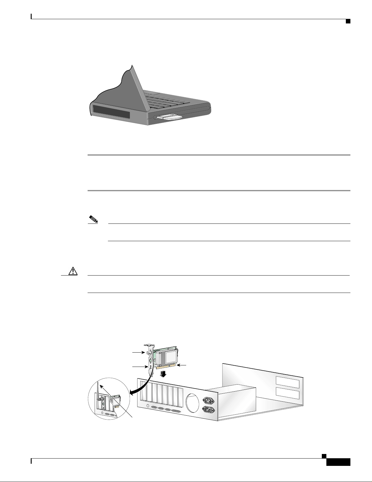
Figure 8-1 Inserting a PC Card or PC-Cardbus Card into a Computing Device
Inserting and Removing a Client Adapter
BETA DRAFT - CISCO CONFIDENTIAL
Step 4
Go to the “Installing the Driver” section on page 3-3 to install the driver for your computer’s operating
system.
Inserting a PCI Card
Step 1 Turn off the PC an d al l i ts c om pon en ts.
Step 2 Remove th e co mpu ter c over.
Note On most Pentium PCs, PCI expansion slots are white. Refe r to your PC
Step 3 Remove the scr ew from the top of th e C PU ba ck p an el a bove an emp ty PCI expansi on sl ot. T his s cr ew
holds the metal bracket on the back panel.
Caution Static electricit y can da mage your PC I c ard. B efo re removin g th e ad ap ter from t he
anti-static packa ging, d isch arge stat ic by touc hing a meta l pa rt of a gr oun de d PC .
Step 4 Examine the PCI card. The antenna connector and the LEDs face out of your computer and are visible
when you put the cover back on. The bottom ed ge of th e card is th e conne ctor you will inse rt into an
empty expansion slot in your comp uter. See Figure 8-2.
documentation for slot identification.
OL-1394-03
Figure 8-2 Inserting a PCI Card into a PC
Antenna
connector
LEDs
Standard 2 dBi
dipole antenna
Cisco Aironet Wireless LAN Client Adapters Installation and Configuration Guide for Windows
Card edge
connector
47521
8-3
Page 4

Inserting and Removing a Cli ent Adapter
BETA DRAFT - CISCO CONFIDENTIAL
Step 5 Tilt the card to allow th e antenna connec tor and LEDs to slip through the open ing in the CPU back panel.
Step 6 Press the card into the empty slot until the connector is firmly seated.
Caution Do not force the ca rd into t he expansi on slot a s thi s c ould dam age bot h t he c ard an d th e
slot. If the card does not insert eas ily, remove it and reinsert it.
Step 7 Reinstal l the scr ew on the CPU back panel and replace th e comp uter cover.
Step 8 Attach the 2-dBi antenna to the card’s antenna connector until it is finger-tight. Do not overtighten.
Step 9 For optimal reception, position the antenna so it is straight up.
Step 10 Boot up your PC.
Removing a Client Adapter
Follow the instructions in one of the sections below to remove a PC card, PC-Cardbus card, or PCI card
from a computing device, when nece ssary.
Chapter8 Routine Procedures
Removing a PC Card or PC-Cardbus Card
To remove a PC card or PC-Cardbus card after it is successfully installed and configured (such as when
your laptop is to be tran spor ted) , comp l etely shut down your comp ut er and pul l the card direc tl y out of
the PC card slot or Card bus slot. Wh en the ca rd is r einse r ted an d th e comp ut er i s reboo ted, y our
connection to t he n etwor k shou ld b e re -est ab lished .
Removing a PCI Card
Because PCI client adapters are installed inside desktop compu ters, which are not designed for portable
use, you should have little reason to remove the adapter. However, instructions are provided below in
case you ever need to remove your PCI card.
Step 1 Comple tely shut down your compu ter.
Step 2 Discon nect the c lient ada pter’s antenn a.
Step 3 Remove th e co mpu ter c over.
Step 4 Remove the screw from the top of the CPU back panel above the PCI expansion slot that holds your client
adapter.
Step 5 Pull up firmly on the client adapter to release it from the slot and carefully tilt the adapter to allow it to
clear the openi ng in the CPU ba ck pane l.
Step 6 Reinstal l the scr ew on the CPU back panel and replace th e comp uter cover.
8-4
Cisco Aironet Wireless LAN Client Adapters Installation and Configuration Guide for Windows
OL-1394-03
Page 5

Chapter 8 Routine Procedures
BETA DRAFT - CISCO CONFIDENTIAL
Upgrading the Firmware
The client adapter is shipped with the firmware installed in its Flash memory; however, a more recent
version of the firmware may be available from Cisco.com. Cisc o recomme nds using th e most curr ent
version of radio firmware. Follow the instructions in this section to determine the version of your client
adapter’s firmware and to upgrade it if a more recent version is available from Cisco.com.
Determining the Firmware Version
Follow the instructions in this section to determine if you need to upgrade the client adapter ’s firmware.
Step 1 To determine the version of firmware that your client adapter is currently using, open ACU; then click
the Status icon or select Status from the Commands drop-down menu. The Status screen displa ys the
current version of your ada pter’s firmware i n the Fir mwa re Version field.
Step 2 To determine the latest firmware version available on Cisco.com, follow the steps below:
a. Use your computer’s web browser to access the following URL:
http://www.cisco.com/public/sw-center/sw-wireless.shtml
Upgrading th e Firm war e
b. Locate the section for client adapter firmware.
c. Click the link for your client adapter’s series (for example, 350 Series).
d. Locate the firmware for your client adapter type and find the one with the greatest release number.
This is the latest available version on Cisco.com.
Note The firmware for PC, LM, and PCI cards is labeled PCM-LMC-PCI, th e firmware for
mini PCI cards is labeled mini PCI or MPI, and the firmware for PC-C ar dbus ca rds i s
labeled CB.
Note In order to use LEAP authentication, your client adapter and access point firmware must
have matching 802.1X draft standards. That is, if the access point uses draft 8 firm war e
(prior to 11.06) or has draft 8 selected, the client adapter must use draft 8 firmware (prior
to 4.25.x). Similarly, if the access point uses draft 10 firmware (11. 06 or later) and has
draft 10 selected, the client adapter must use draft 10 firmware (4.25.x or later). Mini PCI
card firmware and PC-Cardbus card firmware were first released at draft 10.
Note In order to us e EA P-T LS or E A P-MD5 a uthe nti cat ion wi th Windows XP, your client
adapter and acces s point mu st use 802.1 X draf t standa rd 10 firmware.
Step 3 If the firmware available from Cisco.com has a higher number than the firmware currently installed in
your client adapter , follow th e instructions in the “Loading New Firmware” section below to upgrade the
firmware.
OL-1394-03
Cisco Aironet Wireless LAN Client Adapters Installation and Configuration Guide for Windows
8-5
Page 6

Upgrading the Firmware
BETA DRAFT - CISCO CONFIDENTIAL
Loading New Firmware
Caution If a power failure occurs while you are loading new firmware, your client adapter may
become inoperable. If this occurs, follow the instructions in the “Technical Assistance
Center” section of the Preface to contact TAC for assistance.
Follow the instructions below to load new firmware into your client adapter.
Step 1 Use you r compu ter’s web browser to access the following URL:
http://www.cisco.com/public/sw-center/sw-wireless.shtml
Step 2 Locate the section for client adapter firmware.
Step 3 Click the link for your client adapter’s series (for example, 350 Series).
Step 4 Click the latest radio firmware file for your client adapter type.
Note The firmware for PC, LM, and PCI cards is labeled PCM-LMC-PCI, the firmware for mi ni
Chapter8 Routine Procedures
PCI cards is labeled mini PCI or MPI, and the firmware for PC-Cardbus cards is labeled CB.
Note If your wireless network uses L EAP authenticatio n, remember to select radio firmw are of the
same draft standard as the acc ess points to which your cl ie nt adapt er wil l be authe ntica ting.
Mini PCI card firmware and PC -Car dbus card firmware w ere first re lease d at draft 10.
Note If your wireless network uses EAP-TLS or EAP-MD5 authentica tion, remem ber to sele ct
draft 10 of the ra dio firm ware.
Step 5 Read and accept the terms and conditions of the Software License Agreement.
Step 6 Select the firmware file to download it.
Step 7 Save the file to a floppy disk or to your computer’s hard drive.
Step 8 Locate the file using Windows Explorer, double-click it, and extract the image file to a folder.
Step 9 Make sure the c lient ada pter i s installed i n your comput er and is op erat ional.
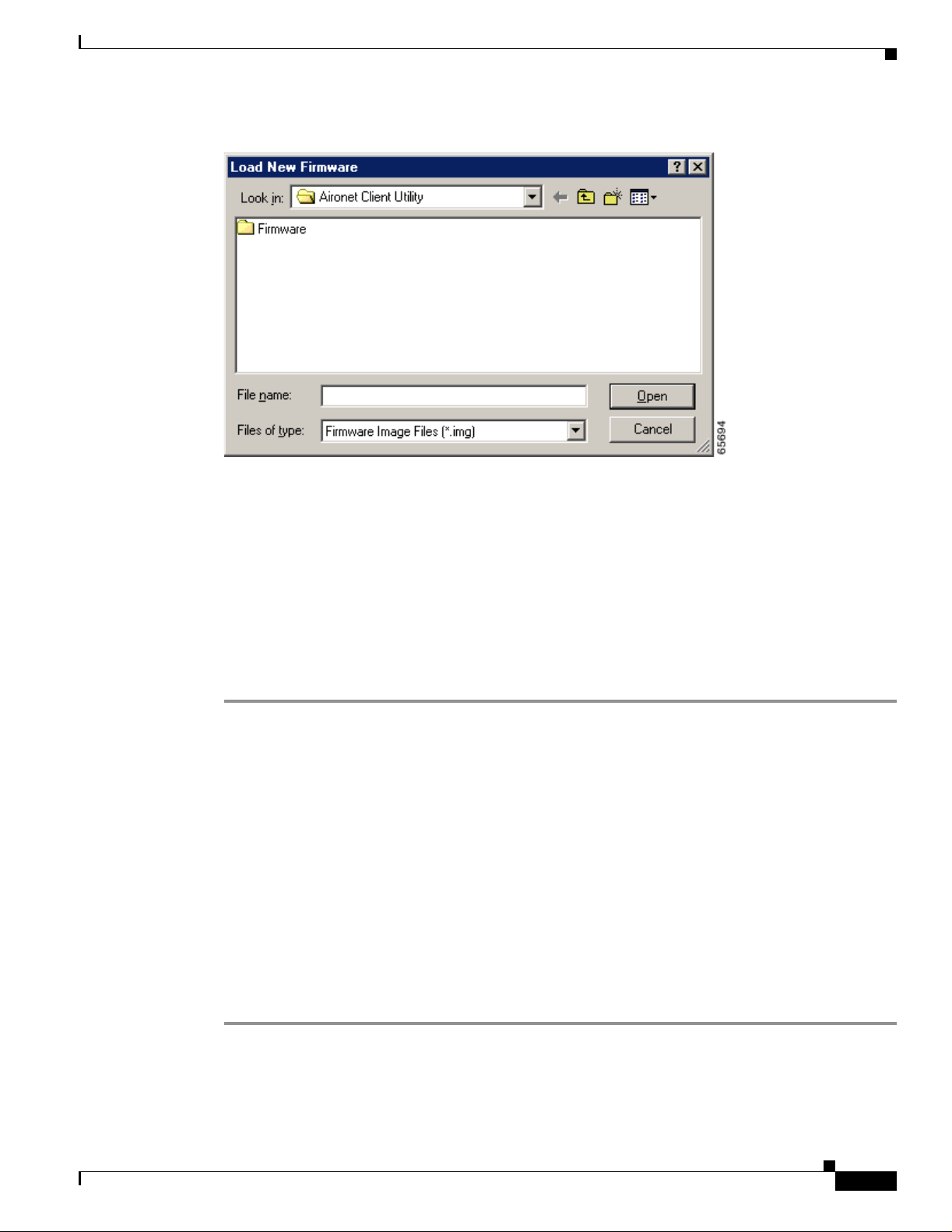
Step 10 Open ACU; then click the Load Firmware icon or select L oad New Firmware from the Commands
drop-down menu. The Open window appear s (see Figure 8-3).
8-6
Cisco Aironet Wireless LAN Client Adapters Installation and Configuration Guide for Windows
OL-1394-03
Page 7
Chapter 8 Routine Procedures
Figure 8-3 Open Window
Driver Procedures
BETA DRAFT - CISCO CONFIDENTIAL
Step 11 Find the location of the new firmware in the Look in box. The default location is InstallPath\Firmware,
where InstallPath is the directory that ACU was installed in.
Step 12 Click the firmware image file (*.img) so that it appears in the File name box at the bottom of the Open
window.
Step 13 Click the Open button. A progress bar displays while the selected image is loaded into the client adapter’s
Flash memory.
Step 14 Click OK when the “Firmware Upgrade Complete!” message appears. The OK button cannot be selected
until t he p r oc e s s i s c o mp l e te or an error oc cu r s. If an error occurs, refer to the “Error Messages” section in
Chapter 9.
Driver Procedures
This section inc lude s the fo llowing pr oc edur es:
• Determining the driver version, see below
• Upgrading the driver, see 8-8
• Uninstalling the driver, see 8-13
Determining the Driver Version
OL-1394-03
Follow the instructions in this section to determine if you need to upgrade the client adapter’s driver.
Step 1 To determine the version of the driver that yo ur cl ient a da pte r is c urr en tly using, open ACU; then cli c k
the Status icon or select Status from the Commands drop-down menu. The Status screen displa ys the
current version of your ada pter’s driver in the ND IS Driver Version field.
Cisco Aironet Wireless LAN Client Adapters Installation and Configuration Guide for Windows
8-7
Page 8

Driver Procedures
Step 2 To determine the latest driver version available on Cisco.com, follow the steps below:
Step 3 If the driver available from Cisco.com has a higher number than the driver currently being used by your
Chapter8 Routine Procedures
BETA DRAFT - CISCO CONFIDENTIAL
a. Use your computer’s web browser to access the following URL:
http://www.cisco.com/public/sw-center/sw-wireless.shtml
b. Locate the section for client adapter drivers and utilities.
c. Click the link for individual Windows files.
d. Locate the drivers for your specific operating system and clie nt adapte r type and find the one with
the greatest release number. This is the latest available version on Cisco.com.
Note The drivers for PC, LM, and PCI cards are labeled PCM-LMC-PCI; the drivers for mini
PCI cards and PC-Cardbus cards are labeled MPI-CB.
client adapter, follow the instructions in the “Upgrading the Driver” section on page 8-8 t o upgr ad e the
driver.
Note If the 6.10 driver is inst alle d o n you r Windows 95, 98, NT, or 2000 compu ter, you mus t
remove this driver befo r e yo u can in stall a m or e r ece n t dr iver. Refer to the “Uninstallin g the
6.10 Driver” section on page 8-13 for instructions.
Upgrading the Driver
Follow the instructions in this section to upgrade your client adapter’s driver to a more recent version.
Use Table 8-1 to quickly locate the instructions to upgrade the driver for your specific operating system.
Table 8-1 Updating the Driver Instructions
Operating System Page Number
Windows 95 8-8
Windows 98 8-8
Windows NT 8-9
Windows 2000 8-10
Windows Millennium Edition (Me) 8-11
Windows XP 8-12
Upgrading the Driver for Windows 95 and 98
Step 1 Use you r compu ter’s web browser to access the following URL:
http://www.cisco.com/public/sw-center/sw-wireless.shtml
Step 2 Locate the section for client adapter drivers and utilities.
8-8
Step 3 Click the link for individual Windows files.
Cisco Aironet Wireless LAN Client Adapters Installation and Configuration Guide for Windows
OL-1394-03
Page 9

Chapter 8 Routine Procedures
Step 4 Select th e latest driver file for Windows 95 or Windows 98 and your client adapter type.
Note The drivers for PC, LM, an d PC I ca rd s ar e la beled PCM-LMC-PCI; the dri vers for mini PCI
Step 5 Read and accept the terms and conditions of the Software License Agreement.
Step 6 Select the driver file to download it.
Step 7 Save the file to a floppy disk or to your computer’s hard drive.
Step 8 Locate the file using Windows Explorer, double-click it, and extract its files to a folder.
Step 9 Make sure your client adapter is installed in your computer.
Step 10 Double-click My Comput er, Control Panel, and System.
Step 11 Click the Device Manager tab.
Step 12 Double-click Network Adapters.
Step 13 Select the Cisco Systems wireless LAN adapter.
Step 14 Click Properties, the Driver tab, and the Change Driver or Update Driver butt o n .
Driver Procedures
BETA DRAFT - CISCO CONFIDENTIAL
cards and PC-Cardbus cards are labeled MPI-CB.
Step 15 The Update Device Driver Wizard window appears. Cli ck Next.
Step 16 Select Search for a better driver than the one your device is using now (Recommended) and click
Next.
Step 17 Select the location of the new dri v er (flo ppy disk dr i v e or specify a loca tion), desele ct the other o ptions,
enter the full path to where you extracted the files, and click Next.
Step 18 A message appears indicating that the system is ready to install the new driver. Click Next and Finish.
The driver upgrade is complete, and the old driver is overwritten by the new one.
Upgrading the Driver for Windows NT
Step 1 Use you r compu ter’s web browser to access the following URL:
http://www.cisco.com/public/sw-center/sw-wireless.shtml
Step 2 Locate the section for client adapter drivers and utilities.
Step 3 Click the link for individual Windows files.
Step 4 Select the latest driver file for Windows NT and your client adapter type.
Note The drivers for PC, LM, an d PC I ca rd s ar e la beled PCM-LMC-PCI; the dri vers for mini PCI
cards and PC-Cardbus cards are labeled MPI-CB.
OL-1394-03
Step 5 Read and accept the terms and conditions of the Software License Agreement.
Step 6 Select the driver file to download it.
Step 7 Save the file to a floppy disk or to your computer’s hard drive.
Step 8 Locate the file using Windows Explorer, double-click it, and extract its files to a folder.
Step 9 Make sure your client adapter is installed in your computer.
Cisco Aironet Wireless LAN Client Adapters Installation and Configuration Guide for Windows
8-9
Page 10

Driver Procedures
BETA DRAFT - CISCO CONFIDENTIAL
Step 10 Double-click My Comput er, Control Panel, Network, and Adapters.
Step 11 Select the Cisco Systems wireless LAN adapter.
Step 12 Click the Update button.
Step 13 In the Windows NT Setup window, enter the path to where you extracted the files and click Continue.
Step 14 Follow the instructions on the screen to complete the upgrade process.
Upgrading the Driver for Windows 2000
Step 1 Use you r compu ter’s web browser to access the following URL:
http://www.cisco.com/public/sw-center/sw-wireless.shtml
Step 2 Locate the section for client adapter drivers and utilities.
Step 3 Click the link for individual Windows files.
Step 4 Select the latest driver file for Windows 2000 and your client adapter type.
Chapter8 Routine Procedures
Note The drivers for PC, LM, an d PCI cards are labeled PCM-LMC-PCI; the driver s for m ini PCI
cards and PC-Cardbus cards are labeled MPI-CB.
Step 5 Read and accept the terms and conditions of the Software License Agreement.
Step 6 Select the driver file to download it.
Step 7 Save the file to a floppy disk or to your computer’s hard drive.
Step 8 Locate the file using Windows Explorer, double-click it, and extract its files to a folder.
Step 9 Make sure your client adapter is installed in your computer.
Step 10 Double-click My Comput er, Control Panel, and System.
Step 11 Click the Hardware tab and Device Manager.
Step 12 Double-click Network Adapters and the Cisco Systems wireless LAN adapter.
Step 13 Click the Driver tab.
Step 14 Click the Update Driver butto n .
Step 15 The Update Device Driver Wizard window appears. Cli ck Next.
Step 16 Select Display a list of the known drivers for this device so that I can choose a specific driver and
click Next.
Step 17 Click Have Disk.
Step 18 Enter or browse to the path where you extracted the files and click OK.
Step 19 A message appears indicating that the system is ready to install the new driver. Click Next and Finish.
The driver upgrade is complete, and the old driver is overwritten by the new one.
8-10
Cisco Aironet Wireless LAN Client Adapters Installation and Configuration Guide for Windows
OL-1394-03
Page 11

Chapter 8 Routine Procedures
BETA DRAFT - CISCO CONFIDENTIAL
Upgrading the Driver for Windows Me
Step 1 Use you r compu ter’s web browser to access the following URL:
http://www.cisco.com/public/sw-center/sw-wireless.shtml
Step 2 Locate the section for client adapter drivers and utilities.
Step 3 Click the link for individual Windows files.
Step 4 Select the latest driver file for Windows Me and your client adapter type.
Note The drivers for PC, LM, an d PC I ca rd s ar e la beled PCM-LMC-PCI; the dri vers for mini PCI
cards and PC-Cardbus cards are labeled MPI-CB.
Step 5 Read and accept the terms and conditions of the Software License Agreement.
Step 6 Select the driver file to download it.
Step 7 Save the file to a floppy disk or to your computer’s hard drive.
Step 8 Locate the file using Windows Explorer, double-click it, and extract its files to a folder.
Driver Procedures
Step 9 Make sure your client adapter is installed in your computer.
Step 10 Double-click My Comput er, Control Panel, and System.
Step 11 Click the Device Manager tab.
Step 12 Double-click Network Adapters.
Step 13 Select the Cisco Systems wireless LAN adapter.
Step 14 Click Properties, the Driver tab, and the Update Driver button. The Update Device Driver Wizard
window appears.
Step 15 Select Specify the location of the driver (Advanced) and click Next.
Step 16 Select Search for a better driver than the one your device is using now (Recommended).
Step 17 Select the Specify a location checkbox, deselect the other options, enter the path to where you extracted
the files, and click Next.
Step 18 A message app ears i ndic ating that Windows has found a n upda ted d river. Select The updated driver
(Recommended) and click Next.
Step 19 A message appears indicating that the system is ready to install the new driver. Click Next and Finish.
Step 20 If you are prompte d to res tart you r compu ter, click Yes.
The driver upgrade is complete, and the old driver is overwritten by the new one.
OL-1394-03
Cisco Aironet Wireless LAN Client Adapters Installation and Configuration Guide for Windows
8-11
Page 12

Driver Procedures
BETA DRAFT - CISCO CONFIDENTIAL
Upgrading the Driver for Windows XP
Note These instructions assume you are using Windows XP’s c lassic v iew rather than its c ategory
view.
Step 1 Use you r compu ter’s web browser to access the following URL:
http://www.cisco.com/public/sw-center/sw-wireless.shtml
Step 2 Locate the section for client adapter drivers and utilities.
Step 3 Click the link for individual Windows files.
Step 4 Select the latest driver file for Windows XP and your client adapter type.
Note The drivers for PC, LM, an d PCI cards are labeled PCM-LMC-PCI; the driver s for m ini PCI
cards and PC-Cardbus cards are labeled MPI-CB.
Step 5 Read and accept the terms and conditions of the Software License Agreement.
Chapter8 Routine Procedures
Step 6 Select the driver file to download it.
Step 7 Save the file to a floppy disk or to your computer’s hard drive.
Step 8 Locate the file using Windows Explorer, double-click it, and extract its files to a folder.
Step 9 Make sure your client adapter is installed in your computer.
Step 10 Double-click My Comput er, Control Panel, and System.
Step 11 Click the Hardware tab and Device Manager.
Step 12 Double-click Network Adapters and Cisco Systems 3x0 Series Wireless LAN Adapter.
Step 13 Click the Driver tab and the Update Driver button. The Welcome to the Hardware Update Wizard
screen appears.
Step 14 Select the Install from a list or specific location (Advanced) option and click Next.
Step 15 When prompted to choose your search and installation options, select Don’t search. I will choose the
driver to install and click Next.
Step 16 When prompted to select a network adapter to i nstall, click the Ha ve Disk bu tton. The In stall From Disk
screen appears.
Step 17 Click the Browse button, browse to the location where you extracted the files, and click Open. The
installation wizard finds the driver file (netx500.inf). Click OK on the Install From Disk screen.
Step 18 The Select Network Adapte r screen reappear s. Select the Cisc o Systems wi reless LA N adapte r and click
Next.
Step 19 The install atio n w iz ard c op ies th e driver files from t he f loppy d i sk or c om pute r’s hard drive. When the
installation is complete, click Finish.
The driver upgrade is complete, and the old driver is overwritten by the new one.
8-12
Cisco Aironet Wireless LAN Client Adapters Installation and Configuration Guide for Windows
OL-1394-03
Page 13

Chapter 8 Routine Procedures
BETA DRAFT - CISCO CONFIDENTIAL
Uninstalling the Driver
This section provides instructions for uninstalling a client adapter driver from your computer. Two
examples of when you m ay ne ed to un inst all a driver are li sted be low:
• If you are running Windows 95, 98, N T, or 2000 and a Cisc o Aironet client adapter was previously
installed on your computer with the 6.10 driver, you must uninstall this driver before you can install
a more recent driver, such as the one provided on the CD that shipped with your client adapter.
• If you experience difficulty while installing t he driver for your computer ’s operating system, you
may want to abort the installation procedure and start over. However, before you attempt to install
the driver again, you mu st first u nin sta ll any p ar t of the d river that you may have alrea dy inst alle d.
Table 8-2 enables yo u to qu ick ly l oca te the inst ru ctions fo r uninst all ing a driver for your spe ci fic
operating system.
Table 8-2 Locating Driver Uninstall Instructions
Operating S ystem 6.10 Driver Driver Other Tha n 6.1 0
Windows 95 page 8-13 page 8-16
Windows 98 page 8-13 page 8-16
Windows NT page 8-14 page 8-17
Windows 2000 page 8-15 page 8-17
Windows Millennium (Me) Not applicable page 8-16
Windows XP Not applicable page 8-18
Driver Procedures
Uninstalling the 6.10 Driver
To uninstall the 6.10 dr iver, follow the instructio ns that ap ply to y our c omp ute r’s operating system.
Uninstalling the 6.10 Driver for Windows 95 and 98
Step 1 Make sure th e previous clien t adapter is in your com puter an d the compu ter is booted up.
Step 2 Right-cl ic k th e WepStat icon in the system tra y on your d eskt op. T his ic on l ook s like two conn ec ted
computers.
Step 3 Click Terminate.
Step 4 Insert the CD that contains the 6.10 driver into your computer’s CD-ROM drive.
Step 5 Open Windows Explorer and find the \Utilities\RmWep directory on your computer’s CD-ROM drive.
Step 6 Double-click the RmWep.exe file.
Step 7 Minimize Windows Explorer.
Step 8 Double-c li ck My Computer, Control Panel, and Network.
Step 9 In the Network window, select the Cisco Systems wireless LAN adapter.
Step 10 Click Remove and OK.
Step 11 When prompted to re start your co mput er, click No.
Step 12 Maximize Windows Explorer.
OL-1394-03
Cisco Aironet Wireless LAN Client Adapters Installation and Configuration Guide for Windows
8-13
Page 14

Driver Procedures
Step 13 Click View, Options or Fol d e r O p tions , an d View. Under Hidden files, ma ke s ure Show all files is
Step 14 Find your computer’s operating system in the following table, go to the path listed, and delete the file
Step 15 Remove the CD from y our comp ut er’s CD-ROM drive.
Step 16 Shut down your computer.
Step 17 Remove the client adapter.
Chapter8 Routine Procedures
BETA DRAFT - CISCO CONFIDENTIAL
selected, make sure the Hide file extensions for known file types checkbox is deselected, and click
OK.
indicated.
Operating System Location of File File to be Deleted
Windows 95 C:\Windows\Inf pc4800.inf
Windows 98 C:\Windows\Inf or
C:\Windows\Inf\Other
pc4800.inf or
aironetnetx500 .inf
Uninstalling the 6.10 Driver for Win dows NT
Step 1 Make sure th e previous clien t adapter is in your com puter an d the compu ter is booted up.
Step 2 Right-cl ic k th e WepStat icon in the system tra y on your d eskt op. T his ic on l ook s like two conn ec ted
computers.
Step 3 Click Terminate.
Step 4 Insert the CD that contains the 6.10 driver into your computer’s CD-ROM drive.
Step 5 Open Windows Explorer and find the \Utilities\RmWep directory on your computer’s CD-ROM drive.
Step 6 Double-click the RmWep.exe file.
Step 7 Close Windows Explorer.
Step 8 Double-c li ck My Computer, Control Panel, and Network.
Step 9 In the N et work w indow, click the Adapters tab.
Step 10 Select the Cisco Systems wireless LAN adapter.
Step 11 Click Remove.
Step 12 When asked if you wish to co ntinue , click Yes and Close.
Step 13 When prompted to re start your co mput er, click No.
Step 14 Remove the CD from y our comp ut er’s CD-ROM drive.
Step 15 Shut down your computer.
8-14
Step 16 Remove the client adapter.
Cisco Aironet Wireless LAN Client Adapters Installation and Configuration Guide for Windows
OL-1394-03
Page 15

Chapter 8 Routine Procedures
BETA DRAFT - CISCO CONFIDENTIAL
Uninstalling the 6.10 Driver for Windows 2000
Step 1 Make sure th e previous clien t adapter is in your com puter an d the compu ter is booted up.
Step 2 Right-cl ic k th e WepStat icon in the system tra y on your d eskt op. T his ic on l ook s like two conn ec ted
computers.
Step 3 Click Terminate.
Step 4 Insert the CD that contains the 6.10 driver into your computer’s CD-ROM drive.
Step 5 Open Windows Explorer.
Step 6 Click Tools, Folder Opt i on s , and View.
Step 7 Under H idden files and fo lder s, make sure Show hidden files and folders is selected, make sure the
Hide file extensions for known file types checkbox is deselected, and click OK.
Step 8 Find the \Utilities\RmWep directory on your computer’s CD-ROM drive.
Step 9 Double-click the RmWep.exe file.
Step 10 Go to C:\Windows\Inf an d doubl e- clic k t he oe mx.inf and oem x.pnf files, where x equals a numera l, to
open them.
Step 11 Delete the oemx.inf and oemx.pnf files that are labeled Aironet and are for a wireless LAN adapter.
Driver Procedures
Step 12 Remove the CD from y our comp ut er’s CD-ROM drive.
Step 13 If you are prompte d to res tart you r compu ter, click Yes.
Step 14 When the computer restarts, double-click My Computer, Control Panel, and Add/Remove
Hardware.
Step 15 In the Ad d /Rem ove Ha rdware Wizard w indow, click Next.
Step 16 Click Uninstall/Unplug a device. Click Next.
Step 17 Click Uninstall a device. Click Next.
Step 18 From the Devices list, select the Cisco Systems wireless LAN adapter. Click Next.
Step 19 Click Yes, I want to uninstall this device. Click Next.
Step 20 Click Finish.
Step 21 Shut down your computer.
Step 22 Remove the client adapter.
OL-1394-03
Cisco Aironet Wireless LAN Client Adapters Installation and Configuration Guide for Windows
8-15
Page 16

Driver Procedures
BETA DRAFT - CISCO CONFIDENTIAL
Uninstalling a Driver Other Than the 6.10 Driver
To uninstall a driver other tha n the 6. 10 driver, follow the instruc tions t h at a pp ly t o yo ur co mp uter ’s
operating system.
Note When you uninstall the driver, any saved profiles are lost.
Uninstalling the Driver for Win dows 95, 98, and Me
Note This procedure does not uninstall the driver that was bundled with Windows Me. It uninstalls only
drivers to which you have upgraded. When you follow the steps below to uninstall an upgraded driver
and then eject and reinsert the card, Windows Me finds the original driver and reinstalls it
automatically.
Step 1 Double-c li ck My Computer, Control Panel, and Network.
Step 2 In the Network window, select the Cisco Systems wireless LAN adapter.
Chapter8 Routine Procedures
Step 3 Click Remove and OK.
Step 4 When promp ted to re start your co mputer, click No.
Step 5 Open Windows Explorer.
Step 6 If your computer’s operating system is Windows 95 or 98, click View, Options or Folder Options, and
View. Under Hidden files, make sure Show all files is selected and click OK.
Step 7 Find your com puter’s operating system in the following table, go to the path listed, and delete the file
indicated.
Operating System Location of File File to be Deleted
Windows 98 C:\Windows\Inf or
C:\Windows\Inf\Other
pc4800.inf,
aironetnetx500 .inf, or
cisconetx500.inf
Windows Me C:\Windows\Inf\Other ai ro netn etx 500 .i nf or
cisconetx500.inf
Step 8 Find your com puter’s operating system i n the following tabl e and dele te any pcx50*.sys files fro m the
path indicated.
Operating System Location of pcx50 *.s ys Files
Windows 95 C:\Windows\System\pcx50*.sys
Windows 98 C:\Windows\System\pcx50*.sys
Windows Me C :\Windows\System32\Drivers\pcx50*.sys
8-16
Step 9 Rest art yo ur compu ter.
Cisco Aironet Wireless LAN Client Adapters Installation and Configuration Guide for Windows
OL-1394-03
Page 17

Chapter 8 Routine Procedures
BETA DRAFT - CISCO CONFIDENTIAL
Uninstalling the Driver for Win dows NT
Step 1 Double-c li ck My Computer, Control Panel, and Network.
Step 2 In the N et work w indow, click the Adapters tab.
Step 3 Select the Cisco Systems wireless LAN adapter.
Step 4 Click Remove.
Step 5 When as ked if you wish to co ntinue, c lick Yes and Close.
Step 6 When promp ted to re start your co mputer, click Yes.
Uninstalling the Driver for Windows 2000
Step 1 Make sure the client adapter is installed in your computer. Otherwise, Windows cannot find the adapter
to remove it.
Step 2 Double-c li ck My Computer, Control Panel, and Add/Remove Hardware.
Driver Procedures
Step 3 In th e A dd / Rem ove Hardwa re Wizard w in dow, click Next.
Step 4 Click Uninstall/Unplug a device. Click Next.
Step 5 Click Uninstall a device. Click Next.
Step 6 From the Devices list, select the Cisco Systems wireless LAN adapter. Click Next.
Step 7 Click Yes, I want to uninstall this device. Click Next.
Step 8 Click Finish.
Step 9 Open Windows Explorer.
Step 10 Click Tools, Folder Op t io n s , and View.
Step 11 Under Hidden files and folder s, make sure Show hidden files and folders is selected. Click OK.
Step 12 Go to C:\Windows\Inf an d doubl e- clic k t he oe mx.inf and oem x.pnf files, where x equals a numera l, to
open them.
Step 13 Delete the oemx.inf and oemx.pnf files that are labeled Cisco and are for a wireless LAN adapter.
Step 14 Go to C:\Windows\System32\Drivers and delete any pcx500*.sys files.
Step 15 Shut down your computer.
Step 16 Remove the client adapter.
Step 17 Turn your computer b ac k on.
OL-1394-03
Cisco Aironet Wireless LAN Client Adapters Installation and Configuration Guide for Windows
8-17
Page 18

ACU Procedures
BETA DRAFT - CISCO CONFIDENTIAL
Uninstalling the Driver fo r Windows XP
Note This procedure will not uninstall the driver that was bundled with Windows XP. It will
uninstall only d rivers to whic h you have upgr aded . Whe n you f oll ow the ste ps be low to
uninstall an upgraded driver and then ejec t and r einser t th e c ard, Windows finds the original
driver and rein stal ls it au tom at ica lly.
Note These instructions assume you are using Windows XP’s c lassic v iew rather than its c ategory
view.
Step 1 Double-c li ck My Computer, Control Panel, and System.
Step 2 Click the Hardware tab and Device Manager.
Step 3 Double-c li ck Network Adapters and Cisco Systems 3x0 Se ries Wireless LAN Adapter.
Step 4 Click the Driver tab and the Uninstall button.
Step 5 A warning ap pe ar s indi cat ing tha t yo u are a bout t o unins tal l the clie nt ada pte r fr om your syst em. Cl ick
OK.
Chapter8 Routine Procedures
ACU Procedures
This section provides instruc tions for th e following proced ures:
• Opening ACU, see below
• Exiting ACU, see 8-19
• Modifying ACU installation settings, see 8-19
• Determining the version of ACU, see 8-21
• Upgrading ACU, see 8-22
• Uninstalling ACU, see 8-24
• Deleting the ACU icon from the desktop, see 8-25
Opening ACU
To open ACU, perform one of the following:
• Double-click the Aironet Client Utility (ACU) icon on your desktop.
• Select Aironet Client Utility (ACU) from the folder in the Windows Start Menu that you chose
during installation [the default location is Start > Program Files > Cisco Aironet > Aironet Client
Utility (ACU)].
• Double-click My Computer > Control Panel > Aironet Client Utility.
8-18
Cisco Aironet Wireless LAN Client Adapters Installation and Configuration Guide for Windows
OL-1394-03
Page 19
Chapter 8 Routine Procedures
Exiting ACU
ACU Procedures
BETA DRAFT - CISCO CONFIDENTIAL
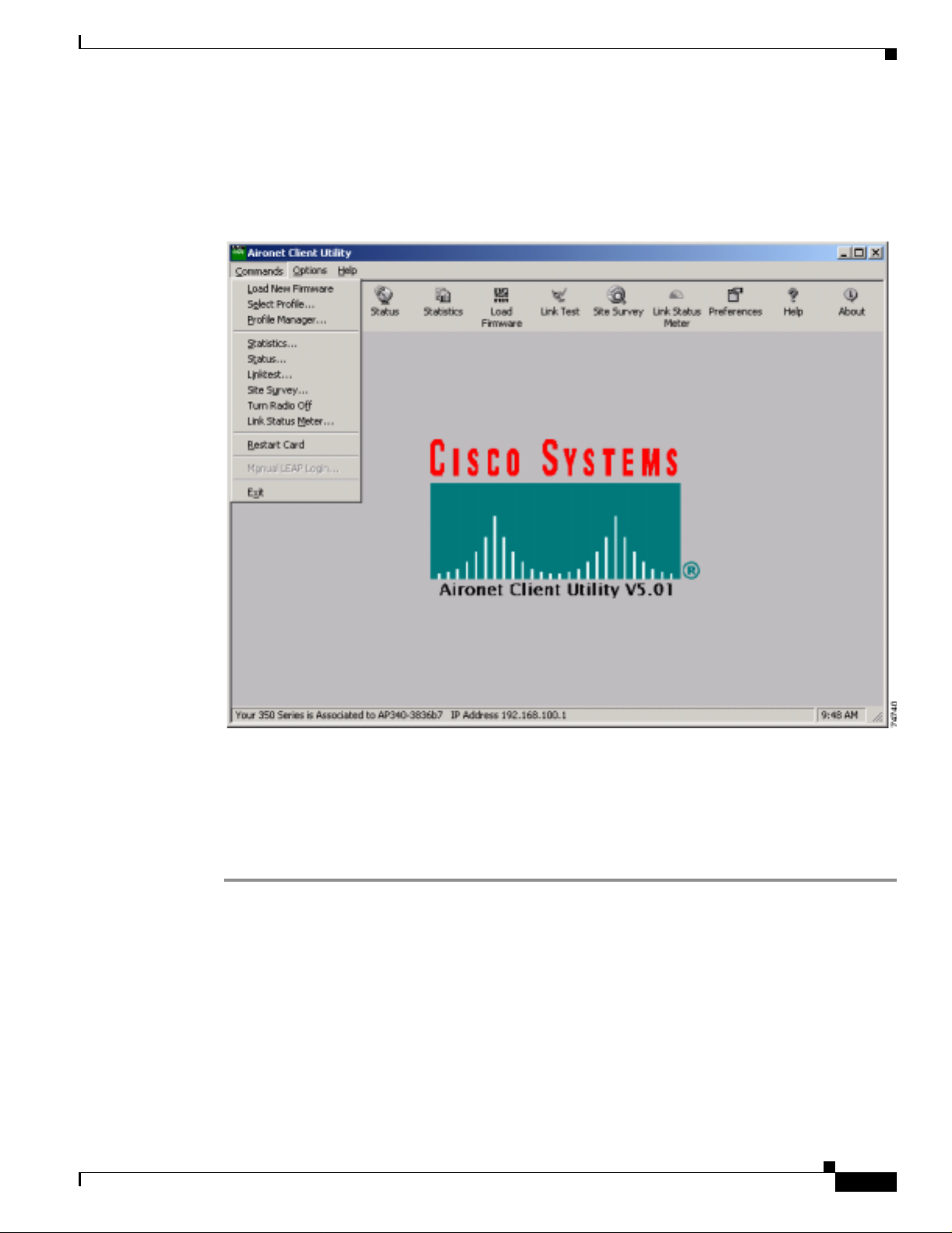
To exit ACU, select Exit from the Commands drop-down menu (see Figure 8-4).
Figure 8-4 Commands Drop-Down Menu
Modifying ACU Installation Settings
Follow the steps below if you need to change any of the settings selected during ACU installation (for
example, selecting L EAP o r th e loc ation of the ACU prog ram files).
Step 1 Close any Windows programs t hat are run ni ng.
Step 2 Select Start > Run, browse or enter the path to the installed ACU files (the default location is
C:\Program Files\Cisco Airo ne t\setup. exe), and click OK. The Welcome screen for the Aironet Client
Utility setup maintenance program appears.
Step 3 Select Modify and click Next. The installation goes through the same sequence of screens that appeared
during the initial installation to allo w you to select or deselect v arious options . The follo wing steps wal k
you through the rema ini ng scre en s.
Cisco Aironet Wireless LAN Client Adapters Installation and Configuration Guide for Windows
OL-1394-03
8-19
Page 20

ACU Procedures
Step 4 In the Select Options screen, select as many of the following options as desired and click Next:
Chapter8 Routine Procedures
BETA DRAFT - CISCO CONFIDENTIAL
Option Description
LEAP Enables you to create a profile in ACU that uses LEAP authentication.
If this option is no t sele cte d n ow and you late r want to use LE A P, you
must run this installation program ag a in, se lect Modify, and sele ct thi s
option.
Note Refer to Chapter 5 for information on using LEAP.
Note If you sel ect LEA P on a Windows 95, 98, or 9 8 SE device,
Microsoft hot fixes are installed during ACU installati on to fix
two prob lems r elated to the us e of LE AP. Refer to Chapter 9 for
more information on the hot fixes.
Note If you select LEAP on a Windows XP device, you cannot use
Wind o ws X P’s fast user switching feature.
Allow Saved LEAP User
Name and Password
Enables you to create a profile in ACU that uses a saved (rather than
temporary) usernam e an d p assword fo r LE AP a ut hent icat ion. W hen
such a profile is used , the saved userna me and p assword ar e use d to
start the LEAP authentic ation proces s, and you ar e not promp ted to
enter them.
Note This option is available only if the LEAP option is selected.
Create ACU Icon on your
Desktop
Allow Non-Administrator
Users to use ACU to modify
profiles
Causes the installation program to add an ACU icon to your computer’s
desktop to provide quick access to the utility.
Enables users without administrative rights to modify profiles in ACU
on computers running Windows NT, 2000, or XP.
Note This opti on is not availabl e fo r Windows 95, 98 , an d Me
because these versions of Windows do not support different
classes of users.
Step 5 In the Ch oose Desti nat ion L oca tio n scr een, perf or m one o f th e foll owing:
• If you want the ACU program files to be installed in the default location (C:\Program Files, if
C:\Program Files is the default Windows program file folder), click Next.
• If you want to specify a different destinat ion locati on for the ACU program files, click Browse,
select a location, and click Next.
Step 6 In the Select Program Folder screen, specify a program folder name for ACU by selecting from the list
of existing folders (the defa ult na m e is Cisc o Airone t) or typi ng in a new folde r n ame ; t hen c li ck Next.
A status screen displays the progress of the installation. Then the Setup Complete screen appears.
Step 7 If your co mputer needs to be re booted , select Yes, I want to restart my computer now or No, I will
restart my computer later and clic k Fin ish .
8-20
Note If you are prompted to reb oot your com pute r, Cisco recommends th at you selec t the Yes, I
want to restart my computer now option.
The client utility installation has been modified.
Cisco Aironet Wireless LAN Client Adapters Installation and Configuration Guide for Windows
OL-1394-03
Page 21
Chapter 8 Routine Procedures
BETA DRAFT - CISCO CONFIDENTIAL
Determining the Version of ACU
Follow the instructions in this section to determine if you need to upgrade ACU.
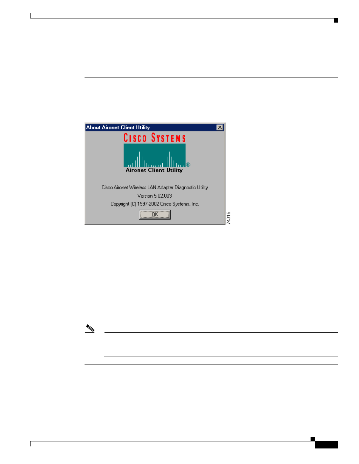
Step 1 To determine the version of ACU that your client adapter is currently using, open ACU; then click the
About icon or select the About Aironet Client Utility option from the Help drop-down menu. The
About Aironet Client Utility screen appears (see Figure 8-5).
Figure 8-5 About Aironet Client Utility Screen
ACU Procedures
Step 2 To determine the latest version of ACU available on Cisco.com, follow the steps below:
a. Use your computer’s web browser to access the following URL:
http://www.cisco.com/public/sw-center/sw-wireless.shtml
b. Locate the section for client adapter drivers and utilities.
c. Click the link for individual Windows files.
d. Locate the ACU files and find the one with the greatest release number. This is the latest available
version on Cisco.com.
Step 3 If the vers ion o f ACU available from Cisco. co m ha s a hig her num be r th an the versio n cur re ntl y be ing
used by your client adapter, follow the instructions in the “Upgrading ACU” section on page 8-22 to
upgrade ACU.
Note If a version of ACU prior to 4.13 is installed on your computer, you must u ninstall it before
you can upgrade t o a more recent version . Refer to the “Uninstalling ACU Ve r sions Prior to
4.13” section o n page 8-24 for instructions.
OL-1394-03
Cisco Aironet Wireless LAN Client Adapters Installation and Configuration Guide for Windows
8-21
Page 22

ACU Procedures
Upgrading ACU
Follow the instructions in this section to upgrade ACU to a more recent version.
Note If you cr ea te pr ofiles u si ng ACU version 5. 0 ( or gr ea ter ), t hese p rofiles ar e saved if you upg ra de t o
a more recent versio n o f ACU.
Step 1 Close any Windows programs t hat are run ni ng.
Step 2 Use the computer’s web browser to access the following URL:
http://www.cisco.com/public/sw-center/sw-wireless.shtml
Step 3 Locate the section for client adapter drivers and utilities.
Step 4 Click the link for individual Windows files.
Step 5 Select the latest ACU file.
Step 6 Read and accept the terms and conditions of the Software License Agreement.
Step 7 Select the ACU file to download it.
Chapter8 Routine Procedures
BETA DRAFT - CISCO CONFIDENTIAL
Step 8 Save the file to your computer’s hard drive.
Step 9 Locate the file using Windows Explorer, double-click it, and extract its files to a folder.
Step 10 Select Start > Run, enter or browse to the path where you extracted the files (for example,
C:\temp\setup.exe), and click OK. The Aironet Client Utility Set up sc ree n an d the I nst allSh ie ld Wizard
appear.
Step 11 When the Welcome screen appears, click Next.
Step 12 In the Select Options screen, select as many of the following options as desired and click Next:
Option Description
LEAP Enables you to create a profile in ACU that uses LEAP authentication.
If this option is no t sele cte d n ow and you late r want to use LE A P, you
must run this installation program ag a in, se lect Modify, and sele ct thi s
option.
Note Refer to Chapter 5 for information on using LEAP.
Note If you sel ect LEA P on a Windows 95, 98, or 9 8 SE device,
Microsoft hot fixes are installed during ACU installati on to fix
two prob lems r elated to the us e of LE AP. Refer to Chapter 9 for
more information on the hot fixes.
Note If you select LEAP on a Windows XP device, you cannot use
Wind o ws X P’s fast user switching feature.
Allow Saved LEAP User
Name and Password
Enables you to create a profile in ACU that uses a saved (rather than
temporary) usernam e an d p assword fo r LE AP a ut hent icat ion. W hen
such a profile is used , the saved userna me and p assword ar e use d to
start the LEAP authentic ation proces s, and you ar e not promp ted to
enter them.
8-22
Note This option is available only if the LEAP option is selected.
Cisco Aironet Wireless LAN Client Adapters Installation and Configuration Guide for Windows
OL-1394-03
Page 23

Chapter 8 Routine Procedures
ACU Procedures
BETA DRAFT - CISCO CONFIDENTIAL
Create ACU Icon on your
Desktop
Allow Non-Administrator
Users to use ACU to modify
profiles
Causes the installation program to add an ACU icon to your computer’s
desktop to provide quick access to the utility.
Enables users without administrative rights to modify profiles in ACU
on computers running Windows NT, 2000, or XP.
Note This opti on is not availabl e fo r Windows 95, 98 , an d Me
because these versions of Windows do not support different
classes of users.
Step 13 In the Choose De stina tio n Loc atio n sc ree n, pe rf orm one o f th e fol lowing:
• If you want the ACU program files to be installed in the default location (C:\Program Files, if
C:\Program Files is the default Windows program file folder), click Next.
• If you want to specify a different destinat ion locati on for the ACU program files, click Browse,
select a location, and click Next.
Step 14 In the Select Pro gram Fo lder scr een, spec ify a pr ogr am fol d er na me for ACU by selectin g fr om th e li st
of existing folders (the defa ult na m e is Cisc o Airone t) or typi ng in a new folde r n ame ; t hen c li ck Next.
A status screen displ ays the pro gress of the i nstal lation. T hen one o f two Setup Com plete s creens
displays, depending on wheth er Windows needs to be restarted to compl ete the inst allati on.
Step 15 Perform one of the following:
• If your computer d oe s no t ne ed t o be re boo ted, se lec t e it her of the fo llowing o pti ons an d cl ick
Finish:
Option Description
View the README.TXT file Opens a read-me file containing information about ACU.
Launch the Aironet Client
Utility Opens ACU so you can configure your client adapter.
• If your computer needs to be rebooted, select Ye s, I want to restart my computer now or No, I will
restart my computer later and clic k Fin ish .
Note If you are prompted to reboot your computer, Cisco recommends that you select the Yes,
I want to restart my computer now option.
The ACU upgrade is complete.
OL-1394-03
Cisco Aironet Wireless LAN Client Adapters Installation and Configuration Guide for Windows
8-23
Page 24

ACU Procedures
BETA DRAFT - CISCO CONFIDENTIAL
Uninstalling ACU
The procedure for un install ing ACU varies based on the software’s version number. Follow the
instructions in one of the sections below to uninstall ACU.
Uninstalling ACU Versions Prior to 4.13
If a version of ACU earlier than 4.13 is installed on your computer, Cisco recommends that you uninstall
it before installing ACU version 5.0 or greater. Follow the steps below to uninstall a version of ACU
prior to 4.13.
Step 1 Double-c li ck My Computer, Control Panel, and Add/Remove Programs.
Step 2 Select the Aironet Client Utility (ACU).
Step 3 Click Add/Remove or Change/Remove.
Step 4 When promp ted to con firm your decision, click Yes. ACU is uninstalled.
Chapter8 Routine Procedures
Uninstalling ACU Version 4.13 or Greater
Follow the steps below if you ever need to uninstall ACU version 4.13 or greater and its setup program.
Note Cisco does not recommend uni nstall ing ACU version 4.13 or greater before installi ng the latest
version of ACU.
Step 1 Close any Windows programs t hat are run ni ng.
Step 2 Select Start > Run, enter the path to the installed ACU files (the default location is C:\Program
Files\Cisco Aironet\setu p.exe), and click OK. The Welcome screen for the Aironet Client Utility setup
maintenance progra m appear s.
Step 3 Select Remove and click Next.
Step 4 When asked if you want to completely remove the selected application and all of its components, click
OK. The Setup Complete screen appears.
Step 5 If your co mputer needs to be re booted , select Yes, I want to restart my computer now or No, I will
restart my computer later.
Note If you are prompted to reb oot your com pute r, Cisco recommends th at you selec t the Yes, I
want to restart my computer now option. If you choose to restart your c omputer later, a
warning appears indicating that the installed software might not work properly if you do not
restart Windows, especially before installing ACU again.
8-24
Step 6 Click Finish. ACU is uninstalled.
Cisco Aironet Wireless LAN Client Adapters Installation and Configuration Guide for Windows
OL-1394-03
Page 25

Chapter 8 Routine Procedures
BETA DRAFT - CISCO CONFIDENTIAL
Deleting the ACU Icon from the Desktop
An ACU icon is automatically added to the desktop when you install ACU, provided you selected this
option during installation. If you wish to remove this icon from your desktop, right-click the ico n, clic k
Delete, and click Yes to confirm your decision.
Restarting the Client Adapter
ACU enables you to re-initialize (or restart) the client adapter without having to reboot your computer
or eject and reinsert the adapter. For instance, if your client adapter is experiencing poor throughput, you
might want to restart the client adapte r to try to force it to disassociate from the access point to which it
is currently associated in the hope that it will reassociate to an access point with a stronger signal.
Note Restartin g the cli ent a dapt er m a y ca use yo u to l ose your wire le ss net work c onne ction .
Follow the steps below to restart the client adapter.
Restarting the Client Adapter
Step 1 Open ACU.
Step 2 Select the Restart Card option from the Com mand s drop- down me nu (s ee Figure 8-4).
Step 3 When promp ted to con firm your decisi on, click Yes. The driver stops the client adapter’s radio, writes
the configuration (although no parameter settings have been changed), and restarts the radio. The status
bar at the bottom of the ACU screen shows the client adapter losing association and then reassociating.
Turning Your Client Adapter ’s Radio On or Off
Your client adapter’s radio can be turned on or off. Turning the radio off prevents the adapter from
transmitting RF energy. You might want to turn off the client adapter’s radio when you are not
transmitting data and want to conse rve battery power or when you are using a laptop on an ai rplane and
want to prevent the adapter’s transmissions from potentiall y interfering w ith the opera tion of certa in
devices.
When the radio is on, it periodically sends out beacons even if it i s not associated to an access point, a s
required by the 802.11 specification. There fore, it is impo rtant to turn it off around devices that are
susceptible to RF interference.
Note Your client adapter is not associated while the radio is off.
OL-1394-03
Follow the instructions below to turn the client adapter’s radio on or off.
• If your client a dapt er ’s radio is on, opening ACU and selecting Radio Off from the Commands
drop-down menu (see Figure 8-4 ) turns the radio off. The status bar at the bottom of the ACU screen
indicates that the radio is turned off.
• If your client a dapt er ’s radio is off, op en ing ACU and selec ting Radio On from the Commands
drop-down menu (see Figure 8-4) t urns t h e ra dio on.
Cisco Aironet Wireless LAN Client Adapters Installation and Configuration Guide for Windows
8-25
Page 26

Uninstalling Microsoft Hot Fixes
BETA DRAFT - CISCO CONFIDENTIAL
Uninstalling Microsoft Hot Fixes
When LEAP is selected duri ng ACU installation on a Windows 95, 98, or 98 SE device, Microsoft hot
fixes are also installed to fix two proble ms rel ated t o th e u se o f LEA P. If you ever need to uninstall the
hot fixes, select Start > Run, enter C:\Windows\Inf\Qfe\W98.se\241052un .inf , and click OK.
Chapter8 Routine Procedures
8-26
Cisco Aironet Wireless LAN Client Adapters Installation and Configuration Guide for Windows
OL-1394-03
Page 27

CHAPTER
9
Troubleshooting
This chapter provides in format ion for di agnosing and corr ecting co mmon pro ble ms encou ntered wh en
installing or operating the client adapter.
The following topics are covered in this chapter:
• Accessing the Latest Troubleshooting Informa tion, pag e 9-2
• Interpreting th e Indica tor LE Ds, page 9-2
• Troubleshooting the Client Adapter, page 9-3
• Error Messages, page 9- 9
• Getting Help, page 9-15
OL-1394-03
Cisco Aironet Wireless LAN Client Adapters Installation and Configuration Guide for Windows
9-1
Page 28

Accessing the Latest Troubleshooting Information
BETA DRAFT - CISCO CONFIDENTIAL
Accessing the Latest Troubleshooting Informatio n
This chapter p rovides basi c trou blesh oot ing ti ps for y our clie nt ad apte r. For m ore up- to-da te a nd
complex troubleshooting info rmat ion, re fer to the TAC web site at
http://www.cisco.com/public/support/tac/home.shtml. Select Wireles s Technologies under Top Issues.
Interpreting the Indicator LEDs
Note Mini PCI cards do not have LEDs.
The client adapter shows messages and error conditions through its two LEDs:
• Link Integrity/Power LED (green) – This LED lights when the client adapter is receiving power
and blinks slowly when the adapter is linked with the network.
• Link Activity LED (amber) – This LED blinks quickly when the client adapter is receiving or
transmitting data and bli nks in a repeat ing patter n to indicate an error co nditi on.
Chapter9 Troubleshooting
Table 9-1 interprets the LED messages during normal operation. Table 9-2 interprets the LED error
condition messages.
Table 9-1 LED Normal Operating Messages
Green LED Amber LED Condition
Blinking quickly Blinking quickly Power is on, self-test is OK, and clie nt adapte r is
scanning for a net work.
Blinking slowly Blinking quickly Client adapter is associ ated to an ac cess poi nt.
Continuously on or
blinking slowly
Off Blinking quickly Client adapter is in power save mode.
On continuously Blinking quickly Client adapter is in a d hoc mode.
Table 9-2 LED Error Condition Messages
Green LED Amber LED Condition
Off Off Client adapter is not receiving power or an error has
Off 1 blink at 2-second rate RAM failure. Refer to the “Obtaining Technical
Off 2-second pause, 2 fast
Blinking Client adapter is trans mittin g or rece iving data
while associated to an access point.
occurred.
Assistance” section in the Preface for technical
support information.
A configuration error has occurred (for example,
blinks, 1-second pause,
1 blink
WEP is enabled in ACU but the client adapter has
not been programmed with a valid WEP key).
Recheck your client a dapter’s configuration settings
in ACU.
9-2
Cisco Aironet Wireless LAN Client Adapters Installation and Configuration Guide for Windows
OL-1394-03
Page 29

Chapter 9 Troubleshooting
Table 9-2 LED Error Condition Messages (continued)
BETA DRAFT - CISCO CONFIDENTIAL
Green LED Amber LED Condition
Off 2 fast blinks, 2-second
pause
Off 3 fast blinks, 2-second
pause
Off 4 fast blinks, 2-second
pause
Off 5 fast blinks, 2-second
pause
Off 6 fast blinks, 2-second
pause
Flash boot block checksum failure . Refer to th e
“Obtaining Technical Assistance” section in the
Preface for technical support information.
Firmware checksum failure. Reload the firmware.
MAC address error (error reading MAC chip).
Reload the firmware.
Physical layer (PHY) ac cess error. Refer to the
“Obtaining Technical Assistance” section in the
Preface for technical support information.
Incompatible firmware. Load the correct firmware
version.
Troubleshooting the Client Adapter
Troubleshooting the Client Adapter
This section provide s troub lesh ooti ng t ips i f yo u en co unte r pro bl ems w it h your c li ent ada pter.
Problems Installing the Driver
If you experience problems during driver installation, you may want to restart th e installat ion process.
Go to the “Uninstalling the Driver” section on page 8-13 to start with a clean install.
Problems Installing ACU
If your attempt to install ACU failed, follow the steps below to repair the installation.
Step 1 Close any Windows programs t hat are run ni ng.
Step 2 Select Start > Run, enter the path to the installed ACU files (the default location is C:\Program
Files\Cisco Aironet\setu p.exe), and cli ck OK. The Welcome screen for the Aironet Client Utility setup
maintenance progra m appear s.
Step 3 Select Repair and click Next. The Setup Complete s cr een ap pear s.
OL-1394-03
Cisco Aironet Wireless LAN Client Adapters Installation and Configuration Guide for Windows
9-3
Page 30

Troubleshooting the Client Adapter
BETA DRAFT - CISCO CONFIDENTIAL
Step 4 If your co mputer needs to be re booted , select Yes, I want to restart my computer now or No, I will
restart my computer later.
Note If you are prompted to reb oot your com pute r, Cisco recommends th at you selec t the Yes, I
want to restart my computer now option.
Step 5 Click Finish. The repair is complete. All of the selections you made during the previous installation are
maintained.
Client Adapter Recognition Problems
Note This se ction do es no t a pply to m ini PC I ca rds.
If your client ad apt er is no t bei ng re c ogniz ed by y our com put er’s PCMCIA ada pte r, check you r
computer’s BIOS and make sure that the PC card controller mode is set to PCIC compatible.
Chapter9 Troubleshooting
Note A computer’s BIOS varies depending on the manufac tur er. For support on BIOS- re lat ed
issues, consult your compute r’s manufacturer.
Resolving Resourc e Co nfl icts
Note This secti on does no t apply to th e mini PCI card s.
If you encounte r p rob lem s wh ile inst al lin g y our c lient ad apte r on a com put er run ning a Windows
operating system, you may ne ed to specify a different inter rupt requ est (IRQ) or I/O rang e for the
adapter.
The default IRQ for the client adapter is IRQ 10, which may not work for all systems. Follow the steps
for your specific operating system to obtain an available IRQ.
During installation the a dapter’s driv er installation scr ipt scans for an unused I/O range. The installation
can fail if the I/O range found by the dr iver installation scr ipt is occup ied by anothe r device but not
reported by Windows. An I/O range might not be reported if a device is physically present in the system
but not enabled under Windows. Follow the steps for your specific operating system to obtain an
available I/O range.
9-4
Cisco Aironet Wireless LAN Client Adapters Installation and Configuration Guide for Windows
OL-1394-03
Page 31

Chapter 9 Troubleshooting
BETA DRAFT - CISCO CONFIDENTIAL
Resolving Resource Conflicts in Windows 95, 98, and Me
Step 1 Double-c li ck My Computer, Control Panel, and System.
Step 2 Click the Device Manager tab.
Step 3 Double-c li ck Network Adapters.
Step 4 Select the Cisco Systems wireless LAN adapter.
Step 5 Click the Properties button.
Step 6 In the General screen, the Device Status field indicates if a resource problem exists. If a problem is
indicated, click t he Resources tab.
Step 7 Deselect the Use auto matic sett ings ch eckbo x.
Step 8 Under Re source Sett ings or Resou rce Type, click Input/Output Range.
Step 9 Look in the Conflicting Device list at the b ottom of the sc reen. If it ind icates t hat the r ange is being us ed
by another device, click the Ch ange Se ttin g button.
Step 10 Scroll through th e ranges in the Value dialog box and select one t hat does not co nflic t with anoth er
device. The Conflict Information window at the bottom of the screen indicates if the range is already
being used.
Step 11 Click OK.
Troubleshooting the Client Adapter
Step 12 Under Resource Set tings or Resou rce Type, click Interrupt Request.
Step 13 Look in the Conflicting Device list at the bottom of the screen. If it indicates that the IRQ is being used
by another device, click the Ch ange Se ttin g button.
Step 14 Scroll through the IRQs in the Value dialog box and select one that does not conflict with another device.
The Conflict Information window at the bottom of the screen indicates if the IRQ is already being used.
Step 15 Click OK.
Step 16 Reboot your compu ter.
Resolving Resource Conflicts in Windows NT
Step 1 Select Start > Programs > Administrative Tools > Windows NT Diagnostics.
Step 2 Click the Resources tab.
Step 3 Click the IRQ button.
Step 4 The used IRQs are listed in numerical order along the left side of the Resources window. Write down the
number of an IRQ that is not being used; you will need it for Step 11.
Step 5 Click the I/O Port button.
Step 6 The used I/ O ranges are listed in numerica l order alo ng the left side of the Resou rces window under
Address. Write down a n I /O ra ng e tha t i s n ot be ing use d (for exam ple, if r ange 01 00- 013 F is f ol lowed
by 0170-0177 in th e l is t, th en 01 40- 016 9 is an available range ); you wi ll need i t f or Step 1 3.
OL-1394-03
Step 7 Double-c li ck My Comput er, Control Panel, and Network.
Step 8 Click the Adapters tab and select the Cisco Aironet wireless LAN adap ter.
Step 9 Click Properties.
Cisco Aironet Wireless LAN Client Adapters Installation and Configuration Guide for Windows
9-5
Page 32

Troubleshooting the Client Adapter
BETA DRAFT - CISCO CONFIDENTIAL
Step 10 Select Interrupt under Property.
Step 11 Select the nu mb er of the unused interrupt f rom Ste p 4 i n the Value drop-down box.
Step 12 Select IO Base Address under Property.
Step 13 Select a value that is within t he unused ra nge you det ermined i n Step 6. For example, if your unuse d
range is 0140-0169, you cou ld select 150.
Step 14 Click OK.
Resolving Resource Conflicts in Windows 2000
Step 1 Double-c li ck My Computer, Control Panel, and System.
Step 2 Click the Hardware tab and Device Manager.
Step 3 Double-c li ck Network Adapters and the Cisco Systems wireless LAN adapter.
Step 4 In the General screen, the Device Status field indicates if a resource problem exists. If a problem is
indicated, click t he Resources tab.
Chapter9 Troubleshooting
Step 5 Deselect the Use auto matic sett ings ch eckbo x.
Step 6 Under Resour ce Setti ngs or Resourc e Type, click Input/Output Range.
Step 7 Look in the Conflicting Device list at the b ottom of the sc reen. If it in dicates t hat t he range is being used
by another device, click the Ch ange Se ttin g button.
Step 8 Scroll through the ra nges in the Value dialog box and select one that does not confli ct with anot her
device. The Conflict Information window at the bottom of the screen indicates if the range is already
being used.
Step 9 Click OK.
Step 10 Under Resource Sett ings or Resou rce Type, click Interrupt Request.
Step 11 Look in the Conflicting Device list at the bottom of the screen. If it indicates that the IRQ is being used
by another device, click the Ch ange Se ttin g button.
Step 12 Scroll through the IRQs in the Value dialog box and select one that does not conflict with another device.
The Conflict Information window at the bottom of the screen indicates if the IRQ is already being used.
Step 13 Click OK.
Step 14 Reboot your compu ter.
9-6
Cisco Aironet Wireless LAN Client Adapters Installation and Configuration Guide for Windows
OL-1394-03
Page 33

Chapter 9 Troubleshooting
BETA DRAFT - CISCO CONFIDENTIAL
Resolving Resource Conflicts in Windows XP
Note These instructions ass ume you ar e usi n g Windows XP’s classic view, not its category view.
Step 1 Double-c li ck My Computer, Control Panel, and System.
Step 2 Click the Hardware tab and Device Manager.
Step 3 Under N etwork Adap ters, d ouble- click Cisco Syste ms 3x0 Se ries Wireless LAN Adapter.
Step 4 In the General screen, the Device Status field indicates if a resource problem exists. If a problem is
indicated, click t he Resources tab.
Step 5 Deselect the Use auto matic sett ings ch eckbo x.
Step 6 Under Re source Sett ings, click I/O Range .
Step 7 Look in the Conflicting Device list at the b ottom of the sc reen. If it ind icates t hat the r ange is being us ed
by another device, click the Ch ange Se ttin g button.
Step 8 Scroll through the ra nges in the Value dialog box and select one that does not confli ct with anot her
device. The Conflict Information window at the bottom of the screen indicates if the range is already
being used.
Step 9 Click OK.
Troubleshooting the Client Adapter
Step 10 Under Resource Set tings, cli ck IRQ.
Step 11 Look in the Conflicting Device list at the bottom of the screen. If it indicates that the IRQ is being used
by another device, click the Ch ange Se ttin g button.
Step 12 Scroll through the IRQs in the Value dialog box and select one that does not conflict with another device.
The Conflict Information window at the bottom of the screen indicates if the IRQ is already being used.
Step 13 Click OK.
Step 14 Reboot your compu ter.
Problems Associating to an Access Point
Follow the instructions below if your client adapter fails to associate to an access point.
• If possible, move your workstation a few feet closer to an access point and try again.
• Make sure the client adapter is securely inserted in your computer’s client adapter slot.
• If you are using a PCI client adapter, make sure the antenna is securely attached.
• Make sure the access point is turned on and operati ng.
• Check that all parameters are set properly for both the client adapter and the access point. These
include the SSID, EAP authentication, WEP activation, network type, channel, etc.
OL-1394-03
Cisco Aironet Wireless LAN Client Adapters Installation and Configuration Guide for Windows
9-7
Page 34

Troubleshooting the Client Adapter
BETA DRAFT - CISCO CONFIDENTIAL
• Follow the instructions in the previous section to resolve any resource conflicts. If you are using
Windows NT, you may also want to try disabling the Ethern et port.
• If the client adapter still fails to establish contact, refer to the “Obtaining Technical Assistance”
section in the Preface for techni cal support informat ion.
Problems Authenticating to an Access Point
If your client adapter is a 40-bit card and LEAP or EAP is enabled, the adapter can associate to but not
authenticate to acc ess poi nts us in g 12 8-b it enc ry ption. To authenticate to an a cce ss poin t usi ng 128- bit
encryption, you have two options:
• Purchase a 128-bit client adapter. This is the most secure option.
• Disable static WEP fo r th e client adap ter an d conf ig ure th e ad apter an d the acces s poi nt to a ssoci ate
to mixed cells. This option presents a security risk because your data is not encrypted as it is sent
over the RF network.
Problems Connecting to the Network
Chapter9 Troubleshooting
After you have installed the appropriate driver and client utilities, contact your IS department if you have
a problem connectin g to the network. Pro xy server, network protocols, and fur ther authe ntic ation
information migh t be needed t o connect to the ne twork.
Losing Association Upon Resuming from Suspend Mode
(Windows NT and Mini PCI Ca rd Only)
Because Windows NT does not suppor t resu ming of m ini PCI c ards, your c lient ada pte r l oses i ts
association to an ac cess po int upon re sum ing fro m suspe nd m ode. If this oc cu rs, r esta rt y our cl ient
adapter to re as s oci at e.
Parameters Missing from ACU Properties Screens
If some parameters are grayed out on the ACU Properties screens, your system administrator may have
used an auto installer to deactivate these parameters. In this case, these parameters are not available for
you to set.
9-8
Cisco Aironet Wireless LAN Client Adapters Installation and Configuration Guide for Windows
OL-1394-03
Page 35

Chapter 9 Troubleshooting
BETA DRAFT - CISCO CONFIDENTIAL
LEAP Login Screen Appears Before Windows Login Screen
If you are using Windows 95, 98, or Me and your client adapter is configured to use LEAP authentication
with an automatically prompted logi n, the LEAP lo gin screen should appear be fore the Windows scr een
after you reboot. If the Windows screen appears first, fol low the steps below.
Step 1 On th e Windows desktop, right -cli ck t he My Network Places icon.
Step 2 Click Properties.
Step 3 On the Network - Configuration screen, click the arrow on the right side of the Primary Network Logon
box.
Step 4 Select Cisco Aironet Wireless Logon and click OK.
Step 5 When promp ted to re start your co mputer, click Yes.
Microsoft Hot Fixes
Error Mes sages
When LEAP is selected duri ng ACU installation on a Windows 95, 98, or 98 SE device, Microsoft hot
fixes are also installed to fix two problems related to the use of LEAP. You can obtain descriptions of
these hot fixes and the problems they resolve at the following Microsoft URLs:
• http://support.microsoft.com/support/kb/articles/Q247/8/05.asp (for Windows 95, 98, and 9 8 SE )
• http://support.microsoft.com/support/kb/articles/Q165/4/02.asp (for Windows 95 only)
Note Only the English version of the hot fixes are installed. Foreign language versions of these opera ting
systems require hot fixes specific to those languages. Contact Microsoft Product Support Services to
obtain the hot fixes for languages other than English. Without the hot fixes installed, you may be
prompted to enter your credentials at the Windows login prompt twice. To work around this problem,
enter your login c rede nt ials aga in.
Error Messages
This section provide s a list of err or messa ges t hat may ap pe ar du ring t he i nsta llat ion, con figurat ion, or
use of your client a dapter. The error messages are listed in al phabetical order, and a n ex planation as well
as a recommended user act ion are pr ovided for each me ssage.
Error Message Bad Firmware Image File (filename)
OL-1394-03
Explanation
Recommended Action Select a different firmware file and try to load it.
The selected firmware file is corrupt and will not be sent to the client adapter.
Cisco Aironet Wireless LAN Client Adapters Installation and Configuration Guide for Windows
9-9
Page 36

Error Messages
Chapter9 Troubleshooting
BETA DRAFT - CISCO CONFIDENTIAL
Error Message Cannot find a wireless adapter that supports LEAP. Please make sure
that you have installed the correct client adapter and updated your firmware.
Explanation
LEAP authentication failed because the client adapter’s firmware does not support
LEAP.
Recommended Action Follow the i nstruction s in t he “Upgrading the Firmw are” sectio n on pa ge 8-5 to
install the latest client adapter firmware.
Error Message Cannot find a wireless adapter that supports WEP. Please make sure that
you have installed the correct client adapter and purchased WEP support.
Explanation
Recommended Action Make sure that you have installed the correct client adapter or upgrade the
LEAP authen tica tio n faile d beca use th e cli ent ada pte r does n ot su pport W EP.
adapter for WE P s up por t.
Error Message Card Removed at xx:xx
Explanation The client adapter was ejected from the computer.
Recommended Action Reinsert the client adapter if you wish to resume wireless communications.
Error Message The combination of domain name and user name exceeds maximum number of
characters (32) that LEAP supports. Please uncheck Include Windows Logon Domain
with User Name in ACU or log on to a local computer, or use shorter names.
Explanation
The combination of ch arac ters ent ered for the userna me an d domain na me in the
Windows login screen or the LEAP login screen exceed th e maxim um number sup ported by LEA P,
which is 32.
Recommended Action Perform one of the fol lowing:
–
Deselect the Include Windows Logon Domain With User Name checkbox in the LE AP
Settings screen of ACU.
–
Log on to a local computer, which does not use a domain name, and try to authenticate again.
–
Enter a set of c re dent ia ls (u ser na me, pa ssword, and dom ain na me ) w ith f ewer ch arac ter s.
Error Message The current active profile is not configured for LEAP.
Explanation
The Manual LEAP Login option was selected in ACU, but the active profile is not
configured for LEAP. The LEAP authentication process aborts.
Recommended Action If you want the client adapter to LEAP authenticate, select a profile that is
configured for LE A P.
9-10
Cisco Aironet Wireless LAN Client Adapters Installation and Configuration Guide for Windows
OL-1394-03
Page 37

Chapter 9 Troubleshooting
Error Message Error Reading filename
Error Mes sages
BETA DRAFT - CISCO CONFIDENTIAL
Explanation
Recommended Action Re-copy the firmware file to a floppy disk or to your computer’s hard drive and
A problem occurred while the computer was reading the firmware file from the disk.
try to load it again or select a different firmware file and try to load it.
Error Message Error Writing to Flash Memory
Explanation A problem occurred while the firmware was being flashed.
Recommended Action Eject the client adapter and reinsert it. If the client adapter functions properly,
the firmware was flashed successfully. If the client adapter does not function or functions improperly,
your client ad ap ter may n ee d to be ret ur ned fo r serv i ce. Ref er t o th e “Technical Assistan ce Ce nte r”
section in the Preface for infor matio n on contac ting TAC.
Error Message Firmware Incompatible with Hardware
Explanation
Recommended Action Select a different firmware file and try to load it.
Error Message Firmware Upgrade Failed
Explanation
The selected firmware file does not work with the client adapter.
A problem occurred while the firmware was being flashed.
Recommended Action Eject the client adapter and reinsert it. If the client adapter functions properly,
the firmware was flashed successfully. If the client adapter does not function or functions improperly,
your client ad ap ter may n ee d to be ret ur ned fo r serv i ce. Ref er t o th e “Technical Assistan ce Ce nte r”
section in the Preface for infor matio n on contac ting TAC.
Error Message Maximum Power Save Mode Will Be Temporarily Disabled While You Are
Running This Application!
Explanation
Recommended Action No user action is required. The client adapter automatically runs in Fast PSP
The client adapter cannot be run in Max PSP mode while ACU is running.
mode while ACU is running.
Error Message No Wireless LAN Adapters Found
Explanation
Recommended Action Insert a client adapter if you wish to start wireless communications.
A client adapter is not inserted in the computer.
OL-1394-03
Cisco Aironet Wireless LAN Client Adapters Installation and Configuration Guide for Windows
9-11
Page 38

Error Messages
Chapter9 Troubleshooting
BETA DRAFT - CISCO CONFIDENTIAL
Error Message No Wireless LAN Adapters Installed!
Explanation
An attempt was made to start ACU without a client adapter being inserted in the
computer. ACU cannot execute if a client adapter is not inserted because it needs to be able to read
from and write to the adapter.
Recommended Action Insert a client adapter and start ACU.
Error Message The profile will be disabled until Windows restarts or the card is
ejected and reinserted. Are you sure?
Explanation
The username and password for your current profile have expired or are no longer valid.
When the LEAP login screen ap pear ed, pro mpting you to enter you r new username an d password,
you selected Cancel.
Recommended Action Click No, enter your new username and password when the LEAP login screen
reappears, and cli ck OK. The client adapter should authenticate using your new credentials. If the
profile uses saved credentials, edit the profile in ACU by changing the username and password on the
LEAP Settings screen and save your changes. (If you select Yes, the profile will be disabled un til you
reboot your system or eject and reinsert the card .)
Error Message A recently installed program has disabl ed the Welcome screen and Fast
User Switching. To restore these features, you must uninstall the program. The
following file name might help you identify the program that made the change:
cswGina.dll. (Windows XP only)
Explanation LEAP was selected during ACU installation on a Windows XP computer; then the
Change the way user s lo g o n o r off opt ion was sele cted und er Windows XP’s User Accounts.
Recommended Action If LEAP is selected during ACU installation, you cannot use Windows XP’s f as t
user switching feature. If you want to use fast user switching and do not want to use LEAP , you must
run the ACU installation program again, se lect Modify, and deselect LEAP.
Error Message Software installed might not work properly if you choose not to restart
Windows. Please make sure to restart Windows before installing Aironet Client
Utility again.
Explanation
The No, I will restart my computer later option was selected on the Setup Complete
screen during a n u ninsta ll of ACU.
Recommended Action Restart your com puter befor e installi ng ACU again.
9-12
Cisco Aironet Wireless LAN Client Adapters Installation and Configuration Guide for Windows
OL-1394-03
Page 39

Chapter 9 Troubleshooting
Error Message To run LEAP successfully, you will have to apply Microsoft Q241052
Update for the language version of your operating system as documented on
http://support.microsoft.com/support/kb/articles/Q247/8/05.asp. Please contact
Microsoft Product Support Services to obtain the fix.
Error Mes sages
BETA DRAFT - CISCO CONFIDENTIAL
Explanation
When LEAP is selected during ACU installation on a Windows 95, 98, or 98 SE device,
Microsoft hot fixes are also installed to fix two problems related to the use of LEAP. However, only
the English version of the hot fixes are installed. Foreign language versions of these operating
systems require hot fixes specific to those languages.
Recommended Action Contact Microsoft Product Support Services to obtain the hot fixes for
languages other tha n Engl ish. Without the hot fixes installe d, you ma y be pr omp ted to en ter yo ur
credentials at the Windows login prompt twic e. To work around this problem, enter your login
credential s ag ain .
Error Message Unable to authenticate wireless user. Please make sure you have entered
the right user name and password and try again.
Explanation
Recommended Action Re-enter the LEAP user name and passw ord or cance l the LEAP authenticat ion.
LEAP auth en tica tio n fail ed .
T o start another LEAP authentication process, log off and log in again or select Manual LEAP Login
from the Comman ds d rop -down men u.
Error Message Unable to Open filename
Explanation
Recommended Action Re-copy the firmware file to a floppy disk or to your computer’s hard drive and
The selected firmware file ca nno t be foun d.
try to load it again or select a different firmware file and try to load it.
OL-1394-03
Error Message The user name and password entered for profile 'xxx' are no longer
valid and have failed the LEAP authentication. Please enter a new user name and
password.
Explanation
The username and password for your current profile have expired or are no longer valid;
therefore, your client adapter is unable to LEAP authenticate.
Recommended Action When the LE AP login sc reen a ppea rs, e nte r y our n ew userna me and p assword
and click OK. The client adapter should authenticate using your new credentials.
Cisco Aironet Wireless LAN Client Adapters Installation and Configuration Guide for Windows
9-13
Page 40

Error Messages
Chapter9 Troubleshooting
BETA DRAFT - CISCO CONFIDENTIAL
Error Message The user name and password entered for saved profile 'xxx' are no
longer valid and have failed the LEAP authentication. Please enter a new user name
and password. Please also remember to change them permanently in the saved profile
using the ACU Profile Manager.
Explanation
The username and password for your current profile, which uses saved credentials, have
expired or are no longer valid; th eref ore, yo ur client adapte r is unab le to LEA P auth entic ate.
Recommended Action When the LE AP login sc reen a ppea rs, e nte r y our n ew userna me and p assword
and click OK. The client adapter should authenticate using your new credentials. Then edit the
profile in ACU by changing the username and password o n the LEAP Settings screen and save your
changes.
Error Message You cannot run a linktest because the radio in your Wireless LAN
Adapter is not on!
Explanation
Recommended Action Turn on the client adapter’s radio by selecting Radio On from the Commands
An attempt was made to run a link test while the client adapter’s radio was off.
drop-down menu; then run the link test.
Error Message You cannot run a linktest because your Cisco Wireless LAN Adapter is
not associated!
Explanation
An attempt was made to run a link test while the client adapter was not associated to an
access point or o ther wi rel ess device.
Recommended Action Run the link test after the client adapter is associated to an access point or
another wireless device.
9-14
Error Message You must specify an IP address before running a linktest!
Explanation
An attempt was made to run a link test although the IP address of the access point or other
wireless device with which to test the RF link was not specified.
Recommended Action In the Linktest screen’s IP Address of Access Point field, enter the IP address
of the access point or othe r w irele ss device wi th which yo u want to t est t he R F l ink.
Error Message You need to be an administrator or a user with administrative rights
to install Aironet Client Utility. Please log on as a different user and try again.
Explanation
A non-administrative user attempted to in stall ACU. The ACU installation process
terminates.
Recommended Action Logon as a different user and attempt the insta llation pro cess agai n.
Cisco Aironet Wireless LAN Client Adapters Installation and Configuration Guide for Windows
OL-1394-03
Page 41

Chapter 9 Troubleshooting
Error Message Wireless Connection Unavailable. (Windows XP only)
Getting Help
BETA DRAFT - CISCO CONFIDENTIAL
Getting Help
T o access infor mation about A CU, open A CU; then c lick the Help icon or select Contents from the Help
drop-down menu. An overview of ACU is displa yed.
From the Overview of the Aironet Client Utility screen, you can access additional information.
Explanation
ACU was used to configure the client adapter on Windows XP, but the Use Windows to
configure my wireless network settings checkbox in Windows XP is selected. This message appears
even if the client adapter is associated to an access point.
Recommended Action Deselect the Use Windows to configure my wireless network settings
checkbox in Windows XP to f orce Windows to display th e co rr ec t sta tus.
• To access information on specific menu options, click Contents; double-click Aironet Client
Utility Commands, the desired menu (such as Opt ions Menu ), and the desi red topi c ( suc h as
Preferences).
• To access information on specific parameters, click Contents; double-click Configurable
Parameters, the client adapter, a parameter category (such as System Parameters), and the desired
parameter (such as SSID).
• To access information on specific diagnostic topics, click Contents; double-click Run Time
Diagnostic Information, a diagnostic category (such as Running a Linktest), a nd the desired topic
(such as Packet Size).
• To search for a specific topic, click Index, select an index entry, and click Display.
• To search for a specif ic w o rd or p hrase , c lick Contents or Index, click the Find tab, and follow the
instructions in the Find Setup Wizard window.
OL-1394-03
Cisco Aironet Wireless LAN Client Adapters Installation and Configuration Guide for Windows
9-15
Page 42

Getting Help
Chapter9 Troubleshooting
BETA DRAFT - CISCO CONFIDENTIAL
9-16
Cisco Aironet Wireless LAN Client Adapters Installation and Configuration Guide for Windows
OL-1394-03
Page 43

APPENDIX
A
Technical Specifications
This appendix provides technic al specifications fo r the Cisc o Aironet 11 -Mbps 2.4-G Hz and 54-M bps
5-GHz client adapters.
The following topics are covered in this appendix:
• Physical Specifications, page A-2
• Radio Specifications, page A-3
• Power Specifications, page A-6
• Safety and Regulatory Compliance Specifications, page A-7
OL-1394-03
Cisco Aironet Wireless LAN Client Adapters Installation and Configuration Guide for Windows
A-1
Page 44

AppendixA Technical Specifications
BETA DRAFT - CISCO CONFIDENTIAL
Table A-1 lists the technical specifications for the Cisco Aironet 11-Mbps 2.4-GHz and 54-Mbps 5-GHz
client adapters.
Note If a distinction is not made between radio or client adapter type, the specification applies to all Cisco
Aironet client adapters.
Table A-1 Technical Specifications for Cisco Aironet Client Adapters
Physical Specifications
Size
PC card and PC-Cardbus
card
LM card 3.4 in. L x 2.1 in. W x 0 .2 i n. H
PCI card 5.8 in. L x 3.2 in. W x 0 .5 i n. H
Mini PCI card 2.3 in. L x 2.0 in. W x 0.2 in. H
Weight
PC card and LM c ard 1.3 oz (0.037 kg )
PCI card 4.6 oz (0.13 kg)
Mini PCI card 0.5 oz (0.014 kg)
PC-Cardbus card 2.0 oz (0.06 kg)
Enclosure
PC card and PC-Cardbus
card
LM card Standard Type II PC card with RF connectors
Connector
PC card and LM car d 68-pin PCMCIA
PCI card PCI card edge
PC-Cardbus card 68-pin Cardbus
Status indicators Green and amber LEDs (except mini PCI card); see Chapter 9
Operating temperature
350 series client adapte rs –22
340 series client ad apters 32
5-GHz client adapters –22
Storage temperature –40
Humidity (non-operational) 95% relative humidity
4.5 in. L x 2.1 in. W x 0 .2 i n. H
(11.3 cm L x 5.4 cm W x 0.5 cm H)
(8.6 cm L x 5.4 cm W x 0.5 cm H)
(14.7 cm L x 8.1 cm W x 1.3 cm H)
(6.0 cm L x 5.1 cm W x 0.5 cm H)
Extended Type II PC card
o
F to 158oF (–30oC to 70oC)
o
F to 158oF (0oC to 70oC)
o
F to 158oF (–30oC to 70oC)
o
F to 185oF (–40oC to 85oC)
A-2
Cisco Aironet Wireless LAN Client Adapters Installation and Configuration Guide for Windows
OL-1394-03
Page 45

Appendix A Technical Specifications
BETA DRAFT - CISCO CONFIDENTIAL
Table A-1 Technical Specifications for Cisco Aironet Client Adapters (continued)
Altitude Operational
ESD 15 kV (human bo dy mo de l)
Radio Specifications
Type
2.4-GHz client adapters Direct-sequence spread spectrum (DSSS)
5-GHz client adapters Orthogonal frequency division multiplexing (OFDM) IEEE 802.11a
Power output
Note Refer to Appendix D for limitations on radiated power (EIRP) levels in the European
community and other countries.
9843 ft (3000 m ) @ r oom t e mper at ur e fo r
2 hours
Non-operational
15,000 ft (4572 m) @ r oom te mpera tur e for
20 hours
IEEE 802.11b co mplia nt
compliant
Note If you are using an older version of a 340 or 350 series client adapter, your power level options
may be different than those listed here.
350 series client ad apters 100 mW (20 dBm)
50 mW (17 dBm)
30 mW (15 dBm)
20 mW (13 dBm)
5 mW (7 dBm)
1 mW (0 dBm)
340 series PC card 30 mW (15 dBm)
1 mW (0 dBm)
340 series LM card and
PCI card
30 mW (15 dBm)
15 mW (12 dBm)
5 mW (7 dBm)
1 mW (0 dBm)
PC-Cardbus card 20 mW (13 dBm)
10 mW (10 dBm)
5 mW (7 dBm)
Note These values are based on the FCC peak measurement
method as defined in FCC 15.407(a)(4).
Operating freq ue ncy
2.4-GHz clie nt a dapt ers 2.400 to 2.497 GHz ( de pendi ng on the regul ato ry dom a in i n whi ch
the client adapter is used)
5-GHz client adapters 5.15 to 5.25 GHz in the UNII 1 band*
5.25 to 5.35 GHz in the UNII 2 band*
*Depending on the regul at ory dom ain i n whi ch t he c lient ada pt er is
used
OL-1394-03
Cisco Aironet Wireless LAN Client Adapters Installation and Configuration Guide for Windows
A-3
Page 46

AppendixA Technical Specifications
BETA DRAFT - CISCO CONFIDENTIAL
Table A-1 Technical Specifications for Cisco Aironet Client Adapters (continued)
Usable channels
2.4-GHz client ada pters 2412 to 2484 MHz in 5-MHz inc rement s
5-GHz client adapt ers 5180 to 5320 MHz in 20-MHz in crem ents
Interference rejection
2.4-GHz client adapters –35 dBc adjacent channel rejection
5-GHz client ada pte rs 16 dBc @ 6 Mbps
15 dBc @ 9 Mbps
13 dBc @ 12 Mbps
11 dBc @ 18 Mbps
8 dBc @ 24 Mbps
4 dBc @ 36 Mbps
0 dBc @ 48 Mbps
–1 dBc @ 54 M bp s
Data rates
2.4-GHz clie nt a dapt ers 1, 2, 5.5, and 11 M bps
5-GHz client adapte rs 6, 9, 12, 18, 24, 36, 48, and 54 Mbps
Modulation Binary phase shift keying (B PSK) - 1 M bps
Quaternary phase shift keying (QPSK ) - 2 Mbps
Complementary code keying (CCK) - 5.5 a nd 11 Mbps
Orthogonal frequency division multiplexing (OFDM) - 6 to 54 Mbps
Receiver sensitivity
350 series client adapte rs –94 dBm @ 1 M bps
–91 dBm @ 2 M bps
–89 dBm @ 5.5 M bps
–85 dBm @ 11 M bp s
340 series client adapte rs –90 dBm @ 1 M bps
–88 dBm @ 2 M bps
–87 dBm @ 5.5 M bps
–83 dBm @ 11 M bp s
5-GHz client adapters –85 dBm @ 6 M bps
–84 dBm @ 9 M bps
–82 dBm @ 12 M bp s
–80 dBm @ 18 M bp s
–77 dBm @ 24 M bp s
–73 dBm @ 36 M bp s
–69 dBm @ 48 M bp s
–68 dBm @ 54 M bp s
Receiver delay spread (multipath)
2.4-GHz client adapt ers 500 ns @ 1 Mbps
400 ns @ 2 Mbps
300 ns @ 5.5 Mbps
140 ns @ 11 Mbps (350 series client ada pters)
70 ns @ 11 Mbps ( 340 se rie s cl ien t a dap ter s)
5-GHz client adapters TBD
A-4
Cisco Aironet Wireless LAN Client Adapters Installation and Configuration Guide for Windows
OL-1394-03
Page 47

Appendix A Technical Specifications
BETA DRAFT - CISCO CONFIDENTIAL
Table A-1 Technical Specifications for Cisco Aironet Client Adapters (continued)
Range
350 series clie nt adap ters Outdo or
340 series clie nt adap ters Outdo or
2000 ft (609.6 m) @ 1 Mbps
1500 ft (457.2 m) @ 2 Mbps
1000 ft (304.8 m) @ 5.5 Mbps
800 ft (243.8 m) @ 11 Mbps
Indoor
350 ft (106.7 m) @ 1 Mbps
250 ft (76.2 m) @ 2 Mbps
200 ft (61 m) @ 5.5 Mbps
150 ft (45.7 m) @ 11 Mbps
Note The above range num bers assu me the use of a snap -on
antenna with the LM card.
1500 ft (457.2 m) @ 1 Mbps
1200 ft (365.8 m) @ 2 Mbps
800 ft (243.8 m) @ 5.5 Mbps
400 ft (121.9 m) @ 11 Mbps
Indoor
300 ft (91.4 m) @ 1 Mbps
225 ft (68.6 m) @ 2 Mbps
150 ft (45.7 m) @ 5.5 Mbps
100 ft (30.5 m) @ 11 Mbps
Note The above range num bers assu me the use of a snap -on
antenna with the LM card.
5-GHz client adapters Indoor
TBD
Antenna
PC card Integrated diversity antenna
LM card Two MMCX antenna connectors
PCI card RP-TNC connector
Mini PCI card Ultra-miniature SMT U.FL antenna connectors
PC-Cardbus card Integrated aperture coupled patch antenna
OL-1394-03
Cisco Aironet Wireless LAN Client Adapters Installation and Configuration Guide for Windows
A-5
Page 48

AppendixA Technical Specifications
BETA DRAFT - CISCO CONFIDENTIAL
Table A-1 Technical Specifications for Cisco Aironet Client Adapters (continued)
Power Specifications
Operational voltage
PC, LM, and PCI card 5.0 V (+ or – 0.25 V)
Mini PCI card 3.0 to 3.6 V
PC-Cardbus card 3.3 V (+ or – 0.33 V)
Receive current steady state
PC card and L M c ard Typically 250 mA
PCI card Typically 350 mA
Mini PCI card Typically 330 mA
PC-Cardbus card TBD
Transmit current steady state
350 series PC ca rd and LM
card Typically 450 mA @ 20 dBm
350 series PCI card Ty pical ly 550 mA @ 20 dBm
350 series mini PCI card Typically 570 mA @ 20 dBm
340 series PC ca rd and LM
card Typically 350 mA @ 15 dBm
340 series PCI card Ty pical ly 450 mA @ 15 dBm
PC-Cardbus card TBD
Sleep mode steady state
350 series PC card , LM
card, and mini PCI card Typically 15 mA
350 series PCI c ard Typically 115 mA
340 series PC ca rd and LM
card Ty pically 15 mA
340 series PCI c ard Typically 110 mA
PC-Cardbus card TBD
A-6
Cisco Aironet Wireless LAN Client Adapters Installation and Configuration Guide for Windows
OL-1394-03
Page 49

Appendix A Technical Specifications
BETA DRAFT - CISCO CONFIDENTIAL
Table A-1 Technical Specifications for Cisco Aironet Client Adapters (continued)
Safety and Regulatory Compliance Specifications
Safety Designed to meet:
EMI and susceptibility FCC Part 15.107 & 15.109 Class B
Radio approvals FCC Part 15.247
RF exposure OET-65C
• UL 1950 Third Ed.
• CSA 22.2 No. 950-9 5
• IEC 60950 Second Ed ., i ncl udin g A m endme nt s 1-4 w it h all
deviations
• EN 60950 Second E d., in cl udin g Ame ndm ents 1- 4
ICES-003 Class B (Canada)
EN 55022 B
AS/NZS 3548 Class B
VCCI Class B
EN 55024
EN 301.489-1 and EN-301. 489-1 7
Canada RSS-139-1 (2.4-GHz client adap ters), RSS- 210
Japan Telec 33B (2.4-GHz client adapters)
Japan ARIB STD-T71 (5-GHz client adapters)
EN 300.328 (2.4 -GH z c lie nt a dapt ers)
EN 301.893 (5-G Hz cl ient ad ap ters)
RSS-102
ANSI C95.1
OL-1394-03
Cisco Aironet Wireless LAN Client Adapters Installation and Configuration Guide for Windows
A-7
Page 50

AppendixA Technical Specifications
BETA DRAFT - CISCO CONFIDENTIAL
A-8
Cisco Aironet Wireless LAN Client Adapters Installation and Configuration Guide for Windows
OL-1394-03
Page 51

APPENDIX
Translated Safety Warnings
This appendix provides translations of the safety warnings that appear in this publication.
The following topics are covered in this appendix:
• Explosive Device Proximity Warning, page B-2
• Dipole Antenna I nsta llati on Warning, page B-3
• Warning for Laptop Users, page B-4
B
OL-1394-03
Cisco Aironet Wireless LAN Client Adapters Installation and Configuration Guide for Windows
B-1
Page 52

Explosive Device Proximity Warning
BETA DRAFT - CISCO CONFIDENTIAL
Explosive Device Proximity Warning
Appendix B Trans late d S afety Wa rnings
Warning
Waarschuwing
Varoitus
Attention
Warnung
Avvertenza
Advarsel
Aviso
Do not operate your wireless network device near unshielded blasting caps or in an explosive
environment unless the device has been modified to be especially qualified for such use.
Gebruik dit draadloos netwerkapparaat alleen in de buurt van onbeschermde ontstekers of in
een omgeving met explosieven indien het apparaat speciaal is aangepast om aan de eisen voor
een dergelijk gebruik te voldoen.
Älä käytä johdotonta verkkolaitetta suojaamattomien räjäytysnallien läheisyydessä tai
räjäytysalueella, jos laitetta ei ole erityisesti muunnettu sopivaksi sellaiseen käyttöön.oen.
Ne jamais utiliser un équipement de réseau sans fil à proximité d'un détonateur non blindé ou
dans un lieu présentant des risques d'explosion, sauf si l'équipement a été modifié à cet effet.
Benutzen Sie Ihr drahtloses Netzwerkgerät nicht in de r Nähe ungeschützter Sprengkapseln oder
anderer explosiver Stoffe, es sei denn, Ihr Gerät wurde eigens für diesen Gebrauch modifiziert
und bestimmt.
Non utilizzare la periferica di rete senza fili in prossimit à di un detonatore non protetto o di
esplosivi a meno che la periferica non sia stata modificata a tale proposito.
Ikke bruk den trådløse nettverksenheten nært inntil uisolerte fenghetter eller i et eksplosi vt
miljø med mindre enheten er modifisert slik at den tåler slik bruk.
Não opere o dispositivo de rede sem fios perto de cápsulas explosivas não protegidas ou num
ambiente explosivo, a não ser que o dispositivo tenha sido modificado para se qualificar
especialmente para essa utilização.
¡Advertencia!
B-2
No utilizar un aparato de la red sin cable cerca de un detonador que no esté protegido ni
tampoco en un entorno explosivo a menos que el aparato haya sido modificado con ese fin.
Varning!
Cisco Aironet Wireless LAN Client Adapters Installation and Configuration Guide for Windows
Använd inte den trådlösa nätverksenheten i närheten av oskyddade tändhattar eller i en
explosiv miljö om inte enheten modifierats för att kunna användas i sådana sammanhang.
OL-1394-03
Page 53

Appendix B Translated Safety Warnings
BETA DRAFT - CISCO CONFIDENTIAL
Dipole Antenna Installation Warning
Dipole Antenna Installation Warning
Warning
Waarschuwing
Varoitus
Attention
Warnung
Avvertenza
Advarsel
Aviso
In order to comply with FCC radio frequency (RF) exposure limits, dipole antennas should be
located at a minimum of 7.9 inches (20 cm) or more from the body of all persons.
Om te voldoen aan de FCC radiofrequentie (RF) blootstellingslimieten dienen dipoolantennes
zich minstens 20 cm of meer van de lichamen van alle personen bevinden.
FCC:n antamien radiotaajuuksille altistumista koskevien rajoitusten mukaan dipoliantennien on
sijaittava vähintään 20 cm:n päässä kaikista henkilöistä.
Pour se conformer aux limites d’exposition à la fréquence radio préconisées par la FCC (Federal
Communications Commission), les antennes dipôles doivent se situer à un minimum de 20 cm de
toute personne.
Um die in den FCC-Richtlinien festgelegten Expositionshöchstgrenzen für Radiofrequenzen (RF)
nicht zu überschreiten, sollten Dipolantennen mindestens 20 cm (7,9 Zoll) vom Körper aller
Person entfernt aufgestellt werden.
Per conformarsi ai limiti FCC di esposizione a radiofrequenza (RF), le antenne a dipolo devono
stare ad una distanza minima di 20 cm dal corpo di ogni persona.
I henhold til eksponeringsgrensene for radiofrekvenser (RF), skal dipole antenner befinne seg
på en avstand av minst 20 cm eller mer fra mennesker.
Para estar de acordo com as normas FCC de limites de exposição para freqüência de rádio (RF),
as antenas dipolo devem estar distantes no mínimo 20 cm (7,9 pol) do corpo de qualquer pessoa.
¡Advertencia!
OL-1394-03
Varning!
Para cumplir con los límites de exposición de radio frecuencia (RF) de la Comisión Fe der a l de
Comunicaciones (FCC) es preciso ubicar las antenas dipolo a un mínimo de 20 cm (7,9 pulgadas)
o más del cuerpo de las personas.
För att följa FCC-exponeringsgränserna för radiofrekvens (RF), bör dipolsantenner placeras på
minst 20 cm avstånd från alla människor.
Cisco Aironet Wireless LAN Client Adapters Installation and Configuration Guide for Windows
B-3
Page 54

Warning for Laptop Users
BETA DRAFT - CISCO CONFIDENTIAL
Warning for Laptop Users
Appendix B Trans late d S afety Wa rnings
Warning
Waarschuwing
Varoitus
Attention
In order to comply with RF exposure limits established in the ANSI C95.1 standards, it is
recommended when using a laptop with a PC card client adapter that the adapter’s integrated
antenna is positioned more than 2 inches (5 cm) from your body or nearby persons during
extended periods of transmitting or operating time. If the antenna is positioned less than 2
inches (5 cm) from the user, it is recommended that the user limit exposure time.
In het kader van een in de ANSI C95.1 norm vastgelegde limiet voor blootstelling aan straling
veroorzaakt door radiofrequenties, dient u bij langdurig gebruik van een laptop met client
adapter pc-kaart een afstand van meer dan 5 centimeter aan te houden tussen de geïntegreerde
antenne van de adapter en uzelf en enige andere personen. Als deze afstand niet kan worden
aangehouden, dient u de tijd dat het apparaat gebruikt wordt te beperken.
ANSI C95.1 -standardin radiotaajuuksille asettamien altistumisrajojen mukaisesti on
suositeltavaa, että käytettäessä kannettavaa tietokonetta, jossa on PC-kortti-asiakas-adapteri,
adapterin integroitu antenni on käännetty yli viisi cm pois vartalosta tai lähellä olevist a
henkilöistä pitkäaikaistenlähetys- tai käyttöjaksojen aikana. Jos antenni on käännetty alle viisi
5 cm käyttäjästä, on suositeltavaa, että käyttäjä rajoittaa altistumisaikaa.
Afin de respecter les limitations en matière d’exposition aux fréquences radioélectriques
définies par les normes ANSI C95.1, il est recommandé aux utilisateurs d’ordinateurs portables
dotés d’adaptateurs client pour carte PC ou aux personnes se trouvant à proximité de se placer
à plus de 5 cm de l’antenne de l’adaptateur l ors de longues périodes de transmission ou de
fonctionnement. Si l’utilisateur se trouve à moins de 5 cm de l’antenne, il est préférable de
limiter le temps d’exposition.
Warnung
Avvertenza
Advarsel
In Übereinstimmung mit den in den Sicherheitsstandards ANSI C95.1 verzeichneten
Höchstwerten für den Kontakt mit Radiofrequenz (RF) wird f ür die Benutzung eines Laptops mit
PC-Adapterkarten für Clients empfohlen, bei längerer Inbetriebnahme oder Datenübertragung
die integrierte Antenne des Adapters mindestens 5 cm vom Benutzer und ander en sich i n der
Nähe aufhaltenden Personen entfernt aufzustellen. Befindet sich die Antenne weniger als 5 cm
vom Benutzer entfernt, sollte die Benutzungsdauer des Geräts eingeschränkt werden.
In conformità con i limiti sull’esposizione a frequenze radio stabiliti nelle direttive ANSI C95.1,
quando si utilizza un computer portatile con una scheda PC dotata di adattatore client è
consigliabile mantenere l’antenna integrata dell’adattatore a più di 5 cm di distanza durante
periodi di esposizione prolungati. Se l’antenna è posizionata a meno di 5 cm di dist anza
dall’utente, è consigliabil e limitare i tempi di esposizione alle frequenze.
Du må overholde begrensningene for RF-eksponering som er fastsatt i ANSI C95.1-standardene.
Derfor anbefaler vi, når du bruker en bærbar PC med et klientkort i PC-format, at kortets
innebygde antenne plasseres mer enn 5 cm fra deg eller personer i nærheten under lengre
perioder med overføring eller bruk. Hvis antennen er plassert mindre enn 5 cm fra brukeren,
anbefaler vi at brukeren begrenser eksponeringstiden.
B-4
Cisco Aironet Wireless LAN Client Adapters Installation and Configuration Guide for Windows
OL-1394-03
Page 55

Appendix B Translated Safety Warnings
BETA DRAFT - CISCO CONFIDENTIAL
Warning for Laptop Users
Aviso
¡Advertencia!
Varning!
Para estar em conformidade com os limites de exposição RF estabelecidos nas normas ANSI
C95.1 recomenda-se que, aquando da utilização de um laptop com um adaptador de cliente PC
card, a antena integrada do adaptador esteja posicionada a mais de 5 cm do seu corpo ou de
pessoas na vizinhança durante longos períodos de tempo de transmissão ou operação. Se a
antena estiver posicionada a menos de 5 cm do utilizador, recomenda-se que o utilizador limite
o tempo de exposição.
Para cumplir los límites de exposición a radiofrecuencia (RF) que se establecen en la norma
ANSI C95.1, al utilizar un equipo portátil con un adaptador cliente de tarjeta PC, sitúe la antena
del adaptador al menos a 2 pulgadas(5 cm) del usuario o de las personas adyacentes durante
periodos largos de transmisión o funcionamiento. Si la distancia es inferior a 2 pulgadas (5 cm),
se recomienda limitar el tiempo de exposición.
För att följa de regler för radiosändare s om utfärdats enligt ANSI-standarden C95.1,
rekommenderar vi att PC Card-adapterns inbyggda antenn befinner sig minst 5 cm från dig själv
och andra personer när du använder en bärbar dat or med PC Card-adapter under en längre tid.
Om antennen befinner sig mindre än 5 cm från användaren, rekommenderar vi inte användning
under längre tid.
OL-1394-03
Cisco Aironet Wireless LAN Client Adapters Installation and Configuration Guide for Windows
B-5
Page 56

Warning for Laptop Users
Appendix B Trans late d S afety Wa rnings
BETA DRAFT - CISCO CONFIDENTIAL
B-6
Cisco Aironet Wireless LAN Client Adapters Installation and Configuration Guide for Windows
OL-1394-03
Page 57

APPENDIX
C
Declarations of Conformity and Regulatory
Information
This appendix p rovides de cla rat ions of co nform ity a nd regul at ory inf orm atio n f or the Cisc o Air onet
client adapters.
The following topics are covered in this appendix:
• Manufacturer’s Federal Communication Comm issi on Decl arat ion o f C onf ormi ty Sta tem en t, p ag e
C-2
• Department of Comm uni ca tions – Canada, page C -3
• European Community, Switzerland, Norway, Iceland, and Liechtenstein, page C-4
• Declaration of Conformity for RF Exposure, page C-6
• Guidelines for Operating Cisco Aironet Client Adapters in Japan, page C-6
OL-1394-03
Cisco Aironet Wireless LAN Client Adapters Installation and Configuration Guide for Windows
C-1
Page 58

Appendix C Declarations of Conformity and Re gula tory Information
Manufacturer’s Federal Com munication Commission Declaration of Conformity Statement
BETA DRAFT - CISCO CONFIDENTIAL
Manufacturer’s Federal Communication Commission
Declaration of Conformity Statement
T ested To Comply
With FCC Standards
FOR HOME OR OFFICE USE
Models: AIR-PCM341, AIR-PCM342, AIR-LMC341, AIR-LMC342, AIR-PCI341, AIR-PCI342, AIR-PC M351,
AIR-PCM352, AIR-LMC351, AIR-LMC352, AIR-PCI351, AIR-PCI352, AIR-PCM350-A-K9,
AIR-PCM350-40-A-K9, AIR-LMC350-A-K9, AIR-LMC350-40-A-K9, AIR-PCI350-A-K9, AIR-PCI350-1 0-A -K9,
AIR-MPI350-xx-A-K9 (where xx is the OEM code), AIR-CB20A-A-K9, AIR-CB20A-A-K9-40
FCC Certification Number: LDK102038 (AIR-PCM34x),
LDK102035 (AIR-LMC34x and AIR- PCI3 4x),
LDK102040 (AIR-xxx35x),
LDK102042 (AIR-MPI350),
LDK102044 (AIR-CB20A)
Manufacturer: Cisco Systems, Inc.
170 West Tasman Drive
San Jose, CA 95134-1706
USA
This device complies with Part 15 rules. Operation is subject to the following two conditions:
1. This device may not ca use h ar mf ul i nte rf er ence , an d
2. This device mu s t ac cep t any interferenc e re ceived, in clud in g in ter f er en ce that may cause undesire d
operation.
This equipment has been tested and found to comply with the limits of a Class B digital device, pursuant
to Part 15 of the FCC Rules. These limits are designed to provide reasonable protection against harmful
interference whe n the equi pmen t is opera ted in a resi dential environment. This eq uipm ent gene rates,
uses, and radiat es r a dio f req uency en ergy, and if not ins tall ed a nd used i n ac co rdanc e w ith the
instructions, may cause harmful interference. However, there is no guarantee that interference will not
occur. If this equipment does cause interference to radio or television reception, which can be determined
by turning the equipment off and on, the user is encouraged to correct the interference by one of the
following measures:
• Reorient or re loca te the r ece iving an tenn a.
• Increase separation between the equipment and receiver.
• Connect the equipment to an outlet on a circuit different from which the receiver is connected.
• Consult the dea ler o r an experi enc ed radi o/T V t ech ni cia n.
C-2
Cisco Aironet Wireless LAN Client Adapters Installation and Configuration Guide for Windows
OL-1394-03
Page 59

Appendix C Declarations of Conformity and Regulatory Inf ormation
BETA DRAFT - CISCO CONFIDENTIAL
Caution The Part 15 radio device opera te s on a n on- int erfere nce ba sis wi th othe r devices ope rat ing a t th is
frequency. Any changes or modification to said product not expressl y approved by Cisco, inc ludi ng
the use of non-Cisco antenn as, cou ld void the user’s authority to operate this device.
Caution Within the 5.15-to-5.25-GHz ban d, UNII devices are restrict ed to indoo r operati ons to reduc e any
potential for harmful interference to co-channel Mobile Satellite Systems (MSS) operations.
Department of Communications – Cana da
Canadian Compliance Statement
This Class B Digital apparatus meets all the requirements of the Canadian Interference-Causing
Equipment Regulations.
Cet appareil numerique de la classe B respecte les exigences du Reglement sur le material broilleur du
Canada.
Department of Communica t ions – Canada
This device co mplie s with Class B Lim its o f Indust ry Can ada. Oper ati on is su b jec t to th e following two
conditions:
1. This device may not ca use h ar mf ul i nte rf er ence , an d
2. This device mu s t ac cep t any interferenc e re ceived, in clud in g in ter f er en ce that may cause undesire d
operation.
Cisco Aironet 11-Mbps 2.4-G Hz client ad apters are certi fied to the requireme nts of RSS-139- 1 and
RSS-210 for 2.4-GHz spread spect rum devices, and Cisco Ai ronet 54-M bps 5-GHz client adap ters are
certified to the requireme nts of RSS-210 for 5-GHz devices. T he use of thes e devices in a system
operating either partially or completely outdoors may require the user to obtain a license for the system
according to the Canadian regulations. For further information, contact your local Industry Canada
office.
OL-1394-03
Cisco Aironet Wireless LAN Client Adapters Installation and Configuration Guide for Windows
C-3
Page 60

Appendix C Declarations of Conformity and Re gula tory Information
European Community, Swit zerland, Norway, Iceland, and Liechtenstein
BETA DRAFT - CISCO CONFIDENTIAL
European Community, Switzerland, Norway, Iceland, and
Liechtenstein
Declaration of Conformity with Regard to the R&TTE Directive 1999/5/EC
English: This equipment is in compliance with the essential requirements and other relevant provisions of
Directive 1999/5/EC.
Deutsch: Dieses Gerät entspricht den grundlegenden Anforderungen und den weiteren entsprecheneden Vorgaben
der Richtlinie 1999/5/EU.
Dansk: Dette udstyr er i overensstemmelse med de væsentlige krav og andre relevante bestemmelser i Directiv
1999/5/EF.
Español: Este equipo cumple con los requisitos esenciales asi como con otras disposiciones de la Directive
1999/5/EC.
Έλληνας
Français: Cet appareil est conforme aux exigencies essentialles et aux autres dis positions pertinantes de la Directive
Íslenska: Þessi búnaður samrýmist lögboðnum kröfum og öðrum ákvæðum tilskipunar 1999/5/ESB.
Italiano: Questo apparato é conforme ai requisiti essenz iali ed agli altri principi sanciti dalla Direttiva 1999/5/EC.
Nederlands: Deze apparatuur voldoet aan de belangrijkste eisen en andere voorzieningen van richtlijn 1999/5/EC.
Norsk: Dette utstyret er i samsvar med de grunnleggende krav og andre relevante bestemmelser i EU-directiv
Português: Este equipamento satisfaz os requisitos essenciais e outras provisões da Directiva 1999/5/EC.
Suomalainen: Tämä laite täyttää direktiivin 1999/5/EY oleelliset vaatimukset ja on siinä asetettujen muidenkin ehtojen
Svenska: Denna utrustning är i överensstämmelse med de väsentliga kraven och andra relevanta bestämmelser i
:
Αυτός ο εξοπλισµός συµµορφώνεται µε τις ουσιώδεις απαιτήσεις και τις λοιπές διατάξεις της Οδηγίας
1999/5/E
1999/5/EC.
1999/5/EC.
mukainen.
Direktiv 1999/5/EC.
The Declarati on of C onform i ty r ela ted t o this pr oduct can be f ound a t t h e foll owing UR L:
http://www.ciscofax.com.
Κ
.
C-4
Cisco Aironet Wireless LAN Client Adapters Installation and Configuration Guide for Windows
OL-1394-03
Page 61

Appendix C Declarations of Conformity and Regulatory Inf ormation
BETA DRAFT - CISCO CONFIDENTIAL
2.4-GHz Client Adapters
For the 340 series, the following standards were applied:
• Radio: ETS 300.328
• EMC: ETS 300.826
• Safety: EN 60950
The following CE mark is affixed to the 340 series equipment:
For the 350 series, the following standards were applied:
• Radio: EN 300.328-1, EN 300. 328-2
• EMC: EN 301 489-1, EN 301 489-1 7
European Community, Switzerland, Norway, Iceland, and Liechte n stein
49325
• Safety: EN 6 0950
The following CE mark is affixed to the 350 series equipment (except for the mini PCI card, or
AIR-MPI350):
0650
The above CE mark is required as of A pril 8, 200 0 but might chan ge in the future.
The following CE mar k is a ffixed to 350 seri es m i ni PCI ca rd (AIR -M PI35 0):
Note This equipment is intended to be used in all EU and E FTA countries. Outdoor use may be restricted
to certain freque nci es a nd/or m ay r equ ire a li cen se for o pera tio n. For mo re de ta ils, c on tact yo ur
customer servic e repres enta tive.
53091
OL-1394-03
Note Combinations of power levels and antennas resulting in a radiated power level above 100 mW
equivalent isotropic radiated power (EIRP) are considered as not compliant with the above mentioned
directive and are not allowed for use within the European community and other countries that have
adopted the European R&TTE directive 1999/5/EC or the CEPT recommendation Rec 70.03 or both.
For more details on legal combina tions of power levels and antennas, refer to the “Maximum Power
Levels and Antenna Gains” section on page D-4.
Cisco Aironet Wireless LAN Client Adapters Installation and Configuration Guide for Windows
C-5
Page 62

Appendix C Declarations of Conformity and Re gula tory Information
Declaration of Conformity f or RF Exposure
BETA DRAFT - CISCO CONFIDENTIAL
5-GHz Client Adapters
For the 5-GHz client adapters, the following standards were applied:
• Radio: EN 301.893
• EMC: EN 301.489-1, EN 301. 489-1 7
• Safety: EN 60950
The following CE mark is affixed to the 5-GHz equipment:
49325
Declaration of Conformity for RF Exposure
The radio module has been evaluated under FCC Bulletin OE T 65C and found co mplia nt to the
requirements as set forth in CFR 47 Sections 2.1091, 2.1093, and 15.247 (b) (4) addressing RF Exposure
from radio frequency devices.
Guidelines for Operating Cisco Aironet Client Adapters in Ja pan
This section provides guidelines for avoiding interference when operating Cisco Aironet client adapters
in Japan. These gu id eline s ar e pr ovided i n bot h Japa ne se a nd E ngli sh.
Japanese Translation
C-6
03-5549-6500
43768
Cisco Aironet Wireless LAN Client Adapters Installation and Configuration Guide for Windows
OL-1394-03
Page 63

Appendix C Declarations of Conformity and Regulatory Inf ormation
BETA DRAFT - CISCO CONFIDENTIAL
English Translation
This equipment op erates in the same fre quency bandwidth as industrial, scientific, and me dical devices
such as microwave ovens and mobile object identification (RF-ID) systems (licensed premises radio
stations and un licen sed sp eci fied low-power radio st atio ns ) use d in fac tory p rod uctio n l ine s.
1. Before using this equipment, make sure that no premises radio stations or specified low-power radio
stations of RF-ID are used in the vicinity.
2. If this equipment causes RF interference to a pre mises radio station of RF-ID, promp tly change the
frequency or stop u s ing th e device; co nt ac t th e n umb er b elow an d as k fo r r e com mend at ion s on
avoiding radio interference, such as setting partitions.
3. If this equipment causes RF interference to a specified low-power radio station of RF-ID, contact
the number below.
Contact Number: 03-5549-6500
Guidelines for Operating Cisco Aironet Client Adapters in Japan
OL-1394-03
Cisco Aironet Wireless LAN Client Adapters Installation and Configuration Guide for Windows
C-7
Page 64

Guidelines for Operating Cisco Aironet Client Adapters in Japan
BETA DRAFT - CISCO CONFIDENTIAL
Appendix C Declarations of Conformity and Re gula tory Information
C-8
Cisco Aironet Wireless LAN Client Adapters Installation and Configuration Guide for Windows
OL-1394-03
Page 65

APPENDIX
D
Channels, Power Levels, and Antenna Gains
This appendix li st s the IEEE 80 2. 11a a nd IEE E 802 .11b c ha nn els supp orte d by the world 's regul at ory
domains as wel l a s the m axi mum p ower levels and an tenn a gains a llowed pe r dom ai n.
The following topics are covered in this appendix:
• Channels for IEEE 802.11b, page D-3
• Maximum Power Levels and Antenna Gains , page D-4
OL-1394-03
Cisco Aironet Wireless LAN Client Adapters Installation and Configuration Guide for Windows
D-1
Page 66

Channels
Channels
For IEEE 802.11a
The channel ide ntifiers, chann el cent er frequ enci es, an d regulato ry dom ains of each IEE E 802.11 a
20-MHz-wide channel are shown in Table D-1.
Table D-1 Channels for IEEE 802.11a
AppendixD Channels, Power Levels, and Antenna Gains
BETA DRAFT - CISCO CONFIDENTIAL
Regulatory Domains
Channel
Identifier Frequency
34 5170 MHz - X - 36 5180 MHz X - X 38 5190 MHz - X - 40 5200 MHz X - X 42 5210 MHz - X - 44 5220 MHz X - X 46 5230 MHz - X - 48 5240 MHz X - X 52 5260 MHz X - - X
56 5280 MHz X - - X
60 5300 MHz X - - X
64 5320 MHz X - - X
1495745 MHz---1535765 MHz---1575785 MHz---1615805 MHz----
Americas (-A) Japan (-J) Singapore (-S) Taiwan (-T)
D-2
Note All channel sets are restricted to indoor usage except the Americas (-A), which allows for
indoor and outdoor use on chann els 52 thro ugh 64 in the Unit ed States.
Cisco Aironet Wireless LAN Client Adapters Installation and Configuration Guide for Windows
OL-1394-03
Page 67

Appendix D Channels, Power Levels, and Antenna Gains
BETA DRAFT - CISCO CONFIDENTIAL
For IEEE 802.11b
The channel ide ntifiers, chann el cent er frequ enci es, an d regulator y domai ns of ea ch IEE E 802.11 b
22-MHz-wide channel are shown in Table D-2.
Table D-2 Channels for IEEE 802.11b
Channel
Identifier Frequency
1 2412 MHz X X - X X
2 2417 MHz X X - X X
32422 MHzXXXXX
42427 MHzXXXXX
52432 MHzXXXXX
62437 MHzXXXXX
72442 MHzXXXXX
82447 MHzXXXXX
92452 MHzXXXXX
10 2457 MHz X X - X X
11 2462 MHz X X - X X
12 2467 MHz - X - - X
13 2472 MHz - X - - X
142484 MHz----X
Channels
Regulatory Domains
Americas (-A) EMEA (-E) Israel (-I) China (-C) Japan (-J)
OL-1394-03
Note Mexico is included in the Americas regulatory domain; however, channels 1 through 8 are for indoor
use only while cha nnel s 9 th rou gh 11 c an be u sed ind oors a nd ou tdoor s. User s are r espon sibl e for
ensuring that the channel set conf igurati on is in compliance with the re gulatory stan dards of Me xico.
Note France is inc luded in the EME A regulatory domain ; however, only channels 10 through 13 can be
used in France. Users are responsible for ensuring that the channel set configuration is in compliance
with the regulatory standards of France.
Cisco Aironet Wireless LAN Client Adapters Installation and Configuration Guide for Windows
D-3
Page 68

AppendixD Channels, Power Levels, and Antenna Gains
Maximum Power Level s and Antenna Gains
BETA DRAFT - CISCO CONFIDENTIAL
Maximum Power Levels and Antenna Gains
For IEEE 802.11a
An improper combination of power level and antenna gain can result in equivalent isotropic radiated
power (EIRP) above the amount allowed per regulatory dom ain. Table D-3 indicates the maximum
power levels and antenna gains a ll owed for eac h I EEE 80 2.1 1a r egulato ry d oma in.
Table D-3 Maximum Power Levels Per Antenna Gain for IEEE 802.11a
Maximum Power Level (mW)
Regulatory Domain
Americas (-A)
(160 mW EIRP maximum on channels 34-48,
800 mW EIRP maximum on chan nels 52-64 )
Japan (-J)
(10 mW/MHz EIRP maxim um)
Singapore (-S)
(100 mW EIRP maximum)
Taiwan (-T)
(800 mW EIRP maximum)
with 6-dBi Antenna Gain
20
20
20
20
For IEEE 802.11b
An improper combination of power level and antenna gain can result in equivalent isotropic radiated
power (EIRP) above the amount allowed per regulatory dom ain. Table D-4 indicates the maximum
power levels and antenna gains a llowed fo r eac h I EEE 80 2.11b regul at ory do ma in.
Table D-4 Maximum Power Levels Per Antenna Gain for IEEE 802.11b
Regulatory Domain Antenna Gain (dBi) Maximum Power Level (mW)
Americas (-A)
(4 watts EIRP maximum)
0 100
2.2 100
5.2 100
6 100
8.5 100
12 100
13.5 100
21 20
D-4
Cisco Aironet Wireless LAN Client Adapters Installation and Configuration Guide for Windows
OL-1394-03
Page 69

Appendix D Channels, Power Levels, and Antenna Gains
BETA DRAFT - CISCO CONFIDENTIAL
Table D-4 Maximum Power Levels Per Antenna Gain for IEEE 802.11b (continued)
Regulatory Domain Antenna Gain (dBi) Maximum Power Level (mW)
EMEA (-E)
(100 mW EIRP maximum)
Israel (-I)
(100 mW EIRP maximum)
China (-C)
(10 mW EIRP maximum)
Japan (-J)
(10 mW/MHz EIRP maxim um)
Maximum Power Levels and Antenna Gains
0 100
2.2 50
5.2 30
630
8.5 5
12 5
13.5 5
21 1
0 100
2.2 50
5.2 30
6 30
8.5 5
12 5
13.5 5
21 1
0 5
2.2 5
5.2 n/a
6 n/a
8.5 n/a
12 n/a
13.5 n/a
21 n/a
0 50
2.2 30
5.2 30
6 30
8.5 n/a
12 n/a
13.5 5
21 n/a
OL-1394-03
Cisco Aironet Wireless LAN Client Adapters Installation and Configuration Guide for Windows
D-5
Page 70

Maximum Power Level s and Antenna Gains
BETA DRAFT - CISCO CONFIDENTIAL
AppendixD Channels, Power Levels, and Antenna Gains
D-6
Cisco Aironet Wireless LAN Client Adapters Installation and Configuration Guide for Windows
OL-1394-03
Page 71

APPENDIX
Configuring the Client Adapter through
Windows XP
This appendix expl ai ns how to co nfigure an d use the c lien t a da pter wi th Windows XP.
The following topics are covered in this appendix:
• Overview, page E-2
• Configuring the Client Adapter, page E-4
• Using Windows XP to Associate to an Access Point, page E-10
• Viewing the Current Status of Your Client Adapter, page E-10
E
OL-1394-03
Cisco Aironet Wireless LAN Client Adapters Installation and Configuration Guide for Windows
E-1
Page 72

Overview
BETA DRAFT - CISCO CONFIDENTIAL
Overview
This chapter provides instructions for minimally configuring the client adapter through Windows XP
(instead of through ACU) as well as for enabling one of the three security options that are available for
use with this operating system. The “Overview of Security Features” section below describes each of
these options so t hat you ca n make a n info rm ed dec is ion b ef ore you begin th e c onfigurat ion p roc ess.
In addition, the chapte r also provides ba sic informa tion on using Windows XP to specify the networks
to which the c lie nt ad ap ter a ssociat e s and t o v iew the cu rr ent stat us of y our clie nt ad ap ter.
Note If you requi re more info rmat ion abou t configuring or using your client adapter w ith Windows XP,
refer to Microsoft’s documentat ion for Windows XP.
Overview of Security Featu res
When you use your client adapter with Windows XP, you can protect your data as it is transmitted
through your wireless network by encr ypting it through th e use of Wired Equivalent Privacy (WEP)
encryption keys. With WEP encryption, the transmitting device encrypts each packet with a WEP key,
and the receiving device uses that same key to decrypt each packet.
The WEP keys used to encrypt and decrypt transmitted data can be statically associated with your
adapter or dynamically created as part of the EAP authentica tion process. The informat ion in the “Static
WEP Keys” and “EAP (with Static or Dynam ic WEP Keys)” sections be low can h elp yo u t o de c ide
which type of WEP keys you want to use. Dynamic WEP keys with EAP offer a higher degree of security
than static WEP keys.
Appendix E Configuring the Client Adapter through Windows XP
WEP keys, whether static or dynamic, are either 40 or 128 bits in length. 128-bi t W EP k ey s o f fe r a g r ea te r
level of security than 40-bit WEP keys.
Static WEP Keys
Each device within you r wire le ss n etwork ca n be a ssigne d up t o four sta tic WEP keys. If a device
receives a packet that is not encrypted with the appropriate key (as the WEP keys of all devices that are
to communicate with each other must match), the device discards the packet and never delivers it to the
intended receiver.
Static WEP keys are write-only and temporary; therefore, they cannot be read back from the client
adapter and they are lost when power to the adapter is removed or the Windows device is rebooted.
Although the keys are temporary, you do not need to re-enter them each time the client adapter is inserted
or the Windows device is rebooted. Th is i s beca use th e keys are st ored (in an e ncry pt ed f orm at for
security reasons) in the registry of the Windows device. When the driver loads and reads the client
adapter’s registry parame ters, it also find s the s tat ic WE P keys, une ncryp ts t hem, a nd stor es them i n
volatile memory on the adapter.
EAP (with Static or Dynamic WEP Keys)
The new standard for wireless LA N securit y, as defined by the Institute of Electrical and Electr onics
Engineers (IEEE), is called 802.1X for 802.11, or simply 802.1X. An access point that supports 802.1X
and its protocol, Extensi ble Auth entica tion Protoc ol (EAP) , acts as th e interfac e betwee n a wireless
client and an authentication server, such as a Remote Authentication Dial-In User Service (RADIUS)
server, to which the access point communicates over the wired network.
E-2
Cisco Aironet Wireless LAN Client Adapters Installation and Configuration Guide for Windows
OL-1394-03
Page 73

Appendix E Configuring the Client Adapter through Windows XP
BETA DRAFT - CISCO CONFIDENTIAL
Two 802.1X authentic ation t ypes a re available wh en c onfiguring you r clie nt a da pte r th rou gh
Windows XP:
• EAP-TLS – Thi s a uthe nti c ation ty pe is en ab led t hr ough t he oper at ing s yst em a nd us es a dy nami c,
session-based WEP key, which is derived from the client adapter and RADIUS server, to encrypt
data.
RADIUS servers that suppor t E A P-TLS incl ude Ci sco Se cure ACS version 3.0 and gr eate r and
Cisco Access Registrar versio n 1 .8 a nd grea ter.
Note EAP-TLS requires the use of a certificate. Refer to Microsoft’s documentation for
information on downloading and installing the certificate.
• EAP-MD5 – This authentication type is enabled through the operating system and uses static WEP
to encrypt data. EAP-MD5 requires you to enter a separate EAP username and password (in addition
to your standard Windows network login) in order to start the EAP authentication process and gain
access to the network.
Note If you want to authenticate without encrypting the data that is transmitted over your
network, you can use EAP-MD5 without static WEP.
Overview
RADIUS servers that su pport EA P-MD5 incl ude Cisco Se cu re ACS version 3.0 and gr eat er and
Cisco Access Registrar versio n 1 .8 a nd grea ter.
When you enable Require EAP on your access point and configure your client ada pter for EAP-TLS or
EAP-MD5 using Windows XP, authentication to the network occurs in the following sequence:
1. The client adapter associates to an access point and begins the authentication process.
Note The client does not gain access to the network until mutual authentication between the
client and the RADIUS server is successful.
2. Communicating through the access point, the client and RADIUS server complete a mutual
authentication pro cess, wi th the pass word (for EAP- MD5) or ce rtificate (f or EAP-TL S) being th e
shared secret for authentication. The passw ord or certif ic ate is ne v er transmitte d during the process.
Note The authentication process is now complete for EAP-MD5. For EAP-TLS, the process
continues.
3. If mutual authentication is successful, the client and RADIUS server derive a dynamic,
session-based WEP key that is unique to the client.
4. The RADIUS server transmits the k e y to the acc ess poin t u sing a sec ure c hannel on the wir ed LAN.
5. For the length of a session, or time period, the access point and the client use this key to encrypt or
decrypt all unicast packet s that travel betwee n them.
OL-1394-03
Note Refer to t he I EE E 80 2.1 1 Stand ard for m ore i n forma tio n on 802 .1X au then tica tio n and t o the
following URL for additional information on RADIUS servers:
http://www.cisco.com/univercd/cc/td/doc/product/software/ios120/12cgcr/secur_c/scprt2/scrad.htm
Cisco Aironet Wireless LAN Client Adapters Installation and Configuration Guide for Windows
E-3
Page 74

Configuring the Client Adapter
BETA DRAFT - CISCO CONFIDENTIAL
Configuring the Client Adapter
Follow the steps below to configure your client adapter using Windows XP.
Note If you installed ACU but intend to use Windows XP to configure the client adapter, open
ACU an d mak e s ur e t h e Allow Windows To Configure My Wireless Network Settings
option is selected on the Profile Manager screen.
Note These instructions assume you are using Windows XP’s c lassic v iew rather than its c ategory
view.
Step 1 Make sure the client adapter’s driver has been installed and the client adapter is inserted into the
Windows XP device.
Step 2 Double-c li ck My Computer, Control Panel, and Network Connections.
Step 3 Right-cli ck Wireless Network Connection.
Step 4 Click Properties. The Wireless Network Connection Properties screen appears.
Appendix E Configuring the Client Adapter through Windows XP
Step 5 Select the Wireless Network s tab. The following screen appears (see Figure E-1).
Figure E-1 Wireless Network Connection Properties Screen (Wireless Networks Tab)
E-4
Cisco Aironet Wireless LAN Client Adapters Installation and Configuration Guide for Windows
OL-1394-03
Page 75

Appendix E Configuring the Client Adapter through Windows XP
BETA DRAFT - CISCO CONFIDENTIAL
Step 6 Make sure that the Use Windows to configure my wireless network settings checkbox is selected.
Step 7 Select the SSID of the access point to which you want the client adapter to associate from the list of
available networks and click Configure. If the SSID of the access point you want to use is not l isted or
you are planning to operate the client adapter in an ad hoc network (a co mpu ter-to -comp ut er n etwork
without access points), clic k Add.
Note The Allow Broadcas t SSID t o Ass ocia te opti on on the acc ess po int mu st be en able d for the
SSID to appear in the list of available networks.
The Wireless Network Properties screen appea rs (see Figure E -2).
Figure E-2 Wireless Network Properties Screen
Configuring the Client Adapter
OL-1394-03
Step 8 Perfo rm one of the following:
• If you selected an SSID from the list of available networks, make sure the SSID appears in the
Network name (SSID) field.
• If you clicked Add , en ter the ca se- sen sit ive SSID of the acce ss poin t t o wh ich you want th e cli ent
adapter to asso cia te or the n am e of the a d hoc netwo rk i n th e N etwork n am e (SSI D ) field.
Step 9 Select the Data encryption (WEP enabled) checkbox if you are planning to use static or dynamic WEP.
Cisco Aironet Wireless LAN Client Adapters Installation and Configuration Guide for Windows
E-5
Page 76

Configuring the Client Adapter
Step 10 Select the Network Authentication (Shared mode) checkbox if you want to use shared key, rather than
open, authentication with the access point.
Open authentication allows your client adapter, regardless of its WEP settings, to authenticate and
attempt to communicate with an access point.
Shared key authentication allows your client adapter to communicate only with access points that have
the same WEP key. Cisco recommends that shared key authentication not be used because it presents a
security risk.
Note If you are planning to use EA P-TLS auth enticati on, do not sele ct this che ckbox. EA P-TLS
Step 11 Follow the steps below to enter up to four WEP keys, if you are planning to use static WEP.
Note If you are planning to use EAP-TLS authentication, which uses dynamic WEP, go to Step 12.
Appendix E Configuring the Client Adapter through Windows XP
BETA DRAFT - CISCO CONFIDENTIAL
does not work with shared key authentication because shared key authentication requires the
use of a WEP key, and a WEP key is not set for EAP-TLS until after the completion of EAP
authentication.
a. Obtain the WEP key for the access point (in an infrastructure network) or other clients (in an ad hoc
network) from your sy stem adm in istra to r an d e nte r it i n th e Net work key field. In ord er to
communicate, the client adap ter mu st use the same WEP key as the access po int or other clients.
b. Select one of the following WEP key formats:
–
ASCII characters – Specifies that the WEP key will be entered in ASCII text, which includes
alpha characters, numbers, and punctuation marks.
–
Hexadecimal digits – Specifies that the WEP key will be entered in hexadecimal characters,
which include 0-9, A-F, and a-f.
c. Select one of the following WEP key lengths:
–
104 bits (13 characte rs /26 digits) – You can select this option (or the 40 bits option) if your
client adapter supports 128-bit WEP.
–
40 bits (5 characters/10 digits) – You must select this opt ion if you r clie nt a dapt er s uppo rts
only 40-bit WEP.
d. In the Key index (advanced) field, select the number of the WEP key you are creating (0, 1, 2, or 3).
Note The WEP key must be assign ed to the s ame numb er o n both th e clie nt adapt er an d the
access point (in an infrastru ctu re network) or othe r client s (in an ad hoc n etwork).
e. Repeat the previous steps if you want to ent er another WEP key.
Step 12 Select the The key is provided for me automatically checkbox if you a re p lan ni ng t o u se EAP- TL S,
which uses dynamic WEP keys.
E-6
Step 13 Select the This is a computer-to-computer (ad hoc mode) network; wireless access points are not
used checkbox if you are p lannin g to oper ate the cl ient adapte r in an ad ho c network .
Cisco Aironet Wireless LAN Client Adapters Installation and Configuration Guide for Windows
OL-1394-03
Page 77

Appendix E Configuring the Client Adapter through Windows XP
BETA DRAFT - CISCO CONFIDENTIAL
Step 14 Click OK to save your settings and to add this SSID to the list of prefer red networks (se e Figure E -1).
The client adapter automatically attempts to associate to the network(s) in the order in which they are
listed.
Step 15 If you ar e pl an ning to use E AP- TLS o r EAP-M D 5, f ol low the in s truc tio ns in ei ther t he “Enabling
EAP-TLS Authentication” section on page E-7 or the “Enabling EAP-MD5 Authentication” section on
page E-9.
Enabling EAP-TLS Authentication
Follow the steps below to prepare the cl ient adapter to use EAP-T LS authentication, provid ed you have
completed the initial configuration.
Step 1 Click the Authenticatio n tab on the Wireless Network Conn ecti on Propert ies screen . The foll owing
screen appears (see Figure E-3).
Figure E-3 Wireless Network Connection Properties Screen (Authentication Tab)
Configuring the Client Adapter
OL-1394-03
Step 2
Step 3 For EA P ty pe, s elect Smart Card or other Certificate.
Step 4 Click Properties. The Smart Card or other Certificate Properties screen appears (see Figure E-4).
Select the Enable network access control using IEEE 802.1X checkbox.
Cisco Aironet Wireless LAN Client Adapters Installation and Configuration Guide for Windows
E-7
Page 78

Configuring the Client Adapter
Figure E-4 Smart Card or other Certificate Properties Screen
Appendix E Configuring the Client Adapter through Windows XP
BETA DRAFT - CISCO CONFIDENTIAL
Step 5 Select the Use a certificate on this computer option.
Step 6 Select the Validate server certificate checkbox.
Step 7 Make sure that the name of the certificate authority from which the EAP-TLS certificate was
downloaded appears in the Trusted root certificate authority field.
Step 8 Click OK to save your settings. The configuration is complete.
Step 9 If a pop-up message appears above the system tray informing you that you need to accept a certificate
to begin the EAP authentic ation process, click the message and follow t he instructions pro vided to accept
the certificate.
Note Yo u should not have to accept a certificate for future authentication attempts. The same
certificate, which is tied to your login, will be used.
The client adapter should now EAP authenticate.
Note Whenever the computer reboots an d you enter your Windows username and password, the
EAP authentica tion p roc ess b egins a uto mati cal ly an d the clie nt a da pte r s hould EAP
authenticate.
Step 10 To verify authentication, double-click My Computer, Control Panel, and Network Connections. The
status appears to the right of your Wireless Network Connection. If the client adapter is authenticated,
the status reads, “Authe nt ication succeeded.” The status line als o indicates if the authenti cation attempt
fails.
E-8
Cisco Aironet Wireless LAN Client Adapters Installation and Configuration Guide for Windows
OL-1394-03
Page 79

Appendix E Configuring the Client Adapter through Windows XP
BETA DRAFT - CISCO CONFIDENTIAL
Enabling EAP-MD5 Authentication
Follow the steps below to prepare the clie nt adap ter to use EAP-MD5 au thentic ation, p rov ided you h a v e
completed the initial configuration.
Step 1 Click the Authenticatio n tab on the Wireless Network Conn ecti on Propert ies screen . The foll owing
screen appears (see Figure E-5).
Figure E-5 Wireless Network Connection Properties Screen (Authentication Tab)
Configuring the Client Adapter
OL-1394-03
Step 2
Step 3 For EA P ty pe, s elect MD5-Challenge .
Step 4 Click OK to save your settings. The configuration is complete, and the client adapter should attemp t to
Select the Enable network access control using IEEE 802.1X checkbox.
associate and EAP authenticate using MD5.
Step 5 When a pop-u p messag e appe ars above the system tra y informi ng you that you need to e nter your
credentials to access the network, click the message. The Wireless Network Connection screen ap pears.
Cisco Aironet Wireless LAN Client Adapters Installation and Configuration Guide for Windows
E-9
Page 80

Appendix E Configuring the Client Adapter through Windows XP
Using Windows XP to Associate to an Access Point
BETA DRAFT - CISCO CONFIDENTIAL
Step 6 Enter your EAP-MD 5 authent ication use rname, password, and option al doma in name (whi ch are
registered with the RADIUS server) and click OK. The client adapter should now EAP authen ticat e.
Note Whenever the computer reboots an d you enter your Windows username and password, the
pop-up message appears, and you must re-enter your EAP-MD5 credentials in order to EAP
authenticate.
Step 7 To verify authentication, double-click My Computer, Control Panel, and Network Connections. The
status appears to the right of your Wireless Network Connection. If the client adapter is authenticated,
the status reads, “Authe nt ication succeeded.” The status line als o indicates if the authenti cation attempt
fails.
Using Windows XP to Associate to an Access Point
Windows XP causes the client adapter’s driver to automatically atte mpt to associ ate to the first network
in the list of preferred networks (see Figure E-1). If the adapter fails to associate or loses association, it
automatically switches to the next netwo rk in the list of prefer red networ ks.The adapter does not switch
networks as long as it remains associated to the access point. To force the client adapter to associate to
a different access point, you must select a different network from the list of available networks (and click
Configure and OK).
Viewing the Current Status of Your Client Adapter
To view the status of yo ur clie nt adapt er, click the icon of the two connected computers in the Windows
system tray. The Wireless Network Connection Status screen appears (see Figure E-6).
Figure E-6 Wireless Network Connection Status Screen
E-10
Cisco Aironet Wireless LAN Client Adapters Installation and Configuration Guide for Windows
OL-1394-03
Page 81

APPENDIX
Performing a Site Survey
This appendix expla ins h ow ACU’s site survey tool can be used when conducti ng a site survey.
The following topics are covered in this appendix:
• Overview, page F-2
• Specifying Signal Streng th U nits, page F-3
• Using Passive Mode, page F-3
• Using Active Mode, page F-7
• Forcing the Client Ada pte r To Reassociate, page F-14
F
OL-1394-03
Cisco Aironet Wireless LAN Client Adapters Installation and Configuration Guide for Windows
F-1
Page 82

Overview
Overview
Note This ap pe ndix ap pli es onl y to peopl e w ho ar e re spon sibl e for c ond ucting a sit e survey to de term ine
Appendix F Performing a Site Survey
BETA DRAFT - CISCO CONFIDENTIAL
the best placement of infrastructure devices within a wireless network.
ACU’s site survey tool can assist you in co nduct ing a site sur vey. The tool operates at the RF l evel and
is used to determine the best placement and coverage (overlap) for your network’s infrastructure de vices.
During a site survey, the current statu s of the netw o r k is read from the client adap ter and dis p la ye d f ou r
times per second so you can accurat ely gauge network performance. The fe edback that you receive can
help you to eliminate areas of low RF signal levels that can result in a loss of connection between the
client adapter and its associated access point (or other infrastructure device).
The site survey tool can be operate d in two mode s:
• Passive Mode – This is the default site survey mode. It does not initiate any RF network traffic; it
simply listens to the traffic that the client adapter hears and displays the results. Follow the
instructions in the “Using Passive Mode” section on pa ge F-3 to activate the passive mode.
• Active Mode – This mode causes the client adapte r to ac ti v ely send or r ecei v e low-lev el RF p acke ts
to or from its associated access point and provides information on the success rate. It also enables
you to set parameters governing how the site survey is performed (such as the data rate). Follow the
instructions in the “Using Active Mode” section on page F-7 to activate the active mode.
Guidelines
Keep the following guidelines in mind when preparing to perform a site survey:
• Perform the site survey when the RF link is functioning with all other systems and noise sources
operational.
• Execute the site survey entirely from the mobile station.
• When using the active mode, conduct the site survey with all variables set to operational values.
Additional Information
Also consider the following oper ating and environmen tal condi tions whe n performi ng a site survey:
• Data rates – Sensitivity and range are inversely proportional to data bit rates. Therefore, the
maximum radio range is a chieved at the lowest workable data rate , and a decr ease in re ceiver
threshold sensitivity occurs as the radio data increases.
• Antenna type and placement – Proper antenna configuration is a critical factor in maximizing
radio range. As a general ru le, range i ncrease s in proporti on to antenn a height .
• Physical environment – Clear or open areas provide better radio range than closed or filled areas.
Also, the less cluttered the work environment, the greater the range.
F-2
Cisco Aironet Wireless LAN Client Adapters Installation and Configuration Guide for Windows
OL-1394-03
Page 83

Appendix F Performi ng a Site Survey
BETA DRAFT - CISCO CONFIDENTIAL
• Obstructions – A physical obstruction suc h as metal she lving or a steel pi llar can hind er the
performance of wireless devices. Avoid placing these devices in a location where a metal barrier is
between the sending and receiving antennas.
• Building materials – Radi o pen etr at ion is g re atl y i nflue nc ed by t he buildin g m ate ria l us ed in
construction. For exa mple , dr ywal l co nst ruct ion al lows grea ter r ange tha n co ncre te bloc ks, and
metal or steel constructi on is a barrier to radi o signals.
Note Refer to the Hardware Installation Guide for your infrastructu re de vice for additio nal information on
factors affecting placement.
Specifying Signal Strength Units
Follow the steps below to specify how signal strength units are displayed on th e site survey screens .
Step 1 Double-click the Aironet Client Utility (ACU) icon on your desktop to open ACU.
Step 2 Click the Preferences icon or select Preferences from the Options drop-down menu. The Aironet Client
Utility Preferences screen appears.
Step 3 Under Signa l Stre ng th Di splay U n its, se lect one of th e fol lowing op tio ns:
Specifying Signal Strength Units
• Percent – Displays the signal strength as a percentage.
• dBm – Displays the signal strength in decibels with respect to milliwatts.
Note dBm can be selected only if your client adapter is using PCM/LMC/PCI card firmware
version 3.92 or greater, mini PCI card firmware version 5.0 or greater, or PC-Cardbus
firmware version 4.99 o r grea ter.
Step 4 Click OK to save your changes.
Using Passive Mode
Step 1 Open ACU; then click the Site Survey icon o r select Site Sur vey from the Commands drop-down menu.
The Site Survey - Passive Mode screen appears, provided a client adapter is installed in the Windows
device and is running.
Figure F-1 shows the Site Survey - Passive Mode screen with the signal strength values displayed as
percentages, an d Fi gure F-2 shows the top of the same screen wi th the signa l stre ngth values displ aye d
in dBm.
OL-1394-03
Note The name of the curren t profile appea rs in pare ntheses at th e top of the scr een.
Cisco Aironet Wireless LAN Client Adapters Installation and Configuration Guide for Windows
F-3
Page 84

Using Passive Mode
Appendix F Performing a Site Survey
BETA DRAFT - CISCO CONFIDENTIAL
Figure F-1 Site Survey - Passive Mode Screen (with Signal Strength as a Percentage)
Figure F-2 Top of Site Survey - Passive Mode Screen (with Signal Strength in dBm)
Table F-1 interprets the information that is displayed on the Site Survey - Passive Mode screen.
F-4
Cisco Aironet Wireless LAN Client Adapters Installation and Configuration Guide for Windows
OL-1394-03
Page 85

Appendix F Performi ng a Site Survey
BETA DRAFT - CISCO CONFIDENTIAL
Table F-1 Site Survey Passive Mode Statistics
Statistic Description
Signal Strength The signal strength for all rece ived packets. The higher the value
Signal Quality
(2.4-GHz cl ie nt ad ap te rs )
Using Passive Mode
and the more gr een th e ba r grap h i s, the str ong er t he sig nal.
The histogram bel ow the bar gra ph provide s a vi sual
interpretatio n of the c urren t sig nal s tren gth. Dif f eren ces in si gnal
strength are indicated by the following colors: green (strongest),
yellow (middle of the range), and red (weakest) .
Range: 0 to 100% or –95 t o –45 dBm
The signal quality for all received packets. The higher the value
and the more green the bar graph is, the better the quality of the
signal.
The histogram bel ow the bar gra ph provide s a vi sual
interpretation of the current signal quality. Differences in signal
quality are indicated by the following colors: green (highest
quality), yellow (average), and red (lowest quality).
Range: 0 to 100%
Current Beacons Received
(5-GHz client adapters)
Note This setting appears only for 2.4-GHz client adapter s and
only if you selec ted sign al s tr engt h to b e displa yed a s a
percentage. Se e the “Specifying Signal Strength Units”
section on page F-3 for info rm at ion .
The percentage of beacon packets received versus those expected
to be received. The higher the value and the more green the bar
graph is, the clearer the signal.
Example: The access point sends out 10 be acons per second, so
you would exp ect the cl ien t ad apt er to re ceive 50
beacon packets i n 5 secon ds. If it rece ives only 40
packets, the percent age o f beacons r ece ived would be
80%.
Range: 0 to 100%
Note This setting appears only for 5-GHz client adapters (or for
2.4-GHz client adapters using firmware version less than
4.05) and only if you selected signal stren gth to be
displayed as a percentage . See the “Specifying Signal
Strength Units” section on page F-3 for information.
OL-1394-03
Cisco Aironet Wireless LAN Client Adapters Installation and Configuration Guide for Windows
F-5
Page 86

Using Passive Mode
Appendix F Performing a Site Survey
BETA DRAFT - CISCO CONFIDENTIAL
Table F-1 Site Survey Passive Mode Statistics (continued)
Statistic Description
Noise Level The level of background radio frequency energy in th e 2.4-GH z
or 5-GHz band. The lower the value and the more gr een the ba r
graph is, the less background noise presen t.
The histogram bel ow the bar gra ph provide s a vi sual
interpretation of the cu rre nt level of bac kgroun d noise .
Differences in background noise level are indicat ed by the
following colors: green (low noise), yellow (middle of the range),
and red (high noise ).
Range: –100 to –45 dBm
Note This setting appears only if you selected signal strength to
be displayed in dBm. See the “Specifying Signal Strength
Units” sec tion on page F-3 for informat ion .
Link Speed In passive mode, the site survey tool monitors transmitted
network traffic, and the data rate reflects the rate at which the
packets are being transmitted.
The Link Speed histogra m provides a visual interpretation of the
current rate at which your client adapter is transmitting packets.
Differences in link speed are indicated by the following colors:
green (fastest), ye llow (middl e of t he range ), and re d (sl owest).
Value: 1, 2, 5. 5, o r 11 Mb ps ( 2. 4-G Hz cl ient ad ap ters) ;
6, 9, 12, 18, 2 4, 36 , 48, or 5 4 Mb ps (5 -GH z c lie nt
adapters)
Overall Link Quality The client adapter’s ability to communic ate with th e acce ss point.
Value: Not As soci ated , Poo r, Fair, Good, Excellent
Note This setting appears only if you selected signal strength to
be displayed as a percent age. See the “Specifying Signal
Strength Units” section on page F-3 for information.
Signal To Noise Ratio The difference between the signal stre ngth and th e noise level.
The higher the value, the better the client adapter’s ability to
communicate with the access point.
Range: 0 to 90 dB
Note This setting appears only if you selected signal strength to
be displayed in dBm. See the “Specifying Signal Strength
Units” sec tion on page F-3 for informat ion .
Associated Acces s Poin t The access point t o which you r cli ent ada pter is as soc iated . It is
shown only if the access point was configured with a name and
your client adap ter is in inf ra struc tu re mod e.
F-6
Cisco Aironet Wireless LAN Client Adapters Installation and Configuration Guide for Windows
OL-1394-03
Page 87

Appendix F Performi ng a Site Survey
BETA DRAFT - CISCO CONFIDENTIAL
Table F-1 Site Survey Passive Mode Statistics (continued)
Statistic Description
Access Point IP Address The IP address of the a cce ss poin t to wh ic h yo ur cl ien t a dapte r i s
Channel (Frequency) The fre quen cy that your cli ent adap ter is curr ently using as the
Step 2 If you want to activate the site survey active mode, go to the “Using Active Mode” section below.
Otherwise, click OK or Cancel to exit the site survey application.
Using Active Mode
associated. It is shown only if the access point was configured
with an IP address and your client adapter is in infrastructure
mode.
channel for communications.
Value: Depend ent on client adapte r radio an d regulatory
domain
Using Active Mode
Follow the ste ps below to activate the site sur ve y acti v e m ode and obtain cu rrent informati on about y our
client adapter’s ability to transmit and receive RF packets.
Step 1 From the Site Survey - Passive Mode screen (see Figure F-1), click the Setup button. The Site Survey
Active Mode Setup screen appears (see Figure F-3).
OL-1394-03
Cisco Aironet Wireless LAN Client Adapters Installation and Configuration Guide for Windows
F-7
Page 88

Using Active Mode
Appendix F Performing a Site Survey
BETA DRAFT - CISCO CONFIDENTIAL
Figure F-3 Site Survey Active Mode Setup Screen
F-8
Table F-2 lists and describes the parameters that affect how the site survey is performed. Follow the
instructions in the table to set any parameters.
Table F-2 Si te Survey Active Mode Parameters
Parameter Description
Destination MAC Addre s s The MAC address of the access point (in infrast ructure mode) or other
clients (in ad hoc mode) that will be used in the test.
Default: The MAC address of the acc ess point (in infrastruc ture mode)
to which your cl ien t a da pter is asso cia ted
Note During the test, the client adapter will not roam to other a cce ss
points so that the size of a single cell can be d etermin ed.
Continuous Link Test Selecting this checkbox causes the test to run until you click OK or
Stop. The test loops repeatedly for the number of packets specified in
the Number o f Pa cke ts field.
Default: Dese l ec ted
Cisco Aironet Wireless LAN Client Adapters Installation and Configuration Guide for Windows
OL-1394-03
Page 89

Appendix F Performi ng a Site Survey
BETA DRAFT - CISCO CONFIDENTIAL
Table F-2 Site Survey Active Mode Parameters (continued)
Parameter Description
Destination Is Another
Cisco/Aironet Device
Number of Packets The number of pa ckets tha t will be sent durin g the test.
Packet Size The size of the packets that wi ll be sent during the test. Select a size that
Using Active Mode
Selecting this checkbox indicates that the device you named in the
Destination MAC Address field is a Cisco Aironet access point (in
infrastructure mode) or client (in ad hoc mode). In this case, packets sent
to the client from the Cisco Aironet device contain additional information,
such as lost to source, lost to target, and percent retries, and this
information is displayed in the Site Survey - Active screen.
If the device specified in the Destination MAC Address field is not a
Cisco Aironet device, do not select this checkbo x. In this case, the test
sends out loopback packets, which originate from and return to the
client adapter.
Default: Selected
Range: 1 to 999
Default: 100
will be typical during normal system use.
Range: 30 to 1450
Default: 512
Data Retries The number of times a transmission will be retried if an
acknowledgment (Ack) is not returned by the destination device.
Default: None
Retry Value Description
None No retries will occur.
Default Retries The firmware’s default value for retries
(16) will be used.
Data Rate The bit rate at which packets will be transmitted. Rate shifti ng wi ll n ot
occur during the test beca use the e cho test built into the radio f ir mware
does not support it.
Value: 1, 2, 5. 5, o r 11 Mb ps ( 2. 4-G Hz cl ient ad ap ters) ;
6, 9, 12, 18, 2 4, 36 , 48, or 5 4 M bp s ( 5-GH z cl ient ad ap ters )
Default: 11 Mbps (2.4 -GHz client ad apter s);
54 Mbps (5-GHz client adap ters)
OL-1394-03
Cisco Aironet Wireless LAN Client Adapters Installation and Configuration Guide for Windows
F-9
Page 90

Using Active Mode
Appendix F Performing a Site Survey
BETA DRAFT - CISCO CONFIDENTIAL
Table F-2 Site Survey Active Mode Parameters (continued)
Parameter Description
Delay Between Packets The delay (in milliseconds) between successive transmissions.
Range: 1 to 2048 ms
Default: 50 ms
Percent Succe ss Thr eshol d The percentage o f packets t hat ar e not los t.
This parameter controls th e red line on the Percent Succ essful
histogram. Percentages greater than or equal to this value are displayed
as green bars; percentages below this value are displayed as yellow
bars.
Range: 0 to 100%
Default: 75
Packet Tx Type The packet type that will be transmitted during the test.
Default: Unicast
Packet Type Descripti on
Unicast When unicast pack ets are use d, the syste m
expects to receive an acknowledgment
from the destination, an d retries can occur.
Multicast When multicast packets are used, no
packet retries occur duri ng the test.
Step 2 After setting any parameters, click OK to save the settings. The Site Survey - Passive Mode screen
appears (see Figure F-1).
Step 3 Click the Start button to run the site survey test. The Site Survey - Active Mode screen appears.
Figure F-4 shows the Site Survey - Active Mode screen with the signal strength values displayed as
percentages, an d Fi gure F-5 shows the top of the same screen wi th the signa l stre ngth values displ aye d
in dBm.
F-10
Cisco Aironet Wireless LAN Client Adapters Installation and Configuration Guide for Windows
OL-1394-03
Page 91

Appendix F Performi ng a Site Survey
BETA DRAFT - CISCO CONFIDENTIAL
Figure F-4 Site Survey - Active Mode Screen (with Signal Strength as a Percentage)
Using Active Mode
Figure F-5 Top of Site Survey - Active Mode Screen (with Signal Strength in dBm)
Table F-3 interprets the information that is display ed on the Site Su rv ey - Acti v e Mod e sc reen while the
site survey test is running.
OL-1394-03
Cisco Aironet Wireless LAN Client Adapters Installation and Configuration Guide for Windows
F-11
Page 92

Using Active Mode
Appendix F Performing a Site Survey
BETA DRAFT - CISCO CONFIDENTIAL
Table F-3 Site Survey Active Mode Statistics
Statistic Description
Signal Strength The signal strength for all rece ived packets. The higher the value
and the more gr een th e ba r grap h i s, the str ong er t he sig nal.
The histogram bel ow the bar gra ph provide s a vi sual
interpretatio n of the c urren t sig nal s tren gth. Dif f eren ces in si gnal
strength are indicated by the following colors: green (strongest),
yellow (middle of the range), and re d (weakest) .
Range: 0 to 100% or –95 t o –45 dBm
Signal Quality
(2.4-GHz cl ie nt ad ap te rs )
The signal quality for all received packets. The higher the value
and the more green the bar graph is, the better the quality of the
signal.
The histogram bel ow the bar gra ph provide s a vi sual
interpretation of the current signal quality. Differences in signal
quality are indicated by the following colors: green (highest
quality), yellow (average), and red (lowest quality).
Range: 0 to 100%
Note This setting appears only for 2.4-GHz client adapter s and
only if you selec ted sign al s tr engt h to b e displa yed a s a
percentage. Se e the “Specifying Signal Strength Units”
section on page F-3 for info rm at ion .
Current Beacons Received
(5-GHz client adapters)
The percentage of beacon packets received versus those expected
to be received. The higher the value and the more green the bar
graph is, the clearer the signal.
Example: The access point sends out 10 be acons per second, so
you would exp ect the cl ien t ad apt er to re ceive 50
beacon packets in 5 secon ds. If it rece ives only 40
packets, the percent age o f beacons r ece ived would be
80%.
Range: 0 to 100%
Note This setting appears only for 5-GHz clien t adapters (or for
2.4-GHz client adapters using firmware version less than
4.05) and only if you selected signal stren gth to be
displayed as a percentage . See the “Specifying Signal
Strength Units” section on page F-3 for information.
Link Speed The r ate at which your clie nt adap ter is tran smitting pac ke ts to or
from its associated access point.
The Link Speed histogra m provides a visual interpretation of the
current rate at which your client adapter is transmitting packets.
Differences in link speed are indicated by the following colors:
green (fastest), ye llow (middl e of t he range ), and re d (sl owest).
Value: 1, 2, 5. 5, o r 11 Mb ps ( 2. 4-G Hz cl ient ad ap ters) ;
6, 9, 12, 18, 2 4, 36 , 48, or 5 4 Mb ps (5 -GH z c lie nt
adapters)
F-12
Cisco Aironet Wireless LAN Client Adapters Installation and Configuration Guide for Windows
OL-1394-03
Page 93

Appendix F Performi ng a Site Survey
BETA DRAFT - CISCO CONFIDENTIAL
Table F-3 Site Survey Active Mode Statistics (continued)
Statistic Description
Overall Link Quality The client adapter’s ability to communic ate with th e acce ss point.
Signal To Noise Ratio The difference between the signal stre ngth and th e noise level.
Associated Acces s Poin t The access point t o which you r cli ent ada pter is as soc iated . It is
Access Point IP Address The IP address of the a cce ss poin t to wh ic h yo ur cl ien t a dapte r i s
Channel (Frequency) The fre quen cy that your cli ent adap ter is curr ently using as the
Using Active Mode
Value: Not As soci ated , Poo r, Fair, Good, Excellent
Note This setting appears only if you selected signal strength to
be displayed as a percent age. See the “Specifying Signal
Strength Units” section on page F-3 for information.
The higher the value, the better the client adapter’s ability to
communicate with the access point.
Range: 0 to 90 dB
Note This setting appears only if you selected signal strength to
be displayed in dBm. See the “Specifying Signal Strength
Units” sec tion on page F-3 for informat ion .
shown only if the access point was configured with a name and
the client adapter is in infrastructure mode.
associated. It is shown only if the access point was configured
with an IP address and the client adapter is in infrastr ucture mode.
channel for communications.
Value: Depend ent on client adapte r radio an d regulatory
domain
Percent Complete The percentage of pa ckets that ha ve been trans mitted based on the
number specified in th e Numb er of Packe ts field.
Percent Successful The percentage of packets that were transmitted successfully.
The Percent Successful histogram provides a visual interpretation
of the percentage of pac kets tha t a re n ot lo st. T he value you set
for the Percent Success Threshold is indicated by the red line.
Percentages greater than or equal to this value are displayed as
green bars; percentage s below this value are displa ye d as yell ow
bars.
Note Refer to the Percent Success Threshold parameter in
Table F-2 for m ore i nfor ma tio n.
Lost To Target The number of packets that were not transmitted successfully to
the access poin t.
Lost To Source The num ber of packet s that were not re ceived successfully fr om
the access poin t.
Step 4 When you cl ick the Stop button or when the Percent Complete reac hes 100%, the active mode changes
back to the passive mode.
Step 5 Click OK or Cancel to exit the site survey application.
OL-1394-03
Cisco Aironet Wireless LAN Client Adapters Installation and Configuration Guide for Windows
F-13
Page 94

Forcing the C lient Adapter To R ea ssociate
BETA DRAFT - CISCO CONFIDENTIAL
Forcing the Client Adapter To Reassociate
The client adapter will attempt to maintain its association to an access point for as long as it can.
Therefore if you ar e on a fringe area whi le con ductin g a site survey, you may want to reinitialize (or
restart) the client adapter in an attempt to force it to disassociate from the access point to which it is
currently associated and reassociate to another access point.
Note Restartin g the cli ent a dapt er m a y ca use yo u to l ose your wire le ss net work c onne ction .
Follow the step s belo w to attempt t o force the cl ient ad apter to d isassociate f rom its cur rent acce ss point
and reassoci at e to a no th er d u ring a si te su rvey.
Step 1 Click the Restart Card button on the bottom of the Site Survey screen.
Step 2 When promp ted to con firm your decision, click Yes. The driver stops the client adapter’s radio, writes
the configuration (alt hough no pa ram ete r setti ngs have been c han ged), and r esta rts th e ra dio.
Appendix F Performing a Site Survey
F-14
Cisco Aironet Wireless LAN Client Adapters Installation and Configuration Guide for Windows
OL-1394-03
Page 95

BETA DRAFT - CISCO CONFIDENTIAL
GLOSSARY
802.1X
802.11
802.11a
802.11b
A
Access Point
Ad Hoc Network
Also called 802.1X for 802.11. 802.1X is the new standa rd for wireless LAN secu rity, as defined by the
Institute of Electrical and Electronics Engineers (IEEE). An access point that supports 802.1X and its
protocol, Extensible Authentication Protocol (EAP), acts as the interface between a wireless client and an
authentication server , such as a Remote Authen tication Dial-In User Service (RADIUS) s erver , to which the
access point communicates over the wired network.
The IEEE stand ar d th at s pec ifies carr ier se nse m e dia acc ess cont ro l a nd physi ca l l ayer sp eci fication s
for 1- and 2-m egabit-pe r-second (Mbps ) 2 .4 -GH z wir ele ss L AN s.
The IEEE standard that governs the deployment of 5-GHz OFDM sy stems. It sp ecifies the
implementation of the physical layer for wireless UN II bands (see UNII, UNII 1, and UNII 2) and
provides four channe ls p er 1 00 MH z o f ban dwi dth.
The IEEE stand ar d th at s pec ifies carr ier se nse m e dia acc ess cont ro l a nd physi ca l l ayer sp eci fication s
for 5.5- and 11 -Mbp s 2. 4-GH z w ire les s L ANs.
A wireless LAN data transce iver that uses radio waves to connect a wired ne twork with wireless
stations.
A wireless network composed of station s without acce ss points.
Alphanumeric
Associated
B
Bandwidth
BPSK
Broadcast key
rotation
OL-1394-03
A set of characters that contains both letters and numbers.
A station is co nfigured prope rly t o allow it to w ire less ly c om mun icat e with an ac cess point .
Specifies the amount of the frequency spectrum that is usable for data transfer. It identifies the
maximum data rate that a signal can attain on th e m ediu m with o ut en co unte ri ng si gnificant po wer loss.
Binary phase shift keying. A modulation technique used by IEEE 802.11-compliant wireless LANs for
transmission at 1 Mbps.
A security featur e fo r use wi th d yna mic W EP keys. If your c lient ad apte r uses LE AP or E AP-TL S
authentication and you enable this feature, the access point changes the dynamic broadcast WEP key
that it provides at the interval you select.
Cisco Aironet Wireless LAN Client Adapters Installation and Configuration Guide for Windows
GL-1
Page 96

C
Glossary
BETA DRAFT - CISCO CONFIDENTIAL
CCK
Client
CSMA
Cyclic Redundancy
Check (CRC)
D
Data Rates
dBi
DHCP
Complementary code keying. A modulation technique used by IEEE 802.11b-compliant wireless LANs
for transmission at 5.5 an d 1 1 Mbp s .
A radio device that u ses the ser vic es of an a cce ss po int t o c ommun i cate w irele ssly w it h o the r devices
on a local area network.
Carrier sense multiple access. A wireless LAN media access method specified by the IEEE 802.11
specification.
A method of ch ecki ng for er ro rs in a r ece ived packet.
The range of data transmission rates supported by a device. Data rates are measured in megabits per
second (Mbps).
A ratio of decibels to an isotropic antenna that is commonly used to measure antenna gain. The greater
the dBi value, the higher the gain and the mor e acute the angl e of coverage.
Dynamic Host Configuration Protocol. A protocol available with many operati ng systems that
automatically issues IP addresses within a specified ran ge to devic es on the network. The d evice retain s
the assigned addre ss for a spec ific ad mini stra tor-defined per iod.
Dipole
DSSS
Duplicate Packets
E
EAP
Ethernet
A type of low-gain (2.2-dBi) antenna consisting of two (often internal) elements.
Direct-sequence spread spectrum. A type of spread spectrum radio transmission that spreads its signal
continuously over a wide frequen cy band.
Packets that were rec eived twice because an ackno wledgemen t got lost and the sender retransm itted the
packet.
Extensible Authent ication Pr otocol. EAP is the proto col for th e optional IEEE 802. 1X wirel ess LAN
secu rity feature. An access point that supports 802.1X and EAP acts as the interface between a wireless
client and an authentication server , such as a Remote Authentication Dial-In User Service (RADIUS) serv er ,
to which the access point communicates over the wired network.
The most widely us ed wi red l o cal are a ne twork . Ethe rnet uses c a rrie r se nse m ul tip le acce ss (CSMA )
to allow computers t o sh ar e a ne twork and op er ate s a t 1 0, 10 0, or 10 00 megab its pe r sec on d ( Mb ps),
depending on the physical la yer used.
GL-2
Cisco Aironet Wireless LAN Client Adapters Installation and Configuration Guide for Windows
OL-1394-03
Page 97

Glossary
BETA DRAFT - CISCO CONFIDENTIAL
F
File Server
Firmware
Fragmentation
Threshold
Full Duplex
G
Gateway
GHz
H
Half Duplex
Hexadecimal
A repository for files so that a local area network can share files, mail, and programs.
Software that is program med on a mem ory chi p and kept in a comp uter ’s semi-permanent me mo ry.
The size at which packets will be fragmented and transmitted a piece at a time instead of all at once.
The setting must be within the range of 64 to 2312 bytes.
A means of communica tion whereby each node receives and transmits simultaneously (two-wa y ). See
also Half Duplex.
A device that connects two otherwise incom patib le networks toge ther.
Gigahertz. One billion cycles per second. A unit of measure for frequency.
A means of com mu ni cat ion whereby each node receives an d tr an s mit s in turn (one-way ) . See also Full
Duplex.
A set of character s consi sting of te n numbe rs and si x lette rs (0-9, A-F, and a-f).
.
I
IEEE
Infrastructure
Infrastructure
Device
IP Address
IP Subnet Mask
Isotropic
Institute of Electrical and Electronic Engineers. A professional society serving electrical engineers
through its publications, conferences, and standards development activities. The body responsible for
the Ethernet 802. 3 and wi rel ess LA N 8 02.11 spe ci fications.
The wired Et herne t n etwor k.
A device that connects client adapters to a wired LAN, such as an access point, bridge, or base station.
The Internet P rotocol (IP) add ress of a stat ion.
The number used to identify the IP subnet work, indic ating whether the IP ad dress ca n be recogn ized
on the LAN or if it must be reached throu gh a gateway.
An antenna that radiates its signal 360 degrees bo th verticall y and horiz ontall y in a perfect sphe re.
OL-1394-03
Cisco Aironet Wireless LAN Client Adapters Installation and Configuration Guide for Windows
GL-3
Page 98

L
Glossary
BETA DRAFT - CISCO CONFIDENTIAL
LEAP
M
MAC Address
MIC
Modulation
Multicast Packets
Multipath
LEAP , or EAP-Cisco W ir eless, is the 802.1X authentica tion type that is a va ilable f or use with o perating
systems that do not have built-in EAP support. Support for LEAP is provided in the client adapter’s
firmware and the Cisco software that supports it, rather than in the operating system. With LEAP, a
username and password are used by the client adapter to perform mutual authentication with the
RADIUS server through a n acc ess po int .
The Media Access Control (M AC) address is a unique serial number assi gned to a networ king device
by the manufacturer.
Message integrity check. MI C prevents bit-flip atta cks on encr ypted pa ckets. Dur ing a bit-f lip attac k,
an intruder intercepts an encrypted message, alters it slightly, and retransmits it, and the receiver
accepts the retransmitted message as le gitimate. The clie nt adapter’s driver and firmware must support
MIC functionality, and MIC must be enabled on the access point.
Any of several techniques for combining user information with a transmitter’s carrier signal.
Packets transmitted to multiple stations.
The echoes created as a ra dio signal bounces off of physical objects.
O
OFDM
Overrun Packets
P
Packet
Q
QPSK
Orthogonal frequency di vision multiple xing. A multicarrier modulati on method for broadband wireless
communication s.
Packets that were discarded because the access point had a temporary overload of packets to handle.
A basic message uni t f or comm uni cati on a cross a net work. A pa cket usuall y inc lude s rout ing
information, data, and sometimes error detection information.
Quadruple phase shift keying. A modulation technique used by IEEE 802.11-compliant wireless LANs
for transmission a t 2 Mb ps.
GL-4
Cisco Aironet Wireless LAN Client Adapters Installation and Configuration Guide for Windows
OL-1394-03
Page 99

R
Glossary
BETA DRAFT - CISCO CONFIDENTIAL
Radio Channel
Range
Receiver Sensitivity
RF
Roaming
RP-TNC
RTS Threshold
S
Spread Spectrum
The frequency at whi ch a radi o opera tes.
A linear measure of the distance that a transmitter can send a signal.
A measurement of the weakest signal a receiver can receive and still correctly translate it into data.
Radio frequency. A generic term f or ra dio- based t ech nol ogy.
A feature of some access points that allows users to move through a facility while maintaining an
unbroken connection t o the LAN .
A connector type un ique to Cisco Air onet radi os and a nte nnas. Part 15 .203 of th e FCC rule s covering
spread spectrum devices limits the types of antennas that may be used with transmission equipment. In
compliance with this rule, Cisco Aironet, like all other wireless LAN providers, equips its radios and
antennas with a u ni qu e co nne cto r to pr event atta ch ment o f non -a ppr oved ante nnas t o radi o s.
The packet size at which an access point will issue a request to send (RTS) before sending the packet.
A radio transmission t echn ology t h at sp read s t he use r infor mat ion over a muc h wi der ba ndwidt h than
otherwise required in order to gain benefits such as improved interference tolerance and unlicensed
operation.
SSID
T
TKIP
Transmit Power
U
Unicast Packets
UNII
Service set identifier. A unique identifier that stations must use to be able to communicate with an
access point. The SSID can be any alphanumeric entry up to a maximum of 32 characters.
Temporal Ke y Integrity Protocol. Also referred to as WEP key hashi ng. A security featu r e that defends
against an attack on WEP in which the intruder uses the in itia liza tio n v ec to r (IV) in encr ypte d packets
to calculate the WEP key. TKIP removes the predictability that an intruder relies on to determine the
WEP key by exploiting IVs.
The power level of radio transmission.
Packets transmitted in point-to-point communication.
Unlicensed National Information Infrastructure. An FCC regulatory domain for 5-GHz wireless
devices. UNII bands are 1 00 M Hz w ide and d ivided int o four c han nel s whe n using 80 2.1 1a O FDM
modulation.
OL-1394-03
Cisco Aironet Wireless LAN Client Adapters Installation and Configuration Guide for Windows
GL-5
Page 100

Glossary
BETA DRAFT - CISCO CONFIDENTIAL
UNII 1
UNII 2
W
WEP
Workstation
A UNII band dedicated to in-building wireless LAN applications. UNII 1 is located at 5.15 to 5.25 GHz
and allows for a maximum transmit power of 40 mW (or 16 dBm) with an antenna up to 6 dBi. UNII 1
regulations require a nonre movable, integrated an tenna .
A UNII band dedicated to in-building wireless LAN applications. UNII 2 is located at 5.25 to 5.35 GHz
and allows for a maxim um transmit power of 200 mW (or 23 dBm) with an antenna up to 6 dBi. UNII
2 regulations allow for an auxiliary, user-installable antenna.
Wired Equivalent Privacy. An optional security me ch an ism d efined with in the 8 02.11 st an dard
designed to make the link integrity of wireless devices equal to that of a cable.
A computing device with an installed client ad apter.
GL-6
Cisco Aironet Wireless LAN Client Adapters Installation and Configuration Guide for Windows
OL-1394-03
 Loading...