


TeamPad 7500 Series
Operations Guide (PBT7500-16, PBT7510-16 & PBT7510-18)
Fujitsu-ICL Systems Inc.
Mobile Solutions
11085 N. Torrey Pines Rd.
La Jolla, CA 92037
Tel: 1-800-228-8683
Fax: 858-457-2701
handheldproducts@fjicl..com
i
Fujitsu Mobile Solutions
Providing Lightweight,
Rugged Solutions for
Mobile Evironments
90000079
Version 3.0

TeamPad 7510
This device shall be used at a distance of more than 20cm or approximately 8”
he display and
Quick Reference Guide Regulatory Additions ISSUE: 1.1
Page 1 of 1
Regulatory Document
The following additional items will be added to the TeamPad 7510 Quick Reference guide at time of release.
1. FCC RF Exposure Guidelines:
2. RF Devices Caution Statement / Present Certification Information
3. Installation / Servicing Procedures
4. Operating Distance
To satisfy FCC RF exposure compliance requirements for a mobile transmitting
device, this device should be used in hand-held, hand-operated configurations only.
The device and its antenna should generally maintain a separation distance of 20 cm
or more from a person’s body. This device is designed to be used in a person’s hands
and it’s operating configurations, generally do not support normal transmissions
while it is carried in pockets or holsters next to a person’s body.
This device has been properly certified to be used with the the following RF card(s):
1. Cisco {Part:AIR-LMC352}, {FCC ID: LDK102040}, {Canada: 246 1103 2079A}.
Any changes or modifications to Fujitsu’s equipment not expressly approved by
Fujitsu could void the user’s authority to operate the equipment per FCC regulations.
Only authorized Fujitsu integrators are permitted to install and service the RF
devices within this unit.
away from the body to allow for the best viewing angle for reading t
also operating the device.
WARNING: FCC Exposure Guidelines

Version 3.0 April 2001
Copyright Fujitsu Limited and Fujitsu-ICL Systems, Inc. All Rights Reserved
TeamPad is a trademark of Fujitsu Ltd. MS-DOS, Windows NT, Windows 2000 and Microsoft are the
registered trademarks of Microsoft Corporation. Additionally, the company names and product names
described in this manual are the trademarks of those respective companies.
The contents of this manual may be revised without prior notice. Specifications are subject to change
without notice.
Revision Record
Edition Date Issued Description of Change Page (s)
V. 2.0 February 2000 Initial Release All
V. 3.0 June 2001 Integration and Release of TP7510 All
FCC WARNING
Changes or modifications not expressly approved by the party responsible for
compliance could void the user’s authority to operate this equipment.
This equipment has been tested and found to comply with the limits for a Class A
digital device, pursuant to Part 15 of the FCC Rules. These limits are designed to
provide reasonable protection against harmful interference when the equipment is
operated in a commercial environment. This equipment generates, uses, and can
radiate radio frequency energy and, if not installed and used in accordance with the
instruction manual, may cause harmful interference to radio communications.
Operation of this equipment in a residential area is likely to cause harmful
interference in which case the user will be required to correct the interference at his
own expense.
ii

To Use This Product Safely
This manual contains important information required for the safe use of the TeamPad 7500 series
products. Read this manual thoroughly, paying particular attention to the “Notes on Safety,” before
attempting to operate these devices. It is strongly advised that users keep this manual in a safe and
convenient location so that it can be referenced should any questions or problems arise.
FUJITSU makes every effort to prevent users and observers from being injured and to prevent
property from suffering damage. To ensure no harm to you, observers, or the equipment itself, be
sure to use the product according to the instructions in this manual.
iii

Preface
Thank you very much for purchasing our TeamPad 7500 series thin client device (PBT7500-16,
PBT7510-16 or PBT7510-18).
Carefully read this manual for the proper procedures to correctly use these devices. This manual
also provides instructions on how to make the best use of all the available functions.
Microsoft, Windows 2000 and Windows NT are the registered trademarks of Microsoft
Corporation in USA and other countries.
Additionally, the company names and product names described in this manual are the trademarks of
companies.
TeamPad 7500 Models and Features
The TeamPad 7500 Series includes three thin client devices (models):
• PBT7500-16: TeamPad 7500 Thin Client Handheld with Windows CE WBT preloaded,
MMCX antenna, integrated 10 Key keypad, 8.4 inch (diagonal) DSTN LCD panel.
• PBT7510-16: TeamPad 7510 Thin Client Handheld with Windows CE WBT preloaded,
MMCX antenna, integrated 10 Key keypad, 10.4 inch (diagonal) TFT LCD panel.
• PBT7510-18: TeamPad 7510 Thin Client Handheld with Windows CE WBT preloaded,
Lucent antenna, integrated 10 Key keypad, 10.4 inch (diagonal) TFT LCD panel.
The TeamPad 7500 Charger Stand
• PBT7531-01: Charger Stand, with AC adapter and power cord (US version)
• PBT7531-11: Charger Stand with Daisy Chain cable
The TeamPad 7500 Dual Battery Pack Charger
• PBT7531-03: Dual Battery Pack Charger, with power cord (US version)
• PBT7531-05: 1750 mAh Battery Pack (Spare)
TeamPad 7500 Server Software
PBT7561-10: Com LAN Transporter for 2000 V01L10, 25 user license (provides access to
TeamPad 7500 serial ports from applications running on a Windows NT 2000 Server through the
wireless LAN).
iv
Alert Messages
This manual uses the following alert messages. An alert message consists of an alert signal and a
message. An alert signal consists of a symbol and a word or just a word.
The following are the alert signals and their meanings:
Alert Symbols
This manual uses easy to identify alert symbols. The aim is to help users identify warnings at first
glance. The alert symbols are shown below with notes on safety.
Indicates a hazardous situation.
A personal injury could result if the user does not
perform the correct procedures.
Indicates a hazardous situation.
A minor or moderate personal injury could result
if the user does not perform the correct
procedures. Also, caution indicates that damage
to the product or other property may occur if the
user does not perform the correct procedures.
The following are the alert symbols and their meanings:
Electrical
shock
Prohibited
Caution
Notes on Safety
Indicates that improper usage may cause an
electrical shock.
Indicates prohibited action.
Indicates caution required.
• Handling this device
v

Observe the following to avoid an electrical shock or fire:
Electrical
shock
Prohibited
To avoid a device failure, do not leave the device in the following
Do not damage the power cord of any of the chargers in use (e.g., the
charger of the main equipment).
Do not use an outlet with a loose insertion port.
Do not connect or disconnect the charger when your hands are wet.
Do not connect an excess number of power cords to a single outlet.
Use only the designated chargers and expansion stations. Otherwise, an
unapproved rating of voltage or current may damage the device.
Do not disassemble or alter the device. Doing so may cause a device
failure, electrical shock, fire, or other defects.
places for even a short period of time:
1. A place where the temperature may sharply rise (e.g., in a car with
the windows closed on a sunny day)
2. A place where the device may be exposed to direct sunlight
3. A place where the temperature is too hot or cold
4. A dusty or dirty place
5. A place where the device may vibrate
6. A wet or humid place
Do not insert anything metallic or flammable into the openings of the
device (e.g., slots). Doing so may cause a device failure, electrical
shock, fire, or other such defects.
Always keep the power supply of the charger and the insertion port of
the outlet clean. If they are dusty, clean with a dry cloth.
Failure to keep the charger and the outlet clean may cause a fire.
Do not use the device when electrical storms (especially storms
accompanied by thunder and lightning) occur in the vicinity. In such a
case, turn off the power to the device immediately and disconnect the
charger from the outlet. Lightning will cause damage to the device, and
a fire may also result.
If any heat, smoke, odor, or any abnormal sound emits from the
device, immediately turn the power off. Then disconnect the charger
and remove the battery.
Using the device when any of these conditions occur, may cause an
electrical shock or fire.
vi

The handheld device is precision equipment containing a liquid
Caution
Use only the charger specified in the manual.
crystal display (LCD).
Do not apply strong force, shock, or drop the device. Doing so
may damage or destroy the LCD.
When not planning to use the device for a long time, disconnect
the charger. Disconnect the charger from the outlet and the
device. Failure to do so may cause an electrical shock or fire.
Completely charge the battery before disconnecting it from the
outlet.
Do not disassemble or alter the charger. Doing so may cause a
device failure, fire, or injury.
Do not cover or wrap the device and charger with a cloth when in
use. Doing so raises the internal temperature and may result in a
fire.
• Battery pack (Lithium-ion battery pack)
Use only the designated charger to charge the battery pack.
Do not connect the positive and negative terminals of the battery pack to anything
metallic (e.g., a chain necklace).
Do not heat the battery pack or dispose of it by throwing it into a fire.
Do not leave the battery pack in a hot place (e.g., in a car on a sunny day or outside
on a scorching day).
Do not moisten or wet the battery pack with any fluid.
Do not apply any strong force, shock, or drop the battery pack.
Do not disassemble or alter the battery pack.
If any liquid leaks from the battery pack, clean the case. Then mount a new battery
pack.
A fully charged battery pack looses power and deteriorates when stored for a long
time. Charge the battery to about 50% capacity when storing for a long time.
The LED of the battery pack on the front of the device flashes red when the battery
pack needs to be charged. When the LED starts flashing, immediately turn the
power off. Then replace the battery pack with a fully charged battery.
Alternatively, charge the weak battery. See Section 1.3.2 “Battery charging.”
vii

If the battery pack is not correctly mounted or defective at the charging, the LED
flashes in red. Correctly mount or replace the battery pack.
The capacity of the battery pack decreases over time. The time which the battery
can be used shortens as its capacity decreases. When the capacity of the battery
has decreased to the point there is a significant reduction in service time despite
normal charging, the battery is reaching the end of its service life. Replace the
battery pack in this case. A battery pack lasts for about 500 charges. The service
life of the battery pack varies depending on the ambient temperature and the
operating environment of the device. If the battery pack is not used at room
temperature (between 10° to 30°C), it may reach the end of its service life before
being charged 500 times.
The battery pack can be charged before the LED of the battery pack starts flashing
in red. The battery pack can also be removed from the charger before charging is
complete.
A battery pack that has been stored for a long period of time needs to be charged
before it is used.
Dispose of any used batteries, according to the instructions of the Fujitsu service
personnel.
viii

• Usage in a cold region
Low temperature (10°C or lower) degrades the performance of a battery. The life of the
battery in a cold region may be shorter than the average.
Follow the instructions listed below to efficiently use the battery:
1. When the LED of the battery flashes red, charge or replace the battery pack with a spare.
2. Warm the spare by keeping it in your pocket until ready to mount. When warming the spare
with a body heater, be careful not to directly contact the heater to the battery.
3. A battery pack should be charged at room temperature (between 10° to 30°C).
• Efficient battery usage
1. Be careful not to allow any debris (such as sand or dust) into the terminals of the battery. If the
terminals get dirty, clean them with a soft cloth. Then connect the battery to the charger or
mount the battery in the device.
2. Even after being fully charged, the battery naturally will gradually lose power as time passes.
Recharge the battery one or two days before use.
3. Store the battery pack in a cool place. To ensure long life, charge the battery pack at room
temperature (between 10° to 30°C).
• Notes on long storage
Store the device in a place free from the following: vibration, dust, extremely high or low
temperature, high humidity, and direct sunlight.
• Cleaning
1. Covers
Clean the covers with one of the following: a dry cloth; or a damp cloth, a cloth soaked in a
diluted mild detergent and firmly squeezed. When using a cloth soaked in a soap-water
solution, squeeze the cloth firmly enough to prevent any water from dripping into the
device. Water may cause a device failure.
Do not use volatile solvents such as thinner and benzene. They cause discoloration and
may erase the characters on the covers.
2. Display
Clean the display with one of the following:
-- a cloth soaked in water and firmly squeezed
-- a fine cloth, such as those used for cleaning eyeglasses
ix

Notation
Marks used in this manual
Mark Meaning
NOTE
& Advice & References that must be observed by the user.
>>Reference>> This indicates a reference.
Ø
ü
Must be observed by the user as well as requests for the
user. The user must read every NOTE.
This indicates the result in response to the operation.
Indicates support for a specific option by a specific
model within the TeamPad 7500 series products.
Terms used in this manual
Term Meaning
Server This indicates a terminal server to be connected to this
unit.
Tap This means that a screen should be pressed on this unit
once.
Double tap This means that a screen should be pressed on this unit
twice, in rapid succession.
x

Preface
Notation.......................................................................................................x
Marks used in this manual............................................................................ x
Terms used in this manual........................................................................... x
Preface...........................................................................................................xi
1 Introduction to the TeamPad 7500...............................................1
1.1 Overview of This Unit............................................................................1
1.2 Component Names................................................................................2
1.3 Battery Usage.......................................................................................7
1.3.1 Battery details................................................................................................7
1.3.2 Battery charging............................................................................................8
1.3.3 Setting/Removing the battery......................................................................15
Setting the battery ......................................................................................................... 15
2 TeamPad 7500 Series Setup..........................................................16
2.1 Setting the Network............................................................................16
2.2 Setting to connect the Server............................................................. 19
2.3 Enter the Settings for the Terminal Server/Power Saving..................... 23
3 Using This Unit...................................................................................25
3.1 Turning on/off the Power Supply..........................................................25
3.1.1 Turning on the power supply......................................................................25
3.1.2 Turning off the power supply.......................................................................27
3.2 Controlling the Speaker’s Volume.......................................................... 28
3.3 Confirming the Battery Status...............................................................29
3.4 Controlling the Back Light of the Screen................................................31
3.5 Controlling the Contrast of the Screen................................................... 31
3.6 Calibration of the Touch Panel.............................................................. 32
xi

3.7 Adjusting the TeamPad 7500 Setup Settings ........................................ 35
3.7.1 Changing the setup settings........................................................................35
3.7.2 Initializing the setup settings.......................................................................35
3.8 Using the Screen Keyboard..................................................................37
3.8.1 Entering the characters................................................................................37
3.8.2 Changing the mode.....................................................................................37
4 LED Display..........................................................................................37
4.1 LED Displayed While in Operation........................................................37
4.2 LED Displayed When the Power Supply Is On ....................................... 37
4.3 LED Displayed While Charging Is Performed.........................................38
4.3.1 LED of this unit during charging..................................................................38
4.3.2 LED of the dual battery pack charger during charging................................38
5 Spread Spectrum Radio...................................................................40
6 KeyGen..................................................................................................40
7 RT Mouse..............................................................................................40
8 If A Message Is Displayed..............................................................42
9 Troubleshooting.................................................................................44
A TeamPad 7500 Series Specifications..........................................44
B Expendable Supplies.........................................................................46
C Accessories..........................................................................................47
D Optional Equipment..........................................................................48
Index................................................................................................. 49
xii
1 Introduction to the TeamPad 7500 Series
1.1 Overview of The TeamPad 7500 Series
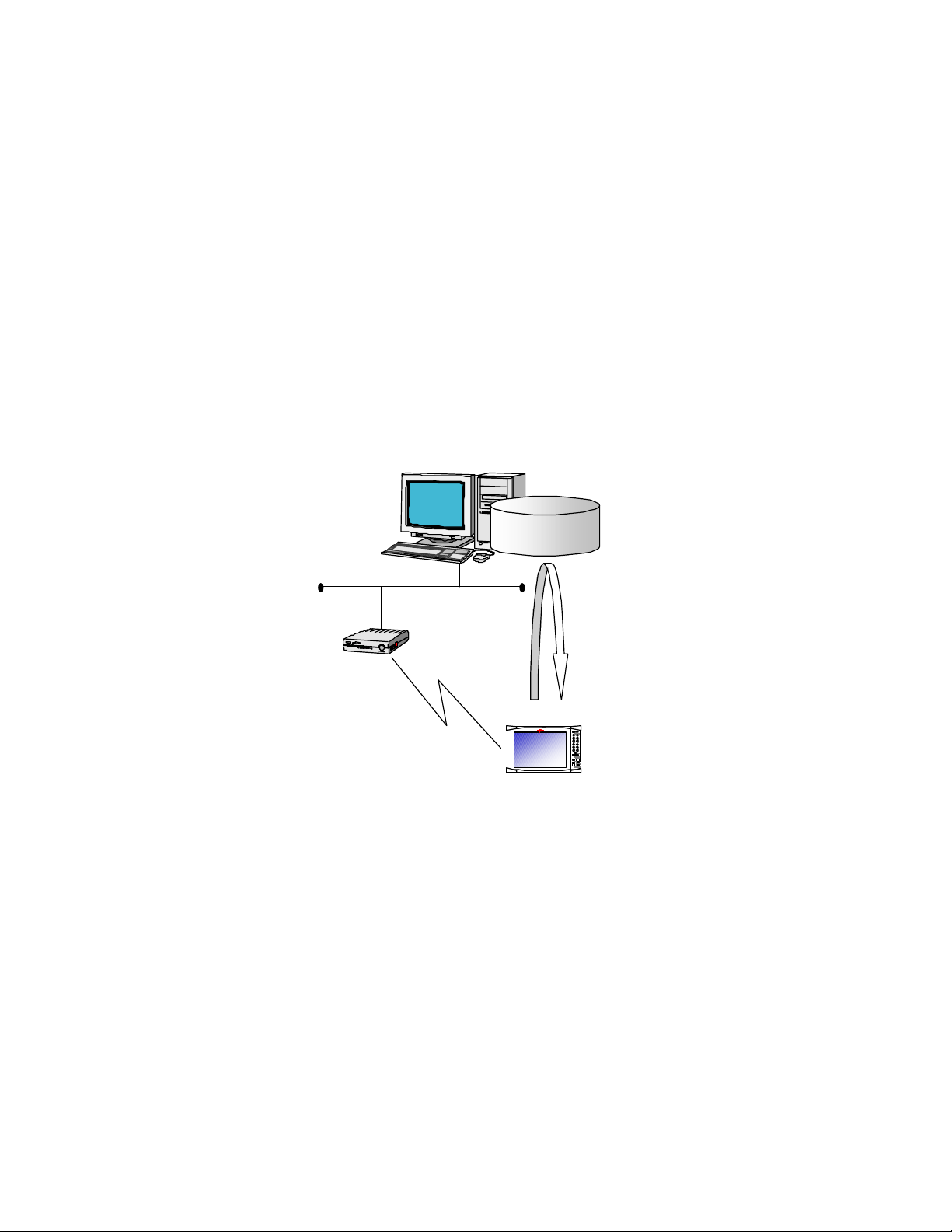
The TeamPad 7500 series is connected to a server (OS: Microsoft® Windows 2000® Server or
Microsoft® Windows NT® Server 4.0 Terminal Server Edition) through a Spread Spectrum (SS)
radio LAN and is operated after securing the connection.
This unit uses the application software on the server through an SS radio.
The settings of the LAN and the SS radio are required for this unit to be connected to the server
when setting up this unit.
(OS: Microsoft® Windows 2000® Server or Microsoft® Windows NT® Server 4.0
Terminal Server Edition)
LAN
Spread Spectrum radio LAN base station
Spread Spectrum radio
Application
Server
TeamPad 7500 / 7510
Software
1
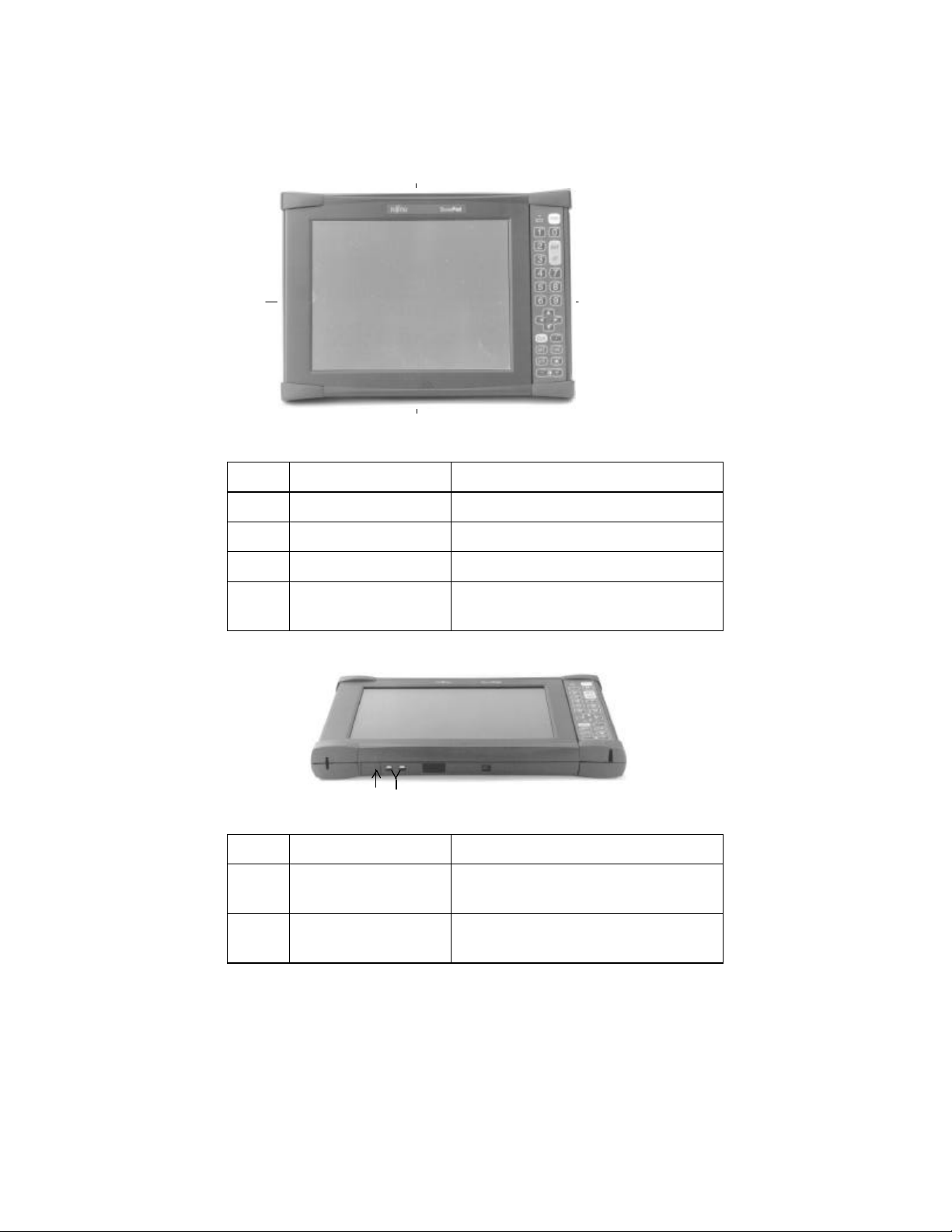
1.2 Component Names
[Front]
1
2
3
No. Component name Remarks
1 Radio antenna Built-in
2 Battery case The case that holds the battery.
3 Speaker Built-in
4 LCD touch panel Hereafter called “touch panel” or
“screen”.
4
[Bottom]
1 2
No. Component name Remarks
1 AC adapter
connector
2 Charging terminal Terminal connected to the charging
Connector for the AC adapter
adapter
2
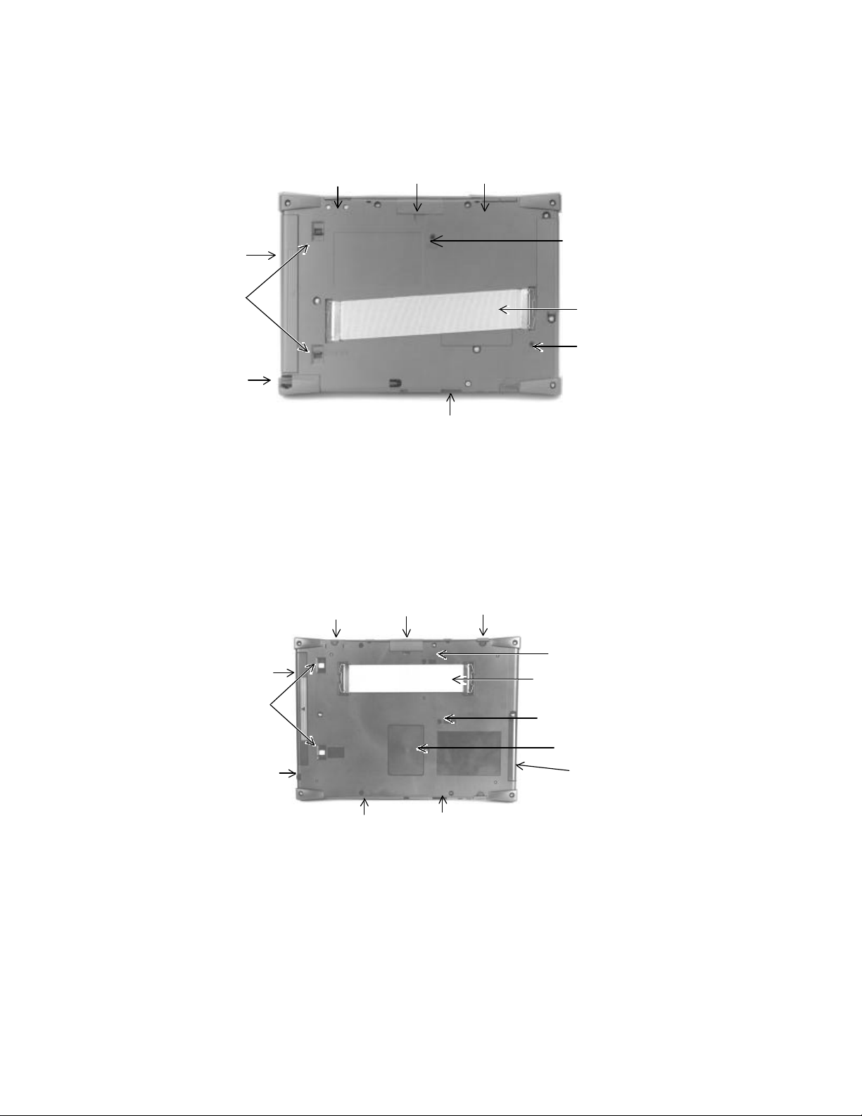
[Back]
22
88
99
667733
1111
1313
PBT7500-16
1 2 4
10
9
8
[Back]
PBT7510-16 & PBT7510-18
13
5
6
7
11
44
1010
55
3

No. Component name Remarks TP7500 TP7510
1 Bar code reader
interface
2 Extended interface Will be supported.
3 Extended interface 2 Will be supported.
4 Audio interface Will be supported.
5 Hand strap Attached to product
6 Reset switch Switch for restarting this unit
7 IrDA interface Will be supported.
8 Pen Touch panel pen
9 Battery lock switch Switch for locking the battery
10 Battery
11 ROM cover/Sub
battery
12 PC card slot Slot for PCMCIA SS RF card
13 RAS switch For Maintenance purposes only
Will be supported.
Built-in system ROM and sub battery
ü ü
ü ü
ü
ü ü
ü ü
ü ü
ü ü
ü ü
ü ü
ü ü
ü ü
ü ü
ü ü
• The RAS switch should not be pushed, because the
7500 may change out of normal operation mode.
Prohibited
4
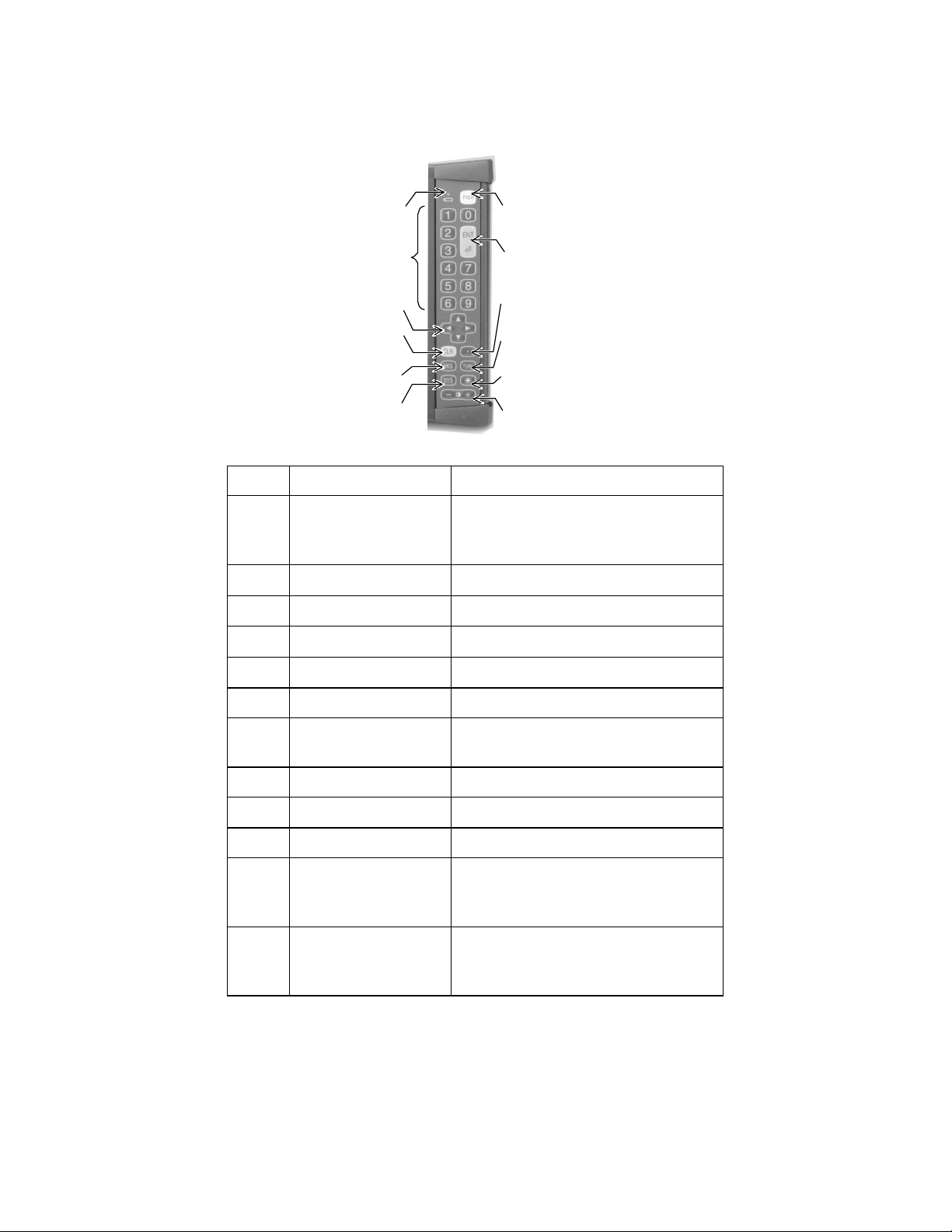
[Keys]
1
7
2
8
3
4
5
6
9
10
11
12
No. Component name Remarks
1 Power/Charging
status LED
LED for displaying the power supply
and charging status. Hereafter called
“LED”.
2 Ten key
3 Cursor key
4 Clear key
5 Backspace key
6 System key Hereafter called the [SYS] key.
7 Power key For turning on/off the power supply.
Hereafter called the [PWR] key.
8 Enter key Hereafter called the [ENT] key.
9 Decimal Point key
10 Function key Hereafter called the [FUNC] key.
11 Back light key For controlling the brightness of the
back light on the screen. Hereafter
called the [R] key.
12 Contrast key For controlling the contrast of the
screen. Hereafter called the [+] key
or the [-] key.
The keyboard layout was designed with the intention that this unit can be held in a variety of
comfortable ways and with the keyboard operating with the thumb of the user's right hand. The
following figures demonstrate comfortable ways of holding and operating the 7500.
5

6

1.3 Battery Usage
1.3.1 Battery details
• Battery type
The TeamPad 7500 Series thin client device has a 1750 mAh lithium ion battery.
A battery has multiple terminals.
• Battery Life
Charging and discharging a battery can be repeated approximately 500 times.
The duration of battery life becomes shortened as it is used repeatedly. The battery should be
replaced with a new one when the output the battery yields after a full charge becomes low.
The battery’s life depends on usage conditions such as ambient temperature and storage
conditions.
• Charging Status LED
The battery voltage may be below the specified voltage (6.6 V) when the LED flashes red at an
interval of approximately 3 seconds. In this case, the battery should be charged, or replaced
with a spare one.
However, the LED does not flash red even if the battery voltage is below the specified voltage
(6.6 V) when the AC adapter is connected.
• Charging Request Message
It can be set whether or not the message to request charging period is displayed.
>>Reference>> “2.2 Setting to connect the Server”
• Battery status
The battery status, residual battery capacity, residual expected available time, and
charging/discharging count can be confirmed.
>>Reference>> “3.3 Confirming the Battery Status”
• Trouble information LED
A battery with a low amount of charge left is indicated when the LED flashes green at an
interval of about 0.5 seconds. Replace the battery with a fully charged one.
When the LED flashes red for 5 seconds at an interval of 0.5 seconds between series, this
indicates a possible hardware fault with the 7500. Contact a Field Support Service
Representative immediately.
7

1.3.2 Battery charging
The battery should be charged when a new battery is used, or when the residual battery capacity is
low.
The battery can be charged by using any of the following three methods:
• Charging with the Charge Stand (PBT7531-01)
• Direct charging the handheld with AC adapter (PBT7631-11)
• Charging with the Battery Pack Charger (PBT7531-03)
• The plug of the AC adapter or battery pack charger
should not be pulled out of the plug socket until
charging has been completed.
• The special charging adapter, AC adapter, and battery
pack charger must be used, otherwise this unit may be
damaged due to the difference in voltage or current
capacity.
NOTE
• This unit must be turned off before charging when the
charging adapter or AC adapter is used.
• The optimum room temperature is 10oC to 30oC for
charging activities.
8

Charge with the Charger Stand
There are two methods of charging a TeamPad 7500 series thin client device with a charger stand.
The first is to charge one handheld with one charger stand, and the other is to charge two units
simultaneously with two charger stands. To charge a TeamPad 7500 series thin client device with a
charger stand, follow the steps below. Approximately 2.5 hours of charge time is required to fully
charge the handheld using a charger stand.
Charging one unit with one charger stand
This picture shows a TeamPad 7500 series sitting correctly in its charger stand. The charger
stand and AC adapter (PBT7531-02) are required for using this method.
(1) Turn this unit off.
(2) Connect the AC adapter to the AC adapter connection interface of the charging adapter.
(3) Verify the voltage levels correspond between the AC Adapter and your AC outlet. Insert the
plug of the AC adapter into the AC outlet.
9

(4) Set this unit with the battery upright on the charging adapter.
Ø Charging will automatically begin.
The LED turns green while the unit is being charged. The LED turns off when charging
has completed. Charging time is approximately 2.5 hours.
NOTE
• This unit must not be subjected to shock when setting this unit upright in the charging
stand. Problems may occur with the unit or to the charging stand if the unit is
subjected to shock.
• When the LED flashes green at an interval of approximately 0.5 seconds, it indicates
that charging is not happening correctly. In this case, the battery voltage may be below
the specified voltage, or even the charged voltage may not reach the specified value,
or the battery may simply be damaged.
The battery should be replaced with a new one. The LED turns off when the plug of
the AC adapter is pulled out of AC inlet.
• Charging cannot be performed when the LED flashes red, because the AC adapter
voltage is below the specified voltage
The AC adapter may have a problem, therefore contact a field support service
representative. The LED turns off when the plug of the AC adapter is pulled out of
the AC inlet.
Charging with two charge stands
The following steps describe charging two handheld devices with two charger stands. An AC
adapter and charging stand connector cable are required for using this method. PBT7531-11
contains a charge stand and the daisy chain cable. The picture below shows a single 7500 sitting
correctly in a charging stand which has been linked together with a second charger stand via the
charger stand connector cable.
Charger Stand
Connector cable
(1) Turn the 7500 off.
10

(2) Connect the plug sockets of the AC adapter connection interfaces of two charger stands to each
other with the charger stand connector cable.
NOTE: The charger stand has two AC adapter sockets, either socket may be used to connect
using the charger stand connector cable.
(3) Connect the AC adapter to a non-utilized plug connector in any of the two charger stands.
(4) Verify the voltage levels match between the AC adapter and the power outlet. Insert the plug of
the AC adapter into AC power outlet.
(5) Set this unit upright with the battery held in the charging adapter.
Ø Charging will automatically begin.
The LED turns green while the unit is being charged. The LED turns off when charging
has completed. Charging time is approximately 2.5 hours.
11

NOTE
• This unit must not be subjected to shock when setting this unit upright in the charging
stand. Problems may occur with the unit or to the charging stand if the unit is
subjected to shock.
• When the LED flashes green at an interval of approximately 0.5 seconds, it indicates
that charging is not happening correctly. In this case, the battery voltage may be below
the specified voltage, or even the charged voltage may not reach the specified value,
or the battery may simply be damaged.
The battery should be replaced with a new one. The LED turns off when the plug of
the AC adapter is pulled out of AC inlet.
• Charging cannot be performed when the LED flashes red, because the AC adapter
voltage is below the specified voltage
The AC adapter may have a problem, therefore contact a field support service
representative. The LED turns off when the plug of the AC adapter is pulled out of
the AC inlet.
Charge with the AC adapter
The method described below is to connect the AC adapter to the 7500 and charge the unit, while
the battery remains in the unit. The AC adapter is required for using this method. The picture below
illustrates this.
AC Adapter PBT7631-11
(1) Turn the handheld off.
(2) Connect the AC adapter to the 7500 using the ac adapter port.
(3) Verify the voltage levels of the AC adapter match the AC outlet. Insert the plug of the AC
adapter into the AC outlet.
Ø Charging will automatically begin.
12

The LED turns green while the unit is being charged. The LED turns off when charging
has completed. Charging time is approximately 2.5 hours.
NOTE
• When the LED flashes green at an interval of approximately 0.5 seconds, it indicates
that charging is not happening correctly. In this case, the battery voltage may be below
the specified voltage, or even the charged voltage may not reach the specified value,
or the battery may simply be damaged.
The battery should be replaced with a new one. The LED turns off when the plug of
the AC adapter is pulled out of AC inlet.
• Charging cannot be performed when the LED flashes red, because the AC adapter
voltage is below the specified voltage
The AC adapter may have a problem, therefore contact a field support service
representative. The LED turns off when the plug of the AC adapter is pulled out of
the AC inlet.
Charge with the dual battery pack charger
The steps below describe charging the 7500 main battery with the dual battery pack charger
(PBT7531-03). The picture below shows the dual battery pack charger with one 7500 main unit
battery in correct charging position.
(1) Connect the AC cable, which accompanies the dual battery pack charger, to the pack charger.
(2) Verify the voltage levels of the AC cable correspond with the AC outlet. Insert the AC cable in
the AC outlet.
(3) Connect the battery to the battery pack charger. Up to two batteries can be connected
simultaneously.
Ø Charging will automatically begin.
The LED turns green while the unit is being charged. The LED turns off when charging
has completed. Charging time is approximately 2.5 hours.
13

NOTE
If the LED of the dual battery pack charger flashes red, verify that the battery(s) is
connected securely inside the pack charger. If the battery(s) is connected correctly and the
LED is still flashing red, than that indicates a problem with the battery or the battery has
reached the end of its life cycle. Replace the battery(s) with a new one.
14

1.3.3 Setting/Removing the battery
Setting the battery
(1) Two battery lock switches reside on the back surface of the 7500 series device.
Slide the battery lock switches to the [UNLOCK] position.
(2) Insert the battery correctly into the handheld until a “click” is heard.
(3) Slide the battery lock switches to the [LOCK] position.
(4) Reverse these steps to insert a new or fully charged battery into the handheld.
NOTE
The power supply will turn on when the battery lock switches are set to the [LOCK]
position.
Upper battery lock switch
Downward to
UNLOCK
Insert the battery
LOCK
Lower battery lock switch
15

2 TeamPad 7500 Series Setup
This battery might be damaged if the LED flashes green for 5 seconds at an interval of
Correct setup of the TeamPad 7500 series device consists of the following tasks:
Network Settings
Change network settings and Spread Spectrum radio settings.
Server Settings
Set connect entry to server.
Terminal Server/Power Saving Settings
Set power saving and auto-connect to server settings.
NOTE
Before setup can begin, please charge the battery and insert it into the handheld. For more
information, please refer to:
1.3 Battery Usage
>>Reference>> “3.7 Adjusting the TeamPad 7500 Setup Settings” when it is set up again.
2.1 Setting the Network
(1) Turn this unit on by pressing the PWR key until LED flashes bright green (about 1 second).
Ø This unit will boot up, and the [Change Settings] window for network settings will be
displayed.
NOTE
16

about 0.5 seconds. Replace with a new battery.
There might be a hardware fault if the LED flashes red for 5 seconds at an interval of
about 0.5 seconds. Contact a field support service representative.
(2) Tap on the [Yes] button on the [Change Settings] window for network settings.
Ø The screen keyboard and control panel are displayed.
>>Reference>> “3.8 Using the Screen Keyboard” for more information on the screen
keyboard.
& Advice &
Tap on the [No] button to set the terminal server/power saving without changing the
network settings when this unit is set up again. By tapping on the [No] button, the screen
keyboard and the [Power savings and connecting to Terminal Server] window is
displayed.
>>Reference>> “2.2 Setting to connect the Server” about the [Change setting] window
for network settings.
(3) Double-tap on the [Network] icon on the control panel.
Ø The [Network] window is displayed.
(4) Set the items on the [Network] window according to the explanation displayed on the
[Network] window.
Tap on the [OK] button after the setting has been terminated.
Ø The [Network] window is closed.
NOTE
Ignore the following message displayed, and tap on the [OK] button:
“The new setting becomes valid when the adapter is used the next time. The new setting
becomes valid by reinserting the adapter into the device after taking it out of the device if
the adapter has been Inserted into the device.”
NOTE
If using a Symbol Spectrum24 card, refer the following action.
If using another vender’s RF card, please refer to that specific setup instruction for
that vender's RF card.
(5) Double-tap on the [Spectrum24 Settings] icon on the control panel to change the SS radio
setting.
Ø The [Spectrum24 Settings] window is displayed.
(6) Set the items on the [Spectrum24 Settings] window.
Tap on the [OK] button after the setting has been terminated.
17

NOTE
Contact a network system administrator to confirm the settings of items on the
[Spectrum24 Settings] window.
Ø The [Spectrum24 Settings] window is closed.
(7) Tap on [Close] from the [File] menu on the control panel.
Ø After the control panel is closed, the [Power savings and connecting to Terminal Server]
window is displayed.
18

2.2 Setting to connect the Server
>>Reference>> “3.8 Using the Screen Keyboard” for more information on about the screen
keyboard.
(1) Tap on the [Yes] tab on the [Change settings] window.
Ø The [WTS Connection Wizard] window is displayed.
& Advice &
Tap on the [No] tab, don’t change WTS connection settings to change settings of this unit.
Tap on the [No] tab, display the [Setting the Terminal Server/Power Saving] window.
>>Reference>> “2.3 Enter the Settings for the Terminal Server/Power Saving” to display
the “Setting the Terminal Server/Power Saving” window.
(2) Set the following settings with the 1st “WTS Connection Wizard” windows.
19

[Name] entry field
Input “fht”. (Fixed)
[Server] entry field
Input the server’s IP address.
[Low Speed Connection] check box
Don’t use “Low Speed Connection”.
Don’t check this check box.
& Advice &
Following items is the tab which mean the “WTS connection wizard” window.
[Back] bottom
Back 1 window to display the “WTS connection wizard” window.
[Next] bottom
Forward 1window to display the “WTS connection wizard” window.
[Cancel] bottom
Cancel all settings with the “WTS connection wizard” windows, and display the
“Setting the Terminal Server/Power Saving” window.
>>Reference>> “2.3 Enter the Settings for the Terminal Server/Power Saving” to display
the “Setting the Terminal Server/Power Saving” window.
(3) Tap on the [Next] tab.
Ø Display the 2nd [WTS Connection Wizard] window.
20

Ø
(4) Set the following settings on the 2nd [WTS Connection Wizard] window.
• [Automatic Connection To Server] check box
This check box sets whether or not this unit is automatically connected to the server when this
unit is turned on.
NOTE
Don’t uncheck this checked box, the user name, password, and the domain name must be
entered by pressing the Ten key when this unit is connected to the server.
>>Reference>> “3.1.1 Turning on the power supply ”
Usually, you can check off [Automatic Connection To Server] this check box.
• [Username] entry field
Enter this field when [Automatic Connection To Server] check box.
Enter the username to connect the server automatically.
[Password] entry field
Enter this field when [Automatic Connection To Server] check box.
Enter the password to connect the server automatically.
Enter the same password to entry the server in [Password] entry field.
When the [Password] entry field over flow at the server, an error has occurred at the end of
[WTS Connection Wizard]. At this time, enter the correct [Password] entry field.
[Domain] entry field
Enter this field when [Automatic Connection To Server] check box.
Enter the domain to connect the server automatically.
(5) Tap on the [Next] tab.
Ø Display the 3rd [WTS Connection Wizard] window.
21

(6) Set the following settings on the 3rd [WTS Connection Wizard] window.
[Desktop]
Select [Desktop] when an application software is not started just after connecting to the
server.
[Application File Name]
Select [Application File Name] when an optional application software is started just after
connecting to the server. Enter the file name of the application software to be started to the
lower entry field, starting with the drive name.
[Work Directory] entry field
The [Work Directory] entry field becomes valid when [Application File Name] is selected in
[Program Started When Connecting To Server].
(7) Tap on the [Next] tab.
Ø Display the 4th [WTS Connection Wizard] window and display the connection entry to set
this time. Don’t tap on the [Next] tab at the 3
rd
[WTS Connection Wizard] window, make
sure to set the [Application File Name] and [Work Directory].
(8) Tap on the [Finish] tab on the 4th [WTS Connection Wizard] window.
22

Ø Close the [WTS connection wizard] window, and display the [Setting the Terminal
Server/Power Saving] window.
Ö This is the end of operation to set connection the server.
Refer back to “2.3 Enter the Settings for the Terminal Server/Power Saving” for more
information on this process.
2.3 Enter the Settings for the Terminal Server/Power Saving
>>Reference>> “3.8 Using the Screen Keyboard” for more information about the screen
keyboard
(1) Tap on the [Power saving] tab on the [Power savings and connecting to Terminal Server]
window.
(2) Set the following with the [Power savings] tab:
• [Default brightness of back light]
Select the brightness of the back light when the power supply of this unit is turned on, from the
list box.
• [Auto back light off timer]
Select the time between the no-operation time and the automatic set to the darkest setting of
this unit from the list box. Select [Inhibit] if the back light is not set to the darkest setting
automatically.
• [Auto power off timer]
Select the time between the no-operation time and the automatic power-off of this unit from the
list box. Select [Inhibit] if the power supply of this unit is set to not automatically turn off.
• [Battery low message]
Click off the check box to display the message when the residual battery capacity has reached a
low amount.
23

(3) Tap on the [Server connection] tab.
(4) Set the following with the [Server connection] tab:
• [Auto Connect to a server]
Click off the [Enable] check box to connect server automatically when terminal is turned on.
& Advice &
If [Enable] check box is not checked off, the [Terminal Server client] window will be
displayed when terminal is turned on. It can control server connection with using
[Terminal Server Client] windows. The server name on [Terminal Server client] windows
will be set with the value is configured on [Server] entry field of [WTS wizard] as default.
>>Reference>> Please refer to “3.1.1 Turning on the Power Supply” about [Terminal
Server Client]
Please check this check box normally.
(5) Tap on the [OK] button on the [Power savings and connecting to Terminal Server] window.
Ø The [Save Settings] window is displayed.
24

This unit will automatically attempt to connect to the server by turning on the power
& Advice &
The [Initialize] tab is used for initializing the setup settings.
>>Reference>> “3.7.2 Initializing the setup settings”
(6) Tap on the [Yes] button on the [Save Settings] window.
Tap on the [No] button to terminate the setup without saving any information that has been set
during the setup.
Ø The information set during the setup is not saved, and the power supply of this unit is
automatically turned off if the [Yes] button has been tapped.
NOTE
It takes a few seconds for the power supply of this unit to be automatically turned off.
The [PWR] key must not be pressed before the unit powers off automatically.
3 Using The TeamPad 7500 Series Units
3.1 Turning on/off the Power Supply
3.1.1 Turning on the power supply
(1) Press the PWR key while the power supply is being turned off.
Ø The power supply is turned on.
The LED is lit in green while the screen is not displayed.
NOTE
• There might be a possible hardware fault if the LED flashes red for 5 seconds at an
interval of about 0.5 seconds. Contact a field support service representative.
• The [Change setting] window for network settings is displayed by pressing the [PWR]
key when this unit has not set up, or when the setup settings have been initialized.
Press the [PWR] key again after performing the setup.
>>Reference>> “2 TeamPad 7500 Setup” about the setup.
& Advice &
25

supply of this unit when the automatic connection to the server is set during the setup.
Enter the IP address of the server in the [Terminal Server Client] window. To display this
window press the Ten key when turning on this unit if the automatic connection to the
server has not been set during the initial setup.
>>Reference>> “2.3 Enter the Settings for the Terminal Server/Power Saving” about the
automatic connection to the server.
26

3.1.2 Turning off the power supply
(1) Execute any of the following operations:
• Terminate any application software currently running.
• Press and hold the [PWR] key (for about 3 seconds) until the power supply has turned off,
if the application software is not starting.
Ø The power supply is turned off.
Perform the operation (2) continuously if the power supply is not turned off after
terminating the application software.
(2) Execute any of the following operations if the power supply is not turned off even by executing
the operation (1):
• Tap on the [Power Off] button if the [Reconnect to the Terminal Server] window is
displayed.
• Press and hold the [PWR] key (for about 3 seconds) until the power supply is turned off if
the [Reconnect to the Terminal Server] window is not displayed.
Ø The power supply is turned off.
27

3.2 Controlling the Speaker’s Volume
The following describes the operation to control the speaker’s volume.
NOTE
The volume is automatically set to [High] when this unit has been restarted using the Reset
switch, or when the battery has been replaced with a new one. Adjust the speaker’s
volume if necessary.
(1) Press the [R] key by holding on the [SYS] key while the power supply is being turned on.
Ø The [Volume and Battery] window will be displayed.
>>Reference>> “3.3 Confirming the Battery Status” for battery information.
(2) Select the speaker’s volume from [Volume].
(3) Tap on the [OK] button.
28

3.3 Confirming the Battery Status
The following describes the operation to confirm the battery status, residual battery capacity,
residual expected available time, and charging/discharging count.
(1) Press the [R] key by holding on the [SYS] key while the power supply is being turned on.
Ø The [Volume and Battery] window is displayed.
>>Reference>> “3.2 Controlling the Speaker’s Volume” for adjusting the speaker’s volume.
(2) Confirm the battery status by using [Battery].
The items in [Battery] have the following meanings:
• Status
The battery status is displayed as [Normal], [Insufficient Residual Capacity], [Abnormal],
or [Undetermined].
NOTE
• The battery capacity is insufficient if [Insufficient Residual Capacity] is displayed.
Charge the battery, or replace it with a spare battery.
• The battery is abnormal if [Abnormal] is displayed. Replace it with a spare battery.
• Please press the [R] key by holding on the [SYS] key again. The battery or this unit
is abnormal if [Undetermined] is displayed after few times pressing the [R] key by
holding on the [SYS]. Please contact field support service.
29

• Residual battery capacity
The residual battery capacity is displayed with %.
However, [Undetermined] will be displayed in [Residual Battery Capacity] if
[Undetermined] is displayed in [Status].
• Residual expected available time
The residual expected available time for the battery is displayed in the unit of minutes.
However, [Undetermined] will be displayed in [Residual Expected Available Time] if
[Undetermined] is displayed in [Status].
• Charging/discharging count
The charging/discharging count where the battery was repeated in the past is displayed.
However, [Undetermined] will be displayed in [Number of Charging/Discharging periods] if
[Undetermined] is displayed in [Status].
(3) Tap on the [OK] button.
30

3.4 Controlling the LCD Panel Back Light
The following describes the operation to control the LCD panel back light.
>>Reference>> “2.2 Setting to connect the Server” about setting the back light brightness when
turning on the power supply.
(1) Press the [R] key while the power supply is being turned on.
Ø Each time the [R] key is pressed, the brightness of the back light is changed as follows:
Dark Slightly dark Slightly bright Bright
3.5 Controlling the Contrast of the LCD Panel
The following describes the operation to control the contrast of the LCD panel.
(1) Press the [+] key or [-] key while the power supply is being turned on.
Ø The darkness of the screen is increased each time the [+] key is pressed.
The brightness of the screen is increased each time the [-] key is pressed.
31

3.6 Calibration of the LCD Touch Panel
The tapped [+] does not disappear if the tapped position is about 1 cm distant from the
The LCD touch panel has lost calibration accuracy if the touch panel does not respond when
tapping on the screen, or if a different portion of the touch screen is activated other than the part
which received the input.
In this case, the operation to correct the inaccuracy of the touch panel should be executed. This
operation is called “Touch Panel Calibration”. There is no need to perform this calibration when
this unit is purchased, because the touch panel has been calibrated.
NOTE
• The [PWR] key must not be pressed while the touch panel calibration tool is running.
The touch panel calibration would then need be re-executed because the setting of
touch panel calibration becomes invalid if the [PWR] key is pressed.
• The touch panel calibration must be executed using a fully-charged battery or using
the AC adapter connected to the unit. The setup settings are initialized if the battery
capacity has become insufficient during the touch panel calibration.
• If battery charge become low during the touch panel calibration, replace the battery,
then re-execute the touch panel calibration.
(1) Press the [PWR] key by holding on the [SYS] key while the power supply of this unit is being
turned off.
Ø The touch panel calibration screen is displayed.
(2) Tap on the [+] mark displayed on the touch panel calibration screen with a stylus.
Tap on the [Cancel] button to stop the touch panel calibration.
NOTE
32

center of [+]. In this case, tap on the [+] mark again.
& Advice &
The touch panel calibration can be stopped by pressing the [ENT] key if the [Cancel]
button is not valid.
Ø The tapped [+] disappears, and another [+] is displayed at a different position.
However, the touch panel calibration will stop, and the unit will restart if the [Cancel]
button is tapped.
(3) Tap on [+] with a pen. Five [+] symbols are sequentially displayed. Tap on these five symbols
with a pen in the order indicated on the display.
Ø The touch panel calibration completion window is displayed by tapping on the fifth [+]
symbol.
(4) Tap on the [OK] button on the message window.
& Advice &
The touch panel calibration can be terminated by pressing the [ENT] key if the [OK]
button is invalid.
Ø
This unit is restarted.
% Request %
• The setup settings are initialized if the battery becomes insufficient from when the
[OK] button is tapped until this unit is restarted. Perform the setup functions again.
33

• It takes a few seconds for this unit to be restarted after tapping on the [OK] button.
The [PWR] key must not be pressed before this unit is restarted.
34

3.7 Adjusting the TeamPad 7500 Setup Settings
3.7.1 Changing the setup settings
The following describes the operation to change the setup settings.
(1) Press the [PWR] key while holding down the [FUNC] key, [SYS] key, and an optional location
on the touch panel when the power supply of the unit is being turned off.
Ø This unit is started, and the [Change setting] window for network settings is displayed.
(2) Change the setup settings according to your needs.
>>Reference>> From the operation (2) in “2.1 Setting the Network” to “2.3 Enter the
Settings for the Terminal Server/Power Saving” about the setup settings.
3.7.2 Initializing the setup settings
The following describes the operation to initialize the setup settings to the mode when this unit is
purchased.
& Advice &
• The [Change setting] window for network settings is displayed by turning on this unit
after initializing the setup settings. Set the network.
• The touch panel calibration mode is not initialized even if the setup settings are
initialized.
(1) Press the [PWR] key while holding on the [FUNC] key, [SYS] key, and an optional location on
the touch panel when the power supply of this unit is being turned off.
Ø This unit is started, and the [Change setting] window for network settings is displayed.
(2) Tap on the [No] button on the [Change setting] window for network settings.
Ø The screen keyboard and [Power savings and connecting to Terminal Server] window is
displayed.
(3) Click on the [Initialize] tab on the [Power savings and connecting to Terminal Server] window.
(4) Click off the [Initialize] check box in the [Initialize] tab.
35

(5) Tap on the [OK] button on the [Power savings and connecting to Terminal Server] window.
Ø The [Save Settings] window is displayed.
(6) Tap on the [Yes] button on the [Save Settings] window.
However, if the setup settings are not initialized, then tap on the [No] button.
Ø The setup settings are initialized, and the power supply of this unit is automatically turned
off if the [Yes] button has been tapped.
The setup settings are not initialized, and the power supply of this unit is automatically
turned off if the [No] button has been tapped.
36

3.8 Using the Screen Keyboard
The screen keyboard is a full alphanumeric keyboard which can be accessed by pressing the [SYS]
and [DOWN ARROW].
3.8.1 Entering the characters
(1) Tap on a key on the screen keyboard.
Ø The character is entered.
3.8.2 Changing the mode
The screen keyboard has two modes, i.e., alphabetical lowercase character mode and alphabetical
uppercase character mode. The screen keyboard is displayed in alphabetical lowercase character
mode.
(1) Tap on the [CAP] key on the screen keyboard while the screen keyboard is being displayed.
Ø The alphabetical lowercase character mode and alphabetical uppercase character mode are
switched alternately each time the [CAP] key is tapped.
4 LED Display
The following explains the action to be taken when the LED is lit or flashes.
4.1 LED Displayed While in Operation
Take action according to the following “Response” if the LED blinks during operation:
LED display Response
Color Display status
Red Flash (at an interval of
about 3 seconds)
The battery voltage is below the specified
voltage.
Charge the battery, or replace the battery with
a spare battery.
However, the LED does not blink when this
unit is connected to the AC adapter, even if
the battery voltage is below the specified
voltage.
4.2 LED Displayed When the Power Supply Is On
Take action according to the following “Response” if the LED is lit or flashes when the power
supply is turned on:
37

LED display Response
Color Display status
Green Fully Lit This unit has initiated the boot up process.
The LED is lit when the [PWR] key is
pressed until the screen is displayed.
Red Blink (for 5 seconds at
an interval of about 0.5
This unit is abnormal. Contact a Field
support service representative.
seconds)
4.3 LED Displayed While Charging Is Performed
4.3.1 LED of this unit during charging
Take action according to the following “Response” if the LED of this unit is lit or flashes while
charging is being performed:
LED display Response
Color Display status
Green Lit Charging is being performed. The LED
switches off after charging is completed
Green Flash
(at an interval of about
0.5 seconds)
Charging is not performing normally. The
battery voltage is below the normal voltage
range, or the battery voltage has not reached
the specified voltage even after charging has
completed.
Replace the battery with a new one. The
LED switches off by pulling the plug of the
AC adapter out of the plug socket.
Red Lit The AC adapter voltage is below the specified
voltage , so charging cannot be performed.
The AC adapter may have a problem,
therefore contact a field support service. The
LED switches off by pulling the plug of the
AC adapter out of the plug socket.
4.3.2 LED of the dual battery pack charger during charging
Take action according to the following “Response” if the LED of the dual battery pack charger is lit
or flashes while charging is being performed:
LED display Response
Color Display status
Orange Lit During charging.
38

Green Lit Charging is completed.
Red Blink Charging cannot be performed since the
battery may not be connected correctly to the
battery pack charger or the battery may be
damaged.
Correctly connect the battery to the battery
pack charger, or replace the battery with a
new one.
39

5 Spread Spectrum Radio
The TeamPad 7500 series of thin client devices are designed for use with PCMCIA RF radio cards
and radio LAN based access points for communication with a terminal server. The TeamPad 7500
series devices are “RF friendly” devices and have been tested with PCMCIA radio cards and RF
backbone equipment from the major RF equipment vendors. Please refer to your Fujitsu-ICL
Systems, Inc. technical representative for information regarding specific TeamPad 7500 series
models and FCC certification of specific RF solutions.
The radio system of this unit adopts the spectrum diffusion system by using the spread spectrum
2.4 GHz band. The user can use this unit without obtaining the radio communication license.
The communicable range is within a 7 m to 35 m radius from the base station as a center under the
environment of a shop.
(The communicable range depends greatly on the environment. The communicable range is up to
70 m or so for the open space.)
CAUTION
• This unit must not be used near machinery which may
cause electric noises such as microwave oven and
security gate.
• This unit should be used distant from TV, radio, and
other radio sets.
40

6 KeyGen
Keygen is a utility program that allows the input of data from a PSC 6000 QuickScan scanner
attached to a TeamPad 7500 series bar code port. The program attaches it self to the BCR port,
intercepts data from the scanner and passes it to the operating system as though the data came in as
keyboard data. The data is passed to the currently open application.
Installation:
1. Copy the keygen.exe to the appropriate directory (C:\Fujitsu) on your Terminal Server.
2. On your TeamPad 7500 series device, create a shortcut that points to keygen.exe
3. Drag that shortcut into the startup folder if you want keygen to start automatically. Otherwise
just leave it on your desktop and start it manually.
7 RT Mouse
RTMouse is a utility program that converts a tap on the LCD panel (mouse click) on a TeamPad
7500 series device from a “left mouse click” (default) to a “right mouse click”. The program
facilitates the right mouse click functions required by the Windows operating environment, such as
when defining a new desktop icon (shortcut).
Installation:
1. Copy the rtmouse.exe to the appropriate directory (C:\Fujitsu) on your Terminal Server.
2. On your TeamPad 7500 series device, create a shortcut that points to keygen.exe
3. Drag that shortcut into the startup folder if you want keygen to start automatically. Otherwise
just leave it on your desktop and start it manually.
41

8 If A Message Is Displayed...
The radio LAN driver has not been
The radio LAN driver has not been installed or has
Take action according to the “Response” if any of the following messages are displayed.
Message Response
The DHCP could not obtain the IP
address. Reinsert the card, or allocate
the address manually.
An error has occurred, therefore stop
the touch panel calibration.
The server could not be connected. The connection to the server has failed. Verify the
Charge the battery. The residual battery capacity has become insufficient.
The DHCP could not obtain the IP address. Verify
whether or not the network has been set for the
DHCP to obtain the IP address.
Contact the network administrator if the problem
persists.
An error has occurred during the touch panel
calibration.
Tap on the [OK] button to stop the touch panel
calibration, then re-execute the touch panel
calibration.
>>Reference>> “3.6 Calibration of the Touch
Panel”
if an error occurs frequently, contact a Field support
service representative.
setup settings.
>>Reference>> “3.7 Adjusting the TeamPad 7500
Setup Settings”
Charge the battery, or replace the battery with a new
one.
>>Reference>> “1.3 Battery Usage”
An error has been detected in the
flash ROM.
No data can be saved in the flash
ROM.
The flash ROM clearing has failed. The flash ROM cannot be cleared. Contact a Field
Message
The set data stored in the flash ROM has been
damaged. Set up this unit again.
>>Reference>> “3.7 Adjusting the TeamPad 7500
Setup Settings”
Contact a Field support service representative if an
error occurs frequently.
No data can be written to the flash ROM. Contact a
Field support service.
support service.
Response
42

installed. been damaged. Contact a Field support service
representative.
Terminal Server Client Disconnected. The message may have exceeded the radio
communication range. Send the message again within
the radio communication range.
>>Reference>> “5 SS Radio”
43

9 Troubleshooting
Take action according to “Response” before contacting a Field support service representative if any
of the following symptoms has been detected during using this unit.
Symptom Response
The power supply cannot be
turned on.
The battery may have reached the end of its lifecycle.
Make sure the battery has been correctly installed. For
The screen has either been
significantly darkened or
brightened, therefore it is hard to
see.
The battery charge may be low. Replace the low capacity
The screen is displayed briefly
and disappears when the power
supply is turned on by pressing
the [PWR] key.
The battery charge may be low. Replace the low capacity
battery with a fully charged one.
>>Reference>> “1.3 Battery Usage”
Replace the insufficient battery with a new one.
>>Reference>> “1.3 Battery Usage”
example, the battery lock switch might be set to the
[UNLOCK] setting.
>>Reference>> “1.3.3 Setting/Removing the battery”
Control the contrast of the screen.
>>Reference>> “3.5 Controlling the Contrast of the
Screen”
battery with a charged one.
>>Reference>> “1.3 Battery Usage”
The battery charge may be low. Replace the battery with a
charged one.
>>Reference>> “1.3 Battery Usage”
No sound is coming from the
speaker.
The touch panel is not valid. The coordinates on the touch panel may have shifted.
Terminal Server Client
Disconnected.
The speaker’s volume may be set to [SILENCE]. Verify
the speaker’s volume.
>>Reference>> “3.2 Controlling the Speaker’s Volume”
Execute the touch panel calibration.
>>Reference>> “3.6 Calibration of the Touch Panel”
The message may have exceeded the radio communication
range. Send the message again within the radio
communication range.
>>Reference>> “5 SS Radio”
A TeamPad 7500 Specifications
44

Item Specifications
Controller CPU 64-bit RISC CPU -- 85MHz
Memory ROM: 16 MB + 2 MB (Flash ROM)
RAM: 16 MB
Display Type LCD
Screen size
800 (width) × 600 (length), SVGA, 256 colors
Display lighting High-brightness back light with the FL tube
Operation panel
Touch panel, Back Light key, Contrast key, Contrast key (× 2),
Function key, System key, Power key, Reset switch, Ten key,
Enter key, Cursor key, Clear key, Decimal Point key,
Backspace key.
Audio Speaker output (Speaker x 1 built-in)
Radio 2.4 GHz, spread spectrum, radio LAN, based on 802.11, 2
Mbps.
Power supply Battery Li ion battery pack, 1750 mAh
Operational time Approx. 3 hours
Charging period About 2.5 hours
Environmental
conditions
Temperature Operation: 32oF to 104oF (0oC to 40oC)
Storage: -4oF to 140oF (-20oC to 60oC)
Humidity Operating: 20% to 85%
Storage: 20% to 85%
Dimensions
10.0" W x 1.0" H x 7.0" D (255 × 25 × 178 mm)
Weight 1.9 lbs. 860g (including the battery’s weight)
45

B Expendable Supplies
The following describes the expendable supplies which the user needs when making replacements in
this unit.
Product name Product number Life
1750 mAh Battery
Pack
Other parts except the above may need to be replaced at the user’s cost if they are used beyond the
Fujitsu-defined limits of use.
Contact a Field support service representative for details of the Fujitsu-defined limits of use as well
as the parts that may be replaced.
PBT7531-05 About 500 charging and discharging times
(The charging and discharging count may be
less than 500, depending on the operational
conditions.)
46

C Accessories
Accessory Remarks
Battery pack 1 ea. PBT7531-05
Pen Stylus 1 ea. PBT7633-05
Hand strap 1 ea. PBT7633-01
Instruction Manual 1 ea. PBT90000079
* The pen and hand strap can be purchased individually by specifying the above Model
numbers.)
47

D Optional Equipment
Product name Model number Specification
Dual Battery Pack
Charger
Neck strap FHTNS701 Strap used for suspending this unit from the
PBT7531-03
Unit for charging one or two batteries.
The charging period is about 2.5 hours.
neck of the user
48

Index
A
B
C
Accessories.................................................................................45
Battery
charging..................................................................................7
details.....................................................................................6
removing..............................................................................14
setting..................................................................................14
status, confirming..................................................................28
usage......................................................................................6
Calibration of the touch panel.......................................................31
Changing mode...........................................................................35
Charging with AC adapter............................................................11
Charging with battery pack charger...............................................12
Charging with charging stand..........................................................8
Component names.........................................................................2
Controlling back light...................................................................30
Controlling contrast .....................................................................30
Controlling speaker's volume........................................................27
E
Entering characters......................................................................36
Expendable supplies.....................................................................44
L
LED...........................................................................................36
displayed while in operation....................................................36
displayed while power supply is on .........................................37
of battery pack charger during charging...................................38
of this unit during charging.....................................................37
M
49

Message .....................................................................................40
O
Optional equipment .....................................................................46
P
Power supply
turning off ............................................................................25
turning on.............................................................................25
S
Setting network...........................................................................18
Setting terminal server/power saving.............................................22
Setup
changing settings ...................................................................34
initializing settings..................................................................34
operation to be performed first ...............................................17
Specifications..............................................................................43
SS radio .....................................................................................39
T
TeamPad (FHT601)
before using............................................................................1
overview of ............................................................................1
using....................................................................................25
Troubleshooting..........................................................................42
U
Using screen keyboard.................................................................36
50
 Loading...