

Page 1

CHAPTER
9
Cabling and Configuring the
25 Mbps Port Adaptor Modules
This chapter describes cabling and configuration procedures for the LightStream 1010
ATM switch 12-port,25-Mbps PAMs. When yourswitch leavesthe factory, itis configured
as specified inyour order and is ready for installation and startup. As your communication
requirements change, you might want to upgrade your system, add components, or change
the initial configuration.
Software and upgrades require specific document part numbers and other frequently
updated information; therefore, only basic software configuration guidelines are included
in this publication. Detailed, up-to-date instructions are included in the LightStream 1010
ATM Switch Software Configuration Guide and command-line interface (CLI) command
descriptions are provided in the LightStream 1010 ATM Switch Command Reference.
This chapter contains the following information:
• Overview of the 25-Mbps Port Adapter Module
• Connecting the Interface Cables and Checking the LEDs
• Configuring the Interfaces
Overview of the 25-Mbps Port Adapter Module
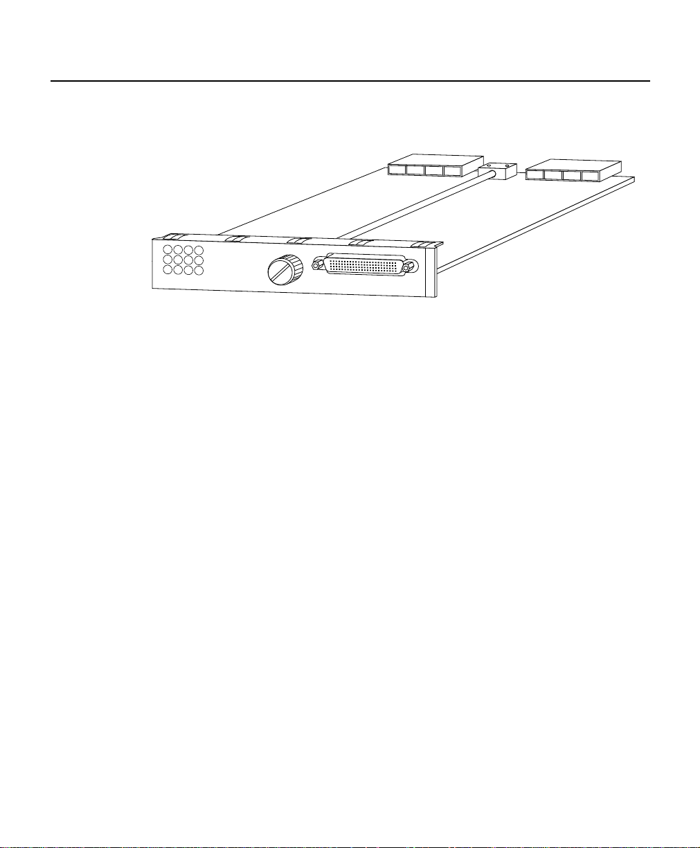
The 25-Mbps Port Adapter Module has twelve 25.6 Mbps ATM ports. Each port is
compliant with the ATM Forum PHY standard for 25.6 Mbps over twisted pair cable and
is ideal for workgroup links (see Figure 9-1). Any of the twelve ports on the PAM can be
configured as redundant links using the switch's routing protocols. The PAM has a 96-pin
Molex connector and a multi-leg 12 RJ-45 cable assembly.
Cabling and Configuring the 25 Mbps Port Adaptor Modules 9-1
Page 2
Overview of the 25-Mbps Port Adapter Module
Figure 9-1 25-Mbps PAM
8
11
5
2
7
4
10
1
9
6
3
ATM25-12 PORT
0
Each port on the PAM supports single, local clocking only.
Traffic-pacing allows the aggregate output traffic rate on port group 0 to 5 or 6 to 11 to be
set to a rate below the line rate; this is useful when communicating with a slow receiver.
Pacing cannot be done on any individual port but on a group of six ports.
The plug-and-play mechanisms of the LightStream 1010 allow the switch to come up
automatically. All configuration information for port adapter modules can be saved
between hot swaps and switch reboots, while interface types are automatically discovered
by the switch. This eliminates mandatory manual configuration.
H8799
The LightStream 1010 supports any combination of port adapter modules. Customers can
configure their switches with only the number and type of interfaces required, with up to
96 25-Mbps ports.
This section describes the following:
• 25 Mbps PAM Features
• 25 Mbps PAM Applications
9-2 LightStream 1010 ATM Switch PAM Installation Guide
Page 3

25 Mbps PAM Features
The 25 Mbps PAMs provide the following features:
• Support for 12 ATM UNI ports at standard throughput rate of 25.6 Mbps full duplex.
• Compatible with ATM Forum 25.6 Mbps PHY specification for UTP-3, UTP-5, or
STP-5 except that the RJ-45 connector is replaced with a Molex 96-pin female
connector. (A cable assembly with 12 RJ-45 standard connectors is provided with the
PAM.)
• A CPU bus interface for control and monitoring of the board ID EEPROM and LEDs.
• Priority queueing (4 levels) at each transmit (TX) output port.
• Buffermemory for transmit andreceive (RX) cells and for each group ofsixports; 128K
by 16-bit local external SRAM for flexible queueing of 4,092 cells in transmit data path.
The minimum queue allocations are selectable for each transmit queue priority from 4
to 60 cells, in multiples of 4, via software control.
• Support for multicasting to any combination of 12 transmit ports.
• Provides individual enabling for TX and RX of each port separately.
• Provides individual loopback control in each PMD device on board, via software
control.
Overview of the 25-Mbps Port Adapter Module
• Three 24-bit statistics counters per port for receive discarded cells, plus received and
transmitted cells.
• Can generate per-port and per-condition maskable interrupt to the CPU in case of
physical or line error conditions.
25 Mbps PAM Applications
The 25-Mbps port adapter module has 12 ports and is ideal for workgroup links. Figure 9-2
is an example of the 25-Mbps PAM application.
The various 25-Mbps PAMs provide 12 UTP-5 interface connections from the desktop to
the wiring closet.
Cabling and Configuring the 25 Mbps Port Adaptor Modules 9-3
Page 4

Connecting the Interface Cables and Checking the LEDs
Figure 9-2 25-Mbps PAM Applications
ATM switch
25-Mbps
connections
Distribution
block
25-Mbps
connections
NM3992
Connecting the Interface Cables and Checking the LEDs
All ATM interfaces are full duplex. You must use the appropriate ATM interface cable to
connect the ATM UTP PAM interface with an external ATM network.
This section describes the following:
• ATM Connectors
• 25-Mbps PAM Network Connections and LEDs
ATM Connectors
The 96-pin Molex connector is used to connect the 12 RJ-45 UTP to the end workstations.
See the section “Preparing Network Connections” in the chapter “Preparing for
Installation” for a description of a 96-pin Molex connector.
For UTP traffic,use the RJ-45 connector to connect the 25 Mbps PAM to the workstations.
See the section “Preparing Network Connections” in the chapter “Preparing for
Installation” for a description of an RJ-45 connector.
9-4 LightStream 1010 ATM Switch PAM Installation Guide
Page 5

Connecting the Interface Cables and Checking the LEDs
25-Mbps PAM Network Connections and LEDs
The 25-Mbps PAMs provide an interface to ATM end workstations for transmitting and
receiving data at up to 25.6 Mbps bidirectionally. The PAM LEDs provide status
information for the port adapter module’s individual interface connections. (See
Figure 9-3.)
Figure 9-3 25-Mbps PAM UTP Connections and LEDs
2
1
0
3
ATM25-4PORT
ATM Network Connections
Connect the ATM interface cables as shown in Figure 9-3. For detailed descriptions of
ATM cabling requirements, refer to the sections “Preparing Network Connections” and
“ATM Connection Equipment” in the chapter “Preparing for Installation.”
The ATM PAMs provide an interface to ATM switching fabrics for transmitting and
receiving data at up to 25 Mbps bidirectionally over 12 interfaces.
H8800
96-pin Molex connector
Cabling and Configuring the 25 Mbps Port Adaptor Modules 9-5
Page 6

Configuring the Interfaces
25 Mbps Module LEDs
The LEDs provide status information for the port adapter module’s individual 25-Mbps
interface connections. The LEDs are shown in Figure 9-3 and described in Table 9-1.
Table 9-1 25-Mbps PAM LED Descriptions
LED Description
(Receive) Off—No receive line activity
Flashing green—Cells being received: blinks every five seconds and pulse
rate increases with data rate
Flashing yellow—Loopback
Steady yellow—Alarm FERF
Red—Alarm (Line Code Error or LCD2)
1. FERF = far-end receive failure
2. LCD = loss of cell delineation
Configuring the Interfaces
When the switch is powered on initially without any previous configuration data, the ATM
interfaces are automatically configured on the physical ports. ILMI and the physical card
type are used to automatically derive the ATM interface type, UNI version, maximum
virtual path identifier (VPI) and virtual channel identifier (VCI) bits, ATM interface side,
and ATM UNI type.
1
When you hot-swap a CM or PAM, the configuration for the initially installed PAM
interface configuration is saved. If the same type of PAM is reinstalled, no additional
configuration is needed. The initial configuration is reestablished.
The interface configuration is described in the section “Default ATM Interface
Configuration Without Autoconfiguration.”
9-6 LightStream 1010 ATM Switch PAM Installation Guide
Page 7

Configuring the Interfaces
Default ATM Interface Configuration Without Autoconfiguration
If ILMI is disabled or if the connecting end node is not supporting ILMI, the following
defaults are assigned to all twelve 25-Mbps interfaces:
• ATM interface type = UNI
• UNI version = 3.0
• Maximum VPI bits = 2 (least significant 2 bits in the VPI field)
• Maximum VCI bits = 14 (least significant 14 bits in the VCI field)
• ATM interface side = network
• ATM UNI type = private
This concludes the explanation of the 12-port 25-Mbps port adapter module cabling and
configuration.
Cabling and Configuring the 25 Mbps Port Adaptor Modules 9-7
Page 8

Configuring the Interfaces
9-8 LightStream 1010 ATM Switch PAM Installation Guide
 Loading...