

Page 1

Cisco 10008 Router Performance Routing
Engine 3 Installation
Product Number: ESR-PRE3
This publication contains instructions for installing and upgrading the Performance Routing Engine 3
(PRE3) in a Cisco 10008 router.
Finding Feature Information in This Module
Your Cisco IOS software release may not support all of the features documented in this module. To reach
links to specific feature documentation in this module and to see a list of the releases in which each feature is
supported, use the “Feature Information for Installing a PRE3” section on page 34.
Finding Support Information for Platforms and Cisco IOS Software Images
Use Cisco Feature Navigator to find information about platform support and Cisco IOS software image
support. Access Cisco Feature Navigator at http://www.cisco.com/go/fn. You must have an account on
Cisco.com. If you do not have an account or have forgotten your username or password, click Cancel at
the login dialog box and follow the instructions that appear.
Contents
The following sections are included in this installation document:
• Product Overview, page 3
• Prerequisites and Preparation, page 7
• Safety Guidelines, page 7
• Software Compatibility, page 8
• Installation Guidelines, page 8
• Installing or Replacing a PRE3, page 11
• Forcing Failover in a Redundant Pair, page 16
• Managing System Boot Parameters, page 16
• Upgrading Software, page 18
Corporate Headquarters:
Cisco Systems, Inc., 170 West Tasman Drive, San Jose, CA 95134-1706 USA
© 2006 Cisco Systems, Inc. All rights reserved.
Page 2

Contents
• Managing the Router Using the Network Management Ethernet Port, page 24
• Analyzing and Troubleshooting Packets, page 25
• Feature Information for Installing a PRE3, page 34
• Obtaining Documentation, page 34
• Documentation Feedback, page 35
• Cisco Product Security Overview, page 35
• Product Alerts and Field Notices, page 36
• Obtaining Technical Assistance, page 37
• Obtaining Additional Publications and Information, page 38
• TCAM Commands, page 39
Cisco 10008 Router Performance Routing Engine 3 Installation
2
OL-8544-01
Page 3
Product Overview
The Performance Routing Engine 3 (PRE3) is the fourth generation Parallel Express Forwarding (PXF)
packet processing and scheduling engine for the Cisco 10008 router. Figure 1 shows the front of the
Cisco 10008 router.
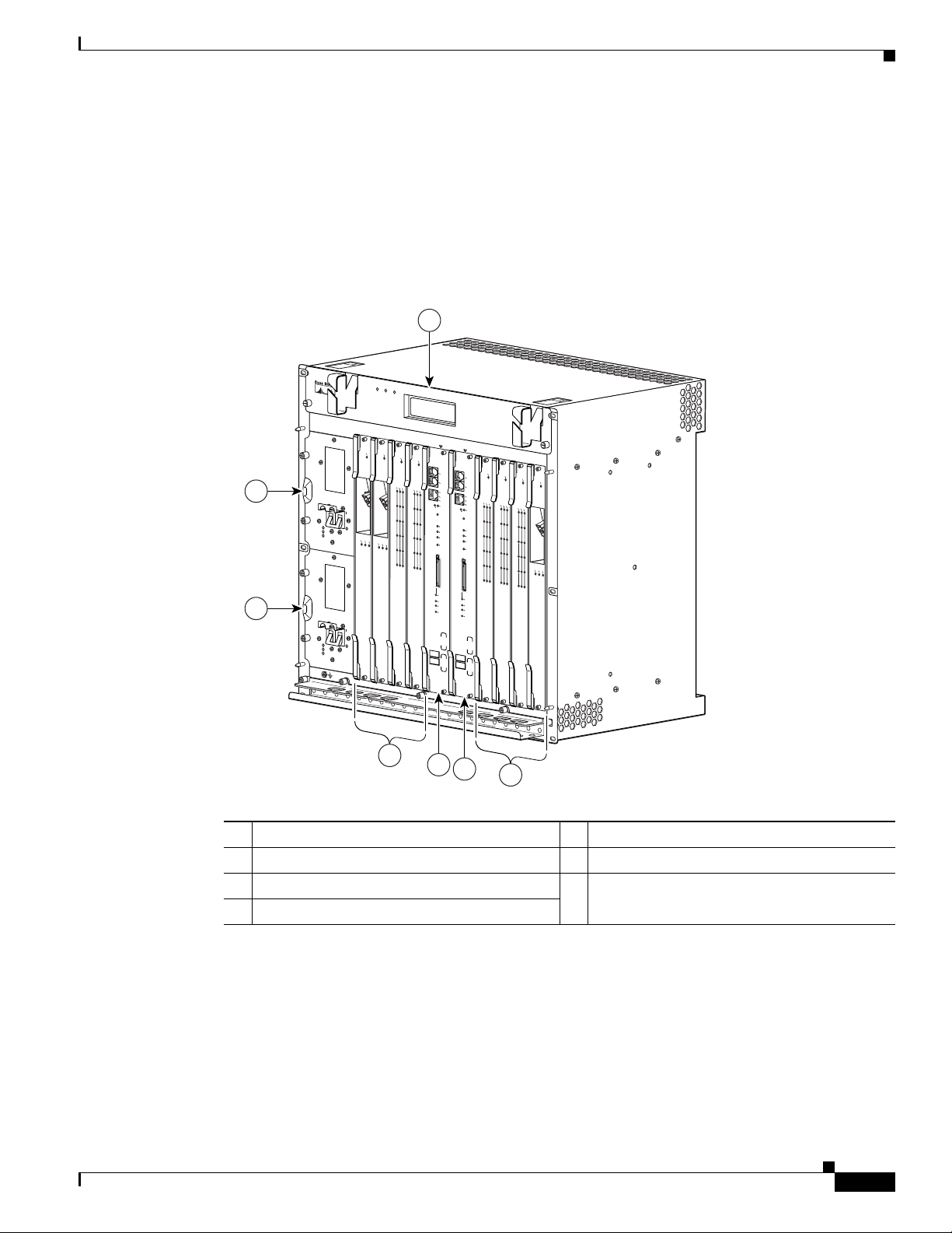
Figure 1 Cisco 10008 Router Chassis—Front View
2
3
MISWIRE
MISWIRE
Product Overview
1
FANS
FAN
OK
MULTI-
FAILURE
FAN
FAILURE
CAU
TIO
W
hen hot swapping this fan tray,
N
rem
oval and replacem
be don
e in u
en
t must
nder two m
system
shutdown will occur.
1
2
C
IS
C
O
C
ISC
1
0
0
O
0
0
10000
FAIL
F
A
IL
C
A
R
A
R
I
E
R
0
1
POWER
FAULT
POWER
FAULT
2
3
LINK
C
A
R
TX
A
RX
R
L
L
A
IE
O
R
R
O
M
P
4
5
GIGABIT ETHERNET
CH OC-12-DSO SM-IR
inutes or
3
4
0A
PR
O
C
0B
ESS
OR
O
N
C
ISC
O
C10000
C
ISC
10000
O
FAIL
1000
6CT3
0
FAIL
FA
IL
C
L
L
A
A
O
R
R
A
O
M
L
R
L
P
A
I
O
E
R
O
R
M
P
M
R
A
A
L
C
A
0
O
PORT0
L
1
PORT1
PORT2
2
PORT3
3
PORT4
4
PORT5
5
6XCT3–DS0
LY
5
C
IS
CO
100
00
CONSOLE
AUX
P
O
ACTIVITY
ETHERNET
LINK
A
L
C
IN
T
I
K
V
I
T
Y
ALARMS
C
R
I
T
IC
M
A
A
L
J
O
R
M
I
N
O
R
A
C
O
S
L
O
T
0
S
T
A
T
U
F
S
A
I
L
B
I
T
S
PERFORMANCE ROUTING ENGINE
6XCT3–DS0
P/N
ESR-PRE3
P
RO
C
ESSO
R O
6
7
C
IS
CO
10000
C10000
CISC
O
10000
6CT3
FAIL
FAIL
CONSOLE
AUX
C
A
ACTIVITY
R
A
L
R
L
A
IE
O
R
O
R
M
ETHERNET
P
M
R
P
A
A
L
O
C
A
0
O
PORT0
LINK
L
A
L
C
I
T
N
IV
K
IT
Y
1
PORT1
ALARMS
C
R
I
T
PO
2
RT2
IC
M
A
A
L
J
O
R
M
IN
O
R
PORT3
A
3
C
O
PORT4
4
PORT5
5
S
L
O
T
0
S
T
A
T
U
F
S
A
I
L
B
IT
S
PERFORMANCE ROUTING ENGINE
6XCT3–DS0
P/N
ESR-PRE3
8
C10000
CIS
C
O
C10000
CIS
10000
6CT3
CO
FA
C
10000
IS
6CT3
C
O
IL
FAIL
10000
F
AIL
FAIL
FAIL
C
A
R
A
L
R
C
L
A
IE
A
O
R
R
A
O
R
M
L
R
P
L
A
I
M
O
E
R
R
P
A
A
O
R
L
O
M
C
A
0
O
P
PORT0
L
M
R
P
A
A
L
O
C
A
0
O
PO
L
RT0
1
PORT1
1
PO
RT1
PO
2
RT2
PORT2
2
PORT3
3
PORT3
3
C
A
R
R
PORT4
IE
4
T
R
R
X
X
PO
RT4
4
PO
RT5
5
PORT5
5
OC–12/STM–4 POS SM–IR
6XCT3–DS0
6XCT3–DS0
NLY
OL-8544-01
4
5
6
7
132515
1 Blower module 5 PRE3—slot 0A
2 Primary Power Entry Module (PEM) 6 PRE3—slot 0B
3 Redundant PEM 7 Line card slots 5 to 8
4 Line card slots 1 to 4
The PRE3 performs all Layer 2 and Layer 3 packet manipulation related to routing and forwarding
through the Cisco 10008 router. Its advanced application-specific integrated circuit (ASIC) technology
supports very high performance throughput with IP services enabled on each port.
The PRE3 consists of two main logical and physical cards:
• The fast packet (FP) card—Performs fast path forwarding and output scheduling.
• The route processor (RP) card—Contains the configuration, management route processing engine,
and backplane interconnect. The FP card plugs into the RP card.
Cisco 10008 Router Performance Routing Engine 3 Installation
3
Page 4

Product Overview
The PRE3 runs Cisco IOS Release 12.2(31)SB2 and later releases. Benefits of the PRE3 include:
• 800-MHz dual processor
• Four PXF network processors arranged as 8 columns and 8 rows
• 128 Mbytes of configuration memory (per column) with Error-Correcting Code (ECC)
• 2 GB SDRAM with single error correction/double error detect ECC
• Two separate CompactFlash slots. The internal CompactFlash slot stores images to bootflash. The
• 256 MB packet buffer and 64 MB control memory ECC
• A 1000/100 Mbit Interprocess Ethernet interface for communications between redundant PRE3s
• A Hierarchical Queueing Framework (HQF) that provides a three level hierarchy for class, logic,
By centralizing packet processing in the PRE3, the Cisco 10008 router architecture frees up space on
line cards, enabling high interface density, yet retaining the compact Network Equipment Business
Systems (NEBS) transmission equipment form factor.
Redundant PRE3s
external CompactFlash slot is Disk0.
and physical levels
You can configure two PRE3s in a single chassis for redundancy. If the active PRE3 fails, the standby
PRE3 automatically takes over operation of the router. Because all the line cards are physically
connected to both the active and standby PRE3s, the failure of a single PRE3 does not require user
intervention. If a failure occurs, all line cards automatically reset to the redundant PRE3. Startup and
running configurations of the standby PRE3 are synchronized with the active PRE3, ensuring the fastest
possible cut-over time if the active PRE3 fails.
PRE3 Front Panel
This section describes the PRE3 front panel (see Figure 2).
PRE3 Connectors
The front panel on the PRE3 contains three ports with RJ-45 connectors (see Figure 2).
• Console port (CONSOLE)—This asynchronous serial port is used to connect a terminal to the PRE3
• Auxiliary port (AUX)—This asynchronous serial port is used to connect a modem to the PRE3 for
• Network Management Ethernet (NME) Port (ETHERNET)—This Ethernet port is used to connect
for local administrative access.
remote administrative access.
the PRE3 to a Fast Ethernet port.
CompactFlash Card Slot
The internal CompactFlash card slot can store the Cisco IOS image or a system configuration file on a
flash memory card. The system can also boot from the software stored on the flash memory card.
Cisco 10008 Router Performance Routing Engine 3 Installation
4
OL-8544-01
Page 5

Figure 2 PRE3 Front Panel
ETHERNET
AUX
10000
CISCO
CONSOLE
ACTIVITY
LINK
CRITICAL
ALARMS
MAJORMINORACO
SLOT 0
STATUS
Product Overview
PERFORMANCE ROUTING ENGINE
FAIL
BITS
P/N ESR-PRE3
149536
1 3 7 8
1 Ejector Levers 7 ACO (Alarm Cut-off Button)
2 Console and Auxiliary Ports 8 CompactFlash Slot, Disk0
3 Network Management Ethernet (NME) Port 9 Slot0 (Disk0) LED
4 Activity and Link LEDs 10 Status, Fail LEDs
5 Push-button reset 11 BITS LED
6 Alarms: Critical, Major, Minor 12 Alphanumeric Display
LED Indicators and Buttons
LEDs on the front panel of the PRE3 provide a visual indication showing the status of PRE3 operation.
Table 1 describes the PRE3 LEDs and buttons. Use Figure 2 and Tab l e 1 to understand the LEDs and
buttons.
Note F or additional information about alarm connections, see the Cisco 10000 Series Router
Performance Routing Engine Installation, at the following URL:
http://www.cisco.com/univercd/cc/td/doc/product/aggr/10000/hdwr/index.htm
Table 1 PRE3 LED Status and Button Descriptions
2 106 12
54
9
11
OL-8544-01
LEDs and Button Status Description
ACTIVITY Green Packets are being transmitted and received.
Off No activity.
LINK Green Carrier detected, the port is able to pass traffic.
Off No carrier detected, the port is not able to pass traffic.
Push-button reset n/a Resets the PRE3.
CRITICAL, MAJOR,
and MINOR LEDs
Off No alarm.
Note Alarm relay contacts can be used to connect the router
to an external visual or audio alarm system. This feature
enables any CRITICAL, MAJOR, or MINOR alarms
generated by the router to activate the visual or audible
alarms. Shutting off an audible alarm does not disable
the alarm LEDs.
Yellow Indicates an alarm condition.
ACO (Alarm cut–off)
n/a Pressing this button disables an audible alarm.
button
Cisco 10008 Router Performance Routing Engine 3 Installation
5
Page 6

Product Overview
Table 1 PRE3 LED Status and Button Descriptions (continued)
LEDs and Button Status Description
CompactFlash Disk0 Green Disk0 is active.
STATUS Flashing
FAIL Yellow A major failure has disabled the PRE3.
BITS n/a Not supported.
Alphanumeric Display
The alphanumeric display on the front panel provides information on the state of the PRE3. The display
consists of two four-character LED panels. Table 2 describes the most common messages. If you report
a problem to Cisco, it is helpful to include the message on the PRE3 alphanumeric display in your
problem report.
System is booting.
Yellow
Green PRE3 is active.
Flashing
PRE3 is standby.
Green
Off No power to PRE3.
Off The PRE3 is operating correctly.
Table 2 Messages on PRE3 Alphanumeric Display
Message PRE3 Status
1111, 2222, 3333, 4444, 5555, 6666,
7777
The PRE3 has just been powered on and is running its
power-on self-test.
ROM DONE The PRE3 has loaded the ROM monitor. This message
appears briefly if the system is configured to boot a Cisco
IOS software image. If the system is not configured to
boot Cisco IOS, this message remains on the display and
the rommon> prompt appears on the terminal window.
AUTO BOOT The ROM monitor is preparing to boot a Cisco IOS image.
BOOT IMGE A Cisco IOS image is starting to boot.
IOS STRT, IOS EXC, IOS FPGA, IOS
FPOK, IOS FILE, IOS STBY, IOS INTF,
These messages appear in quick succession during the
boot process.
IOS MEM, IOS DRVR, IOS LIB, IOS
MGMT, IOS PROT, IOS CONF
IOS RUN [On the primary PRE3] The PRE3 has finished booting
and is running Cisco IOS. This is the normal operating
status for the primary PRE.
IOS STBY [On the secondary PRE3] The PRE3 is in standby mode
and ready to take over if the primary PRE3 fails. This is
the normal operating status for the secondary PRE3.
Cisco 10008 Router Performance Routing Engine 3 Installation
6
OL-8544-01
Page 7

Prerequisites and Preparation
Before you perform any of the procedures in this guide, we recommend that you:
• Read the safety guidelines in the next section and review the electrical safety and ESD-prevention
guidelines as described in the hardware installation guide for the Cisco 10008 router.
Cisco 10008 Router Hardware Installation Guide
http://www.cisco.com/univercd/cc/td/doc/product/aggr/10000/hdwr/8-hig/index.htm
• Ensure that the software configuration meets the minimum requirements for the installation (see the
“Software Compatibility” section on page 8).
• Ensure that you have all of the necessary tools and equipment before beginning the installation (see
the “Installation Guidelines” section on page 8).
• Have a terminal console connected to the PRE3 to configure the PRE3 after it is installed.
The following documents may be used as reference material while performing procedures in this
document:
–
Cisco 10000 Series Router Performance Routing Engine Installation
http://www.cisco.com/univercd/cc/td/doc/product/aggr/10000/hdwr/index.htm
–
Cisco 10000 Series Internet Router Troubleshooting Guide
http://www.cisco.com/univercd/cc/td/doc/product/aggr/10000/tblshoot/trblgd/index.htm
Prerequisites and Preparation
Safety Guidelines
Before you begin the PRE3 installation procedure, review the safety guidelines in this section to avoid
injuring yourself or damaging the equipment. Before you install, configure, or perform maintenance on
the router, you should also review the safety warnings listed in the Regulatory Compliance and Safety
Information for Cisco 10000 Series Routers document.
Safety Warnings
Safety warnings appear throughout this publication in procedures that, if performed incorrectly, may
harm you. A warning symbol precedes each warning statement. The following warning is an example of
a safety warning. It identifies the warning symbol and associates it with a bodily injury hazard.
Warning
IMPORTANT SAFETY INSTRUCTIONS
This warning symbol means danger. You are in a situation that could cause bodily injury. Before you
work on any equipment, be aware of the hazards involved with electrical circuitry and be familiar
with standard practices for preventing accidents. Use the statement number provided at the end of
each warning to locate its translation in the translated safety warnings that accompanied this device.
Statement 1071
SAVE THESE INSTRUCTIONS
OL-8544-01
Note If you need translations of the safety warning, see the Regulatory Compliance and Safety Information
for Cisco 10000 Series Routers document.
Cisco 10008 Router Performance Routing Engine 3 Installation
7
Page 8

Software Compatibility
Software Compatibility
The PRE3 has specific Cisco IOS software requirements.
Table 3 shows the minimum required Cisco IOS software for the PRE3.
Table 3 PRE3 Software Compatibility
PRE3 Product Number Cisco IOS Release Minimum Cisco IOS Release
ESR-PRE3 12.2(31)SB2 12.2(31)SB2
Use the show version command to display the system software version that is currently loaded and
running.
If the output of the show version command indicates that the Cisco IOS software is a version earlier than
the version identified as the minimum Cisco IOS software release in Tab le 3, check the contents of the
CompactFlash memory to determine if the required images are available on your system.
The output of the show flash command provides a list of all files stored in the CompactFlash memory.
If the correct software version is not installed, contact Cisco Customer Service (see the “Obtaining
Technical Assistance” section on page 37).
Installation Guidelines
This section contains guidelines for the following:
• A new installation
• A replacement installation
• The required tools and equipment
The PRE3 is hot-swappable, which means you can remove and replace a PRE3 while the system is
operating—if you have a standby (redundant) PRE3 installed in the chassis. This feature allows you to
add, remove, or replace a PRE3 while the system maintains all routing information and ensures session
preservation.
Caution Replacing the active PRE3 in a non-redundant chassis (no standby PRE3) causes a system shutdown and
stops all traffic. If possible, alert all subscribers that the system will not be functioning during the
replacement.
Caution To prevent electrostatic discharge (ESD) damage, handle the PRE3 by the faceplate or the card carrier
edges only. Avoid touching the printed circuit board and its components, or any connector pins.
New Installation Guidelines
If you are replacing the PRE3 in a non-redundant system, you must configure the PRE3 using the
configure command. For configuration information, refer to the “Configuring a PRE3” section on
page 14.
Cisco 10008 Router Performance Routing Engine 3 Installation
8
OL-8544-01
Page 9

Replacement Installation Guidelines
If the PRE3 is replaced in a redundant system containing two PRE3s, the standby (or newly installed)
PRE3 automatically assumes the configuration of the active PRE3; do not configure the new PRE3.
Required Tools and Equipment
You need the following tools and equipment to install the PRE3:
• A 3/16-inch flat-blade screwdriver
• An ESD-preventive wrist or ankle strap with connection cord
• A terminal console to connect to the PRE3 after it is installed
Powering Off the System
If you are installing or replacing a single PRE3, power down the system using the following procedure:
Installation Guidelines
Caution If you have redundant Power Entry Modules (PEMs), set both power switches to the off (0) position. See
Figure 3 for the DC PEM power switch and Figure 4 for the AC PEM power switch.
Step 1 Attach an antistatic strap to your wrist or ankle and to an ESD socket on the chassis, or to a bare metal
surface on the chassis or frame.
Step 2 Set the power switch to the off (0) position.
Step 3 Go to the Installing or Replacing a PRE3, page 11.
OL-8544-01
Cisco 10008 Router Performance Routing Engine 3 Installation
9
Page 10
Installation Guidelines
Figure 3 Setting DC Power Switch to the Off Position
F
A
N
S
F
A
N
O
K
M
U
F
L
A
T
IL
I-
U
R
E
F
A
N
F
A
IL
U
R
E
C
AU
TIO
W
hen ho
N
t sw
appi
rem
oval a
ng this
nd replaceme
fan
b
tray,
e d
one
in und
nt m
system
u
er tw
st
o minu
shutdow
te
s o
n will oc
r
C
0
O
P
O
0
CH OC-12-DSO SM-IR
cur.
3
4
0A
PROCESSOR ONLY
C
IS
CO
1000
0
FA
IL
C
A
R
A
L
R
L
A
I
O
E
R
O
R
M
P
0
PORT0
1
PORT1
2
PORT
3
P
OR
4
PORT4
5
PORT5
6XCT3–DS0
0B
C10000
C
IS
C
O
10
00
0
6
CT3
FAIL
FAIL
C
A
R
A
L
R
L
A
I
O
E
R
O
R
M
P
M
P
A
LAR
C
A
0
OO
L
1
2
2
3
T3
4
5
6XCT3–DS0
5
T
PERFORMANCE ROUTING ENGINE
6
7
CISCO
10000
C
O
N
S
O
L
E
A
U
X
C
A
A
R
C
R
T
I
V
I
T
E
Y
T
H
E
R
0
PORT0
L
N
I
N
E
K
T
A
L
C
IN
T
IV
K
I
TY
1
P
OR
ALARMS
C
R
I
T
PORT2
2
IC
M
A
A
L
J
O
R
M
IN
O
R
PO
A
RT3
3
C
O
P
OR
4
T4
PORT5
5
S
L
O
T
0
S
T
A
T
U
F
S
A
I
L
B
I
T
S
PERFORMANCE ROUTING ENGINE
P/N
ESR-PRE3
8
C10000
CIS
CO
C100
C
1
ISC
00
00
00
O
6CT
3
1
0000
C10
C
ISC
6CT3
FAIL
000
O
1
00
FAIL
C
00
ISC
6CT3
O
1
0000
FAIL
FAIL
FAIL
F
AIL
FAIL
A
C
L
A
L
A
IE
O
R
A
R
L
R
O
R
C
M
L
A
IE
A
P
O
R
M
R
A
O
R
M
P
L
R
LAR
P
L
CA
A
A
I
O
E
LOO
R
O
R
LARM
OP
M
CA
A
0
P
PORT0
LO
M
R
A
OP
C
ALA
0
PORT0
LO
T1
1
PORT1
1
PORT1
PORT2
2
PO
2
RT2
PO
RT3
3
P
ORT3
3
C
A
R
R
PO
IE
RT4
4
T
R
R
X
X
PORT4
4
PORT5
5
POR
5
T5
OC–12/STM–4 POS SM–IR
6XCT3–DS0
6XCT3–DS0
6XCT3–DS0
CISCO
10000
C
O
N
S
O
L
E
A
U
X
A
C
T
I
V
I
T
E
Y
T
H
E
R
L
N
I
N
E
K
A
LI
C
T
N
IV
K
IT
Y
ALARMS
C
R
IT
I
C
M
A
A
L
J
O
R
M
I
N
O
R
A
C
O
S
L
O
T
0
S
T
A
T
U
F
S
A
I
L
B
I
T
S
P/N
ESR-PRE3
PROCESSOR ONLY
POWER
FAULT
MISWIRE
1
2
C
IS
C
O
1
0
C
0
0
IS
0
1
0
0
F
A
IL
F
A
IL
POWER
FAULT
MISWIRE
L
C
IN
A
R
T
A
K
R
R
X
L
X
L
A
IE
O
R
R
M
GIGABIT ETHERNET
POWER
FAULT
MISWIRE
Figure 4 Setting AC Power Switch to the Off Position
FAN
S
FAN
OK
MULTI-
FAILU
RE
FAN
FAILURE
C
A
U
T
W
IO
h
N
e
n
h
o
t s
w
a
r
e
p
m
p
in
o
v
g
a
th
l a
is
n
fa
d
re
n
b
tra
e
p
d
la
y
o
c
,
n
e
e
m
in
e
n
u
t m
n
s
d
y
u
e
s
s
r tw
te
t
m
o
s
m
h
u
in
td
u
o
te
w
s
n
o
w
r
ill o
c
c
u
r.
3
4
0
A
P
R
O
C
0
E
B
S
S
O
R
O
N
CISCO
10000
F
A
IL
CAR
AL
CARR
RIER
LOO
AR
M
P
0
0
P
O
R
1
1
P
O
R
2
P
2
O
R
3
P
O
R
3
4
P
O
R
4
5
P
O
R
5
6XCT3–DS0
L
Y
C
CISCO
10
0
0
0
10000
6
C
T
3
F
A
IL
F
A
IL
AL
L
ARM
IE
OO
R
P
M
R
P
A
A
O
C
AL
O
L
T
0
T1
T
2
T
3
T
4
T
5
6XCT3–DS0
5
C
IS
C
O
1
0
0
0
0
C
O
N
S
O
L
E
A
U
X
A
C
T
IV
IT
E
Y
T
H
E
R
L
N
IN
E
K
T
AC
LINK
TIV
ITY
A
LA
R
M
S
C
R
IT
IC
M
A
A
L
J
O
R
M
IN
O
R
A
C
O
SLOT
0
S
T
A
T
U
F
S
A
IL
B
IT
S
PERFORMANCE ROUTING ENGINE
P/N
ESR-PRE3
P
R
O
C
E
S
6
C
IS
C
O
1
0
0
0
0
LINK
A
LA
R
SLO
S
F
B
S
O
R
O
N
L
7
C
CISCO
1
00
0
0
C
CISCO
1
0
00
10000
6C
0
T
3
C
CISCO
1
10000
6
00
F
C
T
0
0
3
A
IL
F
10000
6
C
A
T
3
I
L
F
A
IL
F
AIL
C
O
N
F
A
IL
S
O
L
E
F
A
IL
A
U
X
CA
A
RRIER
A
CAR
C
LAR
T
LO
IV
ALA
IT
RIER
OP
CAR
M
LOO
E
Y
T
RM
M
A
H
R
P
E
A
LARM
RIER
A
L
P
O
LOO
C
R
A
0
M
P
L
O
LO
N
R
R
T
IN
0
P
A
A
E
L
O
C
K
T
A
0
O
P
P
O
L
R
T
M
0
P
AR
A
L
O
C
A
0
ACTIVITY
P
O
LO
R
T
0
1
P
O
R
T1
1
P
O
R
T
1
1
P
O
R
T
1
M
S
C
R
IT
P
2
O
R
IC
T
2
M
A
P
2
O
R
T
2
A
L
J
O
PO
2
R
T
2
R
M
IN
O
R
P
O
A
R
3
T
3
C
P
O
O
R
3
T
3
P
O
R
3
T
3
P
O
R
4
T
4
P
O
R
4
T
4
P
O
R
4
T
4
P
O
R
5
T
5
P
O
R
5
T
5
P
O
R
5
T
5
T 0
T
A
T
U
S
A
IL
IT
S
PERFORMANCE ROUTING ENGINE
6XCT3–DS0
6XCT3–DS0
6XCT3–DS0
P/N
ESR-PRE3
Y
POWER
FAULT
1
2
C
I
S
C
O
C
IS
1
C
0
0
O
0
0
1
0
0
0
0
FA
IL
F
A
IL
POWER
FAULT
L
C
INK
A
R
TX
A
R
R
L
X
L
A
I
E
O
R
R
O
M
P
GIGABIT ETHERNET
CH OC-12-DSO SM-IR
POWER
FAULT
30019
8
CISCO
10000
F
A
I
L
CA
RRIER
TX
RX
OC–12/STM–4 POS SM–IR
10
30026
Cisco 10008 Router Performance Routing Engine 3 Installation
OL-8544-01
Page 11

Installing or Replacing a PRE3
This section describes how to install or replace the PRE3 in the Cisco 10008 chassis. It contains the
following information:
• Installing a PRE3, page 11
• Configuring a PRE3, page 14
• Removing a PRE3, page 14
• Troubleshooting the Installation, page 15
Installing a PRE3
Use the following procedure to install the PRE3 into slot 0A or slot 0B in the Cisco 10008 chassis.
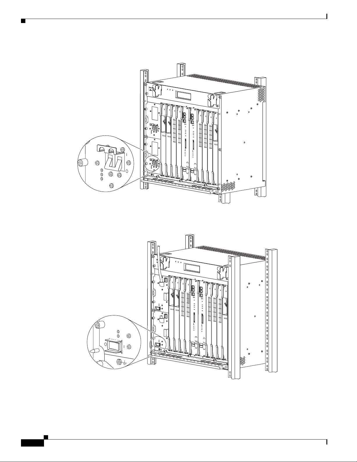
Step 1 Attach an antistatic strap to your wrist or ankle and to an ESD socket (see Figure 5) on the chassis, or to
a bare metal surface on the chassis or frame.
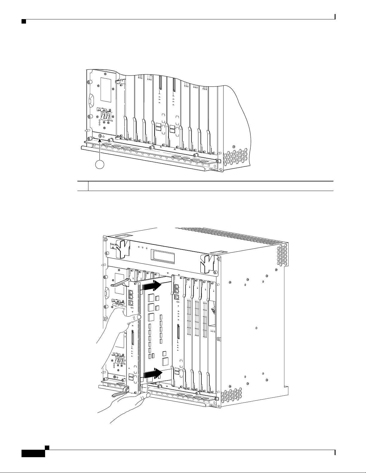
Step 2 Grasp the faceplate (see Figure 6) of the PRE3 with one hand and place your other hand under the frame
of the PRE3 to support the weight of the PRE3. Position the PRE3 in front of the chassis slot.
Installing or Replacing a PRE3
Step 3 Carefully align the upper and lower edges (see Figure 6) of the PRE3 with the upper and lower guides
in the chassis, and slide the PRE3 into the slot until you can feel it begin to seat in the backplane
connectors.
Step 4 Simultaneously pivot both ejector levers (see Figure 7) toward each other, until they are parallel to the
faceplate, to firmly seat the PRE3 in the backplane.
The PRE3 cycles through its power-on self-test. The FAIL LED stays on briefly (10 to 15 seconds) and
then shuts off.
Step 5 Tighten the top and bottom captive screws (see Figure 8) to secure the PRE3 to the chassis.
Caution To ensure that there is adequate space for additional line cards, always tighten the captive
screws on each newly installed PRE3 before you insert a standby PRE3 or any additional line
cards. The captive screws prevent accidental removal and provide proper grounding for EMI
shielding.
Step 6 Refer to the “Configuring a PRE3” section on page 14 for information about configuring the PRE3.
OL-8544-01
Cisco 10008 Router Performance Routing Engine 3 Installation
11
Page 12
Installing or Replacing a PRE3
Figure 5 ESD Chassis Connection
POWER
FAULT
MISWIRE
5
5
5
CISCO
10000
S
L
O
T
0
S
T
A
T
U
F
S
A
IL
B
IT
6XCT3–DS0
S
PERFORMANCE ROUTING ENGINE
F
A
IL
P/N
ESR-PRE3
CH OC-12-DSO SM-IR
6XCT3–DS0
5
5
S
L
O
T
0
S
T
A
T
U
F
S
A
IL
B
IT
S
P/N
ESR-PRE3
PERFORMANCE ROUTING ENGINE
6XCT3–DS0
6XCT3–DS0
OC–12/STM–4 POS SM–IR
6XCT3–DS0
PROCESSOR ONLY
1
1 ESD socket
Figure 6 Inserting and Removing the PRE3
F
A
N
S
F
AN
M
O
U
K
L
TIF
A
IL
U
R
E
FA
N
F
A
IL
U
R
E
CAUTION
When hot swapping this fan tray,
removal and replacement must
be done in under two minutes or
system shutdown will occur.
1
2
3
4
0A
PROCESSOR ONLY
0B
ALARMS
5
CISCO
10000
LINK
SLOT 0
STATUS
FAIL
BITS
6
C
IS
C
O
C
IS
C
100
O
0
0
10
0
F
00
AIL
FA
IL
C
O
N
S
O
L
E
A
U
X
C
A
AC
R
A
C
L
R
T
A
L
A
IVITY
I
O
R
A
E
R
L
R
O
R
C
M
L
E
A
IE
A
P
O
T
R
H
O
R
M
E
P
R
0
LIN
N
E
K
T
0
ACTIVITY
C
RITIC
M
AL
AJOR
M
INO
R
AC
O
PERFORMANCE ROUTING ENGINE
P/N
ESR-PRE3
0
1
1
1
2
2
2
3
3
3
4
4
4
5
5
5
6XCT3–DS0
6XCT3–DS0
C
O
C
IS
C
00
O
1
0
000
FAIL
C
A
R
A
L
R
L
P
A
IE
O
R
O
R
M
P
0
1
2
3
4
5
6XCT3–DS0
6XCT3–DS0
PROCESSOR ONLY
POWER
MISWIRE
POWER
MISWIRE
C
IS
C
O
CISCO
1
0000
C
IS
10000
FA
IL
10
F
0
A
I
L
F
AIL
CISCO
C
IS
C
O
10000
10
00
0
C
A
R
A
L
R
L
A
IE
O
R
O
R
M
0
C
CONSOLE
O
N
S
O
LE
AU
AUX
X
1
A
ACTIVITY
C
T
IV
IT
E
ETHERNET
Y
T
H
E
SLO
SLO
R
LIN
LINK
N
E
T
K
T
T
2
0
1
ACTIVITY
FAULT
FAULT
LINK
3
LINK
C
A
ALARMS
R
TX
A
R
R
L
X
L
A
IE
O
R
R
O
M
C
P
R
IT
IC
M
AL
4
A
JO
R
M
IN
O
R
AC
O
5
SLOT 0
GIGABIT ETHERNET
S
TATU
CH OC-12-DSO SM-IR
FAIL
S
B
ITS
PERFORMANCE ROUTING ENGINE
ACO
CRITICAL
PERFORMANCE ROUTING ENGINE
MAJOR
MINOR
STATUS
FAIL
P/N
ESR-PRE3
126144
7
8
C
IS
C
O
C
1
IS
00
C
00
O
10
F
0
00
AIL
F
A
IL
R
A
L
R
L
A
IE
O
R
O
R
M
P
C
A
R
R
IE
T
R
R
X
X
OC–12/STM–4 POS SM–IR
6XCT3–DS0
12
32682
Cisco 10008 Router Performance Routing Engine 3 Installation
OL-8544-01
Page 13

Figure 7 Closing and Opening the PRE3 Ejector Levers
F
A
N
S
FA
N
MU
OK
LTI-
F
A
IL
UR
E
FA
N
FAIL
U
RE
C
A
U
T
W
IO
he
N
n h
o
t s
w
a
re
pp
m
in
o
v
g th
al an
is
fa
d rep
n tra
b
e
do
la
y
ce
,
ne
m
in un
e
n
t m
sys
d
us
e
r tw
te
t
m
o
shu
m
in
td
ute
o
w
s o
n
w
r
ill oc
cu
r.
4
0A
PROCESSOR ONLY
0B
Y
PERFORMANCE ROUTING ENGINE
ALARMS
5
6
7
C
ISCO
10000
CISCO
10000
FAIL
CONSOLE
AUX
CA
ACTIVITY
RR
A
LAR
LO
IE
OP
R
M
ETHERNET
0
LINK
A
L
C
IN
T
IV
K
ITY
1
CR
ITICA
2
M
AJOR
L
M
INOR
ACO
3
4
5
S
L
O
T
0
STATU
FAIL
S
BITS
PERFORMANCE ROUTING ENGINE
6XCT3–DS0
P/N
ESR-PRE3
8
CISCO
10000
CISCO
FAIL
CISCO
10000
FAIL
10000
FAIL
CA
RR
A
LA
C
L
IER
AR
OO
RM
AL
R
P
LO
AR
IER
O
M
0
P
0
1
1
2
2
3
3
C
AR
R
IE
4
TX
R
RX
4
5
5
OC–12/STM–4 POS SM–IR
6XCT3–DS0
6XCT3–DS0
CISCO
CISCO
10000
FAIL
10000
CONSOLE
CARRIER
AUX
A
LARM
LOOP
0
ACTIVITY
ETHERNET
LINK
A
1
L
C
IN
T
IV
K
IT
ALARMS
2
C
RITICAL
MAJO
3
R
M
INO
R
ACO
4
5
S
L
O
T
0
STATUS
FAIL
BITS
6XCT3–DS0
6XCT3–DS0
P/N
ESR-PRE3
PROCESSOR ONLY
MISWIRE
MISWIRE
1
2
3
CISCO
C
10000
IS
C
O
CISCO
1
0
0
F
00
A
IL
10000
F
A
IL
FAIL
CA
RRIER
ALA
LOOP
RM
0
1
POWER
FAULT
2
3
L
C
I
A
N
R
T
A
K
R
R
X
L
X
L
A
IE
O
R
R
O
M
P
4
5
GIGABIT ETHERNET
CH OC-12-DSO SM-IR
POWER
FAULT
CISCO
C10000
10000
PRE
CONSOLE
AUX
ACTIVITY
ETHERNET
SLOT 0
SLOT 1
LINK
PROCESSOR ONLY
Installing or Replacing a PRE3
CISCO
10000
CONSOLE
AUX
AC
32683
OL-8544-01
Cisco 10008 Router Performance Routing Engine 3 Installation
13
Page 14

Installing or Replacing a PRE3
Figure 8 PRE3 Captive Screw Locations
MISWIRE
POWER
MISWIRE
POWER
FAULT
FAULT
FANS
FAN
OK
MULTI-
FAILURE
FAN
FAILURE
1
2
C
ISCO
C10000
C
10000
ISC
C10000
O
1GE
1
0
ChCO12
000
F
A
IL
F
A
IL
F
AIL
F
AIL
PORT0
PORT1
PORT2
PORT3
L
C
IN
A
R
T
A
K
R
R
X
L
X
L
A
I
E
O
R
R
O
M
P
CA
OP
ALARM
LO
LIN
K
TX
RX
PORT4
PORT5
GIGABIT ETHERNET
CH OC-12-DSO SM-IR
C
A
U
T
W
IO
h
N
e
n
h
o
t s
w
a
re
p
m
p
in
o
v
g
a
th
l a
is
n
fa
d
re
n
b
tr
e
p
d
la
a
y
o
c
,
n
e
e
m
in
e
n
u
t m
n
s
d
y
u
e
s
s
r tw
te
t
m
o
s
m
h
u
in
td
u
o
te
w
s
n
o
w
r
ill o
c
c
u
r
.
3
4
0A
PROCESSOR
C
IS
C
10000
C
O
C
1
IS
C
0
100
C
0
6C
0
O
0
T3
00
C
1
FAIL
0
IS
0
6C
C
0
O
0
T3
FAIL
10
0
FAIL
C
A
R
A
L
R
L
A
IE
O
R
O
R
M
0
CA
ALARM
1
2
3
4
5
00
FAIL
C
A
R
A
L
R
L
P
A
IE
O
R
O
R
M
OP
P
LO
ARM
0
CA
AL
OOP
PORT0
L
1
PORT1
LINK
ALARMS
2
PORT2
PORT3
3
PORT4
4
PORT5
5
SLOT 0
STATUS
FAIL
BITS
6XCT3–DS0
6XCT3–DS0
PROCESSOR
CRITICAL
M
MIN
ACO
C
ON
AUX
A
CTIV
ETHER
LIN
K
ACTIVITY
AJO
OR
P/N
ESR-PRE3
SOLE
ITY
NET
R
PERFORMANCE ROUTING ENGINE
C
1
ALARMS
1
IS
C
O
00
0
0
CONSOLE
AU
X
ACTIVITY
ETHER
LINK
NET
ACTIVITY
LINK
CRITICAL
M
AJOR
MINOR
ACO
SLOT 0
STATUS
FAIL
BITS
PERFORMANCE ROUTING ENGINE
P/N
ESR-PRE3
1
1 Captive screws
Configuring a PRE3
After the PRE3 is successfully installed, you can configure it for network use. For information about
configuring the PRE3, see “Managing the Router Using the Network Management Ethernet Port” section
on page 24.
Note You do not need to configure a redundant (secondary) PRE3. The standby PRE3 automatically assumes
the configuration of the active PRE3.
Removing a PRE3
Use the following procedure to remove a PRE3 from the chassis:
Step 1 Attach an antistatic strap to your wrist or ankle and to an ESD socket (see Figure 5) on the chassis, or to
a bare metal surface on the chassis or frame.
132833
14
Cisco 10008 Router Performance Routing Engine 3 Installation
OL-8544-01
Page 15

Installing or Replacing a PRE3
Step 2 Loosen the top and bottom captive screws (see Figure 8) on the PRE3.
Note The top and bottom captive screws must be loosened prior to pivoting the ejector levers in Step 3.
Step 3 Simultaneously pivot both ejector levers (see Figure 7) away from each other to disengage the PRE3
from the backplane.
Step 4 Slide the PRE3 out of the slot (see Figure 6) and place it on an antistatic surface, or in an antistatic bag.
Step 5 See the “Installing or Replacing a PRE3” section on page 11 for instructions on how to install a new
PRE3.
Note If you are not installing a replacement PRE3, install a blank faceplate in the slot.
Warning
Step 6 Power on the system if you have powered it off.
Do not operate the system unless all slots contain a PRE3, line card, or a blank faceplate. Blank
faceplates are necessary in empty slots to prevent exposure to hazardous voltages, to reduce
electromagnetic interference (EMI) that may disrupt other equipment, and to direct the flow of cooling
air through the chassis.
Troubleshooting the Installation
Refer to Figure 2 and Table 1 for descriptions of the LEDs on the PRE3. Follow the instructions in
Table 4 to troubleshoot the installation.
Table 4 PRE3 Installation Troubleshooting
Symptom Possible Cause Corrective Action
PEMs, fans, and other line cards
do not operate
1. Disconnected power cord.
2. Power switch is in the Off
position.
3. The PRE3 fuses are blown.
1. Check that all power cords
are properly connected to
both the chassis and at the
power connection end.
2. Set the PEM power
switches to the On
position.
OL-8544-01
3. Replace the PRE3.
Cisco 10008 Router Performance Routing Engine 3 Installation
15
Page 16

Forcing Failover in a Redundant Pair
Symptom Possible Cause Corrective Action
The FAIL LED does not light
during the power-on self-test
PRE3 does not operate properly
If these troubleshooting procedures do not correct the problem, refer to the Cisco 10000 Series Router
Troubleshooting Guide for additional information.
1. The PRE3 is not properly
seated.
2. Bad PRE3 slot or backplane
connector.
1. Bad PRE3 slot or backplane
connector.
2. Bad PRE3.
1. Be sure the ejector levers
are fully closed and that
the captive screws have
been tightened.
2. Remove the PRE3 and
install it in another PRE3
slot.
1. Remove the PRE3 and
install it in another PRE3
slot.
2. Replace the PRE3.
Forcing Failover in a Redundant Pair
To manually force the active and standby devices in a redundant pair to failover, use the redundancy
force-failover command. Manually force the active and standby PRE3s to reverse roles if you need to
replace the active one. You can then replace the PRE3 while causing only minimal disruption of traffic.
The following example shows how to set the standby PRE3 to be active:
Router# redundancy force-failover main-cpu
This command does not generate an alarm.
Managing System Boot Parameters
During the boot process, the system reads a software configuration register that defines certain system
parameters. The software configuration register is a 16-bit register in NVRAM used to define such
characteristics as:
• The source of the Cisco IOS software image required to run the router
• Whether the system software should ignore the contents of NVRAM
• The behavior of the Break function
By modifying the boot parameters, you can customize your Cisco 10008 router. For example, a common
configuration register setting in some lab environments is 0x2100. Using this setting, the system boots
to the ROM monitor (ROMmon) prompt, where a technician can load a specific image by entering the
boot command at the ROMmon prompt.
16
Cisco 10008 Router Performance Routing Engine 3 Installation
OL-8544-01
Page 17

Changing the Software Configuration Register Settings
The factory default value for the software configuration register is 0x2102. This value is a combination
of the following: binary bit 8 = 0x0100, bits 00 through 03 = 0x0002, and bit 13 = 2000.
To change the software configuration register settings while you are running system software, perform
the following steps:
Step 1 From global configuration mode, enter the config-register value command to set the contents of the
software configuration-register; value is a hexadecimal number preceded by 0x, for example:
Router(config)# config-register 0x2100
Consult the hexadecimal column in Table 5 on page 18 for the possible settings to enter as the 4-bit value
parameter.
Step 2 Exit global configuration mode by pressing Ctrl-Z.
Router(config)# Ctrl-Z
Router#
Step 3 To display the new software configuration register setting, issue the show version command.
Router# show version
.
.
.
#Configuration register is 0x141 (will be 0x2100 at next reload)
Managing System Boot Parameters
Step 4 Save the configuration file to preserve the new software configuration register settings.
Router# copy running-config startup-config
Step 5 Reboot the router.
The router reboots using the new register settings. The software configuration register setting takes
affect only after you reload the system. This happens when you issue the reload command from the
console or reboot the router.
OL-8544-01
Cisco 10008 Router Performance Routing Engine 3 Installation
17
Page 18

Upgrading Software
Table 5 Definition of Bits in the Software Configuration Register
Bit No. Hex Value Meaning/Function
00 to 03 0x0000 to 0x000F Defines the source of a default Cisco IOS software image required to run the router:
• 00—At power-on, the system remains at the ROM monitor prompt (rommon>),
awaiting a user command to boot the system manually by means of the ROMmon
boot command.
• 01—At power-on, the system automatically boots the first system image found on
the PRE3.
• 02 to 0F—At power-on, the system automatically boots from a default Cisco IOS
software image stored on a TFTP server in the network. For this setting, the
Fast Ethernet port on the PRE3 must be configured and operational. This setting
also enables boot system commands that override the default filename.
06 0x0040 Causes system software to ignore the contents of NVRAM.
07 0x0080 Enables the original equipment manufacturer (OEM) bit.
08 0x0100 The Break function is disabled after 30 seconds.
09 0x0200 Not used.
10 0x0400 Broadcast based on 0.0.0.0 IP address.
11 and 12 0x0800 to 0x1000 Defines the console baud rate (the default setting is 9600 baud).
13 0x2000 Boots an image from Disk0.
14 0x4000 Broadcast using the subnet broadcast address.
15 0x8000 Enables diagnostic messages and ignores the contents of NVRAM.
Upgrading Software
This section describes the following methods for upgrading Cisco IOS images on the Cisco 10008
router:
• Upgrading Software from a PRE2 to a PRE3, page 18
• Upgrading Software on a Single PRE3, page 21
• Upgrading Software on Redundant PRE3s, page 22
Upgrading Software from a PRE2 to a PRE3
This section describes the procedures for upgrading the Performance Routing Engine from a PRE2 to a
PRE3. Procedures for downgrading from a PRE3 to a PRE2 are also described.
• Prerequisites, page 19
• Upgrade Considerations, page 19
• Procedure to Upgrade a PRE2 to a PRE3, page 19
Note When upgrading from a PRE2, all references to boot commands pointing to disk1 should be removed.
PRE3 has one slot, Disk0.
18
Cisco 10008 Router Performance Routing Engine 3 Installation
OL-8544-01
Page 19

Prerequisites
For all of the software features supported by your current PRE2 (c10k2-p11-mz) image to function
correctly, they must be supported by the PRE3 image. Check with the Cisco Technical Assistance Center
(TAC) to verify the correct upgrade path before initiating the upgrade.
The upgrade should be performed by a qualified engineer. This person must be familiar with the Cisco
router console interface and be able to perform basic router operations, such as configuration loading
and router reload functions.
Caution Do not perform this upgrade if your current PRE2 software image supports new features not yet
supported by the PRE3 software image. Performing this upgrade will cause these features to fail.
Upgrade Considerations
• This is a service impacting hardware upgrade. The router will not be available for user traffic during
the upgrade, and traffic cannot resume until the upgrade is complete.
• All new PRE3s are shipped with an eboot image (c10k3-eboot-mz) stored in bootflash.
Upgrading Software
Procedure to Upgrade a PRE2 to a PRE3
Follow this procedure to upgrade a single PRE2 in a Cisco 10008 chassis that does not have a redundant,
standby PRE2.
Step 1 Connect a terminal to the active PRE2.
Step 2 Save the startup and running configuration to a location on a TFTP server.
Caution When the PRE2 is removed from the chassis, any local configuration will be lost. You must
save your configuration to a TFTP server.
Step 3 Power down the router. All the traffic on the router is stopped.
Note PRE2s can be hot-swapped. However, because removing a PRE2 stops all traffic, we recommend
that you power down the router to ensure a successful installation.
Step 4 Attach an antistatic strap to your wrist or ankle and to an ESD socket on the chassis, or to a bare metal
surface on the chassis or frame.
Step 5 Remove the PRE2 from the chassis using the procedure in the “Removing a PRE3” section on page 14.
Step 6 Insert the PRE3 into slot 0A of the chassis by following the procedure in the “Installing a PRE3” section
on page 11.
OL-8544-01
a. If you do not have a second, redundant PRE3 to install, a blank card must be used to fill the unused
slot 0B.
Note Although a PRE3 can be installed in slot 0B, we recommend that you install a single,
non-redundant PRE3 in slot 0A to ensure proper operation.
Cisco 10008 Router Performance Routing Engine 3 Installation
19
Page 20

Upgrading Software
Step 7 Power up the router. The router boots in read-only memory (ROM) monitor mode.
Step 8 From the console in ROM monitor mode, enter the appropriate boot command.
Booting from a TFTP Server
If you saved the PRE2 image on a TFTP server that is reachable from the router (for example, if the
router and server are on the same LAN or there is a default proxy server), boot the router from the TFTP
server.
In the following example, the router boots the PRE3 image from a network server with the IP address
172.16.15.112:
> boot tftp://172.16.15.112/c10k3-p11-mz
The configuration dialog appears.
You can now proceed to step 9.
Booting from Disk0
If the image was saved to Disk0, boot that image.
The following boot command loads the PRE3 image from Disk0:
> boot disk0:c10k3-p11-mz
The configuration dialog appears.
You can now proceed to step 9.
Booting from the eboot Image
If you did not save the PRE3 image to a TFTP server, boot the eboot (c10k3-eboot-mz) image stored in
bootflash.
In the following example, the router boots from the eboot image:
> boot bootflash:c10k3-eboot-mz
The configuration dialog appears.
Proceed to the “Did Not Save the Configuration” section on page 21.
Step 9 Restore the startup and running configuration of the router.
Saved the Configuration on a CompactFlash Card
If you booted the PRE3 image and saved the previous configuration to a CompactFlash card:
a. Exit the configuration dialog and restore the previously saved startup and running configuration
from the CompactFlash card.
b. Update any boot commands to use the new PRE3 image.
The router is available for normal operations and the upgrade is complete.
20
Cisco 10008 Router Performance Routing Engine 3 Installation
OL-8544-01
Page 21

Upgrading Software
Saved the Configuration on a TFTP Server
If you booted the PRE3 image, and you saved the previous configuration to a TFTP server:
a. Enter the initial configuration dialog, and enter all required information to allow access to the TFTP
server.
b. Assign the correct IP address for the Fast Ethernet interface to become active and for the TFTP
server to become reachable. This may require adding an IP route for the server even after the initial
dialog completes.
c. Restore the previous configuration from the TFTP server to the startup and running configuration
on the router.
d. Restore the startup and running configuration and update any boot commands to use the new PRE3
image.
The router is available for normal operations and the upgrade is complete.
Did Not Save the Configuration
If you did not save the PRE2 image to a TFTP server and you booted the PRE3 image:
a. Enter the initial configuration dialog, and enter all required information. Be sure to assign the
correct IP address for the Fast Ethernet interface to become active and for the TFTP server to become
reachable.
b. The TFTP server should be reachable. If you wish to boot the PRE3 image from a local
CompactFlash card, download the PRE3 IOS image from the TFTP server to the bootflash memory.
If you wish to boot directly from the TFTP server, you can skip the image download.
c. Restore the previously saved configuration by downloading it from the TFTP server. Update any
boot commands from the previous configuration to point to the new PRE3 image. Otherwise, update
the boot command to point to the desired PRE3 image.
d. Reload the router. After reload, the router is available to resume normal operations and the upgrade
is complete.
Upgrading Software on a Single PRE3
To upgrade software for a single PRE3, follow these steps:
Step 1 Copy the Cisco IOS image from a TFTP server to Disk0.
Router# copy tftp disk0:
Address or name of remote host []? 223.255.254.254
Source filename []? pre3/images/c10k3-p11-mz
Destination filename [c10k3-p11-mz]?
Accessing tftp://223.255.254.254/pre3/images/c10k3-p11-mz...
Loading pre3/images/c10k3-p11-mz from 223.255.254.254 (via FastEthernet0/0/0):
.
.
.
.
[OK - 25251732 bytes]
25251732 bytes copied in 50.356 secs (501464 bytes/sec)
Router#
OL-8544-01
Step 2 Tell the Cisco 10008 router the location in which the new boot image resides. In the following example,
the system is told that the image “c10k3-p11-mz” is located in Disk0.
Router(config)# boot system flash disk0:c10k3-p11-mz
Cisco 10008 Router Performance Routing Engine 3 Installation
21
Page 22

Upgrading Software
Step 3 Copy the running configuration to the startup configuration.
Router# copy running-config startup-config
Step 4 Reload the software by entering the reload command.
Router# reload
The system is now using the new Cisco IOS image.
Upgrading Software on Redundant PRE3s
To upgrade software for redundant PRE3s, follow these steps:
Step 1 Verify both PRE3s are up using the show redundancy states command.
Router# show redundancy states
my state = 13 -ACTIVE
peer state = 8 -STANDBY HOT
Mode = Duplex
Unit = Primary
Unit ID = 0
Redundancy Mode (Operational) = SSO
Redundancy Mode (Configured) = SSO
Redundancy State = SSO
Maintenance Mode = Disabled
Manual swact enabled
Communications = Up
client count = 38
client_notification_TMR = 30000 milliseconds
RF debug mask = 0x0
Step 2 Copy the Cisco IOS image from a TFTP server to Disk0 on the active PRE3.
Router# copy tftp disk0:
Address or name of remote host []? 223.255.254.248
Source filename []? c10008/c10k3-p11-mz
Destination filename [c10k3-p11-mz]?
Accessing tftp://223.255.254.248/c10008/c10k3-p11-mz...
Loading c10008/c10k3-p11-mz from 223.255.254.248(via FastEthernet0/0/0):
!!!!!!!!!!!!!!!!!!!!!!!!!!!!!!!!!!!!!!!!!!!!!!!!!!!!!!!!!!!!!!!!!!!!!!...
[OK - 25750196 bytes]
25750196 bytes copied in 50.64 secs (508495 bytes/sec)
Step 3 Copy the Cisco IOS image from a TFTP server to Disk0 on the standby PRE3.
Router# copy tftp stby-disk0
The output is similar to that shown in the previous step.
22
Step 4 Verify the Cisco IOS image is in the Disk0 directories.
Router# dir disk0:
Directory of disk0:/
1 -rw- 25750196 Mar 4 2000 00:13:24 +00:00 c10k3-p11-mz
Cisco 10008 Router Performance Routing Engine 3 Installation
OL-8544-01
Page 23

256503808 bytes total (230752256 bytes free)
Router# dir stby-disk0:
Directory of stby-disk0:/
1 -rw- 25750196 Mar 4 2000 00:14:56 +00:00 c10k3-p11-mz
257544192 bytes total (231792640 bytes free)
Step 5 Display the system image on bootflash.
Router# show run | i boot
boot-start-marker
boot system flash disk0:c10k3-p11-mz.mce_rp_isp-20060127
boot-end-marker
exception crashinfo file bootflash:crashinfo
Step 6 Enter global configuration mode.
Router# configure terminal
Enter configuration commands, one per line. End with CNTL/Z.
Router(config)#
Step 7 Remove the current image from bootflash in Disk0.
Router(config)# no boot system flash disk0:c10k3-p11-mz.mce_rp_isp-20060127
Upgrading Software
Step 8 Add the new image to bootflash in Disk0.
Router(config)# boot system flash disk0:c10k3-p11-mz
Step 9 Set the contents of the software configuration register to 0x2100. This new register setting will take
affect after the system reload in Step 13.
Router(config)# config-register 0x2100
Step 10 Return to privileged EXEC mode.
Router(config)# exit
Router#
Step 11 Copy the running configuration to the startup configuration.
Router# copy running-config startup-config
Destination filename [startup-config]?
Building configuration...
[OK]
Step 12 Verify the running configuration is copied to the startup configuration on both PRE3s.
Router# show bootvar
BOOT variable = disk0:c10k3-p11-mz,1;
CONFIG_FILE variable =
BOOTLDR variable =
Configuration register is 0x0
Standby BOOT variable = disk0:c10k3-p11-mz,1;
Standby CONFIG_FILE variable =
Standby BOOTLDR variable =
Standby Configuration register is 0x0
OL-8544-01
Step 13 Reload the system by entering the reload command.
Router# reload
Proceed with reload? [confirm]
Cisco 10008 Router Performance Routing Engine 3 Installation
23
Page 24

Managing the Router Using the Network Management Ethernet Port
Resetting .......
.
.
.
Both PRE3s are now using the new Cisco IOS image with the new register settings.
Managing the Router Using the Network Management Ethernet
Port
The network management Ethernet (NME) port on the PRE3 is used to manage the Cisco 10008 router.
The duplex mode and speed of the NME port are configurable.
The following sections describe how to configure the duplex mode and speed of the NME port for the
PRE3.
Configuring the NME Port on the PRE3
The NME port for PRE3 supports the following operational modes:
• Autonegotiation (the default)
• Full-duplex
• Half-duplex
Default configurations do not appear in the router’s configuration file.
We recommend that you allow the NME port to autonegotiate the duplex mode. When autonegotiation
mode is enabled, the NME port responds only to IEEE 802.3x pause frames from another device.
If the negotiation of duplex mode fails and a duplex mode mismatch occurs, manually set the duplex
mode for full-duplex or half-duplex operation. Setting duplex mode disables autonegotiation mode.
When you manually set duplex mode, the NME port does not support IEEE 802.3x flow control.
When you manually configure duplex mode, the NME port can experience problems. If this occurs,
disable duplex mode by entering the no full-duplex or no half-duplex command. When you enter the
no duplex command, the operational mode reverts to autonegotiation mode.
To configure the NME port, perform the following optional configuration tasks:
• Manually Setting the Duplex Mode for the NME Port for the PRE3, page 24
• Manually Setting the Speed for the NME Port for the PRE3, page 25
Manually Setting the Duplex Mode for the NME Port for the PRE3
24
Note We recommend that you allow the NME port to autonegotiate (default setting) duplex mode.
To manually set the duplex operational mode of the NME port for the PRE3, enter either of the following
commands in interface configuration mode:
Cisco 10008 Router Performance Routing Engine 3 Installation
OL-8544-01
Page 25

Command Purpose
Router(config-if)# full-duplex
Configures the NME port for full-duplex operational mode.
For PRE3, the full-duplex command appears in the router’s
configuration file. If the configuration file does not specify a
duplex mode, half-duplex mode is implied.
Note To return the system to its default duplex mode
(autonegotiation), enter the no duplex command.
Router(config-if)# half-duplex
Configures the NME port for half-duplex operational mode.
For PRE3, the half-duplex command does not appear in the
router’s configuration file, but it is implied.
Note To return the system to its default duplex mode
(autonegotiation), enter the no duplex command.
Manually Setting the Speed for the NME Port for the PRE3
To manually set the speed of the NME port for PRE3, enter the following command in interface
configuration mode. The default speed of the NME port is 100 Mbps.
Analyzing and Troubleshooting Packets
Command Purpose
Router(config-if)# speed {10 | 100
| auto}
Configures the speed of the NME port.
10—Sets the speed for 10 Mbps.
100— Sets the speed for 100 Mbps (the default).
auto—Enables the NME port to autonegotiate the speed.
To return the system to its default speed (100 Mbps), enter the
no speed command.
Analyzing and Troubleshooting Packets
The PXF engine of the PRE3 is responsible for processing and forwarding packets. As processing
occurs, PXF counters increment to reflect the internal behavior of the PRE. The router collects this
statistical information from the counters and appropriately displays it when you enter specific
show pxf cpu commands. The output from these commands is useful in analyzing and troubleshooting
denied and logged packets.
To correctly interpret packet statistics, it is important that you understand the behavior of the router
during packet and access list processing, and the counters that provide the statistical data. This section
briefly describes access list processing, some PXF counters and their behavior, and some of the
commands you can use to display statistical information. This section is based on PRE3 with differences
noted for other PREs.
OL-8544-01
Cisco 10008 Router Performance Routing Engine 3 Installation
25
Page 26

Analyzing and Troubleshooting Packets
Access Control Lists
The Cisco 10008 router provides traffic filtering capabilities using Access Control Lists (ACLs). Access
lists filter network traffic by controlling whether routed packets are forwarded or blocked at the router's
interfaces. Using ACLs, you can do such things as restrict the contents of routing updates, provide traffic
flow control, and provide security for your network.
The Cisco 10008 router supports the following ACL types and features:
• Standard and extended ACLs
• Named and numbered ACLs
• Per-user ACLs
• Time-based ACLs
The access-list command is used to configure an ACL. For example, the following configuration creates
ACL 108:
access-list 108 permit udp any host 10.68.1.10 range 0 5000 log
access-list 108 permit udp host 10.1.1.10 range 0 5000 any log
After creating an ACL, it is applied to an interface using the ip access-group command. The router
executes the ACL from top to bottom, denying or permitting packets as directed by the access-list entries
(ACEs). When the log keyword is specified in an ACE, the router sends packet information to the
console.
The last line of an ACL is an implicit deny statement that appears to the router as:
deny any any
This statement causes the router to deny any packets remaining after processing the ACEs of the access
list. The implicit deny statement does not include the log keyword; therefore, the router does not send
packet information to the console for those packets denied by the implicit deny statement.
For example, the router processes the following ACL from top to bottom as follows:
access-list 108 permit udp any host 10.68.1.10 range 0 5000 log
access-list 108 permit udp host 10.1.1.10 range 0 5000 any log
• Statement 1—Allows any UDP packet to access host 10.68.1.10 if the UDP destination port of the
packet is between 0 and 5000. The router logs packet information to the console if a match is made.
• Statement 2—Allows any UDP packet from host 10.1.1.10 with a source port between 0 and 5000
to be permitted. The router logs packet information to the console if a match is made.
• Implicit Deny—Denies all remaining packets and does not log the packet information to the console.
Packet Statistics and PXF Counters
The Cisco 10008 router PRE3 provides high performance Layer 3 processing using its PXF engine and
Route Processor (RP). As the PXF engine processes packets, counters such as the following reflect the
internal operation of the PRE3:
• IP Forwarding Counter, page 27
• ICMP Created Counters, page 27
• Feedback Counter, page 27
26
Cisco 10008 Router Performance Routing Engine 3 Installation
OL-8544-01
Page 27

The statistical information that the PXF counters provide is useful in analyzing and troubleshooting
denied and logged packets. Because the internal operation of the PRE3 differs for ACLs, the PXF
counters are inconsistent between the PREs. However, system-wide router behavior is consistent for
PREs despite the differences in counters.
The following sections describe the PXF counters and the way in which they increment.
IP Forwarding Counter
A Forwarding Information Base (FIB) lookup is one of the initial steps in forwarding a packet. When
the router forwarding processor needs information to forward a packet, it performs a lookup operation
on the FIB table. The IP forwarding counter reflects the state of that lookup operation. It does not reflect
whether or not the packet was forwarded. This counter increments each time an FIB lookup successfully
occurs.
ICMP Created Counters
Some FIB lookup operations can cause Internet Control Message Protocol (ICMP) messages to be
generated. For example, if a packet’s time-to-live (TTL) expires, an address is unreachable, or an
ACL-denied packet is dropped, an ICMP message is generated. The ICMP created counters reflect the
number of ICMP packets created. The counters increment each time an FIB lookup results in the
generation of an ICMP message.
Analyzing and Troubleshooting Packets
Feedback Counter
Sometimes the PXF engine cannot complete the processing of a packet before the packet completes a
single pass through the PXF; the packet requires additional processing. As a result, the packet is fed back
through the PXF and processing continues. This is referred to as a feedback operation.
The following are examples of packets that can cause feedbacks to occur:
• Packets that are forwarded and logged to the console
• ICMP packets that are sent
• Packets that require both input and output quality of service (QoS)
The feedback counter reflects the total number of feedbacks through the PXF by all packets. The counter
increments one time for each additional pass a packet makes.
When a packet is denied because of an ACL deny statement, the router drops the packet. Dropped packets
do not need further processing and, therefore, are not fed back through the PXF. In this case, the feedback
counter does not increment.
Displaying Packet Statistics
The Cisco 10008 router supports show pxf cpu commands that allow you to determine the following
information:
• Forwarding engine traffic load
• Forwarding engine actions on the traffic
OL-8544-01
• Traffic load from the PXF to the RP
• Status of output packet buffers for the queuing system
Cisco 10008 Router Performance Routing Engine 3 Installation
27
Page 28

Analyzing and Troubleshooting Packets
For detailed information about the show pxf cpu commands, refer to the Cisco 10000 Series Router
Broadband Aggregation, Leased-Line, and MPLS Configuration Guide.
To display packet statistics for the PRE3, enter the following commands:
Command Purpose
Router# show running-config
Router# show interfaces type slot/subslot/port
Router# show version
Router# show pxf cpu access-lists
Router# show pxf cpu atom
Router# show pxf cpu bba
Router# show pxf cpu buffers
Router# show pxf cpu context
Router# show pxf cpu feedback
Router# show pxf cpu isg
Router# show pxf cpu ipv6
Router# show pxf cpu mpls
Router# show pxf cpu mroute
Router# show pxf cpu pbr action
Router# show pxf cpu police
Router# show pxf cpu policy-data
Router# show pxf cpu queue
Router# show pxf cpu statistics
Displays the current router configuration.
Displays information about an interface.
Displays information about the currently
loaded software version along with hardware
and device information.
Displays PXF memory information for ACLs.
Displays PXF Any Transport over MPLS
(AToM) forwarding information for an
interface or Virtually Cool Common Index
(VCCI).
Displays PXF Broadband Aggregation (BBA)
groups information.
Displays packet buffer memory for temporary
packet storage in the Cisco Internetwork
Performance Monitor (IPM) of the PXF.
Displays the current and historical loads on
the PXF.
Displays the total number of feedbacks
through the PXF by all packets.
Displays PXF policy and template
information.
Displays PXF IPv6 statistics.
Displays PXF MPLS Forwarding Information
Base (FIB) information.
Displays PXF multicast route (mroute)
information for a particular group or range of
groups.
Displays policy-based routing (PBR) actions
configured in the PXF.
Displays all active policer policies in the PXF,
including active interface and policing
parameters.
Displays PXF policy data index usage
statistics.
Displays queueing statistics for a single
interface, all interfaces, or a queue identifier
(QID).
Displays various PXF statistics for a
configured router.
28
Cisco 10008 Router Performance Routing Engine 3 Installation
OL-8544-01
Page 29

Command Purpose
Router# show pxf cpu subblocks
Router# show pxf cpu vcci
IPv6 Forwarding over MPLS
The Cisco 10008 router supports PXF–accelerated IPv6 packet forwarding over Multiprotocol Label
Switching (MPLS) on the PRE3. This feature is enabled by default.
Table 6 lists common IPv6 over MPLS commands. For detailed information about configuring IPv6,
refer to the Cisco 10000 Series Router Broadband Aggregation, Leased-Line, and MPLS Configuration
Guide.
Table 6 IPv6 Forwarding over MPLS Commands
Command Mode Purpose
Router(config)# ipv6
unicast-routing
Router(config)# ipv6 cef
Router(config)# ipv6 cef
distributed
Router(config-if)# ipv6
enable
Router(config-if)# ipv6
address
Router# show pxf cpu ipv6
Analyzing and Troubleshooting Packets
Displays PXF CPU statistics for a bridged
subinterface (encapsulation type).
Displays VCCI to interface mapping
information on the PXF CPU.
Global configuration Enables the forwarding of IPv6
packets.
Global configuration Enables Cisco Express
Forwarding for IPv6 (CEFv6).
Global configuration Enables distributed CEFv6
(dCEFv6) to process IPv6
packets from the Route
Processor (RP) to the line
cards.
Interface configuration Enables IPv6 processing on an
interface that has not been
configured with an explicit
IPv6 address.
Interface configuration Configures an IPv6 address
based on an IPv6 general prefix
and enables IPv6 processing on
an interface,
Privileged EXEC Displays PXF IPv6 statistics.
Sample Case Study
For the purposes of this case study, assume that the following ACL is configured on the router’s
outbound serial 1/0/0 interface:
access-list 108 permit udp any host 10.68.1.10 range 0 5000 log
access-list 108 permit udp host 10.1.1.l0 range 0 5000 any log
A traffic simulator is used to send 100 UDP packets to the Cisco 10008 router with the source and
destination ports of the packets set to 6000. Packets arrive on the Gigabit Ethernet 2/0/0 interface and
are supposed to leave the router through the serial 1/0/0 interface.
OL-8544-01
Cisco 10008 Router Performance Routing Engine 3 Installation
29
Page 30

Analyzing and Troubleshooting Packets
After processing the 100 UDP packets, the show pxf cpu commands are entered to display statistical
information about the packets.
Hardware and Software Components
Table 7 lists the hardware and software components used in the case study.
Table 7 Hardware and Software Components
Cisco IOS Release Processor Image
12.2(31)SB2 ESR-PRE3 c10k3-p11-mz
Displaying Packet Statistics for ACLs
The show pxf cpu statistics security command provides statistical information about the packets
denied, permitted, and logged by ACLs. The router collects statistics for mini-compiled ACLs, but not
for turbo-compiled ACLs.
The following example output provides packet information before sending the 100 packets. Notice that
the Packets Denied field indicates that no packets have been denied by ACL 108. The Denied and Log
field indicates that no denied packets have been logged.
Router# show pxf cpu statistics security
ACL Pkts Pkts Denied Permit
Name Denied Permitted & Log & Log
108 0 0 0 0
The following example output results after sending the 100 packets. Notice that the Packets Denied field
now indicates that 100 packets have been denied. Recall that the router denied the packets because they
matched the implicit deny statement. This statement does not include a log keyword, which causes
information to be sent to the console. Therefore, no logging occurs and the Denied and Log fields
indicate this.
Router# show pxf cpu statistics security
ACL Pkts Pkts Denied Permit
Name Denied Permitted & Log & Log
108 100 0 0 0
Displaying IP Forwarding Statistics
The show pxf cpu statistics ip command provides statistical information about IP forwarding. The
following example output indicates the count of the IP forwarding counter before sending the 100
packets. Notice that the count is 402.
Router# show pxf cpu statistics ip
FP ip statistics
dropped 0
forwarded 402
punted 540
input_packets 942
icmps_created 0
noadjacency 0
.
.
30
Cisco 10008 Router Performance Routing Engine 3 Installation
OL-8544-01
Page 31

.
The following example output results after sending the 100 packets. Notice that the IP forwarding
counter is now 502
Router# show pxf cpu statistics ip
FP ip statistics
dropped 0
forwarded 502 /*incremented by 100*/
punted 540
input_packets 942
icmps_created 0
noadjacency 0
.
.
.
Displaying Queueing Statistics
The show pxf cpu queue command provides queueing statistics for one interface, all interfaces, or a
queue identifier (QID). The following example displays PXF queuing statistics for QID 267.
Router# show pxf cpu queue 267
ID : 267
Priority : Lo
CIR (in-use/configured) : 0/65535
EIR (in-use/configured) : 0/0
MIR (in-use/configured) : 0/65535
Maximum Utilization configured : no
Link : 2
Flowbit (period/offset) : 32768/32768
Burst Size : 1024 bytes
Bandwidth : 133920 Kbps
Channel : 0
Packet Descriptor Base : 0x00000100
ML Index : 0
Length/Average/Alloc : 0/0/32
Enqueues (packets/octets) : 293352/9280610
Dequeues (packets/octets) : 293352/9280610
Drops (tail/random/max_threshold) : 0/0/0
Drops (no_pkt_handle/buffer_low) : 0/0
WRED (weight/avg_smaller) : 0/0
WRED (next qid/drop factor) : 0/0
WRED (min_threshold/max_threshold/scale/slope):
precedence 0 : 0/0/0/0
precedence 1 : 0/0/0/0
precedence 2 : 0/0/0/0
precedence 3 : 0/0/0/0
.
.
.
Analyzing and Troubleshooting Packets
Displaying Drop Statistics
The show pxf cpu statistics drop command provides information about dropped packets and ICMP
packets. The following example output indicates the count of the icmp_unrch_interval counter before
sending the 100 packets. Notice that the count is zero.
Router# show pxf cpu statistics drop
FP drop statistics
OL-8544-01
Cisco 10008 Router Performance Routing Engine 3 Installation
31
Page 32

Analyzing and Troubleshooting Packets
generic 0 0
mpls_no_eos 0 0
fib_zero_dest 0 0
fib_drop_null 0 0
fib_icmp_no_adj 0 0
fib_icmp_bcast_dst 0 0
mfib_ttl_0 0 0
mfib_disabled 0 0
mfib_rpf_failed 0 0
mfib_null_oif 0 0
tfib_rp_flag 0 0
tfib_eos_violation 0 0
tfib_nonip_expose 0 0
tfib_label_invalid 0 0
tfib_path_unknown 0 0
tfib_nonip_ttl_exp 0 0
icmp_unrch_interval 0 0 /*no ICMP packets created*/
icmp_on_icmp 0 0
icmp_bad_hdr 0 0
icmp_multicast 0 0
icmp_frag 0 0
macr_bad_tag_num 0 0
.
.
.
packets bytes
The following example output indicates the count of the icmp_unrch_interval counter after sending the
100 packets. Notice that the icmp_unrch_interval count now indicates 100 due to the dropped packets.
Router# show pxf cpu statistics drop
FP drop statistics
packets bytes
generic 0 0
mpls_no_eos 0 0
fib_zero_dest 0 0
fib_drop_null 0 0
fib_icmp_no_adj 0 0
fib_icmp_bcast_dst 0 0
mfib_ttl_0 0 0
mfib_disabled 0 0
mfib_rpf_failed 0 0
mfib_null_oif 0 0
tfib_rp_flag 0 0
tfib_eos_violation 0 0
tfib_nonip_expose 0 0
tfib_label_invalid 0 0
tfib_path_unknown 0 0
tfib_nonip_ttl_exp 0 0
icmp_unrch_interval 100 12276 /*incremented by 100*/
icmp_on_icmp 0 0
icmp_bad_hdr 0 0
icmp_multicast 0 0
icmp_frag 0 0
macr_bad_tag_num 0 0
.
.
.
32
Cisco 10008 Router Performance Routing Engine 3 Installation
OL-8544-01
Page 33

Displaying PXF Traffic Loads
The show pxf cpu context command provides the current and historical loads on the PXF. The following
example shows how busy the PXF forwarding process (FP) is with the current traffic load. The FP
context statistics section displays the number of contexts of each type that have entered the PXF engine
since it was last reloaded. If counters are idle, the PXF pipeline is hung.
Router# show pxf cpu context
FP context statistics count rate (since last time command was run)
--------------------- ------------- --------- feed_back 168635 0
new_work_from_lc 7474477 13
new_work_from_rp 964679 1
new_work_from_replay 0 0
null_context 3797097495884 6312156
--------- 6312170
FP average context/sec 1min 5min 60min
--------------------- ---------- ---------- --------- feed_back 0 0 0 cps
new_work_from_lc 8 8 8 cps
new_work 1 1 1 cps
new_work_from_replay 0 0 0 cps
null_context 6312260 6312261 6312250 cps
--------------------- ---------- ---------- --------- Total 6312270 6312271 6312260 cps
Analyzing and Troubleshooting Packets
FP context utilization 1min 5min 60min
--------------------- ---------- ---------- --------- Actual 0 % 0 % 0 %
Theoretical 0 % 0 % 0 %
Maximum 98 % 98 % 98 %
Displaying Feedback Counts
The show pxf cpu feedback command provides the total number of feedbacks through the PXF by all
packets.
Router# show pxf cpu feedback
Load for five secs: 5%/0%; one minute: 6%; five minutes: 2%
Time source is hardware calendar, *21:13:02.615 UTC Tue Nov 29 2005
FP column 0 feedback counts
Global packet handle retry counter = 0
Name Current Difference (since last show)
--------------------- ---------- --------- bypass = 0 0
schedule retry = 0 0
WRED sample = 0 0
MLPPP linkq update = 0 0
IP frag = 0 0
ICMP = 0 0
layer2 divert = 0 0
tunnel lookup = 0 0
tunnel RX = 0 0
tunnel TX = 0 0
output qos = 0 0
tag not ip = 0 0
netflow accumulate = 0 0
netflow age = 0 0
OL-8544-01
Cisco 10008 Router Performance Routing Engine 3 Installation
33
Page 34

Feature Information for Installing a PRE3
netflow swap = 0 0
.
.
.
Feature Information for Installing a PRE3
Table 8 lists the release history for this feature.
Not all commands may be available in your Cisco IOS software release. For release information about a
specific command, see the command reference documentation.
Cisco IOS software images are specific to a Cisco IOS software release, a feature set, and a platform.
Use Cisco Feature Navigator to find information about platform support and Cisco IOS software image
support. Access Cisco Feature Navigator at http://www.cisco.com/go/fn. You must have an account on
Cisco.com. If you do not have an account or have forgotten your username or password, click Cancel at
the login dialog box and follow the instructions that appear.
Note Table 8 lists only the Cisco IOS software release that introduced support for a given feature in a given
Cisco IOS software release train. Unless noted otherwise, subsequent releases of that Cisco IOS
software release train also support that feature.
Table 8 Feature Information for Installing a PRE3
Feature Name Releases Feature Information
PRE3 12.2(31)SB2 The PRE3 is the fourth generation PXF packet processing
and scheduling engine for the Cisco 10008 router.
Obtaining Documentation
Cisco documentation and additional literature are available on Cisco.com. This section explains the
product documentation resources that Cisco offers.
Cisco.com
You can access the most current Cisco documentation at this URL:
http://www.cisco.com/techsupport
You can access the Cisco website at this URL:
http://www.cisco.com
You can access international Cisco websites at this URL:
http://www.cisco.com/public/countries_languages.shtml
34
Cisco 10008 Router Performance Routing Engine 3 Installation
OL-8544-01
Page 35

Product Documentation DVD
The Product Documentation DVD is a library of technical product documentation on a portable medium.
The DVD enables you to access installation, configuration, and command guides for Cisco hardware and
software products. With the DVD, you have access to the HTML documentation and some of the
PDF files found on the Cisco website at this URL:
http://www.cisco.com/univercd/home/home.htm
The Product Documentation DVD is created and released regularly. DVDs are available singly or by
subscription. Registered Cisco.com users can order a Product Documentation DVD (product number
DOC-DOCDVD= or DOC-DOCDVD=SUB) from Cisco Marketplace at the Product Documentation
Store at this URL:
http://www.cisco.com/go/marketplace/docstore
Ordering Documentation
You must be a registered Cisco.com user to access Cisco Marketplace. Registered users may order Cisco
documentation at the Product Documentation Store at this URL:
Documentation Feedback
http://www.cisco.com/go/marketplace/docstore
If you do not have a user ID or password, you can register at this URL:
http://tools.cisco.com/RPF/register/register.do
Documentation Feedback
You can provide feedback about Cisco technical documentation on the Cisco Support site area by
entering your comments in the feedback form available in every online document.
Cisco Product Security Overview
Cisco provides a free online Security Vulnerability Policy portal at this URL:
http://www.cisco.com/en/US/products/products_security_vulnerability_policy.html
From this site, you will find information about how to do the following:
• Report security vulnerabilities in Cisco products
• Obtain assistance with security incidents that involve Cisco products
• Register to receive security information from Cisco
A current list of security advisories, security notices, and security responses for Cisco products is
available at this URL:
OL-8544-01
http://www.cisco.com/go/psirt
To see security advisories, security notices, and security responses as they are updated in real time, you
can subscribe to the Product Security Incident Response Team Really Simple Syndication (PSIRT RSS)
feed. Information about how to subscribe to the PSIRT RSS feed is found at this URL:
http://www.cisco.com/en/US/products/products_psirt_rss_feed.html
Cisco 10008 Router Performance Routing Engine 3 Installation
35
Page 36

Product Alerts and Field Notices
Reporting Security Problems in Cisco Products
Cisco is committed to delivering secure products. We test our products internally before we release them,
and we strive to correct all vulnerabilities quickly. If you think that you have identified a vulnerability
in a Cisco product, contact PSIRT:
• For emergencies only—security-alert@cisco.com
An emergency is either a condition in which a system is under active attack or a condition for which
a severe and urgent security vulnerability should be reported. All other conditions are considered
nonemergencies.
• For nonemergencies —psirt@cisco.com
In an emergency, you can also reach PSIRT by telephone:
• 1 877 228-7302
• 1 408 525-6532
Tip We encourage you to use Pretty Good Privacy (PGP) or a compatible product (for example, GnuPG) to
encrypt any sensitive information that you send to Cisco. PSI RT can wo r k with information that has been
encrypted with PGP versions 2.x through 9.x.
Never use a revoked encryption key or an expired encryption key. The correct public key to use in your
correspondence with PSIRT is the one linked in the Contact Summary section of the Security
Vulnerability Policy page at this URL:
http://www.cisco.com/en/US/products/products_security_vulnerability_policy.html
The link on this page has the current PGP key ID in use.
If you do not have or use PGP, contact PSIRT to find other means of encrypting the data before sending
any sensitive material.
Product Alerts and Field Notices
Modifications to or updates about Cisco products are announced in Cisco Product Alerts and Cisco Field
Notices. You can receive these announcements by using the Product Alert Tool on Cisco.com. This tool
enables you to create a profile and choose those products for which you want to receive information.
To access the Product Alert Tool, you must be a registered Cisco.com user. Registered users can access
the tool at this URL:
http://tools.cisco.com/Support/PAT/do/ViewMyProfiles.do?local=en
To register as a Cisco.com user, go to this URL:
http://tools.cisco.com/RPF/register/register.do
36
Cisco 10008 Router Performance Routing Engine 3 Installation
OL-8544-01
Page 37

Obtaining Technical Assistance
Cisco Technical Support provides 24-hour-a-day award-winning technical assistance. The
Cisco Support website on Cisco.com features extensive online support resources. In addition, if you
have a valid Cisco service contract, Cisco Technical Assistance Center (TAC) engineers provide
telephone support. If you do not have a valid Cisco service contract, contact your reseller.
Cisco Support Website
The Cisco Support website provides online documents and tools for troubleshooting and resolving
technical issues with Cisco products and technologies. The website is available 24 hours a day at
this URL:
http://www.cisco.com/en/US/support/index.html
Access to all tools on the Cisco Support website requires a Cisco.com user ID and password. If you have
a valid service contract but do not have a user ID or password, you can register at this URL:
http://tools.cisco.com/RPF/register/register.do
Obtaining Technical Assistance
Note Before you submit a request for service online or by phone, use the Cisco Product Identification Tool
to locate your product serial number. You can access this tool from the Cisco Support website
by clicking the Get Tools & Resources link, clicking the All Tools (A-Z) tab, and then choosing
Cisco Product Identification Tool from the alphabetical list. This tool offers three search options:
by product ID or model name; by tree view; or, for certain products, by copying and pasting show
command output. Search results show an illustration of your product with the serial number label
location highlighted. Locate the serial number label on your product and record the information
before placing a service call.
Tip Displaying and Searching on Cisco.com
If you suspect that the browser is not refreshing a web page, force the browser to update the web page
by holding down the Ctrl key while pressing F5.
To find technical information, narrow your search to look in technical documentation, not the
entire Cisco.com website. After using the Search box on the Cisco.com home page, click the
Advanced Search link next to the Search box on the resulting page and then click the
Technical Support & Documentation radio button.
To provide feedback about the Cisco.com website or a particular technical document, click
Contacts & Feedback at the top of any Cisco.com web page.
OL-8544-01
Cisco 10008 Router Performance Routing Engine 3 Installation
37
Page 38

Obtaining Additional Publications and Information
Submitting a Service Request
Using the online TAC Service Request Tool is the fastest way to open S3 and S4 service requests. (S3 and
S4 service requests are those in which your network is minimally impaired or for which you require
product information.) After you describe your situation, the TAC Service Request Tool provides
recommended solutions. If your issue is not resolved using the recommended resources, your service
request is assigned to a Cisco engineer. The TAC Service Request Tool is located at this URL:
http://www.cisco.com/techsupport/servicerequest
For S1 or S2 service requests, or if you do not have Internet access, contact the Cisco TAC by telephone.
(S1 or S2 service requests are those in which your production network is down or severely degraded.)
Cisco engineers are assigned immediately to S1 and S2 service requests to help keep your business
operations running smoothly.
To open a service request by telephone, use one of the following numbers:
Asia-Pacific: +61 2 8446 7411
Australia: 1 800 805 227
EMEA: +32 2 704 55 55
USA: 1 800 553 2447
For a complete list of Cisco TAC contacts, go to this URL:
http://www.cisco.com/techsupport/contacts
Definitions of Service Request Severity
To ensure that all service requests are reported in a standard format, Cisco has established severity
definitions.
Severity 1 (S1)—An existing network is “down” or there is a critical impact to your business operations.
You and Cisco will commit all necessary resources around the clock to resolve the situation.
Severity 2 (S2)—Operation of an existing network is severely degraded, or significant aspects of your
business operations are negatively affected by inadequate performance of Cisco products. You and Cisco
will commit full-time resources during normal business hours to resolve the situation.
Severity 3 (S3)—Operational performance of the network is impaired while most business operations
remain functional. You and Cisco will commit resources during normal business hours to restore service
to satisfactory levels.
Severity 4 (S4)—You require information or assistance with Cisco product capabilities, installation, or
configuration. There is little or no effect on your business operations.
Obtaining Additional Publications and Information
Information about Cisco products, technologies, and network solutions is available from various online
and printed sources.
• The Cisco Online Subscription Center is the website where you can sign up for a variety of Cisco
e-mail newsletters and other communications. Create a profile and then select the subscriptions that
you would like to receive. To visit the Cisco Online Subscription Center, go to this URL:
http://www.cisco.com/offer/subscribe
38
Cisco 10008 Router Performance Routing Engine 3 Installation
OL-8544-01
 Loading...