

Page 1

CS4461
Multi-Bit A/D for Class-D Real-Time PSR Feedback
Features
z Advanced Multi-bit Delta-Sigma Architecture
z Real-time Feedback of Power Supply
Conditions (AC and DC)
z Filterless Digital Output Resulting in Very Low
Signal Delay
z 135 mW Power Consumption
z Supports Logic Levels Between 3.3 V and
5.0 V
z Differential Analog Architecture
z Modulator Overflow Detection
z Interfaces Directly to the CS44800/CS44600
Class-D PWM Modulator
z Multi-bit Conversion at up to 7.5 MHz
z Delivers Modulated Data Over 2-Wire Interface
General Description
The CS4461 is a complete analog-to-digital converter
for class-D real-time power supply rejection (PSR) feedback. It performs sampling and analog-to-digital
conversion, generating digital data for input to a
class-D modulator with real-time PSR feedback
capabilities.
The CS4461 uses a 5th-order, multi-bit delta-sigma
modulator followed by output data formatting. The ADC
uses a differential architecture which provides excellent
noise rejection.
The CS4461 feeds back the AC and DC voltage components and is ideal for class-D audio systems requiring
high power supply rejection.
The CS4461 is available in a 24-pin TSSOP package in
both Commercial (-10° to +70° C) and Automotive
grade (-40° to +85° C). The CDB44800 Customer Demonstration board is also available for device evaluation
and implementation suggestions. Please see “Ordering
Information” on page 11 for complete details.
FILT+
AIN+
AIN-
Voltage Reference
S/H
http://www.cirrus.com
VQ
REFGND
+
-
PSR_RESET
LP Filter
DAC
5.0 V
(VA)
Copyright © Cirrus Logic, Inc. 2005
(All Rights Reserved)
∆Σ
GND
PSR_EN
3.3 V to 5.0 V
(VDP)
Output Data
Formatting
OVERFLOW
PSR_MCLK
PSR_SYNC
PSR_DATA
SEPTEMBER '05
DS650F1
Page 2

TABLE OF CONTENTS
1. CHARACTERISTICS AND SPECIFICATIONS ..................................................................................... 3
2. PIN DESCRIPTIONS ............................................................................................................................. 6
3. TYPICAL CONNECTION DIAGRAM .................................................................................................... 7
4. APPLICATIONS .................................................................................................................................... 8
4.1 Digital Connections ......................................................................................................................... 8
4.2 Analog Connections ....................................................................................................................... 8
4.3 Power-Up Sequence ...................................................................................................................... 9
4.4 Overflow Detection ......................................................................................................................... 9
4.5 Grounding and Power Supply Decoupling ......................................................................................9
5. PACKAGE DIMENSIONS ................................................................................................................. 10
6. ORDERING INFORMATION ............................................................................................................... 11
7. REVISION HISTORY ........................................................................................................................... 11
LIST OF FIGURES
Figure 1. Typical Connection Diagram......................................................................................................... 7
Figure 2. CS4461 Recommended Analog Input Buffer................................................................................8
CS4461
2 DS650F1
Page 3
CS4461
1. CHARACTERISTICS AND SPECIFICATIONS
(All Min/Max characteristics and specifications are guaranteed over the Specified Operating Conditions. Typical
performance characteristics and specifications are derived from measurements taken at typical supply voltages
and T
= 25°C.)
A
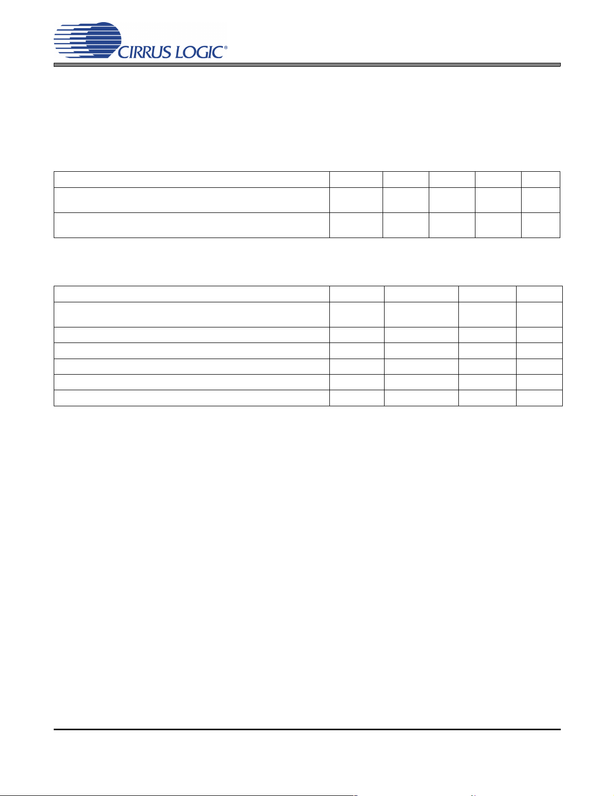
SPECIFIED OPERATING CONDITIONS
(GND = 0 V, all voltages with respect to 0 V.)
Parameter Symbol Min Typ Max Unit
DC Power Supplies: Positive Analog
Positive DigitalVAVDP
Ambient Operating Temperature Commercial (-CZZ)
Automotive (-DZZ)
T
AC
T
AA
4.75
3.1
-10
-40
5.0
3.3
5.25
5.25
-
-
+70
+85
V
V
°C
°C
ABSOLUTE MAXIMUM RATINGS
(GND = 0 V, All voltages with respect to ground.) (Note 1)
Parameter Symbol Min Max Units
DC Power Supplies: Analog
DigitalVAVDP
Input Current (Note 2) I
Analog Input Voltage (Note 3) V
Digital Input Voltage (Note 3) V
Ambient Operating Temperature (Power Applied) T
Storage Temperature T
in
IN
IND
A
stg
-0.3
-0.3
- ±10 mA
GND - 0.7 VA + 0.7 V
-0.7 VDP + 0.7 V
-50 +95 °C
-65 +150 °C
+6.0
+6.0
V
V
Notes:
1. Operation beyond these limits may result in permanent damage to the device.
Normal operation is not guaranteed at these extremes.
2. Any pin except supplies. Transient currents of up to ±100 mA on the analog input pins will not cause
SCR latch-up.
3. The maximum over/under voltage is limited by the input current.
DS650F1 3
Page 4
CS4461
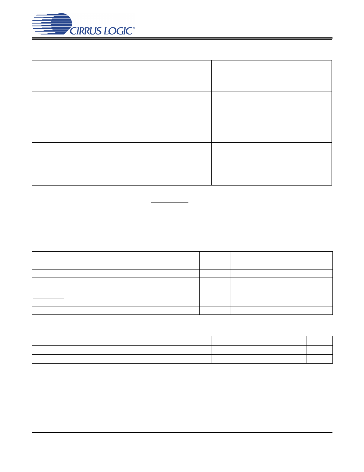
DC ELECTRICAL CHARACTERISTICS
(GND = 0 V, all voltages with respect to ground. PSR_MCLK=12.288 MHz)
Parameter Symbol Min Typ Max Unit
Power Supply Current VA
(Normal Operation) VDP = 5.0 V
VDP = 3.3 V
Power Supply Current VA
(Power-Down Mode) (Note 4) VDP = 5.0 V
Power Consumption
(Normal Operation) VDP = 5.0 V
VDP = 3.3 V
(Power-Down Mode) VDP = 5.0 V
ADC Power Supply Rejection Ratio (1 kHz) (Note 5) PSRR - 65 - dB
VQ Nominal Voltage
Output Impedance
Maximum allowable DC current source/sink
FILT+ Nominal Voltage
Output Impedance
Maximum allowable DC current source/sink
Notes:
I
A
I
D
I
D
I
A
I
D
-
-
-
-
-
-
-
-
-
-
-
-
-
-
17.5
22
14.5
2
2
198
135
20
2.5
25
0.01
5
18
0.01
21
26
17
-
-
235
161
-
-
-
-
-
-
-
mW
mW
mW
mW
mA
mA
mA
mA
mA
V
kΩ
mA
V
kΩ
mA
4. Power Down Mode is defined as PSR_RESET
= Low with all clocks and data lines held static.
5. Valid with the recommended capacitor values on FILT+ and VQ as shown in the Typical Connection
Diagram.
DIGITAL CHARACTERISTICS
Parameter Symbol Min Typ Max Units
High-Level Input Voltage (% of VDP) V
Low-Level Input Voltage (% of VDP) V
High-Level Output Voltage at I
Low-Level Output Voltage at Io = 100 µA (% of VDP) V
OVERFLOW
Input Leakage Current I
Current Sink I
= 100 µA (% of VDP) V
o
OVERFLOW
IH
IL
OH
OL
in
70% - - V
--30%V
70% - - V
--15%V
--4.0mA
--±10 µA
THERMAL CHARACTERISTICS
Parameter Symbol Min Typ Max Unit
Allowable Junction Temperature - - 135
Junction to Ambient Thermal Impedance θ
JA
-70 -
°C
°C/W
4 DS650F1
Page 5
CS4461
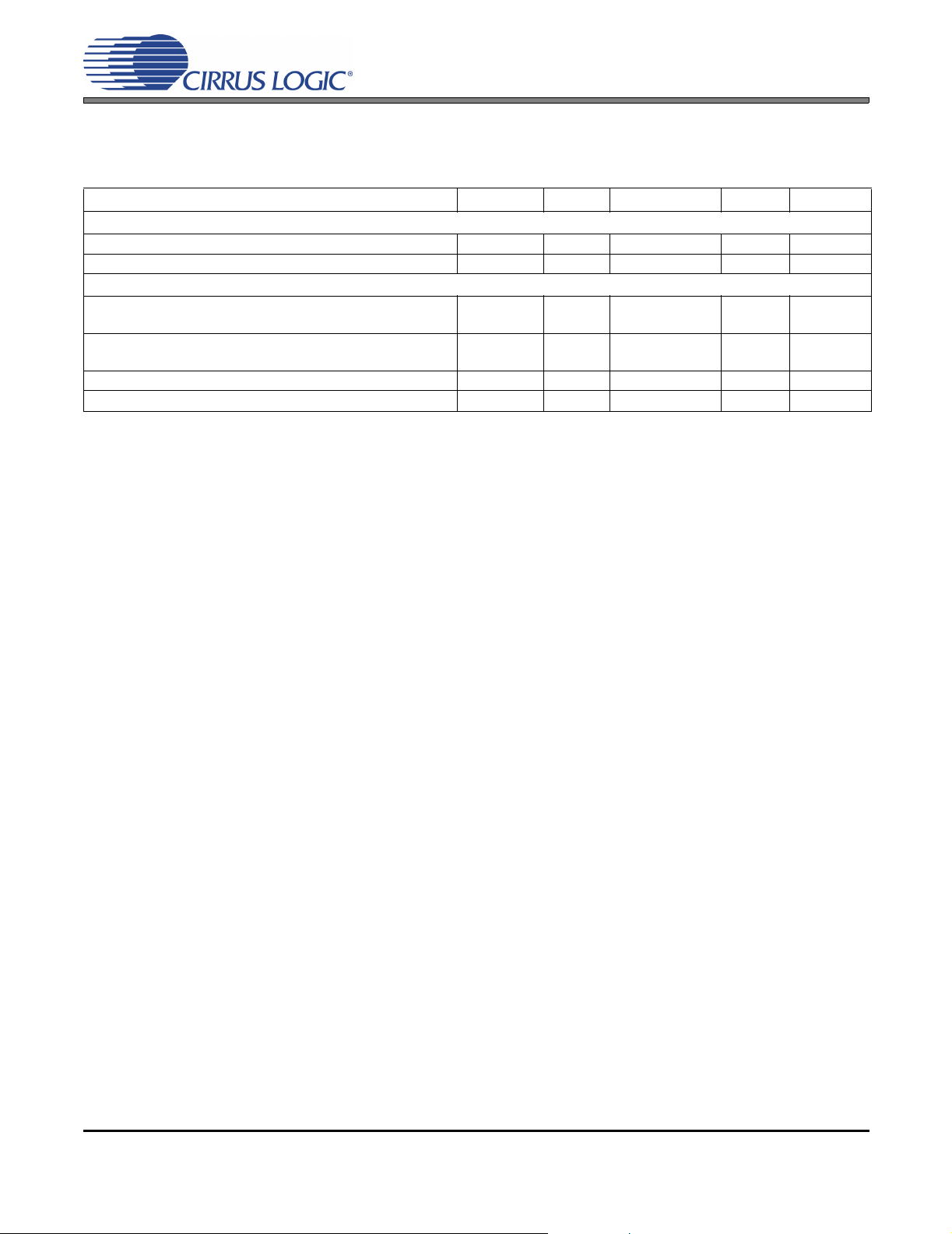
ANALOG CHARACTERISTICS
(Test conditions (unless otherwise specified): Input test signal is a 1 kHz sine wave; measurement bandwidth is
10 Hz to 20 kHz.)
Parameter Symbol Min Typ Max Unit
DC Accuracy
Gain Error - ±5%
Gain Drift -
Analog Input Characteristics
Full-scale Differential Input Voltage -CZZ
-DZZ
AIN+/AIN- Input Range -CZZ
(VA = 5.0 V) -DZZ
Input Impedance (Differential) (Note 6) 18 - - k
Common Mode Rejection Ratio CMRR - 82 - dB
-
-
1.1
1.1
Notes:
6. Measured between AIN+ and AIN-
±100 - ppm/°C
1.13*VA
1.13*VA
-
-
-
-
3.9
3.9
VPP
VPP
V
V
Ω
DS650F1 5
Page 6

2. PIN DESCRIPTIONS
CS4461
PSR_RESET FILT+
GND REFGND
PSR_SYNC VQ
PSR_DATA GND
PSR_MCLK GND
VDP VA
GND GND
VDP AIN-
TEST AIN+
GND OVERFLOW
PSR_EN VDP
GND VDP
1
2
3
4
5
6
7
24
23
22
21
20
19
18
817
9
10
11
Top-Down View
24-pin TSSOP Package
16
15
14
12 13
Pin Name # Pin Descriprion
6
8
VDP
VA 19 Analog Power (Input) - Analog power supply. Nominally +5.0 V.
GND
PSR_RESET
VQ 22 Quiescent Voltage (Output) - Filter connection for the internal quiescent reference voltage.
REFGND 23 Reference Ground (Input) - Ground reference for the internal sampling circuits.
FILT+ 24 Positive Voltage Reference (Output) - Positive reference voltage for the internal sampling circuit.
AIN+
AIN-
PSR_MCLK 5 Master Clock (Input) - Clock source for the delta-sigma modulator and output data.
PSR_SYNC 3 Synchronization Data Output (Output) - Used to synchronize the serial data in the PWM modulator.
PSR_DATA 4 PSR Serial Data Output (Output) - Power supply modulated and formatted serial data.
PSR_EN 11 PSR Enable (Input) - A high to low transition on this pin will enable the PSR feedback circuit.
OVERFLOW
TEST 9
Digital Logic Power (Input) – Digital core and input/output power supply. Nominally +3.3 V or +5.0 V.
13
Supply decoupling should placed as close as possible to pin 6.
14
2
7
10
12
Ground (Input) - Ground reference for both analog and digital.
18
20
21
Reset (Input) - When PSR_RESET
1
are reset. On initial power up, PSR_RESET
input clocks are stable in frequency and phase.
1617Differential PSR Analog Input (Input) - Signals are presented differentially to the delta-sigma modula-
tor via the AIN+/- pins.
15 Overflow (Output, open drain) - Indicates a modulator overflow condition.
Test (Output) - This pin may toggle during normal operation and should be pulled low through a 47 kΩ
resistor to GND in order to minimize noise.
is low, the CS4461 enters a low power mode and all internal states
must be held low until the power supply is stable, and all
6 DS650F1
Page 7

3. TYPICAL CONNECTION DIAGRAM
VDP VDP VDP VDP
+5.0 V
VA
47 µF
See “CS4461 Recommended Analog Input
Buffer” on page 8.
0.1 µF
AIN+
AIN-
PSR_RESET
CS4461
PSR_MCLK
PSR_SYNC
PSR_DATA
PSR_EN
+3.3 V or +5.0 V
0.1 µF
22.1 Ω
22.1 Ω
22.1 Ω
VDP
47 kΩ
CS4461
PWM
Modulator
with PSR
Processing
OVERFLOW
TEST
VQ
47 kΩ
0.1 µF1 µF
FILT+
0.1 µF47 µF
REFGND
Figure 1. Typical Connection Diagram
GND
GND
GND
GND
GND
GND
GND
DS650F1 7
Page 8

4. APPLICATIONS
4.1 Digital Connections
PSR_MCLK provides the system clock for the CS4461. PSR_SYNC and PSR_DATA provide the output of
the modulator to the class-D modulator with feedback capabilities. Series damping resistors should be used
on PSR_MCLK, PSR_SYNC, and PSR_DATA to minimize noise. These should be placed as close as possible to their signal source. The pin labeled TEST should also be pulled low to GND through a 47 kΩ resistor
to minimize noise coupling into the ADC modulator.
4.2 Analog Connections
The analog modulator samples the input at PSR_MCLK/4 (6.144 MHz with PSR_MCLK=24.576 MHz).
Figure 2 shows the suggested analog input filter. This filter topology will correctly buffer the power supply’s
AC and DC components for PSR processing by the class-D modulator. The use of capacitors which have a
large voltage coefficient (such as general purpose ceramics) must be avoided since these can degrade signal linearity. C0G dielectrics should be used wherever possible. R1 and R2 should be used to scale VP
(class-D amplifier high voltage power supply) to less than the CS4461 maximum AIN+/AIN- input voltage
(3.9 V).
CS4461
2 kΩ2 kΩ
VP
R1
R2
+5.0 V
+
-
120 pF
649 Ω
649 Ω90.9 Ω
Figure 2. CS4461 Recommended Analog Input Buffer
The following equation can be used to scale R1 and R2:
2 * (VP * (1 + %
VP_Ripple
Example (VP = 40 V, %
)) * (R2 / (R1 + R2)) < 3.9 V
VP_Ripple
= 4%):
+5.0 V
-
+
120 pF
90.9 Ω
2200 pF
C0G
AIN+
CS4461
AIN-
2 * (40 * (1 + 0.04)) * (1.96 kΩ / (40.2 kΩ + 1.96 kΩ) = 3.87 V
8 DS650F1
Page 9

4.3 Power-Up Sequence
Reliable power-up can be accomplished by keeping the device in reset until the power supplies and clocks
are stable. It is also recommended that reset be enabled if the analog or digital supplies drop below the minimum specified operating voltages to prevent power glitch related issues.
The internal reference voltage must be stable for the device to produce valid data. Therefore, there is a delay between the release of reset and the generation of valid output, due to the finite output impedance of
FILT+ and the presence of the external capacitance.
4.4 Overflow Detection
The CS4461 includes modulator overflow detection, indicated on pin 15, OVERFLOW (open drain, active
low). OVERFLOW
main low until the condition is cleared.
will go to a logical low as soon as an overrange condition is detected. The data will re-
4.5 Grounding and Power Supply Decoupling
As with any high resolution converter, the CS4461 requires careful attention to power supply and grounding
arrangements if its potential performance is to be realized. Figure 1 shows the recommended power arrangements, with VA and VDP connected to clean supplies. VDP, which powers the digital logic, may be
run from the system logic supply or may be powered from the analog supply via a resistor. In this case, no
additional devices should be powered from VDP. Decoupling capacitors should be as near to the ADC as
possible, with the low value ceramic capacitor being the nearest. All signals, especially clocks, should be
kept away from the FILT+ and VQ pins in order to avoid unwanted coupling into the modulator. The FILT+
and VQ decoupling capacitors, particularly the 0.1 µF, must be positioned to minimize the electrical path
from FILT+ to GND. The CDB44800 evaluation board demonstrates the optimum layout and power supply
arrangements. To minimize digital noise, connect the ADC digital outputs only to CMOS inputs.
CS4461
DS650F1 9
Page 10

5. PACKAGE DIMENSIONS 24L TSSOP (4.4 mm BODY) PACKAGE DRAWING
N
CS4461
1
23
TOP VIEW
D
E
e
2
b
SIDE VIEW
A2
A1
A
SEATING
PLANE
L
INCHES MILLIMETERS
1
E1
END VIEW
NOTE
DIM MIN NOM MAX MIN NOM MAX
A -- -- 0.043 -- -- 1.10
A1 0.002 0.004 0.006 0.05 -- 0.15
A2 0.03346 0.0354 0.037 0.85 0.90 0.95
b 0.00748 0.0096 0.012 0.19 0.245 0.30 2,3
D 0.303 0.307 0.311 7.70 7.80 7.90 1
E 0.248 0.2519 0.256 6.30 6.40 6.50
E1 0.169 0.1732 0.177 4.30 4.40 4.50 1
e -- 0.026 BSC -- -- 0.65 BSC --
L 0.020 0.024 0.028 0.50 0.60 0.70
µ
0° 4° 8° 0° 4° 8°
∝
JEDEC #: MO-153
Controlling Dimension is Millimeters.
Notes:
1. “D” and “E1” are reference datums and do not included mold flash or protrusions, but do include mold
mismatch and are measured at the parting line, mold flash or protrusions shall not exceed 0.20 mm per
side.
2. Dimension “b” does not include dambar protrusion/intrusion. Allowable dambar protrusion shall be
0.13 mm total in excess of “b” dimension at maximum material condition. Dambar intrusion shall not reduce dimension “b” by more than 0.07 mm at least material condition.
3. These dimensions apply to the flat section of the lead between 0.10 and 0.25 mm from lead tips.
10 DS650F1
Page 11

CS4461
6. ORDERING INFORMATION
Product Description Package Pb-Free Grade Temp Range Container Order #
Rail CS4461-CZZ
Tape & Reel CS4461-CZZR
Rail CS4461-DZZ
Tape & Reel CS4461-DZZR
CS4461
CDB44800
Multi-bit A/D for
Class-D Real-time
PSR Feedback
Evaluation board for
the CS44800/600
and the CS4461
Commercial -10° to +70° C
24-TSSOP YES
Automotive -40° to +85° C
- - - - - CDB44800
7. REVISION HISTORY
Release Date Changes
A1 May 2004 1st Advance Release
F1 September 2005 Updated ordering information
Contacting Cirrus Logic Support
For all product questions and inquiries contact a Cirrus Logic Sales Representative.
To find the one nearest to you go to www.cirrus.com
IMPORTANT NOTICE
Cirrus Logic, Inc. and its subsidiaries ("Cirrus") believe that the information contained in this document is accurate and reliable. However, the information is subject
to change without notice and is provided "AS IS" without warranty of any kind (express or implied). Customers are advised to obtain the latest version of relevant
information to verify, before placing orders, that information being relied on is current and complete. All products are sold subject to the terms and conditions of sale
supplied at the time of order acknowledgment, including those pertaining to warranty, indemnification, and limitation of liability. No responsibility is assumed by Cirrus
for the use of this information, including use of this information as the basis for manufacture or sale of any items, or for infringement of patents or other rights of third
parties. This document is the property of Cirrus and by furnishing this information, Cirrus grants no license, express or impli ed under any patents, mask work rights,
copyrights, trademarks, trade secrets or other intellectual property rights. Cirrus owns the copyrights associated with the information contained herein and gives consent for copies to be made of the information only for use within your organization with respect to Cirrus integrated circuits or other products of Cirrus. This consent
does not extend to other copying such as copying for general distribution, advertising or promotional purposes, or for creating any work for resale.
CERTAIN APPLICATIONS USING SEMICONDUCTOR PRODUCTS MAY INVOLVE POTENTIAL RISKS OF DEATH, PERSONAL INJURY, OR SEVERE PROPERTY OR ENVIRONMENTAL DAMAGE (“CRITICAL APPLICATIONS”). CIRRUS PRODUCTS ARE NOT DESIGNED, AUTHORIZED OR WARRANTED FOR USE
IN AIRCRAFT SYSTEMS, MILITARY APPLICATIONS, PRODUCTS SURGICALLY IMPLANTED INTO THE BODY, AUTOMOTIVE SAFETY OR SECURITY DEVICES, LIFE SUPPORT PRODUCTS OR OTHER CRITICAL APPLICATIONS. INCLUSION OF CIRRUS PRODUCTS IN SUCH APPLICATIONS IS UNDERSTOOD TO BE FULLY AT THE CUSTOMER’S RISK AND CIRRUS DISCLAIMS AND MAKES NO WARRANTY, EXPRESS, STATUTORY OR IMPLIED,
INCLUDING THE IMPLIED WARRANTIES OF MERCHANTABILITY AND FITNESS FOR PARTICULAR PURPOSE, WITH REGARD TO ANY CIRRUS PRODUCT
THAT IS USED IN SUCH A MANNER. IF THE CUSTOMER OR CUSTOMER’S CUSTOMER USES OR PERMITS THE USE OF CIRRUS PRODUCTS IN CRITICAL
APPLICATIONS, CUSTOMER AGREES, BY SUCH USE, TO FULLY INDEMNIFY CIRRUS, ITS OFFICERS, DIRECTORS, EMPLOYEES, DISTRIBUTORS AND
OTHER AGENTS FROM ANY AND ALL LIABILITY, INCLUDING ATTORNEYS’ FEES AND COSTS, THAT MAY RESULT FROM OR ARISE IN CONNECTION
WITH THESE USES.
Cirrus Logic, Cirrus, and the Cirrus Logic logo designs are trademarks of Cirrus Logic, Inc. All other brand and product names in this document may be trademarks
or service marks of their respective owners.
DS650F1 11
 Loading...