

Page 1

K6860631 – WI-FI ROUTER
Click on the desired vehicle to take you directly to the vehicle specific
instructions.
08 RAM/09 RAM HEAVY DUTY – REGULAR CAB
08 RAM/09 RAM HEAVY DUTY – QUAD CAB
09 RAM – REGULAR CAB
09 RAM – QUAD/CREW CAB
300/CHARGER/CHALLENGER
CALIBER
COMMANDER
COMPASS
DAKOTA
DURANGO/ASPEN
GRAND CHEROKEE
JOURNEY
MINIVAN
NITRO/LIBERTY
PACIFICA
PATRIOT
PT CRUISER
SEBRING SEDAN/AVENGER
SPRINTER
WRANGLER
Aug 08, 2008 K6860631 Rev. 1
Page 2
WI-FI ROUTER
INDEX
PRINT THIS VEHICLE
DODGE RAM-REGULAR CAB
PROCEDURE STEPS:
NOTE: Using a test light, verify the cigarette lighter outlet being used is ignition switched. Power must not be
supplied with the ignition in the OFF position.
NOTE: If equipped with the mini console, proceed to step 4. If equipped with a full console, proceed to step 11.
1. Disconnect and isolate the battery negative cable.
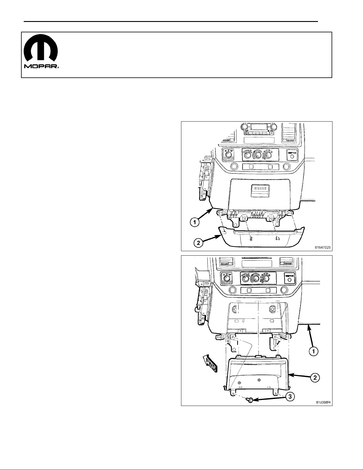
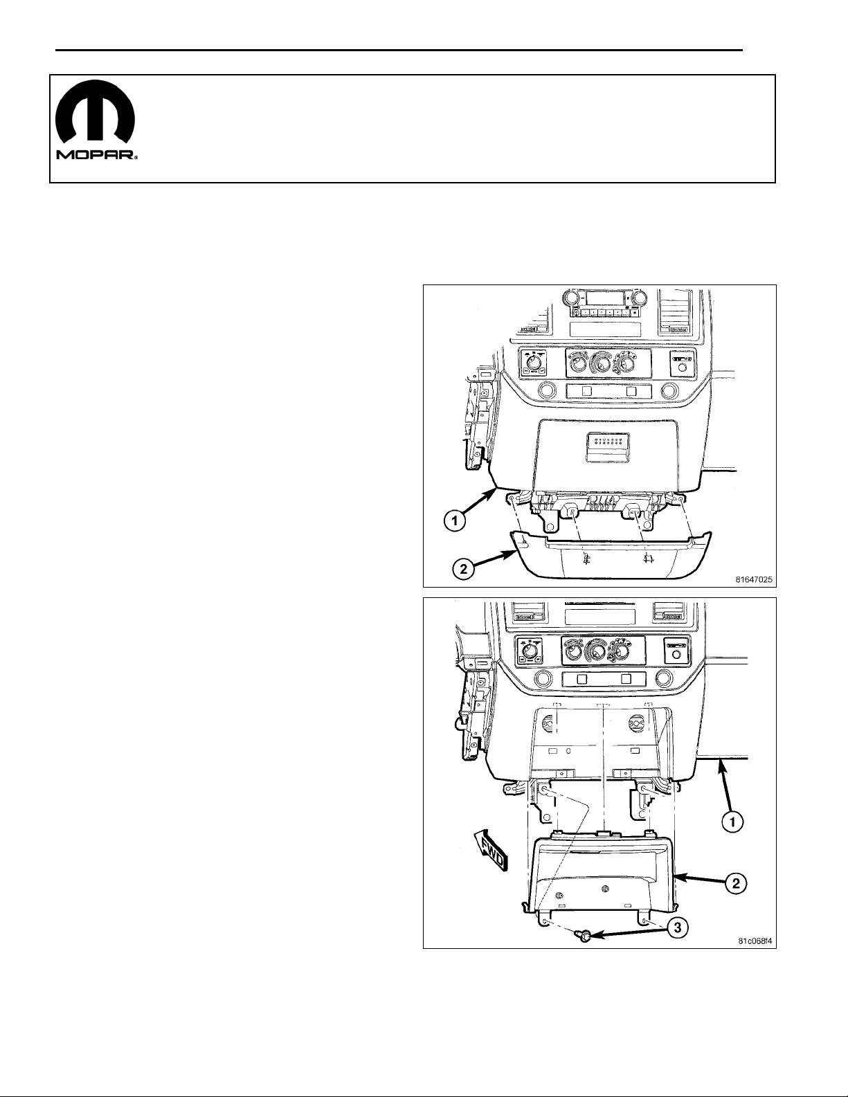
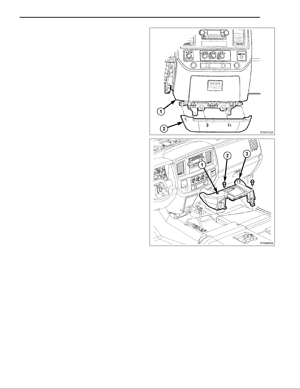
2. UsingatrimstickC-4755or equivalent,disengage the
retaining tabs and remove the lower bezel panel (2).
1
3. Remove the two lower screws (3) securing the cup
holder or close out panel (2) to the instrument panel
(IP).
Aug 08, 2008 K6860631 Rev. 1
Page 3

2
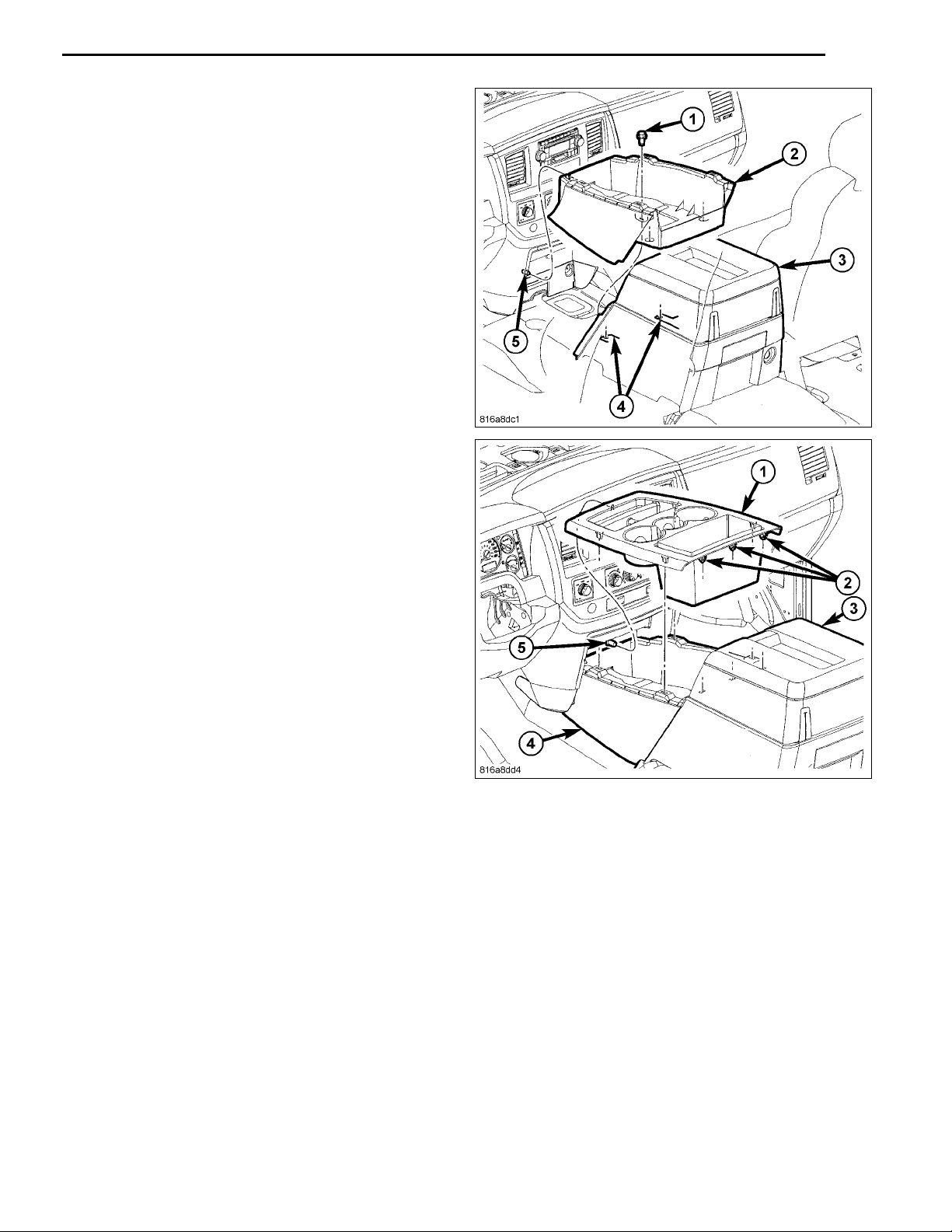
4. Onvehicles withamini console, remove the 4WD gear
shift boot, if equipped.
5. If equipped with a manual transmission, remove the
transmission gear shift lever extension.
6. Remove the console inserts, if equipped.
7. Remove the bolts (2) that secure the rear console (1)
to the floor panel.
8. Lift up the rear of the floor console to clear the gear
shift lever, if equipped.
Aug 08, 2008 K6860631 Rev. 1
Page 4
9. Remove the bolts (2) and separate the front console
(3) from the floor.
10. Separate the front clips (1) and remove the mini console.
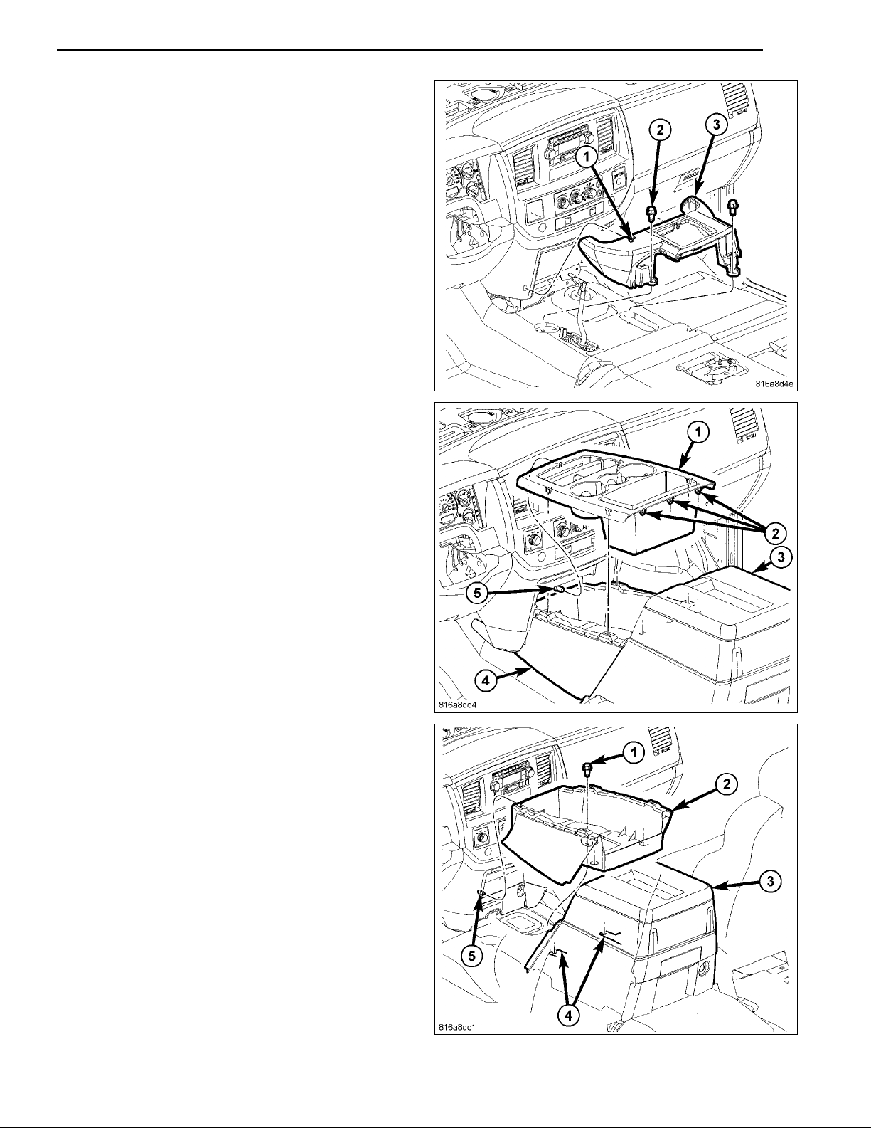
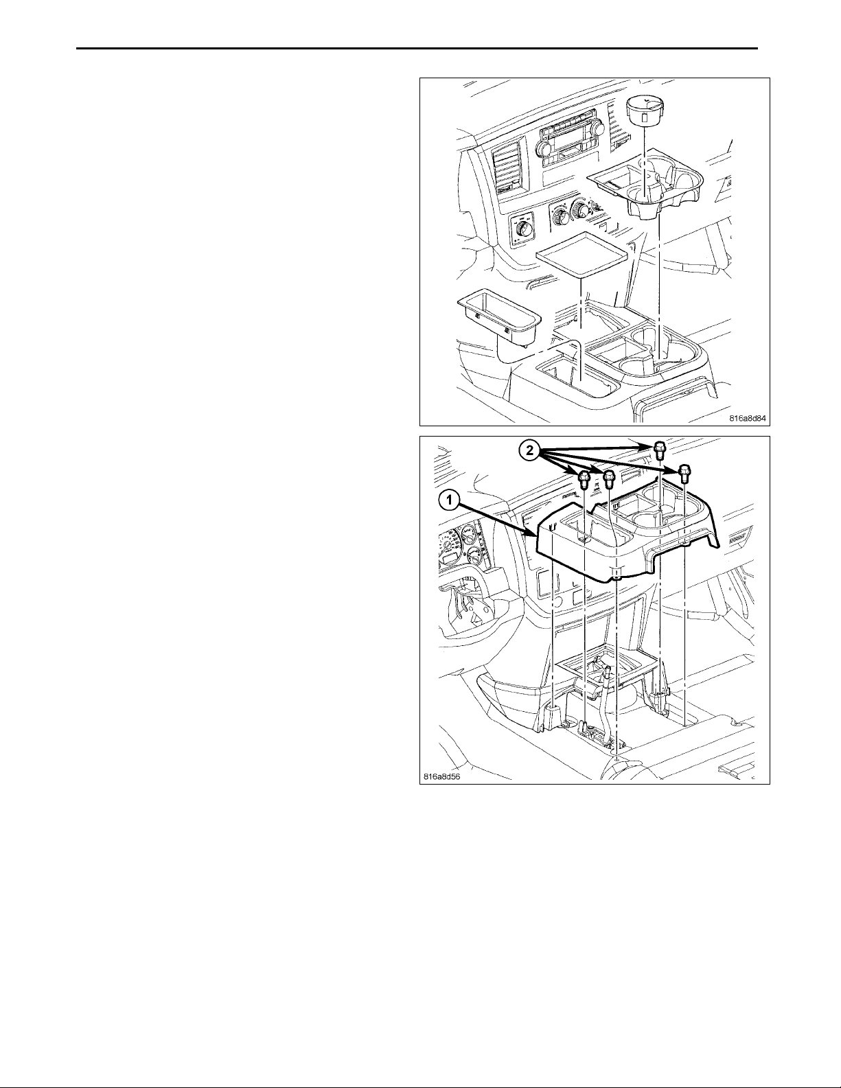
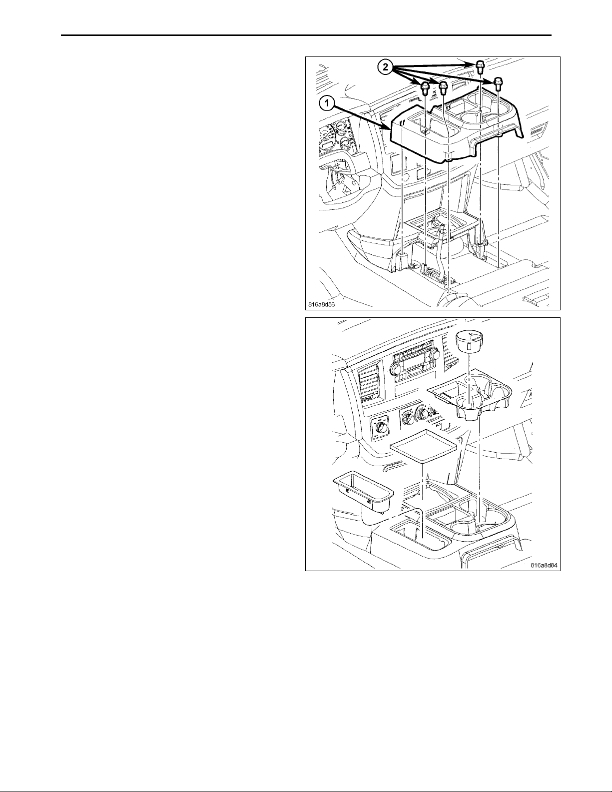
11. On vehicles with a full center console, using a trim
stick C-4755 or equivalent, separate the s even front
console bezel clips (2), lift up the back of the bezel (1)
and remove.
3
12. Remove the bolts (1) and lift the rear of the base up to
release the front guide pins (5).
13. Remove the front base (2).
Aug 08, 2008 K6860631 Rev. 1
Page 5
4
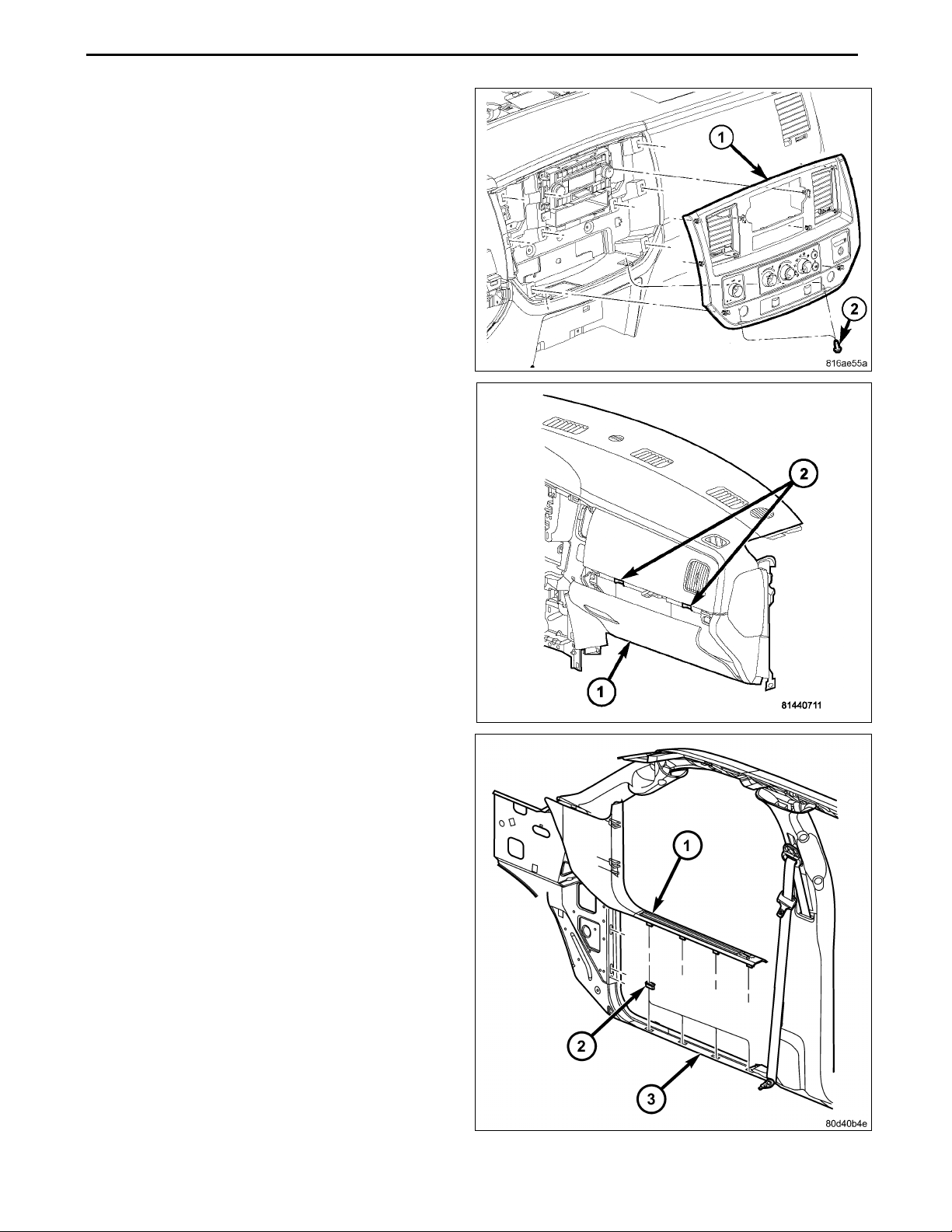
14. Remove the screws (2).
15. Using a trimstick C-4755 or equivalent, disengage the
retainer clips that secure the instrument panel center
bezel (1 ) to the instrument panel.
16. Disconnect the wire harness connectors and remove
the center bezel from the vehicle.
17. Open the glove box (1).
18. Release the two glove box stops (2) and lower the
glove box downward past the stops.
19. Disengage the glove box hinges from the instrument
panel and remove the glove box.
20. Using a trim stick C-4755 or e
retaining tabs of the cowl t
tainer clip s (2) in the door
21. Pull the cowl trim panel r
the vehicle.
sill (3).
earward and remove it from
quivalent,disengage the
rim panel (1) from the re-
Aug 08, 2008 K6860631 Rev. 1
Page 6
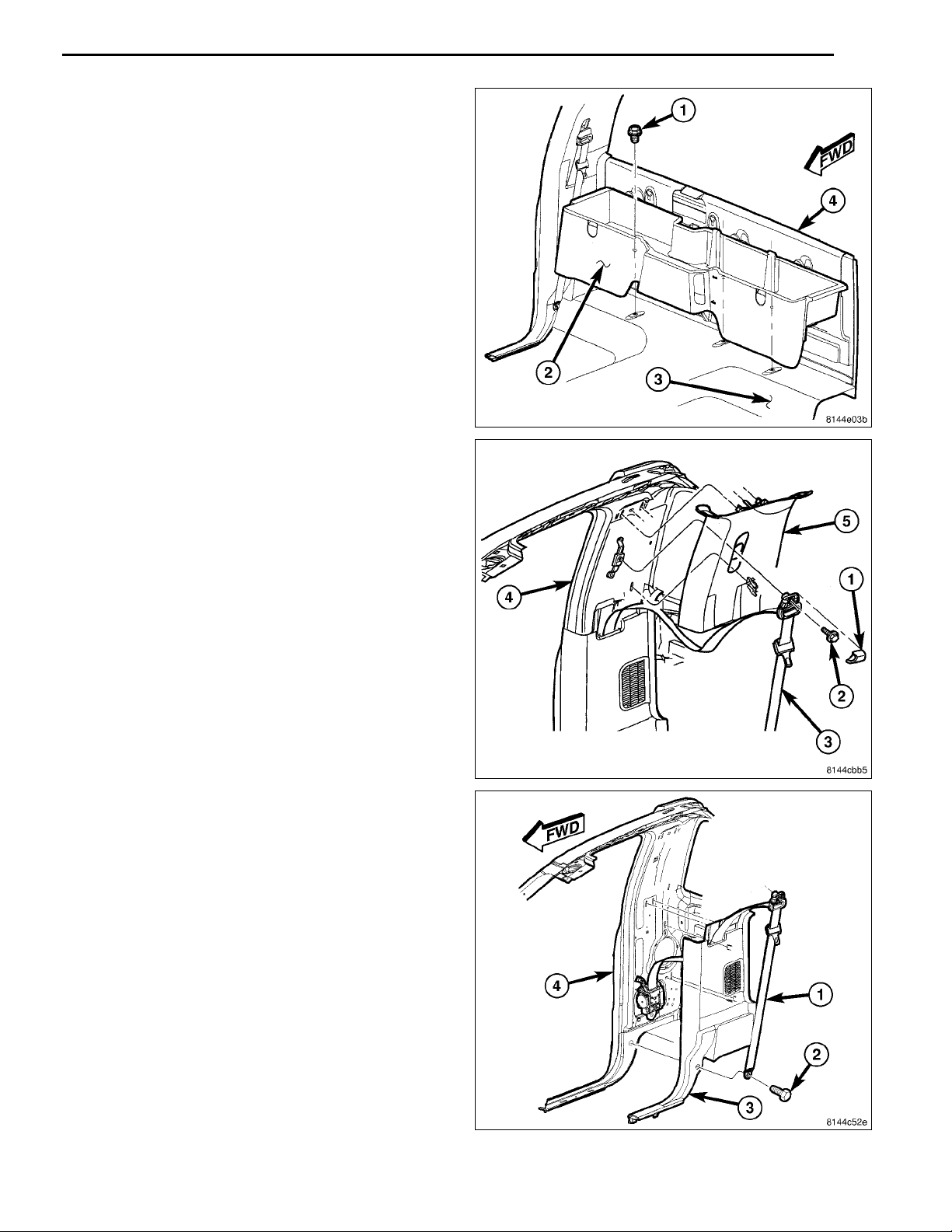
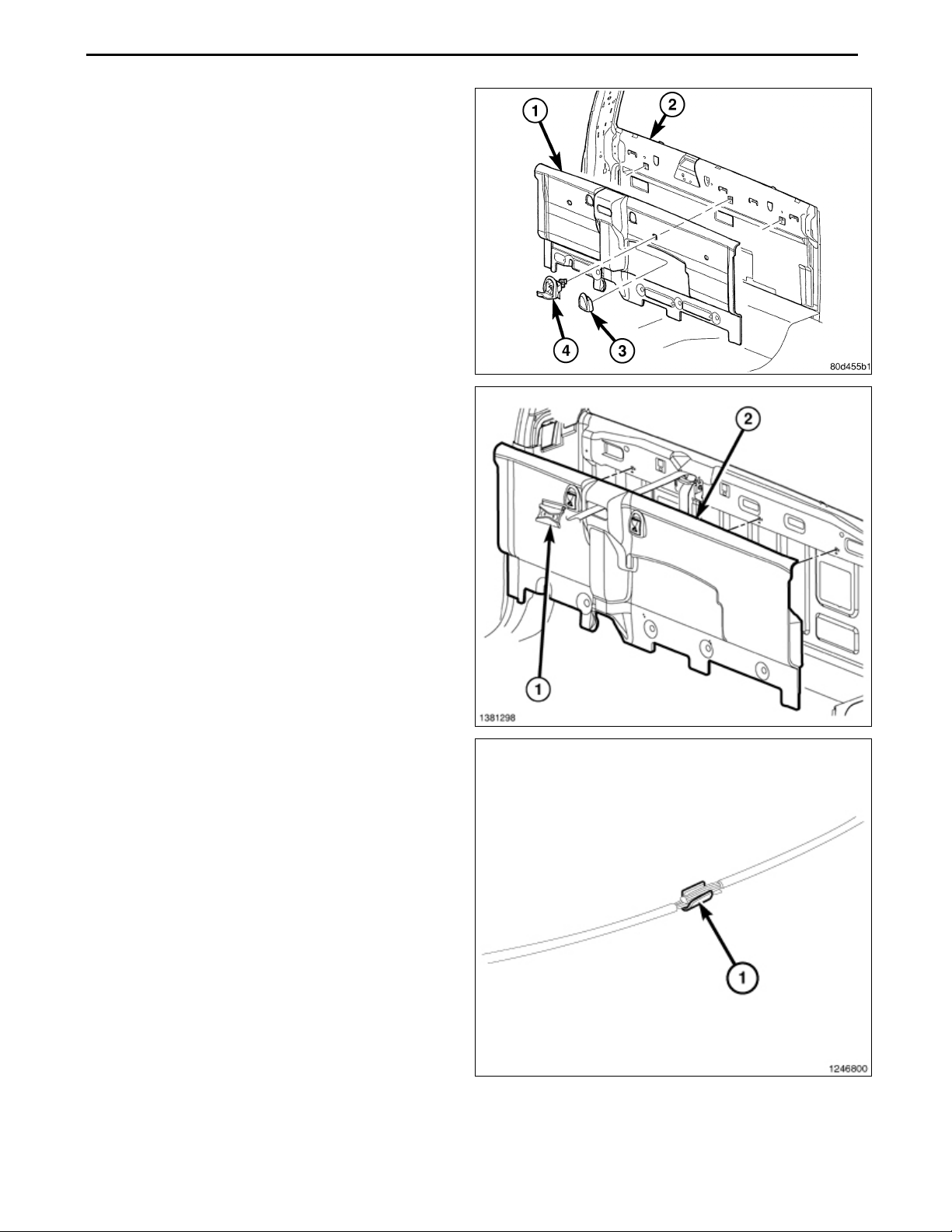
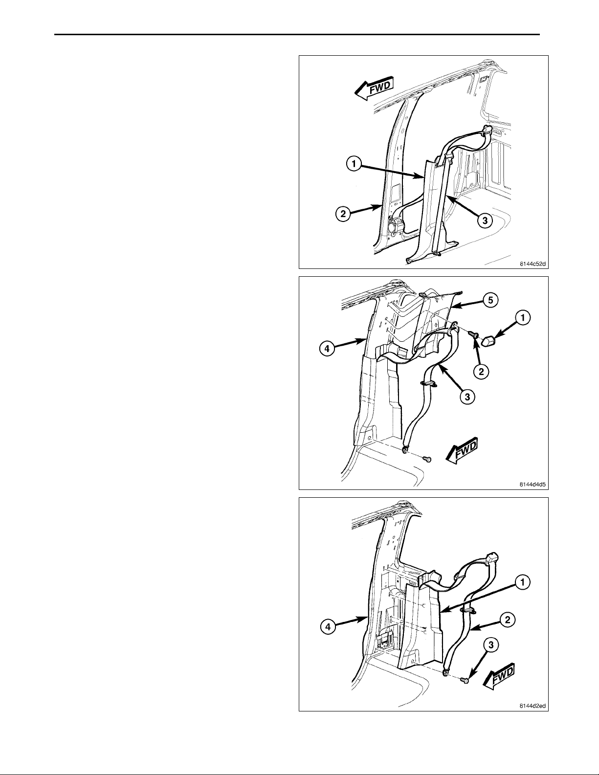
22. Remove the three bolts (1) that secure the rear storagecompartment (2) to the floor panel (3) and remove
the storage compartment from the rear cab trim panel
(4).
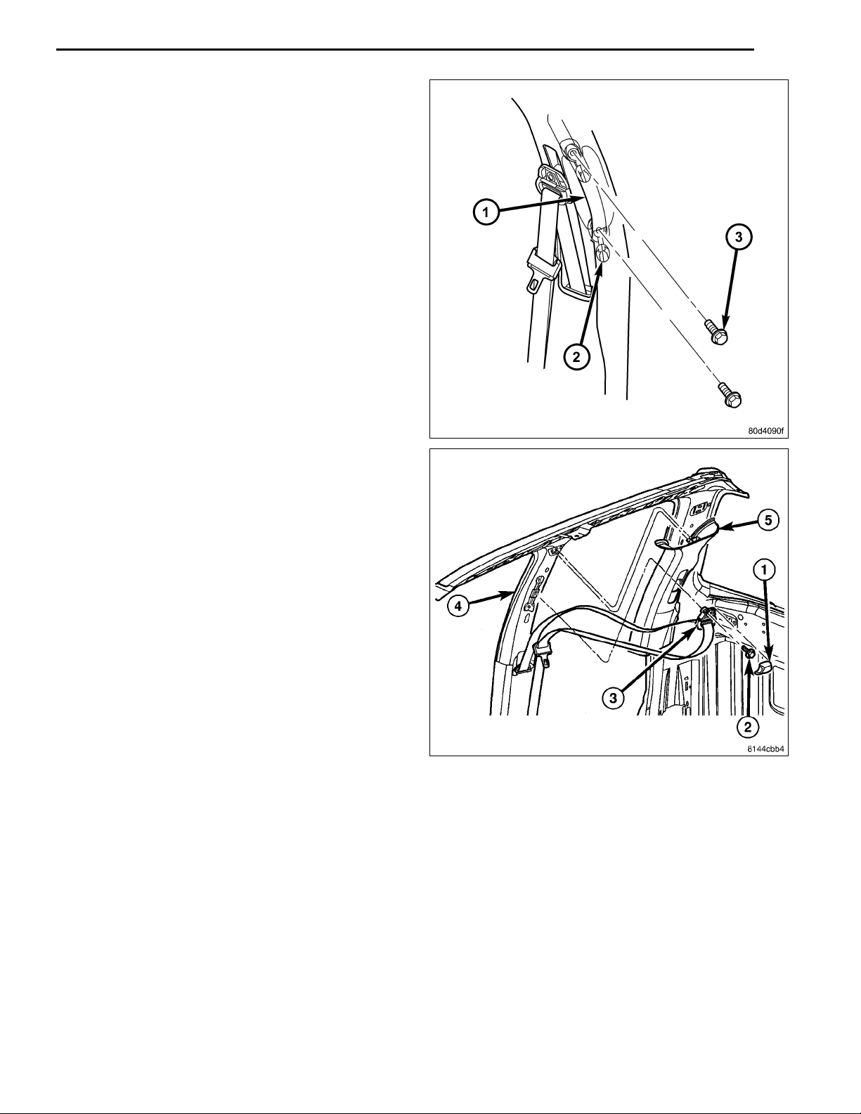
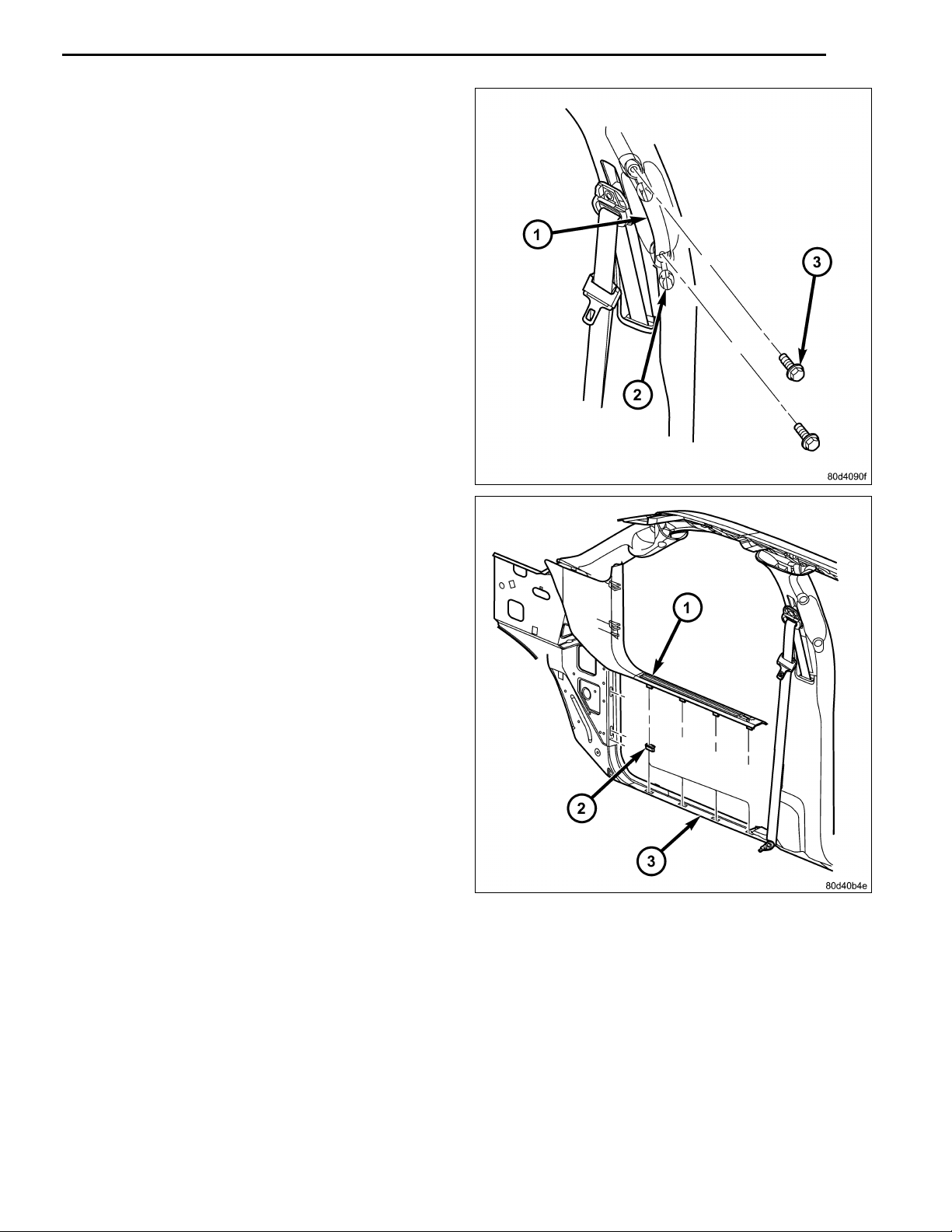
23. Remove the cap (1) and then the bolt (2) that secures
the seat belt (3) to the top of the B-pillar (4) and position the seat belt out of the way.
24. Using a trimstick C-4755 or equivalent, disengage the
retaining tabs that secure the upper B-pillar trim panel
(5) to the B-pillar and rem ove the trim panel.
5
25. Remove the bolt (2) that secures the seat belt (1) to
the bottom of the B-pillar (4) and position the seat belt
outoftheway.
26. Using a trimstick C-4755 or equivalent, disengage the
retaining tabs that secure the lo wer B-pillar trim panel
(3) to the B-pillar.
27. Remove the seat belt from the lower B-pillar trim panel
through the slot provided and remove the trim panel.
Aug 08, 2008 K6860631 Rev. 1
Page 7
6
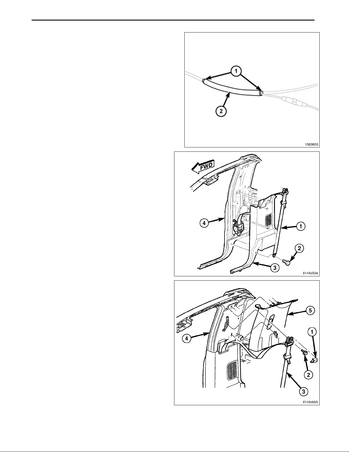
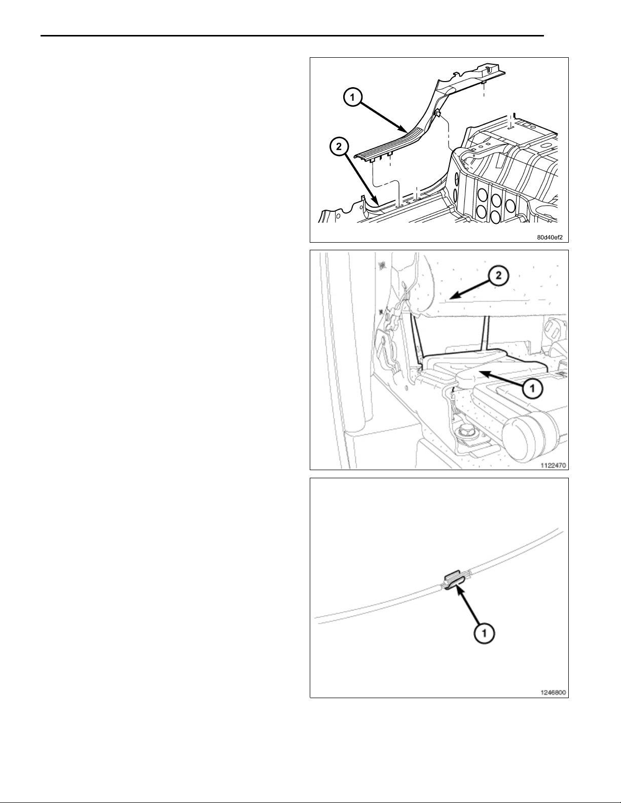
28. Remove the utility hoo ks (3) from the rear cab trim
panel (1) and remove the trim panel.
29. Install the Wi-Fi router to the rear cab trim panel with
the provided materials.
30. Make a small cut in the rear cab trim panel and route
the Wi-Fi router connector through
31. Place the rear cab trim panel into position in the
cle.
32. Connect the wire harness to the Wi-Fi router conn
tor.
33. Route the wire harness down the back of the re
panel to the door sill.
34. Firmly seat the rear panel and install the ut
to the rear panel.
35. Continue to route the wire harness along the
ger side, under the glove box opening and be
center stack.
vehi-
ec-
ar
ility hooks
passenhind the
36. Locate the cigarette lighter outlet wiring harness.
37. Cut each wire and remove 13 mm (0.5 in.) of insulation from each wire that needs to be soldered/spliced.
38. Place a piece of supplied adhesive lined heat shrink
tubing on one side of each cut wire. Insure the tubing
will be long enough to cover and seal the entire soldered area.
CAUTION: Do not use acid core solder.
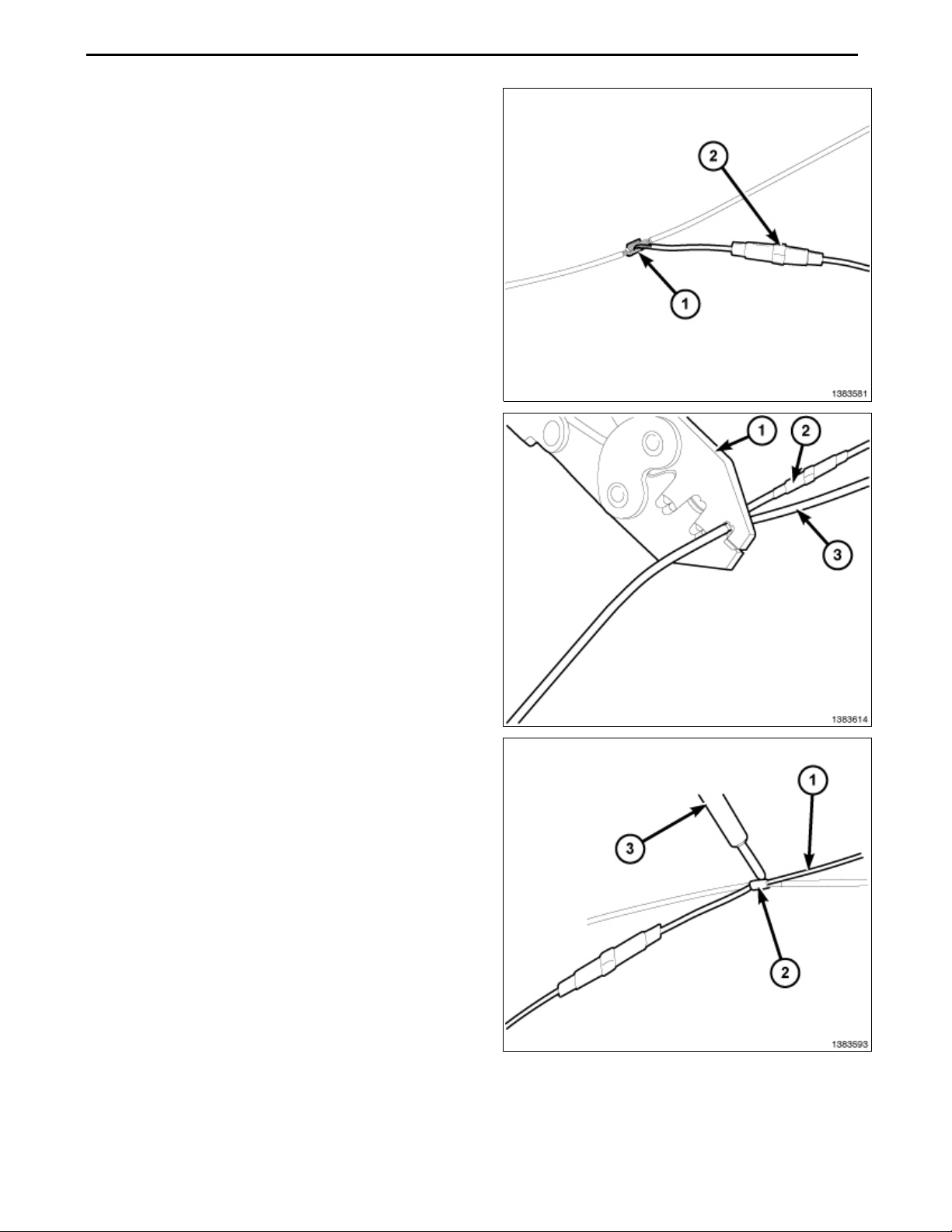
39. Solder the supplied fused pigtail to Wi-Fi power harness power wire.
Aug 08, 2008 K6860631 Rev. 1
Page 8

40. Place the strandsofthepowersidewires overlappingeach
other inside of the splice clip (1).
41. Using crimpingtool(1),Mopar® p/n 05019912AA or equivalent, crimp the splice clip and wires together.
42. Repeat the previous two steps for the ground side wires.
7
CAUTION: Do not use acid core solder.
43. Solder (3) the connection (2) together using rosin core solder (1).
Aug 08, 2008 K6860631 Rev. 1
Page 9
8
44. Center the heat shrink tubing (2) over the solder joint and
heat using a heat gun. Heat the joint until the tubing is
tightly sealed and sealant (1) comes out of both ends of
the tubing.
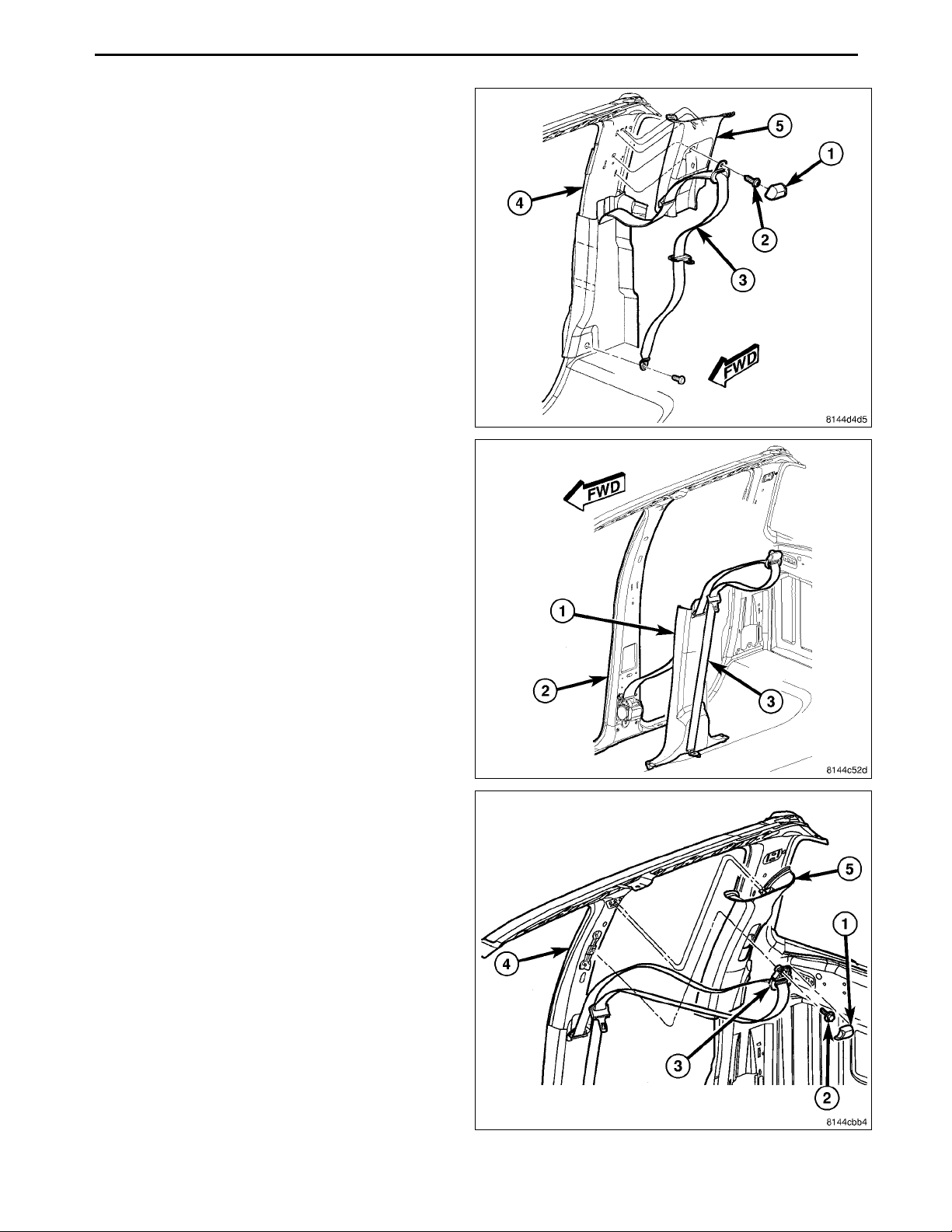
45. Place the lo w er B-pillar trim panel (3) into position and
engage the retaining tabs that secure the trim panel to
the B-pillar (4).
46. Route the seat belt through the slot provided in the
B-pillar trim panel.
47. Install the bolt (2) that secures the seat belt (1) to the
bottom of the B-pillar (4).
48. Place the upper B-pillar trim panel (5) into position and
engage the retaining tabs that secure the trim panel to
the B-pillar (4).
49. Install the bolt (2) that secures the seat belt (3) to the
top of the B-pillar (4) and Install the cap (1).
Aug 08, 2008 K6860631 Rev. 1
Page 10
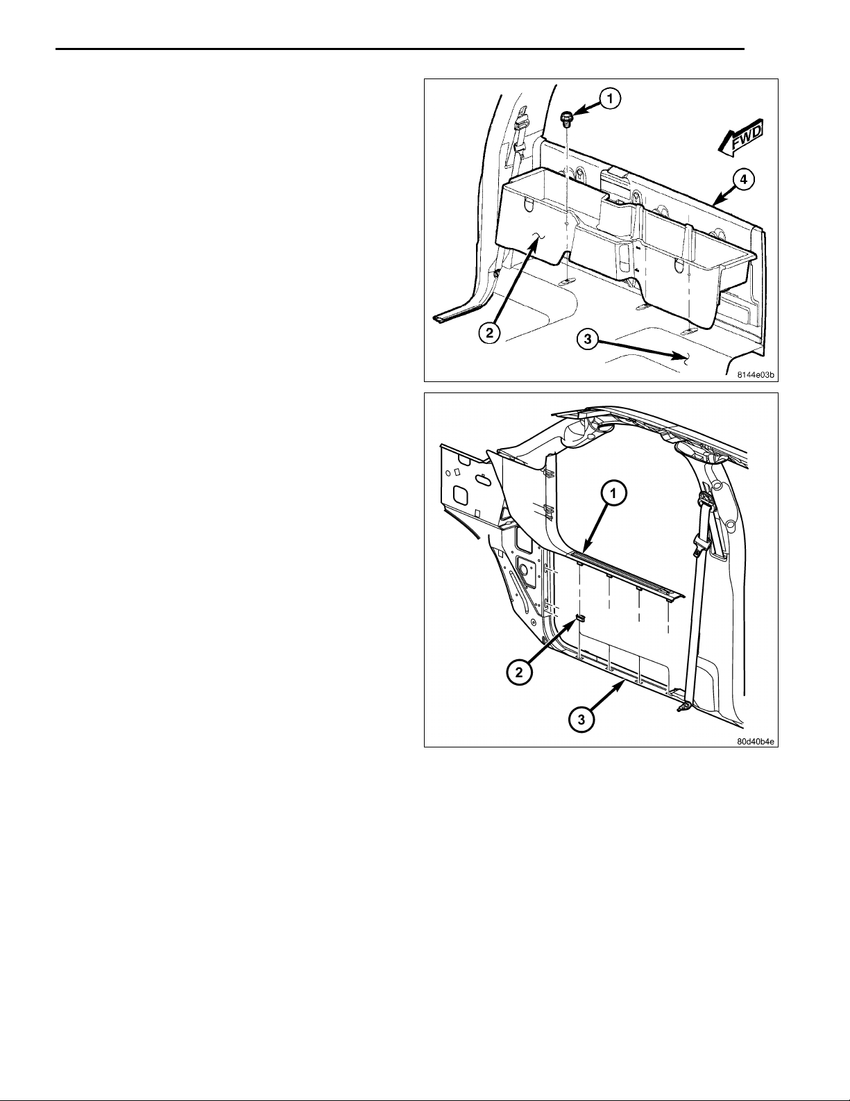
50. Install thestorage compartment (2)to the rearcab and
installthe three fasteners (1) that secure the rear storage compartment to the floor panel (3).
51. Place the cowl trim panel (1) into position and engage
the retaining tabs to the door sill (3).
9
Aug 08, 2008 K6860631 Rev. 1
Page 11
10
52. Engage the glove box (1) hinges to the instrument
panel.
53. Press the two glove box stops (2) and raise the glove
box upward.
54. Close the glove box.
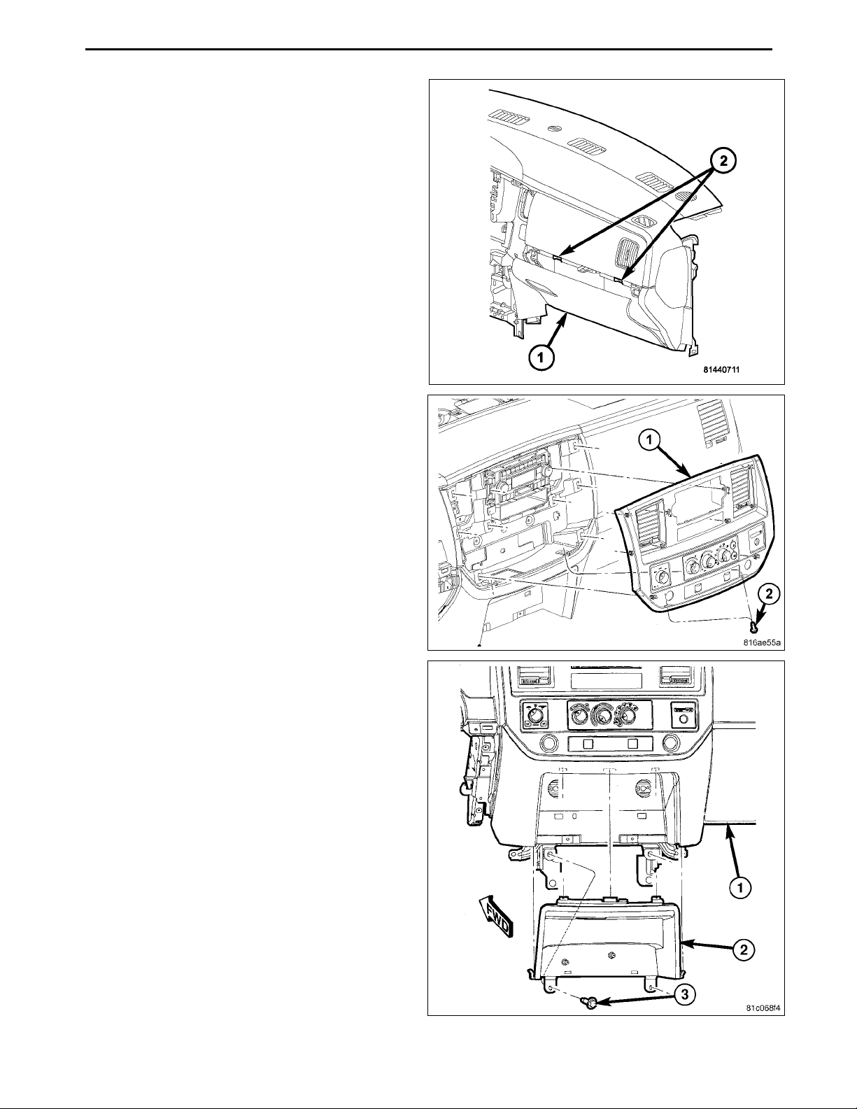
55. Position theinstrumentpanel center bezel(1) near the
IP and connect the wire harness connectors.
56. Install the instrument panel center bezel onto the IP
and fully engage the retainer clips.
57. Install the two lower screws (2).
58. If necessary, install the cl
cupholder and install the s
crews (3).
ose out panel (2) or
Aug 08, 2008 K6860631 Rev. 1
Page 12

59. Install the lower bezel panel (2) ensuring the retaining
tabs engage.
60. If equipped with a mini console, position the console
and seat the front clips (1) fully.
61. Install the bolts (2).
11
Aug 08, 2008 K6860631 Rev. 1
Page 13

12
62. Install the bolts (2) that secure the rear console (1) to
the floor panel.
63. Install the inserts.
64. Install the gear shift lever extension.
65. Install the 4WD gear shift boot, if equipped.
Aug 08, 2008 K6860631 Rev. 1
Page 14
66. If equipped with a full console, Install the front base
(2).
67. Seat the rear of the base to engage the front guide
pins (5) and Install the bolts (1).
68. Install the console bezel (1) and engage the seven
front console bezel clips (2).
69. Connect the battery negative cable.
13
Aug 08, 2008 K6860631 Rev. 1
Page 15
WI-FI ROUTER
INDEX
PRINT THIS VEHICLE
DODGE RAM-QUAD CAB
PROCEDURE STEPS:
NOTE: Using a test light, verify the cigarette lighter outlet being used is ignition switched. Power must not be
supplied with the ignition in the OFF position.
NOTE: If equipped with the mini console, proceed to step 4. If equipped with a full console, proceed to step 11.
1. Disconnect and isolate the battery negative cable.
2. Usinga trim stick C-4755or equivalent,disengage the
retaining tabs and remove the lower bezel panel (2).
1
3. Remove the two lower screws (3) securing the cup
holder or close out panel (2) to the instrument panel
(IP).
Aug 08, 2008 K6860631Rev. 1
Page 16
2
4. Onvehicles withamini console, remove the 4WD gear
shift boot, if equipped.
5. If equipped with a manual transmission, remove the
transmission gear shift lever extension.
6. Remove the console inserts, if equipped.
7. Remove the bolts (2) that secure the rear console (1)
to the floor panel.
8. Lift up the rear of the floor console to clear the gear
shift lever, if equipped.
Aug 08, 2008 K6860631Rev. 1
Page 17

9. Remove the bolts (2) and separate the front console
(3) from the floor.
10. Separate the front clips (1) and remove the mini console.
11. On vehicles with a full center console, using a trim
stick C-4755 or equivalent, separate the s even front
console bezel clips (2), lift up the back of the bezel (1)
and remove.
3
12. Remove the bolts (1) and lift the rear of the base up to
release the front guide pins (5).
13. Remove the front base (2).
Aug 08, 2008 K6860631Rev. 1
Page 18

4
14. Remove the screws (2).
15. Using a trimstick C-4755 or equivalent, disengage the
retainer clips that secure the instrument panel center
bezel (1 ) to the instrument panel.
16. Disconnect the wire harness connectors and remove
the center bezel from the vehicle.
17. Open the glove box (1).
18. Release the two glove box stops (2) and lower the
glove box downward past the stops.
19. Disengage the glove box hinges from the instrument
panel and remove the glove box.
20. Using a trim stick C-4755 or e
retaining tabs of the cowl t
tainer clip s (2) in the door
21. Pull the cowl trim panel r
the vehicle.
sill (3).
earward and remove it from
quivalent,disengage the
rim panel (1) from the re-
Aug 08, 2008 K6860631Rev. 1
Page 19
22. Using a small flat-bladed tool, carefully open the two
fastener covers (2) located on the grab handle (1).
23. Remove the two bolts (3) that secure the grab handle
to the B-pillar and remove the grab handle.
24. Remove the cap (1) and the bolt (2) that secures the
seat belt (3 ) to the top of the B-pillar (4) and position
the seat belt out of the way.
25. Using a trimstick C-4755 or equivalent, disengage the
retaining tabs that secure the upper B-pillar trim panel
(5) to the B-pillar and rem ove the trim panel.
5
Aug 08, 2008 K6860631Rev. 1
Page 20
6
26. Using a trimstick C-4755 or equivalent, disengage the
retaining tabs that secure the lo wer B-pillar trim panel
(1) to the B-pillar (2).
27. Remove the seat belt (3) from the lower B-pillar trim
panel through the slot provided and remove the trim
panel.
28. Remove the cap (1) and then the bolt (2) that secures
the seat belt (3) to the top of the C-pillar (4) and position the seat belt out of the way.
29. Using a trim stick C-4755 orequivalent, disengage the
retaining tabs that secure the upper C-pillar trim panel
(5) to the C-pillar and remove the trim panel.
30. Remove the bolt (3) that secures the seat belt (2) to
the bottom of the C-pillar (4) and position the seat belt
outoftheway.
31. Using a trim stick C-4755 orequivalent, disengage the
retaining tabs that secure the lower C-pilla r trim panel
(1) to the C-pillar.
32. Remove theseat belt from the lower C-pillar trim panel
through the slot provided and remove the trim panel.
Aug 08, 2008 K6860631Rev. 1
Page 21
33. Using a trim stick C-4755 orequivalent, disengage the
retaining tabs of the sill trim panel (1) from the re tainer
clipsin therear door sill (2) and remove the trim panel.
34. Install and secure the wi-fi router to the floor.
35. Route the wi-fi power harness from the router along
the sill securing where necessary. and cut to the
proper length.
7
36. Locate the cigarette lighter outlet wiring harness.
37. Cut each wire and remove 13 mm (0.5 in.) of insulation from each wire that needs to be soldered/spliced.
38. Place a piece of supplied adhesive lined heat shrink
tubing on one side of each cut wire. Insure the tubing
will be long enough to cover and seal the entire soldered area.
CAUTION: Do not use acid core solder.
39. Solder the supplied fused pigtail to Wi-Fi power harness power wire.
Aug 08, 2008 K6860631Rev. 1
Page 22
8
40. Place the strandsofthepowersidewires overlappingeach
other inside of the splice clip (1).
41. Using crimpingtool(1),Mopar® p/n 05019912AA or equivalent, crimp the splice clip and wires together.
42. Repeat the previous two steps for the ground side wires.
43. Solder (3) the connection (2) together using rosin core solder (1).
Aug 08, 2008 K6860631Rev. 1
Page 23

44. Center the heat shrink tubing (2) over the solder joint and
heat using a heat gun. Heat the joint until the tubing is
tightly sealed and sealant (1) comes out of both ends of
the tubing.
45. Engage the retaining tabs of the sill trim panel (1) retainer clips in the rear door sill (2) and install the sill
trim panel.
9
46. Route the seat belt (2) throug
C-pillar trim panel (1) and p
the C-pillar (4).
47. Engage the retaining tabs th
lar trim panel to the C-pill
48. Install the bolt (3) that s
tom of the C-pillar. Tight
lbs.).
osition the trim panel to
at secure the lower C-pil-
ar.
ecures the seat belt to the bot-
entheboltto40N·m(30ft.
h the slot in the lower
Aug 08, 2008 K6860631Rev. 1
Page 24
10
49. Position the upper C-pillar trim panel (5) to the C-pillar
(4).
50. Engage the retaining tabs that secure the upper C-pillar trim panel to the C-pillar.
51. Install the bolt (2) that secures the seat belt (3) to the
top of the C-pillar. Tighten the bolt to 40 N·m (30 ft.
lbs.).
52. Install the cap (1) onto the seat belt.
53. Route the seat belt (3) through the slot in the l
B-pillar trim panel (1) and position the trim
B-pillar (2).
54. Engage the retaining tabs that secure the low
lar trim panel to the B-pillar.
55. Position the upper B-pillar trim panel (5) to the B-pillar
(4).
56. Engage the retaining tabs that secure the upper B-pillar trim panel to the B-pillar.
57. Install the bolt (2) that secures the seat belt (3) to the
top of the B-pillar. Tighten the bolt to 40 N·m (30 ft.
lbs.).
58. Install the cap (1) onto the seat belt.
ower
panel to the
er B-pil-
Aug 08, 2008 K6860631Rev. 1
Page 25
59. Install the grab handle (1) onto the B-pillar and install
thetwobolts(3). Tightentheboltsto6N·m(55in.
lbs.).
60. Close the two fastener covers (2) located on the grab
handle.
61. Position the cowl trim panel (1) onto the door sill (3).
62. Push the cowl trim panel forward and then engage the
retaining tabs that secure the sill trim panel to the rear
door sill.
11
Aug 08, 2008 K6860631Rev. 1
Page 26

12
63. Engage the glove box (1) hinges to the instrument
panel.
64. Press the two glove box stops (2) and raise the glove
box upward.
65. Close the glove box.
66. Position theinstrumentpanel center bezel(1) near the
IP and connect the wire harness connectors.
67. Install the instrument panel center bezel onto the IP
and fully engage the retainer clips.
68. Install the two lower screws (2).
69. If necessary, install the cl
cupholder and install the s
crews (3).
ose out panel (2) or
Aug 08, 2008 K6860631Rev. 1
Page 27
70. Install the lower bezel panel (2) ensuring the retaining
tabs engage.
71. If equipped with a mini console, position the console
and seat the front clips (1) fully.
72. Install the bolts (2).
13
Aug 08, 2008 K6860631Rev. 1
Page 28
14
73. Install the bolts (2) that secure the rear console (1) to
the floor panel.
74. Install the inserts.
75. Install the gear shift lever extension.
76. Install the 4WD gear shift boot, if equipped.
Aug 08, 2008 K6860631Rev. 1
Page 29

77. If equipped with a full console, Install the front base
(2).
78. Seat the rear of the base to engage the front guide
pins (5) and Install the bolts (1).
79. Install the console bezel (1) and engage the seven
front console bezel clips (2).
80. Connect the battery negative cable.
15
Aug 08, 2008 K6860631Rev. 1
Page 30

WI-FI ROUTER
INDEX
PRINT THIS VEHICLE
DODGE R AM-REGULAR CAB
PROCEDURE STEPS:
NOTE: Using a test light, verify the cigarette lighter outlet being used is ignition switched. Power must not be
supplied with the ignition in the OFF position.
NOTE: If equipped with the mini console, proceed to step 4. If equipped with a full console, proceed to step 11.
1. Disconnect and isolate the battery negative cable.
2. Usinga trim stick C-4755or equivalent,disengage the
retaining tabs and remove the lower bezel panel (2).
1
3. Remove the two lower screws (3) securing the cup
holder or close out panel (2) to the instrument panel
(IP).
Aug 08, 2008 K6860631 Rev. 1
Page 31

2
4. Onvehicles withamini console, remove the 4WD gear
shift boot, if equipped.
5. If equipped with a manual transmission, remove the
transmission gear shift lever extension.
6. Remove the console inserts, if equipped.
7. Remove the bolts (2) that secure the rear console (1)
to the floor panel.
8. Lift up the rear of the floor console to clear the gear
shift lever, if equipped.
Aug 08, 2008 K6860631 Rev. 1
Page 32

9. Remove the bolts (2) and separate the front console
(3) from the floor.
10. Separate the front clips (1) and remove the mini console.
11. On vehicles with a full center console, using a trim
stick C-4755 or equivalent, separate the s even front
console bezel clips (2), lift up the back of the bezel (1)
and remove.
3
12. Remove the bolts (1) and lift the rear of the base up to
release the front guide pins (5).
13. Remove the front base (2).
Aug 08, 2008 K6860631 Rev. 1
Page 33

4
14. Remove the screws (2).
15. Using a trimstick C-4755 or equivalent, disengage the
retainer clips that secure the instrument panel center
bezel (1 ) to the instrument panel.
16. Disconnect the wire harness connectors and remove
the center bezel from the vehicle.
17. Open the glove box (1).
18. Release the two glove box stops (2) and lower the
glove box downward past the stops.
19. Disengage the glove box hinges from the instrument
panel and remove the glove box.
20. Using a trim stick C-4755 or e
retaining tabs of the cowl t
tainer clip s (2) in the door
21. Pull the cowl trim panel r
the vehicle.
sill (3).
earward and remove it from
quivalent,disengage the
rim panel (1) from the re-
Aug 08, 2008 K6860631 Rev. 1
Page 34

22. Remove the three bolts (1) that secure the rear storagecompartment (2) to the floor panel (3) and remove
the storage compartment from the rear cab trim panel
(4).
23. Remove the cap (1) and then the bolt (2) that secures
the seat belt (3) to the top of the B-pillar (4) and position the seat belt out of the way.
24. Using a trimstick C-4755 or equivalent, disengage the
retaining tabs that secure the upper B-pillar trim panel
(5) to the B-pillar and rem ove the trim panel.
5
25. Remove the bolt (2) that secures the seat belt (1) to
the bottom of the B-pillar (4) and position the seat belt
outoftheway.
26. Using a trimstick C-4755 or equivalent, disengage the
retaining tabs that secure the lo wer B-pillar trim panel
(3) to the B-pillar.
27. Remove the seat belt from the lower B-pillar trim panel
through the slot provided and remove the trim panel.
Aug 08, 2008 K6860631 Rev. 1
Page 35

6
28. Remove the utility hoo ks (3) from the rear cab trim
panel (1) and remove the trim panel.
29. Install the Wi-Fi router to the rear cab trim panel with
the provided materials.
30. Make a small cut in the rear cab trim panel and route
the Wi-Fi router connector through
31. Place the rear cab trim panel into position in the
cle.
32. Connect the wire harness to the Wi-Fi router conn
tor.
33. Route the wire harness down the back of the re
panel to the door sill.
34. Firmly seat the rear panel and install the ut
to the rear panel.
35. Continue to route the wire harness along the
ger side, under the glove box opening and be
center stack.
vehi-
ec-
ar
ility hooks
passenhind the
36. Locate the cigarette lighter outlet wiring harness.
37. Cut each wire and remove 13 mm (0.5 in.) of insulation from each wire that needs to be soldered/spliced.
38. Place a piece of supplied adhesive lined heat shrink
tubing on one side of each cut wire. Insure the tubing
will be long enough to cover and seal the entire soldered area.
CAUTION: Do not use acid core solder.
39. Solder the supplied fused pigtail to Wi-Fi power harness power wire.
Aug 08, 2008 K6860631 Rev. 1
Page 36

40. Place the strandsofthepowersidewires overlappingeach
other inside of the splice clip (1).
41. Using crimpingtool(1),Mopar® p/n 05019912AA or equivalent, crimp the splice clip and wires together.
42. Repeat the previous two steps for the ground side wires.
7
CAUTION: Do not use acid core solder.
43. Solder (3) the connection (2) together using rosin core solder (1).
Aug 08, 2008 K6860631 Rev. 1
Page 37

8
44. Center the heat shrink tubing (2) over the solder joint and
heat using a heat gun. Heat the joint until the tubing is
tightly sealed and sealant (1) comes out of both ends of
the tubing.
45. Place the lo w er B-pillar trim panel (3) into position and
engage the retaining tabs that secure the trim panel to
the B-pillar (4).
46. Route the seat belt through the slot provided in the
B-pillar trim panel.
47. Install the bolt (2) that secures the seat belt (1) to the
bottom of the B-pillar (4).
48. Place the upper B-pillar trim panel (5) into position and
engage the retaining tabs that secure the trim panel to
the B-pillar (4).
49. Install the bolt (2) that secures the seat belt (3) to the
top of the B-pillar (4) and Install the cap (1).
Aug 08, 2008 K6860631 Rev. 1
Page 38

50. Install thestorage compartment (2)to the rearcab and
installthe three fasteners (1) that secure the rear storage compartment to the floor panel (3).
51. Place the cowl trim panel (1) into position and engage
the retaining tabs to the door sill (3).
9
Aug 08, 2008 K6860631 Rev. 1
Page 39

10
52. Engage the glove box (1) hinges to the instrument
panel.
53. Press the two glove box stops (2) and raise the glove
box upward.
54. Close the glove box.
55. Position theinstrumentpanel center bezel(1) near the
IP and connect the wire harness connectors.
56. Install the instrument panel center bezel onto the IP
and fully engage the retainer clips.
57. Install the two lower screws (2).
58. If necessary, install the cl
cupholder and install the s
crews (3).
ose out panel (2) or
Aug 08, 2008 K6860631 Rev. 1
Page 40

59. Install the lower bezel panel (2) ensuring the retaining
tabs engage.
60. If equipped with a mini console, position the console
and seat the front clips (1) fully.
61. Install the bolts (2).
11
Aug 08, 2008 K6860631 Rev. 1
Page 41

12
62. Install the bolts (2) that secure the rear console (1) to
the floor panel.
63. Install the inserts.
64. Install the gear shift lever extension.
65. Install the 4WD gear shift boot, if equipped.
Aug 08, 2008 K6860631 Rev. 1
Page 42

66. If equipped with a full console, Install the front base
(2).
67. Seat the rear of the base to engage the front guide
pins (5) and Install the bolts (1).
68. Install the console bezel (1) and engage the seven
front console bezel clips (2).
69. Connect the battery negative cable.
13
Aug 08, 2008 K6860631 Rev. 1
Page 43

WI-FI ROUTER
INDEX
PRINT THIS VEHICLE
DODGE RAM, QUAD/CREW CAB
PROCEDURE STEPS:
NOTE: Using a test light, verify the cigarette lighter outlet being used is ignition switched. Power must not be
present with the ignition in the OFF position.
1. Disconnect and isolate the negative battery cable.
2. Open the glove box (1).
3. Release the two glove box stops (2) and lower the
glove box downward past the stops.
4. Disengage the glove box hinges from the instrument
panel and remove the glove box.
1
5. Usinga trimstick C-4755 or equivalent, disengagethe
retaining tabs of the cowl trim panel (1) from the retainer clips (2) in the door sill (3).
6. Pull the cowl trim panel rearward and remove it from
the vehicle.
Aug 08, 2008 K6860631 Rev. 1
Page 44

2
7. Remove the cap (1) and then the bolt (2) that secures
the seat belt (3) to the top of the C-pillar (4) and position the seat belt out of the way.
8. Usinga trimstick C-4755 or equivalent, disengagethe
retaining tabs that secure the upper C-pillar trim panel
(5) to the C-pillar and remove the trim panel.
9. Remove the bolt (3) that secures the seat belt (
the bottom of the C-pillar (4) and position th
outoftheway.
10. Using a trim stick C-4755 or equivalent, dise
retaining tabs that secure the lower C-pill
(1) to the C-pillar.
11. Remove the seat beltfromthe lower C-pil
through the slot provided and remove th
12. Using a trim stick C-4755
retaining tabs of the sil
clipsin therear doorsi
orequivalent, disengage the
l trim panel (1) from the retainer
ll(2) and remove the trim panel.
eseatbelt
ngagethe
ar trim panel
lartrimpanel
e trim panel.
2) to
Aug 08, 2008 K6860631 Rev. 1
Page 45

13. Install and secure the Wi-Fi router to the floor w ith the
provided material.
14. Route the Wi-Fi power harness from the router along
the sill securing where necessary.
FULL CENTER CONSOLE
15. Remove the rubber mat (1).
16. Using a trim stick C-4755 orequivalent, disengage the
retaining t abs of the shifter bezel ring (2).
3
Aug 08, 2008 K6860631 Rev. 1
Page 46

4
17. Remove the two center console retainers (1).
18. Using a trim stick C-4755 orequivalent, disengage the
retaining tabs and remove the center console trim (2).
19. Disconnect the power outlet (1).
20. Route the W i-Fi power harness behind the glove box
and up to the key on power outlet and cut to length.
Aug 08, 2008 K6860631 Rev. 1
Page 47

WITHOUT FULL CENTER CONSOLE
21. Using a trim stick C-4755 orequivalent, disengage the
retaining tabs and remove the lower bezel panel (1).
22. Remove the two lower screws securing the cup holder
to the IP.
23. Fold the cup holder down and lower the cup holder (2)
close out panel by depressing the tab at the top of the
panel.
24. Remove the two screws frombehind t he close out and
remove the cup holder.
25. Using trim stick C -4755 or equivalent, disengage the
power outlet retaining tabs and disconnect the power
outlet electrical connectors.
26. Remove the lower IP surround from the vehicle.
27. Route the W i-Fi power harness behind the glove box
and up to the key on power outlet and cut to length.
ALL
28. Locate the cigarette lighter outlet wiring harness.
29. Cut eachwire and remove13mm (0.5 in.) ofinsulation
from each wire that needs to be soldered/spliced.
30. Place a piece of supplied adhesive lined heat shrink
tubing on one side of each cut wire. Insure the tubing
will be long enough to cover and seal the entire soldered area.
5
CAUTION: Do not use acid core solder.
31. Solder the supplied fused pigtail to Wi-Fi power harness power wire.
32. Place the strandsofthepowersidewires overlappingeach
other inside of the splice clip (1).
Aug 08, 2008 K6860631 Rev. 1
Page 48

6
33. Using crimpingtool(1),Mopar® p/n 05019912AA or equivalent, crimp the splice clip and wires together.
34. Repeat the previous two steps for the ground side wires.
35. Solder (3) the connection (2) together using rosin core solder (1).
36. Center the heat shrink tubing (2) over the solder joint and
heat using a heat gun. Heat the joint until the tubing is
tightly sealed and sealant (1) comes out of both ends of
the tubing.
FULL CENTER CONSOLE
Aug 08, 2008 K6860631 Rev. 1
Page 49

37. Install the center console trim (2).
38. Install the two retainers (1).
39. Install the rubber mat (1).
40. Install the shifter bezel ring (2).
7
Aug 08, 2008 K6860631 Rev. 1
Page 50

8
WITHOUT FULL CENTER CONSOLE
41. Install the lower IP surround to the vehicle.
42. Connect the power outlet electrical connectors and install the power outlet trim panel.
43. Close the close out panel by depressing the tab at the
top of the panel.
44. Install the two screws behind the close out and install
the cup holder (2).
45. Install the two lower screws securing the cup holder to
the IP.
46. Install the lower bezel panel (1).
ALL
47. Position the cowl trim panel (1) onto the door sill (3).
48. Push the cowl trim panel forward and then engage the
retaining tabs that secure the sill trim panel to the rear
door sill.
49. Route the seat belt (2) through the slot in the lower
C-pillar trim panel (1) and position the trim pane l to
the C-pillar (4).
50. Engage the retaining tabs that secure the lower C-pillar trim panel to the C-pillar.
51. Install the bolt (3) that secures the seat belt to the bottom of the C-pillar. Tighten the bolt to 40 N·m (30 ft.
lbs.).
Aug 08, 2008 K6860631 Rev. 1
Page 51

52. Position the upper C-pillar trim panel (5) to the C-pillar
(4).
53. Engage the retaining tabs that secure the upper C-pillar trim panel to the C-pillar.
54. Install the bolt (2) that secures the seat belt (3) to the
top of the C-pillar. Tighten the bolt to 40 N·m (30 ft.
lbs.).
55. Install the cap (1) onto the seat belt.
56. Connect the negative battery cable.
9
Aug 08, 2008 K6860631 Rev. 1
Page 52

PROCEDURESTEPS:
PRINT THIS VEHICLE
INDEX
1.Removethesparetirecover.
1
WIFIROUTER
300/CHARGER/CHALLENGER
2.Disconnectthenegativebatterycable.(2)
Aug08,2008K6860631Rev.1
Page 53

2
3.RemovethePowerDistributionCenter(PDC)by
pressingthereleasingtabs(1)andpullingthePDC
straightup.
4.RemovethebackcoverofthePDC(2).
Aug08,2008K6860631Rev.1
Page 54

3
5.LocatetheF981(RD/BR)circuit(1)goingtofuse18.Refertothewireschematic.
Aug08,2008K6860631Rev.1
Page 55

4
6.MeasuretheappropriatelengthofwiresothatthewireharnesswillreachtherouterfromthePDC.
7.Removeonehalf(1/2)inchofinsulationfromeach
wirethatneedstobespliced.
8.Placeapieceofadhesivelinedheatshrinktubingon
onesideofthewire.Makesurethetubingwillbelong
enoughtocoverandsealtheentirerepairarea.
9.Placethestrandsofwireoverlappingeachother
insideofthespliceclip(1).
10.Usingcrimpingtool(1),Moparp/n05019912AA,crimp
thespliceclipandwirestogether.
11.Solder(3)theconnection(2)togetherusingrosincore
typesolder(1)only.
CAUTION:Donotuseacidcoresolder .
12.Centertheheatshrinktubing(2)overthejointand
heatusingaheatgun.Heatthejointuntilthetubingis
tightlysealedandsealant(1)comesoutofbothends
ofthetubing.
13.Attachtheblackwiretothenegativebatteryterminalstud.
14.InstallthePDCbackcover,beingcarefulnottopinchanywiresbetweenthePDCandthePDCcover.
15.InstallthePDC.
16.Connectthenegativebatterycable.
17.Installthesparetirecover.
Aug08,2008K6860631Rev.1
Page 56

18.SecuretheWiFiRouter(1)withthesuppliedfasten
ersonthebackofthepassengerrearseat(2).Mea
sure230mm(9.1in.)fromthebottomoftheseatback
(3)tothetopoftheWiFiRouter.
19.TheWiFiRouter(3)shouldbe50mm(2in.)fromthe
leftedge(1)oftheseatback(2).
20.Routeandsecurethetwistedpairwireharnessfrom
thePDCtotheWiFiRouteralongthepassengerside
trunk.
21.Connectthetwistedpairwireharnesstotherouter.
22.Verifysystemoperation.
5
Aug08,2008K6860631Rev.1
Page 57

WI-FI ROUTER
INDEX
PRINT THIS VEHICLE
DODGE CALIBER
PROCEDURE STEPS:
NOTE: Using a test light, ensure the power outlet being used is ignition switched. Power must not be present
with the ignition in the OFF position.
1. Disconnect and isolate the negative battery cable.
2. Remove the rear tonneau cover, if equipped.
3. Remove the cargo floor.
4. Remove the left cargo net D-ring, if equipped.
5. Remove the lift gate opening scuff plate (1).
1
6. Remove the seat cushion mounting bolts (2).
7. Lift the front of the cushion (3) up and remove the
cushion from under the seat back.
8. Remove
9. Remove
the belt buckle bolt (2) and the buckle (1).
the floor bracket or recliner bolts (4).
Aug 08, 2008 K6860631 Rev. 1
Page 58

2
10. Fold the seats forward.
11. Remove the nut (5) and bolts (6) and remove the 40%
seat back (4).
12. Using special tool C-4755, pry off the lower B-pillar
trim.
13. Remove from vehicle.
14. Using trim stick C-4755, pry up the scuff plate.
15. Remove the scuff plate from vehicle.
16. Remove the left side lower cowl trim panel.
Aug 08, 2008 K6860631 Rev. 1
Page 59

17. Pull up on the front corner of the quarter trim and release the clip.
18. Release the remaining clips and remove the left quarter panel trim from vehicle.
19. Remove the lower steering column cover.
3
20. Pull up on shifter knob (1) and remove.
21. Using trim stick C-4755 or equivalent, pry up on bezel
(2) and remove from shifter pod (3).
Aug 08, 2008 K6860631 Rev. 1
Page 60

4
22. Remove the two screws (1).
23. Pull on side of housing (1) and unsnap housing
24. Disconnect console housingwireconnector(2
strument panel connector (3).
25. Remove from vehicle.
26. Mount th e router to the lef
provided materials.
27. Cut a small openingin th
the Wi-Fi router connec
28. Place the quarter trim p
engage the clip retaine
29. Connect the harness to
route the cable forwa
ing to the body elect
t quarter trim panel with the
e quarter trim paneland route
t through the opening.
anel into position, but do not
rs at this time.
the Wi-Fi router connect and
rd through the vehicle while tap-
rical harness.
tabs.
)andin-
Aug 08, 2008 K6860631 Rev. 1
Page 61

30. Install the quarter trim panel to the vehicle, ensuring
the clip retainers engage.
31. Route theantenna cable along theleft side ofthe vehicle, across the lower instrument panel brace and over
tothe shifter housing at the cigarette lighterconnector,
securing along the way and cut to the proper length.
32. Locate the cigarette lighter outlet wiring harness.
33. Cut each wire and remove 13 mm (0.5 in.) of insulation from each wire that needs to be soldered/spliced.
34. Place a piece of supplied adhesive lined heat shrink
tubing on one side of each cut wire. Insure the tubing
will be long enough to cover and seal the entire soldered area.
5
35. Place the strandsof the power side wires overlapping
each oth er inside of the splice clip (1).
Aug 08, 2008 K6860631 Rev. 1
Page 62

6
36. Using crimping tool (1), Mopar® p/n 05019912AA or
equivalent, crimp the splice clip and wires together.
37. Repeat the previous two steps for the ground side
wires.
38. Solder (3) the connection (2) together using rosin core
solder (1).
39. Center the heat shrink tubing (2) over the solder joint
and heat using a heat gun. Heat the joint until the tubing is tightly sealed and sealant (1) comes out of both
ends of the tubing.
Aug 08, 2008 K6860631 Rev. 1
Page 63

40. Connect center console housing wire connector (2)
with instrument panel connector (3).
41. Place console housing (1 ) over shifter lever ensuring
console tabs seat properly.
42. Install the two screws (1).
7
43. Insert bezel (2) locator t
44. Apply hand pressure unti
45. Snap shifter knob (1) ont
46.Pulluponknob(1)toverif
Aug 08, 2008 K6860631 Rev. 1
o shifter pod (3).
l clips are seated.
o shifter shaft.
y seated correctly.
Page 64

8
47. Install the lower steering column cover.
48. Place scuff plate (1) onto door sill (2).
49. Align scuff plate tabs with door scuff holes.
50. Hand press scuff plate ensuring tabs are properly
seated.
51. Install the left side lower cowl trim panel.
52. Insert lower tabs on B-pillar low er trim (1) onto sill
panel.
53. Hand tap on clip locations ensuring clips are properly
seated.
Aug 08, 2008 K6860631 Rev. 1
Page 65

54. Install the 40% seat section (4) over the stud and seat
bracket and install the seat bracket bolts (6).
55. Tighten the seat bracket bolts (6) to 46 N·m (34 ft.
lbs.).
56. Install the nut (5).
57. Tighten the nuts (5 and 3) to 80 N·m (60 ft. lbs.).
58. Position the seat backs (3) up and latch.
59. Install the belt buckles (1) and install the bolt (2).
60. Tighten the buckle bolt to 66 N·m (49 ft. lbs.)
61. Install the bolts (4) and tighten to 80 N·m (59 ft. lbs.)
9
62. Place the seat cushion into the vehicle and tuck the
rear of the cushion (1) up under the seat belt buckles
and r ear sea t back.
63. Lower the front of the cushion (3) down and install the
bolts (2).
64. Tighten the bolts to 80 N·m (60 ft. lbs.).
65. Locate trim clips and align metal clips to lift gate inner.
66. Taponpanelat each trimclip location (2) untilproperly
seated.
67. Install the left cargo net D-ring, if equipped.
68. Install the cargo floor.
69. Install the rear tonneau cover, if equipped.
70. Connect the battery negative cable.
71. Verify system operation.
Aug 08, 2008 K6860631 Rev. 1
Page 66

WI-FI ROUTER
INDEX
PRINT THIS VEHICLE
JEEP COMMANDER
PROCEDURE STEPS:
WARNING: Disable the airbag system before attempting any steering wheel, steering column, or instrument
panel component diagnosis or service. Disconnect and isolate the negative battery (ground) cable. Wait two
minutes for the airbag system capacitor to discharge before performing further diagnosis or service. This is
the only sure way to disable the airbag system. Failure to these instructions may result in possible serious or
fatal injury.
NOTE: Using a test light, verify the cigarette lighter outlet being used is ignition switched. Power must not be
supplied with the ignition in the OFF position.
1. Place the shifter to the most rearward positionand set
the p arking brake.
2. Place the passenger seat to the full forward position.
3. Remove the seat belt anchor cover (1).
4. Remove the seat belt anchor bolt.
5. Remove the passenger seat rear floor mounting bolts
(2).
6. Place the passenger seat to the full rearward position.
7. Disconnect and isolate the battery negative cable.
8. Remove the passenger seat front floor mounting bolts
(4).
9. Disconnect the passenger seat electrical connector
(3) and remove the seat from the vehicle.
1
10. Remove the front passenger door scuff plate (1).
Aug 08, 2008 K6860631 Rev. 1
Page 67

2
11. Remove the cowl trim panel (1).
12. Lower the glove box by depressing the two tabs at the
top of the glove box and lowering the glove box.
13. Remove the glove box.
14. Remove the sound insulator from the passenger side
lower instrument panel.
15. Using a trim stick or equivalent, carefully remove the
center bezel and disconnectthe electrical connectors.
16. Route and secure the Wi-Fi router harness under the
carpet at the passenger door sill, under the floor duct
and through the opening in the floor carpet.
17. Ensure there is approximately eight inches of harness
sticking out of the floor carpet to allow connection to
the router.
18. Route and secure the Wi-Fi power harness from the
doorsill, along the passenger side under the glove box
openingand behind the center stack and cut the Wi-Fi
power harness to the proper length.
19. Locate the cigarette li
20. Cut each wire and remove
tion from each wire tha
21. Place a piece of s upplie
tubing on one side of ea
will be long enough to c
dered area.
ghter outlet wiring harness.
13 mm (0.5 in.) of insula-
t needs to be soldered/spliced.
d adhesive lined heat shrink
ch cut wire. Insure the tubing
over and seal the entire sol-
CAUTION: Do not use a
22. Solder the supplied
ness power wire.
Aug 08, 2008 K6860631 Rev. 1
cid core solder.
fused pigtail to Wi-Fi power har-
Page 68

23. Place the strandsofthepowersidewires overlappingeach
other inside of the splice clip (1).
24. Using crimpingtool(1),Mopar® p/n 05019912AA or equivalent, crimp the splice clip and wires together.
25. Repeat the previous two steps for the ground side wires.
3
26. Solder (3) the connection (2) together using rosin core solder (1).
Aug 08, 2008 K6860631 Rev. 1
Page 69

4
27. Center the heat shrink tubing (2) over the solder joint and
heat using a heat gun. Heat the joint until the tubing is
tightly sealed and sealant (1) comes out of both ends of
the tubing.
28. With the passenger seat on the bench, unclip the
heated seat module (HSM) and reroute the HSM and
wiring harness as shown.
29. Secure the HSM and wire harness to the seat frame.
30. Install the passenger seat to the vehicle and connect
the electrical connector (3).
31. Install the front passenger seat bolts (4).
a. Tighten to 40 N·m (30 ft. lbs.).
32. Connect the battery negative cable.
33. Place the seat in the full forward position.
34. Install the rear passenger seat bolts (2).
a. Tighten to 40 N·m (30 ft. lbs.).
35. Install the seat belt anchor bolt.
a. Tighten to 39 N·m (29 ft. lbs.).
36. Install the seat belt anchor cover (1).
37. Place th e seat in the full rearward po sit ion.
Aug 08, 2008 K6860631 Rev. 1
Page 70

38. Squarely position the router (1) on the lower seat
frame (2) as shown and secure in place with the
velcro provided.
39. Connect the electrical connectors to the center bezel
and install the center bezel to the instrument panel.
40. Install the sound insulator to the passenger side lower
instrument panel.
41. Install the glove box.
5
42. Install the cowl trim panel (1).
Aug 08, 2008 K6860631 Rev. 1
Page 71

6
43. Install the passenger door scuff plate (1).
44. Place theshifterinpark and releasetheparkingbrake.
Aug 08, 2008 K6860631 Rev. 1
Page 72

WI-FI ROUTER
INDEX
PRINT THIS VEHICLE
JEEP COMPASS
PROCEDURE STEPS:
NOTE: Using a test light, ensure the cigarette lighter outlet being used is ignition switched. Power must not be
present with the ignition in the OFF position.
1. Disconnect and isolate the battery negative cable.
2. Pull up on shifter knob (3) and remove.
3. Using trim stick C-4755 or equivalent, separate the
bezel (4) from the trim ring (5), if equipped.
4. Remove the screws (2) and using trim stick C-4755 or
equivalent, separate the trim ring (5) from the shifter
console (6).
1
5. Look inside and note position of the retaining bosses.
6. Using special tool 9857 Power Outlet Remover (4), insert the tool forcing bosses (1) out of base.
7. Pull out the base (3) through mounting ring by gently
rocking pliers.
8. Disconnect the electrical connector.
9. Mountand install the Wi-Firouter under thepassenger
seat with the provided materials and connect the Wi-Fi
power harness to the router.
10. Route the Wi-Fi po wer harness under the center console to the shifter housing and cut the harness to the
proper length. Ensure the harness is tucked under the
center cons ole to minimize visib le wire.
Aug 08, 2008 K6860631 Rev. 1
Page 73

2
11. Locate the cigarette lighter outlet wiring harness.
12. Cut each wire and remove 13 mm (0.5 in.) of insulation from each wire that needs to be soldered/spliced.
13. Place a piece of supplied adhesive lined heat shrink
tubing on one side of each cut wire. Insure the tubing
will be long enough to cover and seal the entire soldered area.
CAUTION: Do not use acid core solder.
14. Solder the supplied fused pigtail to Wi-Fi power harness power wire.
15. Place the strandsofthepowersidewires overlappingeach
other inside of the splice clip (1).
16. Using crimpingtool(1),Mopar® p/n 05019912AA or equivalent, crimp the splice clip and wires together.
17. Repeat the previous two steps for the ground side wires.
Aug 08, 2008 K6860631 Rev. 1
Page 74

18. Solder (3) the connection (2) together using rosin core solder (1).
19. Center the heat shrink tubing (2) over the solder joint and
heat using a heat gun. Heat the joint until the tubing is
tightly sealed and sealant (1) comes out of both ends of
the tubing.
3
20. Connect the electrical connector to the cigarette
lighter outlet and firm ly seat the outlet to the shifter
housing.
21. Install the trim ring (5) onto the shifterconsole (6) and
seat fully.
22. Install the screws (2).
23. Install the bezel (4) onto the trim ring (5) and seat fully.
24. Install the shift knob (3) onto the shifter (1) and seat
fully.
25. Connect the battery negative cable.
Aug 08, 2008 K6860631 Rev. 1
Page 75

WI-FI ROUTER
INDEX
PRINT THIS VEHICLE
DAKOTA
PROCEDURE STEPS:
1. Disconnect and isolate the negative battery cable.
WARNING:To avoid personal injury or death, when handling a seat belt tensioner retractor,exercise proper care
to keep fingers out from under the retractor cover and away from the seat belt webbing where it exits from the
retractor cover. Failure to follow these instructions may result in possible serious or fatal injury.
WARNING: Disable the supplemental restraint system before attempting any steering wheel, steering column,
airbag, occupant classification system, seat belt tensioner,impact sensor or instrument panel component diagnosis or service. Disconnect and isolate the negative battery (ground) cable. Wait two minutes for the system
capacitor to discharge before performing further diagnosis or service, this is the only sure way to disable the
supplemental restraint system. Failure to take the proper precautions could result in accidental airbag deployment. Failure to follow these instructions may result in possible serious or fatal injury.
CLUB C AB
2. Remove the two plastic push-pin retainers (2) that secure the outer front seat belt retractor cover (1) to the
outer front seat belt retractor (3).
3. Raisethe retractor coverupward to disengage the two
locator pins on the inside top of the inboard retractor
cover from the locator holes in the top of the retractor.
1
4. Spread the bottom of the inboard (1) and outboard (3)
retractor cover halves apart and disengage the snaps
located at the top of the cover halves and remove the
cover halves.
Aug 08, 2008 K6860631 Rev. 1
Page 76

2
5. Toaccess the rear door sill scuff plate for removal, use
a trim stick C-4755 or equivalent to disengage enough
of the retaining tabs (2) that secure the door sill scuff
plate end of the cowl trim panel to the retaining clips
in the front door sill.
6. Usinga trimstick C-4755 or equivalent, disen
retaining tabs (2) that secure the rear door si
plate (1) to the retaining clips in the rear do
remove the scuff plate.
7. Using a trim stick C-4755
retaining tabs (2) that s
plate (1) to the retaini
remove the scuff plate.
8. Secure the Wi-Fi router
seats with the provide
9. Connect the Wi-Fi harn
10. Route the Wi-Fi harnes
seat riser.
11. Route and secure the Wi
side.
orequivalent, disengage the
ecure the rear door sill scuff
ng clips in the rear door sill and
to the floor between the rear
d materials.
ess to the Wi-Fi router.
s behind the rear drivers side
-Fi harness down the drivers
gagethe
ll scuff
or sill and
Aug 08, 2008 K6860631 Rev. 1
Page 77

QUAD CAB
12. Using a trim stick C-4755 orequivalent, disengage the
retaining tabs that secure the door sill scuff plate (1)
end of the cowl trim panel to the retaining clips (2) in
the front door sill (3).
13. Pull the door sill scuff plate end of the cowl trim panel
upwardtodisengage the retainingtabsthatsecure the
trim panel to the cowl and remove the trim panel.
14. Raise the driver's side rear seat (2).
3
15. Secure the Wi-Fi router (1) to the floor belo
seat back (2) with the provided materials
16. Connect the Wi-Fi harness (3) to the Wi-Fi r
17. Route the Wi-Fi harness (3) behind the r
side seat riser.
.
w the rear
outer (1).
ear drivers
Aug 08, 2008 K6860631 Rev. 1
Page 78

4
ALL
18. Route and secure theWi-Fi harness alongscuff plates
to the instrument panel.
19. Using a trim stick C-4755 or equivalent, separate the
end cap retaining clips and remove the end cap.
20. Pull the park brake release handle (1) out, release the
clip (2) and disconnect the release rod (3).
21. Remove the two screws (3).
22. Using a trim stick C-4755 or equivalent, separate
the upper retaining clips (1) and remove the opening
cover (2).
Aug 08, 2008 K6860631 Rev. 1
Page 79

23. Remove the two screws (3).
24. Using a trim stick C-4755 or equivalent, separate the
four retaining clips (1) and remove the bez el (2).
5
25. Disconnect the electrical connectors and rem
bezel.
26. Route and secure the Wi-Fi harness across the
steering column opening to the center stack a
to length.
27. Locate the cigarette lighter outlet wiring harness.
28. Cut each wire and remove 13 mm (0.5 in.) of insulation from each wire that needs to be soldered/spliced.
29. Place a piece of supplied adhesive lined heat shrink
tubing on one side of each cut wire. Insure the tubing
will be long enough to cover and seal the entire soldered area.
ove the
nd cut
CAUTION: Do not use acid core solder.
30. Solder the supplied fused pigtail to Wi-Fi power harness power wire.
Aug 08, 2008 K6860631 Rev. 1
Page 80

6
31. Place the strandsof the power side wires overlapping
each oth er inside of the splice clip (1).
32. Using crimping tool (1), Mopar® p/n 05019912AA or
equivalent, crimp the splice clip and wires together.
33. Repeat the previous two steps for the ground side
wires.
34. Solder (3) the connection (2) together using rosin core
solder (1).
Aug 08, 2008 K6860631 Rev. 1
Page 81

Center the heat shrink tubing (2) over the solder joint and
heat using a heat gun. Heat the joint until the tubing is
tightly sealed and sealant (1) comes out of both ends of
the tubing.
35. Connect the electrical connectors.
7
36. Install the center bezel (2) and seat the four retaining
clips ( 1 ) fully.
37. Install the screws (3).
Aug 08, 2008 K6860631 Rev. 1
Page 82

8
38. Position the column cover against the reinforcement
and route the brake release rod through the hole in
cover.
39. Seat the upper retaining clips (1) fully and install the
bottom and side screws (3).
40. Connect the release rod (3) to the release handle (1)
and secure the attachment clip (2) fully.
41. Position the end ca p and seat the retainin g clips fully.
Aug 08, 2008 K6860631 Rev. 1
Page 83

CLUB C AB
42. Position the cowl trim panel (1) in the vehicle with the
door sill scuff plate end (2) of the trim panel angled
upward. Seat the upper outer end of the trim panel
underneath the dash panel and engage the retaining
tabs that secure the trim panel to the cowl.
43. Align the retainingtabs on the door sill scuff plate end
of the trim panel with the retaining clips in the front
door sill and engage the retaining tabs that secure the
trim pa ne l to the door sill.
44. Align the retaining tabs (2) on the rear door sill scuff
plate(1) with the retaining clips in the reardoor sill and
engage the retaining tabs that secure the scuff plate
to the door s ill.
9
45. Position the inboard (1) and outboard (3) outer seat
beltretractorcover halves around theseat belt (2)with
the top of each half angled toward the other and engage the snaps that secure the two halves together.
Then, close the cover around the seat belt.
Aug 08, 2008 K6860631 Rev. 1
Page 84

10
46. Using hand pressure, push the retractor cover (1)
downward over the retractor (3) far enough to engage
the two locator pins in the top of the inboard cover
half with the locator holes in the top of the retractor.
47. Install the two plastic push-pin retainers (2) that secure the retractor cover to the retractor.
QUAD CAB
48. Position the cowl trim panel in the vehicle with
sill scuff plate end (1) of the trim panel angle
Seat the upper outer end of the trim panel unde
the dash panel and engage the retaining tabs
cure the trim panel to the cowl.
49. Align the retaining tabs on the door sill
of the trim panel with the retaining cli
door sill (3) and engage the retaining
the trim panel to the door sill.
ps (2) in the front
tabs that secure
thedoor
d upward.
rneath
that se-
scuff plate end
Aug 08, 2008 K6860631 Rev. 1
Page 85

50. Align the retaining tabs (2) on the rear door sill scuff
plate(1) with the retaining clips in the reardoor sill and
engage the retaining tabs that secure the scuff plate
to the door s ill.
51. Lower the driver's side rear seat.
ALL
52. Connect the negative battery cable.
11
Aug 08, 2008 K6860631 Rev. 1
Page 86

WI-FI ROUTER
INDEX
PRINT THIS VEHICLE
DURANGO/ASPEN
PROCEDURE STEPS:
NOTE: Using a test light, verify the cigarette lighter outlet being used is ignition switched. Power must not be
present with the ignition in the OFF position.
1
1. Disconnect the battery negative cable.
2. Using a trim stick C-4755 or equivalent, remove the passenger front door sill scuff plate (1).
Aug 08, 2008 K6860631 Rev. 1
Page 87

2
3. Remove the passenger side cowl trim panel.
4. Openthe glove box and squeeze the stop
tabs inward.
Aug 08, 2008 K6860631 Rev. 1
Page 88

5. Lower the glove box and release the hinges (1) using
atwistingmotionandremovetheglovebox.
3
6. If equipped, Using a trim stick C-4755 or equiv
remove the cup holder assembly (1).
alent
Aug 08, 2008 K6860631 Rev. 1
Page 89

4
7. Remove the two screws (2) and remove the bezel (1).
8. Disconnect the electrical connectors and rem
bezel.
9. Install and secure the Wi-Fi router under the p
ger seat with the materials provided.
10. Cut a small slice in the carpet under the passen
seat.
11. Route the Wi-Fi power harness under the ca
through the slice and connect to the Wi-Fi
12. Route the wire under the carpet along the s
area, securing where necessary.
13. Route and secure the Wi-Fi power harness t
strument panel center bezel.
14. Locate the cigarette lighter outlet wiring harness.
15. Cut each wire and remove 13 mm (0.5 in.) of insulation from each wire that needs to be soldered/spliced.
16. Place a piece of supplied adhesive lined heat shrink
tubing on one side of each cut wire. Insure the tubing
will be long enough to cover and seal the entire soldered area.
ove the
assen-
ger
rpet
router.
ill scuff
othein-
CAUTION: Do not use acid core solder.
17. Solder the supplied fused pigtail to Wi-Fi power harness power wire.
Aug 08, 2008 K6860631 Rev. 1
Page 90

18. Place the strandsof the power side wires overlapping
each oth er inside of the splice clip (1).
19. Using crimping tool (1), Mopar® p/n 05019912AA or
equivalent, crimp the splice clip and wires together.
20. Repeat the previous two steps for the ground side
wires.
5
21. Solder (3) the connection (2) together using rosin core
solder (1).
Aug 08, 2008 K6860631 Rev. 1
Page 91

6
22. Center the heat shrink tubing (2) over the solder joint
and heat using a heat gun. Heat the joint until the tubing is tightly sealed and sealant (1) comes out of both
ends of the tubing.
23. Connect the electrical connectors and install the
bezel.
24. Install the bezel (1) and the two screws (2).
Aug 08, 2008 K6860631 Rev. 1
Page 92

25. If equipped, Install the cup holder assembly (1) by
snapping into place.
26. Position the glove box and twist the box tabs (2) onto
thehinges(1)usingatwistingmotionasindicated.
7
Aug 08, 2008 K6860631 Rev. 1
Page 93

8
27. Close the box and squeeze the stop tabs inward and
engage into the instrument panel.
28. Install the passenger side cowl trim panel (1).
Aug 08, 2008 K6860631 Rev. 1
Page 94

9
29. Install the passenger side front door sill scuff plate (1).
30. Connect the battery negative cable.
Aug 08, 2008 K6860631 Rev. 1
Page 95

WI-FI ROUTER
INDEX
PRINT THIS VEHICLE
GRAND CHEROKEE
PROCEDURE STEPS:
NOTE: Using a test light, verify the cigarette lighter outlet being used is ignition switched. Power must not be
present with the ignition in the OFF position.
1. Disconnect the negative battery cable.
2. Using trim stick C-4755 or equivalent, disengage the
retaining tabs that secure the upper C-pillar trim panel
to the retaining clips in the C-pillar and positio n the
panel and the seat belt out of the way.
3. Remove the front and rear passenger door sill scuff
plate. Using trim stick C-4755 or equivalent, disengage the retaining tabs that secure the door sill scuff
plate to the retaining clips in the door sill and remove
the scuff plate.
1
4. Remove th
C-4755 o
that sec
sill and
r equivalent, disengage the retaining tabs
ure the liftgate scuff plate to the liftgate door
remove the scuff plate.
e liftgate scuff plate. Using trim stick
Aug 08, 2008 K6860631 Rev. 1
Page 96

2
5. Remove the upper liftgate trim panel. Using trim
stick C-4755 or equivalent, disengage the retaining
tabs that secure the upper liftgate trim panel to the
retaining clips in the liftgate opening and remove the
trim panel.
6. Remove the D-pillar trim panel. Using trim stick
C-4755 or equivalent, disengage the retaining tabs
that secure the D-pillar trim panel to the retaining
clips in the D-pillar and remove the trim panel.
7. Remove the two nuts that
floor panel and remove th
8. Using trim stick C-4755
retaining tabs that se
quarter panel.
9. Pull the quarter trim p
panel.
10. If equipped,disconn
connector.
11. Remove the quarter tr
Aug 08, 2008 K6860631 Rev. 1
secure the load floor to the
e load floor.
or equivalent, disengage the
cure the quarter trim panel to the
anel away from the quarter
ect the power outlet wire harness
im panel.
Page 97

12. Remove the hush panel from underneath the instrument panel.
13. Remove the nut that secures the cowl trim panel to the
mounting bracket.
14. Remove the cowl trim panel.
15. Remove the shifter trim (1) and bezel (2).
3
16. Remove the center stack bezel (2).
NOTE: Make sure enough wire length is supplied to go into the load floor where the Wi-Fi router (1) will be
located.
Aug 08, 2008 K6860631 Rev. 1
Page 98

4
17. Route and secure the Wi-Fi power harness from rear
quarter panel, along the passenger side and underneath the door sill scuff plate.
18. Route and secure the power harness under the glove
box and behind the center stack.
NOTE: Do not use the power outlet wiring for the Wi-Fi
Router.
19. Locate the cigarette lighter outlet wiring harness.
20. Splice the supplied fused pigtail (2) into the cigarette
lighter power wire and in series with the Wi-Fi power
harness.
21. Remove 13 mm (0.5 in.) o f insulation from each wire
that needs to be spliced.
22. Place a piece of adhesive lined heat shrink tubing on
one side of the wire. Make sure the tubing will be long
enough to cover and seal the entire repair area.
23. Place the strands of wire overlapping each other inside of the splice clip (1).
24. Using crimping tool (1), Mopar p/n 05019912AA or
equivalent, crimp the splice clip and wires together.
Aug 08, 2008 K6860631 Rev. 1
Page 99

CAUTION: Do not use acid core solder.
25. Solder (3) the connection (2) together using rosin core
type solder (1) only.
26. Center the heat shrink tubing (2) over the joint and
heat using a heat gun. Heat the joint until the tubing is
tightly sealed and sealant (1) comes out of both ends
of the tubing.
5
27. Install the Center stack bezel (2).
Aug 08, 2008 K6860631 Rev. 1
Page 100

6
28. Install the shifter trim (2) and bezel (1).
29. Align the fastener hole in the cowl trim panel with the
stud on the mounting bracket and then seat the trim
panel onto the mounting bracket.
30. Install the nut that secures the cowl trim panel to the
mounting bracket.
31. Install the hush panel.
32. Position the quarter trim panel in the vehicle.
33. If equipped, connect the wire harness connector tothe
power outlet.
34. Position the flange on the quarter trim panel into the
seal ditch and secure the bottom clip first and then the
middle clip.
35. Align the two fastener holes in the quarter trim panel
with the two fastener holes in the quarter panel and
engage the retaining tabs that secure the quarter trim
panel to the quarter panel.
36. Install the two screws t hat secure the qua rt er trim
panel to the quarter panel.
Aug 08, 2008 K6860631 Rev. 1
 Loading...