


Chromalox ADHT-005, ADH-010, ADHT-010, ADH-015, ADHT-015 Installation Operation and RENEWAL PARTS IDENTIFICATION
...Chromalox®
|
|
|
Installation Operation |
|
|
|
|
|
SERVICE REFERENCE |
|
|
||||||||||||||||||||||||
|
|
|
|
|
|
|
|
|
|
|
|
|
|
|
|
|
|
|
|
||||||||||||||||
|
|
|
|
|
|
|
|
|
|
|
|
|
|
|
|
|
|
|
|
|
|
|
|
|
|
|
|
|
|
|
|
|
|||
|
|
|
|
|
|
|
|
|
|
|
|
|
|
|
|
DIVISION 4 |
|
|
|
|
|
SECTION ADH |
|
|
|
|
|||||||||
|
|
|
|
|
|
|
and |
|
|
|
|
|
|
|
|
SALES |
(Supersedes PF438-2) |
|
|
PF438-3 |
|
||||||||||||||
|
|
|
|
|
|
|
|
|
|
|
|
|
|
REFERENCE |
|
|
|
||||||||||||||||||
|
|
RENEWAL PARTS IDENTIFICATION |
|
|
|
|
|
|
|
|
|
|
|
|
|
|
161-057949-001 |
|
|||||||||||||||||
|
|
|
DATE |
MARCH, 1999 |
|
|
|
|
|
|
|
|
|
|
|||||||||||||||||||||
|
|
|
|
|
|
|
|
|
|
|
|
|
|
|
|
|
|
|
|
|
|
|
|
|
|
|
|
|
|
|
|
|
|
||
|
|
|
|
|
|
|
Type ADH and ADHT |
|
|
|
|
|
|
|
|
|
|
|
|
|
|||||||||||||||
|
|
|
|
|
|
|
|
Air Duct Heaters |
|
|
|
|
|
|
|
|
|
|
|
|
|
|
|
||||||||||||
Specifications — Table A |
|
|
|
|
|
|
|
|
|
|
|
|
|
|
|
|
|
|
|
|
|
|
|
|
|
|
|
|
|
|
|
||||
|
|
|
|
|
|
|
|
|
|
|
|
|
|
|
|
|
|
|
|
|
|
|
|
|
|
|
|
|
|
|
|
|
|
|
|
|
|
|
|
|
|
|
|
|
|
|
|
|
No. Mtg. |
|
|
|
|
|
|
|
|
|
|
|
|
|
|
|
|
|
|
|
|
|
|
|
|
Approx. |
|
|
Approx. |
|
|
|
|
|
|
|
Holes |
|
|
|
|
|
|
|
|
|
Dimensions (In.) |
|
|
|
|
|
|||||||
|
|
Net. Wt. |
|
|
Net. Wt. |
|
|
|
|
|
No. |
|
9/32” |
No. |
|
|
|
|
|
|
|
|
|
|
|
|
|||||||||
|
Model |
(Lbs.) |
Model |
(Lbs.) |
Volts |
|
Phase |
kW |
Elements |
|
Dia. |
Circuits |
|
|
A |
B |
|
C |
|
D |
|
E |
|
H |
K |
L |
|
M |
|||||||
ADH-005 |
8 |
ADHT-005 |
10 |
480 |
3 |
5 |
3 |
10 |
1 |
|
|
5-5/8 |
20-3/8 |
28-1/8 |
4 |
|
1/4 |
|
2-1/2 |
3-1/2 |
11-1/8 |
|
9-1/2 |
||||||||||||
ADH-010 |
15 |
ADHT-010 |
20 |
480 |
3 |
10 |
6 |
10 |
1 |
|
|
7-5/8 |
20-3/8 |
28-1/8 |
6 |
|
1/4 |
|
3-1/2 |
3-1/2 |
11-1/8 |
|
9-1/2 |
||||||||||||
ADH-015 |
25 |
ADHT-015 |
30 |
480 |
3 |
15 |
9 |
12 |
1 |
|
|
9-5/8 |
20-3/8 |
28-1/8 |
8 |
|
1/4 |
|
3 |
|
3-1/2 |
11-1/8 |
|
9-1/2 |
|||||||||||
ADH-020 |
35 |
ADHT-020 |
40 |
480 |
3 |
20 |
12 |
14 |
1 |
|
11-5/8 |
20-3/8 |
28-1/8 |
10 |
|
1/4 |
|
2-3/4 |
3-1/2 |
11-1/8 |
|
9-1/2 |
|||||||||||||
ADH-025 |
40 |
ADHT-025 |
50 |
480 |
3 |
25 |
15 |
14 |
1 |
|
13-5/8 |
20-3/8 |
28-1/8 |
12 |
|
1/4 |
|
3-1/4 |
3-1/2 |
11-1/8 |
|
9-1/2 |
|||||||||||||
ADH-030 |
55 |
ADHT-030 |
65 |
480 |
3 |
30 |
18 |
14 |
1 |
|
15-5/8 |
20-3/8 |
28-1/4 |
14 |
|
3/8 |
|
3-3/4 |
3-1/2 |
11-1/8 |
|
9-1/2 |
|||||||||||||
ADH-035 |
65 |
ADHT-035 |
80 |
480 |
3 |
35 |
21 |
14 |
1 |
|
17-5/8 |
20-3/8 |
28-1/4 |
16 |
|
3/8 |
|
4-1/4 |
3-1/2 |
11-1/8 |
|
9-1/2 |
|||||||||||||
ADH-040 |
70 |
ADHT-040 |
90 |
480 |
3 |
40 |
24 |
14 |
2 |
|
19-5/8 |
20-3/8 |
28-1/4 |
18 |
|
3/8 |
|
4-3/4 |
3-1/2 |
11-1/8 |
|
9-1/2 |
|||||||||||||
ADH-045 |
80 |
ADHT-045 |
100 |
480 |
3 |
45 |
27 |
14 |
2 |
|
21-5/8 |
20-3/8 |
28-1/4 |
20 |
|
3/8 |
|
5-1/4 |
3-1/2 |
11-1/8 |
|
9-1/2 |
|||||||||||||
ADH-050 |
90 |
ADHT-050 |
110 |
480 |
3 |
50 |
30 |
14 |
2 |
|
23-5/8 |
20-3/8 |
28-1/4 |
22 |
|
3/8 |
|
5-3/4 |
3-1/2 |
11-1/8 |
|
9-1/2 |
|||||||||||||
ADH-060 |
105 |
ADHT-060 |
130 |
480 |
3 |
60 |
36 |
18 |
2 |
|
27-5/8 |
20-3/8 |
28-1/4 |
26 |
|
3/8 |
|
4-1/2 |
3-1/2 |
11-1/8 |
|
9-1/2 |
|||||||||||||
ADH-080 |
140 |
ADHT-080 |
175 |
480 |
3 |
80 |
48 |
22 |
4 |
|
35-5/8 |
20-3/8 |
28-1/4 |
34 |
|
3/8 |
|
4-3/8 |
3-1/2 |
11-1/8 |
|
9-1/2 |
|||||||||||||
ADH-090 |
160 |
ADHT-090 |
200 |
480 |
3 |
90 |
54 |
22 |
5 |
|
39-5/8 |
20-3/8 |
28-1/4 |
38 |
|
3/8 |
|
4-7/8 |
3-1/2 |
11-1/8 |
|
9-1/2 |
|||||||||||||
ADH-100 |
175 |
ADHT-100 |
220 |
480 |
3 |
100 |
60 |
22 |
5 |
|
43-5/8 |
20-3/8 |
28-1/4 |
42 |
|
3/8 |
|
5-3/8 |
3-1/2 |
11-1/8 |
|
9-1/2 |
|||||||||||||
|
— |
— |
ADHT-120 |
205 |
480 |
3 |
120 |
36 |
18 |
4 |
|
27-5/8 |
35 |
42-7/8 |
26 |
|
3/8 |
|
4-1/2 |
3-1/2 |
11-1/8 |
|
9-1/2 |
||||||||||||
ADH-144 |
165 |
— |
— |
480 |
3 |
144 |
48 |
22 |
4 |
|
35-5/8 |
35 |
42-7/8 |
34 |
|
3/8 |
|
4-3/8 |
3-1/2 |
11-1/8 |
|
9-1/2 |
|||||||||||||
|
— |
— |
ADHT-160 |
270 |
480 |
3 |
160 |
48 |
22 |
8 |
|
35-5/8 |
35 |
42-7/8 |
34 |
|
3/8 |
|
4-3/8 |
3-1/2 |
11-1/8 |
|
9-1/2 |
||||||||||||
ADH-162 |
185 |
— |
— |
480 |
3 |
162 |
54 |
22 |
6 |
|
39-5/8 |
35 |
42-7/8 |
38 |
|
3/8 |
|
4-7/8 |
3-1/2 |
11-1/8 |
|
9-1/2 |
|||||||||||||
|
— |
— |
ADHT-180 |
305 |
480 |
3 |
180 |
54 |
22 |
6 |
|
39-5/8 |
35 |
42-7/8 |
38 |
|
3/8 |
|
4-7/8 |
3-1/2 |
11-1/8 |
|
9-1/2 |
||||||||||||
ADH-216F |
240 |
— |
— |
480 |
3 |
216 |
72 |
22 |
6 |
|
27-5/8 |
35 |
42-7/8 |
26 |
|
3/8 |
|
4-1/2 |
3-7/8 |
20 |
|
18-3/8 |
|||||||||||||
|
— |
— |
ADHT-240F |
400 |
480 |
3 |
240 |
72 |
22 |
8 |
|
27-5/8 |
35 |
42-7/8 |
26 |
|
3/8 |
|
4-1/2 |
3-7/8 |
20 |
|
18-3/8 |
||||||||||||
ADH-270F |
300 |
— |
— |
480 |
3 |
270 |
90 |
22 |
8 |
|
33-5/8 |
35 |
42-7/8 |
32 |
|
3/8 |
|
5-1/2 |
3-7/8 |
20 |
|
18-3/8 |
|||||||||||||
|
— |
— |
ADHT-300F |
500 |
480 |
3 |
300 |
90 |
22 |
10 |
|
33-5/8 |
35 |
42-7/8 |
32 |
|
3/8 |
|
5-1/2 |
3-7/8 |
20 |
|
18-3/8 |
||||||||||||
|
|
|
|
|
|
|
|
|
|
|
|
|
|
|
|
|
|
|
|
|
|
|
|
|
|
|
|
|
|
||||||
|
|
|
|
|
|
|
|
|
|
|
|
|
|
|
|
|
|
|
|
|
|
|
|
|
|
|
|
|
|
||||||
|
|
|
|
|
|
|
|
|
|
|
|
|
|
|
|
|
|
|
|
|
|
|
|
|
|
|
|
|
|||||||
|
|
|
|
|
|
|
|
|
|
|
|
|
|
|
|
|
|
|
|
|
|
|
|
|
|
|
|
|
|
||||||
|
|
|
|
|
Type ADH |
|
|
|
|
|
|
|
|
|
|
|
|
|
Type ADHT |
|
|
|
|
|
|||||||||||
|
|
|
|
|
|
|
|
|
|
|
|
|
|
|
|
|
|
|
|
|
|
|
|
|
|
|
|
|
|
|
|
|
|
|
|
|
|
|
|
|
|
|
|
|
|
|
|
|
|
|
|
|
|
|
|
|
|
|
|
|
|
|
|
|
|
|
|
|
|
|
|
|
|
|
|
|
|
Airflow |
|
|
|
|
|
|
|
|
|
|
|
|
|
|
|
|
|
|
|
|
|
|
|
|
|
|
|
||
|
|
|
|
|
|
|
|
|
|
|
|
|
|
|
|
|
|
|
|
|
|
Airflow |
|
|
|
|
|
|
|
|
|
||||
|
|
|
|
|
|
Direction |
|
|
|
|
|
|
|
|
|
|
|
|
|
|
|
|
|
|
|
|
|
|
|
|
|||||
|
|
|
|
|
|
|
|
|
|
|
|
|
|
|
|
|
|
|
|
|
|
Direction |
|
|
|
|
|
|
|
|
|
||||
|
|
|
|
|
|
|
|
|
|
|
|
|
|
|
|
|
|
|
|
|
|
|
|
|
|
|
|
|
|
|
|
||||
|
|
|
|
|
|
|
|
|
|
|
|
|
|
|
|
|
|
|
|
|
|
|
|
|
|
|
|
|
|
||||||
|
|
|
|
|
|
|
|
|
|
|
|
|
|
|
|
|
|
|
|
|
|
|
|
|
|
|
|
|
|||||||
|
|
|
|
|
|
|
|
|
|
|
|
|
|
|
|
|
|
|
|
|
|
|
|||||||||||||
|
|
|
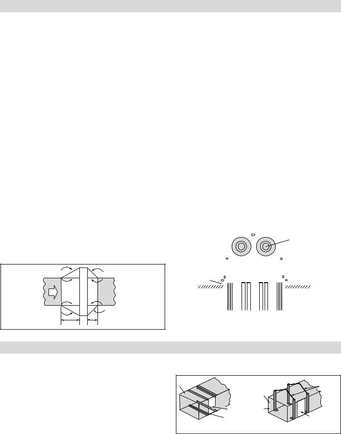
Figure 1 — Dimensions |
|
|
|
|
|
|
|
|
|
|
|
Figure 2 — Dimensions |
|
|
|
|
|
|||||||||||||||
|
|
|
|
|
|
|
|
|
|
|
|
|
|
|
|
|
|
|
|
|
|
|
|
|
|
|
|
|
|
|
|
|
|
|
|
© 2008 Chromalox, Inc.
GENERAL
WARNING: This heater is not intended for use in hazardous atmospheres where flammable vapors, gases, liquids or other combustible atmospheres are present as defined in the National Electrical Code. Failure to comply can result in explosion or fire.
1.Heater construction characteristics —
A.Alloy sheathed tubular elements, .475” diameter
B.Steel flange
C.Stainless steel support construction
D.High temperature alloy terminals and connections
E.Replaceable individual heating elements
F.Wiring terminals located outside the heated zone
2.Maximum Temperatures — Types ADH and ADHT process air heaters can generally be used at the following maximum temperatures shown, provided the minimum air velocity is maintained uniformly through the heater.
Air Velocity |
|
Max. Outlet Air Temp. (˚F) |
|
|
|
|
|
(Ft./Sec.) |
ADH |
|
ADHT |
4 |
800 |
|
1050 |
9 |
800 |
|
1100 |
16 |
800 |
|
1150 |
25 |
800 |
|
1200 |
36 |
800 |
|
1200 |
|
|
|
|
CAUTION: Do not energize heater in air with a velocity less than 1 Ft. Per Second.
3.The heater may be bolted to the duct with the terminal housing and flange at the top, at either side or at the bottom.
4.Several heaters may be mounted in tandem so long as proper controls are used to limit the maximum temperature attained.
5.Installation with duct transitions in some air distribution systems, the duct heater may be considerably larger than the ductwork and the duct area must be increased by a sheet metal transition. The slope of the transformation piece on the upstream side of the equipment is limited to 30° as indicated in Figure 3. On the leaving side, the slope should not be more than 45°.
|
30" |
45˚ |
|
Max |
|
|
Air |
<![if ! IE]> <![endif]>Heater |
|
Flow |
<![if ! IE]> <![endif]>Duct |
|
|
|
|
30˚ |
45˚ |
|
|
Max |
Figure 3 |
4 Ft. Min. |
4 Ft. Min. |
|
|
6.Use moisture proof terminal cover in atmospheres bearing corrosive fumes or excessive moisture.
7.Use explosion resistant heaters in explosive atmospheres and reduce current rating to elements.
8.Gas tight design — Achieved by the use of threaded fittings with fiber washers to attach heating elements to flange — pre vents leakage of ducted air into terminal housing.
9.Overtemperature protection — Thermocouple fastened to the element sheath surface and wired to a terminal block can be provided for accurate overheat protection (standard on ADHT models).
10.Flange mounting gasket — Packed separately with each duct heater to minimize air leakage between the flange and air duct. Refer to Table B and Figure 3.
Specifications — Table B
Flange Gasket |
|
|
|
|
Used On |
|||||
Part No. |
Flange Size |
|
|
|
ADH and ADHT |
|||||
168-055429-001 |
|
|
|
11-1/8 x 5-5/8 |
|
|
|
5 kW |
||
168-055429-002 |
|
|
|
11-1/8 x 7-5/8 |
|
|
|
10 kW |
||
168-055429-003 |
|
|
|
11-1/8 x 9-5/8 |
|
|
|
15 kW |
||
168-055429-004 |
|
|
|
11-1/8 x 11-5/8 |
|
|
|
20 kW |
||
168-055429-005 |
|
|
|
11-1/8 x 13-5/8 |
|
|
|
25 kW |
||
168-055429-006 |
|
|
|
11-1/8 x 15-5/8 |
|
|
|
30 kW |
||
168-055429-007 |
|
|
|
11-1/8 x 17-5/8 |
|
|
|
35 kW |
||
168-055429-008 |
|
|
|
11-1/8 x 19-5/8 |
|
|
|
40 kW |
||
168-055429-009 |
|
|
|
11-1/8 x 21-5/8 |
|
|
|
45 kW |
||
168-055429-010 |
|
|
|
11-1/8 x 23-5/8 |
|
|
|
50 kW |
||
168-055429-011 |
|
|
|
11-1/8 x 27-5/8 |
|
|
|
60, 120 kW |
||
168-055429-013 |
|
|
|
11-1/8 x 35-5/8 |
|
|
|
80, 144, 160 kW |
||
168-055429-014 |
|
|
|
11-1/8 x 39-5/8 |
|
|
|
90, 162, 180 kW |
||
168-055429-015 |
|
|
|
11-1/8 x 43-5/8 |
|
|
|
100 kW |
||
168-055429-017 |
|
|
|
20 x 27-5/8 |
|
|
|
216, 240 kW |
||
168-055429-018 |
|
|
|
20 x 33-5/8 |
|
|
|
270, 300 kW |
||
|
|
|
|
|
|
|
|
|||
|
|
|
|
|
|
|
2-1/2" x 1-1/4" x 3/4" |
|||
|
|
|
|
|
|
|||||
|
|
|
|
|
|
|
|
|
Knockouts |
|
|
Flange |
|
|
|
|
|
|
|
||
|
|
|
|
|
|
|
|
|||
Mounting |
|
|
|
|
|
|
|
|||
|
Gasket |
|
|
|
|
|
|
|
||
|
|
|
|
|
|
|
|
|
|
|
|
|
|
|
|
|
|
|
|
|
|
|
|
|
|
|
|
|
|
|
|
|
|
|
|
|
|
|
|
|
|
Duct Wall |
|
Figure 4 |
|
|
|
|
|
|
||||
|
|
|
|
|
|
|
|
|
|
|
INSTALLATION
WARNING: Hazard of Electric Shock. Disconnect all power before installing heater.
1.Locate and position heater in duct in accordance with both process requirements and recommendations given.
2.Refer to Figures 1 and 2, layout “D” and “M” dimensions on duct mounting face established in step 1.
3.With tools suitable for sheet metal work, cut layout opening in duct.
4.In general, heaters less than 35 pounds in weight may be mounted directly in opening without additional duct reinforcement if duct installation and condition permits. To fasten heater to duct wall use #14 pan or round head self-tapping screws. The flange mounting gasket supplied with the heater is recommended for insertion between heater flange and duct to minimize air leakage.
5.For heater weights greater than 35 pounds (see Specifications Table A, page 1) due consideration should be given to; (a) mechanically strengthening duct work with, for example, angle irons or chains (see Figure 5), and (b) heat insulating duct line
in immediate area of heater location to prevent excessive heat loss. Consult your local sheet metal contractor.
Duct |
Chains |
|
|
|
Duct |
Heater |
Metal |
Opening |
Strapping |
Angle Iron |
Heater Opening |
|
Figure 5
6.In high ambient temperature operations, least corrosive action and least oxidation to the terminals will occur if the heaters are mounted with the terminals in the coolest possible ambient, usually on the bottom or side of the duct.
A.Minimum duct size is “A” or “L” dimension +3/8” and “B” dimension +1-5/8”.
2

INSTALLATION
7.DANGER: Hazard of Fire. Since these heaters are capable of developing high temperatures, extreme care should be taken to:
A.Avoid installing heaters in an atmosphere containing combustible gases and vapors.
B.Avoid contact between heater and combustible material.
C.Keep combustible materials far enough away to be free of the effects of high temperatures.
ADH Low temperature duct heaters — can be fastened directly to the sheet metal duct work with bolts or sheet metal screws.
Duct
Air
Air
Figure 6
ADHT High temperature duct heaters — are generally mounted on field fabricated stand off supports from the ductwork to position the heater such that the 3” insulation housing is in the same plane as the duct insulation.
Duct
Air 
Air |
Standoff Collar |
Insulation
(3" max.)
Figure 7
Temperature Control Instructions
1.A Chromalox thermal cutout or thermostat is recommended for overheat protection and control of heater and process. Consult local Chromalox representative.
2.In general, place thermostat sensing element close to the heating elements, near top of duct, at right angles to the direction of air flow, and on the downstream side of the heater. Thermostat, provided with a manual reset button, is separately mounted.
3.For heater protection, the indicated maximum temperature of the control unit should be 50°F less than the actual maximum air temperature that will be permitted, to allow for overshoot.
4.Single circuit heater elements may be wired into two circuits to allow for partial heating and control. It is important to have thermal control wired into all electric power circuits, so that all elements may be protected from overheat.
WIRING
WARNING: Hazard of Electric Shock. Any installation involving electric heaters must be effectively grounded in accordance with the National Electrical Code to eliminate shock hazard.
1.All wiring should be done in accordance with National Electrical Code and with local codes by a qualified person.
2.Connect air heaters to same line voltage, phase, and frequency as on heater nameplate.
3.Teflon insulated nickel plated copper wire or bus bar is recommended for power connections to heater terminals and for wiring runs in heated zones. When ambient temperature in heated zone exceeds that for which insulated wire is recommended use bare nickel-plated copper with porcelain beads, tubing or bus bar. Consult local Chromalox representative.
4.Users should install adequate back-up controls and safety devices with their electric heating equipment. Selection of controls, thermostat, SCR units, contactors and etc. depends on the degree of accuracy required, reliability, electrical rating of heater and economic considerations.
5.Below is an example of a standard ADH-015, 480V 3 Ø 15 kW,
wired with recommended back-up controls. (Figure 8)
6.Individual terminal blocks with threaded stud type terminals are provided for each circuit to permit quick positive attachment of circuit wiring conductors (one terminal block per circuit). (Figure 9)
L1 |
G |
|
L2 |
L3 |
|
Terminal block (303-027852-001)
X Circuit label indicated here.
Figure 9
ADH-015, 15 kW 480V 3ø, 1 Circuit |
|
|
|
|
|
|
|
|
||
(9) - 480V, 1667 Watt Elements |
|
|
|
|
|
|
|
|
||
|
Magnetic |
|
|
|
||||||
|
|
Fused |
|
|
|
|
||||
|
|
|
Contactor |
Terminal |
||||||
|
|
|
||||||||
|
|
Switch |
|
|
|
|
Block |
|||
L1 |
|
|
|
|
|
|
|
|
L1 |
|
L2 |
|
|
|
|
|
|
|
|
L2 |
|
|
|
|
|
|
|
|
|
|
||
L3 |
|
|
|
|
|
|
|
|
L3 |
|
|
|
|
|
|
|
|
|
|
|
|
|
|
|
|
|
|
|
|
|
|
|
|
|
|
|
|
|
|
|
|
|
|
|
Control |
|
|
|
|
|
|
|
|
|
|
ADH-015 |
|
|
|
|
|
|
|
|
|
||||
|
|
|
|
|
|
|
|
|
|
|
|
|
|
Voltage |
|
|
|
|
|
|
|
|
|
|
|
|
|
|
|
|
|
|
|
|
|
|
|
|
|
120 or 240V |
|
|
|
|
|
|
|
|
|
|
Customer Supplied Wiring |
|
|
|
|
Thermostat |
|
|
|
Factory Supplied Wiring |
||||
Figure 8 |
Control Switch |
|
||||||||||
|
|
|
||||||||||
|
|
|
|
|
|
|
|
|
||||
|
|
|
|
|
|
|
|
|
|
|
|
|
3
 Loading...