


I N S T A L L A T I O N I N S T R U C T I O N S
LARGE FLAT PANEL IN WALL ENCLOSURE
Model: PAC-500
Specifications:
•Designed for in-wall installation spanning a minimum of 3 wood studs, 16" on center.
• Accomodates MWR, PWR and PNR swing arm mounts.
• Cutouts provided for single gang electrical box and grommet hole for audio/video cables.
• Weight capacity of 200 lbs (90 kg).
NOTE: Shown with PNR mount installed; MWR/PWR
mount similar (mount not included).
BEFORE YOU BEGIN
WARNING: It is the installer’s responsibility to make sure all components are properly assembled and installed using the instructions provided. Failure to read, thoroughly understand, and follow all instructions can result in serious personal injury, damage to equipment, or voiding of factory warranty.
•If you have any questions about this these instructions or your specific installation, contact Chief Manufacturing at 1-800-582-6480 or 952-894-6280.
|
|
CHIEF MANUFACTURING INC. |
8800-000058 Rev E |
|
|
1-800-582-6480 952-894-6280 FAX 952-894-6918 |
2007 Chief Manufacturing |
|
|
8401 EAGLE CREEK PARKWAY, STE 700 |
www.chiefmfg.com |
|
|
SAVAGE, MINNESOTA 55378 USA |
06/07 |
|
|
|
|
|
|
|
|
Model: PAC-500 |
Installation Instructions |
 IMPORTANT WARNINGS AND CAUTIONS!
WARNING: A WARNING alerts you to the possibility of serious injury or death if you do not follow the instructions.
CAUTION: A CAUTION alerts you to the possibility of damage or destruction of equipment if you do not follow the corresponding instructions.
WARNING: It is the installer’s responsibility to make sure the structure to which this unit is attached can support five times the combined weight of all equipment. Reinforce the structure as required before installing the unit. Failure to provide adequate structural strength for this unit can result in serious personal injury or damage to equipment!
WARNING: It is the installer’s responsibility to make sure the combined weight of the display, accessories, and any other attached equipment must not exceed 200 lbs (90 kg), the maximum support weight of this unit. Exceeding the maximum support weight can result in serious personal injury or damage to equipment!
WARNING: Make sure the latch securing the display is fully closed at all times except when removing or installing the display. The latch must be fully closed when installing or removing cables from the display.
WARNING: Watch for pinch points. Do not put your fingers between movable parts.
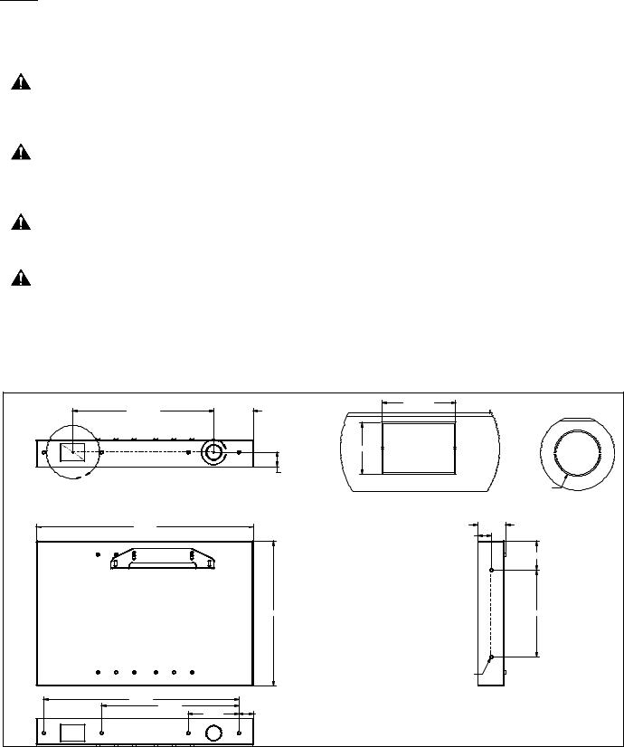
DIMENSIONS |
|
|
|
2 x 19.500 |
2 x 5.500 |
2 x 2.375 |
|
|
|
||
|
B |
2 x 2.375 |
|
|
|
|
|
A |
|
12 x 2.000 |
|
|
|
2 X 2.125 |
|
|
|
|
|
|
|
DETAIL A |
DETAIL B |
|
|
SCALE 1 : 2 |
SCALE 1 : 2 |
30.00 |
|
|
3.855 |
|
|
|
1.875 |
|
|
|
4.000 |
|
|
20.000 |
12.000 |
|
|
|
12 x .390 |
27.000 |
|
|
|
19.000 |
7.000 |
2.000 |
|
|
|
||
2 |
|
|
|

Installation Instructions |
Model: PAC-500 |
TOOLS REQUIRED FOR INSTALLATION |
|
|
|||
• |
Stud Sensor |
|
|
|
|
• |
Level |
|
|
|
|
• |
Saw |
|
|
|
|
• |
Tape Measure |
|
|
|
|
• Screwdriver (for wood screws) |
|
|
|
||
• |
9/16" Wrench |
|
|
|
|
• 3/16" Hex Key (provided) |
|
10 |
|
||
• 4mm Hex Key (provided) |
|
|
|||
|
|
|
|||
• 4mm Hex Bit (provided) |
|
|
|
||
NOTE: Other tools may be required depending on your |
|
|
|||
|
method of installation. |
|
|
60 |
|
PARTS |
|
|
|||
|
|
|
|||
After unpacking carton, inspect and verify contents (See |
|
50 |
|||
Figure 1). If any listed parts are missing or damaged, |
20 |
|
|||
contact Chief Customer Service at 1-800-582-6480. |
|
||||
|
Table 1: Parts |
|
|
|
|
Item |
Description |
Qty |
30 |
|
|
10 |
HOUSING, In-Wall |
1 |
|
|
|
20 |
BRACKET, Upper |
1 |
|
|
|
30 |
BRACKET, Lower (MWR/PWR only) |
1 |
40 |
|
|
40 |
BRACKET, Lower (PNR only) |
1 |
|
||
|
|
||||
50 |
MOULDING, Vertical |
2 |
70 |
|
|
60 |
MOULDING, Horizontal |
2 |
|
|
|
70 |
SCREW, Button Head Cap, 5/16"-18 x 3/4" |
4 |
80 |
140 |
|
80 |
SCREW, Button Head Cap, 3/8"-16 x 5/8" |
4 |
|
||
90 |
SCREW, Flat Head Cap, 3/8"-16 x 3/4" |
2 |
|
150 |
|
100 |
BOLT, Connector, 7mm x 40mm |
12 |
|
||
90 |
|
||||
110 |
WASHER, Flat Machine Screw, 1/4" |
4 |
|
||
|
|
||||
120 |
WASHER, Lock, Split, 5/16" |
4 |
|
160 |
|
130 |
WASHER, Lock, Split, 3/8" |
4 |
100 |
|
|
140 |
PAD, Felt, 1/8" thick |
2 |
170 |
||
|
|||||
150 |
TAPE, Foam, Square |
18 |
|
|
|
160 |
COVER, White, 9/16" diameter |
4 |
110 |
180 |
|
170 |
KEY, Hex, 3/16" (slightly larger than 180 below) |
1 |
|||
180 |
KEY, Hex, 4mm |
1 |
120 |
|
|
190 |
BIT, Hex, 4mm |
1 |
190 |
||
200 |
SHIM, Engineered Wood (package; not shown) |
1 |
|
|
|
201 |
KEY, Hex, 7/32" |
1 |
130 |
|
|
|
SUPPORT BLOCKS, wood 2x4, 8" long |
8 |
|
200 |
|
|
(required, not supplied) |
|
|
|
|
|
HORIZONTAL FRAMING, wood 2x4, 14-1/2" |
4 |
201 |
|
|
|
long; exact length dependent upon specific |
|
|
|
|
|
installation (required, not supplied) |
|
|
|
|
|
SCREW, Wood, #10 x 2-1/2" |
40 |
|
Figure 1: Parts |
|
|
(required, not supplied) |
|
|
|
|
|
ELECTRICAL BOX (optional, not supplied) |
1 |
|
|
|
|
GROMMET (optional, not supplied) |
1 |
|
|
|
3
 Loading...