


I N S T A L L A T I O N I N S T R U C T I O N S
All in One Work Station
KWT-110
KWT-110 |
Installation Instructions |
DISCLAIMER
Milestone AV Technologies, and its affiliated corporations and subsidiaries, (collectively, Milestone) intend to make this manual accurate and complete. However, Milestone makes no claim that the information contained herein covers all details, conditions or variations, nor does it provide for every possible contingency in connection with the installation or use of this product. The information contained in this document is subject to change without notice or obligation of any kind. Milestone makes no representation of warranty, expressed or implied, regarding the information contained herein. Milestone assumes no responsibility for accuracy, completeness or sufficiency of the information contained in this document.
Chief® and Centris® are registered trademarks of Milestone AV Technologies. All rights reserved.
 IMPORTANT WARNINGS AND CAUTIONS!
WARNING: A WARNING alerts you to the possibility of serious injury or death if you do not follow the instructions.
CAUTION: A CAUTION alerts you to the possibility of damage or destruction of equipment if you do not follow the corresponding instructions.
WARNING: Failure to read, thoroughly understand, and follow all instructions can result in serious personal injury, damage to equipment, or voiding of factory warranty! It is the installer’s responsibility to make sure all components are properly assembled and installed using the instructions provided.
WARNING: Failure to provide adequate structural strength for this component can result in serious personal injury or damage to equipment! It is the installer’s responsibility to make sure the structure to which this component is attached can support five times the combined weight of all equipment. Reinforce the structure as required before installing the component. The wall to which the mount is being attached may have a maximum drywall thickness of 5/8" (1.6cm). Do not install drywall anchors into the seam between drywall pieces.
WARNING: Exceeding the weight capacity can result in serious personal injury or damage to equipment! It is the installer’s responsibility to make sure the combined weight of all components attached to the CPU wall mount does not exceed 40 lbs (18.1 kg). The maximum weight of the monitor mount is 25 lbs (11.3 kg). The maximum weight of the keyboard tray is 10 lbs (4.5 kg).
WARNING: Use this mounting system only for its intended use as described in these instructions. Do not use attachments not recommended by the manufacturer.
WARNING: Never operate this mounting system if it is damaged. Return the mounting system to a service center for examination and repair.
WARNING: Do not use this product outdoors.
--SAVE THESE INSTRUCTIONS--
2
Installation Instructions |
KWT-110 |
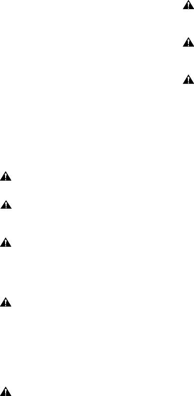
DIMENSIONS |
|
|
|
|
|
|
|
|
|
|
|
|
VERTICAL INSTALLATION |
CABLE |
|
|
|
|
|
CPU WALL MOUNT |
MANAGEMENT |
15 |
|
|
|
|
MAX WEIGHT: 40LBS. |
CHANNELS |
|
|
|
|
|
|
.60 |
DEPTH FROM WALL |
|
|
|
|
|
|
|
|
|
|
||
|
|
TO ACCESSORY |
|
|
|
MONITOR MOUNT |
|
MOUNTING SURFACE |
|
|
|
||
|
|
|
|
|
|
MAX WEIGHT: 25LBS. |
240 |
|
|
|
|
|
|
9.47 |
|
22 |
176 |
|
|
|
|
|
|
|
|
||
|
|
.88 |
|
|
|
|
|
|
6.91 |
254 |
|
|
|
|
|
13 |
|
|
||
|
|
|
10.00 |
|
|
|
|
|
.50 |
|
406 |
KEYBOARD TRAY |
|
|
|
|
|
|||
|
|
|
|
|
16.00 |
|
|
|
114 |
|
|
MAX WEIGHT: 10LBS. |
|
|
|
|
|
|
|
|
|
|
4.50 |
|
|
|
|
|
|
|
|
|
|
HORIZONTAL INSTALLATION |
918 |
|
6 |
|
|
|
|
36.15 |
|
.25 TYP. |
|
508 |
|
|
|
|
HOLE SIZE |
|
813 |
|
|
|
|
|
|
20.00 |
|
|
|
|
|
|
32.00 |
|
|
|
|
|
|
|
|
|
|
FLEXIBLE/REMOVEABLE |
|
|
|
|
|
|
CABLE MANAGEMENT |
|
|
|
|
|
|
COVERS |
|
|
|
|
|
3
KWT-110 |
Installation Instructions |
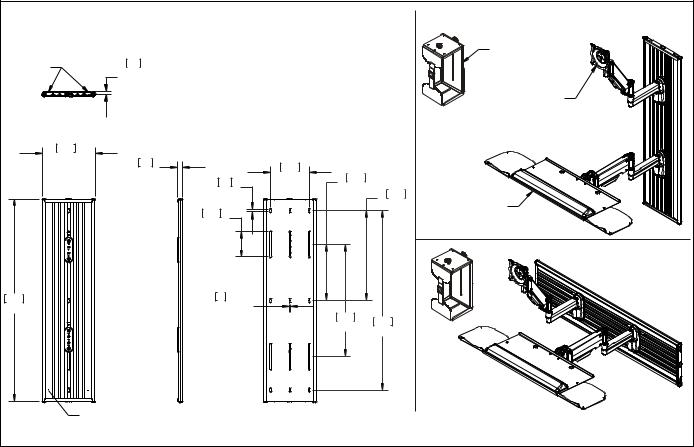
DIMENSIONS |
|
|
|
|
|
90 |
PIVOT |
180 |
|
|
|
60 |
|
|
|
|
|
2.36 |
|
|
|
|
|
RETRACTED |
19.45 |
|
|
|
|
|
|
|
LIFT ARM |
|
|
|
|
|
13.25" VERTICAL RANGE |
|
|
|
[254] |
41 |
|
|
|
|
1.63 |
|
|
||
|
10.0 |
|
|
||
|
|
|
|
||
165 |
|
|
|
|
VESA STANDARD |
6.50 |
|
|
|
|
75mm 100mm |
|
|
|
|
|
|
33 |
|
|
|
|
|
1.30 |
|
|
|
|
|
|
|
|
268 |
|
|
|
|
|
10.57 |
|
|
144 |
143 |
|
|
|
|
5.67 |
5.63 |
|
|
|
|
|
|
|
|
61 |
|
|
|
|
|
2.40 |
|
|
|
|
|
6.50 |
|
|
|
|
|
WRISTPAD |
|
|
|
|
|
(REMOVABLE) |
|
|
|
|
|
18.75 |
|
EXTENDED |
|
|
|
|
COLLAPSED |
|
|
|
29.14 |
KEYBOARD TRAY ANGLE |
|
|
|
|
|
||
|
|
|
|
ADJUSTABLE |
15 |
6.15 |
|
|
|
|
|
4 |
|
|
|
|
|
Installation Instructions |
KWT-110 |
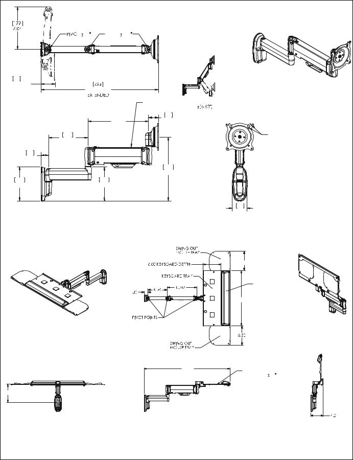
DIMENSIONS |
|
|
|
COMPONENT |
|
|
|
MOUNTING |
|
|
|
BRACKET |
|
|
|
OPTIONS |
|
|
|
"X" |
|
|
|
DRYWALL |
|
|
|
MINIMUM DISTANCE BETWEEN |
|||
COMPONENT MOUNTING |
|||
BRACKETS IN HORIZONTAL |
|||
CONFIGURATION |
|||
INSTALLATION |
X |
AVAILABLE |
|
OPTIONS |
ADJUSTMENT |
||
|
|||
STEEL STUD |
8" |
23" |
|
WOOD STUD |
|
|
|
BRACKET |
|
|
|
[0 - 191] |
|
|
|
0" - 8.50" |
|
|
|
WIDTH OF |
|
|
|
CPU RANGE |
|
|
|
[248 - 457] |
|
|
|
CPU RANGE |
7 |
|
|
.26 |
|
||
|
|
||
MOUNTING |
|||
HOLES |
|
||
|
|
5 |
|

KWT-110 |
Installation Instructions |
LEGEND |
|
Tighten Fastener |
Pencil Mark |
Apretar elemento de fijación |
Marcar con lápiz |
Befestigungsteil festziehen |
Stiftmarkierung |
Apertar fixador |
Marcar com lápis |
Serrare il fissaggio |
Segno a matita |
Bevestiging vastdraaien |
Potloodmerkteken |
Serrez les fixations |
Marquage au crayon |
Loosen Fastener |
Drill Hole |
Aflojar elemento de fijación |
Perforar |
Befestigungsteil lösen |
Bohrloch |
Desapertar fixador |
Fazer furo |
Allentare il fissaggio |
Praticare un foro |
Bevestiging losdraaien |
Gat boren |
Desserrez les fixations |
Percez un trou |
Phillips Screwdriver |
Adjust |
Destornillador Phillips |
Ajustar |
Kreuzschlitzschraubendreher |
Einstellen |
Chave de fendas Phillips |
Ajustar |
Cacciavite a stella |
Regolare |
Kruiskopschroevendraaier |
Afstellen |
Tournevis à pointe cruciforme |
Ajuster |
Open-Ended Wrench |
Remove |
Llave de boca |
Quitar |
Gabelschlüssel |
Entfernen |
Chave de bocas |
Remover |
Chiave a punte aperte |
Rimuovere |
Steeksleutel |
Verwijderen |
Clé à fourche |
Retirez |
By Hand |
Optional |
A mano |
Opcional |
Von Hand |
Optional |
Com a mão |
Opcional |
A mano |
Opzionale |
Met de hand |
Optie |
À la main |
En option |
Hex-Head Wrench |
Security Wrench |
Llave de cabeza hexagonal |
Llave de seguridad |
Sechskantschlüssel |
Sicherheitsschlüssel |
Chave de cabeça sextavada |
Chave de segurança |
Chiave esagonale |
Chiave di sicurezza |
Zeskantsleutel |
Veiligheidssleutel |
Clé à tête hexagonale |
Clé de sécurité |
6 |
|
Installation Instructions |
KWT-110 |
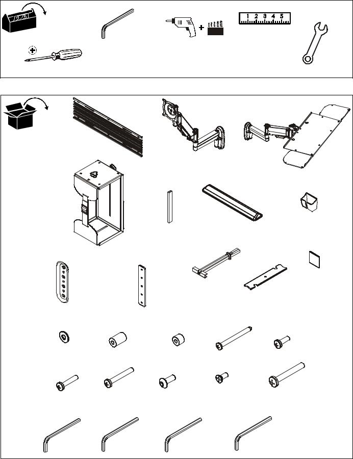
TOOLS REQUIRED FOR INSTALLATION
|
3/32" (included) |
|
7/64" |
|
|
|
|
|
|
17/64" |
|
|
|
7/16" |
|
|
1/8" (included) |
|
|
|
|
||
|
|
1/2" |
|
|
|
|
|
|
3/16" (included) |
|
|
|
|
|
|
|
|
|
|
|
|
|
|
#2 |
5/32" (included) |
|
|
|
|
|
|
PARTS |
|
|
|
|
|
|
|
A (1) |
|
|
|
|
|
|
|
[Wall track accessory] |
|
B (1) |
|
|
|
|
|
|
|
|
|
|
|
|
|
|
|
[Centris display mount] |
|
|
|
||
|
|
|
|
|
|
|
C (1) |
|
|
|
|
|
|
|
[Keyboard tray mount] |
D (1) |
|
|
|
|
|
|
|
[CPU mount] |
|
|
|
F (1) |
|
|
|
|
|
|
[Gel wrist pad] |
|
|
G (1) |
|
|
|
E (4) |
|
|
|
[Mouse holder] |
|
|
|
|
|
|
|
||
|
|
[3" rubber edging] |
|
|
|
|
|
|
|
|
|
|
|
|
M (6) |
|
|
|
K (8) |
|
|
|
[Hook and loop |
|
|
|
|
|
L (2) |
fastener] |
|
|
|
|
1/4-20" |
|
|
||
|
|
|
|
|
|
||
|
|
|
|
[Cable management cover] |
|||
H (2) |
J (2) |
|
|
|
|
|
|
[Wall plate] |
|
|
|
|
|
||
[Locking plate bracket] |
|
|
|
|
|
||
|
|
|
|
|
|
||
N (6) |
P (4) |
Q (4) |
R (6) |
|
|
S (4) |
|
#10 |
.50 x .194 x .75 |
.50 x .194 x .375 |
#12 x 2-1/2" |
|
|||
|
|
|
M4 x 12mm |
||||
|
U (4) |
V (6) |
|
W (4) |
|
|
X (8) |
|
|
|
|
1/4-20 x 1-3/4" |
|||
T (4) |
#8-32 x 3/8" |
|
|
||||
M4 x 30mm |
|
|
|
|
|||
M4 x 20mm |
#10-24 x 1/2" |
|
|
|
|
||
|
|
|
|
|
|
|
|
Y (1) |
Z (1) |
|
AA (1) |
|
BB (1) |
|
|
3/32" |
3/16" |
|
5/32" |
|
|
1/8" |
|
|
|
|
|
|
|
|
7 |
KWT-110 |
Installation Instructions |
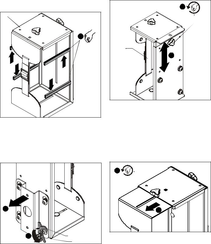
ASSEMBLY AND INSTALLATION - CPU MOUNT
Installation of Protective Rubber Edging
1.Place four strips of protective rubber edging (E) over the sharp edges located on the top and bottom of the CPU mount (D). (See Figure 1)
(D) |
1 |
(E) x 4 |
Figure 1
CPU Installation
2.Release bracket from mount by moving the flag to the open position. (See Figure 2)
3.Remove bracket from mounting buttons on back of mount. (See Figure 2)
2 |
|
1 |
Latch closed |
|
Latch open |
Figure 2
4.Loosen adjustment knob at the back of the mounting unit and adjust height of mount to a height greater than the height of the CPU to be installed. Loosen strap at the front of the mount if necessary. (See Figure 3)
3
Strap
3
Figure 3
5.Loosen adjustment knobs on top and bottom of the mount and slide flanges in order to allow for the CPU to be inserted for mounting. (See Figure 4)
NOTE: Top and bottom knobs can be removed and inserted into the front square holes in order to allow for large CPU’s to be installed. (See Figure 4)
NOTE: Flanges may be reversed in order to allow for narrow CPU’s to be installed in a secure manner. If this is done, be sure to also to remove and reinstall strap so that the buckle is facing out for easy adjustment.
4 |
4 |
Figure 4
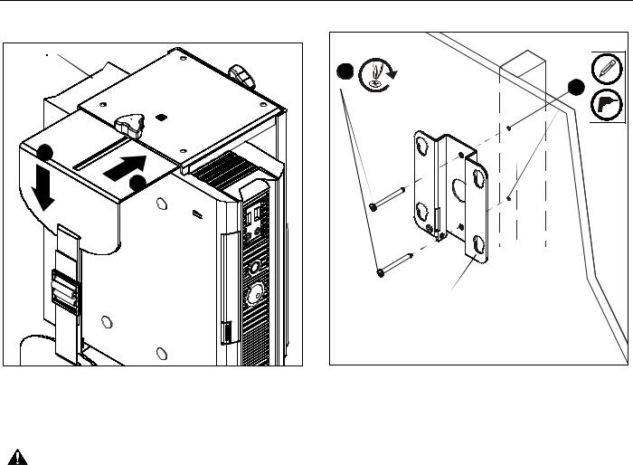
6.Set CPU within mount (D). (See Figure 5)
8
Installation Instructions |
KWT-110 |
|
7. |
Use adjustment knobs to compress mount around CPU until |
|
|
CPU is tightly secured within mount (D). (See Figure 5) |
|
|
CPU |
|
|
3 |
(R) x 2 |
|
|
2 |
|
6 |
|
|
6 |
|
|
|
mounting bracket |
Figure 5
8.Tighten front strap to desired tension.
CPU WALL MOUNT INSTALLATION
WARNING: FAILURE TO PROVIDE ADEQUATE STRUCTURAL STRENGTH FOR THIS MOUNT CAN RESULT IN SERIOUS PERSONAL INJURY OR DAMAGE TO EQUIPMENT! It is the installer’s responsibility to make sure the structure to which this mount is attached can support five times the combined weight of the mount and all equipment attached to it. Reinforce the structure as required before installing the mount.
NOTE: Mount may be installed using wood studs, steel studs or it may be installed directly into drywall. For steel stud and drywall installation, proceed ahead to Site Requirements for Using Steel Studs section. For desk mounting, proceed ahead to Desk Mounting Installation section.
CPU Mount Installation Using Wood Studs
1.Determine location for mount keeping in mind CPU size and safety requirements.
2.Using the removed mounting bracket as a template, mark and then drill two 7/64" diameter pilot holes through top and bottom holes of wall bracket into wall. (See Figure 6)
Figure 6
3.Install two #12 x 2 1/2" round Phillips wood screws (R) through bracket and drywall into wood stud. (See Figure 6)
4.Ensure bracket is vertical, then tighten screws (R).
NOTE: Proceed ahead to Mounting CPU to Wall section to complete installation.
9
 Loading...