


I N S T A L L A T I O N I N S T R U C T I O N S I N S T R U C T I O N S D ' I N S T A L L A T I O N M O N T A G E A N L E I T U N G
Universal HB Interface
Interface universelle HB
HB-Universalanschlussplatte
HBU
HBU |
Installation Instructions |
DISCLAIMER
Milestone AV Technologies and its affiliated corporations and subsidiaries (collectively "Milestone"), intend to make this manual accurate and complete. However, Milestone makes no claim that the information contained herein covers all details, conditions or variations, nor does it provide for every possible contingency in connection with the installation or use of this product. The information contained in this document is subject to change without notice or obligation of any kind. Milestone makes no representation of warranty, expressed or implied, regarding the information contained herein. Milestone assumes no responsibility for accuracy, completeness or sufficiency of the information contained in this document.
Chief® is a registered trademark of Milestone AV Technologies. All rights reserved.
 IMPORTANT SAFETY INSTRUCTIONS
WARNING: A WARNING alerts you to the possibility of serious injury or death if you do not follow the instructions.
CAUTION: A CAUTION alerts you to the possibility of damage or destruction of equipment if you do not follow the corresponding instructions.
WARNING: Failure to read, thoroughly understand, and follow all instructions can result in serious personal injury, damage to equipment, or voiding of factory warranty! It is the installer’s responsibility to make sure all components are properly assembled and installed using the instructions provided.
WARNING: Failure to provide adequate structural strength for this component can result in serious personal injury or damage to equipment! It is the installer’s responsibility to make sure the structure to which this component is attached can support five times the combined weight of all equipment. Reinforce the structure as required before installing the component.
WARNING: Exceeding the weight capacity can result in serious personal injury or damage to equipment! It is the installer’s responsibility to make sure the weight of the projector attached to the HBU interface bracket does not exceed 250 lbs (113.4 kg).
WARNING: Use this mounting system only for its intended use as described in these instructions. Do not use attachments not recommended by the manufacturer.
WARNING: Never operate this mounting system if it is damaged. Return the mounting system to a service center for examination and repair.
WARNING: Do not use this product outdoors.
IMPORTANT ! : These instructions assume that an appropriate mounting method (not included) has already been properly installed to a ceiling structure.
--SAVE THESE INSTRUCTIONS--
2

Installation Instructions |
HBU |
|
DIMENSIONS |
|
|
665.7 |
|
|
26.21 |
|
|
MAX DEPTH |
|
|
745.1 |
|
|
29.33 |
|
|
MAX WIDTH |
|
|
|
.50 |
|
|
INCLUDES M4, M5, |
|
|
M6, M8, M10, AND |
|
|
M12 SCREWS |
|
36 |
|
|
1.42 |
|
|
MINIMUM |
|
|
HEIGHT |
|
|
51.9 |
DIMENSIONS: [MILLIMETERS] |
|
2.04 |
||
MAXIMUM |
INCHES |
|
HEIGHT |
||
|
||
LEGEND |
|
Tighten Fastener |
Adjust |
Apretar elemento de fijación |
Ajustar |
Befestigungsteil festziehen |
Einstellen |
Apertar fixador |
Ajustar |
Serrare il fissaggio |
Regolare |
Bevestiging vastdraaien |
Afstellen |
Serrez les fixations |
Ajuster |
Loosen Fastener |
Open-Ended Wrench |
Aflojar elemento de fijación |
Llave de boca |
Befestigungsteil lösen |
Gabelschlüssel |
Desapertar fixador |
Chave de bocas |
Allentare il fissaggio |
Chiave a punte aperte |
Bevestiging losdraaien |
Steeksleutel |
Desserrez les fixations |
Clé à fourche |
Phillips Screwdriver |
Hex-Head Wrench |
Destornillador Phillips |
Llave de cabeza hexagonal |
Kreuzschlitzschraubendreher |
Sechskantschlüssel |
Chave de fendas Phillips |
Chave de cabeça sextavada |
Cacciavite a stella |
Chiave esagonale |
Kruiskopschroevendraaier |
Zeskantsleutel |
Tournevis à pointe cruciforme |
Clé à tête hexagonale |
|
3 |
HBU |
Installation Instructions |
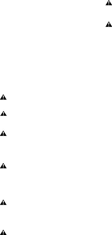
TOOLS REQUIRED FOR INSTALLATION
|
1/2" |
|
|
|
|
PARTS |
|
|
|
|
|
BAG A |
|
BAG B |
|
BAG C |
|
|
BA (8) |
|
CA (8) |
|
|
A (8) |
M6 x 16mm |
|
M8 x 12mm |
CC (8) |
|
M5 x 20mm |
|
|
|
|
M8 |
|
|
BB (8) |
|
CB (8) |
|
|
|
|
M8 x 16mm |
||
|
|
M6 x 25mm |
|
||
|
|
|
|
|
|
|
|
FA (8) |
|
|
JA (8) |
|
|
|
|
M4x16mm |
|
D (8) |
|
5/16" |
G (8) |
|
|
E (8) |
|
|
|||
M10 x 20mm |
|
[Nesting washer] |
|
|
|
M12 x 20mm |
|
H (4) |
|
||
|
|
|
JB (8) |
||
|
|
FB (8) |
|
||
|
|
|
5/16" |
||
BAG D |
BAG E |
5/16" |
BAG G |
BAG H |
M5 |
BAG F |
BAG J |
||||
|
|
|
|
|
L (8) |
|
|
|
|
|
[HBU leg] |
K (1) |
|
|
|
|
|
[HB plate] |
|
|
|
|
|
4 |
|
|
|
|
|
Installation Instructions |
HBU |
INSTALLATION
WARNING: FAILURE TO PROVIDE ADEQUATE STRUCTURAL STRENGTH FOR THIS COMPONENT CAN RESULT IN SERIOUS PERSONAL INJURY OR DAMAGE TO EQUIPMENT! It is the installer’s responsibility to make sure the structure to which this component is attached can support five times the combined weight of all equipment. Reinforce the structure as required before installing the component.
Installing VCM Ceiling Mount
Install the VCM ceiling mount (not included) to the structure following instructions included with the VCM mount.
Installing HBU Bracket
WARNING: IMPROPER INSTALLATION CAN LEAD TO PROJECTOR FALLING CAUSING SERIOUS PERSONAL INJURY OR DAMAGE TO EQUIPMENT! Using screws of improper size may damage your projector. Properly sized screws will easily and completely thread into projector mounting holes.
1.Select correct screws and washers from the hardware bags (A, B, C, D, E, G, J). (See Table 1)
|
Table 1 |
|
|
Fastener Size |
Washer |
|
|
M4x16mm (JA) |
M4 washer (JB), Nesting Washer (G) |
|
|
M5x20mm (A) |
Nesting Washer (G) |
M6x16mm (BA) |
Nesting Washer (G) |
M6x25mm (BB) |
Nesting Washer (G) |
|
|
M8x12mm (CA) |
M8 washer (CC) |
M8x16mm (CB)M8 |
M8 washer (CC) |
|
|
M10x20mm (D) |
No washer |
M12x20mm (E) |
No washer |
|
|
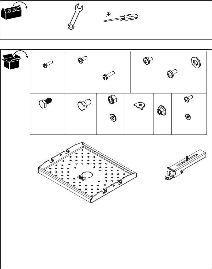
2.Attach HBU legs (L) to projector using selected fasteners and washers. (See Figure 1) and (See Figure 2)
WARNING: One HBU leg should be attached to each available mounting hole in the projector. A minimum of three legs must be used if using M5 or larger fasteners. A minimum of four legs must be used if using M4 fasteners.
[Example
using nesting 2 washers (G)]
Projector
(A, BA, BB or JA)
x number of legs (L)
 (G)
(G)
(JB) with (JA) only
(L)
Nesting washer in place
|
|
Figure 1 |
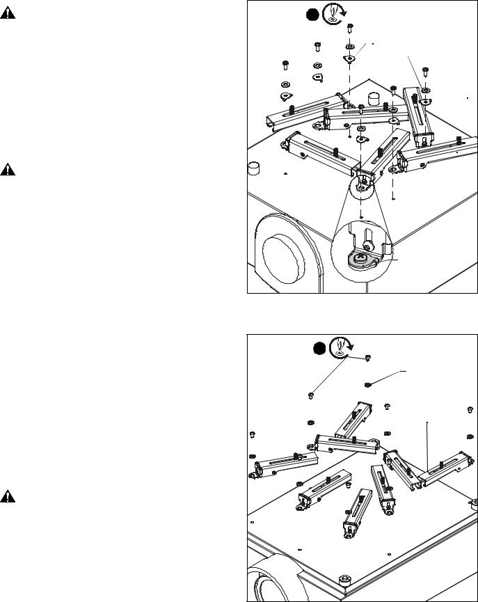
[Example |
2 |
(CA or CB) x number of legs (L) |
using M8 flat |
washers (CC)]
(CC)
(L)
Projector
Figure 2
5
 Loading...