


90 AMP FLUX WIRE WELDER

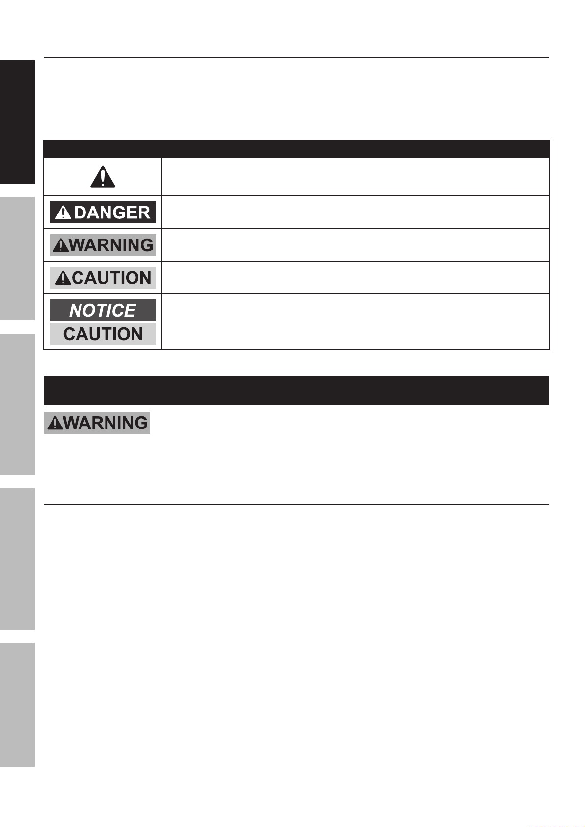
Table of Contents
Safety ......................................................... 2
Specifications ............................................. 6
SAFETY MAINTENANCEBASIC WELDING WELDING TIPSSETUP
Setup .......................................................... 7
Basic Welding ............................................ 12
Welding Tips .............................................. 18
Maintenance .............................................. 22
Parts List and Diagrams ............................ 25
Warranty .................................................... 28
WARNING SYMBOLS AND DEFINITIONS
This is the safety alert symbol. It is used to alert you to potential
personal injury hazards. Obey all safety messages that
follow this symbol to avoid possible injury or death.
Indicates a hazardous situation which, if not avoided,
will result in death or serious injury.
Indicates a hazardous situation which, if not avoided,
could result in death or serious injury.
Indicates a hazardous situation which, if not avoided,
could result in minor or moderate injury.
Addresses practices not related to personal injury.
IMPORTANT SAFETY INFORMATION
Read all safety warnings and instructions.
Failure to follow the warnings and instructions may result in electric shock, fire and/or serious injury.
Save all warnings and instructions for future reference.
General Safety Information
PROTECT yourself and others. Read and understand this information.
1. Before use, read and understand
manufacturer′s instructions,
Material Safety Data Sheets (MSDS),
employer′s safety practices, and ANSI Z49.1.
2. Keep out of reach of children.
Keep children and bystanders away while operating.
3. Place the Welder on a stable location before use.
If it falls while plugged in, severe injury,
electric shock, or fire may result.
4. Stay alert, watch what you are doing and use
common sense when operating a welder.
Do not use a welder while you are tired or under
the influence of drugs, alcohol or medication.
A moment of inattention while operating welders
may result in serious personal injury.
5. Do not overreach.
Keep proper footing and balance at all times.
6. Avoid unintentional starting. Make sure you are
prepared to begin work before turning on the Welder.
7. Never leave the Welder unattended while
energized. Turn power off if you have to leave.
8. The warnings, precautions, and instructions
discussed in this instruction manual cannot
cover all possible conditions and situations
that may occur. It must be understood by the
operator that common sense and caution are
factors which cannot be built into this product,
but must be supplied by the operator.
Page 2 For technical questions, please call 1-800-444-3353. Item 68887
9. This product, when used for welding and similar
applications, contains or produces a chemical
known to the State of California to cause cancer
and birth defects (or other reproductive harm).
(California Health & Safety Code § 25249.5, et seq.)
Fume and Gas Safety Information
10. Handling the cord on this product will expose
you to lead, a chemical known to the State of
California to cause cancer, and birth defects or
other reproductive harm.
Wash hands after handling.
(California Health & Safety Code § 25249.5, et seq.)
FUMES AND GASES can be hazardous to your health.
1. Exposure to welding or cutting
exhaust fumes can increase the risk
of developing certain cancers, such as
cancer of the larynx and lung cancer.
Also, some diseases that may be linked to
exposure to welding or cutting exhaust fumes are:
• Early onset of Parkinson’s Disease
• Heart disease • Ulcers
• Damage to the reproductive organs
• Inflammation of the small intestine or
stomach • Kidney damage
• Respiratory diseases such as
emphysema, bronchitis, or pneumonia
2. Do not use near degreasing or
painting operations.
3. Keep head out of fumes.
Do not breathe exhaust fumes.
SAFETYMAINTENANCE BASIC WELDINGWELDING TIPS SETUP
4. Use enough ventilation, exhaust at arc, or
both, to keep fumes and gases from breathing
zone and general area. If engineering controls
are not feasible, use an approved respirator.
5. Work in a confined area only if it
is well-ventilated, or while wearing
an air-supplied respirator.
6. Have a recognized specialist in
Industrial Hygiene or Environmental Services
check the operation and air quality
and make recommendations
for the specific welding situation.
Follow OSHA guidelines for
Permissible Exposure Limits (PEL’s) and
the American Conference of Governmental
Industrial Hygienists recommendations for
Threshold Limit Values (TLV’s) for fumes and gases.
Arc Ray Safety Information
ARC RAYS can injure eyes and burn skin.
1. Wear ANSI-approved welding eye protection
featuring at least a number 10 shade lens rating.
2. Wear leather leggings, fire resistant shoes
or boots during use. Do not wear pants with
cuffs, shirts with open pockets, or any clothing
that can catch and hold molten metal or sparks.
3. Keep clothing free of grease, oil,
solvents, or any flammable substances.
Wear dry, insulating gloves and protective clothing.
4. Wear an approved head covering to protect
the head and neck. Use aprons, cape, sleeves,
shoulder covers, and bibs designed and
approved for welding and cutting procedures.
5. When welding/cutting overhead or in confined
spaces, wear flame resistant ear plugs or
ear muffs to keep sparks out of ears.
Page 3For technical questions, please call 1-800-444-3353.Item 68887
Electrical Safety Information
SAFETY MAINTENANCEBASIC WELDING WELDING TIPSSETUP
1. Turn off, disconnect power, and
discharge electrode to ground before setting
down torch/electrode holder and before service.
2. Do not touch energized electrical parts.
Wear dry, insulating gloves. Do not touch electrode
holder, electrode, welding torch, or welding wire with
bare hand. Do not wear wet or damaged gloves.
3. Connect to grounded, GFCI-protected
power supply only.
4. Do not use near water or damp objects.
5. People with pacemakers should consult their
physician(s) before use. Electromagnetic fields
in close proximity to heart pacemaker could cause
pacemaker interference or pacemaker failure.
6. Do not expose welders to rain or wet conditions.
Water entering a welder will increase
the risk of electric shock.
ELECTRIC SHOCK can KILL.
7. Do not abuse the cord. Never use the cord
for carrying, pulling or unplugging the Welder.
Keep cord away from heat, oil, sharp edges
or moving parts. Damaged or entangled
cords increase the risk of electric shock.
8. Do not use outdoors.
9. Insulate yourself from the workpiece and
ground. Use nonflammable, dry insulating
material if possible, or use dry rubber mats,
dry wood or plywood, or other dry insulating
material large enough to cover your full
area of contact with the work or ground.
10. Use care not to touch the welding tip to
grounded material whenever the unit is
plugged in. Electric shock, fire, or burns may
happen if appropriate precautions are not taken.
Fire Safety Information
ARC AND HOT SLAG can cause fire.
1. Clear away or protect flammable objects.
Remove or make safe all combustible materials for a
radius of 35 feet (10 meters) around the work area.
Use a fire resistant material to cover
or block all open doorways, windows,
cracks, and other openings.
2. Keep ABC-type fire extinguisher near
work area and know how to use it.
3. Maintain a safe working environment.
Keep the work area well lit.
Make sure there is adequate
surrounding workspace. Keep the work area free
of obstructions, grease, oil, trash, and other debris.
4. Do not operate welders in atmospheres
containing dangerously reactive or
flammable liquids, gases, vapors, or dust.
Provide adequate ventilation in work areas
to prevent accumulation of such substances.
Welders create sparks which may ignite flammable
substances or make reactive fumes toxic.
5. If working on a metal wall, ceiling, etc.,
prevent ignition of combustibles on the
other side by moving the combustibles to a
safe location. If relocation of combustibles is
not possible, designate someone to serve as
a fire watch, equipped with a fire extinguisher,
during the cutting process and for at least one
half hour after the cutting is completed.
6. Do not weld or cut on materials having
a combustible coating or combustible
internal structure, as in walls or ceilings, without
an approved method for eliminating the hazard.
7. Do not dispose of hot slag in containers
holding combustible materials.
8. After welding, make a thorough examination
for evidence of fire. Be aware that easily
visible smoke or flame may not be present
for some time after the fire has started.
9. Do not apply heat to a container that has held
an unknown substance or a combustible
material whose contents, when heated,
can produce flammable or explosive vapors.
Clean and purge containers before applying heat.
Vent closed containers, including castings,
before preheating, welding, or cutting.
Page 4 For technical questions, please call 1-800-444-3353. Item 68887

Operation Specific Safety Information
1. Do not use the Welder if the switch does not turn
it on and off. Any welder that cannot be controlled
with the switch is dangerous and must be repaired.
2. Disconnect the plug from the power
source before making any adjustments,
changing accessories, or storing welders.
Such preventive safety measures reduce the
risk of starting the Welder accidentally.
3. Prevent unintentional starting.
Ensure the switch is in the off-position before
connecting to power source or moving
the Welder. Carrying or energizing welders
that have the switch on invites accidents.
Service Specific Safety Information
1. Maintain welders. Check for misalignment or
binding of moving parts, breakage of parts
and any other condition that may affect the
Welder’s operation. If damaged, have the
Welder repaired before use. Many accidents
are caused by poorly maintained welders.
2. Have your Welder serviced by a qualified
repair person using only identical
replacement parts. This will ensure that
the safety of the Welder is maintained.
4. Store idle Welder out of the reach of
children and do not allow persons unfamiliar
with the Welder or these instructions to
operate the Welder. Welders are dangerous
in the hands of untrained users.
5. Use the Welder and accessories in
accordance with these instructions, taking
into account the working conditions and
the work to be performed. Use of the Welder
for operations different from those intended
could result in a hazardous situation.
3. Maintain labels and nameplates on the Welder.
These carry important information.
If unreadable or missing, contact
Harbor Freight Tools for a replacement.
4. Unplug before maintenance. Unplug the Welder
from its electrical outlet before any inspection,
maintenance, or cleaning procedures.
SAFETYMAINTENANCE BASIC WELDINGWELDING TIPS SETUP
SAVE THESE INSTRUCTIONS.
Page 5For technical questions, please call 1-800-444-3353.Item 68887
Grounding
SAFETY MAINTENANCEBASIC WELDING WELDING TIPSSETUP
TO PREVENT ELECTRIC SHOCK AND DEATH FROM INCORRECT GROUNDING WIRE
CONNECTION:
Check with a qualified electrician if you are in doubt as to whether the outlet is properly
grounded. Have a plug installed by a certified electrician. Do not use the Welder if the power
cord or plug is damaged. If damaged, have it repaired by a service facility before use. If the plug will not fit
the outlet, have a proper outlet installed by a qualified electrician.
Grounded Welders
1. The grounding prong in the plug is connected
through the green wire inside the cord to the
grounding system in the Welder. The green wire
in the cord must be the only wire connected to
the Welder’s grounding system and must never
be attached to an electrically “live” terminal.
2. The Welder must be plugged into an appropriate
outlet, properly installed and grounded in
accordance with all codes and ordinances.
Extension Cords
1. If an extension cord is used, it must have
the following wire size: up to 30 feet, use
10 AWG size wire; 30 to 50 feet, use 8 AWG
wire; Over 50 feet, use 6 AWG wire.
2. As the distance from the supply outlet increases,
you must use a heavier gauge extension cord.
Using extension cords with inadequately sized
wire causes a serious drop in voltage, resulting
in loss of power and possible Welder damage.
3. The smaller the gauge number of the wire,
the greater the capacity of the cord. For
example, a 14 gauge cord can carry a
higher current than a 16 gauge cord.
4. When using more than one extension cord to
make up the total length, make sure each cord
contains at least the minimum wire size required.
5. If you are using one extension cord for more than
one welder, add the nameplate amperes and use the
sum to determine the required minimum cord size.
6. If you are using an extension cord outdoors, make
sure it is marked with the suffix “W-A” (“W” in
Canada) to indicate it is acceptable for outdoor use.
7. Make sure the extension cord is properly wired
and in good electrical condition. Always replace
a damaged extension cord or have it repaired
by a qualified electrician before using it.
8. Protect the extension cords from sharp objects,
excessive heat, and damp or wet areas.
Specifications
Electrical Rating 120 V~ / 20 A
Welding Output 60 ~ 120 A, AC
Capacity
Duty Cycle
Open Circuit Voltage 27
KVA 2.38
Welder Tips / Wire Size Installed tip will accept 0.030" Flux-Core wire
Wire Spool Capacity 4" diameter / 2 lb. spool
Page 6 For technical questions, please call 1-800-444-3353. Item 68887
18 gauge (0.048") to 3/16" (0.19") mild steel only
Not for welding aluminum or stainless steel
20% @ 90 A
(See explanation on page 14)
Symbology
Setup
V
Wire Feed (Speed)
Workpiece Ground Cable
Gun Cable
Overheat Shutdown Indicator
Cooling Fan
Housing Ground Point
Volts
~
A
OCV
KVA
IPM
AWG
Alternating Current
Amperes
Open Circuit Voltage
Kilovolt Amperes
(Volts / 1000 * Amperes)
Inches Per Minute
American Wire Gauge
SAFETYMAINTENANCE BASIC WELDINGWELDING TIPS SETUP
Read the ENTIRE IMPORTANT SAFETY INFORMATION section at the beginning of this
manual including all text under subheadings therein before set up or use of this product.
TO PREVENT SERIOUS INJURY FROM ACCIDENTAL OPERATION:
Turn the Power Switch off and unplug the Welder before assembly.
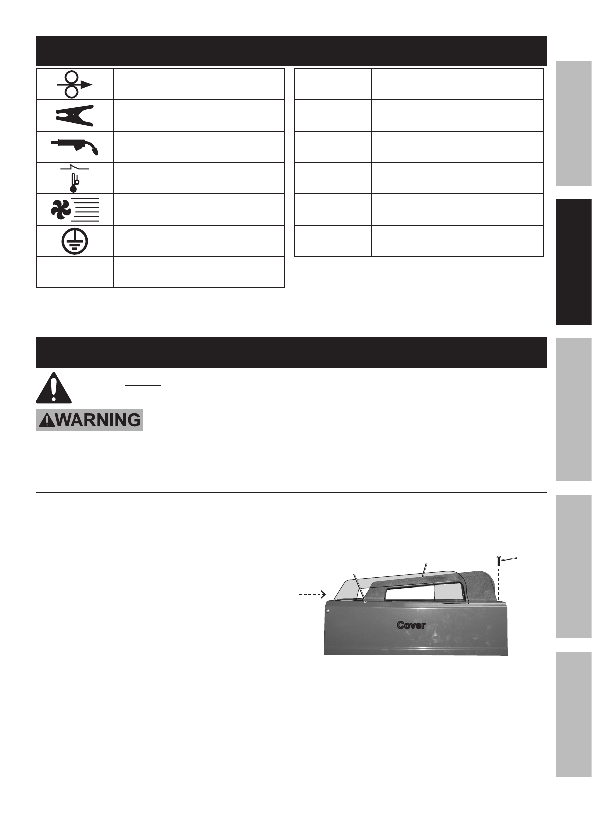
Cover Assembly
1. Slide the Handle into the slot on
the Cover from the back.
2. The notch on the front of the Handle should drop
into the slot in the Cover. Both ends of the Handle
should lay flush against the top of the Cover.
3. Secure with Screw at front of unit.
Notch drops
into slot on
Cover here
Handle
Cover
Screw
Page 7For technical questions, please call 1-800-444-3353.Item 68887
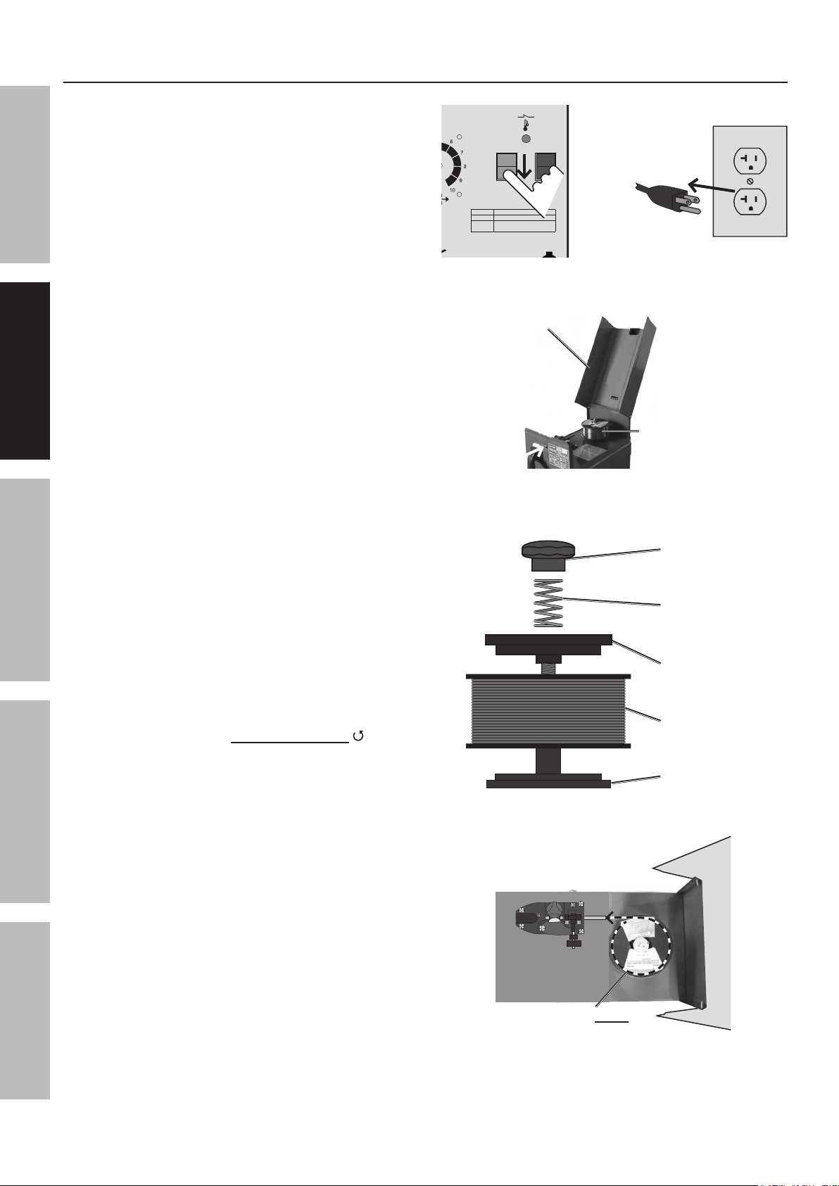
Wire Spool Installation
SAFETY MAINTENANCEBASIC WELDING WELDING TIPSSETUP
1. Turn the Welder to OFF and unplug
it before proceeding.
2. Press in the pin at the top center of
the control panel and open the Cover.
ITEM 68887
ON MIN
OFF MAX
Specications
Wire 0.030" – 0.035" Flux-Core
Capacity 18 Ga. – 3/16" Steel Plate
Weldable
Mild, Low Alloy Steel
(Not for Aluminum or Stainless Steel)
Materials
Cover
Wire
Spool
3. Remove the Knob, Spring and the Top Plate.
If replacing a Spool, remove the old Spool
and all remaining wire from the liners.
4. Place the new flux-core Wire Spool
over the Spool Spindle.
To prevent wire feed problems, set the Spool
so that it will unwind counterclockwise .
5. Replace the Top Plate (turned as shown in
illustration), the Spring and the Knob.
Knob
Spring
Top Plate
Wire Spool
Spindle
.030″
wire must
unwind in this
direction
Page 8 For technical questions, please call 1-800-444-3353. Item 68887
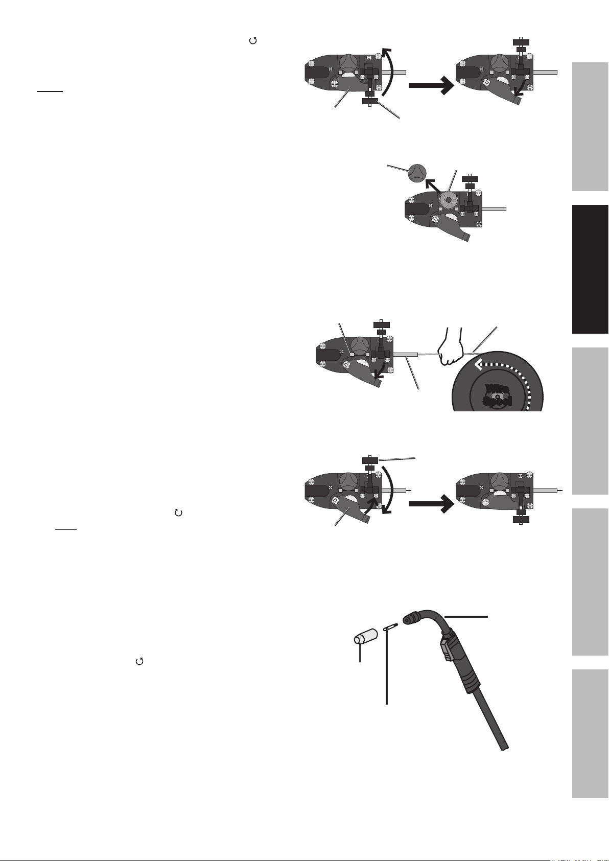
6. Turn the Feed Tensioner counterclockwise to
loosen it enough to pull it up, releasing tension.
Swing the Feed Swing Arm out.
Note: Do not loosen the Feed Tensioner
too much, or it will come apart.
7. Loosen and remove the Feed Knob. Compare
the wire diameter marked on the Wire Spool with
the stamped number on the top of the Feed Roller.
The Roller’s groove size must be compatible with
the wire diameter. Flip the Feed Roller as needed
and confirm that the number facing up is the same
as the wire diameter on the Spool.
Replace and secure the Feed Knob.
.030″
Feed Swing
Arm
Feed
Knob
Feed
Tensioner
Feed
Roller
.030″
.030″
SAFETYMAINTENANCE BASIC WELDINGWELDING TIPS SETUP
IMPORTANT:
Securely hold onto the end of the welding wire and
keep tension on it during the following steps.
If this is not done, the welding wire will unravel
and create a tangled “bird’s nest”, wasting wire.
8. Cut off all bent and crimped wire.
Make sure that the cut end has no burrs
or sharp edges; cut again if needed.
9. Keep tension on the wire and guide at least
12 inches of wire into the Wire Liners.
10. Swing the Feed Swing Arm closed, and swing
the Feed Tensioner across the tip of the Arm, to
latch it. Make sure the Welding Wire is resting in
the top groove of the Feed Roller, then turn the
Feed Tensioner clockwise a couple of turns.
After the wire is held by the Feed
Tensioner, you may release it.
Wire
Liner
.030″
Feed Swing
Arm
HOLD WIRE
SECURELY
welding
wire
.030″
leader
wire liner
Wire
Spool
Feed
Tensioner
.030″
11. Pull the Nozzle to remove it.
12. Turn the Contact Tip
counterclockwise and remove.
13. Lay the Gun Cable out in a straight line so that the
wire moves through it easily. Leave the cover open,
so that the feed mechanism can be observed.
Gun
Nozzle
Contact
Tip
Page 9For technical questions, please call 1-800-444-3353.Item 68887
 Loading...