

Page 1
Getting Started
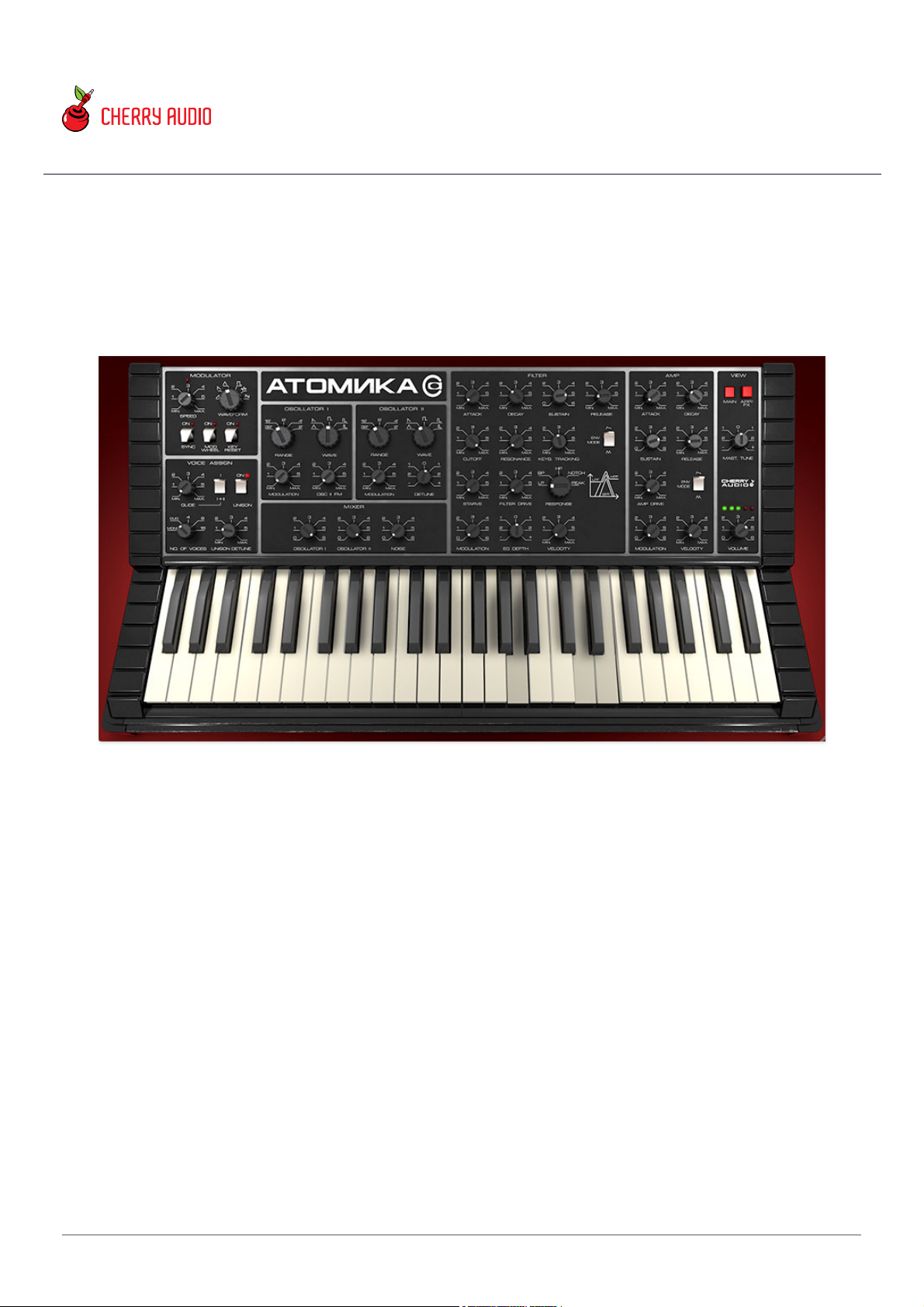
Atomika is an emulation of the Soviet Polivoks synthesizer, manufactured at
the Formanta Radio Factory between 1982 and 1990, and designed by
Vladimir Kuzmin. At first glance, it appears to be a typical compact analog
synthesizer (albeit, with cold-war radio design cues, courtesy of Mr. Kuzmin's
wife Olimpiada), but it includes a number of unique features that have made
it highly desirable amongst synthesizer cognoscenti.
First and foremost is Polivoks's unique filter. Instead of the likely-unavailablein-the-Soviet-Union transconductance amplifiers seen in 12 dB/octave statevariable filter designs of the era, Kuzmin figured out a way to completely
misuse programmable op-amps that were never intended for use in audio
filter circuits to perform the same function, somewhat accidentally resulting
in a rich and raunchy filter tonality. This was in the same ballpark as the
(in)famous Korg MS-series filter, but with a sonic signature all its own. Up to
Atomika Synthesizer User Guide
Last updated 2025.05.01
Cherry Audio Atomika Synthesizer User Guide - 1
Page 2

this point, we've never seen a virtual instrument that could properly
reproduce the Polivoks filter tone, but our frequent collaborator Mark Barton
(MRB) was able to nail it through a combination of analysis, breadboarding,
and coding wizardry! Along the way, Mark discovered other methods to
expand upon the unique Polivoks filter circuit, by adding unique
Starve, Filter
Drive
, and
Amp Drive
controls that further extend its twisted palette, often in
radical ways.
The original instrument also included a duophonic mode, similar to those
seen in ARP synthesizers of the era, where the lowest and highest played
notes would be assigned to each oscillator. Frankly, these worked pretty
inconsistently, so Atomika trades this for a proper poly keyboard mode with
up to 16-voice polyphony, as well as a mono mode with unison and detune
for superior flexibility.
We also took the liberty of adding an arpeggiator and effects page, including
a full-function arpeggiator and phasor, flange/chorus, echo, and reverb
effects, plus a bonus FX Modulator LFO. In the spirit of Polivoks's bold and
eccentric character, the FX Modulator enables radical (and synchronized)
modulation of key effects parameters for radical and deranged sound
transformations.
We hope you'll enjoy exploring Atomika's vast, madcap sonic landscape!
Manual Layout
This manual will detail each section of Atomika; the order of the chapters
follows the signal flow (as opposed to the physical layout of the front panel).
Hey, I just fired up Atomika in standalone
mode and it doesn't work! What the hey?!?
If you just launched the standalone app version of Atomika (i.e., not a plugin
running in DAW software) and nothing is happening when you play keys on
your MIDI/USB controller, it's almost certainly because Atomika doesn't know
what controller you're using. This is super easy to fix:
Click the
Settings
gear icon in the purple menu strip at the top of
the screen.
Cherry Audio Atomika Synthesizer User Guide - 2
Page 3
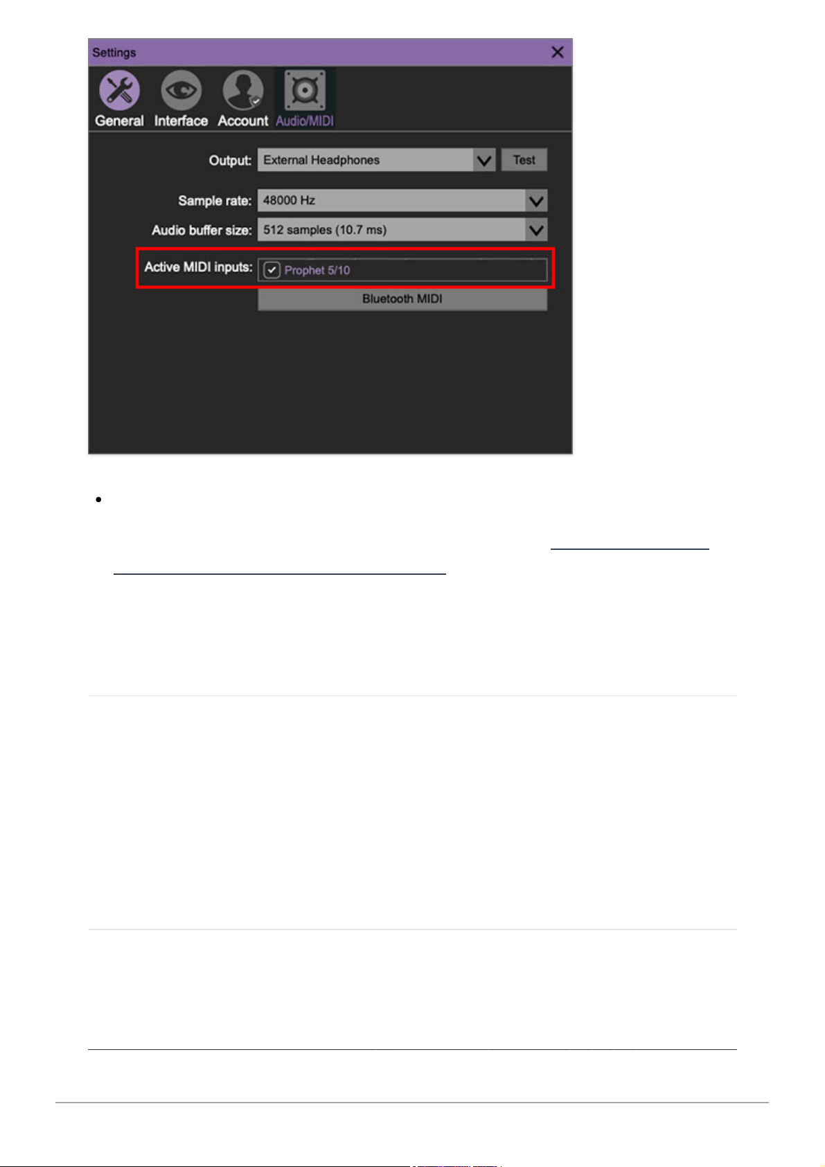
Click the
Audio/MIDI tab
at the top. Now look for the name of your
MIDI/USB controller next to
Active MIDI inputs
and check the box next to
it. If you don't see the name of your controller here, maybe this playing
with synthesizers thing just isn't for you...check that the controller is
properly plugged in and powered up. If that doesn't work feel free to
contact our support below.
Technical Assistance
Cherry Audio's unique online store and automatic updating should make
operation a smooth experience, but if you run into any issues or have
questions, you can discuss issues online at the Cherry Audio forums at:
https://forums.cherryaudio.com/
... or you can open a support ticket with our friendly tech support staff at:
https://cherryaudio.kayako.com/
Acknowledgements
We'd like to extend a huge thank you to Andrew Ru for invaluable assistance
with the front panel native panel translation.
Cherry Audio Atomika Synthesizer User Guide - 3
Page 4
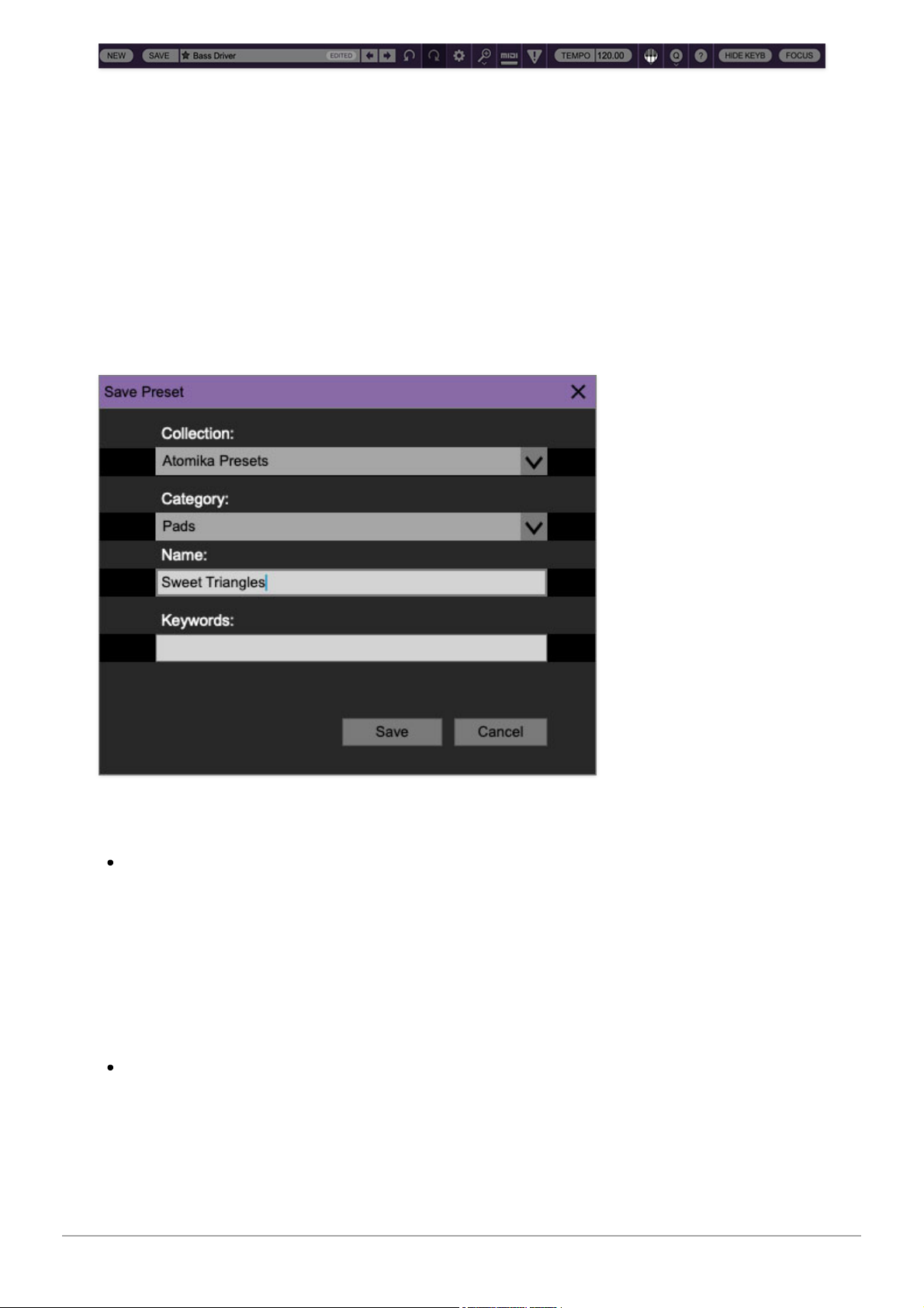
The purple strip at the top of the Atomika interface is where you’ll load, save,
and create sound presets. It also contains utility functions such as undo/redo,
UI zoom and
Focus
controls, under-the-hood settings, and more. Let’s go over
them:
New- Opens a new blank patch preset. If an unsaved patch is currently open
or you’ve modified an existing saved patch, a dialog asks if you’d like to save
the patch in its current state. This greatly reduces the possibility of losing an
edited unsaved patch.
Save- Use this to save patches. There are a couple of levels of hierarchy:
Collection- This is the top level of organization, and contains entire
“sets” of presets. The
Atomika Presets
are the main included collection.
We also include a
User Presets Collection
for storing your own presets, but
you’re free to create your own collections. To create a new collections,
click in the
Collection
text field (where it says
User Presets
above) and
type a name. User-created sounds can be freely saved to any collection;
we like to keep ‘em separated for organizational purposes.
Categories- Within each
Collection
are a number of sound categories. As
with collections, you’re free to create as many categories as you like. To
create a category, click in the
Category
text field of the
Save
dialog
window and type a new category name.
Cherry Audio Atomika Synthesizer User Guide - 4
Page 5
Patch- A patch is an individual sound. To save a patch, simply type the
name in the
Name
field and click
Save
.
Keywords- You can add descriptive words such as “bass,” “lead,”
“spaceship,” etc., to patches to make them appear when terms are typed
in the
Search
field. Use commas to separate multiple keyword entries.
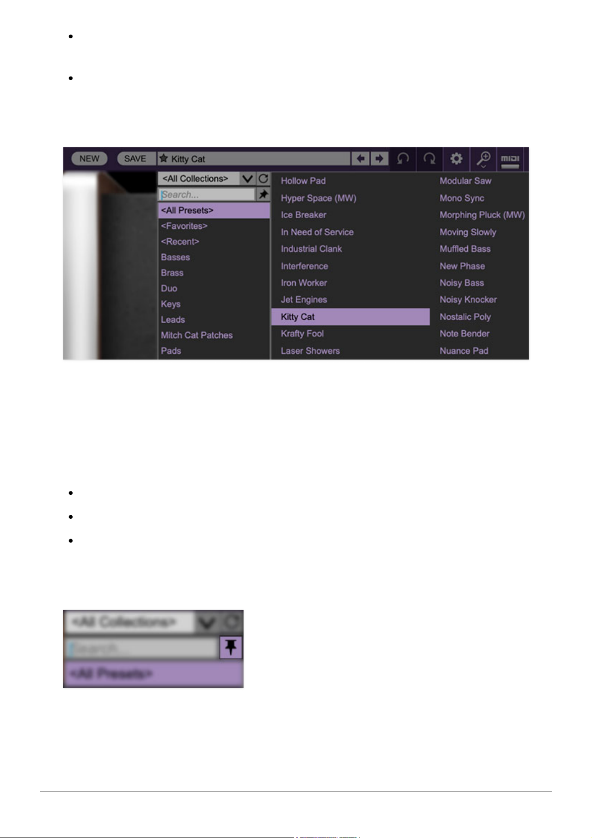
Browsing Patches- Patches can be browsed by clicking the <
Select Preset
>
field. To select a preset collection, click in the area that says <
All
Collections
> or on the downward-facing arrow next to it.
Clicking on the left-side categories narrows down which patches are
displayed.
<All Presets> will show presets from all collections and categories.
<Recent> displays recently used presets.
Refresh- This is the circular arrow button to the right of the downward
arrow; clicking this checks the Cherry Audio server for new or updated
presets.
Pin- Clicking the push-pin icon locks the patch selection list open, allowing
fast and easy browsing and auditioning of patches. Click the icon again to
Cherry Audio Atomika Synthesizer User Guide - 5
Page 6

disable pin mode. when in pin mode, the up and down arrow keys can be
used to select patches.
Preset Step Back/Forward horizontal arrows- These step to the previous
or next preset. macOS [⌘+left/right arrow key] or Windows [CTRL+left/right
arrow key] will navigate through presets back and forth in the currently
selected collection/category.
Undo/Redo circular arrows- These undo or redo the last action. It
remembers many steps, so if you really mucked something up, keep on
clickin'...
Settings- This is where user preferences for user interface, audio interfaces,
user account, and more are configured. See the Settings section for full
information.
Importing Presets with drag-and-drop
Presets can be imported singly or en masse (as a single compressed ZIP file)
simply by dragging and dropping from the desktop anywhere on the user
interface.
If a single .*preset file is dragged and dropped, the sound is immediately
loaded and the standard
Save Preset
dialog appears; this lets you save the
sound to the instrument's preset browser. Note that you don't have to save
the sound to preset browser; if you just want to hear and play the sound,
click the
Cancel
button in the
Save Preset
dialog - the sound will still be
loaded.
Compressed zip files containing multiple sounds can also be drag and
dropped onto the UI. This works the same as with single sounds, but instead
of the
Save Preset
dialog, you'll see the
Import Preset Collection
dialog. The
presets will be added as a new collection and available in the categories for
which they were tagged.
Cherry Audio Atomika Synthesizer User Guide - 6
Page 7
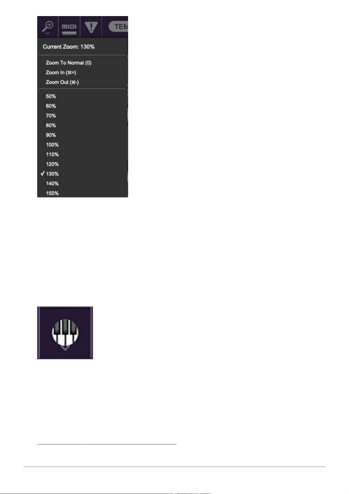
Zoom Magnifying Glass- Click to resize the Atomika interface. Selecting
100%
returns the user interface to native size.
MIDI Tab- Opens the MIDI controllers tab for configuring internal and
hardware MIDI controls. See the MIDI Controllers Setup and MIDI Tab
section for full information.
! (MIDI Panic) - Click to send an all-notes-off message in case of, "why
won't this thing stop making noise?!?" stuck-note incidents.
QWERTY Musical Typing Keyboard- Opens an onscreen keyboard allowing
a standard QWERTY computer keyboard to be used for playing music notes.
For more information, see QWERTY Musical Typing Keyboard (MTK)
section.
Cherry Audio Atomika Synthesizer User Guide - 7
Page 8
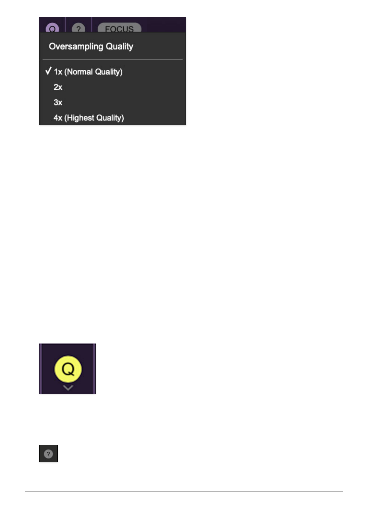
Q Oversampling Quality - The Q button sets Atomika's internal
oversampling rate; the higher the setting, the better audio fidelity will be,
with the caveat that more computer processing power will be required.
Internal processing can be set to 1x (same rate as the current sample rate of
the host DAW or in the
Settings>Audio/MIDI
window for the standalone
version) or to 2x, 3x, or 4x the current sample rate. The sample rate is
downsampled at the instrument output stage to match the current host
sample rate.
For example, if the current DAW/instrument sample rate setting is 48 kHz,
and oversampling is set to 2x, Atomika's internal processing runs at 96 kHz,
and is then reduced back to 48 kHz at the output stage.
If the current DAW/instrument sample rate setting is 192 kHz and
oversampling is set to 4x, Atomika's internal processing will run at 768 kHz,
and you will very briefly hear the most ameeeezing synthesizer sound quality
ever experienced by mankind before your computer instantaneously
explodes in a fiery, white-hot supernova blaze. Ok, maybe not.
When oversampling is set to any multiple greater than 1x, the Q button
glows yellow.
Cherry Audio Atomika Synthesizer User Guide - 8
Page 9
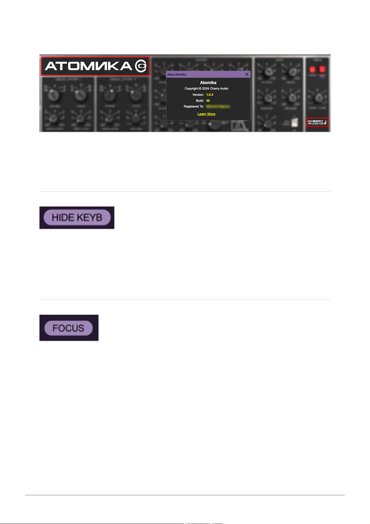
Help- Clicking this launches your web browser and opens this help
document. (Confusing circular logic thing there, huh?)
Atomika and Cherry Audio badges- Clicking these displays “about”
information, and shows the version number and current registered user ID.
Hide/Show Keyboard
This lets you hide or display Atomika's onscreen keyboard. Hiding the
keyboard reduces the overall plug-in window dimensions and is useful if
screen space is at a premium.
Focus
If you're using a tiny laptop, the user interface can potentially be hard to see.
With this in mind, the
Focus
button conveniently blows up Atomika's view to
roughly twice its normal size within the current window size. Unlike the
Zoom
"magnifying glass" function,
Focus
doesn't affect the current window size. By
default, the patch panel section fills the current window, but the view can be
scrolled vertically and horizontally with a mouse wheel, track pad, or Apple
Mighty Mouse finger-scrolling. Or if you're the last person on earth still using
a single-button mouse, scroll bars will appear at the window edges when in
Focus
mode.
Cherry Audio Atomika Synthesizer User Guide - 9
Page 10
Using
Focus
mode couldn't be easier - just click the
Focus
button the top
menu bar. To return to standard view, click
Reset
.
Preset List Right-Click Functions
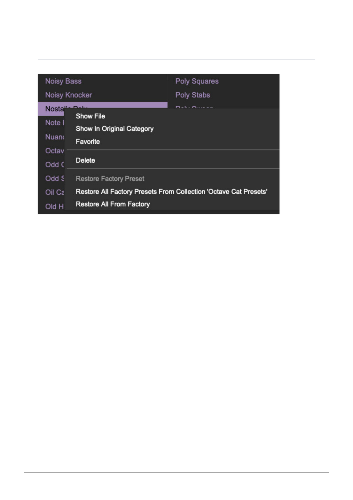
Show File- This displays the selected preset in the Mac or Windows folder
containing it. This is useful for backing up or sending a preset file to another
user.
Show In Original Category- Selects the preset within its category, i.e. the
category will highlight in the left preset menu. The
Show In Original Category
command only displays if the preset was selected within the <
All Presets
>,
<
Favorites
>, or <
Recent
> categories.
Favorites- Favorited presets will show in when the <
Favorites
> category is
selected. A star will display next to the preset name. Right-click on the preset
and reselect
Favorite
to un-favorite it. (Or just ghost it if you don't do the
confrontation thing.)
Delete- Deletes the selected preset.
Restore Factory Preset- If one of the factory (i.e. not user) patches is
edited and saved, selecting this command restores the patch to its unaltered
"factory" setting. This menu will be grayed-out for user bank patches.
Restore All Factory Presets From 'Atomika Presets'- If any patches
from the "factory" Atomika bank are edited and saved, selecting this
command restores
all
of them to their unaltered "factory" setting.
Cherry Audio Atomika Synthesizer User Guide - 10
Page 11

Restore All From Factory- If any patches from the "factory" banks are
edited and saved, selecting this command restores
all
of them to their
unaltered "factory" setting. At the time of writing, the Atomika bank
mentioned above is the only factory bank, so this function and the
Restore
All Factory Presets From 'Atomika Presets'
above have the same effect.
Cherry Audio Atomika Synthesizer User Guide - 11
Page 12
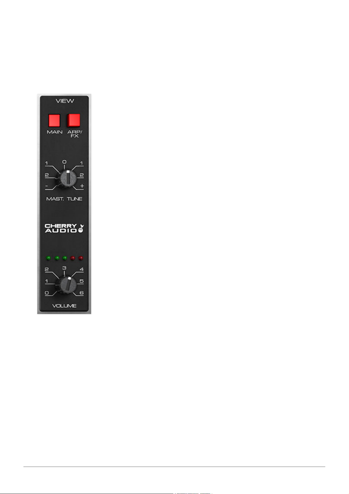
The original Polivoks panel was pretty straightforward. In addition to the
original controls, Cherry Audio Atomika adds a full effects section with a
dedicated modulator, plus a full-featured arpeggiator. In order to
accommodate all necessary additional controls, we added a "page two" view.
The current UI page is selected in the
View
section at the right of the
instrument.
Main / Arp/FX- Use these buttons to select between
Atomika's two UI pages. The
Main
page closely resembles
the original instrument with controls for oscillators, filter,
amp, modulator, and voice assignment, and glide. The
Arp/FX
page has all the controls for (you guessed it), the
arpeggiator, effects, and the dedicated effects modulator
section. Note that control settings are not affected
when switching between views.
Master Tune- Sets the overall tuning for the entire
instrument up or down by two semitones.
Cherry Audio logo- Clicking this displays “about”
information, and shows the version number and current
registered user ID.
Volume- Sets overall volume for the entire instrument.
The five red LED's above the Volume knob display overall
level. Unlike other Atomika controls that can cause it to
desirably distort like crazy, we strongly recommend
keeping this out of the red, otherwise you'll hear digital
distortion of the yucky variety.
Cherry Audio Atomika Synthesizer User Guide - 12
Page 13
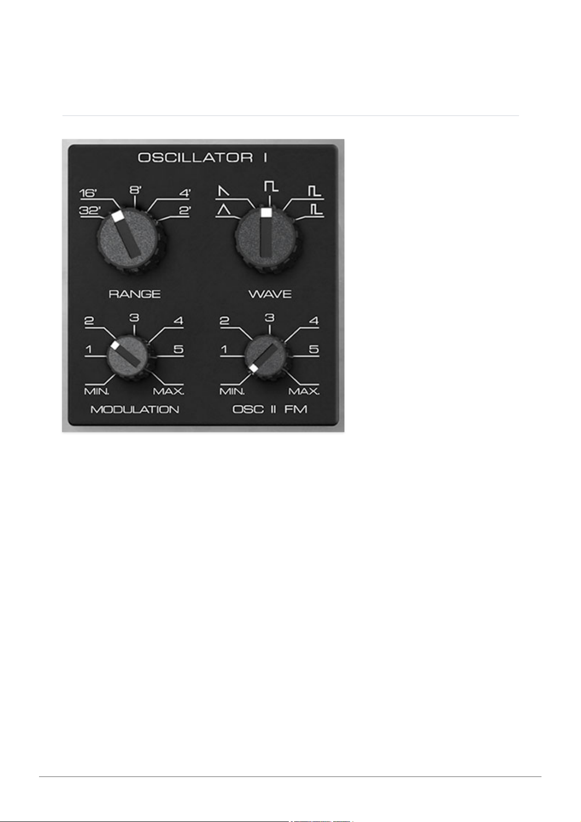
Atomika includes two oscillators. Their controls are mostly similar, but
different enough that we'll go over each individually, because online-doc ink
is free!
Oscillator I
Range- Coarsely sets the signal generator pitch range in octaves. These are
at standard organ footage settings of
32', 16', 8', 4'
, and 2'.
Wave- This sets the basic oscillator waveform, including triangle, ramp,
square, wide pulse, or narrow pulse.
Modulation- Sets the amount of modulation received from the Modulator in
the upper-left corner. This is affected by the
Mod Wheel
switch in the
Modulator section; for more info see the Modulator section.
Osc II FM- Sets the amount of modulation received from
Oscillator II
. Unlike
typical low-frequency oscillator modulation (like the kind produced by the
Modulator
section) where the modulation sweep is clearly audible (imagine
vibrato or tremolo), when pitch is modulated with an audio-range range
oscillator, the modulation sweep is far too fast to be heard. This results in
clangorous metallic sounds that can resemble ring modulation, bell tones, or
the fabulous Yamaha FM digital synths of the 80s.
Cherry Audio Atomika Synthesizer User Guide - 13
Page 14
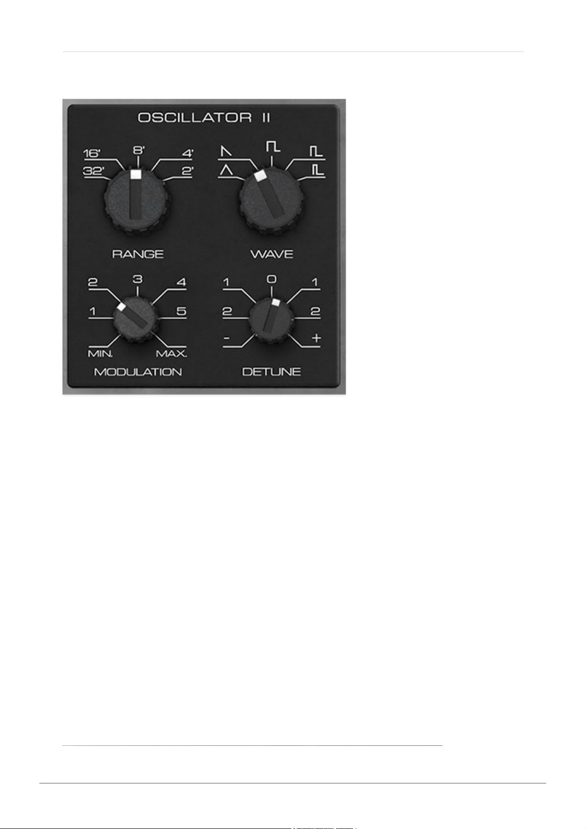
Oscillator II
Oscillator II
is largely the same as
Oscillator I
with a few minor difference.
Range- Coarsely sets the signal generator pitch range in octaves. These are
at standard organ footage settings of
32', 16', 8', 4'
, and 2'.
Wave- This sets the basic oscillator waveform, including triangle, sawtooth,
square, wide pulse, or narrow pulse.
Modulation- Sets the amount of modulation received from the Modulator in
the upper-left corner. This is affected by the
Mod Wheel
switch in the
Modulator section; for more info see the Modulator section.
Detune- This can be used to fatten dual oscillator patches by detuning a
small amount, or for "building-in" musical intervals. Its range is up or down a
fifth.
Range- Coarsely sets the signal generator pitch range in octaves. These are
at standard organ footage settings of
32', 16', 8', 4'
, and 2'.
Cherry Audio Atomika Synthesizer User Guide - 14
Page 15
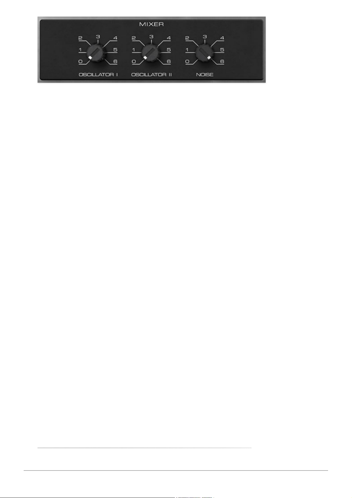
The Mixer section combines signals prior to the filter section.
Oscillator I/Oscillator II level- Sets the amplitude of each oscillator. Unlike
most analog synths, these can really make a difference in the overall sound,
particularly in conjunction with the filter
Resonance, Filter Drive
, and
Starve
controls and the Amp section
Amp Drive
control. We definitely recommend
experimenting with oscillator levels if you're getting out there the
aforementioned filter and amp controls!
Noise - Sets the volume level of Atomika's white noise generator. For those
of you hoisting clipboards, white noise is a random signal wherein all
frequencies across the frequency spectrum are represented equally (and for
those of you who aren't... it's a loud hissing sound).
Cherry Audio Atomika Synthesizer User Guide - 15
Page 16
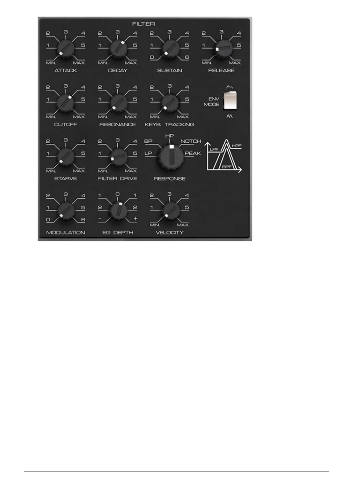
The original Polivoks filter is unquestionably its most unique feature - it
boasts a truly unique, gnarly distorted tone. Although this certainly wasn't
the intended outcome, the Polivoks filter is loved by many synthesists. Over
the years, there have been numerous copies of its circuit in the hardware
modular synthesis world, but up until now, it hasn't been emulated in the
virtual synthesizer world.
The basic design was intended to emulate the 12dB/oct slope state-variable
filters seen in Oberheim synths of the 70s and 80s. These are great-sounding
filters and highly flexible as a result of their multiple modes (more on this
later). Filters of this type made use of a still-relatively-new component called
an "operational transconductance amplifier" or OTA. We'll assume that a lack
of availability of fancy-pants OTAs in the Soviet Union during the 80s is what
drove designer Vladimir Kuzmin to forego the OTA and instead make use of
something called a "programmable op-amp" in its place. These were never
intended for a variable filter application, but alas, Vladimir Kuzmin figured
out a way to use it in such a manner, and thus, the raunchy Polivoks filter
was born.
Cherry Audio Atomika Synthesizer User Guide - 16
Page 17

Also, we'd be remiss not to mention the nifty
Envelope Generator Mode
switch. This puts the Filter's ADSR envelope in looping mode, which
essentially gains you an LFO, and it lets you create unique mod waveshapes.
(The Amp section has this capability too, hooray!)
The Original Polivoks Filter vs. Atomika's
Super-Duper New and Improved Filter
The controls for the original Polivoks filter are straightforward and similar to
what you'd see in any garden-variety analog synth (cutoff frequency,
resonance, envelope controls and depth, etc.). It does however have
switchable lowpass and bandpass modes. However, Cherry Audio's Atomika
goes WAY beyond, including the aforementioned lowpass and bandpass
modes, plus highpass, notch, and peak modes. (see the
Response
control
section below for the nitty gritty on exactly what each of these do) As you
might imagine, these extra modes offer far more sounds than the original.
Furthermore, due to its unique design, our mad scientist DSP doctor Mark
Barton discovered a few eccentric circuit behaviors along the way. Realizing
these sounded pretty neat, these were incorporated into the design with the
Starve
and
Filter Drive
controls (as well as the
Amp Drive
knob in the Amp
section). This all adds to up to even more of the idiosyncratic filter sound of
Atomika.
Filter Envelope Controls
The dedicated ADSR filter envelope controls are incorporated into the Filter
section. The filter envelope is hardwired to filter cutoff frequency, with its
depth controlled via the
EG Depth
knob. If you're not familiar with the
operation of an ADSR envelope generator, please see
How An ADSR
Envelope Generator Works
in the Amp section.
Attack- Defines the length of time for voltage to rise from minimum to
maximum voltage when a key is played.
Decay- Defines the length of time for voltage to fall from the attack stage
peak to sustain stage setting.
Sustain- Sets the voltage level following attack and decay phases while a
note is held.
Release- Defines the length of time for voltage to fall from sustain level to
minimum voltage when a key is released.
Cherry Audio Atomika Synthesizer User Guide - 17
Page 18

Cutoff- Sets the frequency where frequency attenuation begins. Its effect is
dependent upon the currently selected filter
Response
setting.
Resonance- Emphasizes sound energy at and around the cutoff frequency
by adding feedback from the filter's output back to its input. This is useful for
creating commonly heard synth "wah" tones, especially when the cutoff
frequency is modulated with an envelope generator or one of the LFO's.
Atomika's resonance circuit can result in some squelching and
screaming at higher settings, so be cautious with volume when
cranking the Resonance knob.
That said, because of its propensity to
distort, it usually doesn't get too crazy, because the distortion tends to act
like a natural limiter. But hey, we gotta warn people, because who knows
what folks will get up to (then blame us on momsbasementsynthdweller.com
when everything goes awry because of the
Resonance
knob).
Keyboard Tracking- Causes the cutoff frequency to increase as ascending
notes are played on the keyboard. The idea behind this that some (or all) of
the keyboard CV signal is added to the cutoff frequency in order to offset the
rising pitches of notes in order to maintain the brightness of notes as higher
pitches are played. (If the filter cutoff frequency remained constant, lower
notes would appear to sound brighter than higher ones.)
The original Polivoks did not include a keyboard tracking control - the
tracking CV was "built-in" and set to a preset value. We decided to add the
Keyboard Tracking
control mainly to facilitate cranking the
Resonance
knob
and "playing" the resulting pitched resonant notes across the keyboard.
Envelope Generator Mode- In the up position, the Filter envelope functions
as a standard ADSR (attack/decay/sustain/release) envelope generator. In
the down position, the Filter envelope is set to looping mode. This effectively
converts the envelope generator to an LFO, with its controls affecting the
modulation waveshape. The
Attack
and
Decay
controls are most effective
here; be sure to set
Sustain
to a low value or the envelope won't loop at all.
Starve- This parameter is unique to the filter design, resulting from the
aforementioned programmable-op-amp-incorrectly-used-as-filter
architecture. If the settings are correct, the filter can take on an oscillating
"bubbly" sound, for lack of better wording. Try
Cutoff
between 1 and 2,
Resonance
at max, and
Starve
between 5 and 6 as a starting point.
Filter Drive- This is not a standard filter overdrive/breakup control, but like
Starve, is unique to how the Polivoks filter resonance circuit interacts with
Cherry Audio Atomika Synthesizer User Guide - 18
Page 19

the power supply rails. The technical details aren't important; what you
should know is that it tends to work best with
Resonance
at high settings,
and the
Filter Drive
knob at very low or very high settings - all manner of
radical distorted noises happen when Resonance is cranked and
Filter Drive
is set to 0!
Response- Selects the overall filter curves. The jaunty graphic to the right of
the
Response
selector shows a rough visual approximation of the lowpass,
bandpass, and highpass response curves, with vertical representing
amplitude, and horizontal representing frequency.
LP (Lowpass)- Allows frequencies belowthe cutoff frequency to pass, but
blocks frequencies abovethe cutoff frequency with an 12 dB/oct slope.
BP (Bandpass)- Allows a band of frequencies in the vicinity ofthe cutoff
frequency to pass, with a 6 dB/oct slope on either side of the peak.
HP (Highpass)- Allows frequencies abovethe cutoff frequency to pass,
but blocks frequencies below the cutoff frequency with a 12 dB/oct slope.
Because they dramatically remove low frequencies, the highpass setting
is useful for nasally tones with exaggerated high frequencies.
Notch- Removes a band of frequencies close to the cutoff frequency and
allows all other frequencies to pass. The notch width varies dependent on
the current
Resonance
setting, with low
Resonance
resulting in the widest
Notch width. Notch filters are useful for pseudo-phaser effects when their
cutoff frequency is swept, but hey, that's notch your problem, right? (
"And
the award for the most Daddest User Manual Joke goes to..."
)
Peak- A pronounced resonant peak at the cutoff frequency, and no rolloff
on either side of the peak frequency. Incidentally, the
Peak
setting excels
at really saturated, aggressive sounds when the
Resonance
knob is
cranked.
By the way, similar to the one on the original instrument, that fanciful little
graphic next to the
Response
control gives a rough visual indication of the
lowpass, bandpass, and highpass filter behaviors. The vertical axis
represents amplitude; the horizontal axis represents frequency.
Modulation- Sets the amount of mod depth from the Modulator section at
top left. This is affected by the
Mod Wheel
switch in the Modulator section;
for more info see the Modulator section.
EG Depth- Sets the amount of mod depth from the ADSR Filter envelope
generator controls at the top of the filter section.
Cherry Audio Atomika Synthesizer User Guide - 19
Page 20

Velocity- Sets the how much the cutoff frequency is affected by keyboard
velocity. To use the
Velocity
control, make sure the
EG Depth
knob is at a
non-zero setting (we recommend starting full up). It works slightly
"backwards" - increasing the the
Velocity
amount increases control range, so
the cutoff frequency appears to decrease as the
Velocity
knob is increased.
Cherry Audio Atomika Synthesizer User Guide - 20
Page 21
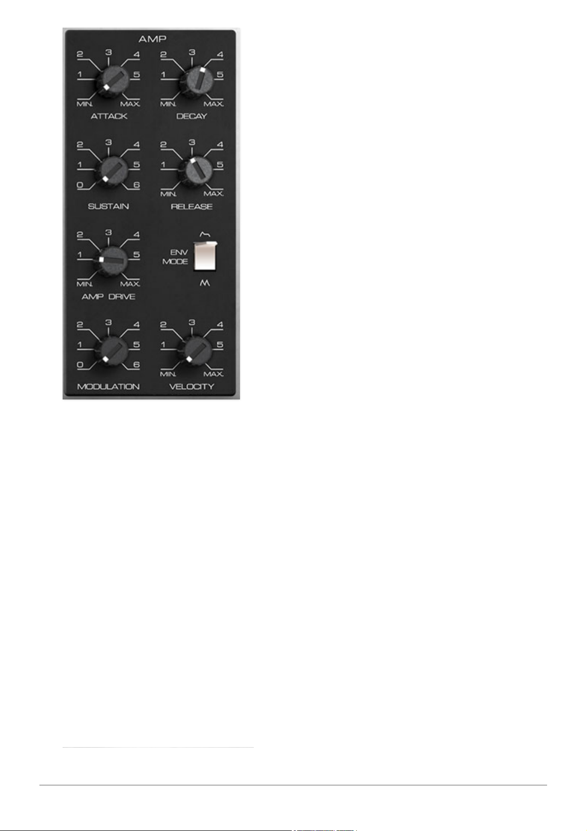
The Amp section controls overall amplitude
(volume); this is mainly configured using
the ADSR envelope generator, but controls
for modulation amount and note velocity
are also found here. .
Attack- Defines the length of time for
voltage to rise from minimum to maximum
voltage when a key is played.
Decay- Defines the length of time for
voltage to fall from the attack stage peak
to sustain stage setting.
Sustain- Sets the voltage level following
attack and decay phases while a note is
held.
Release- Defines the length of time for
voltage to fall from sustain level to
minimum voltage when a key is released.
Amp Drive- This sets the amount of drive
into the amp section, and as you might
imagine, it's used to overdrive the amp
section. Hooray for distortion!
Envelope Generator Mode- This is the same as the Filter section Envelope
Generator Mode switch - in the up position, the Amp envelope functions as a
standard ADSR (attack/decay/sustain/release) envelope generator. In the
down position, the Amp envelope is set to looping mode. This effectively
converts the envelope generator to an LFO, with its controls affecting the
modulation waveshape. The
Attack
and
Decay
controls are most effective
here; be sure to set
Sustain
to a low value or the envelope won't loop at all.
Modulation- Sets the amount of mod depth from the Modulator section at
top left. This is affected by the
Mod Wheel
switch in the Modulator section;
for more info see the Modulator section.
Velocity- Sets the how much note amplitudes are affected by keyboard
velocity. It works slightly "backwards" - increasing the the
Velocity
amount
increases the velocity range, so note amplitude appears to decrease as the
Velocity
knob is increased (whack a key hard and it'll make sense).
Cherry Audio Atomika Synthesizer User Guide - 21
Page 22
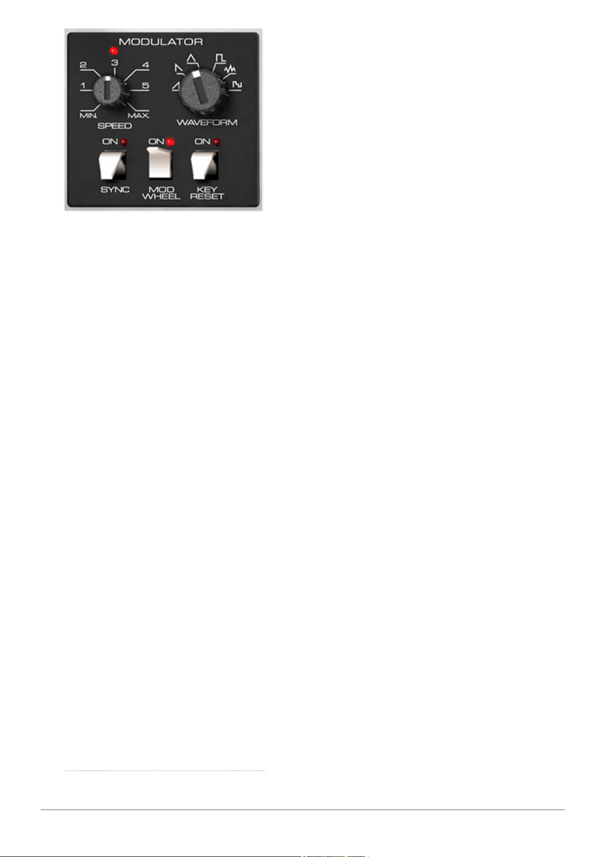
The Modulator section is a low-frequency
oscillator that generates sub-audio range
signals intended for modulation
purposes. We've expanded on the
original instrument in a couple of useful
ways, including multiple modulation
waveforms and tempo sync.
Speed- The Speed knob sets the
Modulator speed, from 0.01 to 20 Hz
(with
Sync
switch off) or from 8 beats up to 1/64th note triplets (
Sync
switch
on). The LED above the
Speed
slider flashes at the current modulation rate.
Waveform- Selects the repeating pattern of the Modulator. Available
waveforms are ramp, sawtooth, triangle, square, noise, and random (aka,
sample & hold).
Sync- When the
Sync
switch is enabled, Modulator speed will lock to host
tempo when using Atomika within DAW software, or to the current tempo in
the top menu bar when using the standalone version.
Mod Wheel- This is a really handy, but potentially confusing feature, so
don’t skim this section. If the switch is in the Off position, the Modulator is
always “on.” Its effects will be immediately audible by moving the Modulator
knobs in the Oscillator, Filter, and Amp sections. Clicking to the On position
enables control of Modulator depth with an external keyboard controller mod
wheel. If the mod wheel is all the way off, Modulator depth is zero. This
makes setting up a mod wheel to add vibrato or wah effects simple.If it
seems like the Modulator isn't working, check if the
Mod Wheel
switch is on.
Key Reset- Enabling
Key Reset
restarts the Modulator cycle monophonically
if no notes are currently on and a new note is struck. If additional keys are
played, the Modulator won't restart until all keys are released. This may
seem counterintuitive, but it makes sense - imagine a polyphonic patch with
square wave modulation applied to Amp amplitude (Amp section
Modulation
knob up). If you played a chord, with each note struck at a (slightly) different
time, the Modulator would restart every time a note was played, which could
result in a rhythmic mess.
Cherry Audio Atomika Synthesizer User Guide - 22
Page 23
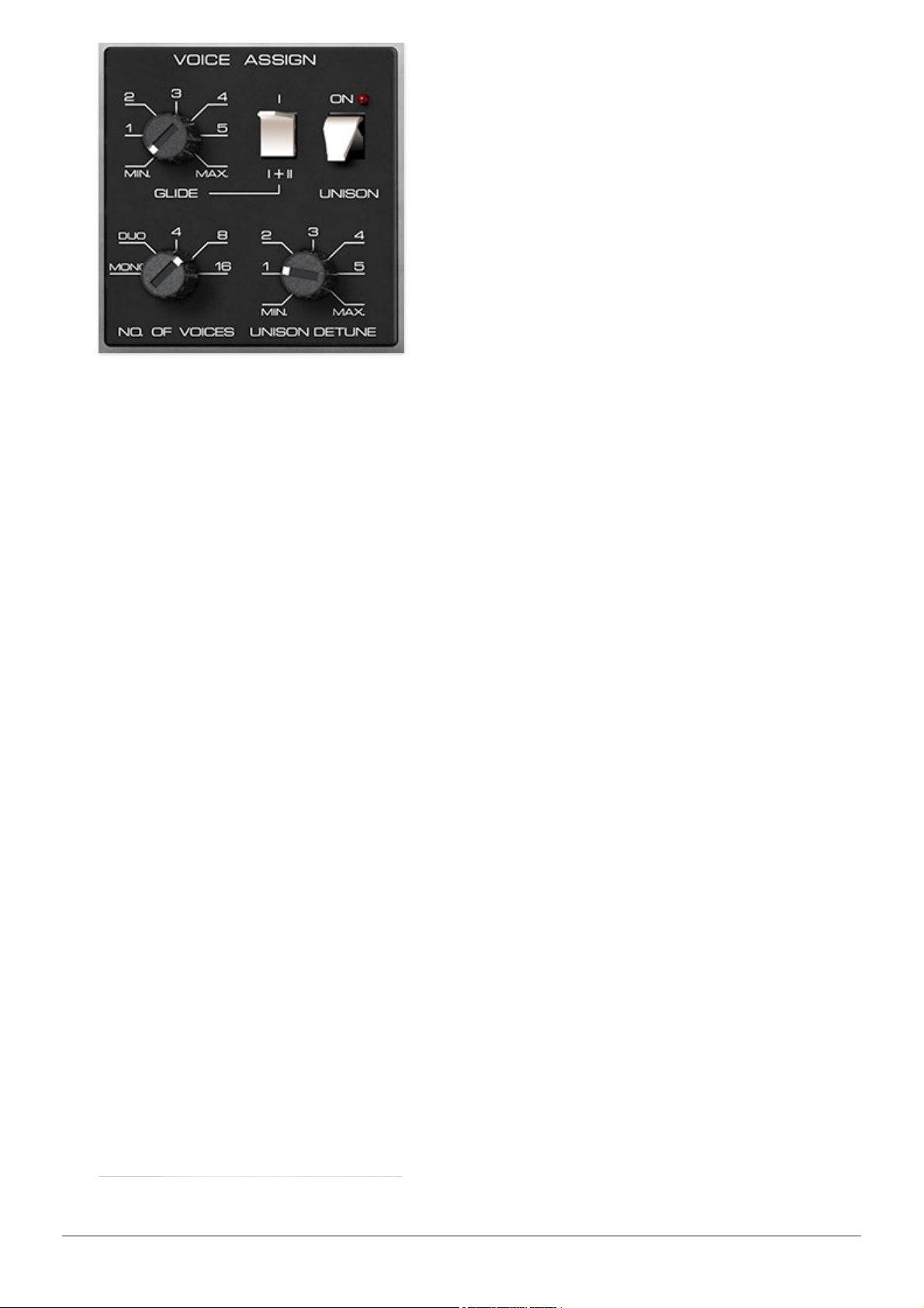
The Voice Assign section sets the
number of simultaneously playable
notes, as well as unison mode and glide
behavior.
Glide- The
Glide
knob causes notes to
slide smoothly from one pitch to the
next. Higher settings result in a slower
change of pitch.
Number of Voices- Sets the maximum
number of notes that can be played
polyphonically, from 2-16 voices per
layer. These are last-note priority - when the max number of notes is
reached, the oldest note will be stolen. With any modern computer, you
should be able to leave this at 16, but we've provided lower settings to save
processor cycles in case you're still holding on to that Pentium II machine
(and hop on them forums to let everyone what jerks those guys at Cherry
Audio are for not supporting your 15-year-old box of e-waste).
Unison- Unison stacks multiple voices according to the current
Number of
Voices
setting. The
Unison
switch is used in conjunction with the
Unison
Detune
knob which spreads out the tuning of the oscillators for fat sounds.
The keyboard will only play monophonically (i.e., one note at a time) when
the
Unison
switch is engaged.
Cherry Audio Atomika Synthesizer User Guide - 23
Page 24
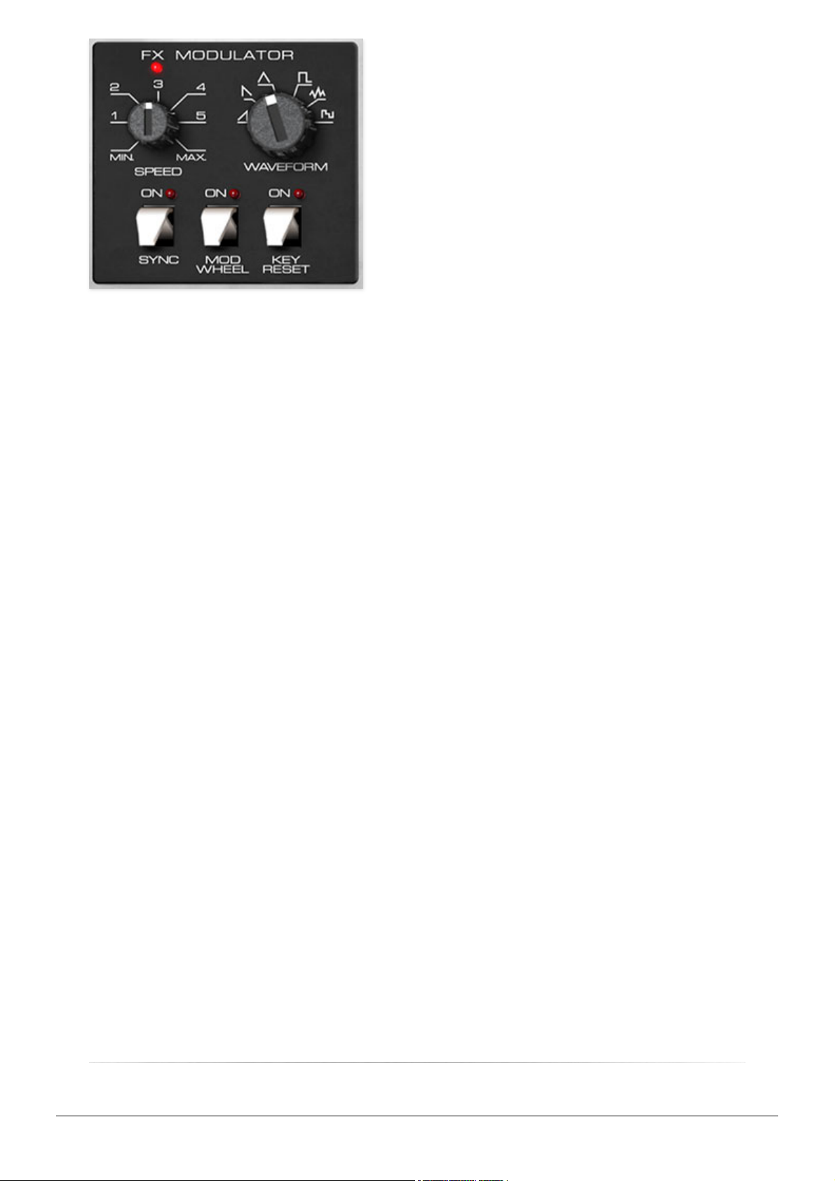
The FX Modulator section is a lowfrequency oscillator that generates subaudio range signals specifically for
modulating effects parameters. Though
it appears in the same location and
has similar controls, it operates
completely independently of the
Main page Modulator section.
Speed- The Speed knob sets the
Modulator speed, from 0.01 to 20 Hz
(with
Sync
switch off) or from 8 beats up to 1/64th note triplets (
Sync
switch
on). The LED above the
Speed
slider flashes at the current modulation rate.
Waveform- Selects the repeating pattern of the Modulator. Available
waveforms are ramp, sawtooth, triangle, square, noise, and random (aka,
sample & hold).
Sync- When the
Sync
switch is enabled, Modulator speed will lock to host
tempo when using Atomika within DAW software, or to the current tempo in
the top menu bar when using the standalone version.
Mod Wheel- This is a really handy, but potentially confusing feature, so
don’t skim this section. If the switch is in the Off position, the Modulator is
always “on.” Its effects will be immediately audible by moving the Modulator
knobs in the Phasor, Flange/Chorus, Echo, and Reverb sections. Clicking to
the On position enables control of Modulator depth with an external keyboard
controller mod wheel. If the mod wheel is all the way off, Modulator depth is
zero. This makes setting up a mod wheel to control effects modulation really
easy.If it seems like the FX Modulator isn't working, check if the
Mod
Wheel
switch is on.
Key Reset- Enabling
Key Reset
restarts the Modulator cycle monophonically
if no notes are currently on and a new note is struck. If additional keys are
played, the Modulator won't restart until all keys are released.
Cherry Audio Atomika Synthesizer User Guide - 24
Page 25
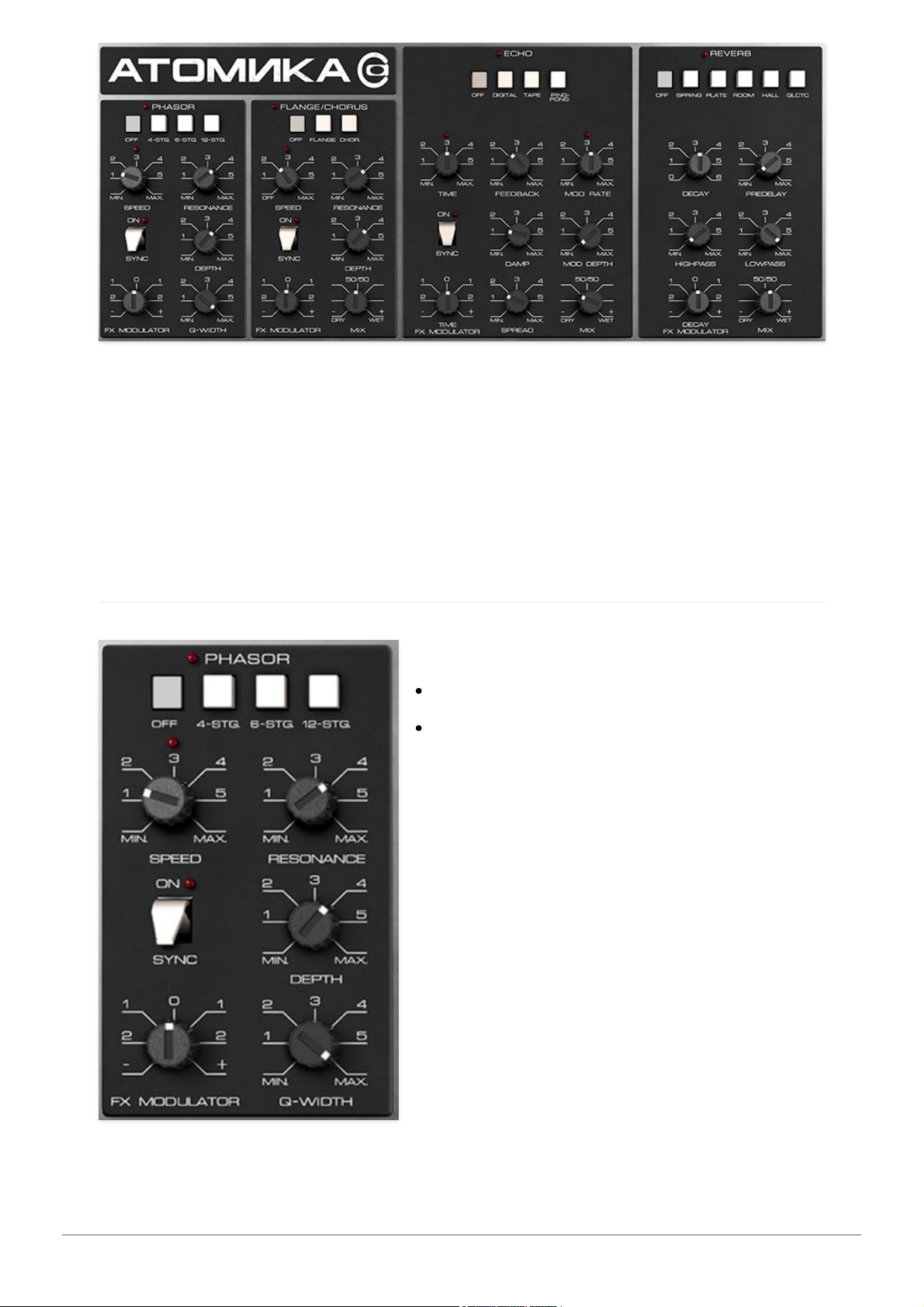
Atomika includes four simultaneous effects: Phasor, Flanger/Chorus, Echo,
and Reverb. These can be used in any combination. In case you're wondering
why we didn't include an overdrive or distortion effect, it's because Atomika's
Filter and Amp sections have so many colorful flavors of distortion, we
figured a dedicated effect would be superfluous (also, we were running out of
panel space and thought the FX Mod section was more useful!).
Phasor
Mode buttons-
Off- Phasor effect is disabled.
4/6/12 Stage setting- Atomika's phasor
includes up to 12 all-pass filter stages. As
a general rule, more stages = lusher
phase, but there are plenty of interesting
tones to be had using the lower stage
settings.
Speed- Sets the phasor's internal LFO
speed from 0.01 to 8 Hz.
Resonance- Increasing the amount of
Resonance
intensifies the phasing effect.
This is sometimes referred as "feedback"
in other phasor units.
Sync- The
Sync
slide switch locks the
rate of the Phasor's modulation LFO to the tempo in the top toolbar when
Cherry Audio Atomika Synthesizer User Guide - 25
Page 26
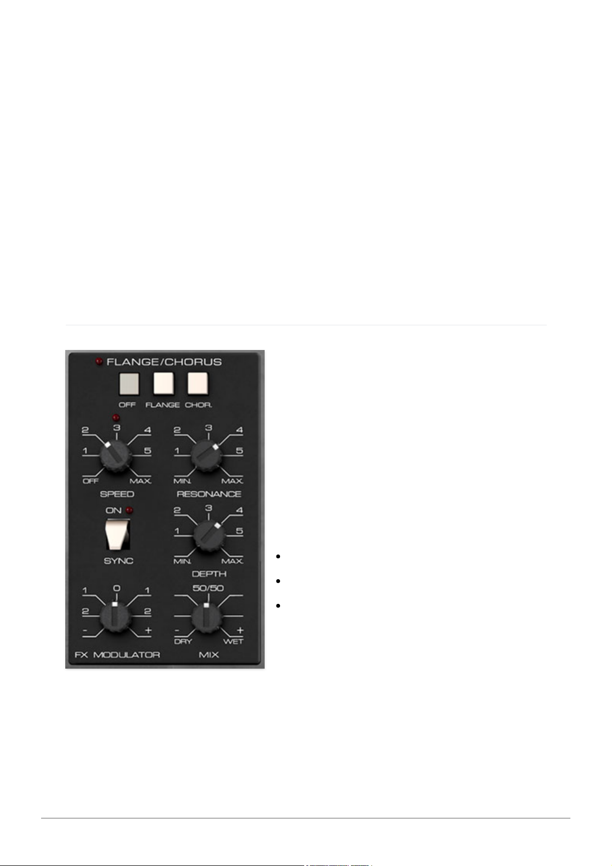
using the Atomika standalone version, or to the current project tempo when
the plug-in version is used in a DAW. When engaged, the
Speed
knob snaps
to note values ranging from 1/64th note triplet to 8 beats.
Depth- Sets the effect depth - essentially an amount control.
FX Modulator- Sets the amount of sweep mod from the FX Modulator
section in the top left corner. To disable the Phasor's dedicated LFO, set the
Depth
control to zero. This lets you use the FX Modulator only for mod.
Alternatively, the Phasor's internal mod can be combined with the FX
Modulator for unique modulation shapes (in this case, we recommend
enabling sync and experimenting with
Speed
subdivision settings for both).
Q Width- Sets the nominal frequency spread size or "bandwidth" of the allpass filters. This control noticeably alters the overall tone and character - be
sure to try it when experimenting with stage and feedback settings.
Flange/Chorus
We've included a thick and warm
flange/chorus effect. Flanging and
Chorus are closely related - the general
difference being that flangers use a
shorter time range and some amount of
feedback (this intensifies the "jet-flyby"
whoosh), whereas choruses utilize a
slightly longer delay time, and no
feedback.
Mode buttons-
Off- Flange/Chorus effect is disabled.
Flange- Flange mode is enabled.
Chorus- Chorus mode is enabled. Note
that the
Resonance
knob is disabled
when in Chorus mode.
Speed- Sets the phaser's internal LFO speed from 0.01 to 8 Hz.
Res- Sets the amount of internal feedback when in Flange mode. Higher
values result in a more intense flange sound.
Sync- The
Sync
slide switch locks the rate of the Flange/Chorus's modulation
LFO to the tempo in the top toolbar when using the Atomika standalone
Cherry Audio Atomika Synthesizer User Guide - 26
Page 27
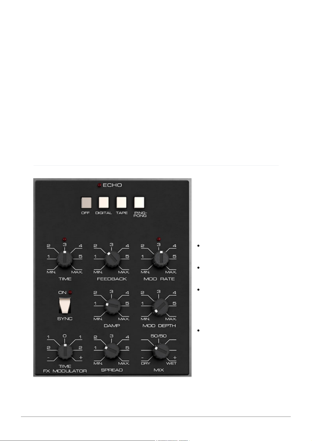
version, or to the current project tempo when the plug-in version is used in a
DAW. When engaged, the
Speed
knob snaps to note values ranging from
1/64th note triplet to 8 beats.
Depth- Sets effect depth, i.e. the amount of modulation.
FX Modulator- Sets the amount of sweep mod from the FX Modulator
section in the top left corner. To disable the Flange/Chorus's dedicated LFO,
set the
Depth
control to zero. This lets you use the FX Modulator only for
mod. Alternatively, the Flange/Chorus's internal mod can be combined with
the FX Modulator for unique modulation shapes (in this case, we recommend
enabling sync and experimenting with
Speed
subdivision settings for both).
Mix- Sets the ratio of clean to effected sound. Flanging and chorusing is
usually optimal at a 50/50 setting, but we've added the
Mix
control by
popular demand to allow more subtle (or warble-riffic) tones.
Echo
Atomika's Echo
includes digital, tape,
and ping-pong, plus
cool modulation
section.
Mode buttons-
Off- Disables Echo
effect.
Digital- A pristine
sounding digital delay.
Tape- Reproduces the
effect of a vintage
"space echo" tape
delay.
Ping Pong- Echoes
alternate between
audio channels.
Time- Sets delay time,
from 1 to 2000 ms. If
the
Sync
button is enabled, time settings snap to synchronized note values.
Cherry Audio Atomika Synthesizer User Guide - 27
Page 28

Feedback- Routes the output to the input for additional repeats. Be careful
at high settings as this can result in runaway feedback madness.
Mod Rate- Sets the rate of delay time modulation from 0.20 to 20 Hz.
Sync- The
Sync
switch locks the delay time to master tempo. When
engaged, the
Time
knob snaps to note values ranging from 1/64th note
triplet to 8 beats.
Sync
mode locks to the tempo in the top toolbar when
using the Atomika standalone version or the current project tempo when the
plug-in version is used in a DAW.
Damp- Attenuates high-frequencies as the knob amount is increased. Not
only does this create more natural sounding decays, it also reduces the
"stacking" effect that occurs with high feedback levels.
Mod Depth- Sets the depth of delay modulation. Lower settings give delays
a nice, subtle warble. Higher settings can result in the infamous Steve
Stevens "raygun" effect. (If I was that guy, I'd change my middle name to
Stefan, just to confuse people.)
Time FX Modulator- Sets the amount of sweep mod from the FX Modulator
section in the top left corner. To disable the Echo's mod LFO, make sure the
Mod Depth
control is set to zero. This lets you use the FX Modulator only for
mod. Or use both...
Spread- Alters the left and right channel delay times creating a stereoizing
effect. Greater amounts of spread increase the delay time differential and
thus the stereo separation.
Mix- Sets the ratio of clean to effected sound.
Reverb
Mode buttons-
Off- Disables Reverb effect.
Spring- Recreates mechanical spring-reverb effect often seen (and
kicked) in vintage guitar amps.
Plate- A medium-to-large studio plate-style algorithm.
Room- Recreates a vintage algorithmic-style medium room verb.
Hall- A large, hall-style reverb.
Galactic- Cherry Audio's exclusive, giant, spacey reverb.
Cherry Audio Atomika Synthesizer User Guide - 28
Page 29
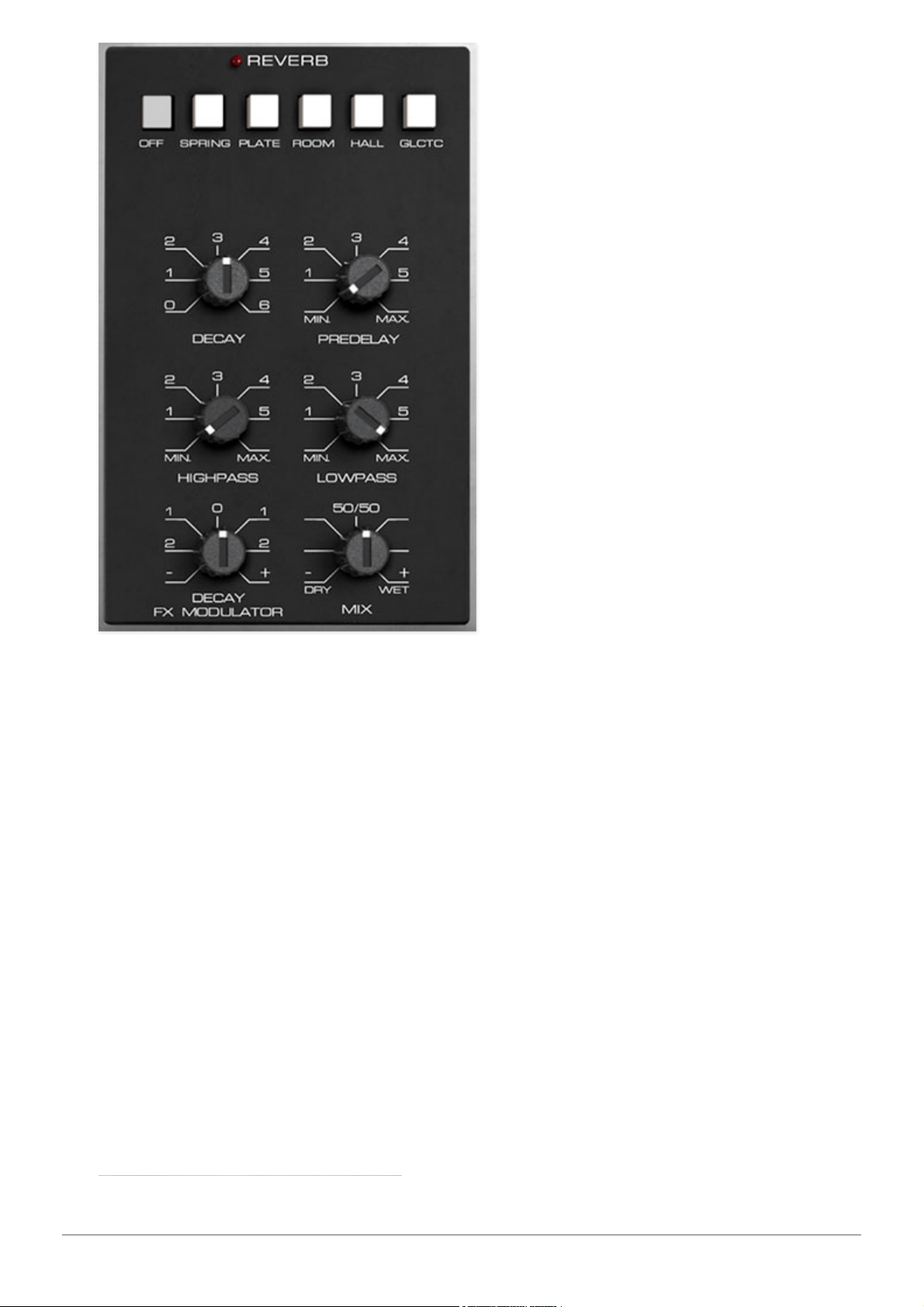
Decay- Sets the length of reverb
release time/size of room.
Predelay- Sets the length of
time until the onset of reverb
from 0 to 150 ms.
HP- A highpass filter affecting
wet reverb signal only. Low
frequencies are increasingly
attenuated as the knob setting is
increased.
LP- A lowpass filter affecting wet
reverb signal only High
frequencies are increasingly
attenuated as the knob setting is
decreased.
Decay FX Modulator- Sets the
amount of modulation of decay
time from the FX Modulator
section in the top left corner. To
disable the Flange/Chorus's
dedicated LFO, set the
Depth
control to zero. This lets you use the FX
Modulator only for mod.
Mix- Sets the ratio of clean to effected sound.
Cherry Audio Atomika Synthesizer User Guide - 29
Page 30
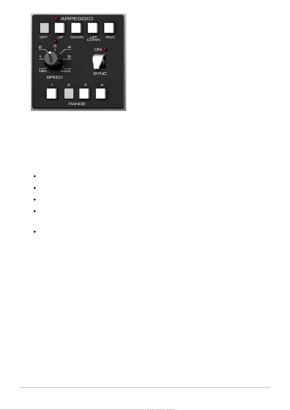
An arpeggiator is basically a step sequencer that plays each note of a chord
individually in an ascending or descending pattern across one or more
octaves.
Pattern buttons- These buttons enable the arpeggiator
and
select the
order in which the notes of chords are played.
Off- Arpeggio is disabled. You knew that.
Up- Notes play in order from lowest to highest.
Down- Notes play in order from highest to lower.
Up/Down
-Notes play from lowest to highest and back down from highest
to lowest.
Rnd (Random)- Notes are played in a random order.
Speed- Sets the playback speed of arpeggiator sequences, from 0.25 to 30
Hz (with
Sync
disabled).
Sync- Engaging the
Sync
button locks arpeggio timing to master tempo.
When engaged, the
Speed
knob snaps to note values ranging from 1/64th
note triplet to 8 beats.
Sync
mode locks to the tempo in the top toolbar when
using the Atomika standalone version or the current project tempo when the
plug-in version is used in a DAW.
Range buttons- Selects how many octaves the pattern will play before
repeating. Only one button can be pressed at any time.
Cherry Audio Atomika Synthesizer User Guide - 30
Page 31
Assigning internal and external hardware controls adds a whole new
dimension of control and musicality to patches, and it's really easy to do. The
MIDI Tab is where all controller assignments can be viewed and tweaked.
First we'll show how to assign an external hardware controller to an Atomika
control, then we'll go over all parameters in the MIDI Tab.
Basic External Hardware Control
Assignment
This is the quick, "I just want to assign a hardware control right now!,"
section. We recommend reading this whole section to best take advantage of
Atomika's nifty MIDI control assignments.
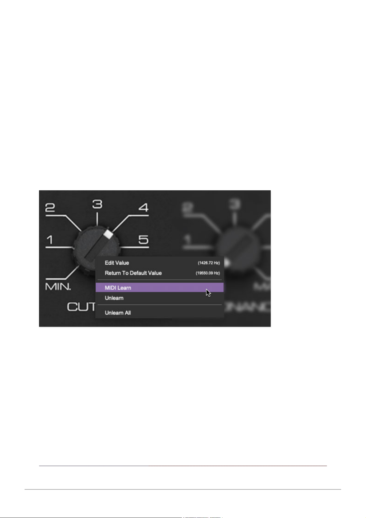
In this example, we’ll assign a hardware slider/knob control to the filter
Cutoff
knob.
Begin by right-clicking on the
Cutoff
knob in the Filter section and selecting
MIDI Learn.
A transparent purple overlay appears over the knob indicating
that it's in learn mode. Now move the desired hardware control device. The
purple overlay disappears and the hardware control will move the onscreen
knob. If you get cold feet (or accidentally put the wrong control into learn
mode), learn mode can be aborted by right-clicking and selecting
Stop
Learning
.
This is the basic procedure for assigning hardware controllers to almost any
Atomika control.
Cherry Audio Atomika Synthesizer User Guide - 31
Page 32
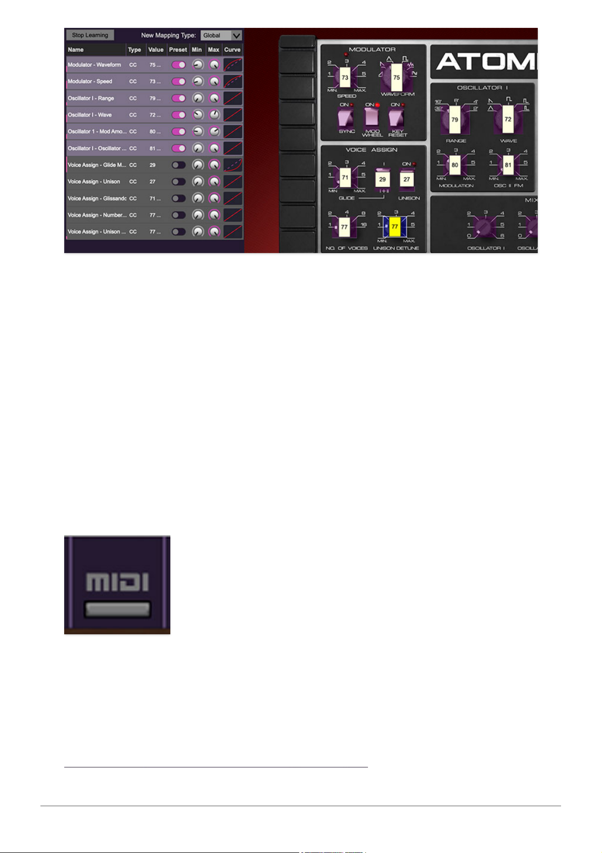
When in MIDI learn mode, any previously assigned controller numbers will
show in squares. These indicate the MIDI continuous controller number of the
assigned hardware control (these are also displayed in the
MIDI
library tab at
left).
Once a MIDI controller has been assigned, in addition to real-time control of
an Atomika parameter, you’ll also be able to record and play back controller
data from a DAW.
The MIDI Tab
This is command central for all MIDI controller assignments. Here you’ll be
able to see information about all currently assigned controllers and adjust
control ranges.
To view or hide the MIDI Tab, click the
MIDI
button in the purple top toolbar.
Cherry Audio Atomika Synthesizer User Guide - 32
Page 33
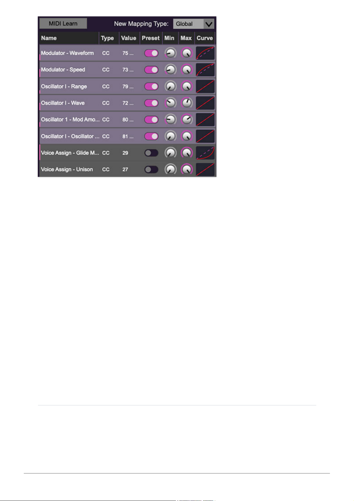
MIDI Learn button- This is almost exactly the same as enabling MIDI learn
mode by right-clicking a control. Click the
MIDI Learn
button to enter learn
mode (all controls turn purple). Unlike right-clicking on specific knobs, where
Atomika automatically exits controller assignment mode, clicking the
MIDI
Learn
knob "stays on" to enable assignment of multiple hardware controls.
This is handy for quickly assigning a bunch of sliders or the buttons of a gridstyle controller.
To assign multiple controls, click
MIDI Learn
, click an on-screen control, move
the desired hardware knob or slider, continue clicking and assigning onscreen controllers until all desired controls are assigned, then click
Stop
Learning
to exit learn mode.
Remember that a single hardware knob/slider/button isn't limited to
controlling just one parameter - a single hardware controller can
simultaneously operate as many controls as you'd like.
New Mapping Type- This popup menu selects whether newly assigned MIDI
mappings will be global (affects all sounds and doesn't change when
different presets are selected) or saved with individual presets.
MIDI Tab Columns
Name- Displays the name of the parameter being controlled.
Type- There are five possible types of controller automation in Atomika:
Cherry Audio Atomika Synthesizer User Guide - 33
Page 34

Note- Notes played on a MIDI keyboard controller, expressed as C-1 to G9
CC (MIDI Continuous Controller)- The standard 128 MIDI controller
numbers as defined in the MIDI spec. More specifically, these are the
controllers transmitted by hardware knob and slider controls. MIDI CC’s
can be used to control parameters in real-time or recorded and played
back within DAW software.
MMC (MIDI Machine Control)- The MIDI control protocol for tape
machine-style transport controls. Back in the dark ages, this was used to
control wonky old Tascam and Fostex reel-to-reel monsters, but it's useful
if your MIDI controller has tape-style transport control buttons.
Aftertouch- Besides sounding like a 1981 Melissa Manchester record,
some keyboard controllers transmit controller data when keys are pressed
and released as they're held down. The vast majority of keyboard
controllers with aftertouch transmit "mono" aftertouch only; in other
words, aftertouch data is the sum of all keys to one single data stream.
Key- This allows keys of the computer QWERTY keyboard to act as button
controls for Atomika's onscreen controls.
Value-Displays the specific automation controller. In the case of a
Note
this
would show a MIDI note number (C-1 to G9, for a MIDI CC, this would be the
MIDI CC controller number, etc. Clicking on the value opens a pop-up menu
where all values are displayed and can be selected.
Preset-This slider works in conjunction with the
New Mapping Type
menu. In
the left position (gray background), the MIDI mapping is global (affects all
sounds and doesn't change when different presets are selected), in the right
position (lavender background), the MIDI mapping is saved with, and only
affects the current sound preset.
The
Preset
switch is super nifty, because it means MIDI mappings
can easily be set to global or per-preset status at any time. (A lot of
folks asked us for this feature.)
Min- Sets a limit on the lowest value any automation control can set a
mapped controller to. This actually recalibrates the range of the automation
controller to the remaining parameter range.
Max- Sets a limit on the highest value any automation control can set a
mapped controller to. This actually recalibrates the range of the automation
controller to the remaining parameter range.
Cherry Audio Atomika Synthesizer User Guide - 34
Page 35
Super Tricky Min-Max Tricks
- Not only can parameter ranges be limited
via the the
Min
and
Max
knobs, mapped control destinations can be
completely inverted by setting the
Min
knob all the way up and the
Max
knob all the way down (or anywhere in between).
Limiting and inverting parameter ranges with the
Min/Max
controls is
particularly useful when multiplexing a single hardware control to operate
multiple parameters. Along with the
Curve
control, the customization
possibilities are super flexible.
Curve- These allow the customization of how incoming MIDI CC controls
affect the movement of Atomika's onscreen controls, ranging from
exponential to linear to logarithmic curves.
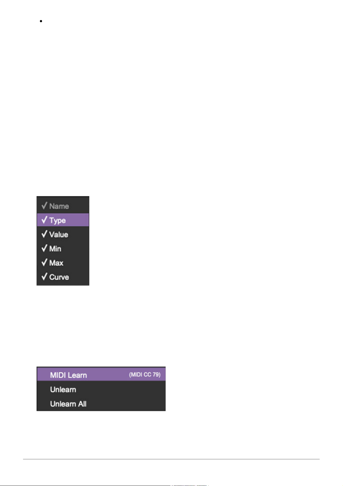
MIDI Tab Column Configuration
Right-Click Menus
Right-clicking anywhere in the top row (
Name, Type, Value
, etc.) displays the
column configuration menu. Checking/unchecking these allows hiding and
display of each column. This has no effect on assignments.
MIDI Tab Parameters Right-Click
Right-clicking on an assigned parameter opens the menu above.
Cherry Audio Atomika Synthesizer User Guide - 35
Page 36

MIDI Learn- This is used to change the controller assigned to a particular
parameter.
Unlearn- Deletes the selected automation parameter.
Unlearn All-Deletes all controller assignments for the patch. Atomika will
display a warning dialog prior to deletion in order to thwart potential unlearnrelated disasters.
Cherry Audio Atomika Synthesizer User Guide - 36
Page 37
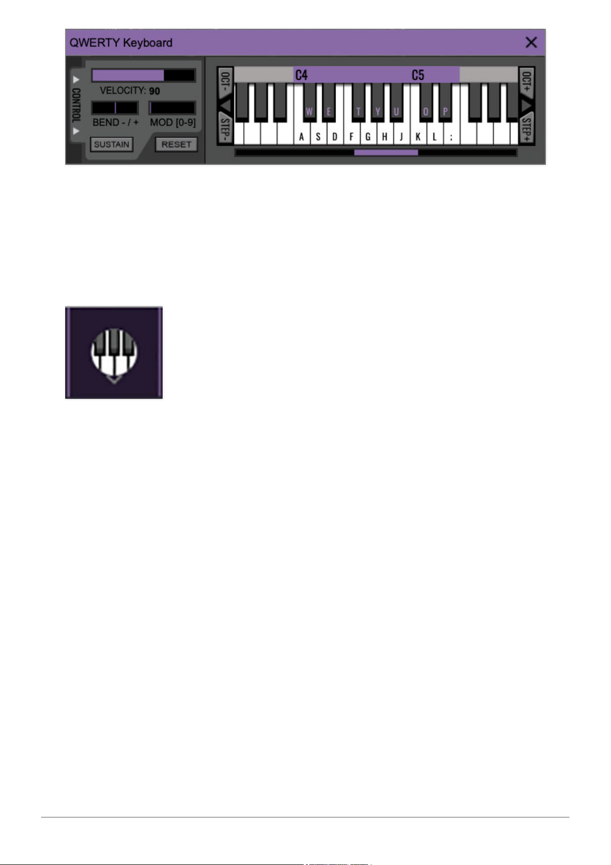
Atomika can be played by clicking its onscreen keyboard with a mouse or
trackpad, but if you don't have a MIDI keyboard attached to your computer,
there's a better way - your computer's QWERTY computer keyboard can be
used to play notes. We call this the "musical typing keyboard," or "MTK."
Following is a list of MTK keyboard modifiers and functions:
Opening and Closing the MTK- Click the the circular keyboard icon in the
top toolbar. To close the MTK, click the keyboard icon in the top toolbar, or
click the X in the top right corner.
Play Notes- To trigger notes, press the corresponding computer keyboard
key or mouse click the onscreen keys.
Adjust Currently Visible MTK Range- Slide the purple scroll bar
horizontally to adjust the currently visible keyboard range.
Adjust Overall Visible Keyboard Range- Clicking and dragging the right
edge of the MTL window allows the overall size of the window to be adjusted.
This lets you view more or less of the onscreen keyboard. Note that the MTK
window's borders cannot exceed the overall outside dimensions of the
Miniverse window.
Shift Range Up/Down Octave- Click the
OCT-
and
OCT+
buttons at the top
left and right of the onscreen MTK. The current range is displayed above the
keyboard.
Shift Range Up/Down Semitone- Click the
STEP-
and
STEP+
buttons at
the bottom left and right of the onscreen MTK. The current range is displayed
Cherry Audio Atomika Synthesizer User Guide - 37
Page 38

above the keyboard.
Hide/View Controllers- Clicking
CONTROL
at the far left hides and displays
velocity, bender, mod, and sustain control parameters. Hiding the control
view makes more space available for the keyboard.
Pitch Bend- To pitch a note or notes, press the + or - computer keyboard
keys while playing a note. Bend depth is fixed at a whole-step. Notes can
also be pitchbent by clicking the mouse in the
Bend
area.
Mod Wheel- To add mod wheel modulation, press the number keys from
0-9
(above the character keys) while playing a note. The modulation amount will
vary from none (0) to full modulation (9). Note that modulation will "stick" at
the selected number; to disable modulation, click the 0 key. Mod can also be
engaged by clicking the mouse in the mod bar area.
Sustain- The
Sustain
button mimics the functionality of a standard sustain
pedal. Click the [TAB] key to engage sustain, or [SHIFT]+[TAB] to lock it. The
Sustain
button can also be engaged by mouse clicking it.
Reset- Initializes all MTK parameters including keyboard range and control
parameters.
Cherry Audio Atomika Synthesizer User Guide - 38
Page 39
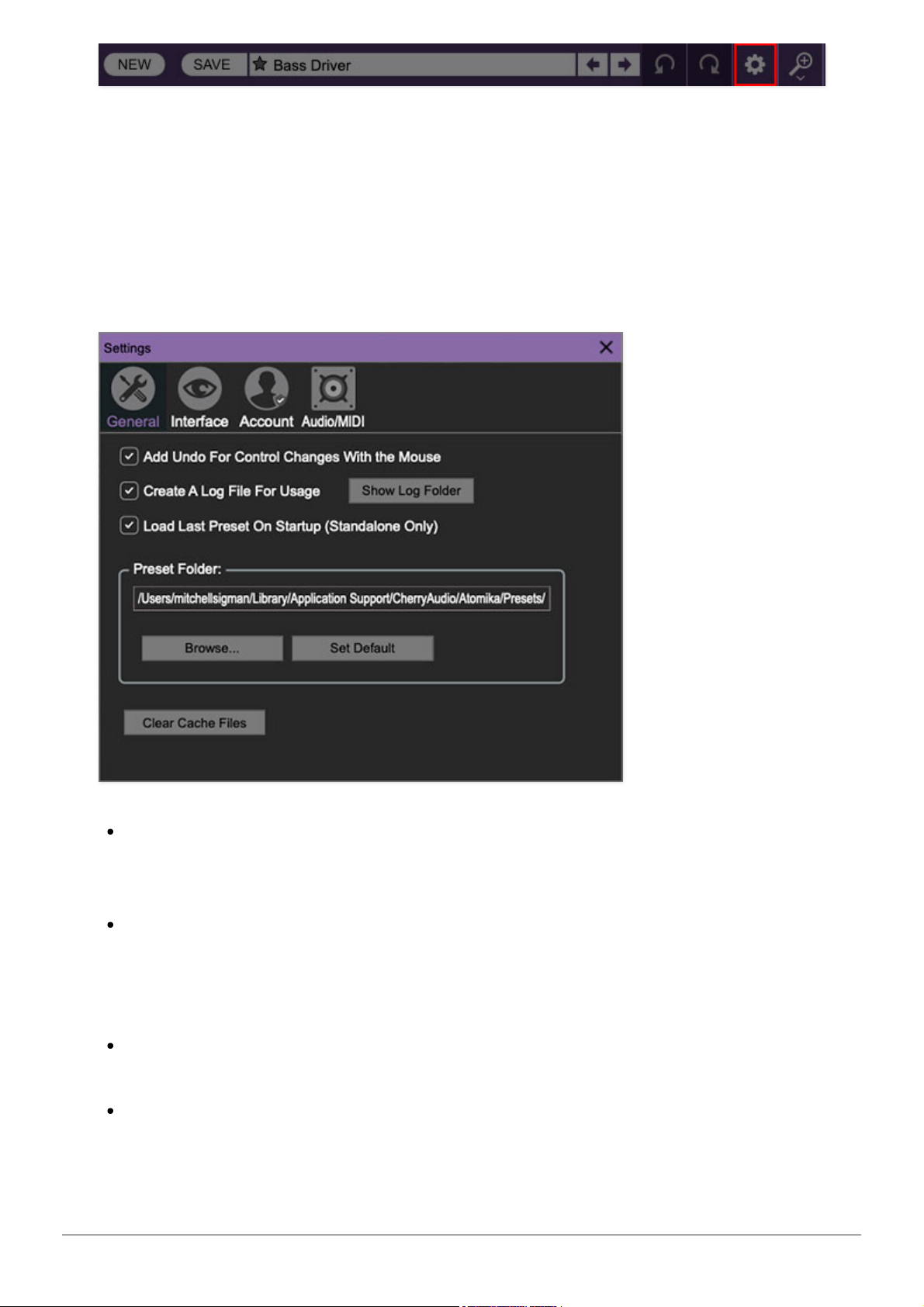
Clicking the settings gear icon opens a window with multiple tabs for
configuring various "under-the-hood" settings. These are mostly set-andforget kind of parameters - all the stuff you'll want to tweak is on the front
panel, as it should be!
General
Add Undo For Control Changes With the Mouse- Enabling this allows
undo of knob/slider/button adjustments. You’ll want this on if you want the
ability to undo all aspects of patch editing and programming.
Create A Log File For Usage- This creates a text doc of all of Atomika's
internal and routines during use. It is mainly intended for our tech staff
should you experience any issues. Clicking
Show Log Folder
opens the
folder containing Atomika log file docs.
Load Last Preset On Startup (Standalone Only)- Automatically loads
the last preset used when Atomika standalone version is started.
Preset Folder- Displays the current location of Atomika's sound presets.
This can be changed by clicking and typing in the field.
Cherry Audio Atomika Synthesizer User Guide - 39
Page 40
Browse... - Displays the current location of preset folder in the file
manager.
Set Default- Sets the current displayed
Preset Folder
path as the
default location
Clear Cache Files- Deletes all log files, temporary sounds, and the
image cache.
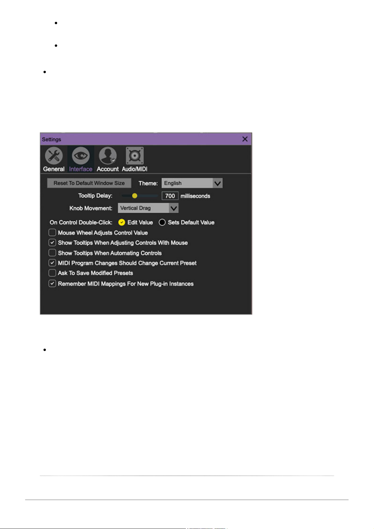
Interface
Allows customization of Atomika’s user interface settings.
Reset To Default Window Size- Resets the Atomika workspace to
default size. Use this to reset the window size if the window somehow
becomes too large for your display and can't be resized (pretty sure we
fixed that bug a while back though!).
Cherry Audio Atomika Synthesizer User Guide - 40
Page 41
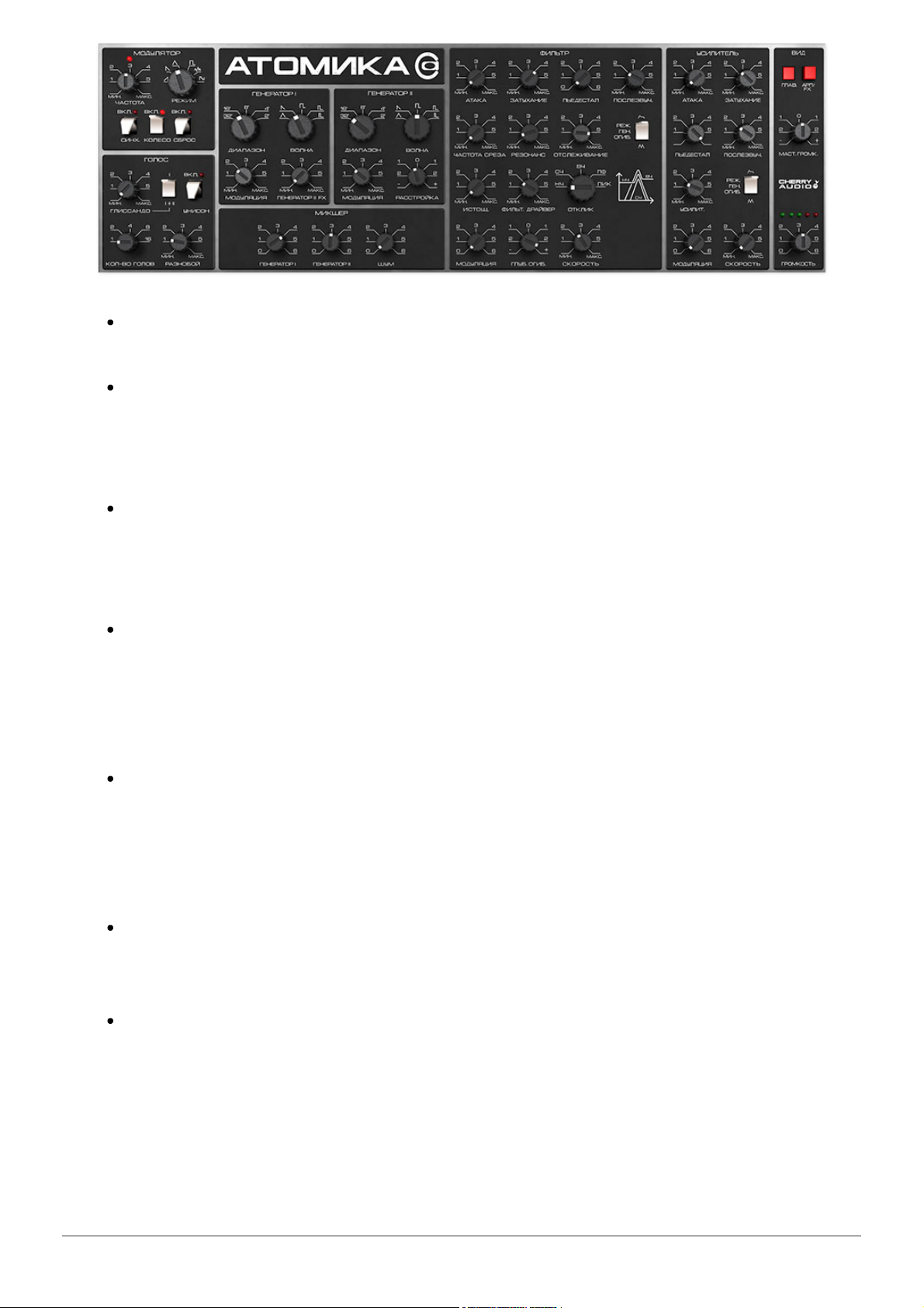
Theme- This popup menu lets you choose between panel labeling in
English, or Cyrillic Russian, like the original instrument. Pretty cool, huh?
Tooltip Delay- Tooltips are those informative bits of text that pop up
when hovering over a control (go ahead and try it, we’ll wait…). The
Tooltip Delay
setting defines how long you must hover before the tooltip
pops up.
Knob Movement- Defines how mouse movements relate to turning
onscreen knobs. It defaults to
Vertical Drag
, but can be changed to
Horizontal Drag
, or
Rotary Drag
if you're one those folks that cut their
teeth on the
Steinberg Model E
VST back in 2000.
On Control Double-Click- Defines what happens when the mouse is
double-clicked on a control. If
Edit Value
is selected, an exact number can
be entered by typing the number and hitting [ENTER] or [RETURN]. If
Sets
Default Value
is selected, double-clicking a control resets it to its default
value.
Mouse Wheel Adjusts Control Value- Enabling this lets you adjust
knob, slider, and switch values by moving the mouse wheel. This works
great with a standard mouse wheel, but you'll want to disable it if you're
using an Apple Magic Mouse (which will move the control AND scroll the
window).
Show Control Tooltips When Adjusting Controls With Mouse-
Displays parameter tooltips/values when the mouse is hovered over a
control or as a control is moved with mouse clicked.
Show Tooltips When Automating Controls- Displays parameter
tooltips/values next to controls any time a control is changed, i.e. if a
control is moved via an assigned MIDI controller or a
Perform
panel knob,
etc.
Cherry Audio Atomika Synthesizer User Guide - 41
Page 42
MIDI Program Changes Should Change Current Preset- Allows MIDI
program change messages to change Atomika patches.
Ask To Save Modified Presets- This opens a dialog window asking if
you'd like to save changes if a patch has been edited and a new patch is
selected. If you're the type that likes to click through presets and tweak a
control here and there, it can be annoying to have a window pop-up
asking if you'd like to save every time you switch presets - if you're that
person, keep this off.
Remember MIDI Mappings For New Plug-in Instances- When
enabled, Atomika remembers all global MIDI Tab controller settings.
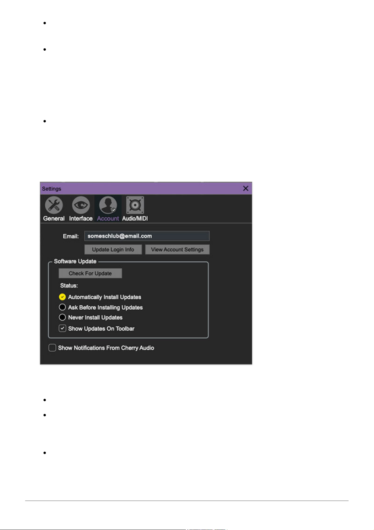
Account
Settings for your personal login information and account.
Email- Displays the email address of the current login.
Update Login Info- No, this isn’t a place for news and tour dates for
yacht rock superstar, Kenny Loggins. Clicking this opens the same email
and password login screen you’ll see when initially launching Atomika.
View Account Settings- This opens your personal account page on the
Cherry Audio Store website containing information about modules
Cherry Audio Atomika Synthesizer User Guide - 42
Page 43

purchased and more.
Software Update
We often fix bugs and make improvements; below are options defining
how Atomika handles updates.
Check For Update- Click this to see if an updated version of Atomika
available.
Status-
Automatically Install Updates- Updates are automatically downloaded
and installed.
Ask Before Installing Updates- By default, Atomika automatically
downloads new versions of modules when available. Checking this box
defeats automatic updates and will ask if you’d like to install updates
when they become available.
We’ll never make changes that can potentially “break” existing patches
but we recommend enabling
Ask Before Installing Updates
if you’re using
Atomika for live performances or other “mission critical” situations.
Never Install Updates- Atomika never automatically installs updates.
Show Updates On Toolbar- Checking this will display an icon in the
toolbar next to the logo letting you know there's an update available.
Show Notifications From Cherry Audio- We occasionally will fire off inapp advertisements; disabling this checkbox will hide them. We hate
repetitive, annoying ads as much as you, so we won't use this feature too
often. When we do, it'll be for something super cool (like a killer sale), so we
recommend leaving it on.
Audio/MIDI
Cherry Audio Atomika Synthesizer User Guide - 43
Page 44
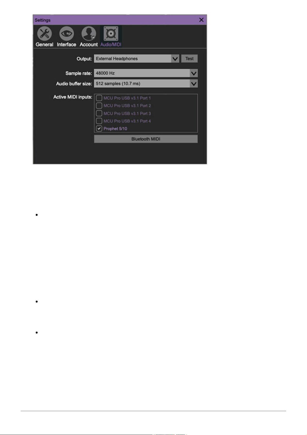
Not to be confused with audiomidi.com, where I used to work, these are
settings for audio and MIDI hardware input and output.
This tab is only visible in the standalone version of Atomika.
Output- Use this drop-down menu to choose a physical audio output
source. This defaults to
Built-In Line Output
, i.e. your computer’s onboard
system audio, but you’ll get better fidelity with an external professional
audio interface. The biggest audible difference is usually reduced
background noise or hum, but external audio hardware also offers greater
flexibility in terms of number of inputs and outputs and built-in mic or lowlevel instruments pres (i.e. electric guitars). The
Test
button will produce a
sine wave when clicked; this will help with troubleshooting, aka, “WHY
THE HECK ISN’T THIS MAKING ANY NOISE?!?”
Sample Rate- This sets Atomika's global sample rate. Lower sample
rates offer better performance, but if you have a fast computer, high
sample rates may offer slightly improved fidelity.
Audio Buffer Size- As with any digital audio app, this defines
performance vs. note latency, and will largely depend upon computer CPU
speed. A professional external audio interface will almost always exhibit
better performance than “built-in” system audio. Lower settings will result
in less latency (in the form of faster response to notes played), but will
increase the chances of audio gapping or crackling noise.
Cherry Audio Atomika Synthesizer User Guide - 44
Page 45

Active MIDI Inputs- Enable MIDI input sources, i.e. MIDI/USB keyboards,
pad controls, MIDI knob/fader control surfaces, etc. Check boxes to enable
one or more devices. If a MIDI/USB controller isn't working in
standalone mode, make sure the appropriate box is checked here.
(We put this this piece of info
way
in the back of the manual, to make it
extra challenging to figure out why things aren't working.)
Cherry Audio Atomika Synthesizer User Guide - 45
 Loading...