

Obey™ 10
Snapshot
DMX Controller
USER MANUAL
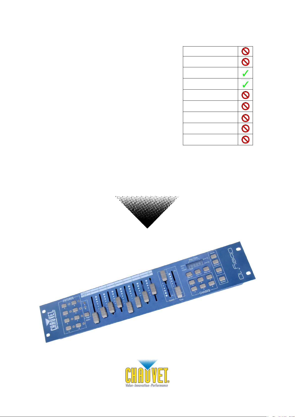
Ok on Dimmer
Outdoor OK
Sound Activated
DMX512
Master/Slave
115V/230V Switch
Replaceable Fuse
User Serviceable
Duty Cycle
Chauvet, 5200 NW 108th Avenue, Sunrise, FL 33351 U.S.A.
(800) 762 -1084 – (954) 929-1115
FAX (9 54) 92 9-5560
www.ch auvetlighting.c om

TABLE OF CONTENTS
1. Before You Begin ..........................................................................................................................3
WHAT IS INCLUDED .............................................................................................................................................................. 3
UNPACKING INSTRUCTIONS ................................................................................................................................................... 3
SAFETY INSTRUCTIONS......................................................................................................................................................... 3
2. Introduction ...................................................................................................................................4
FEATURES.......................................................................................................................................................................... 4
PRODUCT OVERVIEW (FRONT) ............................................................................................................................................... 4
PRODUCT OVERVIEW (REAR PANEL) ....................................................................................................................................... 5
COMMON TERMS ................................................................................................................................................................. 5
3. Operating Instructions ..................................................................................................................6
SETUP ............................................................................................................................................................................... 6
Setting up the System .................................................................................................................................................. 6
Fixture Addressing ....................................................................................................................................................... 6
Physical Fader Assignment (OPTIONAL SETUP) ......................................................................................................... 6
Reverse Channel Output (OPTIONAL SETUP) ............................................................................................................. 7
Reset to Factory Default ............................................................................................................................................... 7
Blackout....................................................................................................................................................................... 8
Fade Assignment (OPTIONAL SETUP) ........................................................................................................................ 8
PROGRAMMING ................................................................................................................................................................... 8
Entering Program Mode ............................................................................................................................................... 8
Delete a Step ............................................................................................................................................................... 9
Delete Chase ............................................................................................................................................................... 9
ADDING A STEP TO A CHASE ................................................................................................................................................. 9
Delete a Chase ............................................................................................................................................................ 9
PLAYBACK .........................................................................................................................................................................10
Manual Run Chase .....................................................................................................................................................10
Running in Sound-Mode ..............................................................................................................................................10
Running in Auto-Mode .................................................................................................................................................10
UNNING SEQUENTIAL CHASES.............................................................................................................................................10
R
4. Appendix ..................................................................................................................................... 11
RETURNS ..........................................................................................................................................................................11
CLAIMS .............................................................................................................................................................................11
TECHNICAL SPECIFICATIONS ................................................................................................................................................11
Obey™ 10 User Manual 2 Rev.3

Please read these instructions carefully, which includes important information
about the installation, usage and maintenance of this product.
1. BEFORE YOU BEGIN
What is Included
1 x Obey™ 10 contr oller
1 x DC 12V 500mA, 110V Power Adapter or 230V Power Adapter
1 x Manual with warranty card
Unpacking Instructions
Immediately upon receiving a fixture, carefully unpack the c arton, check the c ontents to ensur e
that all parts are present, and have been received in good condition. Notif y the shipper
immediat ely and retain packing material for inspection if any parts appear damaged from
shipping or the carton itself shows signs of mishandling. Save the carton and all packing
materials. In the event that a fixture must be returned t o the factory, it is important that the fixture
be returned in the original factory box and packing.
Safety Instructions
• Please keep this User Guide for futur e consultation. If you s ell the unit to another user, be sure
that they also receive this instr uction booklet.
• Always make sure that you are connecting to the pr oper voltage and that the line voltage you are
connecting to is not higher than that stated on decal or rear panel of the fixture.
• This product is intended f or indoor us e only!
• To prevent risk of fire or shock, do not expos e fixture to rain or moistur e. Make sure there are no
flammable materials close to the unit while operating.
• The unit must be installed in a location with adequate ventilation, at least 50cm from adjacent
surfaces. Be sure that no ventilation slots ar e blocked.
• Always disconnect from power source before servicing or replacing lamp or fus e and be sur e to
rep lace with s ame lamp source.
• In the event of serious operating problem, stop using the unit immediately. Never try to repair the
unit by yourself. Repairs carried out by unskilled people can lead to damage or malfunction.
Please c ontact the nearest authorized technical assistance center. Always us e the s ame type
spare parts.
• Do n ot connect the device to a dimmer pack.
• Make sur e power cord is never crimped or damaged.
• Never disconnect power c ord by pulling or tugging on the cord.
• Do not operate this devic e in more than 113° F ambient temperature conditions.
Caution! There are no user-serviceable parts inside the unit. Do not open the housing or
attempt any repairs yourself. In the unlikely event your unit may require service,
please contact CHAUVET at: 954-929-1115.
Obey™ 10 User Manual 3 Rev. 3
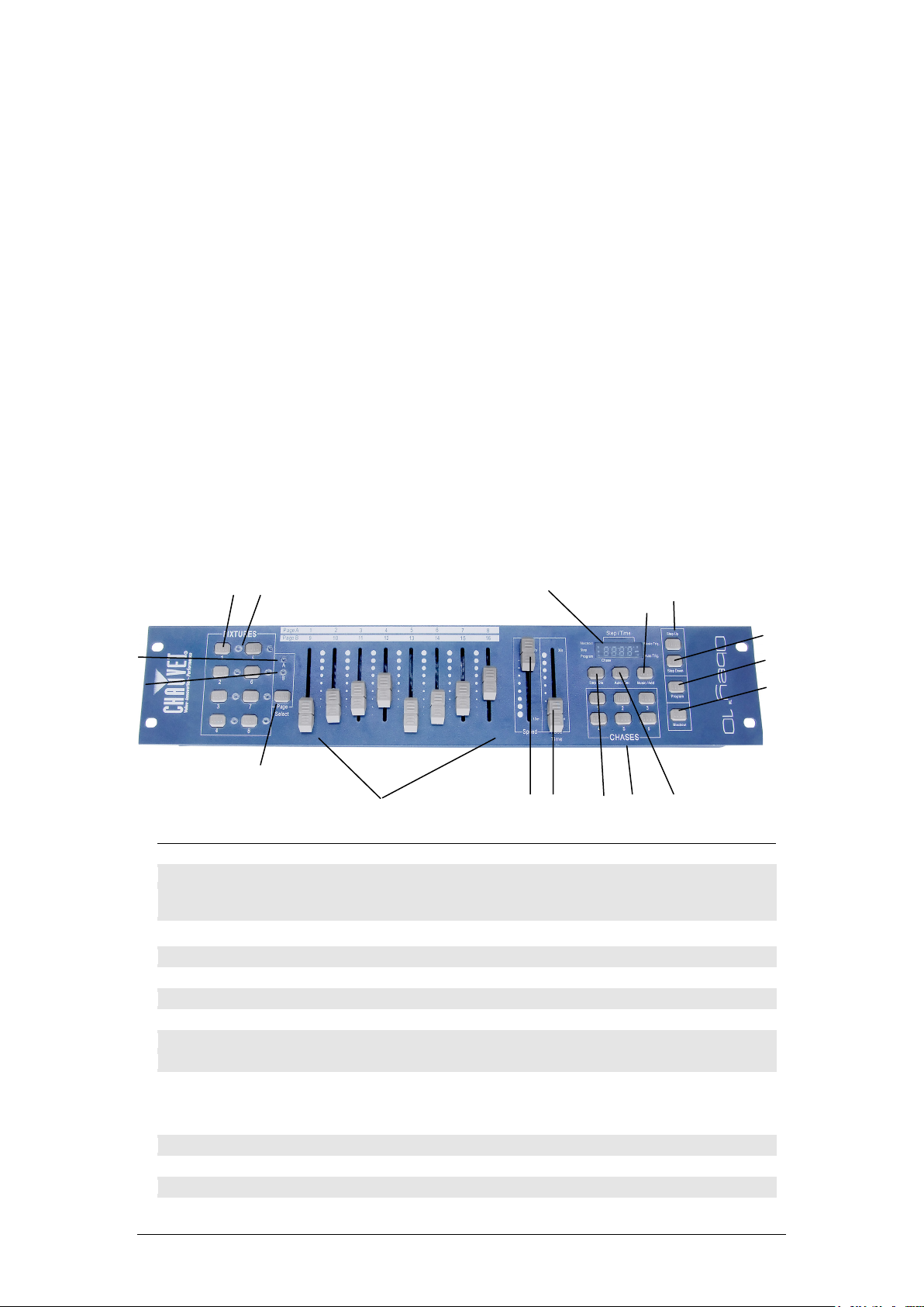
Item
Button or Fader
Function
1
Fixture select buttons
Fixture selection
2
Fixture indicator LED's
Indicates the fixtures currently selected
3
Channel faders
For adjusting DMX values, Ch 1~8 can be adjusted immediately after pressing the
respective scanner select button, Ch 9~16 after pressing the Page select button
4
Page A Indicator LED
Represents Ch 1~8 range selected
5
Page B Indicator LED
Represents Ch 9~16 range selected
6
Page select button
Press to toggle between pages of control.
7
Program button
Used to enter programming mode
8
Music/Add Copy button
Used to activate Music mode and as the confirm command during programming
9
LED display window
Status window displays pertinent operational data
10
Step Up button
Function button to scroll through steps in a scene during programming and playback
11
Step Down button
Function button to scroll through steps in a scene during programming and playback
12
Blackout button
Reduces all DMX values to zero.
13
Auto/Del button
Used to activate Auto mode and as the delete function key during programming
14
Chase buttons
Chase memory 1 ~ 6
15
Speed fader
This will adjust the hold time of a scene or a step within a chase
16
Fade Time fader
Also considered a cross-fade, sets the interval time between two scenes in a chase
17
Step/Dis button
This is used to change steps and modify the display from 0-255 or 0-100%
1
2
4
7
9
8
12
10
11
6
3
15
16
13
14 5 17
2. INTRODUCTION
The Obey™ 10 is a univers al intelligent lighting controller. It allows the control of 8 fixtur es
composed of 16 channels each and up to 6 pr ogrammable chases. Si x c hase banks can contain
up to 999 steps. Programs can be triggered by music, automatic ally or manually. Channel
assignments can be reprogrammed for ease of contr olling diff erent f ixtures. On the surface you
will find various programming tools such as 8 universal channel sliders, quick access scanner
buttons, and an LED display indicator for easier navigation of c ontrols and menu functions.
Features
• Universal DMX-512 controller
• Controls up to 8 int elligent lights of up to 16 channels each
• 128 DMX channels of control
• 6 sets of chas es containing 999 scenes each
• Reversible sliders
• Re-assignable channels
• Sequential linking of chases
• Grab any fixture on the fly
• Beat activation and auto run
• DMX polarity s elector
• 2-space (2U) rack mount
Product Overview (front)
Obey™ 10 User Manual 4 Rev. 3

20
Item
Button or Fader
Function
18
Power On/Off switch
Used to turn the power on/Off while it is plugged into the power adapter
19
DMX polarity switch
May be used to change signal polarity
20
DMX output connector
DMX control signal
21
DC Input jack
Main power feed
21
18
19
Product Overview (rear panel)
Common Terms
The following are common terms used in intelligent light
programming.
Blackout is a state where all lighting fixtures’ light output are set to 0 or off, usually on a
temporary basis.
DMX-512 is an industry standard digital communication protocol us ed in entertainment lighting
equipment. For more information read Sections “DMX Primer” and “D MX Control Mode” in the
Appendix.
Fixture refers to your lighting instrument or other device such as a fogger or dimmer which you
can control.
Programs are a bunch of scenes stacked one after another. It can be programmed as either a
single scene or multiple scenes in sequence.
Scenes are static lighting states.
Sliders are als o known as f aders.
Chases can also be called progr ams. A chase consists of a bunch of scenes stacked one after
another.
Scanner refers to a lighting instrument with a pan and tilt mirror; however DMX controllers can
use this term to control any DMX-512 compatible device as a generic fixture.
MIDI is a standard for representing musical information in a digital format. A MIDI input would
provide external triggering of sc enes using midi device such as a midi keyboard.
Standalone refers to a fixtur e’s ability to function independently of an external controller and
usually in sync to music, due to a built in microphone.
Fade slider is us ed to adjust t he time between scenes within a chase.
Speed slider affects the amount of time a scene will hold its state. It is also considered a wait
time.
Shutter is a mechanical device in the lighting fixture that allows you to block the lights path. It is
often us ed to lessen the intensity of the light out put and to strobe.
Patching refers to the process of assigning faders to a DMX channel within a fixture.
Playbacks can be either scenes or chases that are dir ectly called to execution by the user. A
playback can also be considered program memory that c an be recalled during a show
Obey™ 10 User Manual 5 Rev. 3

F
SCANNER #
D
DMX S
ADDRESS
B
SWITCH TO THE “ON POSITION”
1 1 1
2
17
1,5
3
33
1,6 4 49
1,5,6 5 65
1,7 6 81
1,5,7
7
97
1,6,7
8
113
1,5,6,7
Action
Example: Copying Scanner 1 into
Notes
3. OPERATING INSTRUCTIONS
Setup
Setting up the System
1) Place the Obey™ 10 on a level surf ace.
Note! The Obey™ 10 can also be rack mounted, occupy ing two rack spaces (2U).
2) Plug the AC to DC power supply into the system back panel and into the mains outlet.
3) Plug in your DMX c able(s) to your intelligent lighting as described in the respective fixture’s
manual. For a quick overview of DMX see the “DMX Primer” section.
4) Reset the system using the instructions on page 9.
Fixture Addressing
The Obey™ 10 is programmed to c ontrol 16 channels of DMX per fixture. Therefor e, the fixtures
you wish to control with the corresponding “FIXTURE” buttons on the unit must be spaced 16
channels apart (check the respective fixture’s manual for how to enter the inf ormation into the
fixture).
Note: failure to use these DMX assignments may cause a lack of control of the fixtures.
IXTURE OR
EFAULT
TARTING
Physical Fader Assignment (OPTIONAL SETUP)
Use this feature to combine or unify fixture control attributes f or different fixtures. For example; if
you were controlling 4 moving mirrors and 4 moving yokes, the color, gobo and dimmer channels
may not line up ideally on the physical f aders. Use this function to re-assign the dimmer, color
and gobo channels to faders 1, 2 and 3. From now on you will be able to control t he s ame
attributes on all fixtures using the same fader location.
1) Press and hold PROGRAM & STEP/DIS
buttons together (1) time to access the
channel assignment mode.
2) Press a FIXT URE button that represents
the fixtur e whose faders you would like to
re-assign.
3) Move the SPEED fader until you arrive at
controller channel (number).
4) Move the FADE TIME fader t o s elec t the
DMX channel that you wish to move to.
5) Press the MUSIC/ADD button to confirm
setting. All FIXTURES LED indicators will
flash to confir m successful copy.
6) Repeat steps 3 ~ 5 as oft en as necess ar y.
If you wish to copy a scanner’s physic al
assignments to another scanner, continue by
following steps 7-13. If you do not wish to do
this, press and hold PROGRAM & TAPSYNC
buttons (2) times to exit mode.
INARY DIPSWITCH SETTINGS
All physical faders can be re-assigned to output
on a different DMX channel. Faders are given a
channel number and are labeled on the surface of
the controller as such.
Obey™ 10 User Manual 6 Rev. 3

Scanner 2
Action
Copying Scanner 1 into
Notes
Action
Notes
7) Press and hold FIXTURE button # 1.
8) While holding button # 1 press FIXTURE
button # 2.
9) While holding FIXTURE buttons # 1 and #
2, press and hold MUSIC/ADD button.
10) Release SCANNER button # 1 first before
releasing SCANNER button # 2.
11) Release MUSIC/ADD button.
12) All FIXTURES LED indicators will flash to
confirm successful copy.
13) Press and hold PROGRAM & STEP/DIS
buttons (2) tim es to exit mode.
Reverse Channel Output (OPTIONAL SETUP)
1) Press and hold PROGRAM & STEP/DIS
buttons together (2) times to access the
channel assignment mode then press the
FIXTURE button.
2) Selec t FIXTURE.
3) Move the SPEED fader until you arrive at
the controller channel you wish to alter.
4) Move the FADE TIME fader all the way up
until N changes to Y.
If you wish to copy a scanner’s r evers e channel
assignments to another scanner, continue by
following steps 5-11. If you do not wish to do
this, press and hold PROGRAM & TAPSYNC
buttons (1) times to exit mode.
Example:
Scanner 2
5) Press and hold FIXTURE button # 1.
6) While holding button # 1 press FIXTURE
button # 2.
7) While holding FIXTURE buttons # 1 and #
2, press and hold MUSIC/ADD button.
8) Release FIXTURE button # 1 first before
releasing FIXTURE button # 2.
9) Release MUSIC/ADD button.
10) All FIXTURES LED indicators will flash to
confirm successful copy.
11) Press and hold PROGRAM & STEP/DIS
buttons (1) times to exit mode.
You can permanently reverse the output of any
given channel on the controller.
Reset to Factory Default
1) Press the STEP UP and AUTO/DEL
buttons simultaneously.
2) All LEDs will flash, indic ating a successful
reset of the controller.
This will erase all saved Chases!
This will work in any mode: Program or
Playback.
Obey™ 10 User Manual 7 Rev.3

Action
Notes
Action
Notes
hold the parameters changed for that fixture in the
Blackout
The Blackout button brings all lighting output to 0 or off (also called the home position of the
unit).
Fade Assignment (OPTIONAL SETUP)
Use this feature to turn the fade slider on or off for a c ertain channel. This is most useful when
you want the fade time to affect the pan/tilt of a fixture for smoother movements, but do not wish
to use this function on things such as shutter or color or gobo, as these should switch very fast
most tim es.
Programming
Entering program mode
3) Press and hold BLACK OUT & STEP/DIS
buttons together (2) times to acc ess the
channel assignment mode. then press the
FIXTURE button.
4) Selec t FIXTURE.
5) Move the SPEED fader until you arrive at
the controller channel you wish to alter.
6) Move the FADE TIME fader all the way up
until N changes to Y.
7) Press the MUSIC/ADD button.
8) Release MUSIC/ADD button.
9) All FIXTURES LED indicators will flash to
confirm successful setting.
10) Press and hold BLACKOUT & STEP/DIS
buttons (1) times to exit mode.
A program (bank) is a sequence of different scenes (or steps) that will be called up on e af t er
another. In the Obey™ 10, 6 programs can be created with up to 999 steps each.
Press the PROGRAM button f or 3 s econds until an LED dot next to the label PROGRAM blinks.
This indicates that the us er is in programming mode.
1) Press and hold the PROGRAM button f or
3 seconds.
2) Selec t a FIXTURE to program.
3) Select a Chase to store the program t o
(1~6).
4) Compose a look by moving the FADERS.
(Changes in fixture attribute such as colors
and gobos.) Press PAGE SELECT to
access Channels 9~16 on the faders.
5) To program another FIXTURE press the
FIXTURE button you have just f inished
programming then s elect another
FIXTURE button to program.
6) Repeat steps 2 ~ 4 until you have your
look.
7) Tap M USIC/ADD button to store.
8) All FIXTURES LEDs will flash, indicating a
successful save of the step to the memor y.
9) The display will automatic ally go on to the
next step. Us e the St ep Up and Step
Down butt ons to navigate through the
existing steps in the Ch as e.
10) Repeat steps 2 ~ 8 to record more scenes.
( Read Important notes on the right ->)
11) To exit program mode, hold the
PROGRAM button f or 3 s econds. The
controller will default to a BLACKOUT
when exiting the programmer.
This will permanently turn on/off the fade time for
a channel, until the user turns it back on/off.
Deselect Blackout if LED is lit.
A FIXTURE button represents one lighting
fixture.
You can access channels 9~16 by pressing the
Page Select button. This is necessary for fixtures
that use more than 8 channels of control. When
switching pages it will be necessary to move
previously moved faders up then down to activate.
Pressing the same FIXTURE button again will
program scene.
There are 999 scenes available for every chase.
Obey™ 10 User Manual 8 Rev.3

Action
Notes
Action
Notes
Action
Notes
Action
Notes
Delete a Step
12) Press the PROGRAM button f or 3
seconds.
13) Press the Chase butt on (1~6) for th e
corresponding chase you wish to edit.
14) Locate the step in the program by using
the Step Up and Step Down buttons.
15) Press the Auto/Del button to delete the
current step.
16) All FIXTURES LEDs will flash, indicating a
successful delete of the step from the
memory
17) When you have finished deleting the
steps, press & hold the Program button for
3 seconds to exit the Program mode.
Delete Chase
1) Press the PROGRAM button for 3
seconds.
2) Press and hold the AUT O/DEL button
while pressing the Chase you want to
delete.
3) All LED’s will flash, indicating that the
Chase was successfully erased.
Adding a Step to a Chase
Deselect Blackout if LED is lit.
The currently selected scene will be outputted to
the light fixtures connected to the DMX output.
! This will erase all Steps in the Chase!!!
Delete a Chase
1) Press and hold the PROGRAM button f or
3 seconds to enter programming mode.
2) Press the desired CHASE (1~6) button.
3) Use the Step Up/Step Down buttons to
scroll through the chase and arrive at the
step number for which you would like to
add a step to.
4) Selec t a FIXT URE butt on.
5) Adjust the Faders to the desired look on
stage.
6) Press Music/Add button and one step
number will be added after the previously
displayed step number. All FIXTURES
LED indicators will flash to confirm
successful copy.
7) Repeat steps 3~6 until all scenes have
been added to the chase.
8) Press and hold the PROGRAM button f or
3 seconds to exit programming mode.
1) Press and hold the PROGRAM button f or
3 seconds to enter programming mode.
2) Press the CHASE button (1~6) to be
deleted.
3) Press and hold the AUTO/DE L button and
the respective CHASE button then release
to delete the chase. All LED’s will blink 3
times. All FIXTURES LED indicators will
flash to confir m successful copy.
The step will be added after the scene displayed
on the digital readout.
Steps will remain programmed on the controller.
Only the chase is affected.
Obey™ 10 User Manual 9 Rev.3

Action
Notes
Action
Notes
Action
Notes
Action
Notes
Playback
Manual Run Chase
When power is first turned ON, the controller will be in manual sc ene mode.
1) Make sure neither M USIC TRIGGER nor
AUTO TRIGGER LED's on the LED
display are on.
2) Select the program CHASE button that
stores the scene you want to run manually
by using the STEP UP/DOWN.
Running in Sound-Mode
1) Press the MUSIC/ ADD button until the
MUSIC TRIGGER LED turns on.
2) Selec t th e CHASE you wish to operate.
3) Press the MUSIC/ BANK-COPY to exit.
Running in Auto-Mode
1) Press and hold the AUT O/ DEL button until
the AUTO TRIGGER LED turns on.
2) Selec t th e CHASE you wish to operate.
3) You can set the time between steps by
moving the SPEED fader and the f ad e
time of the step by moving the FADE
TIM E fad er.
4) You can change Banks while in operation
by using the STEP UP/DOWN buttons.
If you are in programming mode you can also
press and hold the PROGRAM button until the
Program LED goes off.
In the Sound mode, programs will be triggered by
the sound using its built-in microphone. All scenes
in a Bank will chase.
In the Auto mode, programs will be triggered by
controllers fade and speed time as set on the
faders. All scenes in a Bank will chase.
CAUTION! The fade setting should never be
slower than the speed setting or the scene will
never complete execution.
Running Sequential chases
1) Press either AUTO /DEL or MUSIC/ADD
buttons to select the trigger mode.
2) Press the CHASE button for each chase
you wish to playback.
3) Adjust the Chase speed by changing the
SPEED fader.
Chases must already be programmed.
The chases will run in the order they are pressed
Obey™ 10 User Manual 10 Rev.3

4. APPENDIX
Returns
Returned merchandise must be sent prepaid and in the original packing; call tags will not be
issued. Package must be clearly labeled with a Return Authorization Number (R MA #). Products
returned without an RMA # will be refus ed. Call CHAUVET® and request an RMA # prior to
shipping the fixtur e. Be prepared to provide the model number, serial number and a brief
description of the c ause for the return. Be sure to properly pack fixture, any shipping damage
resulting from inadequat e packaging is the customer’s responsibility. CHAUVET® reserves the
right to use its own discretion to repair or replace product(s). FedEx packing or double-boxing
are recommended.
Note: If you are given an RMA #, please include the following information on a piece of
paper inside the box:
1) Your name
2) Your address
3) Your phone number
4) A brief description of the symptoms
Claims
Damage incurred in shipping is the responsibility of the shipper; therefore the damage must be
reported to the carrier upon receipt of merchandise. It is the cust omer's responsibility to notify
and submit claims with the shipper in the event that a fixture is damaged due to shipping. Any
other claim for items such as missing component/part, damage not related to shipping, and
concealed damage, must be made within seven (7) days of receiving merchandise.
Technical Specifications
WEIG HT & DIMENSI ONS
Length .............................................................................................................................................................. 19 in (482 mm)
Width ................................................................................................................................................................. 3.5 in (89 mm)
Height ................................................................................................................................................................ 3.5 in (89 mm)
Weight ............................................................................................................................................................. 3.9 lbs (1.78 kg)
POWER
Operating Range .................................................................................................................................... DC 12V 500mA max
Adapter ........................................................................................................................................................................Pr ovided
THERMAL
Maximum ambient temperature .........................................................................................................................113° F (45°C)
CONTROL & PROGRAMMING
Data output........................................................................................................................... locking 3-pin XLR female socket
Data pin configuration .............................................................................................................. pin 1 shield, pin 2 (-), pin 3 (+)
Protocols ........................................................................................................................................................ DMX-512 USITT
ORDERING INFORM ATION
Obey™ 10 C ontroller .................................................................................................................................................. OBEY1 0
WARR ANTY INFORMATI ON
W arr anty ............................................................................................................................................... 2-year limited warranty
Obey™ 10 User Manual 11 Rev. 3

Contact Us
World Headquarters
United Kingdom and Ireland
Fa x: +44 (0)1773 511110
Technical Support
Technical Support
World Wide Web
www.chauvetlighting.com
World Wide Web
www.chauvetlighting.co.uk
Outside the U.S., United Kingdom, or Ireland, contact your distributor
of record. Follow their instructions to request support or to return a
CHAUVET®
General Information
Address: 5200 NW 108th Avenue
Sunrise, FL 33351
Voice: (954) 929-1115
Fa x: (954) 929-5560
Toll free: (800) 762-1084
Voice: (954) 929-1115 (Press 4)
Fa x: (954) 756-8015
Email: tech@chauvetlighting.com
Obey™ 10 User Manual 12 Rev.3
product. Visit our website for contact details.
CHAUVET® Europe Ltd.
General Information
Address: Unit 1C
Brookhill Road Industrial Estate
Pinxton, Nottingham, UK
NG16 6NT
Voice: +44 (0)1773 511115
Email: uktech@chauvetlighting.com
 Loading...