

Champion USN-72 Service Manual
For machines beginning with S/N 90922 through 99999,
and S/N J1050 and above
Technical Manual
NSN MODEL APL/CID HEAT FEED
7320-01-492-0431 250-USN-72 43A010064 Steam R-L
7320-01-466-8334 250-USN-72 431070018 Steam L-R
7320-01-481-9078 185-USN-72 43A000032 Steam R-L
7320-01-481-9081 185-USN-72 43A000033 Steam L-R
7320-01-481-9084 135-USN-72 43A000034 Steam R-L
7320-01-481-9085 135-USN-72 43A000035 Steam L-R
7320-01-481-9088 85-USN-72 43A000036 Steam R-L
7320-01-482-8288 85-USN-72 43A000037 Steam L-R
7320-01-481-9075 60-USN-72 43A000038 Steam R-L
7320-01-481-9077 60-USN-72 43A000039 Steam L-R
7320-01-506-0547 250-USN-72 Pending Electric R-L
7320-01-506-6296 250-USN-72 Pending Electric L-R
7320-01-506-0543 185-USN-72 Pending Electric R-L
7320-01-506-6292 185-USN-72 Pending Electric L-R
7320-01-506-0567 135-USN-72 Pending Electric R-L
7320-01-506-6287 135-USN-72 Pending Electric L-R
7320-01-506-0565 85-USN-72 Pending Electric R-L
7320-01-506-6324 85-USN-72 Pending Electric L-R
7320-01-506-0566 60-USN-72 Pending Electric R-L
7320-01-506-6307 60-USN-72 Pending Electric L-R
Rack Conveyor
Dishwasher
Model
USN-72
High Temperature
Two Tank Rack Conveyor
with MRAN 90°
March, 2005
P. O. Box 4149
Winston-Salem, North Carolina 27115-4149
336/661-1556 Fax: 336/661-1660
Champion Manual P/N 112804
Champion Industries, Inc.
TMIN: 12345678 PSN: 12345678
Rev.I
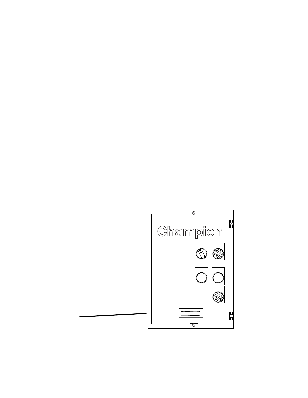
Complete the information below for quick reference.
Model Number Serial Number
Voltage and Phase
For Service:
The Source
502 Rotary Street.
Hampton, VA 23661
Phone: (757) 825-1600
1-800-497-2144
Fax: (757) 825-1202
website: www.thesource2000.com
email: Darlene Ehrenfried...........darlene@thesource2000.com
Ed Perales.........................eperrales@thesource2000.com
Kenny Height....................kheight@thesource2000.com
Larry Davis........................ldavis@thesource2000.com
Note: When calling to order parts, be sure to have the model number, serial number,
voltage and phase of your machine.
Machine Data Plate with
Model & Serial Number
located on the remote
control cabinet.
ON
OFF
START
POWER ON
BOOSTER
LOW TEMP
COPYRIGHT © 2004 by Champion Industries, Inc.
STOP

TECHNICAL PUBLICATION SHEET
TECHNICAL PUBLICATION SHEET
i

TECHNICAL MANUAL VALIDATION CERTIFICATE
TECHNICAL MANUAL VALIDATION CERTIFICATE
ii

APPROVAL AND PROCUREMENT RECORD
APPROVAL AND PROCUREMENT RECORD
iii

TECHNICAL MANUAL DEFICIENCY/EVALUATION REPORT (TMDER)
TECHNICAL MANUAL
DEFICIENCY/EVALUATION REPORT (TMDER)
(Form - NAVSEA 9086/10, REV. 6/85)
iv
REVISION RECORD
REVISION RECORD
Revision Revised Serial Number Comments
Date Pages Effectivity
4/29/98 All 90922 First Issue of Manual and replacement
parts lists
3/16/00 All J1050 Added electric tank heat to and
revised chain tensioner
3/9/01 58-59 J1051 Added end panels, front panels,
revised leg assy
3/9/01 60-61 J1051 Revised tank fill piping assy
3/9/01 62-63 J1051 Revised final rinse piping assy
3/9/01 66a-67a J1051 Revised track and guide assy
3/9/01 68a-69a J1051 Revised chain tension assy
3/9/01 70-71 J1051 Added end panel
3/9/01 86-87 J1051 Revised drain assy
3/9/01 90-91 J1050 Revised control cabinet
3/9/01 90a-90b J1051 Revised control cabinet
3/9/01 94-102 J1080 Added MRAN 90°
3/9/01 104-107 J1080 Added CH-60 Electric Booster
(For USS RAmage Only)
2/27/02 61,63 J1534 Added new vacuum breakers and kits
2/27/02 71 Replaced P/N's 112606 and 112607
with new part numbers 113398 and
113399.
4/8/02 102 Corrected spacer number for bubble 16
to 15.
103 Corrected part number 111064 to
111603 and 111605.
Corrected motor clamp from 314351 to
325622.
4/30/02 71 Replaced part number 112608 and 112783
with 110164.
Added V-belt 100795.
7/31/02 67, 67a J1616 Replaced part number 112708 with part
part numbers 900840 and 113509.
1/20/03 Front Cover Added APL numbers.
1/21/03 10,11 Corrected connection points from 3/4"
to 1/2" on hot water supply lines to
dishwasher connections.
1/23/03 20 Added prime switches to drawing and
control functions.
v
REVISION RECORD
REVISION RECORD (CONT.)
Revision Revised Serial Number Comments
Date Pages Effectivity
1/23/03 88, 89 J1698 Added P/N 109069 control thermostat.
6/23/03 91, 91a Revised part number for selector switch.
8/13/03 59 J1589 Revised P/N 317331 to 325351.
8/13/03 60, 63 Revised plastic style vacuum breakers
8/14/03 85 J1332 Revised P/N 111841 to 112379 and
8/14/03 92-93,92a-93a Inserted new replacement kits for
with bronze style.
112338 pump flange with gasket.
92b-93b selector switches, pushbuttons, lighted
switches
8/14/03 93,93a,93b Replaced Furance (Siemens) overloads
with Telemecanique (Square D) .
11/6/03 11, 13, 14-16, J1872 Insert new junction box location and
21 installation information.
11/6/03 76b, 77b J1872 Inserted new pages for terminal block
and strip drawing and parts.
11/06/03 82a, 83a J1872 Inserted new pages for wash and rinse
tank junction boxes drawings and parts.
11/06/03 J1872 Inserted new schematics and intercon-
nection drawings.
10/13/04 58, 59 J1921 Inserted additional curtain and curtain
rods in between wash and rinse tanks.
3/16/05 101 Corrected part number for item 8 from
208386 to 202381. Inserted note for
crank direction.
vi

THIS PAGE
INTENTIONALLY
LEFT BLANK
vii
SAFETY SUMMARY
SAFETY SUMMARY
Safety Symbols
• The following symbols appear throughout this manual alerting you to potential hazards.
Statements associated with each symbol are printed in italics.
WARNING:
Warning statements indicate any condition or practice that
could result in personal injury or possible loss of life.
CAUTION:
!
Caution statements indicate any condition or practice which,
if not strictly observed or remedied, could result in damage to
or destruction of the dishwasher.
NOTE:
Note statements indicate any condition or practice which,
if observed, will help in the safe completion of a task.
General Safety Rules
• The following general safety rules must be observed in addition to the specific cautions and warnings
presented in this manual.
• Your Champion dishwasher is a heated machine using very hot water to clean and sanitize a variety of
wares. Machine surfaces and wares become hot during and immediately following normal operations.
Consult your supervisor and wear protective gear as directed to avoid possible injury.
• Your dishwasher contains moving conveyor parts.
Use caution when working around the dishwasher especially when loading or unloading wares.
• Operators must NOT bypass a safety interlock or control to operate the dishwasher.
• The service and maintenance instructions contained in this manual are intended for qualified service
personnel. These instructions assume that you are trained in basic electricity and mechanical theory. If
you are not a trained technician, then do not attempt to adjust or repair the dishwasher as serious
personal injury or damage to the dishwasher may result.
viii

SAFETY SUMMARY
Warning and Caution Statement Listing
• The following listing gives the page number and text of all the warning and caution statements that
appear in this manual.
Warning Statements
Pg. 8- The installation of this unit must conform to local codes or, in the absence of local codes, to the National
Electrical Code and all National Codes governing plumbing, sanitation, safety and good trade practices.
Pg. 10- The installation of water supplies must conform to local codes or, in the absence of local code, all National
Codes governing plumbing, sanitation, safety and good trade practices.
Pg. 10- The installation of steam supplies must conform to local codes or, in the absence of local code, all National
Codes governing plumbing, sanitation, safety and good trade practices.
Pg. 12- The installation of drains must conform to local codes or, in the absence of local code, all National Codes
governing plumbing, sanitation, safety and good trade practices.
Pg. 12- The installation of ventilation must conform to local codes or, in the absence of local code, all National Codes
governing plumbing, sanitation, safety and good trade practices.
Pg. 13- The installation of electrical supplies and controls must conform to local codes or, in the absence of local
codes, the National Electrical Code and good trade practices.
Pg. 13- Dangerous voltages are present at the local electrical distribution system.
Dangerous voltages are present at the dishwasher when it is connected to the local electrical distribution
system.
Pg. 13- When working on the dishwasher, disconnect the electric service and place a red tag at the disconnect switch
to indicate work is being done on that circuit.
Pg. 14- The installation of electrical supplies and controls must conform to local codes or, in the absence of local
codes, the National Electrical Code and good trade practices.
Pg. 14- Dangerous voltages are present at the local electrical distribution system.
Dangerous voltages are present at the dishwasher when it is connected to the local electrical distribution
system.
Pg. 14- When working on the dishwasher, disconnect the electric service and place a red tag at the disconnect switch
to indicate work is being done on that circuit.
Pg. 24- Dangerous voltages are present at the local electrical distribution system.
Dangerous voltages are present at the dishwasher when it is connected to the local electrical distribution
system.
Pg. 24- When working on the dishwasher, disconnect the electric service and place a red tag at the disconnect switch
to indicate work is being done on that circuit.
Pg. 25- Perform the following checks before placing the machine into service for normal operation.
Pg. 25- Never bypass a safety device in order to operate the dishwasher for normal operation.
Pg. 26- The conveyor drive contains moving parts.
Use caution when working around the conveyor drive assembly.
Pg. 27- Perform the following checks before placing the machine into service for normal operation.
ix

SAFETY SUMMARY
SAFETY SUMMARY (Cont.)
Warning Statements (Cont.)
Pg. 27- Never bypass a safety device in order to operate the dishwasher for normal operation.
Pg. 28- Dishwasher surfaces, dishracks and wares become hot during and immediately after washing operations.
Wear protective gear per your supervisor's directions.
Pg. 29- Dishwasher surfaces, dishracks and wares become hot during and immediately after washing operations.
Wear protective gear per your supervisor's directions.
Pg. 32- Deliming solutions or other acids must not come in contact with household bleach (sodium hypochlorite) or
any chemicals containing chlorine, iodine, bromine, or fluorine.
Mixing will cause hazardous gases to form.
Skin contact with deliming solutions can cause severe irritation and possible chemical burns.
Pg. 32- Consult your chemical supplier for an appropriate deliming solution, protective gear and safety procedures.
Pg. 33- When working on the dishwasher, disconnect the electric service and place a red tag at the disconnect switch
to indicate work is being done on that circuit.
Pg. 34- When working on the dishwasher, disconnect the electric service and place a red tag at the disconnect switch
to indicate work is being done on that circuit.
Pg. 35- Do not lubricate the stainless steel conveyor chain or shaft bearings inside the dishwasher wash and power
rinse tanks.
Pg. 36- The conveyor drive contains moving parts.
Use caution when working around the conveyor drive assembly.
Pg. 37- When working on the dishwasher, disconnect the electric service and place a red tag at the disconnect switch
to indicate work is being done on that circuit
Pg. 40- When repairing a circuit, disconnect the power at the main service disconnect switch and place a red tag at
the disconnect switch to indicate that work is being performed on the circuit.
Pg. 40- Use Extreme Caution when performing tests on energized circuits.
Pg. 40- The conveyor drive contains moving parts. Use caution when working around the conveyor drive assembly.
x

SAFETY SUMMARY
Caution Statements
Pg. 5- Check piping mounted underneath dishwasher before lifting to avoid damaging the machine.
Pg. 8- Check piping mounted underneath dishwasher before lifting to avoid damaging the machine.
Pg. 21- Perform the following checks before placing the machine into service.
Pg. 31- Do not hose down the exterior of the machine with water.
Pg. 33- Only qualified service personnel should perform preventive maintenance on the dishwasher.
Pg. 34- Only qualified service personnel should perform preventive maintenance on the dishwasher.
Pg. 36- Only qualified service personnel should perform preventive maintenance on the dishwasher.
Pg. 40- Only qualified service personnel should perform adjustments and repairs to the dishwasher.
xi

LIMITED WARRANTY
LIMITED WARRANTY
Champion Industries Inc. (herein referred to as Champion), P.O. Box 4149, Winston-Salem, North Carolina 27115,
and P.O. Box 301, 2674 N. Service Road, Jordan Station, Canada, L0R 1S0, warrants machines, and parts, as set out
below.
Warranty of Machines: Champion warrants all new machines of its manufacture bearing the name
"Champion" and installed within the United States and Canada to be free from defects in material and workmanship for a period of one (1) year after the date of installation or fifteen (15) months after the date of shipment by
Champion, whichever occurs first. [See below for special provisions relating to glasswashers.] The warranty
registration card must be returned to Champion within ten (10) days after installation. If warranty card is not
returned to Champion within such period, the warranty will expire after one year from the date of shipment.
Champion will not assume any responsibility for extra costs for installation in any area where there are
jurisdictional problems with local trades or unions.
If a defect in workmanship or material is found to exist within the warranty period, Champion, at its election,
will either repair or replace the defective machine or accept return of the machine for full credit; provided, how
ever, as to glasswashers, Champion's obligation with respect to labor associated with any repairs shall end
(a) 120 days after shipment, or (b) 90 days after installation, whichever occurs first. In the event that Champion
elects to repair, the labor and work to be performed in connection with the warranty shall be done during regular
working hours by a Champion authorized service technician. Defective parts become the property of Champion.
Use of replacement parts not authorized by Champion will relieve Champion of all further liability in connection
with its warranty. In no event will Champion's warranty obligation exceed Champion's charge for the machine.
The following are not covered by Champion's warranty:
a. Lighting of gas pilots or burners.
b. Cleaning of gas lines.
c. Replacement of fuses or resetting of overload breakers.
d. Adjustment of thermostats.
e. Adjustment of clutches.
f. Opening or closing of utility supply valves or switching of electrical supply current.
g. Cleaning of valves, strainers, screens, nozzles, or spray pipes.
h. Performance of regular maintenance and cleaning as outlined in operator’s guide.
i. Damages resulting from water conditions, accidents, alterations, improper use, abuse,
tampering, improper installation, or failure to follow maintenance and operation procedures.
j. Wear on Pulper cutter blocks, pulse vanes, and auger brush.
Examples of the defects not covered by warranty include, but are not limited to: (1) Damage to the exterior or
interior finish as a result of the above, (2) Use with utility service other than that designated on the rating plate,
(3) Improper connection to utility service, (4) Inadequate or excessive water pressure, (5) Corrosion from
chemicals dispensed in excess of recommended concentrations, (6) Failure of electrical components due to
connection of chemical dispensing equipment installed by others, (7) Leaks or damage resulting from such
leaks caused by the installer, including those at machine table connections or by connection of chemical
dispensing equipment installed by others, (8) Failure to comply with local building codes, (9) Damage caused by
labor dispute.
Warranty of Parts: Champion warrants all new machine parts produced or authorized by Champion to be free
from defects in material and workmanship for a period of 90 days from date of invoice. If any defect in
material and workmanship is found to exist within the warranty period Champion will replace the defective
part without charge.
DISCLAIMER OF WARRANTIES AND LIMITATIONS OF LIABILITY. CHAMPION'S WARRANTY
IS ONLY TO THE EXTENT REFLECTED ABOVE. CHAMPION MAKES NO OTHER WARRANTIES,
EXPRESS OR IMPLIED, INCLUDING, BUT NOT LIMITED TO, ANY WARRANTY OF
MERCHANTABILITY, OR FITNESS OF PURPOSE. CHAMPION SHALL NOT BE LIABLE FOR
INCIDENTAL OR CONSEQUENTIAL DAMAGES. THE REMEDIES SET OUT ABOVE ARE
THE EXCLUSIVE REMEDIES FOR ANY DEFECTS FOUND TO EXIST IN CHAMPION DISHWASHING
MACHINES AND CHAMPION PARTS, AND ALL OTHER REMEDIES ARE EXCLUDED,
INCLUDING ANY LIABILITY FOR INCIDENTALS OR CONSEQUENTIAL DAMAGES.
xii
Champion does not authorize any other person, including persons who deal in Champion dishwashing
machines to change this warranty or create any other obligation in connection with Champion Dishwashing Machines.

TABLE OF CONTENTS
TABLE OF CONTENTS
Revision Record .......................................................................................................... v
Safety Summary .......................................................................................................... ix-xi
Limited Warranty ......................................................................................................... xii
PART 1: GENERAL SPECIFICATIONS........................................................
1.1 About this Manual ............................................................................................... 1
1.2 Model Numbers ................................................................................................... 1
1.3 Standard Equipment, Options and Accessories ................................................... 2
1.4 Dimensions, Capacities, Ventilation, and Utilities............................................... 3
1.5 Electrical Power Requirements ............................................................................ 4
PART 2: INSTALLATION ..............................................................................
2.1 Unpack the Dishwasher ....................................................................................... 5
2.2 Disassembly ......................................................................................................... 6
2.3 Reassembly .......................................................................................................... 7
2.4 Permanent Placement ........................................................................................... 8
2.5 Connections between the dishwasher and booster ............................................... 8
2.6 Water Connections .............................................................................................. 10
2.7 Steam and Condensate Connections (Steam heat only) ....................................... 10
2.8 Drain Connections ............................................................................................... 12
2.9 Ventilation Connections ....................................................................................... 12
2.10 Electrical Connections ......................................................................................... 13
2.11 Electrical Tank Heat Connections (Electric heat only) ........................................ 14
2.12 Chemical Connections ......................................................................................... 16
1
5
PART 3: OPERATION ...................................................................................
3.1 Theory of Operation ............................................................................................. 19
3.2 Description of Operator Controls and Indicators ................................................. 20
3.2.1 Remote Control Cabinet ............................................................................ 20
3.2.2 Dishwasher and Booster ............................................................................ 21
3.3 Start-up Procedure ............................................................................................... 23
3.4 Safety and Operation Checks ............................................................................... 25
3.5 Shutdown Procedure ............................................................................................ 29
3.6 Operation Summary ............................................................................................. 30
19
xiii

TABLE OF CONTENTS
PART 4: CLEANING and MAINTENANCE ...............................................
4.1 Introduction ....................................................................................................... 31
4.2 Daily Cleaning Schedules ................................................................................. 31
4.3 Deliming Schedule ............................................................................................ 32
4.4 Preventive Maintenance Schedules................................................................... 33
4.5 Lubrication Schedules....................................................................................... 35
PART 5: BASIC SERVICE .........................................................................
5.1 Introduction
5.2 General Troubleshooting................................................................................... 38
5.3 Component Repair and Replacement................................................................ 40
5.3.1 Pressure Reducing Valve (PRV) Adjustment ....................................... 40
5.3.2 Water Line Strainers ............................................................................ 41
5.3.3 Vacuum Breaker Repair ....................................................................... 41
5.3.4 Water Solenoid Valve Repair ............................................................... 41
5.3.5 Float Switch Replacement ................................................................... 42
5.3.6 Drain Valve and Overflow Assembly .................................................. 42
5.3.7 Thermometer Replacement .................................................................. 42
5.3.8 Tank Heat Thermostat Adjustment and Replacement.......................... 43
5.3.9 Steam Booster Thermostat Adjustment and Replacement ................... 43
5.3.10 Steam Solenoid Valve Repair .............................................................. 44
5.3.11 Steam Trap Repair ............................................................................... 45
5.3.12 Steam Booster Service ......................................................................... 45
5.3.13 Wash Manifold Restrictor Adjustment................................................. 47
5.3.14 Pump Seal Replacement ...................................................................... 47
5.3.15 Rinse Saver Assembly Repair .............................................................. 48
5.3.16 Conveyor Chain Take-up Assembly Adjustment ................................. 48
5.3.17 Take-up Bearing Replacement ............................................................. 49
5.3.18 Drive Shaft Bearing and Seal Replacement......................................... 49
5.3.19 Door Safety Switch Replacement ........................................................ 50
5.3.20 Control Circuit Explanation ................................................................. 50
5.3.21 Control Cabinet Fuse Replacement ..................................................... 54
5.3.22 Motor Overload Adjustment and Replacement ................................... 54
5.3.23 Timer Settings ...................................................................................... 55
5.3.24 Control Cabinet Pilot Light Bulb Replacement ................................... 55
31
37
xiv

TABLE OF CONTENTS
PART 6: REPLACEMENT PARTS ................................................................
6.1 Introduction .......................................................................................................... 57
6.2 Parts Parts Procurement ....................................................................................... 57
PART 7: ELECTRICAL SCHEMATICS .........................................................
PART 8: SPECIAL INSERTS ........................................................................
57
111
119
LIST OF FIGURES
Figure 2.1 – Disassembly ............................................................................................... 6
Figure 2.2 – Connections Between Dishwasher and Steam Booster.............................. 9
Figure 2.3 – Utility Connections .................................................................................... 11
Figure 2.4 – Remote Control Cabinet Tank Heat Connections ...................................... 14
Figure 2.5 – Tank Heater Conduit Routing .................................................................... 15
Figure 2.6 – Remote Control Cabinet............................................................................. 17
Figure 3.1 – Operator Controls Remote Control Cabinet............................................... 20
Figure 3.2 – Controls and Indicators Dishwasher and Booster ...................................... 21
Figure 3.3 – Conveyor Jam Switch Check ..................................................................... 26
Figure 3.4 – Curtain Placement ...................................................................................... 30
Figure 3.5 – Spray Arm Assembly ................................................................................. 30
Figure 4.1 – Never Lubricate These Points .................................................................... 35
Figure 4.2 – Conveyor Gearbox and Drive Chain Lubrication ...................................... 36
Figure 6.1 – Vents, Curtains, Doors, Panels, Scrap Screens, and Water Level Gauges . 58
Figure 6.2 – Tank Fill Assembly and Temperature Gauges............................................ 60
Figure 6.3 – Final Rinse Piping Assembly ..................................................................... 62
Figure 6.4 – Track Assembly.......................................................................................... 66
Figure 6.5 – Conveyor Shafts, Chains, Bearings, and Guides (Prior to S/N J1050) ...... 68
Figure 6.5a — Conveyor Shafts, Chains, Bearings, and Guides (
Figure 6.6 – Conveyor Chain Take-Up Assembly (Prior to S/N J1050) ........................ 70
Figure 6.6a – Conveyor Chain Take-Up Assembly (For S/N J1050 and above) ................... 70a
Figure 6.7 – Conveyor Drive Assembly ......................................................................... 72
Figure 6.8 – Rinse Saver Assembly ................................................................................ 74
Figure 6.9 – Steam Coil Assembly ................................................................................. 76
Figure 6.9a — Electric Tank Heat (For machines with S/N J1050 to JXXXX) ................ 76a
Figure 6.9b — Electric Tank Heat (For Machines beginning with S/N JXXXX and above) 76b
Figure 6.10 – Tank Steam Piping with Booster ................................................................ 78
For S/N J1050 and above) 68a
xv

TABLE OF CONTENTS
Figure 6.11 – Tank Steam Piping with Booster ................................................................ 80
Figure 6.12 –
Figure 6.12a— Junction Boxes, Float Switches, Door Switches, and Thermostats (After JXXXX) ........... 82a
Figure 6.13 – Pump Assembly.......................................................................................... 84
Figure 6.14 – Wash Spray System (R-L Machine Shown) ............................................... 86
Figure 6.15 – Drain and Overflow Assembly................................................................... 88
Figure 6.16 – Steam Booster and Steam Piping Assembly .............................................. 90
Figure 6.17 – Steam Remote Control Cabinet (Prior to S/N J1050) ................................ 92
Figure 6.17a — Electric Remote Control Cabinet (For S/N J1050 and above) ................... 92a
Figure 6.17b— Steam or Electric Control Cabinet (For S/N J1080 and above) ................. 92b
Figure 6.18 – Dishracks and PRV .................................................................................... 94
Figure 6.19 — MRAN 90° Guides ..................................................................................... 96
Figure 6.20 — MRAN 90° Pawl Bar ................................................................................. 98
Figure 6.21 — MRAN 90° Table and Drain Assembly ...................................................... 100
Figure 6.22 — MRAN 90° Base Assembly........................................................................ 102
Figure 6.23 — MRAN 90° Drive and Motor Assembly .................................................... 104
Figure 6.24 — CH-60 Electric Booster Piping (For USS Ramage Only) .......................... 106
Figure 6.25 — CH-60 Electric Booster Piping (For USS Ramage Only) .......................... 108
Junction Boxes, Float Switches, Door Switches, and Thermostats (Prior to JXXXX) ........ 82
LIST OF FIGURES
(CONT.)
LIST OF TABLES
Table 3.1 – Controls and Indicators Remote Control Cabinet ...................................... 20
Table 3.2 – Controls and Indicators Dishwasher and booster ....................................... 22
xvi

Part 1: GENERAL SPECIFICATIONS
PART 1: GENERAL SPECIFICATIONS
1.1 About this Manual
All information, illustrations and specifications contained in this manual are based upon the
latest product information available at the time of publication. Champion constantly improves
its products and reserves the right to make changes at any time or to change specifications or
design without notice and without incurring any obligation.
Manual Organization
This manual is divided into seven parts:
♦ Part 1, General Specifications, introduces this manual and the dishwasher in general.
♦ Part 2, Installation, discusses the installation of the dishwasher and describes the
connection of utilities and services.
♦ Part 3, Operation, discusses theory of operation, operator controls, initial start up and
shutdown procedures.
♦ Part 4, Cleaning and Maintenance, discusses lubrication, preventive maintenance,
cleaning and deliming.
♦ Part 5, Basic Service, discusses basic troubleshooting, service procedures, and corrective
maintenance.
♦ Part 6, Replacement Parts, discusses replacement parts procurement and provides parts
diagrams and
parts lists.
♦ Part 7, Electrical Schematics, contains the dishwasher electrical schematic.
1.2 Model Numbers
USN-72
The USN-72 series is a two-tank, high temperature (180°F/82°C rinse), sanitizing rack
conveyor dishwasher. This model features electric or steam heat and external booster.
The USN-72 is available in either right to left or left to right conveyor operation.
The USN-72 comes in the following models:
250-USN-72: 250 racks /hour
185-USN-72: 185 racks /hour
135-USN-72: 135 racks /hour
85-USN-72: 85 racks /hour
60-USN-72: 60 racks /hour
1

Part 1: GENERAL SPECIFICATIONS
1.3 Standard Equipment
♦ Modular construction for easy installation
♦ Deep tank design to withstand 15° list without water slosh
♦ Heavy duty dual chain drive with rear lugs
♦ Lift-out doors
♦ Open construction without panels for easy service and cleaning
♦ Exhaust vent extended to table level on each end
♦ All 304 stainless steel construction
♦ Flanged feet for deck mounting
♦ Interchangeable upper and lower spray arms
♦ 2 HP drip proof pump/motor assemblies
♦ 1/4 HP conveyor drive motor
♦ Make up water with constant flow during operation
♦ Dishwasher shutdown below 180°F final rinse temperature via thermal switch
♦ Manual fill for wash/rinse tank with water level sight gauges
♦ Manual Ball valve drain in each tank plumbed to a common connection
♦ Steam piping without threaded joints in tanks
♦ Remote mounted NEMA 4X control cabinet
♦ Common utility connections
♦ 440/60/3 power supply
♦ 120VAC control circuit
♦ Steam coil or electric tank heat
♦ Detergent/Chemical connection provisions
♦ Float switch low water heat protection with 5 second delay
♦ Door safety switches
♦ Conveyor jam limit switch
♦ Easily removable scrap screens
♦ Rinse saver device for water conservation
♦ Dishracks (peg rack and flat bottom rack)
Options and Accessories
♦ External steam booster heater 40° or 70° rise (specified at time of order)
♦ External electric booster heater 40° or 70° rise (specified at time of order)
(stainless steel, completely interplumbed and interwired)
♦ Right to left or left to right conveyor operation (specified at time of order)
♦ Choice of conveyor speed (250, 185, 135, 85, or 60 racks per hour)
(specified at time of order)
♦ Power unloader
♦ 90° motorized rack advance conveyor (specify load or unload)
♦ Dishracks - dish or open (specify type)
♦ Table limit switch, unmounted (recommended on all conveyor installations)
2
Part 1: GENERAL SPECIFICATIONS
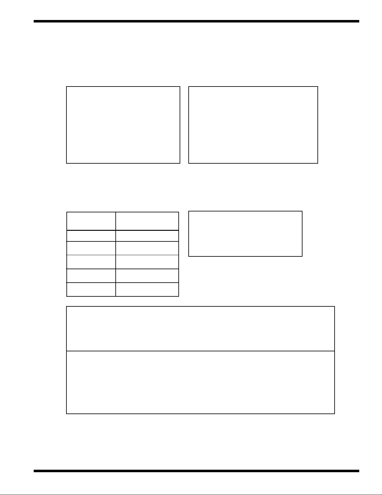
1.4 Dimensions, Capacities, Ventilation, and Utilities
Dimensions
Height 56.188 inches (w/o piping)
Width 25.0 inches
Length 72.0 inches (w/o vents)
Volume crated 125 cu. ft.
Shipping weight crated 1000 lbs.
Weight uncrated 850 lbs.
Rack Capacity
and Conveyor Speed
Based on standard 20" X 20"
dishracks manually loaded
Rack Capacity
(racks/hr)
60 1.67
85 2.36
135 3.75
Conveyor Speed
(ft/min.)
Capacities
Wash tank 22.0 gallons
Rinse tank 22.0 gallons
Final rinse flow 300.0 gal/hr @ 20 psig
Wash make up 60.0 gal/hr @ 20 psig
Total water usage 360.0 gal/hr
Ventilation (Minimum)
Load end 200 CFM @ 1/4"S.P
Unload end 400 CFM @ 1/4"S.P.
185 5.14
250 6.94
Utilities
Hot water: 3/4" NPT 140°F hot water connection @ 20-22 psig flow pressure
Drain: 1-1/2" NPT drain connection @ 15 gal/min maximum flow rate.
Electric: 440/60/3
Steam: 1-1/2" NPT steam connection (for machine and booster) @ 15-30 psig flow pres.
Tank heat consumption 150 lbs./hr.
70°R Steam booster consumption 255 lbs./hr.
Condensate: 3/4" NPT machine return to boiler (no back pressure)
3

Part 1: GENERAL SPECIFICATIONS
1.5 Electrical Power Requirements
1.5.1 Power Requirements for Steam Heat
Machine Full Load Amps 6.9A
Operating Currents (440V/60/3 Supply)
Steam Heated
Wash motor 2.7 Amps
Rinse motor 2.7 Amps
Drive motor 0.4 Amps
Control Circuit 1.1 Amps
Circuit Voltage Booster Rise Machine Power Requirement
Hz/Ph (Steam) Full Load Amps (125% Service Factor)
Motor/Control 440/60/3 70° 6.9 Amps 9.0 Amps
1.5.2 Power Requirements for Electric Heat
Machine Full Load Amps 6.9A
Operating Currents (440V/60/3 Supply)
Wash motor 2.7 Amps
Rinse motor 2.7 Amps
Drive motor 0.4 Amps
Control Circuit 1.1 Amps
Each heat circuit has a separate power source.
Heat Voltage KW Amps Power Requirement
Circuit Hz/Ph (Electric) Full Load (125% Service Factor)
Wash
tank heat 440/60/3 20KW 27 Amps 33 Amps
Power Rinse
tank heat 440/60/3 30KW 40 Amps 50 Amps
Final Rinse
Booster (40°rise)
(One cannister)
440/60/3 37.8KW 49.6 Amps 62 Amps
Final Rinse
Booster (70°rise)
(Two cannisters)
Cannister 1 440/60/3 32.8KW 43 Amps 53.8 Amps
Cannister 2 440/60/3 32.8KW 43 Amps 53.8 Amps
Total KW for 70°rise is 65.6 KW
4

PART 2: INSTALLATION
In This Part—
• Unpacking the dishwasher
• Disassembling the dishwasher to move through hatches
• Making Utility Connections
2.1 Unpack the Dishwasher
NOTE:
The installation of your dishwasher must meet all applicable
health and safety codes and conform to good trade practice.
Part 2: INSTALLATION
Your USN-72 was completely assembled, inspected, and thoroughly tested at our factory
before shipment to your installation site.
• The dishwasher with vents and booster are shipped on a single pallet.
• The booster is disconnected from the dishwasher.
• The remote mounted control cabinet is shipped in a separate carton.
Perform the following steps to unpack the dishwasher:
1. Remove protective wrap and hold-downs from the pallet.
2. Inspect for any shipping damage. If damage is found, save the packing material
and contact the carrier immediately.
3. Check the interior of the dishwasher for the following items stowed inside:
- 1 set of flanged feet
- 1 set of dishracks
- Warranty information packet
CAUTION:
!
Check piping mounted underneath dishwasher before lifting, to avoid damaging the
machine.
4. Remove the dishwasher from the skid.
NOTE:
If you need to move the dishwasher through shipboard hatches, refer to Part 2.2,
Disassembly, on the next page.
5. Move the dishwasher to its permanent location if no disassembly is
required. Refer to Part 2.4, Permanent Placement.
5
Part 2: INSTALLATION
2.2 Disassembly
The USN-72 will require partial disassembly to move it through a standard 26" x 66" hatch.
Go to Part 2.4, Permanent Placement, if disassembly is not required.
Perform the following steps to disassemble the dishwasher. Refer to Fig. 2.1 below.
1. Remove (7) 1/4-20 nuts and washers from each vent collar assembly.
Pull the vent collars off the machine.
2. Disconnect the union in the upper final rinse piping assembly.
3. Disconnect the union in the wash water makeup line.
Remove the upper final rinse piping assembly and the makeup line.
4. Inspect the fill piping on the top of the tanks
5. Remove (1) 1/2" locknut located inside the machine from each vertical fill pipe.
Remove the upper fill pipe assemblies.
6. Turn the conveyor chain tension adjusters until the conveyor chain is slack.
7. Locate the master links in the conveyor chain and remove.
Disconnect the chains and pull them to the chain adjuster in the wash tank.
8. Remove 1/4-20 hardware and U-clip protecting the inside tank joint.
9. Remove hardware securing outside front tank flange.
10. Remove the hardware joining the tank bases.
11. Disconnect the 1-1/2" drain line union underneath the dishwasher.
12. Disconnect the 1/2" steam condensate union.
13. Disconnect the 3/4" tank steam supply union
between the wash and rinse tanks.
14. Disconnect and mark the wiring and
conduit between the tanks.
15. Pull the wash and
rinse tanks apart.
16. Move the dishwasher
to its permanent
location.
17. Refer to Part 2.3,
Reassembly.
1
4
3
2
7
5
6
8
11
9
14
12
13
10
Figure 2.1
Disassembly
6

Part 2: INSTALLATION
2.3 Reassembly
Special Tools and Materials Required—
• Bubble level (3 ft.)
• Silicone sealant, (1) 12 fl. ounce tube, Dow Corning® RTV or comparable
• Plumber's sealing putty (Champion P/N 104889) or comparable
• Pipe thread sealant, Loctite® 565 or comparable
If you disassembled your dishwasher to move it through hatches as described in Part 2.2, then
follow the instructions in this part to reassemble your dishwasher. Go to Part 2.4, Permanent
Placement, if disassembly was not required for your dishwasher.
Perform the following steps to reassemble the dishwasher prior to permanent placement.
Refer to Fig. 2.1 on the preceding page.
1. Before moving the sections into position, inspect the location site to ensure the electrical,
plumbing, and ventilation services are provided in the correct locations. Compare the site
connections with the dishwasher to ensure they will match when the machine is set in its
permanent location.
2. Move the wash and rinse tanks in close proximity to each other in the direction
they will be installed.
3. Apply a 1/2" bead of silicone sealant on the face of all sides of the wash tank hood gasket.
4. Move the rinse tank closer to the wash tank and check the alignment of the bolt holes at the base
and around the tank hood.
5. Adjust the rinse tank adjustable legs to align the bolt holes.
6. BOLT THE HOOD SECTIONS FIRST.
Make sure the U-clip removed in Step 8, Part 2.2 is installed.
Start the bolts and tighten nuts hand tight.
7. Check the alignment of the 1-1/2" drain union underneath the machine. Adjust tanks as required.
8. Start the bolts and hand tighten the nuts to join the bases.
9. Connect the 1-1/2" drain union.
10. Tighten all bolts securely using a cross pattern to pull the tanks together evenly.
11. Reconnect the wiring and plumbing. Refer to Steps 12-14, Part 2.2 and Fig 2.1.
12. Pull the conveyor drive chains stored in the wash tank back to the rinse tank. Make sure
the drive chain with the dishrack lugs is positioned on the rear track. See Item 7, Fig.2.1.
13. Replace the drive chain master links and tighten the chain adjusters evenly. Proper chain tension
is achieved when the chain can be lifted off the track a maximum of 1-1/2".
14. Reinstall remaining plumbing using plumber's putty or thread sealant where required.
Refer to Steps 2-5, Part 2.2 and Fig.2.1
15. Position dishwasher in its permanent location.
16. Lift the dishwasher and replace the adjustable legs with the flanged mounting feet provided.
17. Level the dishwasher front to back and side to side by turning the adjustable feet.
Make sure the load and unload openings align with the table system height.
18. Reinstall the vent collars.
19. Go to Part 2.4, Permanent Placement.
7

Part 2: INSTALLATION
2.4 Permanent Placement
Refer to Part 2.2, Disassembly and Part 2.3, Reassembly if your dishwasher requires transport through
ship hatches, otherwise proceed with the instructions listed below.
Perform the following steps to place the dishwasher in its permanent location.
1. Before moving the sections into position, inspect the location site to ensure the electrical,
plumbing, and ventilation services are provided in the correct locations. Compare the site
connections with the dishwasher to ensure they will match when the machine is set in its
permanent location.
CAUTION:
!
Check piping mounted underneath dishwasher before lifting, to avoid damaging the machine.
2. Lift the dishwasher and replace the adjustable legs with the flanged mounting feet provided.
3. Position dishwasher in its permanent location.
4. Level the dishwasher front to back and side to side by turning the adjustable feet.
Make sure the load and unload openings align with the table system height.
5. Position the external booster heater at the unload end of the dishwasher.
Check alignment of common plumbing connections between booster and dishwasher.
6. Install deck plates, and bolt dishwasher and booster to deck per standard procedures.
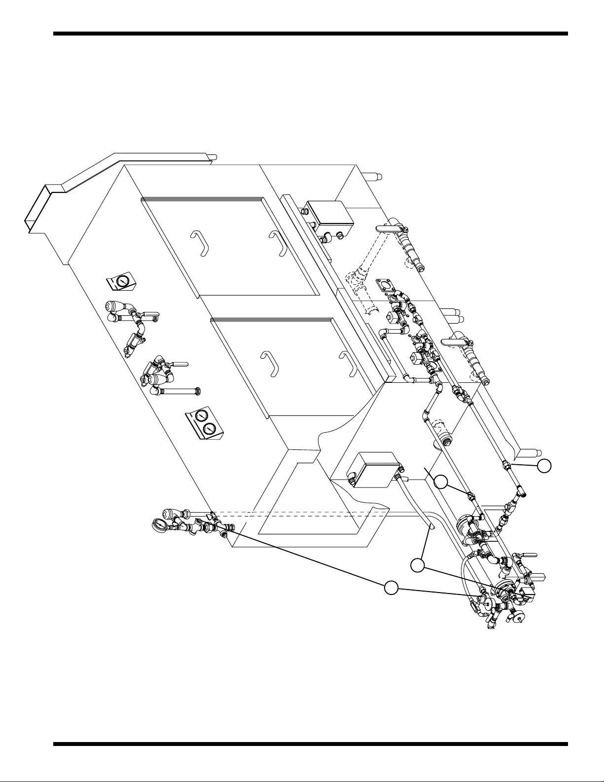
2.5 Connections between the dishwasher and booster
Refer to Figure 2.2 on the next page.
WARNING:
The installation of this unit must conform to local codes or, in the absence of local codes,
to the National Electrical Code and all National Codes governing plumbing, sanitation,
safety and good trade practices.
Connect the plumbing and electrical connections between the dishwasher and booster heater.
1. Connect the 1/2" condensate union from the dishwasher to the booster. (See No. 1, Fig. 2.2).
2. Connect the 3/4" steam union from the dishwasher to the booster. (See No. 2, Fig. 2.2).
3. Connect the 3/4" water line from the booster to the top of the dishwasher at the
vacuum breaker. (See No. 3, Fig. 2.2).
4. Pull the electrical conduit and harness from the junction box located on the lower
rear corner of the dishwasher to the booster junction box located on the lower left rear leg
of the booster stand. (See No. 1, Fig. 2.2).
5. Match the harness wire numbers to the booster junction box wiring.
8
Part 2: INSTALLATION
C
hamp
ion
C
hamp
ion
Figure 2.2
Connections Between
Dishwasher and Steam Booster
(Right to left model shown)
(Conduit/
3
line)
(3/4" water
(3/4" steam union)
2
Harness)
4
union)
(1/2" condensate
1
9
Part 2: INSTALLATION
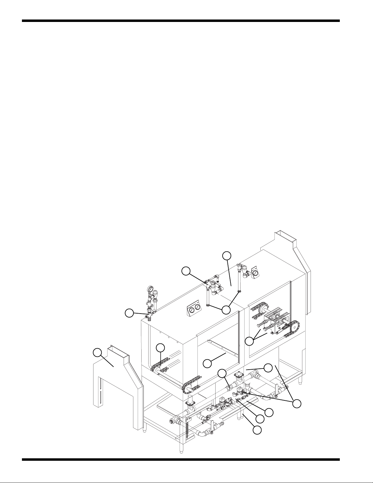
2.6 Water Connections
Perform the following steps to connect the water supply
Refer to Figure 2.3 on the next page.
WARNING:
The installation of water supplies must conform to local codes or, in the absence of local code,
all National Codes governing plumbing, sanitation, safety and good trade practices.
1. Connect a 3/4" NPT hot water supply line (110°F minimum) to the water inlet valve located
at the booster. (See No. 1, Fig. 2.3.)
2. Connect a 1/2" NPT hot water line (140°F minimum) to the water inlet valve located at the
top of the dishwasher. (See No. 2, Fig. 2.3.)
2.7 Steam and Condensate Connections (Steam heat only)
Perform the following steps to connect the steam supply and condensate return.
Refer to Figure 2.3 on the next page.
WARNING:
The installation of steam supplies must conform to local codes or, in the absence of local code,
all National Codes governing plumbing, sanitation, safety and good trade practices.
NOTE:
A manual shut-off valve for steam (supplied by others) should be installed in the supply lines
to allow for servicing of the machine. The shut-off valve should be the same size or larger
than the supply line.
1. Connect a 1-1/2" NPT steam supply line to the line strainer located at the booster.
(See No. 3, Fig 2.3)
2. Connect a 1" NPT steam condensate line to the tee fitting located at the booster.
Condensate must be gravity return to the boiler or to a pumping trap.
(See No. 4, Fig. 2.3)
10
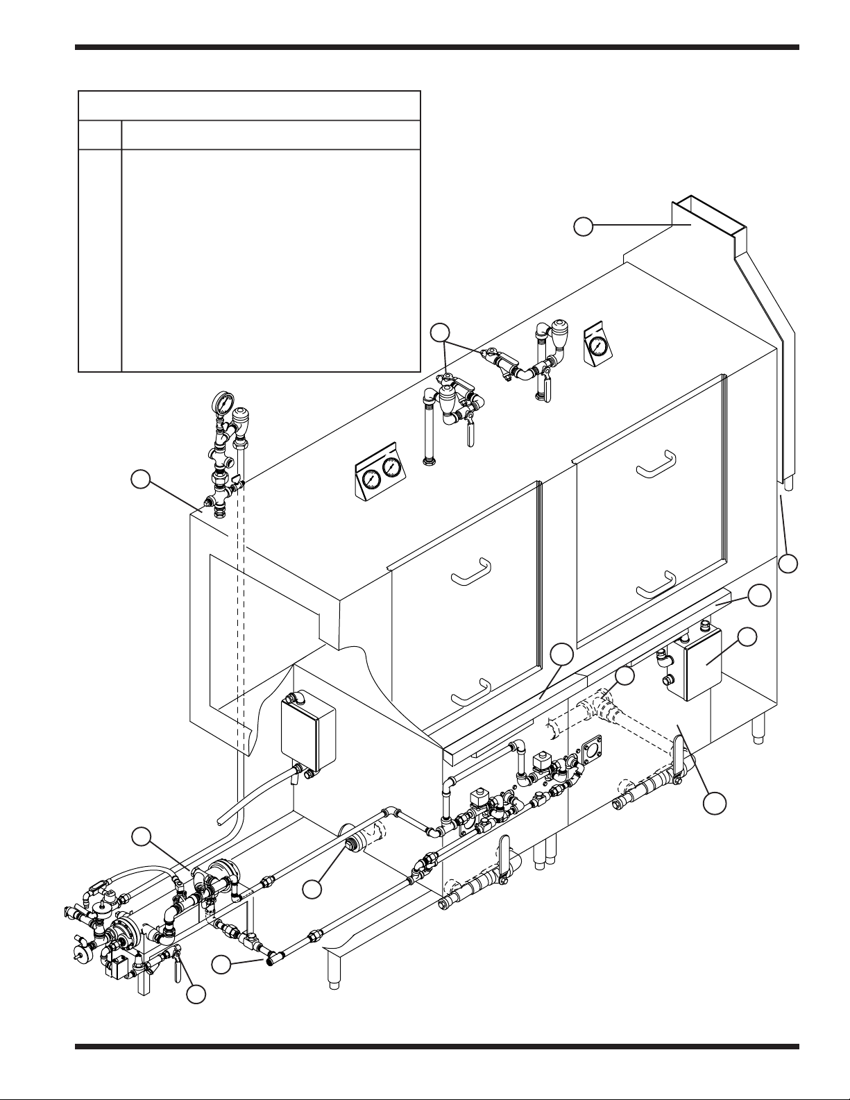
Utility Connection Points
No. Description
1 3/4" NPT hot water supply line for booster
2 1/2" NPT hot water supply line for dishwasher
3 1/2" NPT steam supply line
4 1/2" NPT steam condensate line
5 1-1/2" NPT drain line
6 1/2" NPT vent collar drain line
7 Dishwasher main electrical junction box prior
to S/N JXXXX
7A Wash/Rinse tank electrical junction box after
S/N JXXXX
8 11.13" x 3.87" vent collar connection
9 1/4" rinse aid injection point
10 Detergent injection point
Part 2: INSTALLATION
8
2
9
ion
hamp
C
6
ion
hamp
C
3
7A
5
10
7A
7
5
4
1
(Right to left model shown)
Figure 2.3
Utility Connections
11
Part 2: INSTALLATION
2.8 Drain Connections
Perform the following steps to connect the drain lines.
Refer to Figure 2.3 on the preceding page.
WARNING:
The installation of drains must conform to local codes or, in the absence of local code,
all National Codes governing plumbing, sanitation, safety and good trade practices.
1. Connect a 1-1/2" NPT drain line to the dishwasher. The machine drain is a level line so
connection can be made on either end by relocating the drain plug.
The drain line is located underneath the dishwasher. (See No. 5, Fig. 2.3, page 11.)
2. Connect 1/2" NPT drain lines to the load and unload vent collars, (2) connections per collar.
(See No. 6, Fig. 2.3, page 11.)
2.9 Ventilation Connections
Perform the following steps to connect the ventilation system
Refer to Figure 2.3 on the preceding page.
WARNING:
The installation of ventilation must conform to local codes or, in the absence of local code,
all National Codes governing plumbing, sanitation, safety and good trade practices.
1. Connect an exhaust duct to the load and unload vent collar located at each end of the dishwasher.
Inside dimensions of the vent collar connection are 11.13" x 3.87".
(See No. 8, Fig. 2.3, page 11).
2. The minimum vent capacities are given below:
Load end 200 CFM @ 1/4"S.P (minimum)
Unload end 400 CFM @ 1/4"S.P. (minimum)
12
 Loading...