

Champion 54KB, 44WS, KL44 General Manual
For machines beginning with serial no. 84000
thru 99999 and serial no. R1000 and above
Technical Manual
Single Tank
Rack Conveyor
with/without Prewash
With (FFPR26)
Basic With (PR22) With (PR36) 26" Front Feed
Model 22" Prewash 36" Prewash Prewash
44KB 44KPRB PR36/44KB FFPR26/44KB
54KB 54KPRB PR36/54KB FFPR26/54KB
44WS 66WS PR36/44WS FFPR26/44WS
KL44 KL66 PR36/KL44 FFPR26/KL44
Machine Serial No.
March, 2004 Manual P/N 112844 Rev. H
P.O. Box 4149 2674 N. Service Road
Winston-Salem, North Carolina 27115-4149 Jordan Station, Ontario, Canada L0R 1S0
336/661-1556 Fax: 336/661-1660 905/562-4195 Fax: 905/562-4618
www.championindustries.com
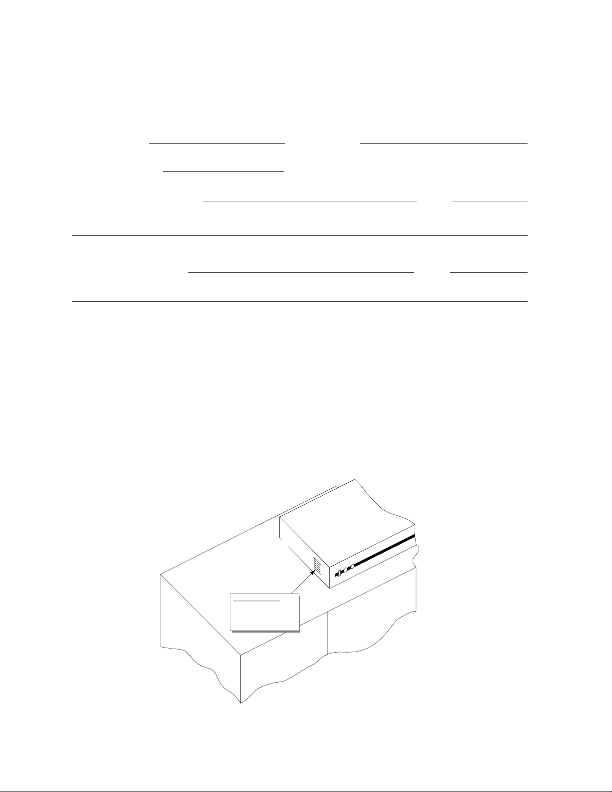
Complete the information below so it will be available for quick reference.
Machine Data Plate with
Model No., Serial No.,
Voltage and Phase is
located on the right or left
side of the Control Cabinet
Top of Machine
Control Cabinet
Left to Right
Model Shown
Model Number Serial Number
Voltage and Phase
Champion Service Agency Phone
Champion Parts Source Phone
Champion Service:
Champion (USA) Champion (Canada)
Phone: 1 (336) 661-1556 Phone: 1 (905) 562-4195
1 (800) 858-4477 1 (800) 263-5798
Fax: 1 (336) 661-1660 Fax: 1 (905) 562-4618
We strongly recommend that you Fax your orders.
NOTE: When calling to order parts, be sure to have the model number, serial number,
voltage and phase of your machine.
COPYRIGHT © 2004 by Champion Industries, Inc.
REVISIONS
Revision History
The revisions listed below cover machine design changes prior to the publication of this
manual, P/N 112844, dated June, 1998.
Revision Revised Serial Number Comments
Date Pages Effectivity
04/01/93 — 84565 Redesign of cradle, replaced cradle roller with slide
04/01/93 — 84545 Additon of stiffener to idle pump mechanism
04/01/93 — 84565 Redesign of wash system, addition of adjustable
restrictors
04/01/93 — — Removed water shock arrestor from the rinse piping
04/01/93 — — Repositioned PRV on rinse piping
04/01/93 — 84565 Redesign of final rinse pipes and nozzles
04/01/93 — 84565 Redesign of drain mechanism and filler panel
04/01/93 — 84565 Redesign of rinse saver switch
04/01/93 — 84545 Redesign and relocation of door safely switch
04/01/93 — 84565 Redesign of drain mechanism and overflow
04/01/93 — 84350 Change in booster to 63Kw
10/20/93 — 85331 Changed 63Kw element combination to (3) 9Kw &
(2) 18Kw in the electric booster tank
04/01/93 — 84350 Redesign of booster cabinet components
10/20/93 — 85261 Redesign of control cabinet using Furnas
components
09/02/94 — 86424 Replace SST rinse manifold with brass fittings
3/21/95 — 87001 Changed design of ON-OFF/circuit breaker switch,
new P/N 111980 issued
5/12/95 — 87150 Redesigned pump assemblies and changed impellers to
all stainless steel construction
9/28/95 — 87575 Redesign of booster to use 12Kw heaters
3/3/96 — 88124 Redesign of f inal rinse switch assembly
7/19/96 — 88503 Redesign of control cabinet terminal block
1/8/97 — 89120 Changed design of pump timer, new P/N 112351
3/5/97 — 89277 Redesign of wash system to debossed spray pipes
11/26/97 — 90513 Redesign of KL 44/66 final rinse assembly, cradle
and final rinse switch assembly
8/3/98 — 99999 Changed S/N format to R1000 and above
i

REVISIONS
Revision History
Revision Revised Serial Number Comments
Date Pages Effectivity
10/30/98 All 84000- Issue of new manual and new parts replacement lists
12/3/99 142,144 R1649 Added 7CR, 120VAC Hold-in relay to control cabinet
02/01/01 41,42 R1766 Changed pump valve P/N 111696 to 112380, Oring
02/01/01 68,69 R1529 Insert new piping for outside rinse with electric
02/01/01 72 R1529 Insert new piping for outside rinse with no electric
02/21/01 135,139,143 — Change part number 111642 to 108122
02/21/01 136,140,144,163,165 — Change part number 111826 to 111827
12/05/01 140,144 — Corrected descriptions on contactors
12/05/01 136,140,143,144 — Added Fuse size numbers to descriptions
01/02/02 69,73,77 R2426 Change vacuum breaker 3/4" P/N 104429 to 113222
01/02/02 81,85 R2426 Change vacuum breaker 1/2" P/N 100500 to 113220
01/02/02 70,74,78,82 R2562 Change vacuum breaker 1/4" P/N 107069 to 113218
01/02/02 69,73,77,81 R2346 Change Parker/Evans solenoid valve 1/4" P/N 109885
01/02/02 112,115,116 R2208 Added new table flange P/N 325492 and track stiffener
01/02/02 125 R1690, R1719 Added new water baffles 325159 and 325160
05/20/02 70,74,78,82,86 Added 900836 Kit* Repair, 1/4" & 1/2" Vacuum
02/05/03 41 — Replaced impellers with new part numbers.
02/05/03 133 — Replaced P/N 108391 with 113622.
02/05/03 139,143 — Replaced Furnace (Siemens) overloads with
7/22/03 69,70,73,74,77,78,81 –– Revised plastic style vacuum breakers with
7/23/03 133 –– Corrected part numbers on overlays.
3/11/04 45,47,97,99,101,103, R3285 Replaced 111090 with 113721 reed switch.
3/11/04 v –– Replaced B700933 revision N with revision O.
& above Supersedes previous manual P/N 110874 beginning
with date January 1989 thru June 1993.
circuit to maintain power to booster circuit.
P/N 111725 to gasket 112338, and Suction Flange
P/N 111841 to 112379.
booster (new figure & parts)
booster and with steam booster.
86,89,111,115
85,89,111,116 and 1/2" P/N 109886 to GC solenoid valve 1/2" P/N
113352 along with repair kit, coil and piping changes
P/N 325667
R2074, R2127
89,112,116 Breaker and 900837 Kit* Repair, 3/4" Vacuum Breaker
Telemecanique (Square D) overloads.
82,85,86,89,111,112,115 bronze style
105, 107, 108, 111
ii

CONTENTS
CONTENTS
Page
REVISION HISTORY ...................................................................................................................... i
WARRANTY .................................................................................................................................. vi
KEY COMPONENTS ...................................................................................................................... 1
INTRODUCTION .......................................................................................................................... 2
GENERAL........................................................................................................................................ 3
INSTALLATION ............................................................................................................................ 5
Unpacking .......................................................................................................................... 5
Electrical Connections ........................................................................................................ 5
Plumbing Connections ........................................................................................................ 6
Ventilation Connections ...................................................................................................... 6
Chemical Connections ........................................................................................................ 6
Curtain Locations ................................................................................................................ 7
Completing Installation ...................................................................................................... 7
OPERATION .................................................................................................................................... 8
MAINTENANCE ............................................................................................................................ 11
Maintenance Schedule ........................................................................................................ 11
Deliming .............................................................................................................................. 12
TROUBLESHOOTING .................................................................................................................. 13
ELECTRICAL SERVICE ................................................................................................................ 15
MECHANICAL SERVICE ..............................................................................................................23
TABLE LIMIT SWITCH INSTALLATION.................................................................................... 27
REPLACEMENT PARTS ................................................................................................................ 31
ELECTRICAL SCHEMATICS ...................................................................................................... 171
LIST OF FIGURES
Figure 1 — Fuse Blocks .............................................................................................................. 15
Figure 2 — Motor Overload ...................................................................................................... 15
Figure 3 — Pump Timer ..............................................................................................................16
Figure 4 — Dual Float Switch .................................................................................................... 17
Figure 5 — Tank Heat Thermostats ............................................................................................ 18
Figure 6 — Booster Thermostat Locations (Electric) ................................................................ 18
Figure 7 — Booster High Limit Thermostat (Electric) .............................................................. 18
Figure 8 — Front View Typical 40°F/22°C rise Booster, One Tank 38 Kw shown .................. 22
Figure 9 — Front View Typical 70°F/39°C rise Booster, Two Tank 63 Kw shown .................... 22
Figure 10 — Idle Pump Switch Assembly .................................................................................... 24
iii

CONTENTS
Figure 11 — Magnetic Switch and Magnet .................................................................................. 24
Figure 12 — Rinse-Saver Switch Mechanism .............................................................................. 24
Figure 13 — Crank Assembly........................................................................................................ 25
Figure 14 — Conveyor Drive Assembly ........................................................................................ 25
Figure 15 — View of Load End of Machine ................................................................................ 26
Figure 16 — Close-up View of Bearing Housing ........................................................................ 26
Figure 17 — Close-up View of Clutch Assembly.......................................................................... 26
Figure 18 — Conveyor Drive Assembly ........................................................................................ 32
Figure 19 — Track and Cradle Assembly (S/N 84565 and above except KL-44/66) .................. 34
Figure 19a — Track and Cradle Assembly (Prior to S/N 84565) .................................................. 35
Figure 20 — Track and Cradle Assembly (PR22, PR36) (All S/N’s)............................................ 36
Figure 21 — Track and Cradle Assembly (KL-44/66 Only) (S/N 90513 and above) .................. 38
Figure 22 — Motor and Pump Assembly (All S/N’s).................................................................... 40
Figure 23 — Idle Pump Mechanism (All S/N’s) .......................................................................... 44
Figure 24 — Idle Pump Switch (FFPR26 Only) (All S/N’s) ........................................................ 46
Figure 25 — Wash System Assembly (Prior to S/N 84565).......................................................... 48
Figure 26 — Wash System Assembly (PR22, FFPR26) (Prior to S/N 84565).............................. 50
Figure 27 — Wash System Assembly (PR36) (Prior to S/N 84565) ............................................ 52
Figure 28 — Wash System Assembly (S/N 84565 thru S/N 89276) ............................................ 54
Figure 29 — Wash System Assembly (PR22, FFPR26) (S/N 84565 thru S/N 89276) ................ 56
Figure 30 — Wash System Assembly (PR36) (S/N 84565 thru S/N 89276) ................................ 58
Figure 31 — Wash System Assembly (S/N 89277 and above)...................................................... 60
Figure 32 — Wash System Assembly (PR22, FFPR26) (S/N 89277 and above).......................... 62
Figure 33 — Wash System Assembly (PR36) (S/N 89277 and above) ........................................ 64
Figure 34 — Outside Rinse Piping with Electric Booster (Prior to R1529) ................................ 66
Figure 35 — Outside Rinse Piping with Electric Booster (After S/N R1530).............................. 68
Figure 36 — Fill and Outside Rinse Piping, w/No Booster or with Steam Booster (All S/N’s) .. 72
Figure 37 — Fill and Outside Rinse Piping w/ No Booster, (KL-44/66) (All S/N’s) .................. 76
Figure 38 — Fill and Outside Rinse Piping 44WS w/Electric Booster (S/N 82305 and above) .. 80
Figure 39 — Fill and Outside Rinse Piping 44WS – No Booster and Steam Booster
Figure 40 — Cold Water Thermostat for Prewash Option (All S/N’s) ........................................ 88
Figure 41 — Inside Rinse Piping and Rinse Drain-Off (KL-44/66 Only) (S/N 90513 and above) 90
Figure 42 — Inside Rinse Piping and Rinse Drain-Off (KB, WS, KL) (S/N 87575 and above).. 92
Figure 43 — Inside Rinse Piping & Rinse Drain-Off (Prior to S/N 87575) ................................ 94
Figure 44 — Rinse Saver Mechanism (Prior to S/N 88123) ........................................................ 96
Figure 45 — Rinse Saver Mechanism (L-R) (S/N 88123 and above) .......................................... 98
Figure 46 — Rinse Saver Mechanism (R-L) (S/N 88123 and above) .......................................... 100
Figure 47 — Rinse Saver Mechanism (KL-44/66 Only) (S/N 90513 and above) ........................ 102
Figure 48 — Doors, Curtains, Miscellaneous................................................................................ 104
Figure 49 — Hood (PR22, PR36) (Prior to S/N 87575) .............................................................. 106
Figure 50 — Hood (PR22, PR36) (S/N 87575 and above)............................................................ 110
Figure 51 — Hood (FFPR26) (All S/N’s)...................................................................................... 114
LIST OF FIGURES (Cont.)
(S/N 82305 and above) ............................................................................................ 84
iv

CONTENTS
Figure 52 — Tank (PR22) (S/N 84565 and above) ...................................................................... 118
Figure 53 — Tank (PR36) (S/N 84565 and above) ...................................................................... 120
Figure 54 — Tank (FFPR26) (S/N 84565 and above) .................................................................. 122
Figure 55 — Drain Unit and Screens Wash Tank (S/N 84565 and above).................................... 124
Figure 56 — Drain Unit and Screens Wash Tank (S/N 80677 thru S/N 84565) .......................... 126
Figure 57 — Drain Unit and Screens (PR22, PR36) (S/N 80677 thru S/N 84565) ...................... 128
Figure 58 — Drain Unit and Screens (FFPR26) (S/N 80677 thru S/N 84565) ............................ 130
Figure 59 — Control Cabinet (S/N 84000 and above) .................................................................. 132
Figure 60 — Control Panel (S/N 84000 thru S/N 85261) ............................................................ 134
Figure 61 — Control Panel (S/N 85261 thru S/N 88502) ............................................................ 138
Figure 62 — Control Panel (S/N 88503 and above)...................................................................... 142
Figure 63 — Tank Heat (Electric, R-L Shown) ............................................................................ 146
Figure 64 — Tank Heat (Steam Coils, R-L Shown)...................................................................... 148
Figure 65 — Tank Heat (Steam Injector, R-L Shown) .................................................................. 150
Figure 66 — Electric Booster (40°F/22°C Rise) .......................................................................... 152
Figure 67 — Electric Booster (70°F/39°C Rise) .......................................................................... 154
Figure 68 — K2 Steam Booster .................................................................................................... 156
Figure 69 — Thrush Steam Booster (40°F/22°C - 70°F/39°C Rise) ............................................ 158
Figure 70 — Thrush Steam Booster (80°F/44°C Rise) ................................................................ 160
Figure 71 — Control Panel, Electric Booster (70°F/39°C Rise) .................................................. 162
Figure 72 — Control Panel, Electric Booster (40°F/22°C Rise) .................................................. 164
Figure 73 — Vent Hood Assembly ................................................................................................ 166
Figure 74 — Dish Racks ................................................................................................................ 168
ELECTRICAL SCHEMATICS
B700930/J — Wiring Diagram (44/54KB, Steam/Electric) (Prior to S/N R1649)
B700930/N — Wiring Diagram (44/54KB, Steam/Electric) (Beginning with S/N R1649 & above)
B700931/G — Wiring Diagram (KL-44, Steam/Electric) (All S/N’s)
B700932/G — Wiring Diagram (KL-66, Steam/Electric) (All S/N’s)
B700933/K — Wiring Diagram (44/54 KPRB, Steam/Electric) (Prior to S/N R1649)
B700933/O — Wiring Diagram (44/54KPRB, Steam/Electric) (Beginning with S/N R1649 & above)
B701020/J — Wiring Diagram (44WS, Steam/Electric) (Prior to S/N R1649)
B7001020/L — Wiring Diagram (44/WS, Steam/Electric) (Beginning with S/N R1649 & above)
B701021/H — Wiring Diagram (66WS, Steam/Electric) (Prior to S/N R1649)
B701020/L — Wiring Diagram (66WS, Steam/Electric) (Beginning with S/N R1649 & above)
7
v

WARRANTY
LIMITED WARRANTY
Champion Industries Inc. (herein referred to as Champion), P.O. Box 4149, Winston-Salem, North Carolina 27115, and P.O.
Box 301, 2674 N. Service Road, Jordan Station, Canada, L0R 1S0, warrants machines, and parts, as set out below.
Warranty of Machines: Champion warrants all new machines of its manufacture bearing the name “Champion” and installed
within the United States and Canada to be free from defects in material and workmanship for a period of one (1) year
after the date of installation or fifteen (15) months after the date of shipment by Champion, whichever occurs first. [See
below for special provisions relating to glasswashers.] The warranty registration card must be returned to Champion
within ten (10) days after installation. If warranty card is not returned to Champion within such period, the warranty will
expire after one year from the date of shipment.
Champion will not assume any responsibility for extra costs for installation in any area where there are jurisdictional
problems with local trades or unions.
If a defect in workmanship or material is found to exist within the warranty period, Champion, at its election, will either
repair or replace the defective machine or accept return of the machine for full credit; provided, however, as to glasswashers, Champion’s obligation with respect to labor associated with any repairs shall end (a) 120 days after shipment,
or (b) 90 days after installation, whichever occurs first. In the event that Champion elects to repair, the labor and work to
be performed in connection with the warranty shall be done during regular working hours by a Champion authorized
service technician. Defective parts become the property of Champion. Use of replacement parts not authorized by
Champion will relieve Champion of all further liability in connection with its warranty. In no event will Champion’s
warranty obligation exceed Champion’s charge for the machine. The following are not covered by Champion’s warranty:
a. Lighting of gas pilots or burners.
b. Cleaning of gas lines.
c. Replacement of fuses or resetting of overload breakers.
d. Adjustment of thermostats.
e. Adjustment of clutches.
f. Opening or closing of utility supply valves or switching of electrical supply current.
g. Cleaning of valves, strainers, screens, nozzles, or spray pipes.
h. Performance of regular maintenance and cleaning as outlined in operator’s guide.
i. Damages resulting from water conditions, accidents, alterations, improper use, abuse,
tampering, improper installation, or failure to follow maintenance and operation procedures.
j. Wear on Pulper cutter blocks, pulse vanes, and auger brush.
Examples of the defects not covered by warranty include, but are not limited to: (1) Damage to the exterior or interior
finish as a result of the above. (2) Use with utility service other than that designated on the rating plate. (3) Improper
connection to utility service. (4) Inadequate or excessive water pressure. (5) Corrosion from chemicals dispensed in
excess of recommended concentrations. (6) Failure of electrical components due to connection of chemical dispensing
equipment installed by others. (7) Leaks or damage resulting from such leaks caused by the installer, including those at
machine table connections or by connection of chemical dispensing equipment installed by others. (8) Failure to comply
with local building codes. (9) Damage caused by labor dispute.
Warranty of Parts: Champion warrants all new machine parts produced or authorized by Champion to be free
from defects in material and workmanship for a period of 90 days from date of invoice. If any defect in
material and workmanship is found to exist within the warranty period Champion will replace the defective
part without charge.
DISCLAIMER OF
IS ONLY TO THE EXTENT REFLECTED ABOVE. CHAMPION MAKES NO OTHER WARRANTIES, EXPRESS
OR IMPLIED, INCLUDING, BUT NOT LIMITED, TO ANY WARRANTY OF MERCHANTABILITY, OR FITNESS
OF PURPOSE. CHAMPION SHALL NOT BE LIABLE FOR INCIDENTAL OR CONSEQUENTIAL DAMAGES.
THE REMEDIES SET OUT ABOVE ARE THE EXCLUSIVE REMEDIES FOR ANY DEFECTS FOUND TO EXIST
IN CHAMPION DISHWASHING MACHINES AND CHAMPION PARTS, AND ALL OTHER REMEDIES ARE
EXCLUDED, INCLUDING ANY LIABILITY FOR INCIDENTALS OR CONSEQUENTIAL DAMAGES.
WARRANTIES AND LIMITATIONS OF LIABILITY. CHAMPION’S WARRANTY
Champion does not authorize any other person, including persons who deal in Champion dishwashing machines to change
this warranty or create any other obligation in connection with Champion Dishwashing Machines.
vi

KEY COMPONENTS
Rack Conveyor Key Component Locations
(Right to Left Electrical Machine Shown)
Vacuum
Breaker
Control
Transformer
Main Power Switch/
Circuit Breaker
Pushbutton Start
Switch (Green)
Pushbutton Stop
Switch (Red)
Wash Spray
Arms
Final Rinse
Piping
Wash Tank
Heater Element
Final Rinse
Booster Tank Assy
(Electric Only)
Pressure Reducing
Valve, PRV,
installed on machines
with boosters)
(Factory
Solenoid
Valve
Pressure Gauge
Line Strainer
Top Mounted Control Cabinet
Temperature
Gauges
Conveyor Crank
and Crosshead
Roller Assembly
Cradle Assembly
Idle Pump
Mechanism
(Switch and Magnet)
Conveyor Drive Clutch
and Gear Reducer
Final Rinse-Saver
Mechanism
(Switch and Magnet)
Door-activated
Drain-overflow
Tube Assembly
Wash Tank
Heat Control
and High Limit
Thermostats
Wash Pump/Motor
Assembly
Dual Float Switch
Auto Fill/Low Water
Tank Heat Protection
1

INTRODUCTION
INTRODUCTION
Welcome to Champion.
...and thank you for allowing us to take care of your dishwashing needs.
This manual covers several models. Model numbers are shown on the front cover.
Your machine has been completely assembled, inspected, and thoroughly tested at our factory
before it was shipped to your installation site.
This manual contains:
• Warranty information
• Operation and cleaning instructions
• Maintenance instructions
• Troubleshooting guide
• Basic service information
• Replacement parts lists
• Electrical schematics
Complete and return your warranty registration card within ten (10) days after the installation of
your machine.
All information, illustrations and specifications contained in this manual are based upon the latest
product information available at the time of publication. Champion constantly improves its prod-
ucts and reserves the right to make changes at any time or to change specifications or design without notice and without incurring obligation.
For your protection, factory authorized parts should always be used for repairs.
Replacement parts may be ordered from your Champion authorized service agency. When
ordering parts, please supply the model number, serial number, voltage and phase of your
machine, the part number, part description, and quantity.
2

GENERAL
GENERAL
This manual covers the Champion single tank rack conveyor dishwashing machine. This machine
is fully automatic and is equipped with a 2 H.P. wash pump motor and a 1/4 H.P. conveyor drive
motor. All models are available for right-to-left or left-to-right operation.
This series of dishwashers is modular in design. The following models and options are covered in
this manual:
Model Numbers
Single tank - Basic ................................................ 44KB, 54KB, 44WS, KL44
Single tank with 22" Prewash .............................. 44KPRB, 54KPRB, 66WS, KL66
Single tank with 36" Prewash .............................. PR36/44KB, PR36/54KB, PR36/44WS,
PR36/KL44
Single tank with 26" Front Feed Prewash ............ FFPR26/54KB, FFPR26/44WS, FPR26/KL44
FFPR26/44KB
• The 44KB and 54KB basic models, along with their respective prewash options, are high temperature (180˚F/82°C final rinse) sanitizing models.
• The 44WS models, along with their respective prewash options, are water and energy saving,
high temperature (180˚F/82°C final rinse) sanitizing models.
• The KL44 model, along with its respective prewash option, is a low temperature (140˚F/60°C
final rinse), chemical sanitizing model for use with sodium hypochlorite solution (chlorine
bleach) as the sanitizing agent.
3

INSTALLATION
!
!
INSTALLATION
Unpacking
CAUTION:
Care should be taken when lifting the machine. The piping under the base can be damaged.
Remove the dishwasher front panels if lifting from the front with a forklift.
1. Immediately after unpacking your machine, inspect for any shipping damage. If damage is
found, save the packing material and contact the carrier upon receipt of the machine.
2. Remove the dishwasher from the skids. Adjust the feet if required, then move the machine to
its permanent location. The machine should not be installed within 6 inches [153mm] of any
wall or structure.
3. Level the machine by placing a level on the top of the machine and adjusting the feet. Level
front-to-back and side-to-side.
Electrical Connections
NOTE:
Electrical and grounding connections must comply with the National Electrical Code and/or
Local Electrical Codes.
WARNING:
When working on the dishwasher, disconnect the electric service and tag it to indicate work
is being done on that circuit.
1. The electrician should compare the electrical specifications on the machine electrical connection plate (located inside the control cabinet) to the electrical power supply before connecting to the incoming service at a fused disconnect switch.
2. Motor rotation was set at the factory. Ensure proper rotation of the conveyor drive shaft (red
arrow on shaft shows direction of rotation). Reversing the motor direction is done in the control cabinet by reversing the wires Ll and L2 on the disconnect switch side of the main electrical connection terminal block (Refer to the electrical diagrams in the back of this manual).
3. A knock-out plug is provided at the rear of the control cabinet for electrical service connections.
NOTE:
Electrical and grounding connections must comply with the National Electrical Code and/or
Local Electrical Codes.
NOTE:
Electric boosters require a separate electrical connection (except for the 44WS and 66WS
models that have a single point electrical connection).
A fused disconnect switch or circuit breaker (supplied by user) is required to protect each
power supply circuit.
5
INSTALLATION
!
Plumbing Connections
CAUTION:
Plumbing connections must comply with local sanitary and plumbing codes.
1. Connect the hot water supply at the final rinse piping connection located behind the control
cabinet at the top of the machine.
2. A “Y” line strainer is provided by Champion for machines without boosters.
A pressure reducing valve (PRV) is provided by Champion for machines with built-in
boosters.
3. If the incoming hot water supply pressure exceeds 25 psi [173 kPa], a PRV must be installed
and set to 20-22 psi [138-151 kPa]. The PRV may be purchased from Champion or supplied
by others.
4. Install a manual shut-off valve in the steam and water supply lines to accommodate servicing
the machine. The valve should be the same size as or larger than the supply line.
5. Provide a suitable gravity drain to connect to a 1-5/8" OD drain tube.
Ventilation
1. Stainless steel watertight ducting should be installed INSIDE
407mm] vent stacks at the load and unload ends. A minimum of 6 air changes per hour of
kitchen air is recommended. The typical exhaust ventilation requirements for a rack machine
using a 180˚F/82°C final rinse are:
• The load end requires 150 CFM @ 1/4" (SP), [71 Liters/sec] with prewash.
• The load end requires 200 CFM @ 1/4" (SP), [95 Liters/sec] without prewash.
• The unload end requires 400 CFM @ 1/4" (SP), [189 Liters/sec].
2. An adjustable damper is supplied with the vent stacks for adjusting the exhaust volume.
CAUTION:
Exhaust air should not be vented into a wall, ceiling, or concealed space of a building.
Condensation will cause damage.
the 4" x 16" [102mm x
Chemical Connections
1. Use a qualified detergent/chemical supplier.
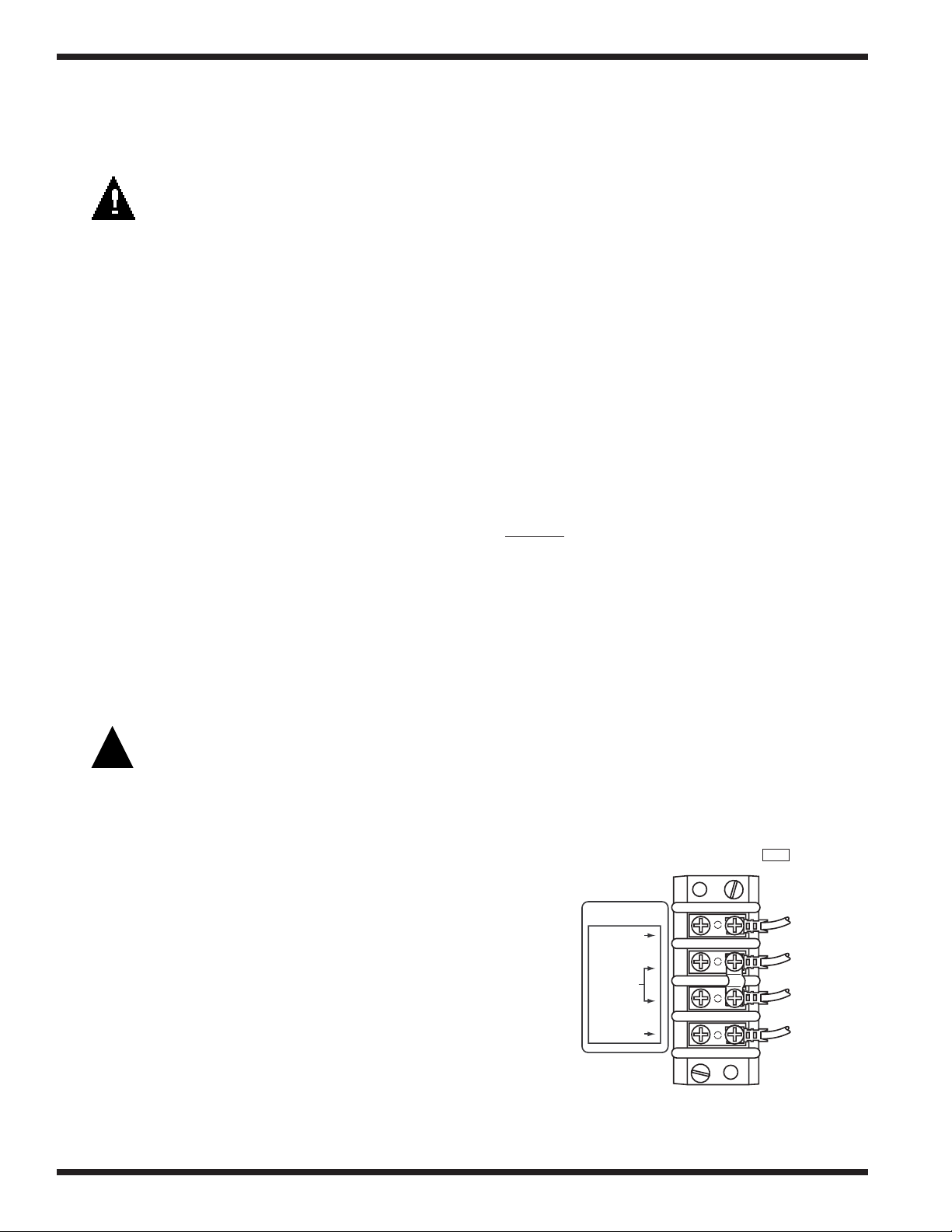
2. Labeled control circuit connection terminals are provided in
the control cabinet for detergent and rinse agent/sanitizer dispensing equipment (supplied by others).
3. Refer to the illustration below. The illustration shows the
terminal board for current production machines beginning
with S/N 88503 and above.
Signal connection points include:
SIGNAL ONLY
120V
RINSE AID/
SANI
COMMON
1R001
• Detergent signal 120VAC, 1 Amp Max amp load.
• Rinse aid/Sanitizer signal 120VAC, 1 Amp Max amp load.
DETERGENT
120V
4. A removable black plug is provided in the load end
side of the wash tank for installation of the
detergent conductivity cell.
6
Chemical Connection
Terminal Board
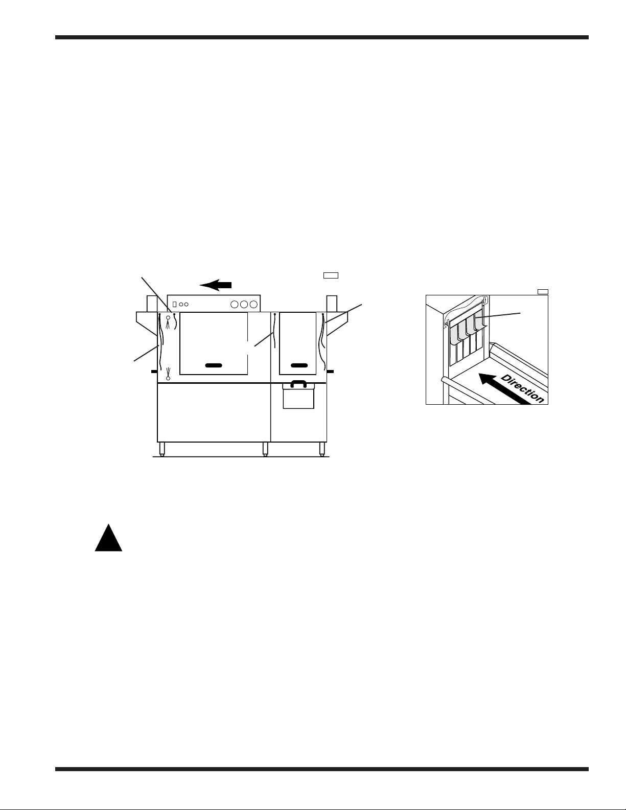
Curtain Locations
!
1R003
WASH
PRE
WASH
R-L Direction
1R002
1. Refer to the illustrations below and hang the curtains as shown.
J-hooks are located in the corners of each section to accept the curtain rods.
• Standard long curtain 24" x 20-1/4" [610mm x 515mm]
• High hood long curtain 24" x 22-3/4" [610mm x 578mm]
• Standard short curtain 24" x 13-1/4" [610mm x 337mm]
• High hood short cutain 24" x 20-1/4" [610mm x 515mm]
• Final rinse curtain 24" x 6-1/4" [610mm x 159mm]
2. Make sure the short flaps of the long curtains face the load end of the dishwasher.
The longest curtains always go on each end of the dishwasher.
Final rinse
curtain
Long curtain
INSTALLATION
Short
flaps
Long curtain
Curtain Locations
(Machine with prewash shown)
Completing Installation
WARNING:
Do not insert racks into machine before tanks fill with water. Operating pumps dry will cause
pump seal damage and leakage that can result in a motor failure.
1. Remove any foreign material from inside the machine.
2. Check to insure that drains and overflow pipes are operational and sealed.
3. Position scrap screens on supports above the tanks.
4. After plumbing and electrical connections are completed, fill the tank and wait 10 minutes.
Check all plumbing connections for leaks.
Load End
Short flaps on long curtains
face the load end of dishwasher
5. Drain the tank and check the drain lines for leaks.
6. The formed down lip of the dishtable should be placed inside the machine. The dishtable
should be pitched toward the dishwasher for proper draining by adjusting its leveling feet.
The dishtable should be sealed to the dishwasher.
7
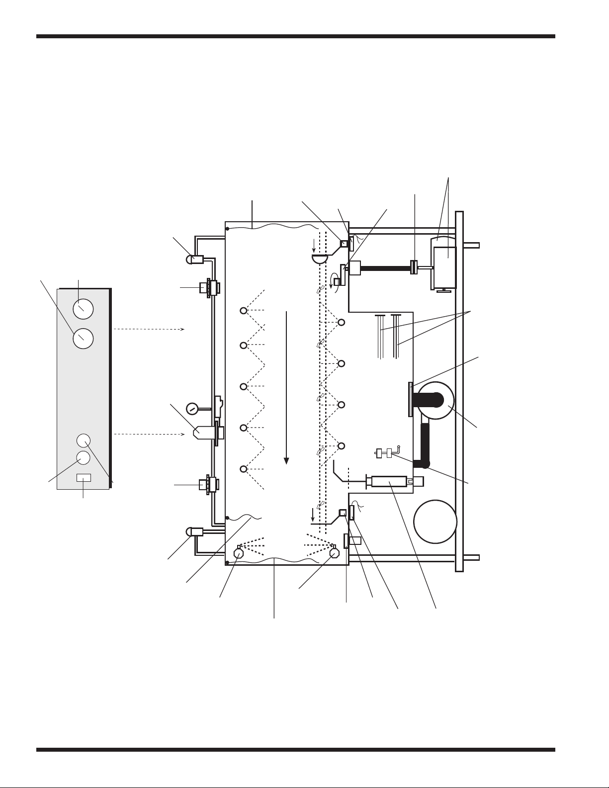
OPERATION
OPERATION PROCEDURE
Final Rinse Water
Wash Water
Temperature Gauge
Temperature Gauge
Vacuum
Breaker
Fill Valve
Long Curtain
Idle Pump
Magnet
Idle Pump
Magnetic Switch
Conveyor Crank
Clutch
Assembly
Conveyor Drive
Motor and Gear
Reducer
Electric Tank
Heaters
Green Start Button
Control Cabinet
Lighted On-Off
Rocker Switch
Pressure
Regulating
Rinse Valve
Red Stop Button
Vacuum
Breaker
Valve
Short Curtain
Right to Left Model
Conveyor Direction
Wash Arm Spray Pipes
Long Curtain
Upper Final Rinse Pipe
Lower Final Rinse Pipe
Wash Arm Spray Pipes
Final Rinse
Drain-off
Rinse-Saver
Adjustment
Magnet
Rinse-Saver
Pump
Wash
Dual Float
Booster
Magnetic Switch
Door Activated
Drain-overflow
Assembly
Strainer
Pump
Switch
Right to Left Model
Simplified Rack Conveyor Dishwasher
8
OPERATION
Rack Conveyor Machine
Operation Procedure
Action Result
Turn Power Switch on
Press green start button
Insert soiled rack
Rack conveys thru machine
Rack activates final rinse
Rack exits the machine
Press stop push button
Drain machine for cleaning
after each meal period
or every 2 hours of use
Lighted On-Off Rocker Switch
on control cabinet will illuminate
Float switch activated
Tank(s) fill with water
When machine is full float
switch cuts off water
and calls for heat.
(Wait for proper temperature)
Conveyor drive motor
is activated
Wash pump starts
Continuous power on wire #13
and #2 120V Detergent signal
20 psi required flow pressure
Power to wire #70 and #2 120V
Rinse/Sanitize signal
Wash pumps shut down (timer)
Conveyor continues to run
Conveyor drive will stop
Check detergent and rinse aid
supply. Replenish if necessary
Doors are closed
Door activated drains
are closed
9

OPERATION
!
!
OPERATION
Follow the procedure below to operate your dishwasher properly.
1. Check that spray pipes, curtains, overflow drains, and scrap screens are in place and clean.
2. Turn on detergent dispenser switches and check detergent supply.
3. Turn on exhaust vent system (if applicable), and make sure it is operating.
4. Close door(s). Push the power switch to the ON position. Tanks will begin filling with water.
5. When tanks are full, check wash tank temperature gauge. Minimum wash temperatures are:
• KL44, KL66 - 140°F/60°C
• 44KB, 54KB, 44WS - 160°F/71°C
• 44KPRB, 54KPRB, 66WS - 160°F/71°C
6. Press the START button on the control cabinet. Only the conveyor will start. The pumps
WILL NOT OPERATE until the first rack enters the machine.
7. Scrap and pre-flush all items to be washed, and load the items into the rack.
DO NOT OVERLOAD RACKS.
Place dishes edgewise in a peg rack, cups and bowls upside down in a flat rack.
Spread silverware evenly in a single layer in a flat rack or
upright (loosely packed) in a cutlery rack.
7. Push the rack into the machine, and the pumps will start automatically.
8. Check the rinse pressure and temperature as the racks pass through the final rinse. This rinse
pressure MUST be 20-22 psi [138-151 kPa] and the final rinse temperature MUST be
180°F/82°C minimum.
9. The pumps will automatically stop shortly after the last rack leaves the machine.
The conveyor will continue to run.
10. The machine may be stopped any time during the cycle by pressing the STOP button on the
control cabinet. When restarted, items inside the machine will be fully washed and rinsed.
11. CLEAN scrap screens, scrap baskets (if applicable) and REPLACE tank water every 2 hours
of operation or after each meal period. Check chemical supply.
CAUTION:
DO NOT allow racks to remain on unload dishtable. This could cause the conveyor to jam
and may damage machine. The installation of a table limit switch is highly recommended and
will reduce the risk of damage.
WARNING:
Do not leave water in tanks overnight.
10

MAINTENANCE
MAINTENANCE
The efficiency and life of your machine is increased by regularly scheduled preventive
maintenance. A well maintained machine gives better results and service. An investment of a few
minutes of daily maintenance will be worthwhile.
The best maintenance you can provide is to keep your machine clean. Components that are not
regularly cleaned and flushed will clog and become inoperative.
Intervals shown in the following schedules represent an average length of time between necessary maintenance. Maintenance intervals should be shortened whenever your machine is faced
with abnormal working conditions, hard water, or multiple shift operations.
Maintenance Schedule
CLEANING
• Daily-Every 2 Hours of Operation
1. Turn power switch to OFF.
2. Remove all scrap screens, scrap baskets (if applicable), and pull drain lever(s) to drain
water. Clean inside of tanks and flush with clean water. Backflush scrap screens until clean.
Do not strike screens against solid objects.
3. Remove the spray pipes by a 1/4 turn, counterclockwise. Remove the end plug from each
spray pipe. Flush pipe and nozzles until clean. Do not strike spray pipes against solid
objects. Replace end plugs, verify that rubber seals are in place on manifolds. Reinstall
spray pipes using a 1/4 clockwise turn.
4. Remove and clean curtains. Hang them off the dishtable to dry.
5. Leave the doors open between operations to allow drying.
6. Verify that final rinse nozzles are clean and free of internal hard water deposits. Clean rinse
nozzle orifices with a small paper clip. Consult your chemical supplier for the proper use
and kind of deliming chemical.
7. Report any unusual conditions to your supervisor.
• As Required
1. Check temperature and pressure gauge readings.
2. Inspect machine and check pump motor for leaks around the shaft.
3. Check chemical supplies and refill as necessary.
• Weekly
1. Inspect all water lines for leaks and tighten at joints if required.
2. Clean all detergent residue from exterior of machine.
3. Check drain/overflow tube for leaks.
4. Clean accumulated scale from heating element.
5. Remove and closely inspect each spray arm for blockage.
11

MAINTENANCE
!
• Weekly (Cont.)
6. Straighten a paper clip and use it to clear each rinse nozzle.
7. Inspect pawl bars and drive assembly for wear and freedom of travel.
8. Check float switches in tank for freedom of travel.
9. Check idle pump and final rinse levers for freedom of travel.
DELIMING
Your dishwasher should be delimed regularly as required. This will depend on the mineral content of your water.
Inspect your machine interior for lime deposits. If deliming is required, a deliming agent should
be used for best results. Consult your chemical supplier for proper type and procedures.
If you have the chemical sanitizing model (KL44 and KL66), carefully follow the following procedure before deliming:
DANGER:
Deliming solution, rinse agents, or other acids must not come in contact with household bleach (sodium hypochlorite) or any chemicals containing chlorine, iodine,
bromine, or flourine. Mixing may cause hazardous gases to form. Consult your
chemical supplier.
1. Remove the suction tube assembly from the bleach container and place it as close as possible
to the floor. Place a catch pan under it.
2. Cycle the machine approximately six times to purge the lines of the bleach.
3. Proceed with deliming process.
12

TROUBLESHOOTING
TROUBLESHOOTING
In order to find the cause of a breakdown or abnormal operating condition in your dishwasher
please ensure that:
1. All switches are ON
2. Drain and overflow tube are in place and seated
3. Wash pipe and rinse nozzles are clean
4. Scrap screen(s) and scrap basket (if applicable) are properly positioned
5. Spray pipes are in their proper positions
6. Thermostat(s) are at their correct setting
7. Sanitizer, detergent, and rinse additive dispensers are adequately filled
8. Doors are fully closed.
If a problem still exists, use the following table for troubleshooting
CONDITION CAUSE SOLUTION
Machine will not start Door not closed.................................. Make sure doors are fully closed
Door safety switch faulty .................. Contact your service agency
Start switch faulty .............................. Contact your service agency
Main switch off.................................. Check disconnect
No rack inserted ................................ Place rack in unit
Overload protector tripped ................ Reset overload in control box
Low or no water Main water supply is turned off ........ Turn on house water supply
Drain/overflow tube is not
in place and seated ............................ Place and seat drain tube
Machine doors not fully closed ........ Close doors securely
Faulty fill valve.................................. Contact your service agency
Stuck or defective float...................... Check floats and clean
Clogged ‘Y’ strainer .......................... Clean or replace
Continuous water filling Stuck or defective float...................... Check floats and clean
Fill valve will not close...................... Clean or replace
Drain tube not in place ...................... Look for drain tube in tank
Any motor not running Overload protector tripped ................ Reset overload in control box
Defective motor ................................ Contact your service agency
Wash tank water temperature Incoming water temperature
is low when in use at machine too low ............................ Raise temperature to:
140°F/60°C for 44KB, 54KB, 44WS,
44KPRB, 54KPRB, 66WS
120°F/49°C for KL44, KL66
Defective thermometer ...................... Check or replace
Defective thermostat .......................... Check for proper setting or replace
Defective heater element .................. Check or replace
Low steam pressure .......................... Check steam supply pressure
Defective steam trap .......................... Check or replace
Defective solenoid valve.................... Check or replace
13

TROUBLESHOOTING
CONDITION CAUSE SOLUTION
Insufficient pumped spray Clogged pump intake screen.............. Clean
pressure Clogged spray pipe ............................ Clean
Insufficient final rinse or no Faulty pressure reducing valve .......... Clean or replace
final rinse Improper setting on pressure
Low final rinse temperature Low incoming water ........................ Check the booster (KB, KPRB,WS models)
Poor washing results Detergent dispenser not
Scrap screen full ................................ Must be kept clean and in place
Low water level in tank...................... Check drain and overflow tube
Pump motor rotation incorrect .......... Reverse connection between L1
and L2 in control cabinet (3 phase only)
Defective pump seal .......................... Contact service agent
reducing valve.................................... Set flow pressure to 20-22 psi [138-151 kPa]
Clogged rinse nozzle and/or
pipe .................................................... Clean with paper clip/delime
Improper water line size .................... Have installer change to proper size
Clogged ‘Y’ strainer .......................... Clean or replace
be sure the thermostat is set to maintain
180°F/82°C temperature. (KL models) check
incoming water is set min. 120°F/49°C140°F/60°C.
Check valve to be sure it is clean
and operating.
Defective thermometer ...................... Check for proper setting or replace
operating properly.............................. Contact detergent supplier
Insufficient detergents ...................... Contact detergent supplier
Food Soil concentration too
high in wash tank .............................. Drain tank, clean and refill every 2 hours of
operation or after each meal period.
Wash water temperature
too low .............................................. See condition “Wash Tank
Water Temperature” above
Wash arm clogged.............................. Clean
Improperly scraped dishes ................ Check scraping procedures
Ware improperly
placed in rack .................................... Use proper racks. Do not overload racks
Improperly cleaned
equipment .......................................... Unclog wash sprays and rinse nozzles
to maintain proper pressure and flow
conditions. Overflows must be open.
Keep wash water as clean as possible.
Electric elements or steam
coils has soil/lime buildup ................ Clean and delime
14
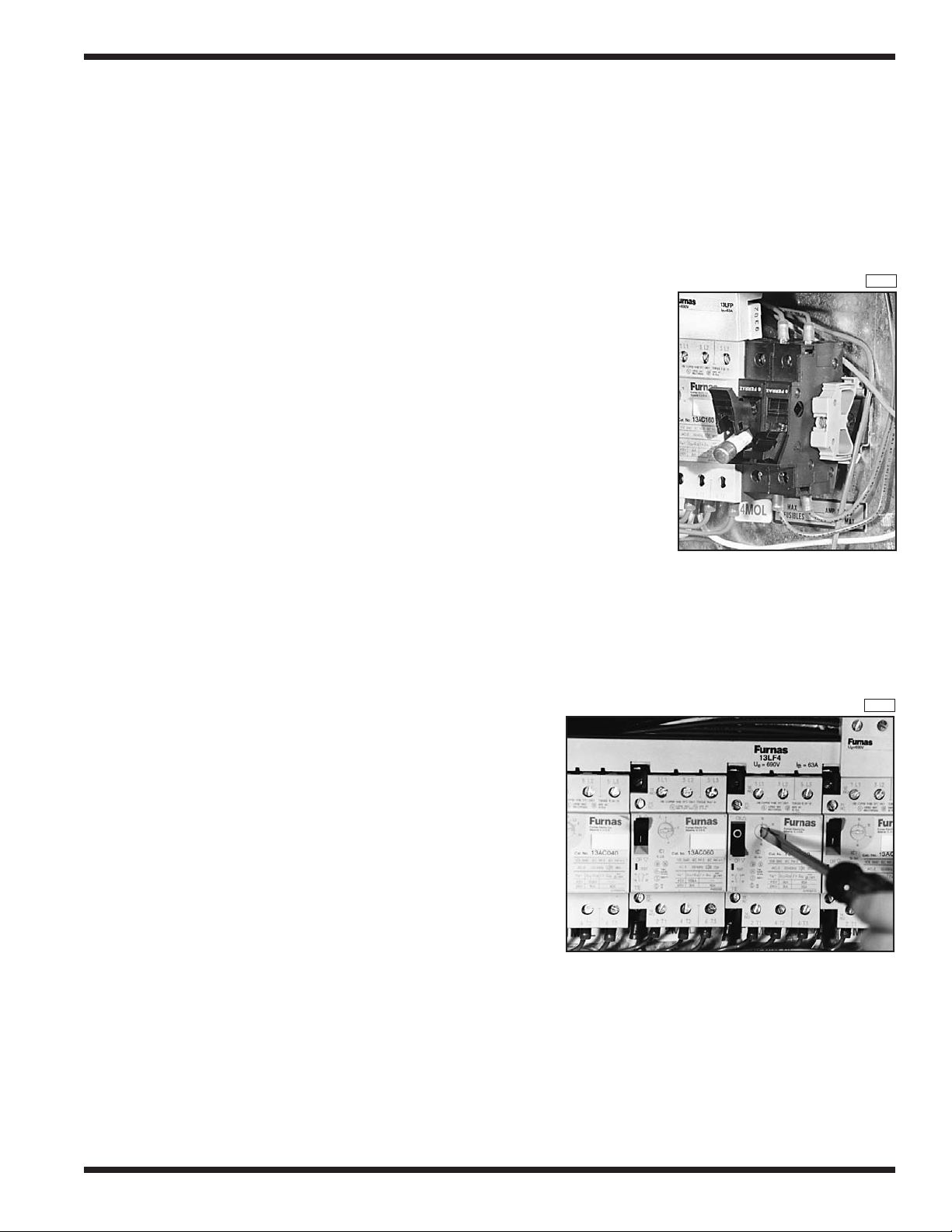
ELECTRICAL SERVICE
Fuse Blocks—120VAC Control Voltage
Two fuse blocks, located in the center rear of the main control cabinet
protect the main control transformer. Each fuse block holds a fuse.
The fuses are marked 1FU and 2FU on the electrical schematic.
To Replace the fuse:
• Disconnect power to the machine at the main service switch.
• Flip the tab on the top of the fuse block to open the block.
• Remove the fuse and replace it.
• Close the fuse block and turn the main power on.
• If the fuse blows again, DO NOT INCREASE THE FUSE SIZE.
• DETERMINE THE CAUSE OF THE OVERLOAD.
Fig. 1 shows the fuse block opened and the fuse exposed.
Motor Overloads
Motor overloads are located to the left of the fuse blocks inside
the control cabinet. Each motor has one overload to protect it from line
voltage electrical overloads. In addition, an auxilary set of switch
contacts is built into the overload. The switch contacts
disconnect 120VAC power to the motor contactor coils in the
event of an overload condition. Refer to Fig. 2.
Note the Switch Lever on the Overload.
• If the switch lever is off with the “0” showing
then the overload has tripped on an overload.
ELECTRICAL SERVICE
1R004
Figure 1
Fuse Blocks
To Reset the Motor Overload:
• Flip the starter switch to the On position.
• Run the dishwasher and test the AMP
draw of the motor in question. If the motor
checks okay then there may be a wiring
problem or the overload may be defective.
To Replace a Motor Overload:
• Disconnect the wires to the overload.
• Release the mounting catch on the front
side of the overload, push forward and lift out.
• Snap the new overload into place and
reconnect the wires.
To adjust the overload setting:
The screwdriver in Fig. 2 is positioned
to adjust the motor overload AMP setting.
• Read the FLA motor amps that applies for the
machine voltage on the Motor Nameplate.
• Turn the setting to match nameplate FLA.
1R005
Figure 2
Motor Overload
15
ELECTRICAL SERVICE
0
1
2
3
UP
4
5
6
Omron
H2C
6M
1R006
50
60
1
2
3
4
5
6
7
8
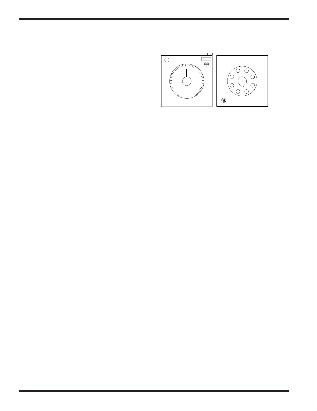
1R007
Pump Timer
Refer to F
ig. 3
The automatic timer located in the left center of the
control cabinet is set at the factory.
The Pump Timer controls the amount of time that
the pumps will run before the last rack enters the
load end of the dishwasher tunnel.
The Pump Timer is an OFF DELAY timer.
Each timer is marked
with a tag noting
the time set by the factory.
The timer has the following user defined settings:
1. Adjustable timer range
2. Timer knob setting
3. Indicator light (ON when timer is counting)
4. 50 Hz or 60 Hz setting on the back of the timer
To Replace a Timer:
• Disconnect power to the machine at the main service switch.
• Remove the defective timer and install the replacement.
• Adjust the new timer setting to match the setting
of the original timer.
BackFront
Figure 3
Pump Timer
Operation Sequence:
• A dishrack entering the machine contacts the idle pump switch lever.
• Normally closed contacts of the idle pump switch open, de-energizing control relay 1CR.
• Normally closed contacts (1, 9) of 1CR close and apply 120VAC to reset coil of pump timer.
• Pump timer resets.
• The dishrack moves off the idle pump switch lever. The switch contacts close.
• 1CR energizes and contacts (1, 9) open removing 120VAC from the pump timer reset coil.
• The pump timer begins to time down for its preset time setting.
• The timer is reset each time the idle pump switch is activated. If the timer is reset only once it
will time out and shut the pumps off after the rack has exited the dishwasher.
To Check the Pump Timer Setting:
• Turn the power on.
• Place a rack on the conveyor.
• Press the Green start button. The conveyor drive will start.
• When the rack enters the load end the pumps will start.
• Wait for the rack to exit the tunnel at the unload end.
• When the pumps stop, push the red stop button.
• Measure the distance between the exit end of the tunnel and the rack.
• The rack should be about 1 foot past the end of the tunnel.
• If the distance is less than 1 foot, increase the pump timer setting. Continue to increase the
timer setting a few seconds at a time until the proper distance is reached.
• If the measured distance is greater than 1 foot, decrease the pump timer setting. Continue to
decrease the timer setting a few seconds at a time until the proper distance is reached.
16
ELECTRICAL SERVICE
ELECTRICAL SERVICE (Cont.)
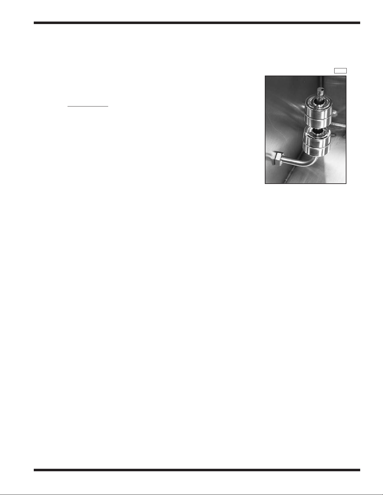
Automatic Fill/Low Water Heat Protection
Dual Float Switches –
Refer to F
Each tank contains a dual float. The device consists of
an angled stem containing two reed switches.
Two stainless steel ball floats slide over the
stem and are free to move up and down.
The floats contain magnets. When the float moves on the
stem, it opens and closes its associated reed switch inside the
stem. The reed switches control relays. The relays control the
automatic fill and heat for different parts of the machine.
Float switches and their relays operate on 24VAC.
Circuit Explanation –
The following is a general explanation of the float switch circuit.
Refer to the electrical schematic on your machine for a detailed description
of the individual floats, relays, and wiring.
Bottom Float and Reed Switch:
• The bottom float controls the heat.
• When the bottom float is down, the bottom reed switch contacts are open.
• When the bottom float is up, the bottom reed switch contacts close.
ig. 4
1R008
Figure 4
Dual Float
Switch
Top Float and Reed Switch:
• The top float controls a fill valve.
• When the top float is down, the top reed switch contacts are open.
• When the top float is up, the top reed switch contacts are closed.
Initial Fill –
• When the tank is completely empty, both floats are down and their reed switch contacts
are open.
• The control relay for the float switch is de-energized.
• The fill valve for the tank is energized and the tank begins to fill with water.
• As the water level in the tank rises, the bottom float begins to move up.
• When the bottom float is completely up, its NO reed switch contacts close.
• This prepares the heat circuit, but the heat Does Not energize at this time.
• The tank continues to fill until the top float is completely up.
• The top float’s NO reed switch contacts close. Its control relay energizes.
• The fill valve de-energizes.
• The heat circuit energizes through the float switch and the contacts of the control relay.
During Normal Operation –
• If the water level in a tank falls below the level of the top float, the top float moves down and
its reed switch contacts open.
• When the water level falls below the level of the bottom float, the bottom float moves down
and its reed switch opens.
• The control relay de-energizes. The fill valve energizes and refills the tank.
• The heat circuit will de-energize until the water level in the tank raises the top float again.
• The bottom float keeps the heat circuit ready as long as the water level is above the level of the
bottom float.
17
ELECTRICAL SERVICE
ELECTRICAL SERVICE (Cont.)
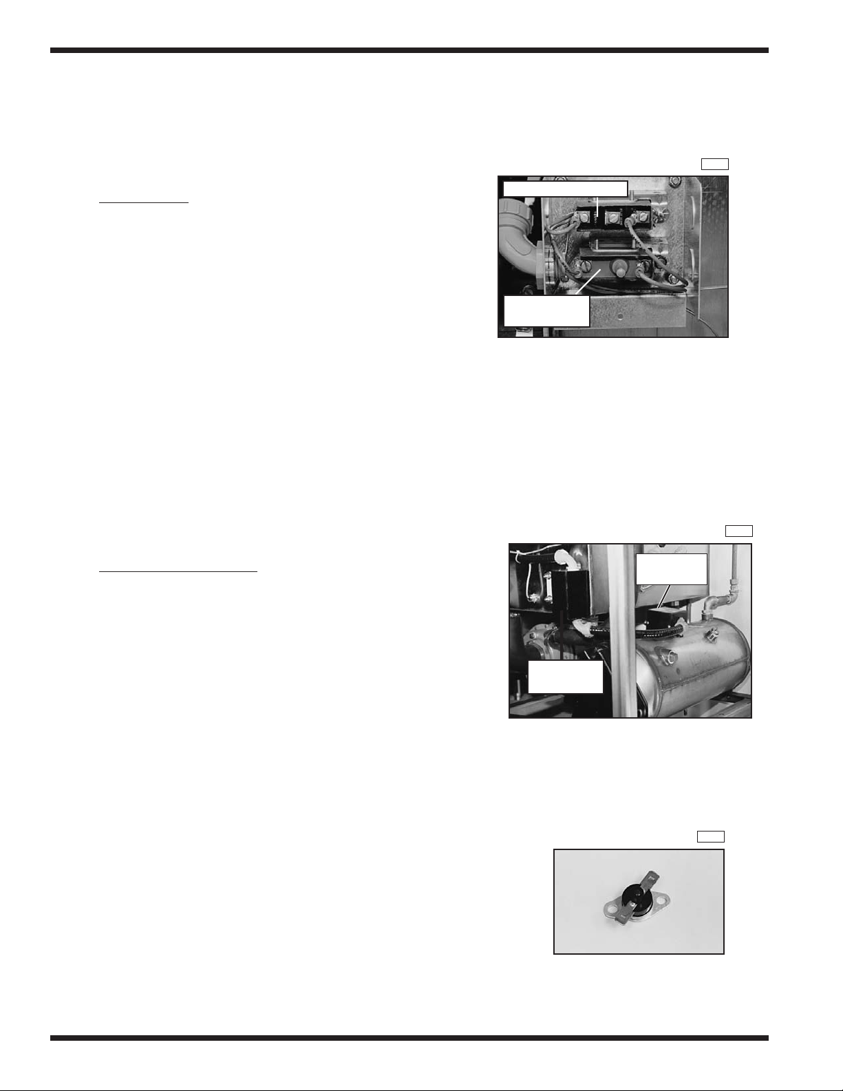
Thermostat Locations and Adjustments
Refer to F
Electric tank heat is controlled by two thermostats.
1. The control thermostat which regulates the temperature.
2. The high limit thermostat which protects from overheating.
Location:
Both thermostats are located on front of tank, inside a black
enclosure box behind the front access panel.
Adjustment:
The Control Thermostat has an adjustment screw on one side.
• The thermostat is wired Normally Closed.
• Turn the adjustment screw clockwise to increase
the temperature in the tank and counterclockwise
to decrease the temperature in the tank.
The High Limit Thermostat is not adjustable.
It contains a red reset button in its center.
• The red button pops out if the temperature
in the tank exceeds 210°F/99°C.
• Press the red button in to reset the high limit.
Determine the cause of the high temperature condition.
Refer to Fig. 6 and Fig. 7.
Electric Booster Heat is controlled by two thermostats.
ig. 5
1R009
Control Thermostat
High limit
Thermostat
Figure 5
Tank Heat Thermostats
1R010
High Limit
Thermostat
1. The control thermostat which regulates the temperature.
2. The high limit thermostat which protects from overheating.
3. Each tank has a control and a high limit thermostat.
Location:
Control
Thermostat
The control thermostat is enclosed in a black box mounted
on the front of the wash tank behind the front access panel.
The high limit thermostat is enclosed in a box mounted
on top of the booster tank.
Booster Thermostat Locations
Adjustment:
The control thermostat has an adjustment screw on one side.
• The thermostat is wired Normally Closed.
• Turn the adjustment screw clockwise to increase the booster tank temperature
and counterclockwise to decrease the booster tank temperature.
The high limit thermostat is a bimetal snap design. It is not adjustable.
• A button with a red dot in the center pops out when
the temperature exceeds 210°F/99°C.
• Press the red reset button in to reset the high limit.
Determine the cause of the high temperature condition.
Booster – High Limit Thermostat
Figure 6
1R011
Figure 7
18
ELECTRICAL SERVICE
1L1
1L2
1L3
1L1
1L2
1L3
1L1
1L2
1L3
1L1
1L2
1L3
1L2
1L1
1L1
1L2
1L1
1L2
1L1
1L2
1L3
1L1
1L2
1L3
1L1
1L2
1L3
1L1
1L2
1L3
1L1
1L2
1L3
1L1
1L2
1L3
1L1
1L2
1L3
1L1
1L2
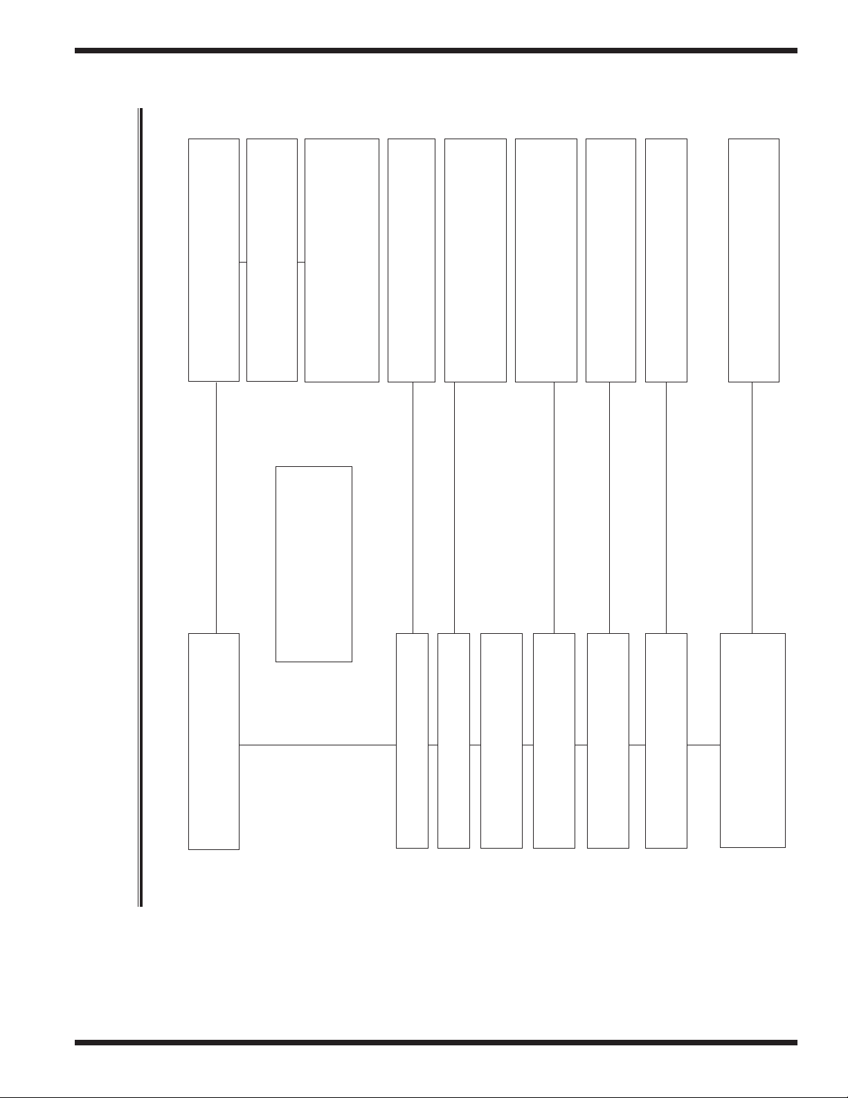
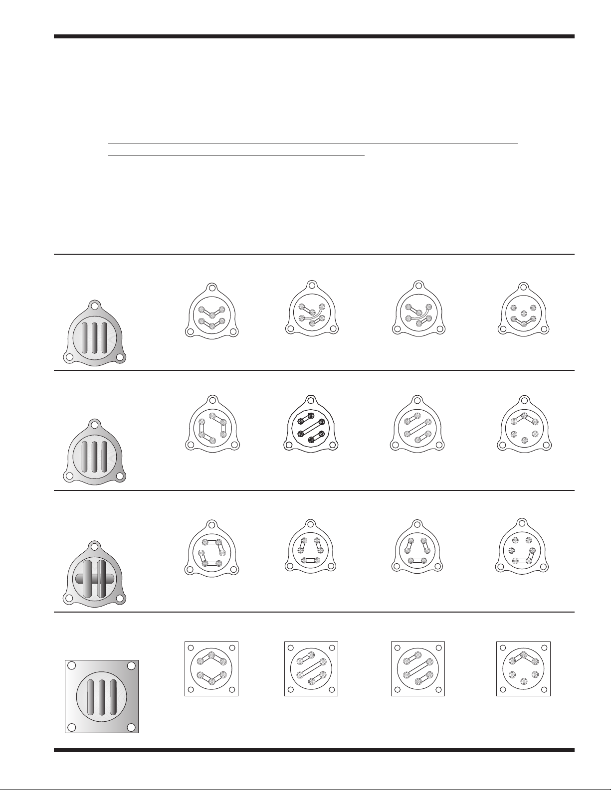
ELECTRICAL SERVICE (Cont.)
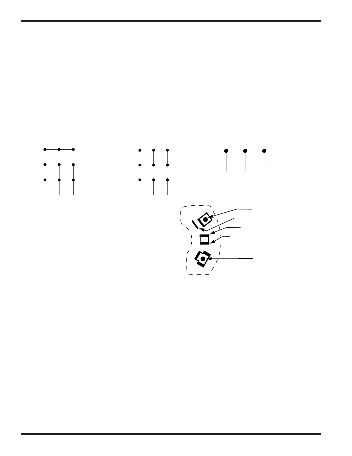
Heater Element Wiring – Booster Tank and Wash Tank Heater Elements
Refer to the illustrations and follo
to make line power connections to a replacement element.
Step 1. Hold the element assembly with the calrod coils facing toward you.
Step 2. Match your element coil to Configuration A, B, C, or D.
Step 3. Rotate your element coils to match the correct configuration.
Step 4. Flip the element over and match your element to the correct terminal configuration.
Step 5. Install terminal jumpers according to the illustration for your voltage requirement.
Step 6. Install the element and make your line connections 1L1, 1L2, or 1L3 per the illustration.
Configuration A
Booster tank element
View of calrod coils
Configuration B
Booster tank element
View of calrod coils
208V/1 Phase
w the steps below to properly install terminal jumpers and
Terminal Connections view of element
208-240V/3 Phase
Delta Connection
480V/3 Phase
575V/3 Phase
Delta Connection
208-240V/3 Phase
Wye Connection for
380-415V/3 Phase
Terminal Connections view of element
1L1
1L2
1L3
Configuration C
208V/1 Phase
208-240V/3 Phase
Delta Connection
480V/3 Phase
575V/3 Phase
Delta Connection
Terminal Connections view of element
208-240V/3 Phase
Wye Connection for
380-415V/3 Phase
Booster tank element
View of calrod coils
Configuration D
208V/1 Phase
208-240V/3 Phase
Delta Connection
480V/3 Phase
575V/3 Phase
Delta Connection
Terminal Connections view of element
208-240V/3 Phase
Wye Connection for
380-415V/3 Phase
Wash tank element
View of calrod coils
208V/1 Phase
208-240V/3 Phase
Delta Connection
480V/3 Phase
575V/3 Phase
Delta Connection
208-240V/3 Phase
Wye Connection for
380-415V/3 Phase
19
ELECTRICAL SERVICE
321
LINE
654
987
321
LINE
2
8
J
LINE
LINE
L1
L2
4
3
654
987
321
LINE
Motors
Motor Specifications
Voltage: Standard motors are multi-voltage
Low voltage: 208-230VAC
High voltage: 460VAC or 575VAC only
Phase: Motors may be single or three phase
Wiring Connections:
Refer to the diagrams below for 3 phase motor lead wiring.
Low voltage High Voltage 575V/3PH
208-230V/3PH 460V/3PH Only
Troubleshooting:
Motor will not run:
1. Check incoming power to control cabinet.
2. Check for tripped manual motor starter (overload) in control cabinet.
(Refer to Motor Overload service section for the proper setting)
3. Check power at motor contactor.
Motor runs hot and trips motor starter overload:
1. Check for proper voltage between L1-L2, or (L1-L2, L2-L3, L1-L3 for 3 phase).
2. Check FLA on motor leads L1, L2, (also L3 for 3 phase) using amp tester.
(Motor full load amp (FLA) ratings are stamped on motor nameplate).
Motor Replacement:
1. Disconnect the power to the machine.
2. Disconnect the wires at the motor junction box.
3. Make note of the motor connections in order to phase the replacement correctly.
4. Install the new motor and check for proper rotation.
5. Proper shaft rotation is clockwise looking at the rear of the motor.
6. Motor rotation can be reversed by switching L1 and L2 on 3 phase motors. Single phase
20
motor rotation cannot be reversed
7. Replacement motors are available as complete assemblies.
8. Champion cannot provide replacement bearings, stators, or rotors for motor repair parts.
Refer to the diagram at right
for single phase motor lead wiring.
Low voltage
208-230V/1PH
Only
ELECTRICAL SERVICE
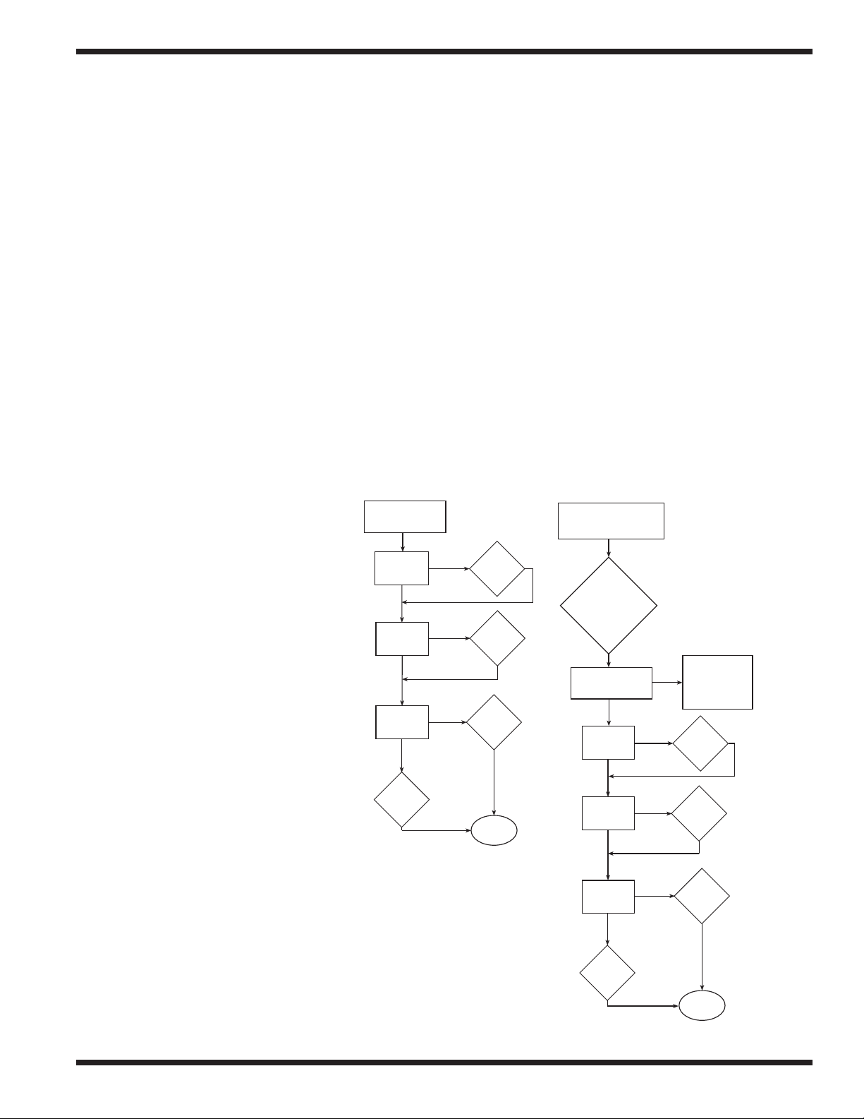
YES
Water Shuts OFF
Machine is in
Final Rinse Mode
Not a Dual Float
Problem
System
Checks
System
Checks
YES
YES
YES
YES
YES
YES
NO
NO
NO
NO
NO
NO
NO
Wash or Prewash
Tank Fills Constantly
Is Tank Full
of Water?
Are the Float
Balls Up?
Close
Drain
Valve
Clean
Float
Assy
Is Heat ON
when called
for?
Replace
Dual
Float
Check
Solenoid
Valve
Are the Float
Balls Up?
Check
Solenoid
Valve
Is Heat ON
when called
for?
Replace
Dual
Float
Clean
Float
Assy
Close
Drain
Valve
Is Tank Full
of Water?
Check to ensure
that
Rinse-Saver Lever
is not
Operated
Water Runs Constantly
Through Final Rinse Piping
Dual Float Switches –
Troubleshooting:
The dual float controls fill and heat circuits.
Identifying a Dual Float Problem:
The most common trouble conditions associated with a dual float failure are:
1. The tank fills constantly.
2. The tank heat will not come on.
Inspect the Dual Float:
1. Be sure that the dual float assembly is clean and free of scale build-up.
2. Be sure that the stainless steel balls on the float assembly move up and down freely.
In addition to checking the float operation, perform the following—
System Checks:
1. All drain valves are fully closed.
2. Incoming water supply Flow Pressure is 20-22 psi [138-151 kPa].
3. Fuses in control cabinet are good (Electric Heat Only).
4. Tank Heat thermostats and/or High limit thermostats operate correctly.
5. Booster Heat thermostats and/or High limit thermostats operate correctly.
Dual Float Troubleshooting Diagrams:
21
ELECTRICAL SERVICE
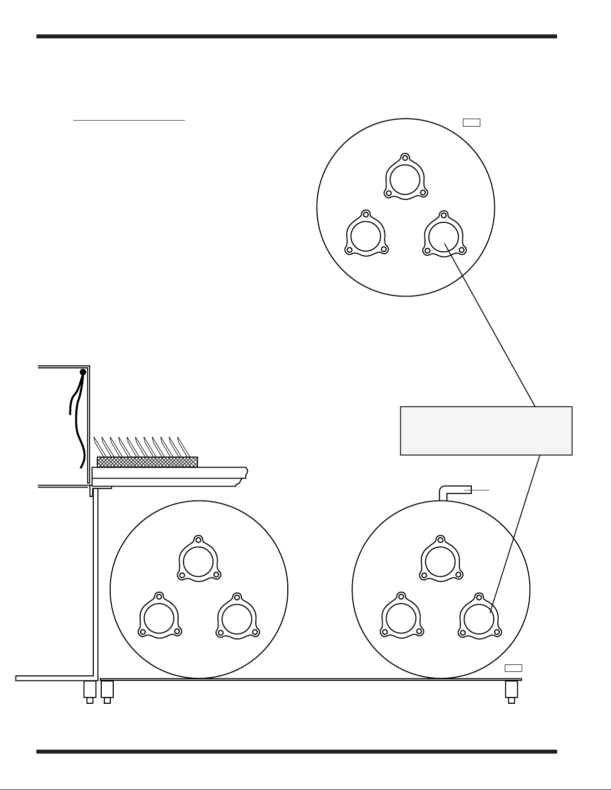
1R013
Electric Booster Heater — Element Installation
Refer to F
ig. 8 and Fig. 9
Champion built-in boosters are constructed of
stainless steel and have locations for three electric
booster heater elements.
1. The two booster configurations for rack
conveyor models are:
Single tank - 40°F/22°C rise booster
Two tank - 70°F/39°C rise booster (except WS)
The total Kw rating of the booster assembly is
determined by the model number of the machine
and the minimum temperature of the incoming
water supply.
2. The highest rated Kw element
should always be installed in the
bottom right corner location of
booster canister No. 1.
1R012
10Kw
10Kw
Canister No.1
Figure 8
Front View
Typical 40°F/22°C Rise Booster
One Tank – Total 38Kw Shown
For machines built prior to S/N 87575
18Kw
Dishwasher
Unload
End
L-R Direction
9Kw
Canister No.2
9Kw9Kw
Figure 9
Front View
Typical 70°F/39°C Rise Booster
Two-Tank – Total 63Kw Shown
For machines built prior to S/N 87575
Highest Rated Kw Element
installed in bottom right corner
of Canister No.1
Water
Supply
In
9Kw
9Kw
Canister No.1
18Kw
22
MECHANICAL SERVICE
MECHANICAL SERVICE
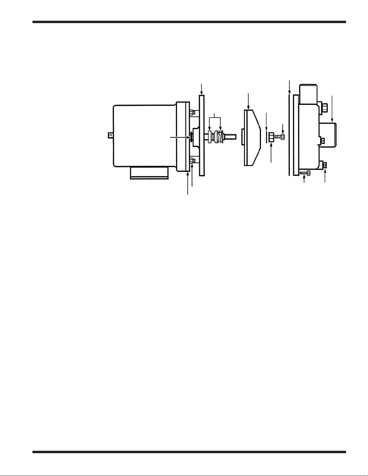
Pump Seal Replacement:
Pump Flange
Impeller
Gasket
WARNING:
Disconnect all
power to the
machine at the
main power
Seal Assy
Washer
Bolt
(B)
source and
place a tag at
the disconnect
Water
Slinger
switch to show
that work is
being done
on the circuit.
Backing Plate
Backing Plate
Mounting Nut
Nut
Bolt
(A)
1. Disconnect the power to the machine.
2. Drain the machine. Remove the plug from the lowest point on the pump volute and drain
the pump.
3. Remove the pump hoses.
4. Disconnect the wires to the motor at the motor junction box.
5. Unbolt the motor from the base of the machine and remove the motor and pump.
6. Remove all the bolts (A) on the volute and carefully remove the volute from the pump flange.
7. Lock the motor shaft holding the square end of the rear shaft with a wrench or vise grips.
8. Remove the impeller retaining bolt (B). Remove the large retaining nut and washer.
9. Remove the impeller using a strap wrench. Turn it counterclockwise. Do not strike the
impeller with a hammer to loosen or remove it.
10. Check the impeller counterbore for shim washers. Be sure to reinstall. Not all impellers
have shims.
11. Remove the old seal and discard. Check the seal seat in the pump flange and clean thoroughly.
12. Clean the seating surface on the motor shaft with #600 emery paper or crocus cloth.
13. Check the water slinger and replace if worn or missing. Remove the (4) backing plate mtg.
nuts to gain access to the slinger.
14. Press the rubber seal and ceramic into the pump flange. Use a water soluble lubricant. Keep
the ceramic clean.
15. Install the rotating part of the seal on the shaft with the graphite surface toward the ceramic.
Use a water soluble lubricant.
16. Reinstall the impeller, washer, lock-nut, and bolt. Install a new flange gasket. Bolt the volute
to the flange.
17. Reinstall the pump and motor assembly on the base of the machine and reconnect the
pump hoses.
18. Reconnect the power and fill the tank with water. Check for leaks.
19. Bump start the pump to check the motor for correct rotation.
20. Proper shaft rotation is clockwise looking at the rear of the motor.
Volute
Plug
23
 Loading...