

Page 1
CONTROLLER
BOARD
GL
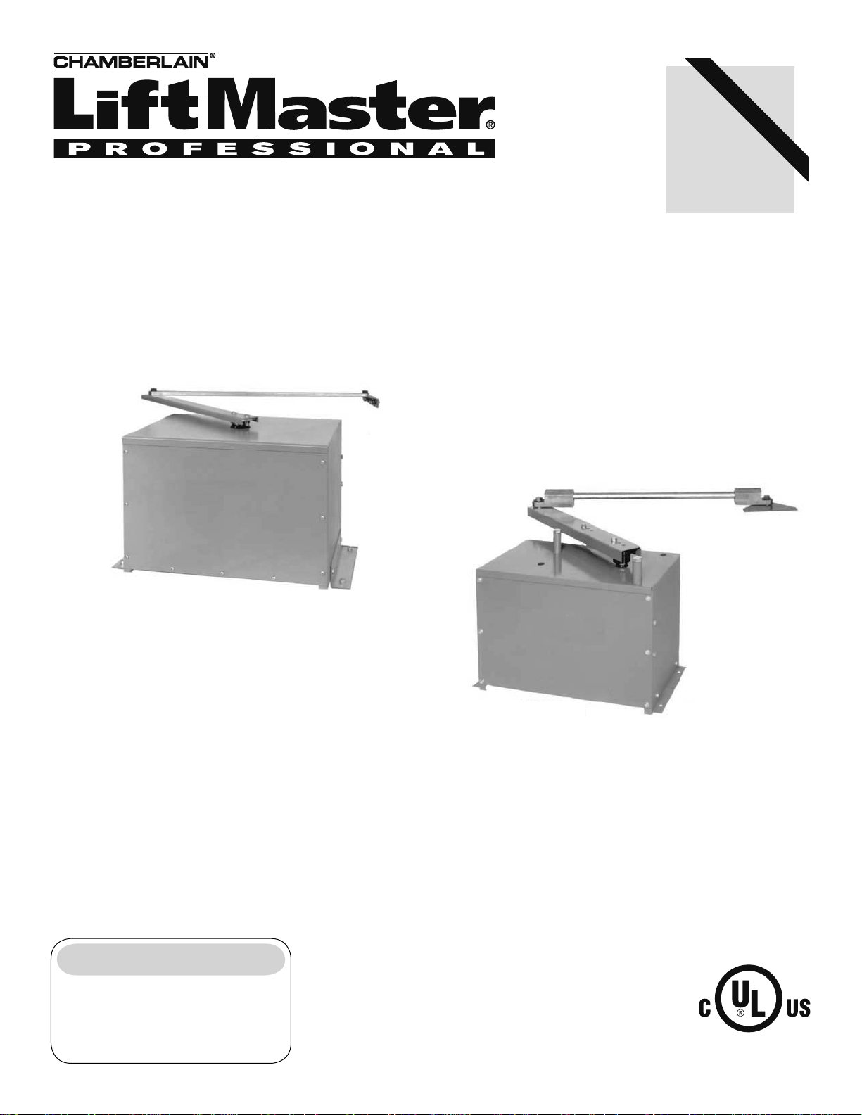
MODEL SW470
MEDIUM DUTY SWING GATE OPERATOR
Serial # _______________________
(located on electrical box cover)
Installation Date _________________
2 YEAR WARRANTY
MODEL SW490
HEAVY DUTY SWING GATE OPERATOR
INTENDED FOR PROFESSIONAL INSTALLATION ONLY.
VISIT WWW.LIFTMASTER.COM TO LOCATE A PROFESSIONAL
INSTALLING DEALER IN YOUR AREA.
THIS MANUAL IS TO BE LEFT WITH THE PROPERTY OWNER.
MODELS SW470 AND SW490 ARE FOR VEHICULAR PASSAGE GATES
ONLY AND NOT INTENDED FOR PEDESTRIAN PASSAGE GATE USE.
Page 2
TABLE OF CONTENTS
WARNING WARNING
WARNING
WARNING WARNING
WARNING
CAUTION CAUTION
WARNING
WARNING
OPERATOR SPECIFICATIONS
Carton Inventory . . . . . . . . . . . . . . . . . . . . . . . . . . . . . . . . . . . . . . 2
Operator Dimensions and Specifications . . . . . . . . . . . . . . . . . . .3
UL325 Model Classifications . . . . . . . . . . . . . . . . . . . . . . . . . . . . 4
OPERATOR WARNINGS
Suggested Safety Protection Device Locations. . . . . . . . . . . . . . .5
Safety Installation Information . . . . . . . . . . . . . . . . . . . . . . . . . . . 6
Gate Construction Information . . . . . . . . . . . . . . . . . . . . . . . . . . . 7
Safety for Swing and Ornamental Grill Type Gates . . . . . . . . . . . . 8
Warranty Sign Placement . . . . . . . . . . . . . . . . . . . . . . . . . . . . . . .8
INSTALLATION
Post Mounting (SW470) . . . . . . . . . . . . . . . . . . . . . . . . . . . . . . . .9
Pad Mounting (SW470) . . . . . . . . . . . . . . . . . . . . . . . . . . . . . . .10
Pad Mounting (SW490) . . . . . . . . . . . . . . . . . . . . . . . . . . . . . . .11
Control Arm and Gate Bracket Installation (SW470). . . . . . . . . .12
Control Arm Assembly (SW490) . . . . . . . . . . . . . . . . . . . . . 13-14
Manual Disconnect . . . . . . . . . . . . . . . . . . . . . . . . . . . . . . . . . . .14
WIRING
Power Wiring Installation . . . . . . . . . . . . . . . . . . . . . . . . . . . . . .15
On/Off Switch Power Wiring. . . . . . . . . . . . . . . . . . . . . . . . . . . . 16
Stop/Reset Button Control Wiring . . . . . . . . . . . . . . . . . . . . . . . 16
ADJUSTMENT
Programming the Radio Receiver. . . . . . . . . . . . . . . . . . . . . . . . 17
Limit Switch Adjustment. . . . . . . . . . . . . . . . . . . . . . . . . . . . . . .18
RPM Sensor (Hall Effect) Adjustment. . . . . . . . . . . . . . . . . . . . .19
SAMS (Sequenced Access Management System) . . . . . . . . . . . 20
Accessory Wiring . . . . . . . . . . . . . . . . . . . . . . . . . . . . . . . . . 21-22
Control Board Illustration . . . . . . . . . . . . . . . . . . . . . . . . . . . . . . 23
Controller Programming and Features . . . . . . . . . . . . . . . . . 24-25
Program Settings . . . . . . . . . . . . . . . . . . . . . . . . . . . . . . . . . 26-27
TROUBLESHOOTING
MAINTENANCE
Operator Maintenance. . . . . . . . . . . . . . . . . . . . . . . . . . . . . . . . . 30
Single Phase Wiring Diagram (SW470) . . . . . . . . . . . . . . . . . . . 31
Single Phase Wiring Diagram (SW490) . . . . . . . . . . . . . . . . . . . 32
Three Phase Wiring Diagram (SW490). . . . . . . . . . . . . . . . . . . .33
Control Connection Diagrams . . . . . . . . . . . . . . . . . . . . . . . . . . .34
Repair Parts and Illustrated Parts - SW470 . . . . . . . . . . . . . 35-36
Repair Parts and Illustrated Parts - SW490 . . . . . . . . . . . . . 37-38
Variable Parts - SW490 . . . . . . . . . . . . . . . . . . . . . . . . . . . . . . . 39
Safety Accessories for Secondary Entrapment Protection . . . . .39
WARRANTY POLICY AND SERVICE
IMPORTANT NOTE
• BEFORE attempting to install, operate or maintain the operator,
you MUST read and fully understand this manual and follow all
safety instructions.
• These instructions are intended to highlight certain safety related
issues. These instructions are not intended to be comprehensive.
Because each application is unique, it is the responsibility of the
purchaser, designer, installer and end user to ensure that the
total gate system is safe for its intended use.
. . . . . . . . . . . . . . . . . . . . . . . . . . .
. . . . . . . . . . . . . . . . .40
28-29
Mechanical
Electrical
When you see these Safety Symbols and Signal Words on the
following pages, they will alert you to the possibility of serious
injury or death if you do not comply with the warnings that
accompany them. The hazard may come from something
mechanical or from electric shock. Read the warnings carefully.
When you see this Signal Word on the following pages, it will alert
you to the possibility of damage to your gate and/or the gate
operator if you do not comply with the cautionary statements that
accompany it. Read them carefully.
CARTON INVENTORY
Before beginning your installation check that all components were
supplied and received undamaged. Refer to list below for factory
supplied parts.
HARDWARE KITS SW470 (K77-SW470) & SW490 (K77-SW490)
PART NO. DESCRIPTION QTY.
SW470
02-401-SP Stop Button 1
10-2108-T Arm Channel 1
10-2109 Extension Arm 1
10-2111 Gate Bracket 1
40-3505 Warning Sign 2
80-2103 Black Plastic Knob 2
82-HN38-18 3/8 x 1-1/2 Hex Head Bolt 2
82-SB50-08 1/2-13 x 1/2 Shoulder Bolt 2
84-FN-38 3/8-16 Serrated Flanged Nut 4
85-FW-38 3/8" Flat Washer 2
SW490
02-401-SP Stop Button 1
06-2025-T Arm Channel 1
08-2001 Extension Arm 2
10-2011 Gate Bracket 1
70-18618 Warning Sign 1
10-3900 39" Galvanized Steel Pipe 1
11-18619 Pivot Pin 1
12-10172 3/4 Bushing 2
40-18627 Label, Disconnect 1
40-3505 Warning Sign 2
80-207-20 3/8 x 3/8 x 1-1/2 Key 1
80-575 3/4 Flat Washer 4
82-HN38-16 3/8-16 x 1 Hex Head Bolt 2
82-HN75-28 3/4-10 x 3 Hex Head Bolt 1
82-NH38-06CP 3/8-16 x 3/8 Cone Point Set 6
84-RH-75 3/4-10 Hex Nut 1
85-LS-38 3/8 Lockwasher 2
86-CP05-300 Cotter Pin 2
2
2
Page 3
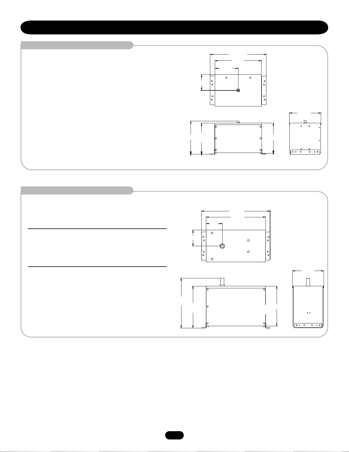
OPERATOR DIMENSIONS AND SPECIFICATIONS
MODEL SW470
• 1/2 HP Motor
Maximum Gate Weight – 500 lbs. (226.8 kg)
Maximum Gate Width – 12 ft. (3.7 m)
MODEL SW490
• 1/2 HP Motor
Maximum Gate Weight – 750 lbs. (340.2 kg)
Maximum Gate Width – 16 ft. (4.9 m)
• 3/4 HP Motor
Maximum Gate Weight – 900 lbs. (408.2 kg)
Maximum Gate Width – 19 ft. (5.8 m)
6.81"
(17.3 cm)
14.25"
(36.2 cm)
7.03"
(17.9 cm)
13.38"
(34 cm)
7.12"
(18.1 cm)
(61.6 cm)
10"
(25.4 cm)
(76.8 cm)
24.25"
20"
(50.8 cm)
30.24"
26.24"
(66.7 cm)
13" (33 cm)
13.63"
(34.6 cm)
• 1 HP Motor
Maximum Gate Weight – 1000 lbs. (453.6 kg)
Maximum Gate Width – 22 ft. (6.7 m)
22"
(55.9 cm)
18.5"
(47 cm)
17.63"
(44.8 cm)
13.75"
(35 cm)
3
3
Page 4
Moving Gate Can Cause
Injury or Death
KEEP CLEAR! Gate may move at any
time without prior warning.
Do not let children operate the gate or
play in the gate area.
This entrance is for vehicles only.
Pedestrians must use separate entrance
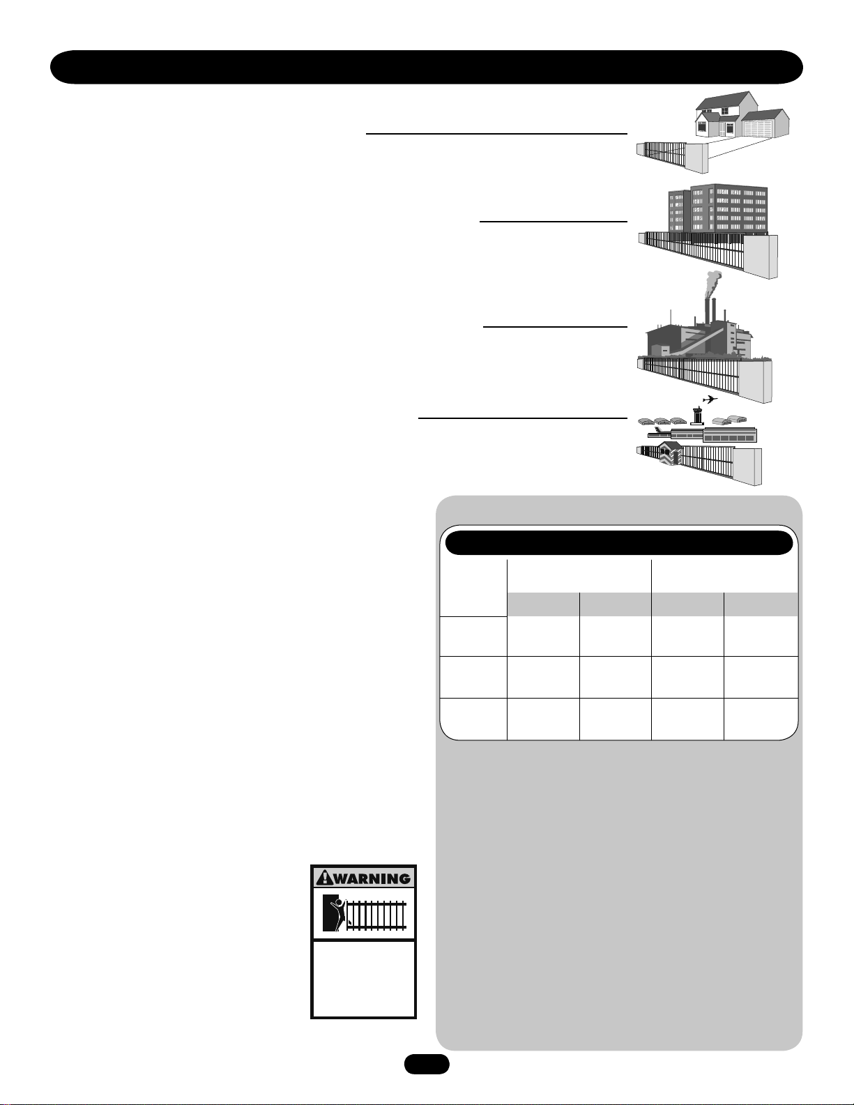
UL325 MODEL CLASSIFICATIONS
The SW470 and SW490 are intended for use with vehicular swing gates. The opener can be used in
Class I, Class II, Class III and Class IV applications.
CLASS I – RESIDENTIAL VEHICULAR GATE OPERATOR
A vehicular gate operator (or system) intended for use in a home of one-to four single family dwellings,
or a garage or parking area associated therewith.
CLASS II – COMMERCIAL/GENERAL ACCESS VEHICULAR GATE OPERATOR
A vehicular gate operator (or system) intended for use in a commercial location or building such as a
multi-family housing unit (five or more single family units) hotel, garage, retail store or other building
servicing the general public.
CLASS III – INDUSTRIAL/LIMITED ACCESS VEHICULAR GATE OPERATOR
A vehicular gate operator (or system) intended for use in a industrial location or building such as a
factory or loading dock area or other location not intended to service the general public.
CLASS IV – RESTRICTED ACCESS VEHICULAR GATE OPERATOR
A vehicular gate operator (or system) intended for use in a guarded industrial location or building such
as an airport security area or other restricted access locations not servicing the general public, in which
unauthorized access is prevented via supervision by security personnel.
SAFETY ACCESSORY SELECTION
All UL325 compliant LiftMaster gate operators will accept external
entrapment protection devices to protect people from motorized
gate systems. UL325 requires that the type of entrapment
protection correctly matches each gate application. Below are the
six types of entrapment protection systems recognized by UL325
for use on this operator.
ENTRAPMENT PROTECTION TYPES
Type A: Inherent obstruction sensing system, self-contained
within the operator. This system must sense and initiate
the reverse of the gate within two seconds of contact
with a solid object.
Type B1: Connections provided for a non-contact device, such as a
photoelectric eye can be used as a secondary protection.
Type B2: Connections provided for a contact sensor. A contact
device such as a gate edge can be used for secondary
protection.
Type C: Inherent adjustable clutch or pressure relief valve.
Type D: Connections provided for a control requiring continuous
pressure to operate the operator
open and close.
Type E: Built-in audio alarm. Examples
include sirens, horns or buzzers.
NOTE: UL requires that all installations must
have warning signs placed in plain view on
both sides of the gate to warn pedestrians of
the dangers of motorized gate systems.
UL325 ENTRAPMENT PROTECTION REQUIREMENTS
GATE OPERATOR ENTRAPMENT PROTECTION
UL325 Slide Gate Operator Swing & Gate Barrier
Installation (Arm) Operator
Class
Class
I & II
Class III
Class IV
Primary
Type
A
A, B1 or B2A, B1, D or
A, B1, B2
or D
Secondary
Type
B1, B2
or D
E
A, B1, B2,
D or E
Primary
Type
A or C
A, B1, B2,
A, B1,
or C
A, B1, C or DA, B1, C, D
The chart above illustrates the entrapment protection
requirements for each of the four UL325 classes.
In order to complete a proper installation you must satisfy the
entrapment protection chart shown above. That means that
the installation must have one primary means of entrapment
protection and one independent secondary means of
entrapment protection. Both primary and secondary
entrapment protection methods must be designed, arranged
or configured to protect against entrapments in both the open
and close directions of gate travel.
For Example: For a slide gate system that is installed on a
single-family residence (UL325 Class I) you must provide the
following: As your primary type of entrapment protection you
must provide Type A- inherent (built into the operator)
entrapment sensing and at least one of the following as your
secondary entrapment protection: Type B1- Non-contact
sensors such as photoelectric eyes, Type B2- Contact sensors
such as gate edges or Type D- Constant pressure control.
4
4
Secondary
Type
C or D
D or E
or E
Page 5
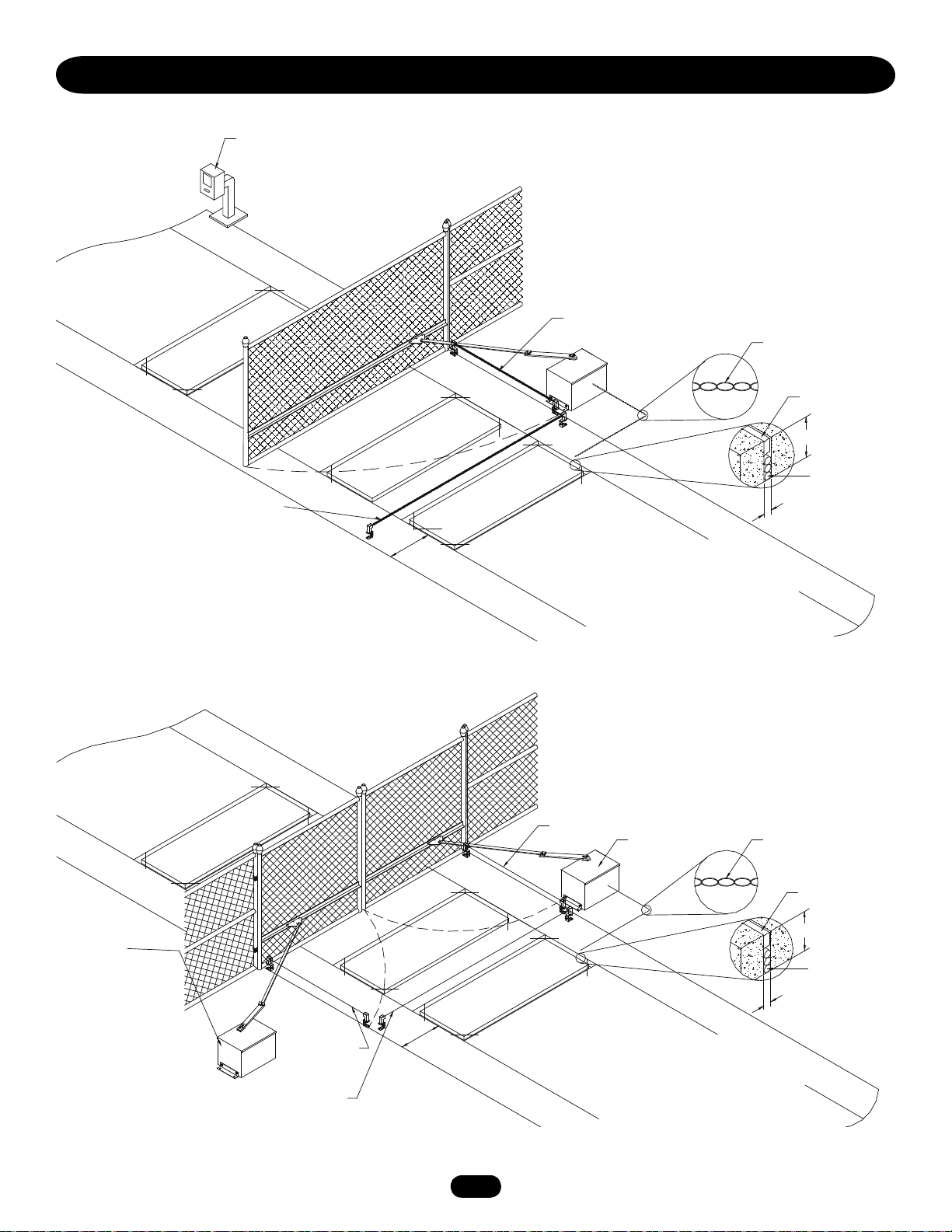
SUGGESTED SAFETY PROTECTION DEVICE LOCATIONS
SWING GATE SYSTEM
STREET
Interrupt (Safety) Loop
Telephone
Entry System
Photo eye for
close cycle
Shadow
Loop
4' (1.2 m)
Typical
Interrupt (Safety) Loop
Photo eye for
open cycle
Run twisted wire*
from loop to
operator
Seal Loops*
1-1/2" (37 mm)
Loop Wire* Layer
1/4" (6 mm) or larger
depending on loop wire
size
COMPLEX
OR
PARKING LOT
DUAL SWING GATE SYSTEM
STREET
Interrupt (Safety)
Loop
Gate 1
Photo eye for
open cycle
Photo eye for
close cycle
Shadow
Loop
4' (1.2 m)
Typical
Interrupt (Safety)
Loop
Photo eye for
open cycle
Gate 2
PARKING LOT
Run twisted wire*
from loop to
operator
Seal Loops*
1-1/2" (37 mm)
Loop Wire* Layer
1/4" (6 mm) or larger
depending on loop wire
size
COMPLEX
OR
* REFER TO LOOP MANUFACTURER’S INSTRUCTIONS FOR DETAILED INSTALLATION & LOOP WIRING INSTRUCTIONS.
55
Page 6

SAFETY INSTALLATION INFORMATION
1. Vehicular gate systems provide convenience and security. Gate systems are comprised of many component parts. The gate
operator is only one component. Each gate system is specifically designed for an individual application.
2. Gate operating system designers, installers and users must take into account the possible hazards associated with each individual
application. Improperly designed, installed or maintained systems can create risks for the user as well as the bystander. Gate
systems design and installation must reduce public exposure to potential hazards.
3. A gate operator can create high levels of force in its function as a component part of a gate system. Therefore, safety features must
be incorporated into every design. Specific safety features include:
• Gate Edges • Guards for Exposed Rollers • Photoelectric Sensors
• Screen Mesh • Vertical Posts • Instructional and Precautionary Signage
4. Install the gate operator only when:
a. The operator is appropriate for the construction and the usage class of the gate.
b. All openings of a horizontal slide gate are guarded or screened from the bottom of the gate to a minimum of 4' (1.2 m) above
the ground to prevent a 2 1/4" (6 cm) diameter sphere from passing through the openings anywhere in the gate, and in that
portion of the adjacent fence that the gate covers in the open position.
c. All exposed pinch points are eliminated or guarded, and guarding is supplied for exposed rollers.
5. The operator is intended for installation only on gates used for vehicles. Pedestrians must be supplied with a separate access
opening. The pedestrian access opening shall be designed to promote pedestrian usage. Locate the gate such that persons will not
come in contact with the vehicular gate during the entire path of travel of the vehicular gate.
6. The gate must be installed in a location so that enough clearance is supplied between the gate and adjacent structures when
opening and closing to reduce the risk of entrapment. Swinging gates shall not open into public access areas.
7. The gate must be properly installed and work freely in both directions prior to the installation of the gate operator.
8 Controls intended for user activation must be located at least six feet (6') away from any moving part of the gate and where the
user is prevented from reaching over, under, around or through the gate to operate the controls. Outdoor or easily accessible
controls shall have a security feature to prevent unauthorized use.
9. The Stop and/or Reset (if provided separately) must be located in the line-of-sight of the gate. Activation of the reset control shall
not cause the operator to start.
10. A minimum of two (2) WARNING SIGNS shall be installed, one on each side of the gate where easily visible.
11. For a gate operator utilizing a non-contact sensor:
a. Reference owner’s manual regarding placement of non-contact sensor for each type of application.
b. Care shall be exercised to reduce the risk of nuisance tripping, such as when a vehicle trips the sensor while the gate is
still moving.
c. One or more non-contact sensors shall be located where the risk of entrapment or obstruction exists, such as the perimeter
reachable by a moving gate or barrier.
12. For a gate operator utilizing a contact sensor such as an edge sensor:
a. One or more contact sensors shall be located where the risk of entrapment or obstruction exists, such as at the leading edge,
trailing edge and post mounted both inside and outside of a vehicular horizontal slide gate.
b. One or more contact sensors shall be located at the bottom edge of a vehicular vertical lift gate.
c. A hard wired contact sensor shall be located and its wiring arranged so the communication between the sensor and the gate
operator is not subject to mechanical damage.
d. A wireless contact sensor such as the one that transmits radio frequency (RF) signals to the gate operator for entrapment
protection functions shall be located where the transmission of the signals are not obstructed or impeded by building structures,
natural landscaping or similar obstruction. A wireless contact sensor shall function under the intended end-use conditions.
e. One or more contact sensors shall be located on the inside and outside leading edge of a swing gate. Additionally, if the bottom
edge of a swing gate is greater than 6" (152 mm) above the ground at any point in its arc of travel, one or more contact sensors
shall be located on the bottom edge.
f. One or more contact sensors shall be located at the bottom edge of a vertical barrier (arm).
6
6
Page 7
GATE CONSTRUCTION INFORMATION
Vehicular gates should be installed in accordance with ASTM F2200: Standard Specification for Automated Vehicular Gate Construction.
For a copy, contact ASTM directly at 610-832-9585 or www.astm.org.
1. GENERAL REQUIREMENTS
1.1 Gates shall be constructed in accordance with the provisions
given for the appropriate gate type listed, refer to ASTM
F2200 for additional gate types.
1.2 Gates shall be designed, constructed and installed to not fall
over more than 45 degrees from the vertical plane, when a
gate is detached from the supporting hardware.
1.3 Gates shall have smooth bottom edges, with vertical bottom
edged protrusions not exceeding 0.50 inches (12.7 mm)
when other than the exceptions listed in ASTM F2200.
1.4 The minimum height for barbed tape shall not be less than 8
feet (2.44 m) above grade and for barbed wire shall not be
less than 6 feet (1.83 m) above grade.
1.5
An existing gate latch shall be disabled when a manually
operated gate is retrofitted with a powered gate operator.
1.6 A gate latch shall not be installed on an automatically
operated gate.
1.7 Protrusions shall not be permitted on any gate, refer to ASTM
F2200 for Exceptions.
1.8 Gates shall be designed, constructed and installed such that
their movement shall not be initiated by gravity when an
automatic operator is disconnected.
1.9 A pedestrian gate shall not be incorporated into a vehicular
gate panel or that portion of the adjacent fence that the gate
covers in the open position.
3.1.4 Positive stops shall be required to limit travel to the
designed fully open and fully closed positions. These stops
shall be installed at either the top of the gate, or at the
bottom of the gate where such stops shall horizontally or
vertically project no more than is required to perform their
intended function.
3.1.5 All gates shall be designed with sufficient lateral stability to
assure that the gate will enter a receiver guide, refer to
ASTM F2200 for panel types.
3.2 The following provisions shall apply to Class IV vehicular
horizontal slide gates:
3.2.1 All weight bearing exposed rollers 8 feet (2.44 m), or less,
above grade shall be guarded or covered.
3.2.2 Positive stops shall be required to limit travel to the
designed fully open and fully closed positions. These stops
shall be installed at either the top of the gate, or at the
bottom of the gate where such stops shall horizontally or
vertically project no more than is required to perform their
intended function.
2. SPECIFIC APPLICATIONS
2.1 Any non-automated gate that is to be automated shall be
upgraded to conform to the provisions of this specification.
2.2 This specification shall not apply to gates generally used for
pedestrian access and to vehicular gates not to be
automated.
2.3 Any existing automated gate, when the operator requires
replacement, shall be upgraded to conform to the provisions
of this specification in effect at that time.
3. VEHICULAR HORIZONTAL SLIDE GATES
3.1 The following provisions shall apply to Class I, Class II and
Class III vehicular horizontal slide gates:
3.1.1 All weight bearing exposed rollers 8 feet (2.44 m), or less,
above grade shall be guarded or covered.
3.1.2 All openings located between 48 inches (1.22 m) and 72
inches (1.83 m) above grade shall be designed, guarded or
screened to prevent a 4 inch
(102 mm) diameter sphere from passing through the
openings anywhere in the gate, and in that portion of the
adjacent fence that covers in the open position.
3.1.3 A gap, measured in the horizontal plane parallel to the
roadway, between a fixed stationary object nearest the
roadway, (such as a gate support post) and the gate frame
when the gate is in either the fully open position or the
fully closed position, shall not exceed 2-1/4 inches
(57 mm), refer to ASTM F2200 for Exception.
4. VEHICULAR HORIZONTAL SWING GATES
4.1 The following provisions shall apply to Class 1, Class II
and Class III vehicular horizontal swing gates:
4.1.1 Gates shall be designed, constructed and installed so as
not to create an entrapment area between the gate and
the supporting structure or other fixed object when the
gate moves toward the fully open position, subject to the
provisions in the 4.1.1.1 and 4.1.1.2.
4.1.1.1 The width of an object (such as a wall, pillar or column)
covered by a swing gate when in the open position shall
not exceed 4 inches (102 mm), measured from the
centerline of the pivot point of the gate, refer to ASTM
F2200 for exception.
4.1.1.2 Except for the zone specified in Section 4.1.1.1, the
distance between a fixed object such as a wall, pillar or
column, and a swing gate when in the open position shall
not be less than 16 inches (406 mm), refer to ASTM
F2200 for exception.
4.2 Class IV vehicular horizontal swing gates shall be
designed, constructed and installed in accordance with
security related parameters specific to the application in
question.
7
Page 8
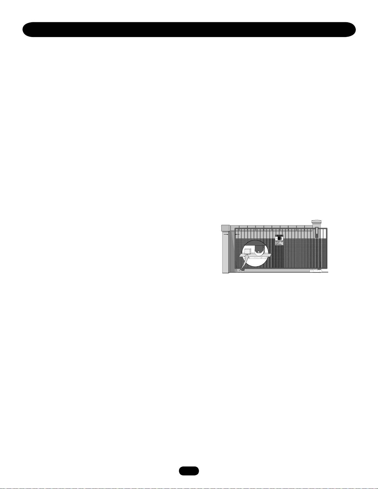
Moving Gate Can Cause
Injury or Death
KEEP CLEAR! Gate may move at any
time without prior warning.
Do not let children operate the gate or
play in the gate area.
This entrance is for vehicles only
Pedestrians must use separate entrance
SAFETY PRECAUTIONS FOR SWING AND
WARNING WARNING
WARNING
WARNING WARNING
WARNING
ORNAMENTAL "GRILL TYPE GATES"
To prevent SERIOUS INJURY or DEATH from a moving gate:
• Entrapment protection devices MUST be installed to protect
anyone who may come near a moving gate.
• Locate entrapment protection devices to protect in BOTH the
open and close gate cycles.
• Locate entrapment protection devices to protect between
moving gate and RIGID objects, such as posts.
• A swinging gate shall NOT open into public access ways.
WARNING SIGN PLACEMENT
To prevent SERIOUS INJURY or DEATH from a moving gate:
• Install warning signs on EACH side of gate in PLAIN VIEW.
• Permanently secure each warning sign in a suitable manner
using fastening holes.
8
8
Page 9
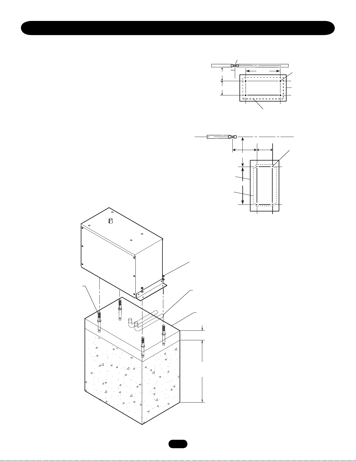
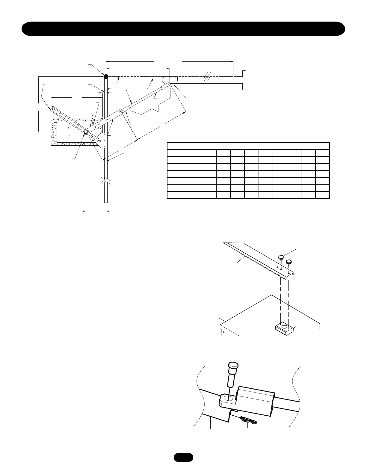
INSTALLATION
POST MOUNTING (SW470)
1. Locate and anchor two posts made of 3" (7.6 cm) outer
diameter heavy walled pipe. Posts should be parallel and
square to the gate.
IMPORTANT NOTE: The distance between mounting posts and
the relative location of the operator to the gate and fence is
critical.
2. Locate electrical conduit, as required, prior to pouring concrete.
3. Set mounting post and electrical conduit in place (Figure 2).
Knockouts for 3" pipe clamps (not supplied) are provided in the
operator.
Figure 2
Figure 1
18.5"
30"
9.5"
Parallel Mount
20"
23"
Fence
Fence
23"
Concrete pad
16 x 32 minimum
3" O.D. pipe
(2 req’d.)
Concrete pad
16 x 32 minimum
Operator
3" O.D. pipe
(2 req’d.)
Operator
3" U-bolt
(4 required)
Perpendicular Mount
Power and control wiring should
be run in separate conduit
9
Page 10
c
INSTALLATION
PAD MOUNTING (SW470)
1. Layout the concrete pad (Figure 1).
IMPORTANT NOTE: The relative location of the operator to the
fence and the gate is critical. Be sure that the measurements for
operator mounting are taken from the centerline of the fence and
of the gate hinge.
2. Locate electrical conduit, as required, prior to pouring concrete.
3. Pour concrete pad.
4. Bolt the (2) pad mount brackets to the bottom of the operator
with the hardware provided.
5. Secure the operator to the concrete pad. It is very important
that the operator be level and square to the gate.
Figure 2
Figure 1
24"
8"
Gate
Concrete pad
18"x34" min.
Profile of
Operator
SW470
Perpendicular
Hinge Pin
9-3/4"
Parallel Mount
18-3/4"
22-1/2"
22-1/2"
Operator
Centerline
8"6"
Fence
1/2" Redhead
(4 required.)
Concrete pad 18"x34" min.
8"16"1/2" Redhead
(4 required)
1/2" red head bolts or
anchors (4 required)
Perpendicular Mount
Using suitable hardware secure
operator to L-bolts
Power and control wiring should be
run in separate conduit
Concrete Pad
2" to 4" above grade
Depth required by
local codes or below
frost line
10
10
Page 11
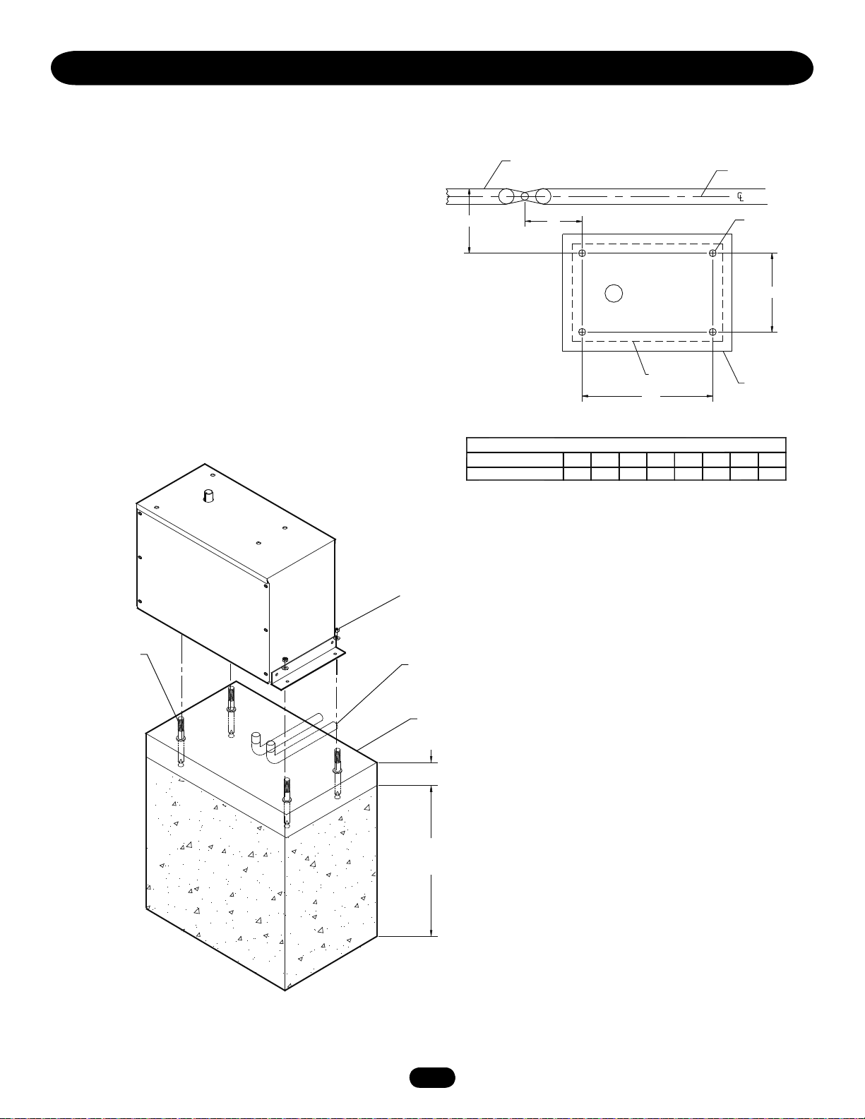
INSTALLATION
PAD MOUNTING (SW490)
1. Measure the gate length and select appropriate “P” dimension
from the gate installation table.
2. Layout the concrete pad as detailed in Figure 1.
IMPORTANT NOTE: The relative location of the operator to the
fence and the gate is critical. Be sure that the measurements for
operator mounting are taken from the centerline of the fence and
of the gate hinge.
3. Locate electrical conduit, as required, prior to pouring concrete.
4. Pour concrete pad.
5. Bolt the (2) pad mount brackets to the bottom of the operator
with the hardware provided (Install the operator so that the
output shaft is on the side closest to the gate).
6. Secure the operator to the pad. It is very important that the
operator be level and square to the gate.
Figure 2
Figure 1
P
GATE LENGTH (FEET)
P DIMENSION IN INCHES
Gate
5"
Output
Shaft
Operator
28"
SW490 GATE OPERATOR INSTALLATION TABLE
8-9 10-11 12-13 14-15 16-17 18-19 20-21 22
21.9 25.3 28.8 32.3 35.7 39.2 42.7 46.1
Fence
1/2" Redhead
(4 Required)
8"
Concrete Pad
18" x 34" min.
1/2" red head bolts or
anchors (4 required)
Using suitable hardware secure
operator to L-bolts
Power and control wiring should be
run in separate conduit
Concrete Pad
2" to 4" above grade
Depth required by
local codes or below
frost line
11
11
Page 12
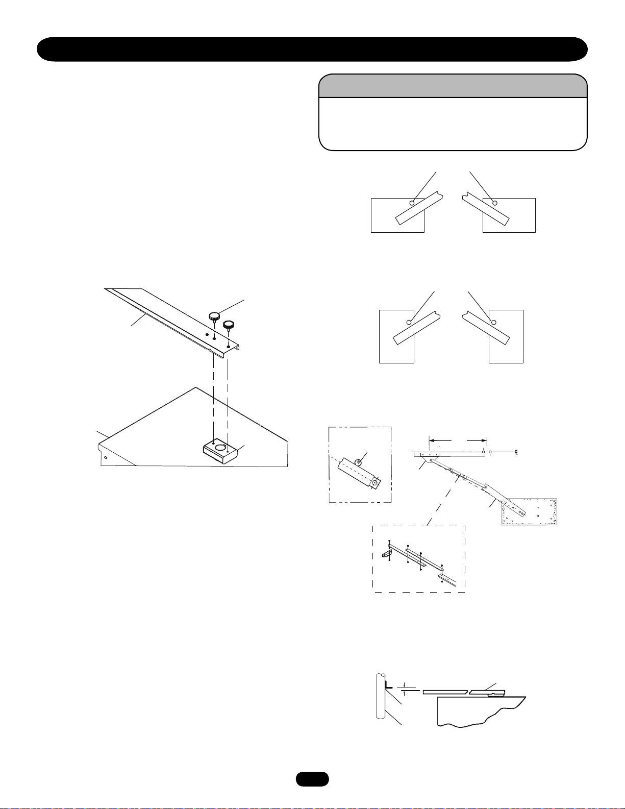
INSTALLATION
WARNING
CAUTION CAUTION
WARNING
WARNING
Model SW470
CONTROL ARM ASSEMBLY (SW470)
1. Set the control arm stop on the operator in the positions
appropriate for the installation (Figure 1).
2. Install the arm channel to the hub assembly to the operator
output shaft.
3. Secure the arm channel to arm hub with 1/4-20 black plastic
knobs provided (Hub is factory installed - Figure 2).
4. Assemble extension arm to control arm. Be sure to keep the
extension arm with spot-faced side up. Use the holes that are
appropriate for desired degree of gate opening. The extension
arm should swivel easily on pivot screws when the nuts are
tightened. Attach the other end of the actuator arm to the gate
brackets (Figure 3).
If the arm stop is installed incorrectly, the gate will be
prevented from opening and damage to the operator may
result!
Figure 1
Left hand
installation
Close Stops
Right hand
installation
SW470 Parallel to Fence
Figure 2
Housing
Arm Channel
Black Plastic
Knob
Hub
Assembly
Figure 3
Eccentric stop during
installation of gate
plate
Installation Detail
Close Stops
“L.H.”
“R.H.”
SW470 Perpendicular to Fence
36"
Gate
Plate
Crank Extension
Extension arm
installation detail
Hinge Pin
Eccentric stop (operating position
after adjustment). Arm must
swing approximately 2 degrees
past straight position (See detail)
NOTE: Dotted line indicates
straight arm position
GATE BRACKET INSTALLATION (SW470)
1. Install gate bracket (supplied) or install an angle (2" x 2" x 1/4"
by others) horizontally on gate, at the same height as the top
surface of the control arm extension (see figure to the right).
2. Adjust the eccentric stop as shown so that the wide area of the
eccentric stop is against the arm. Be sure that the control arm
and actuator are in a straight line. Install the gate bracket and if
required install an angle (for SW490 2" x 2" x 1/4" by others) at
the appropriate point on the gate in reference to gate hinge pin.
NOTE: As an alternative, (2) 3/8-16 bolts and a nut plate are
provided. Adjust arm length and then rotate the eccentric stop
180 degrees so that the small thickness is against the arm. This
will provide the necessary deflection in the arm assembly to lock
the gate.
12
12
Top of gate bracket should be mounted 1/2"
higher than top of arm channel
Arm Channel
Gate
Bracket
Gate
Page 13
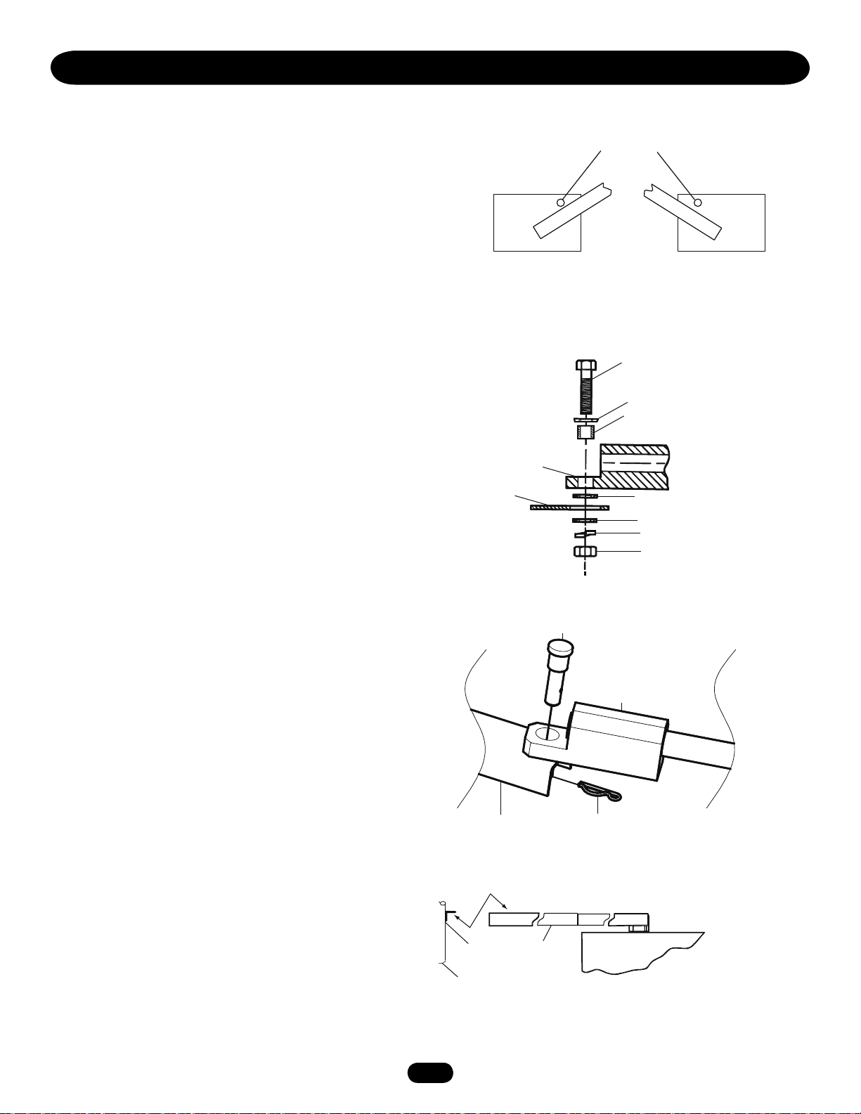
INSTALLATION
MODEL SW490
2"x2"x1/4"
angle
(by others)
gate
Control arm
extension
CONTROL ARM ASSEMBLY (SW490)
1. Set the control arm’s close stop on the operator so that its
position corresponds with the handling of the installation
(Figure 1).
2. Remove the open stop, as it is not to be used in this
application. Use any existing hardware necessary to seal the
open stop’s hole in the operator’s cover.
3. Measure the length of the gate panel and select the appropriate
extension arm (x) and control arm (Y) dimensions from the
gate installation table.
4. Install the control arm hub assembly to the operator’s output
shaft. Make sure that the key is properly inserted into the hub
assemblies keyway. Lock the key in place with using the set
screw provided in the hub.
5. Attach control arm extension to control arm hub assembly by
bolting or welding the two pieces together to achieve the
proper control arm dimension (Y).
6. Determine the proper location of the gate bracket by measuring
the gate panel’s length and referring to the gate installation
table (Dimension B) on the next page. Install the supplied gate
bracket or install your own gate bracket (recommended
2" x 2" x 1/4" angle) horizontally on the gate and at the same
height as the top surface of the control arm extension. Secure
the gate bracket to the gate by either welding or bolting the
bracket to the gate.
7. Assemble one extension arm holder to the gate bracket using
supplied hardware (Figure 2).
8. Assemble the other extension arm holder to the control arm
extension using the supplied pivot pin assembly and cotter pin
(Figure 3).
9. Measure and cut pipe (not provided) and position the pipe into
the extension arm holders to achieve the proper extension arm
dimension (X). Insert the hex head set screws in each
extension arm holder in order to hold pipe firmly. Do not
tighten until testing and all final adjustment have been
completed (Figure 4).
Figure 1
Left hand
installation
Figure 2
Extension Arm Holder 3/4"
Gate bracket or
extension arm
Figure 3
Close Stops
Right hand
installation
SW490 Parallel to Fence
3/4"-10 x 3 Hex Head Bolt
3/4" Flat Washer
3/4" Bushing
3/4" Flat Washer
3/4" Flat Washer
Split Lock Washer 3/4"
3/4"-10 Hex Nut
Pivot pin assembly
Extension arm holder
Figure 4
1313
Extension arm
Cotter Pin
Bottom of angle and top of control
arm extension should be level
Control arm
extension
Page 14
INSTALLATION
CONTROL ARM ASSEMBLY (SW490) continued
D
Gate Hinge
Open gate position
34"
Closed gate stop
Control arm hub
assembly
Output Shaft
Gate Length
B
90º
2"
Control arm
extension
C
13"
Closed
gate
position
Extension
Arm Holder
Y
Gate Center Line
Pipe
Extension
Arm
X
Gate Length (Feet) 8-9 10-11 12-13 14-15 16-17 18-19 20-21 22
A Dimension (Inches) 4.5 4.5 4.5 4.5 4.5 4.5 4.5 4.5
B Dimension (Inches) 24 30 36 42 48 54 60 66
C Dimension (Inches) 13 13 13 13 13 13 13 13
D Dimension (Inches) 25.9 29.3 32.8 36.3 39.7 43.2 46.7 50.1
X Dimension (Inches) *25.7 *29 *32.8 *36.9 *41.2 *45.6 *50 *54.6
Y Dimension (Inches) **17 **20.6 **23.8 26.6 29.3 31.8 34.2 36.6
All table dimensions are measured from pivot to pivot.
* Cut/add excess pipe for desired extension arm pivot to pivot dimension.
** Cut excess control arm extension and/or control arm hub assembly for desired pivot to
pivot dimension. Weld or bolt extension arm to arm assembly.
Gate Bracket
SW490 Gate Installation Table
A
4.5"
MANUAL DISCONNECT
MODEL SW470
1. Remove the (2) black knobs securing the control arm to the
operator (Figure 1).
2. Swing arm assembly off to the side. Gate should swing freely.
MODEL SW490
1. Remove hitch pin and pivot pin securing control arm to arm
assembly (Figure 2).
2. Swing arm assembly off to the side. Gate should swing freely.
Figure 1
Figure 2
Black Plastic
Knob
Arm Channel
Housing
Hub
Assembly
Pivot Pin Assembly
Extension Arm Holder
1414
Extension Arm
Cotter Pin
Page 15

WIRING
WARNING
WARNING WARNING
To reduce the risk of SEVERE INJURY or DEATH:
• ANY maintenance to the operator or in the area near the
operator MUST not be performed until disconnecting the
electrical power and locking-out the power via the operator
power switch. Upon completion of maintenance the area
MUST be cleared and secured, at that time the unit may be
returned to service.
• Disconnecting power at the fuse box BEFORE proceeding.
Operator MUST be properly grounded and connected in
accordance with local electrical codes. NOTE: The operator
should be on a separate fused line of adequate capacity.
• ALL electrical connections MUST be made by a qualified
individual.
• DO NOT install any wiring or attempt to run the operator
without consulting the wiring diagram. We recommend that
you Install an optional reversing edge BEFORE proceeding
with the control station installation.
• ALL power wiring should be on a dedicated circuit and well
protected. The location of the power disconnect should be
visible and clearly labeled.
• ALL power and control wiring MUST be run in separate
conduit.
• BEFORE installing power wiring or control stations be sure to
follow all specifications and warnings described below. Failure
to do so may result in SEVERE INJURY to persons and/or
damage to operator.
POWER WIRING INSTALLATION
Wiring Specifications (STRANDED COPPER WIRE)
On a Dual Gate System, each unit must be installed on ITS OWN separate circuit.
WIRE GAUGE 6
• 1/2 HP Motor ------- 425 ft. (129.5 m) 1845 ft. (562.4 m) 2557 ft. (779.4 m) 12789 ft. (3898.1 m) 15987 ft. (4872.8 m)
• 3/4 HP Motor ------- 291 ft. (88.7 m) 1107 ft. (337.4 m) 1827 ft. (556.9 m) 6394 ft. (1948.9 m) 10657 ft. (3248.3 m)
• 1 HP Motor --------- 213 ft. (64.9 m) 852 ft. (259.7 m) 1278 ft. (389.5 m) 5115 ft. (1559.1 m) 7993 ft. (2436.3 m)
115 Vac 230 Vac
SINGLE PHASE
230 Vac 460 Vac 575 Vac
THREE PHASE
WIRE GAUGE 8
• 1/2 HP Motor ------- 269 ft. (82 m) 1165 ft. (355.1 m) 1614 ft. (492 m) 8072 ft. (2460.4 m) 10089 ft. (3075.1 m)
• 3/4 HP Motor ------- 183 ft. (55.8 m) 699 ft. (213.1 m) 1152 ft. (351.1 m) 4035 ft. (1229.9 m) 6726 ft. (2050.1 m)
• 1 HP Motor --------- 134 ft. (40.8 m) 537 ft. (163.7 m) 807 ft. (246 m) 3228 ft. (983.9 m) 5044 ft. (1537.4 m)
WIRE GAUGE 10
• 1/2 HP Motor ------- 168 ft. (51.2 m) 730 ft. (222.5 m) 1012 ft. (308.5 m) 5064 ft. (1543.5 m) 6330 ft. (1929.4 m)
• 3/4 HP Motor ------- 115 ft. (35.1 m) 438 ft. (133.5 m) 723 ft. (220.4 m) 2532 ft. (771.8 m) 4220 ft. (1286.3 m)
• 1 HP Motor --------- 84 ft. (25.6 m) 337 ft. (102.7 m) 506 ft. (154.2 m) 2025 ft. (617.2 m) 3165 ft. (964.7 m)
WIRE GAUGE 12
• 1/2 HP Motor ------- 105 ft. (32 m) 458 ft. (139.6 m) 634 ft. (193.2 m) 3171 ft. (966.5 m) 3964 ft. (1208.2 m)
• 3/4 HP Motor ------- 72 ft. (22 m) 274 ft. (83.5 m) 503 ft. (153.3 m) 1585 ft. (483.1 m) 2643 ft. (805.6 m)
• 1 HP Motor --------- 53 ft. (16.2 m) 211 ft. (64.3 m) 316 ft. (96.3 m) 1269 ft. (386.8 m) 1982 ft. (604.1 m)
NOTE: Calculated using NEC guidelines. Local codes and conditions must be reviewed for suitability of wire installation. All power
wiring should be dedicated and protected. Location of primary power disconnect should be labeled.
1515
Page 16

STOP/RESET BUTTON WIRING
STOP/RESET
1 2 3 4 5 6 7 8 9 10
WIRING
ON/OFF SWITCH POWER WIRING
NOTE: Before running power wiring refer to wiring specifications
on page 15 for correct wire gauges.
Secure all electrical power connections inside the disconnect
switch electrical box. Refer to electrical wiring diagrams on pages
31-33.
IMPORTANT: On three phase operators, power connections must
be properly phased. If phased incorrectly, the gate operator will
run reversed. To correct this situation, shut off power at main
power source and at the operator’s electrical disconnect switch.
Then reverse any two of the three power leads.
SINGLE PHASE
All single phase operators will have the following:
115V 208/230V
• L1 (NEUTRAL), WHITE • L1 (HOT), BLACK
• L2 (HOT), BLACK • L2 (HOT), BLACK
• GROUND, GREEN • GROUND, GREEN
ON/OFF Switch
Cover
Wire Nut Connections
(See Instructions)
THREE PHASE
All three phase operators will have the following:
• L1 BLACK • L2 BLACK
• L3 BLACK • GROUND, GREEN
STOP/RESET BUTTON CONTROL WIRING (REQUIRED)
1. This control will function as a Stop/Reset command and is to
be wired within line of sight of the gate. The operator will not
function unless this circuit is completed.
2. Wire control station to terminals 3 and 5 in the control box on
the operator.
J1 CONNECTOR
Power Wiring Conduit
Control Conduit
STOP/RESET
Button
NOTE: For additional control station options refer to pages
21 and 22.
1616
Page 17
M
M
24V
12V
HIGH
NORM
C
P2
M
ADJUSTMENT
WARNING
WARNING WARNING
WARNING WARNING
WARNING
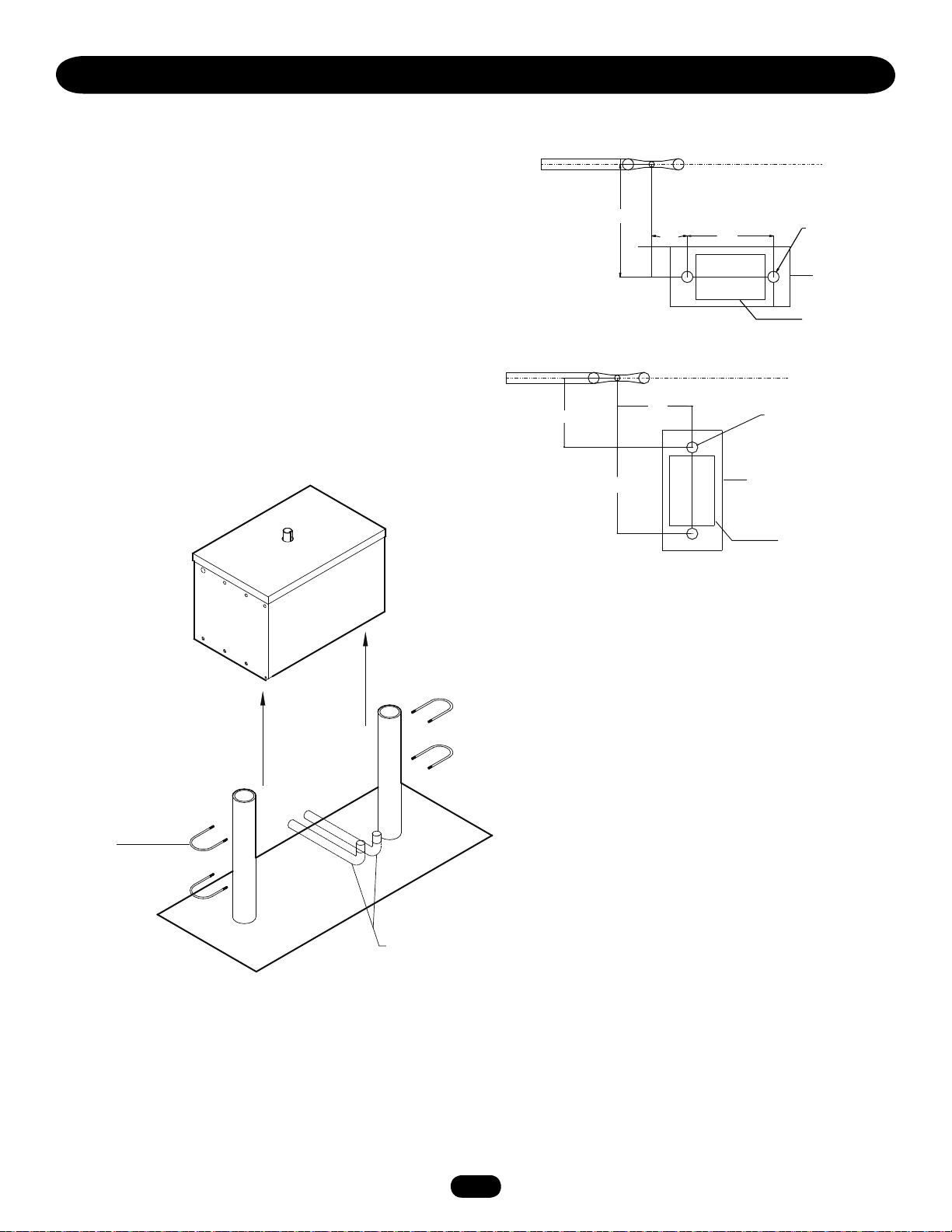
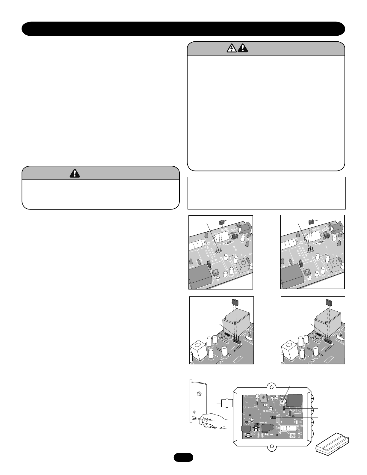
PROGRAMMING THE RADIO RECEIVER
SET SECURITY MODE
The Universal Receiver can be used with up to 15 315 MHz rolling
code remote controls or PINs in HIGH security mode. Alternately,
it can be used with up to 31 of any type 315 MHz remote control
in NORMAL security mode, including any combination of rolling
code, billion code, or dip switch remotes.
The jumper must be set at the HIGH position for the receiver to
operate in HIGH security mode. It must be set at NORMAL
position to operate at the NORMAL mode (Figure 1).
When changing from NORMAL to HIGH security mode, any
previous remote control codes must be erased. Repeat Steps 2
and 3 in the Programming Section below to reprogram the
receiver for each remote control in use.
The receiver is factory set at HIGH.
To prevent possible SERIOUS INJURY or DEATH, the use of
CONSTANT OPERATION on residential openers is
PROHIBITED.
To prevent possible SERIOUS INJURY or DEATH from
electrocution:
• Be sure power is not connected BEFORE installing the
receiver.
To prevent possible SERIOUS INJURY or DEATH from a
moving gate or garage door:
• ALWAYS keep remote controls out of reach of children.
NEVER permit children to operate, or play with remote
control transmitters.
• Activate gate or door ONLY when it can be seen clearly, is
properly adjusted, and there are no obstructions to door
travel.
• ALWAYS keep gate or garage door in sight until completely
closed. NEVER permit anyone to cross path of moving gate
or door.
NOTICE: To comply with FCC and or Industry Canada (IC) rules, adjustment or modifications of
this receiver and/or transmitter are prohibited, except for changing the code setting or replacing
the battery. THERE ARE NO OTHER USER SERVICEABLE PARTS.
Tested to Comply with FCC Standards FOR HOME OR OFFICE USE. Operation is subject to the
following two conditions: (1) this device may not cause harmful interference, and (2) this device
must accept any interference received, including interference that may cause undesired operation.
SET OUTPUT DURATION
For commercial applications, the receiver can be set for either
constant or momentary closure on the output contacts. Use of
constant closure is prohibited on residential garage door openers
because it overrides the safety reversal devices.
With the jumper in the “M” (Momentary) position, the contacts
will close for 1/4 second regardless of the length of radio
transmission. With the jumper in “C” (Constant) position, the
contacts will stay closed as long as the radio continues
transmitting (Figure 2).
The receiver is factory set at M.
PROGRAMMING THE REMOTE TO THE RECEIVER
1. Pry open the front panel of receiver case with a coin or a
screwdriver. Re-connect power to opener (Figure 3).
2. Press and release the “learn” button on the receiver. The learn
indicator light will glow steadily for 30 seconds.
3. Within 30 seconds, press and hold the button on the hand-held
remote that you wish to operate your garage door.
The opener will now operate when the push button on either the
receiver or the remote control is pressed.
Repeat Steps 2 and 3 for each remote control that will be used to
operate the garage door opener.
To erase all remote control codes:
Press and hold the “learn” button on the receiver panel until the
indicator light turns off (about 6 seconds). All remote control
codes are now erased. Then follow the steps above to reprogram
each remote control.
Security Mode
Terminals
CONSTANT
OPERATION
OPENING RECEIVER
17
17
Output
Duration
Terminals
Connect
Antenna
Jumper
SECURITY MODE
Jumper
OPEN RECEIVER
HIGH
Figure 1
Figure 2
Figure 3
Indicator Light
Security Mode
Terminals
MOMENTARY
OPERATION
Output
Duration
Terminals
Learn Button
Jumper
NORMAL
SECURITY MODE
Jumper
Output Duration
Terminals
Security Mode
Power Supply Jumper
Page 18

ADJUSTMENT
WARNING
CAUTION CAUTION
WARNING
WARNING
LIMIT SWITCH ADJUSTMENT
NOTE: For limit location and configuration refer to Figure 1.
1. Before turning on power, disconnect extension arm from
gate bracket so gate is no longer connected to operator.
Push manual release pin(s) up through the control arm, slide
clevis pin in place and secure with a cotter pin.
2. The (3) collars are held to shaft by set screws. The collars
should now be loose on the shaft. If not, loosen all set
screws until collars are moving freely on shaft.
When following limit switch adjustment procedure, the motor
belt will turn and the control arm will move during some
steps. Keep hands and tools out of operator and away from
arm and drive shaft unless power is off or SERIOUS INJURY
may occur.
TO ADJUST CLOSE LIMIT SWITCH
3. Turn on electrical power.
4. Press CLOSE button (if installed) or connect terminals
4 & 5 on J1 terminal strip to cause the gate to close. The
control arm should move in the close direction.
5. When control arm is pointed in approximate direction of gate
bracket (on fully closed gate) press STOP button or release
terminals to stop control arm.
NOTE: If control arm does not move far enough to point in proper
direction, the close limit switch has been prematurely actuated.
Turn off power, loosen set screw on close limit cam and rotate
nut away from close limit switch. Repeat steps 3 and 4 until
control arm is pointed in correct direction.
6. Turn off power. Be sure close limit cam is freely turning.
Rotate cam in close direction. Stop when cam just clicks
close limit switch. Tighten set screw.
7. Reconnect gate bracket to extension arm. If arm has moved
too far in close direction to allow connection of gate bracket
turn off power, connect terminals 5 & 7 to rotate arm in
opposite direction, and press STOP button when arm is in
desired position.
TO ADJUST OPEN LIMIT SWITCH
8. Turn on power. Press OPEN button (if installed) or connect
terminals 5 & 7 on J1 terminal strip. Gate should open. If
gate does not open the open limit cam may be already
actuating open limit switch or an improper electrical
connection may have been made. Turn off power, inspect,
correct and repeat this step.
9. When gate reaches desired fully open position press STOP
button or release terminals. Turn off power. Limit cam
should turn freely. Rotate cam in open direction. Stop when
cam just clicks the open limit switch. Tighten set screw.
10. Fine tune both switch settings by using J1 terminals 4 & 5
(to CLOSE) of 5 & 7 (to OPEN) and the factory supplied
STOP button to move gate and rotating limit collars slightly
to alter gate travel. Rotate cam away from limit switch to
increase travel, toward switch to decrease travel.
Drive Shaft
Set Screw
Aux switch (optional)
Limit Switch “A”
Limit Switch “B”
LIMIT DIRECTION
DIRECTION OF
GATE TO OPEN
RIGHT
(Factory Default)
LEFT
OPEN
LIMIT
A
B
Limit Switch
Limit Cam
CLOSE
LIMIT
B
A
18
18
Page 19
ADJUSTMENT
WARNING WARNING
WARNING
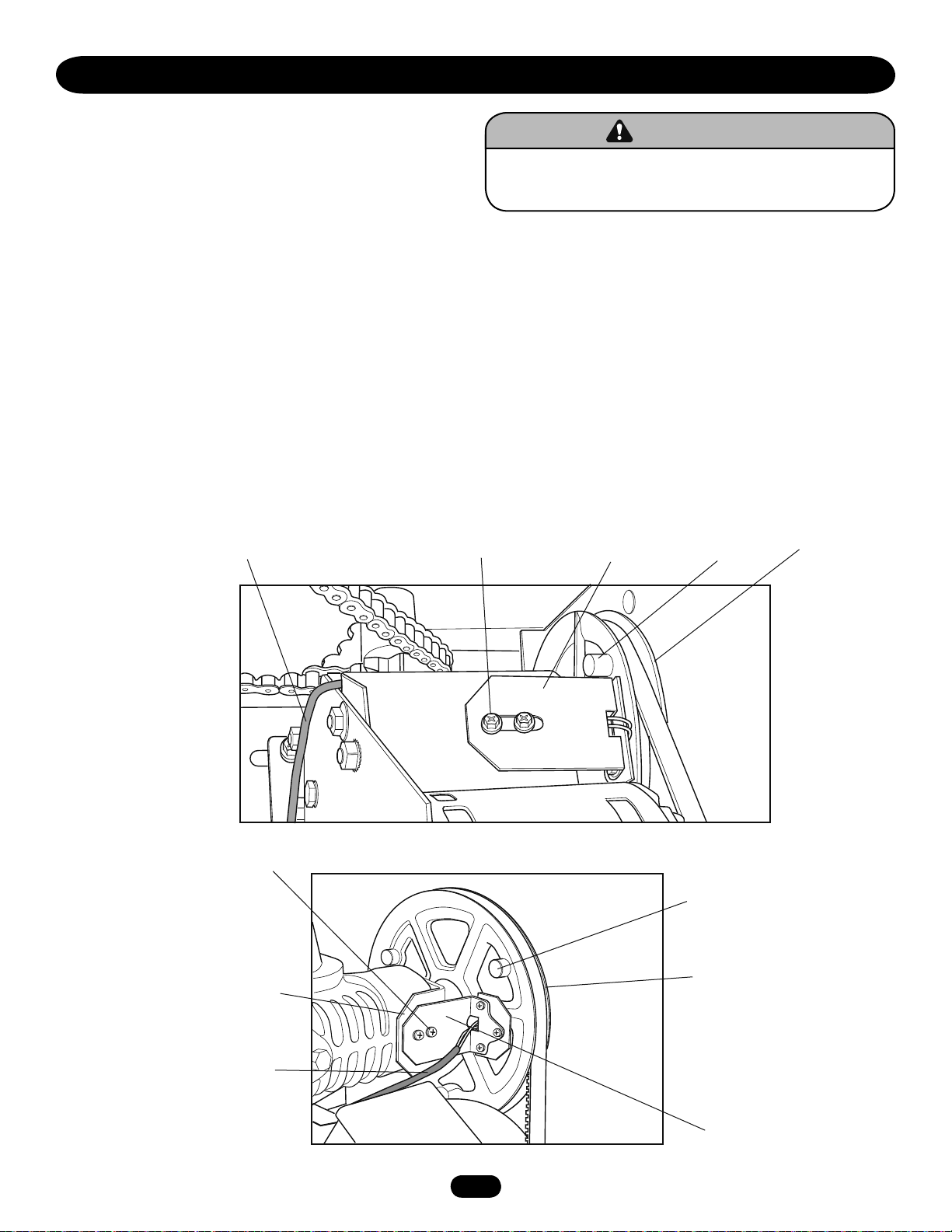
RPM SENSOR (HALL EFFECT) ADJUSTMENT
NOTE: Normally the RPM sensor (hall effect) does not need
adjustment, but may go out of alignment due to shipping
vibration or rough handling.
These operators use an internal entrapment protector system.
This system consists of the control board, magnet, and RPM
sensor. It may become necessary to adjust the sensor for correct
alignment. To do so, please perform the following steps:
1. Loosen the two screws holding the hall bracket to the frame.
2. Adjust the bracket so that the sensor is:
a. Parallel with the pulley.
b. .020" (.051 cm) away from the pulley's magnet. Use a
feeler gauge to measure the distance.
3. Tighten screws to secure assembly.
4. Manually rotate pulley to ensure that each magnet clears the
sensor board.
If a magnet does not clear the board, re-adjust the RPM
(hall effect) assembly accordingly.
To reduce the risk of SEVERE INJURY or DEATH:
• Disconnect power BEFORE performing ANY adjustments.
MODEL SW470
MODEL SW490
Hall Effect Cable
Mounting
Screw (2)
Mounting
Bracket
Mounting
Screw (2)
Hall Effect
Bracket
Pulley
Magnet
Pulley
Magnet
Pulley
Pulley
Hall Effect Cable
Hall Effect
Magnet
1919
Page 20
ADJUSTMENT
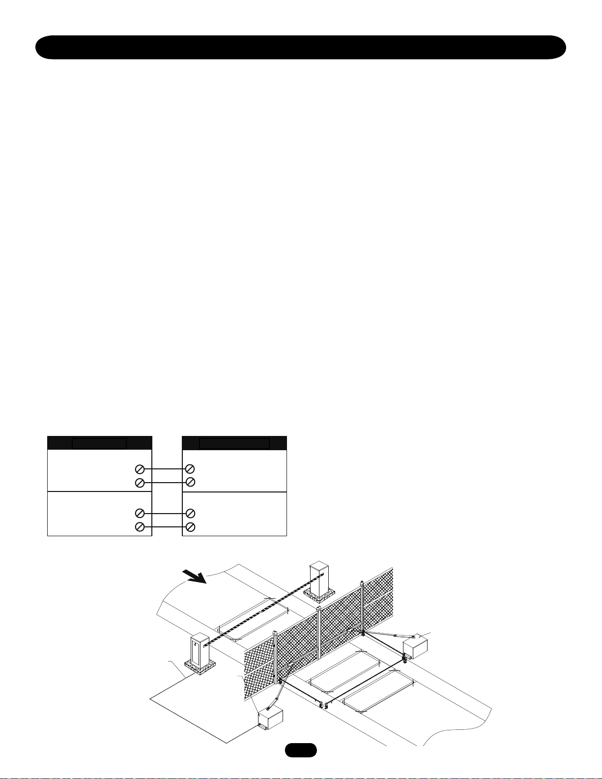
SEQUENCED ACCESS MANAGEMENT SYSTEM (SAMS)
The Sequenced Access Management System or SAMS allows the
customer more control when managing vehicular entrances to
areas such as apartment complexes, businesses and gated
communities. The basic concept of the system is that traffic is
controlled by two gates installed in tandem, a fast moving gate
such as a barrier gate operator and a slower moving more secure
or ornamental gate such as a single or pair of slide/swing gate
operator. The design of this gate system balances the demands of
speed during high traffic periods with security during low traffic
periods. Barrier gates typically have the fastest open times of the
many gate operator types and the slide or swing gates allow you
to effectively seal off the perimeter of the complex you are
planning to secure.
NOTE: Connect all entry devices to the slide or swing gate. If
using a device, such as a 7-day timer, to latch the slide or swing
gate open during high traffic times, connect the device’s N/O relay
output to the control board’s Interrupt Loop input. Once the
device activates the Interrupt Loop input, the next vehicle to
access the SAMS system will lock the gate in the open position
until the device deactivates. When the device deactivates, the
timer to close will automatically close and secure the gate.
SAMS OPERATION
1. When an authorized vehicle accesses the gate system, the SAM
system responds by first opening the gate farthest from the
vehicle, the swing or slide gate.
2. Once the swing or slide gate is open, the barrier gate begins its
open cycle.
TERMINAL BLOCK
INTERRUPT LOOP INPUT AUXILIARY LIMIT SWITCH
TB5
TB8
SAMS RELAY AT J5 TERMINAL STRIP
N/0
COM
BG770 BARRIER GATE
N/0
COM
1 (OPEN)
3 (COMMON)
3. Once the barrier is open the vehicle may pass through the SAM
system. At this point you have two options in how you would
like to initiate the SAM systems closure. You may chose to:
a. Use a timer to close system to automatically close the
barrier gate after a preset amount of time or
b. Use a loop system to close the barrier gate after the vehicle
has passed through the SAM system.
4. Once the barrier gate is closed the slide or swing gate will
activate its internal timer to close and begin closing.
5. If another authorized vehicle accesses the SAM system before
the slide or swing begins to close the barrier will open and
allow the vehicle to pass through the SAM system.
6. If another authorized vehicle accesses the SAM system during
the slide or swing gates closing cycle the SAM system will
reopen the slide or swing gate. Once the slide or swing gate
reaches the open position the barrier will then open to allow
the vehicle to pass through the SAM system.
7. If no other authorized vehicles access the SAM system the
swing or slide gate will close followed by the barrier.
SAMS WIRING
1. Install conduit between the BG770 and the SW420 for SAMS
control wiring.
2. Run a 4-conductor cable in the conduit between the BG770
SW420.
3. Locate the SAMS relay terminals (J5) on the control board in
the SW420 and locate the auxiliary limit switch in the BG770.
4. Attach a wire from the SAMS relay terminal (J5) on the control
board to terminal 1 on the BG770 terminal strip.
5. Attach a wire from the SAMS relay terminal (J5) on the control
board to terminal 3 on the BG770 barrier gates terminal strip.
6. Attach a wire from terminal J1-5 on the control board to the
common (COM) on the auxiliary limit switch in the barrier gate.
7. Attach a wire from terminal J1-8 on the control board to the
normally open (NO) on the auxiliary limit switch.
8. Test for correct functionality of the SAM system.
SAMS Conduit
TRAFFIC
STREET
Second
Hold Open Loop
2020
Shadow Loop
Safety Loop
Master
COMPLEX
OR
PARKING LOT
Page 21

SOFT OPEN
1 2 3 4 5 6 7 8 9 10
INTERRUPT (SAFETY) LOOP INPUT
5 8 9 10 11 12
12345678910111213141516
R2
R1
R4
R3
24 Vac
FREQ
FREQ
FREQ
3
6
9
#
2
5
8
0
1
7
ADJUSTMENT
ONE BUTTON WIRING
1 2 3 4 5 6 7 8 9 10
SHADOW LOOP INPUT
1 2 3 4 5 6 7 8 9 10
ACCESSORY WIRING
All inputs are normally open and momentary, except the stop
(N.C.). The following instructions are based upon UL325, and
include recommendations for significant increase in safety.
We strongly recommend that you follow the UL guidelines
presented throughout the manual. Refer to instructions shipped
with optional control devices for mounting, wiring, programming
and adjustment.
24 Vac Accessory Power
Can be found at terminals R1 and R2 located on radio terminal
block.
J1 Terminal Block
Control Board
J1 Terminals 1 & 5 - Residential Radio (single button) Input
These terminals are intended for use with a radio receiver in a
residential application or as a single button control. This allows
the user to open the gate by activating the remote control when
the gate is closed or between limits. This input also gives the user
the ability to close the gate by activating the remote control when
the gate is on the open limit.
J1 Terminals 2 & 5 - Shadow Loop Input
These terminals are intended for use with a loop detector and is
primarily used on swing gate operators. This input protects cars
by preventing the gate from moving off of the open or close limit
when the shadow loop input is active.
J1 Terminals 6 & 5 - Soft Open
These terminals are intended for use as a general open control.
Accessories that may be wired to this input include: Telephone
Entry Systems, Radio Receiver (Commercial Applications), Exit
Loop Detector, Keypads, 7-Day Timer.
NOTE: Will not override a double entrapment (signalled by the
gate stopped and entrapment alarm on).
Field Wiring Terminals 8 & 5 - Interrupt (Safety) Loop Input
These terminals are intended for use with a loop detector. This
input functions to reverse a closing gate to the open limit.
Latching this input will reset the timer to close.
21
21
Page 22

OP
E
N
CL
O
SE
ST
O
P
OP
E
N
CL
O
SE
ST
O
P
O
P
E
N
CL
O
SE
ST
O
P
ADJUSTMENT
OBSTRUCTION OPEN (EDGE/PHOTO EYE INPUT)
5 8 9 10 11 12
OBSTRUCTION CLOSE (EDGE/PHOTO EYE INPUT)
5 8 9 10 11 12
STOP/RESET BUTTON WIRING
R1 R2 R3 R4 3 5
HARD CLOSE CONTROL INPUT
1 2 3 4 5 6 7 8 9 10 11 12 13 14 15 16
HARD OPEN CONTROL INPUT
1 2 3 4 5 6 7 8 9 10 11 12 13 14 15 16
ACCESSORY WIRING
Field Wiring Terminals 9 & 5 - Obstruction Open
(Edge/Photo Eye Input)
Edge Input: See Programming Section
This input will reverse an opening gate to the close limit.
Activating this input when the gate is closing will have no effect.
NOTE: If upon reversal a second separate obstruction is detected
(gate edge or RPM sensor), gate will stop and alarm.
Photo Eye Input: See Programming Section
This input will pause an opening gate. Once the input (photo eye)
is cleared, the gate continues to open. Activating this input when
the gate is closing will have no effect.
Field Wiring Terminals 10 & 5 - Obstruction Close
(Edge/Photo Eye Input)
Edge Input: See Programming Section
This input will reverse a closing gate to the open limit. When
reaching the open limit the Timer to-Close, if enabled, will be
disabled until another command is given. Activating this input
when the gate is closing will have no effect. NOTE: If upon
reversal a second separate obstruction is detected (gate edge or
RPM sensor), gate will stop and alarm.
Photo Eye Input: See Programming Section
This input will reverse a closing gate to the open limit. This input
will not affect the Timer-to-Close. Activating this input when the
gate is closing will have no effect.
Field Wiring Terminals 3 & 5 - Stop/Reset Control Input
These terminals are intended for use with a single stop/reset
button or the stop control of a three-button station that is
installed within line of site of the gate. This input functions to
stop the gate or to reset the gate after an entrapment fault.
NOTE: This input uses a normally closed circuit and the operator
will not run until a stop control is installed.
J1 Terminals 4 & 5 - Hard Close Control Input
These terminals are intended for use only with the close control
of a three-button station that is installed within line of sight of the
gate. A momentary activation of this input will cause the gate to
close. Activation of this input for longer than three seconds will
enable the control to be used as a constant pressure override
device. This will allow the user, in emergencies, to override a
failed accessory such as a loop detector or photo-eye.
J1 Terminals 7 & 5 - Hard Open Control Input
These terminals are intended for use only with the open control of
a three-button station that is installed within line of sight of the
gate. A momentary activation of this input will cause the gate to
open. Activation of this input for longer than three seconds will
enable the control to be used as a constant pressure override
device. This will allow the user, in emergencies, to override a
failed accessory such as a loop detector or photo eye.
STOP
CLOSE
OPEN
22
Page 23

CONTROL BOARD ILLUSTRATION
J4 Connector
Master/Second
Main Terminal
Wiring
J2 Connector
Dip Switch #4
Master/Second
Potentiometer Timer-to-Close
Potentiometer Force
Adjustment
Dip Switch #2
Dip Switch #1
Diagnostic LED
Limit LEDs
J5 Connector
SAMS
Relay Drive
Troubleshooting LEDs
J1 Terminal
Troubleshooting LEDs
Programming Port
(factory use only)
Motor Learn
Button
J3 Connector
Aux. Relay Drive
(not used)
23
Page 24

ADJUSTMENT
CONTROL BOARD PROGRAMMING AND FEATURES
MOTOR LEARN FUNCTION (FORCE PROFILE)
This function is preprogrammed at factory. If either board or
motor is replaced, the controller will need to be programmed to
“LEARN” the specific motor RPM profile of your operator. Switch
“S3” is provided for this. This is important for accurate force
control. Failure to do so may result in improper and unsafe
operation.
To learn the motor:
NOTE: Motor Learn must be performed in stand alone mode.
1. The operator must remain attached to the gate throughout the
entire process.
2. Press the motor learn button. The yellow LED should start to
flash rapidly.
3. Install a jumper on either the hard open or the hard close input
terminals. The motor will run for a few seconds and then stop.
If the LED goes out the motor is learned. If the unit activates a
limit before completing the learn or some other error occurs,
the LED will go back to on continuously. If this happens, try
learning while running in the opposite direction.
NOTE: It is important that the jumper is in constant contact
while the gate is moving in learn mode.
FORCE CONTROL
Set the force control pot such that the unit will complete a full
cycle of gate travel but can be reversed off an obstruction without
applying an unreasonable amount of force. On most operators
this will be around the middle of the range.
MOTOR LEARN BUTTON
Motor
Learn
Button (S3)
FORCE CONTROL
Force Control
Min
Max
NOTE: For LED location refer to illustration on previous page.
DIAGNOSTICS (LEDS AND CODES)
There are three diagnostic LEDs. Two red LEDs (OLS, CLS) are
indicators for the open and close limits. The LEDs are illuminated
when the limit switch contacts are closed.
The third amber LED (DIAG) is used to blink out diagnostic
codes. The number is the count of the number of times the LED
is on in an 8 second period. The LED is on for approximately 1/2
second and repeats every second until the number is reached.
There will be a pause following each pulse cycle (1-6 pulses) to
differentiate between the different diagnostic codes.
LED Code Diagnostic Meaning Cleared By
Flashed
OFF Normal operation N/A
1 Single entrapment sensed Control Input
2 Double entrapment Hard Input*
3 Failed or no hall Removal of
effect sensor problem
4 Exceed maximum motor Hard Input*
run time
5 Limit fault Control Input
6 Loss of communications Removal of
between master and problem
second during run mode
On No Motor not learned Completion
Flash of Motor Learn
Routine
* Hard inputs include open override, close override
and stop inputs.
24
Page 25

ADJUSTMENT
CONTROL BOARD PROGRAMMING AND FEATURES (CONTINUED)
RELAY DRIVE TROUBLESHOOTING LEDS
There are 5 troubleshooting LEDs on relay drives K1 through K5. These LEDs will be illuminated when the microcontroller relay drive is
activated.
LED LED NAME DESCRIPTION
D6 Contactor A On when Contactor A is activated
D5 Contactor B On when Contactor B is activated
D4 SAM On when SAM relay is activated
D3 Lock On when Mag Lock relay is activated
D2 Alarm On when Alarm Relay is activated
TROUBLESHOOTING LEDS
There are 9 troubleshooting LEDs.
LED LED NAME DESCRIPTION
D11 Radio On when Radio switch is activated
D13 Shadow On when Shadow Loop is activated
D15 Hard Close On when Close switch is activated
D17 (Green) Stop On when Stop switch is not activated
D19 Soft Open On when Open switch is activated
D21 Hard Open On when Open switch is activated
D24 Interrupt (Safety) Loop On when Interrupt/Safety Loop activated
D29 Obstruction Open On when Edge is activated or when Photo Eye
Beam is broken
D31 Obstruction Close On when Edge is activated or when Photo Eye
Beam is broken
25
Page 26

RT LT
SW SL
1 2 3 4
ON
SAVE
TTC
ON
S1
1 2 3 4
ON
SAVE
TTC
ON
S1
RT LT
SW SL
APEMs
ON
CLED PH
OPED PH
1 2 3 4
WARN
MAG
ON
S2
ON
CLED PH
OPED PH
1 2 3 4
WARN
MAG
ON
S2
ON
CLED PH
OPED PH
1 2 3 4
WARN
MAG
ON
S2
ON
CLED PH
OPED PH
1 2 3 4
WARN
MAG
ON
S2
1 2 3 4
ON
SAVE
TTC
ON
S1
1 2 3 4
ON
SAVE
TTC
ON
S1
RT LT
SW SL
RT LT
SW SL
PROGRAM SETTINGS (DIP SWITCH S1)
1 2 3 4
ON
SAVE
TTC
ON
S1
1 2 3 4
ON
SAVE
TTC
ON
S1
RT LT
SW SL
RT LT
SW SL
1 2 3 4
ON
SAVE
TTC
ON
S1
1 2 3 4
ON
SAVE
TTC
ON
S1
RT LT
SW SL
RT LT
SW SL
NOTE: For all S1, S2 and S4 switch settings to take effect, the Save Mode switch must be set to the off position.
TIMER-TO-CLOSE ENABLE
This switch enables the auto close timer. The timer to close
feature works in conjunction with the potentiometer located on
the board.
TIMER-TO-CLOSE
ENABLED
TIMER-TO-CLOSE
DISABLED
(Factory Default)
SLIDE/SWING
This switch selects slide or swing gate operation, in order to
optimize gate behavior for specific application.
SL = Slide • SW = Swing
RIGHT/LEFT OPERATION
This switch selects the gate opening direction, to the left or to
the right. Right/Left operation is determined from the inside of
fence looking out.
TIMER-TO-CLOSE
SWING GATE
LEFT HAND RIGHT HAND
Max = 180 sec
Min = 0 sec
SLIDE GATE
(Factory Default)
“SAVE” SWITCH
This switch stores all settings into memory and locks out changes.
NOTE: For any programming changes to take effect this switch
must be in OFF position. When switch is ON, no settings can be
changed.
PROGRAM SETTINGS (DIP SWITCH S2)
MAGLOCK ENABLE
This switch enables the Maglock feature. On an open command
there will be a half second delay after the maglock relay is
released before the motor starts.
WARNING ENABLE
This switch enables the gate “in motion” alarm feature. The
alarm will beep 3 seconds prior to movement and throughout
movement.
(Factory Default)
LOCKED UNLOCKED
(Factory Default)
MAGLOCK ENABLED MAGLOCK DISABLED
(Factory Default)
WARNING ENABLED WARNING DISABLED
(Factory Default)
26
Page 27

PROGRAM SETTINGS (DIP SWITCH S2)
ON
CLED PH
OPED PH
1 2 3 4
WARN
MAG
ON
S2
ON
CLED PH
OPED PH
1 2 3 4
WARN
MAG
ON
S2
ON
CLED PH
OPED PH
1 2 3 4
WARN
MAG
ON
S2
ON
CLED PH
OPED PH
1 2 3 4
WARN
MAG
ON
S2
EDGE/PHOTO OPEN
This switch (S2-3) selects edge or photo sensor for the gate
opening protection input.
Open Photo Eye (Pause): When the controller is configured
for photo eyes, the input functions to pause the gate during
the opening cycle. Once the input is cleared the gate
continues to open.
Open Edge: When the controller is configured for safety
edges, the input functions to reverse the gate to the close
limit when the edge is activated during the opening cycle.
EDGE OPEN PHOTO OPEN
(Factory Default)
MASTER/SECOND SYSTEMS
Dual Gate Communications
The control board is capable of running the operator in a master
or second mode depending on (S4) switch setting.
Before initiating any command the master unit queries for the
presence of a “second unit” for a time period of one second. If
the master gets no response the operator will operate in a stand
alone mode. NOTE: For single unit applications, a jumper must be
placed between pins 1 and 2 of the J4 connector. In this mode no
further communications will take place during travel. If the master
detects the presence of a second unit the master will continue to
query the second unit during travel. The second unit will send a
response to the master for every query. The second operator will
stop if there is a period of one second or more of no
communications.
EDGE/PHOTO CLOSE
This switch (S2-4) selects edge or photo sensor for the gate
closing protection input.
Close Photo Eye (Reverse): When the controller is
configured for photo eyes, the input functions to reverse the
gate to the open limit when activated during the close cycle.
NOTE: Timer-to-Close will reset if enabled.
Close Edge: When the controller is configured for safety
edges, the input functions to reverse the gate to the open
limit when activated during the close cycle. The entrapment
is not cleared at the limit and the timer to close will be
disabled. The Timer-to-Close may be enabled by activating
the interrupt loop, soft open or hard open input.
EDGE CLOSE PHOTO CLOSE
(Factory Default)
When two operators are connected in dual gate configuration
accessories may be connected to either the master or second.
NOTE: Do not run Master/Second communication wiring in the
same conduit as the power and control wiring. The Second unit
will require a normally close stop circuit for proper system
operation. After Master/Second wiring has been completed and
the S4 switch programmed, both units must have their power
cycled to initiate proper Master/Second communication. The
motor learn function must be completed in stand alone mode
prior to Master/Second wiring.
Master or Standalone
Gate Setting
Master
Unit
ON
S4
Second Gate
Setting
Master
Unit
ON
S4
TRAFFIC
SAMS
Conduit
STREET
Hold Open
Second
Shadow Loop
Safety Loop
27
Second
Unit
COMPLEX
OR
PARKING LOT
Terminal
Block
(Twisted Pair)
Shielded
Cable
Conduit
Second
Unit
Terminal
Block
Earthground Rod
(One Side Only)
Page 28

TROUBLESHOOTING
SYMPTOM POSSIBLE CAUSES SOLUTION
Operator fails to
run.
No Stop Control. Check the green LED (D17) on control board. If the green LED is off,
check to make sure a stop control has been installed across terminals
J1-3 & J1-5 of the control board.
Fault in the operator. Check the yellow
diagnostic LED at the top right of the
control board next to the programming
dip switches.
An accessory is active or
malfunctioning. Check the red input
status LEDs, D11-D31.
Improper J4 Connector Wiring
(Master/Second).
Low or no high voltage power. Measure the incoming voltage at the unit’s on/off switch. It should be
If the yellow LED blinks six times there is a master/second unit
communication failure. If operator is a single unit make sure there is a
jumper across J4 pins 1 & 2. If operator is in a dual gate configuration
make sure that the communication wiring between the two units is
undamaged and complete.
If the yellow light is solid the board needs to learn the motor. Follow
the directions on page 24.
If any red LEDs are on, check the corresponding input. An installed
accessory may be wired incorrectly or malfunctioning. Remove the
accessory and test the operator.
Stand-alone Operators: make sure there is a jumper installed across
the J4 connector.
Master/Second Operation: Make sure that the master/second wiring is
installed correctly and is intact (not damaged).
within 5% of the operator’s rating when running. Make sure that the
proper wire gauge was used for the distance between breaker and
operator by consulting the wiring specifications section on page 14 of
this manual.
The relays chatter
when the operator
begins to move.
The operator runs
slow and/or trips
the internal
overload.
Motor runs but gate
does not move.
Low or no low voltage power. Measure the voltage at terminals R1 & R2 in the operator. This
voltage should be within 5% of 24 Vac. If the high voltage power is
good and the low voltage power is bad, check transformer wiring and
replace transformer.
No LEDs illuminated on the control
board.
Low secondary (low voltage) power. Measure the voltage at terminals R1 & R2 in the operator. This
Low primary (high voltage) power. Measure the incoming line voltage at the unit’s on/off switch as well
Problem in the motor. Perform a visual inspection of the motor. Examine the motor’s labels
Damaged or improperly tensioned
belt/drive chain.
If both primary and secondary power is good, check to make sure that
the J2 connector is making good contact with the pins on the board. If
all is good, replace the control board.
voltage should be within 5% of 24 Vac. If the high voltage power is
good and the low voltage power is bad, check to make sure the circuit
breaker is not tripped and that the correct primary tap is used on the
transformer. If breaker and tap are correct replace the transformer.
as the meter base or sub panel. Make sure there is not a major
change in voltage. The voltage at the operator should be within 5% of
the operator’s rating when running.
Check the number of amps currently being drawn from the panel,
make sure that the total power being drawn does not exceed the
panel’s rating.
Make sure that the proper wire gauge was used for the distance
between breaker and operator by consulting the wiring specifications
section on page 15 of this manual.
for any distortion or signs of over heating. Replace the motor if it is
humming, grinding or making excessive noise. NOTE: Repeated motor
problems indicate poor primary power.
Make sure that the operator’s belt/drive chain is intact and tensioned
correctly.
28
Page 29

TROUBLESHOOTING continued
SYMPTOM POSSIBLE CAUSES SOLUTION
Master or Second
operator is not
functioning
properly.
Operator runs but
then stops and
reverses direction.
The operator opens
immediately upon
power up and does
not close.
Programming
changes do not
effect the gate.
Open photo eye
reverses gate
closed when
activated during
opening.
Failure to cycle power after setup. The power to each unit must be cycled in order to initiate proper
master/second communication if the operators were previously in
stand-alone mode.
The communication wiring may be
damaged or improperly wired for dual
gate operation.
The master or second unit is not
programmed correctly.
Entrapment (Force Pot) incorrectly set. This pot must be set so that the gate will run smoothly normally and
Gate is binding or not running
smoothly.
Observe red LEDs D29 and D31. Both LEDs will indicate the activation of entrapment protection devices
The Hall Effect Sensor is not aligned/
adjusted correctly.
Check the red input status LEDs,
D11-D31, for indication of an active or
malfunctioning accessory.
Check the save switch on switch S1-1. If the switch S1-1 is in the on position any subsequent programming
Open obstruction input is programmed
incorrectly.
Make sure that the communication wire that is used is twisted pair
and not run in the same conduit with any power wiring. Failure to do
so will result in interference across the master/second communication
line.
Review program settings pages 26-27 and check both the master and
second for proper programming.
reverse when encountering an obstruction. See page 24.
Disconnect the gate from the operator and swing the gate open and
close by hand at normal operating speed. Make sure that the gate
swings smoothly and does not bind. If the gate is hard to move or
binds repair the gate.
on terminals J1-9 & J1-10 on the control board. Remove the devices
and retest. If the operator now runs without fault, check those
accessories as well as their wiring.
Make sure that the sensor is adjusted so that it is within 20
thousandths of an inch or as close to the magnets located on the
gearbox pulley as possible without coming into contact with them or
the pulley.
Replace the sensor if it is adjusted correctly but continues to fail.
If any red LEDs are on, check the corresponding input. An installed
accessory may be wired incorrectly or malfunctioning. Remove the
accessory and test the operator.
changes will not affect the gate. To make programming changes,
switch S1-1 off, make desired changes, and then switch S1-1 on.
The open obstruction input has been programmed to function with
gate edges not photo eyes. Refer to page 27 and reprogram the
obstruction inputs for correct operation.
Gate does not
activate the timer to
close after the close
photo eye is
broken.
Radio controls will
close gate from the
open limit.
Close obstruction input is
programmed incorrectly.
Radio terminals R1-4 are factory
configured for residential
(Open and Close) radio function.
The close obstruction input has been programmed to function with
gate edges not photo eyes. Refer to page 27 and reprogram the
obstruction inputs to match the accessories that are installed on the
operator.
Configure terminals R1-4 for residential radio function by performing
the following modifications:
1. Locate and disconnect the end of the wire running to terminal
J1-1 from R4.
2. Connect the end of wire removed from J1-1 to J1-6. Refer to
page 34.
29
Page 30

OPERATOR MAINTENANCE
WARNING
WARNING WARNING
IMPORTANT SAFETY INSTRUCTIONS
To reduce the risk of SEVERE INJURY or DEATH:
1. READ AND FOLLOW ALL INSTRUCTIONS.
2. NEVER let children operate or play with gate controls. Keep
the remote control away from children.
3. ALWAYS keep people and objects away from the gate. NO
ONE SHOULD CROSS THE PATH OF THE MOVING GATE.
4. Test the gate operator monthly. The gate MUST reverse on
contact with a rigid object or stop when an object activates
the non-contact sensors. After adjusting the force or the
limit of travel, retest the gate operator. Failure to adjust and
retest the gate operator properly can increase the risk of
INJURY or DEATH.
5. Use the emergency release only when the gate is
not moving.
DESCRIPTION TASK 3 MONTHS 6 MONTHS 12 MONTHS
RPM Sensor (Hall Effect) Check for proper adjustment X X
External Entrapment Check for proper operation X X
Protection Systems
Gate Caution Signs Make sure they are present X X
Manual Disconnect Check and operate X X
Drive Chain Check for excessive slack and lubricate X X
Sprockets and Pulleys Check for excessive slack and lubricate X X
Gate Inspect for wear or damage X X
Accessories Check all for proper operation X X
Electrical Inspect all wire connections X X
Frame Bolts Check for tightness X X
Total Unit Inspect for wear or damage X X
6. Keep gates properly maintained. Read the owner’s
manual. Have a qualified service person make repairs to
gate hardware.
7. The entrance is for vehicles ONLY. Pedestrians MUST use
separate entrance.
8. Disconnect ALL power BEFORE performing ANY
maintenance.
9. ALL maintenance MUST be performed by a LiftMaster
professional.
10.
SAVE THESE INSTRUCTIONS.
CHECK AT LEAST ONCE EVERY
NOTES
1. Severe or high cycle usage will require more frequent
maintenance checks.
2. Inspection and service should always be performed anytime a
malfunction is observed or suspected.
3. Limit switches may have to be reset after any major drive chain
adjustments.
4 If lubricating chain, use only a proper chain lube spray or a
lightweight motor oil. Never use grease or silicone spray.
5. When servicing, please do some “house cleaning” of the
operator and the area around the operator. Pick up any debris
in the area. Clean the operator as needed.
6. It is suggested that while at the site voltage readings be taken
at the operator. Using a Digital Voltmeter, verify that the
incoming voltage to the operator it is within ten percent of the
operators rating.
30
Page 31

SINGLE PHASE WIRING DIAGRAM (SW470)
2
1
R 2 2 R R 3 3 R R 4 4
SWITCH
1 PHASE
POWER IN
GROUND
GL CONTROL BOARD
J2 PLUG
24 Vac - IN
24 Vac - COMMON
SOFT OPEN
NC
“B” LIMIT
CONTACTOR B
“A” LIMIT
CONTACTOR A
RPM - IN
RPM - SUPPLY
RPM GND
J2 PLUG
RADIO COMMAND
SHADOW
+24 Vdc
CLOSE
STOP
SOFT OPEN
HARD OPEN
INT. LOOP
OBS. OPEN
OBS. CLOSE
24 Vac - COMMON
DC - GND
LOCK 1
LOCK 2
ALARM 1
ALARM 1
1
2
J4
DUAL GATE
RPM
SENSOR
R3
R4
B+
NOTES:
1) TRANSFORMER PRIMARY VOLTAGE SAME AS OPERATOR LINE VOLTAGE
24V SECONDARY 60VA.
2) TERMINAL DESIGNATIONS SHOWN FOR 115V ONLY.
3) OPTIONAL WIRE HARNESS.
4) (B+) AND (B-) ARE 100dB SAFETY ALARMS.
845 Larch Avenue, Elmhurst, IL 60125
NOTE 1
MOTOR
SEE NOTE 2
NOTE 1
PRIMARY
24V
SEC.
R R 2
SEE NOTE 4
ALARM ASSY
76-G0564
LEGEND
PERMANENT TERMINAL
J1 TERMINAL BLOCK
TERMINAL BLOCK
ALARM ASSY
76-G0564
R
R R 1
24 Vac
RADIO
SIGNAL
APPLICATIONS:
CONTROL WIRING TYPE - GL
FIELD WIRING & ADJUSTMENTS
MODEL TYPES: SW470 (MSW)
HORSEPOWER: 1/2
VOLTAGE/PHASE: 115V & 230V, 50/60Hz - 1 PHASE ONLY
DRAWING NUMBER:
DATE:
7/29/03
31
01-G1978
REVISION:
E
ECN:
03-0401
Page 32

4
1 PHASE
POWER IN
GROUND
SINGLE PHASE WIRING DIAGRAM (SW490)
(W)
(GN)
GL CONTROL BOARD
24 Vac - IN
24 Vac -COMMON
SOFT OPEN
“B” LIMIT
CONTACTOR B
“A” LIMIT
CONTACTOR A
RPM - IN
RPM - SUPPLY
RPM GND
RADIO COMMAND
SHADOW
+24 Vdc
SOFT OPEN
HARD OPEN
INT. LOOP
OBS. OPEN
OBS. CLOSE
24 Vac - COMMON
DC - GND
LOCK 1
LOCK 2
ALARM 1
ALARM 1
CLOSE
STOP
(GN)
J2 PLUG
NC
(GY)
(Y)
R1
(BL)
SEE NOTE 2
230V ONLY
SEE NOTE 5
SEE NOTE 1
(W)
PRIMARY
24V
Sec.
115 ONLY
SEE NOTE 5
(Y)
R2
(BK)
B-
(Y)
(Y)
RPM SENSOR
J2 PLUG
R3
R4
LEGEND
PERMANENT TERMINAL
J1 TERMINAL BLOCK
TERMINAL BLOCK
R R 1 1 R R 2 2 R R 3 3 R R 4
ALARM ASSY
B+
76-G0564
24 Vac
1
2
J4
DUAL GATE
ALARM ASSY
76-G0564
SEE NOTE 4
RADIO
SIGNAL
115 VOLT
MOTOR
CONNECTION
230 VOLT
MOTOR
CONNECTION
NOTES:
1) TRANSFORMER PRIMARY VOLTAGE SAME AS OPERATOR LINE VOLTAGE
24V SECONDARY 60VA.
2) RELAY VOLTAGE SAME AS LINE VOLTAGE.
3) OPTIONAL WIRE HARNESS.
4) (B+) AND (B-) ARE 100dB SAFETY ALARMS.
5) WIRE COLOR: 120V BLACK, 208V RED, 230V ORANGE.
845 Larch Avenue, Elmhurst, IL 60125
APPLICATIONS:
CONTROL WIRING TYPE - GL
FIELD WIRING & ADJUSTMENTS
MODEL TYPES: SW490 (HSW)
HORSEPOWER: 1/2, 3/4 & 1
VOLTAGE/PHASE: 115V, 208 & 230V - 1 PHASE ONLY
DRAWING NUMBER:
DATE:
7/29/03
32
01-G1979-1
REVISION:
E
ECN:
03-0401
Page 33

' ' ' '
2
4
3
4
3 PHASE
POWER IN
THREE PHASE WIRING DIAGRAM (SW490)
SEE NOTE 4
ON/OFF
SWITCH
GL CONTROL BOARD
24 Vac - IN
24 Vac -COMMON
SOFT OPEN
“B” LIMIT
CONTACTOR B
“A” LIMIT
CONTACTOR A
RPM - IN
RPM - SUPPLY
RPM GND
RADIO COMMAND
SHADOW
+24 Vdc
CLOSE
STOP
SOFT OPEN
HARD OPEN
INT. LOOP
OBS. OPEN
OBS. CLOSE
24 Vac - COMMON
DC - GND
LOCK 1
LOCK 2
ALARM 1
ALARM 1
SEE NOTE 2
ALARM ASSY
J2 PLUG
NC
Note 1
24V
Sec.
76-G0564
460V MOTOR
B-
R R 2
208/230V MOTOR
575V MOTOR
O/L
NOTE 4
RPM SENSOR
J2 PLUG
(OPTIONAL)
R R 3
R R 4
LEGEND
PERMANENT TERMINAL
J1 TERMINAL BLOCK
TERMINAL BLOCK
SEE NOTE 5
ALARM ASSY
B+
76-G0564
R R 1 1 R R 2 2 R R 3 3 R R 4
1
2
J4
DUAL GATE
NOTES:
1) TRANSFORMER PRIMARY VOLTAGE SAME AS OPERATOR LINE VOLTAGE
24V SECONDARY 60VA.
2) WIRE COLOR: 208V RED, 230V ORANGE, 460V VIOLET, 575V GRAY
3) OPTIONAL WIRE HARNESS (SEE DRAWING 90-G0532).
4) OVERLOAD PROTECTION EITHER IN MOTOR OR FROM AN EXTERNAL
OVERLOAD.
5) (B+) AND (B-) ARE 100dB SAFETY ALARMS.
845 Larch Avenue, Elmhurst, IL 60125
24 Vac RADIO
SIGNAL
APPLICATIONS:
CONTROL WIRING TYPE - GL
FIELD WIRING & ADJUSTMENTS
MODEL TYPES: SW490 (HSW)
HORSEPOWER: 1/2, 3/4 & 1
VOLTAGE/PHASE: 208,230,460 & 575V - 3 PHASE ONLY
DRAWING NUMBER:
DATE:
7/29/03
33
01-G1979-3
REVISION:
E
ECN:
03-0401
Page 34
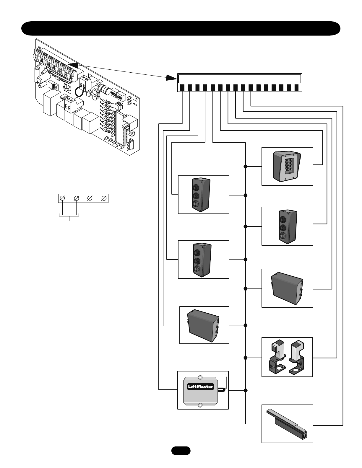
CONTROL CONNECTION DIAGRAMS
3
6
9
#
2
5
8
0
1
7
GL BOARD
24 Vac ACCESSORY POWER MAY BE FOUND ON
THESE TERMINALS
R1
R2
R3
R4
J1 TERMINAL BLOCK
12345678910111213141516
SOFT OPEN
INPUT (N.O.)
HARD CLOSE CONTROL
INPUT (N.O.)
OPEN
CLOSE
STOP
HARD OPEN
CONTROL INPUT (N.O.)
24 Vac
NOTE: See wiring diagrams shipped with kit for
additional information. See owner’s manual for wiring
distances and wire gauge information.
WARNING: All controls that are to be used to operate
the gate system, MUST be installed where the user
cannot come into contact with the gate while operating
the controls. Also, always install the controls where the
user has full view of gate operation.
* All inputs are normally open and momentary, except
the stop (N.C.). The following instructions are based
upon UL325, and include recommendations for
significant increase in safety.
* We strongly recommend that you follow the UL
guidelines presented throughout the manual.
Installation device instructions – always follow the
instructions provided by the manufacturer when
installing and adjusting any control device. If these
instructions are contrary to the advice given here,
call for assistance.
STOP/RESET
CONTROL INPUT (N.C.)
OPEN
CLOSE
STOP
SHADOW LOOP
INPUT (N.O.)
FREQ
RESIDENTIAL RADIO
(SINGLE BUTTON) INPUT (N.O.)
OPEN
CLOSE
STOP
INTERRUPT (SAFETY) LOOP
INPUT (N.O.)
FREQ
OBSTRUCTION OPEN
EDGE/PHOTO EYE INPUT (N.O.)
OBSTRUCTION CLOSE
EDGE/PHOTO EYE INPUT (N.O.)
34
Page 35

REPAIR PARTS - SW470
Refer to the parts lists below for replacement parts available for
your operator. If optional modifications and/or accessories are
included with your operator, certain components may be added or
removed from these lists. Individual components of each kit may
Complete Electrical Panel Replacement Kits
To order a complete electrical box replacement kit, add a
K- prefix to the model number of your operator. For example:
SW420-33-11 (Operator) = K73SW420-33-11 (Electrical Box Kit)
Motor Kits
To order a motor replacement kit, add a K prefix to the number of
your motor and remove the second dash (-). For example:
20-5752-33 (Motor Number) = K20-575233 (Motor Kit)
INDIVIDUAL PARTS
ITEM PART# DESCRIPTION
1 10-2013 Mounting Bracket
2 10-2103-T Reducer
Bracket
3 10-2104-T Motor Bracket
4 10-G0326 Switch Box Cover
5 10-G0387 Sensor Support Bracket
6 23-3001 On/Off Switch
7 K74-18382 Hall Effect Sensor Assembly
8 76-G0564 Alarm Assembly
9 10-18461 Side Cover
10 K001A5566 Control Board, GL
11 21-3260-1 Transformer, Dual Voltage 24V
12 G232016 Limit Switch
13 29-3530 Capacitor for 115V
29-12110 Capacitor for 230V
14 03-8024-K Mini Contactor 24V
not be available. Please consult a parts and service representative
regarding availability of individual components. Refer to page 40
for all repair part ordering information.
SERVICE KITS
ITEM PART# DESCRIPTION
K75-18364 Arm Assembly Kit
A1 10-2108-T Arm
Channel
A2 10-2109 Arm Extension
A3 10-2111 Gate Bracket
A4 07-2101 Arm Hub
A5 12-3000 Bearing 1-1/4" 1/8"
A6 07-2103 Arm Stop
A7 80-2103 Tinnerman Nut
K75-18365 Drive Assembly Kit
(Motor Not Included)
D1 11-2101 Shaft
D2 12-4164 Self Aligning
Flanged Mount Bearing
D3 G152142 Sprocket, 40B42 1x1/4"
D4 15-40B12-EEF Sprocket, 40B12 5/8"
D5 G162101 Belt 25"
D6 G176017 Pulley for Motor
D7 17-G0475 Molded Pulley 6"
D8 19-2153 Chain, #40-53 Pitches
D9 19-5040 Master Link, #40
D10 G202100 Motor, 115V, 1PH, 1/2HP
(Not Included in Kit)
20-2101-LD Motor 208/230V, 1PH, 1/2HP
(Not Included in Kit)
D11 G322100 Reducer 30:1
D12 75-G0089 Limit Collar Assembly
35
Page 36

ILLUSTRATED PARTS - SW470
A7
A2
A3
D8
D9
D3
1
D1
D12
D2
A1
A4
A6
6
4
2
D4
A5
9
1
8
D5
D11
10
3
5
7
D10
13
D6
D7
11
14
12
36
Page 37

REPAIR PARTS - SW490
Refer to the parts lists below for replacement parts available for
your operator. If optional modifications and/or accessories are
included with your operator, certain components may be added or
removed from these lists. Individual components of each kit may
not be available. Please consult a parts and service representative
regarding availability of individual components. Refer to page 40
for all repair part ordering information.
Complete Electrical Panel Replacement Kits
To order a complete electrical box replacement kit, add a
K- prefix to the model number of your operator. For example:
SW420-33-11 (Operator) = K73SW420-33-11 (Electrical Box Kit)
Motor Kits
To order a motor replacement kit, add a K prefix to the number of
your motor and remove the second dash (-). For example:
20-5752-33 (Motor Number) = K20-575233 (Motor Kit)
INDIVIDUAL PARTS
ITEM PART# DESCRIPTION
1 10-18458 Side Plate Cover
2 10-2013 Mounting Bracket
3 73-18457 Frame Assembly
4 10-G0326 Switch Box Cover
5 23-3001 On/Off Switch, 1PH
23-3005 On/Off Switch, 3PH
6 76-G0564 Alarm Assembly
7 K001A5566 Control Board, GL
8 12-2002 Bearing 1-1/2"x1-3/4"
SERVICE KITS
ITEM PART# DESCRIPTION
A1-7 K75-18366 Arm Assembly Kit
A1 08-2001 Rod End Fitting
A2 10-2011 Gate Bracket
A3 70-18618 Extension Arm
A4 10-3900 Galvanized Tube 39"
OD 1" IDx1.315"
A5 12-10172 Sleeve Bearing
A6 07-2103 Actuator Arm Stop
A7 06-2025-T Actuator Arm Assembly
K75-18367 Drive Assembly Kit
(Motor Not Included)
D1 10-2008 Switch Bracket
D2 10-G0539 Sensor Bracket
D3 Output Shaft*
D4 12-2125 Flange Ball Bearing 1-1/4" Bore
D5 G152002 Sprocket, 50B60
1-1/2x3/8 2-1/4" LTB
D6 15-50B12LGH Sprocket, 50B12 1/4KW
D7 16-4L280 Belt 28"
D8 17-2002 Pulley, 2", Bore 5/8", Key 3/16"
D9 G172701 Pulley, 7"
D10 19-2075 Chain, #50-75
D11 19-9024 Master Link, #50
D12 G232016 Limit Switch N.C. SPST
D13 32-2001 Gear Reducer
D14 75-G0400 Single Swing Collar
D15 75-G0401 Double Swing Collar
D16 K74-18382 Hall Effect Sensor Assembly
D17 80-1003 Tinnerman Nut
D18 31-2712 Nylon Spacer
D19 80-207-19 Key 1/4x1/4x1-1/2"
D20 80-207-23 Key 3/16x1-3/8"
D21 80-207-25 Key 3/8x3/8x2-1/4"
E1 03-8024-K Mini Contactor 24V
E2 21-3260-1 Transformer, Dual Voltage
E3 24-115-1 Relay 115 Vac
24-230-5 Relay, 208/230V
E4 25-2006 6 Amp Overload Fuse
25-2008 8 Amp Overload Fuse
25-2010 10 Amp Overload Fuse
25-2015 15 Amp Overload Fuse
25-2020 20 Amp Overload Fuse
25-4002-5 2.5 Amp Overload Fuse
25-4006 4.0-6.0 Amp Overload Fuse
F 20-1050-1T Motor, 115/230V TEFC, 1PH, 1/2HP
20-1075-1T Motor, 115/230V TEFC, 1PH, 3/4HP
20-1100-1T Motor, 115/230V TEFC, 1PH, 1HP
20-3050-1T Motor, 230/460V TEFC, 3PH, 1/2HP
20-3075B-4T Motor, 230/460V TEFC, 3PH, 3/4HP
20-3100B-4T Motor, 230/460V TEFC, 3PH, 1HP
20-3050B-5T Motor, 575V TEFC, 3PH, 1/2HP
20-3100M-5T Motor, 575V TEFC, 3PH, 3/4HP
20-3100-5T Motor, 575V TEFC, 3PH, 1HP
37
Page 38

ILLUSTRATED PARTS - SW490
A5
A1
A4
D12
D12
D1
D17
D5
D20
D18
D21
D4
D10
D19
A3
D11
D3
A7
6
3
D14
D15
D6
5
4
A5
A2
8
1
A6
2
D7
D13
D16
D2
E5
E3
7
E4
D9
F
E1
E2
D8
38
Page 39

VARIABLE PARTS - SW490
VARIABLE PARTS LIST - SW490
PART PART NO. DESCRIPTION USED ON
20-1050-1T 1PH 1/2HP Base Mnt. 115/230V TEFC SW490-33-11, SW490-33-21, SW490-50-11,
SW490-50-21
20-1075-1T 1PH 3/4HP Base Mnt. 115/230V TEFC SW490-75-11, SW490-75-21
20-XXXX 20-1100B-2T 1PH 1HP Base Mnt. 115/230V TEFC SW490-100-11, SW490-100-21
(Motor) 20-3050-1T 3PH 1/2HP Base Mnt. 230/460V TEFC SW490-33-23, SW490-33-43, SW490-50-23,
SW490-50-43
20-3075B-4T 3PH 3/4HP Base Mnt. 230/460V TEFC SW490-75-23, SW490-75-43
20-3100B-4T 3PH 1HP Base Mnt. 230/460V TEFC SW490-100-23, SW490-100-43
23-XXXX 23-3001 On/Off SW, 1PH All 1PH
(Switch) 23-3005 On/Off SW, 3PH All 3PH
24-XXX-X 24-115-1 TPDT, 115V Coil (IR) All 115V 1PH
(Relay) 24-230-5 TPDT, 230V Coil (IR) All 230V 1PH
25-2006 6 Amp SW490-33-21, SW490-50-21, SW490-75-21
25-20XX 25-2008 8 Amp SW490-33-11
(Overload) 25-2010 10 Amp SW490-50-11, SW490-100-21
25-2015 15 Amp SW490-75-11
25-2020 20 Amp SW490-100-11
25-40XX 25-4001-8K 1.2 to 1.8 Amp SW490-100-53-G, SW490-75-53-G
(Overload) 25-4002-5K 1.6 to 2.5 Amp SW490-100-43-G
25-4004-K 3.3 to 5.5 Amp SW490-100-23-G, SW490-100-83-G
SAFETY ACCESSORIES FOR SECONDARY ENTRAPMENT PROTECTION
The following devices are acceptable for Safety Accessories for
secondary entrapment protection.
PHOTO-ELECTRIC CONTROLS
MODEL DESCRIPTION VOLTAGE
AOMRON Photocell/Electric Eye - 30' (9 m) Maximum Range +24V ac/dc
MODEL DESCRIPTION
G65MG0204 Miller MG020 2-wire electric edge for gates. Sensitized on three sides.
Requires mounting channel (4' [1.2 m] long).
G65MG0205 Miller MG020 2-wire electric edge for gates. Sensitized on three sides.
Requires mounting channel (5' [1.5 m] long).
G65ME12C5 Mounting Channel - 5' (1.5 m) long
G65MGR205 Miller MGR20 2-wire electric edge in 5' (1.5 m) lengths for 2" (5 cm) round post.
G65MGS205 Miller MGR20 2-wire electric edge in 5' (1.5 m) lengths for 2" (5 cm) square post.
SENSING EDGES
39
Page 40

WARRANTY POLICY AND SERVICE
LIFTMASTER® TWO YEAR LIMITED WARRANTY
The Chamberlain Group, Inc. warrants to the final purchaser of this product, for the structure in which this product is originally
installed, that it is free from defect in materials and/or workmanship for a period of two years from the date of purchase. The proper
operation of this product is dependent on your compliance with the instructions regarding installation, operation, maintenance and
testing. Failure to comply strictly with those instructions will void this limited warranty in its entirety.
If, during the limited warranty period, this product appears to contain a defect covered by this limited warranty, call 1-800-528-2806,
toll free, before dismantling this product. Then send this product, pre-paid and insured, to our service center for warranty repair. You
will be advised of shipping instructions when you call. Please include a brief description of the problem and a dated proof-of-purchase
receipt with any product returned for warranty repair. Products returned to Seller for warranty repair, which upon receipt by Seller are
confirmed to be defective and covered by this limited warranty, will be repaired or replaced (at Seller’s sole option) at no cost to you
and returned pre-paid. Defective parts will be repaired or replaced with new or factory-rebuilt parts at Seller’s sole option.
ALL IMPLIED WARRANTIES FOR THE PRODUCT, INCLUDING BUT NOT LIMITED TO ANY IMPLIED WARRANTIES OF
MERCHANTABILITY AND FITNESS FOR A PARTICULAR PURPOSE, ARE LIMITED IN DURATION TO THE TWO YEAR LIMITED
WARRANTY PERIOD SET FORTH ABOVE, AND NO IMPLIED WARRANTIES WILL EXIST OR APPLY AFTER SUCH PERIOD. Some
States do not allow limitations on how long an implied warranty lasts, so the above limitation may not apply to you. THIS LIMITED
WARRANTY DOES NOT COVER NON-DEFECT DAMAGE, DAMAGE CAUSED BY IMPROPER INSTALLATION, OPERATION OR CARE
(INCLUDING, BUT NOT LIMITED TO ABUSE, MISUSE, FAILURE TO PROVIDE REASONABLE AND NECESSARY MAINTENANCE,
UNAUTHORIZED REPAIRS OR ANY ALTERATIONS TO THIS PRODUCT), LABOR CHARGES FOR REINSTALLING A REPAIRED OR
REPLACED UNIT, OR REPLACEMENT OF BATTERIES.
THIS LIMITED WARRANTY DOES NOT COVER ANY PROBLEMS WITH, OR RELATING TO, THE GATE OR GATE HARDWARE,
INCLUDING BUT NOT LIMITED TO THE GATE ALIGNMENT OR HINGES. THIS LIMITED WARRANTY ALSO DOES NOT COVER ANY
PROBLEMS CAUSED BY INTERFERENCE. ANY SERVICE CALL THAT DETERMINES THE PROBLEM HAS BEEN CAUSED BY ANY OF
THESE ITEMS COULD RESULT IN A FEE TO YOU.
UNDER NO CIRCUMSTANCES SHALL SELLER BE LIABLE FOR CONSEQUENTIAL, INCIDENTAL OR SPECIAL DAMAGES ARISING IN
CONNECTION WITH USE, OR INABILITY TO USE, THIS PRODUCT. IN NO EVENT SHALL SELLER’S LIABILITY FOR BREACH OF
WARRANTY, BREACH OF CONTRACT, NEGLIGENCE OR STRICT LIABILITY EXCEED THE COST OF THE PRODUCT COVERED HEREBY.
NO PERSON IS AUTHORIZED TO ASSUME FOR US ANY OTHER LIABILITY IN CONNECTION WITH THE SALE OF THIS PRODUCT.
Some states do not allow the exclusion or limitation of consequential, incidental or special damages, so the above limitation or
exclusion may not apply to you. This limited warranty gives you specific legal rights, and you may also have other rights which vary
from state to state.
HOW TO ORDER REPAIR PARTS
OUR LARGE SERVICE ORGANIZATION
SPANS AMERICA
FOR INSTALLATION AND SERVICE INFORMATION,
CALL OUR TOLL FREE NUMBER
1-800-528-2806
www.liftmaster.com
WHEN ORDERING REPAIR PARTS
PLEASE SUPPLY THE FOLLOWING INFORMATION:
PART NUMBER DESCRIPTION MODEL NUMBER
ADDRESS ORDER TO:
THE CHAMBERLAIN GROUP, INC.
Technical Support Group
6020 Country Club Road
Tucson, AZ 85706
© 2010, The Chamberlain Group, Inc.
01-18452H All Rights Reserved
 Loading...