

Page 1
Garage Opener
• Please read this manual and the enclosed safety materials carefully!
• Fasten the manual near the garage door after installation.
• The door WILL NOT CLOSE unless the Protector System® is connected
and properly aligned.
• Periodic checks of the garage door opener are required to ensure
safe operation.
Owner’s Manual
B500 • B503 • B510
Belt Drive
Garage Door Opener
FOR RESIDENTIAL USE ONLY
PRE-PROGRAMMED REMOTE CONTROL
INCLUDED
TO WATCH VIDEOS GO TO:
tinyurl.com/lgh5x3h
• The model number label is located on the left side panel of your
garage door opener.
• This garage door opener is compatible with MyQ® and
Security+2.0® accessories.
• DO NOT install on a one-piece door if using devices or features
providing unattended close. Unattended devices and features are
to be used ONLY with sectional doors.
Contents
Preparation ......................................2-5
Assembly ....................................... 6-10
Installation .................................. 11-28
Install the Door Control ............ 21-22
Install the Protector System® .... 23-26
Power ......................................27-28
Adjustments .................................29-31
Operation ..........................................32
Features .......................................33
Using your Garage Door Opener .....34
Multi-Function Control Panel .... 34-35
Remote Control and
Keyless Entry ........................... 35-36
Homelink® ...................................36
To Erase the Memory .....................36
To Open the Door Manually ...........37
Maintenance .....................................38
Troubleshooting ........................... 39-40
Accessories ........................................41
Warranty ...........................................42
Repair Parts .................................43-44
www.chamberlain.com
www.mychamberlain.com
Page 2
Torsion
Spring
Extension
Spring
OR
Preparation
Safety Symbol and Signal Word Review
This garage door opener has been designed and tested to offer safe service provided it is installed, operated,
maintained and tested in strict accordance with the instructions and warnings contained in this manual.
Whenyou see these Safety Symbols and Signal Words on
the following pages, they wi ll alert you to the possibil ity of
Mechanical
serious injury or death i f you do not comply wi th the
warnings that accompany them.The hazard may come
from something mechanical or from electric shock. Read
Electrical
the warnings carefully.
Whenyou see this Signal Word on the followi ng pages, it
will alert you to the possibility of damage to your garage
door and/or the garage door opener if you do not comply
with the cautionary statements that accompany it. Read
themcarefully.
WARN ING: This product can expose you to chemicals i ncluding lead, which are known to the State of
California to causecancer or birth defects or other reproductive harm. For more information go to
www.P65Warnings.ca.gov
Unattended Operation
The Timer-to-Cl ose (TTC) feature, the MyQ®Smartphone Control app, and MyQ®Garage Door and Gate Monitor
are examples of unattended close and are to be used ON LY with sectional doors. Any device or feature that allows the
door to close without being in the li ne of si ght of the door is consideredunattended close. The T imer-to-Close (TTC)
feature, the MyQ®Smartphone Control, and any other MyQ®devices are to be used ONLY with sectional doors.
Check the Door
To prevent possible SERIOUSINJURYor DEATH :
l ALWAYScall a trained door systems technician if garage door binds, sticks, or is out of balance. An
unbalanced garage door may NOT reverse when r equired.
l NEVER try to loosen, move or adjust garage door, door springs, cables, pulleys, brackets or their hardware,
ALLof w hich are under EXTR EME tension.
l Disable ALLlocks and r emoveALLropes connected to garage door BEFORE installation and operating
garage door opener to avoid entanglement.
l DO NOT install on a one-piece door if using devices or features providing unattended close. Unattended
devices and features are to be used ONLY with sectional doors.
To prevent damage to garage door and opener:
l ALWAYSdisable locks BEFORE installing and operating the opener.
l ONLY operate garage door opener at 120V, 60Hz to avoid malfunction and damage.
Before you begin:
1. Disable locks and remove any r opes connectedto the garage door.
2. Lift the door halfway up. R elease the door. If balanced, it should stay in place,
supportedentirely by its springs.
3. Raise and lower the door to check for binding or sticki ng. If your door binds,
sticks, or is out of balance, call a traineddoor systems technician.
4. Check the seal on the bottomof the door. Any gap between the floor and the
bottom of the door must not exceed 1/4 inch (6 mm). Otherwise, the safety
reversal system may not work properly.
5. The opener should be installed above the center of the door. If there is a torsion
spring or center bearing plate in the way of the header bracket, it may be
installed w ithin 4feet (1.2m) to the left or right of the door center. See page 12.
2
Page 3
3/16
7/16
1/2
5/32
5/16
5/8
9/16
1/4
7/16
Preparation
Additional Items You May Need:
Survey your garage area to see if you w ill needany of the following items:
n (2) 2X4 PIECES OF WOOD
May be used to fasten the header bracket to the structural supports. Also used to position the garage door
opener during installation and for testing the safety reversi ng sensors.
n SUPPORT BR ACKET AND FASTENIN G H ARDWARE
Must be used if you have a finished ceiling in your garage.
n EXTENSION BRACK ETS (MODEL 041A5281-1) OR WOOD B LOCKS
Dependingupon garage construction, extension brackets or wood blocks may be neededto install the
safety reversing sensor.
n FASTENIN G H ARDWARE
Alternate floor mounting of the safety r eversing sensor will require hardware not provided.
n DOOR REINFORC EMENT
Required if you have a lightweight steel, aluminum,fiberglass or glass panel door.
n RAIL EXTENSION K IT
Required if your garage door is more than 7 feet (2.13m) high.
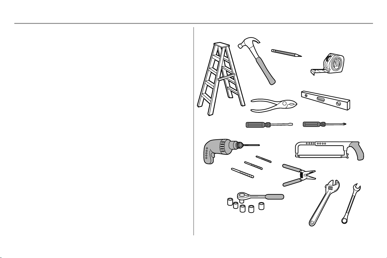
Tools Needed
3
Page 4
OR
P
Preparation
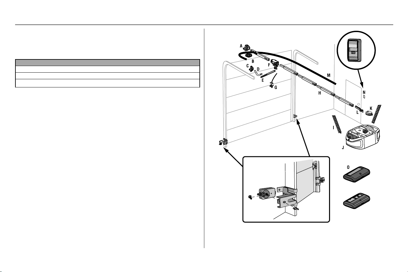
Carton Inventory
Save the cartonand packing material until the installation and adjustment is complete. Instructions for the accessories
will be attachedto the accessory andare not i ncluded in this manual. The images throughout this manual are for
reference only and your product may look different.
Model Power Doo r C ont rol Remot e Control Wireless Keypad
B500 Med Lift Power System™ Multi-Function 1-button(2)
B503 Med Lift Power System™ Multi-Function 3-button(2)
B510 Med Lift Power System™ Multi-Function 3-button(2)
A. Header bracket
B. Pulley
C. D oor bracket
D. C urved door arm
E. Straight door arm (Packaged inside front rail section)
F. T rolley
NOTE: Be sure to assemble the trolley before sliding onto rail.
G. Emergency r elease rope and handle
H. R ail (1 front and 4 center sections)
I. Hanging brackets (2) ( Packagedinside the fr ont rail section)
J. Garagedoor opener (motor unit)
K. Sprocket cover and scr ews
L. “U ” bracket
M. Belt
N. D oor control
O. Remote control
P. The Prot ector System
Safety reversi ng sensors wi th 2 conductor white and white/black wire attached: Sending Sensor (1),
Receiving Sensor (1), and Safety Sensor Brackets (2)
NOT SH OWN
Wireless Keypad
White and red/white wire
Owner's manual
Hardware
®
ü
4
Page 5
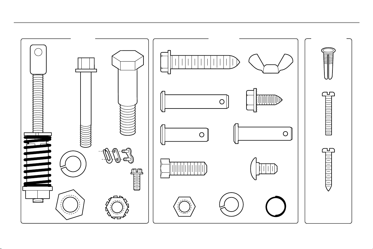
ASSEMBLY INSTALLATION
DOOR CONTROL
Insulated Staples
(Not
Shown)
Clevis Pin 5/16"x1-1/2"
Ring
Fastener (3)
Hex Bolt 5/16"-18x7/8" (4)
Self-Threading Screw
1/4"-14x5/8" (2)
Clevis Pin 5/16"x1" Clevis Pin 5/16"x1-1/4"
Carriage Bolt
1/4"-20x1/2" (2)
Wing Nut
1/4"-20 (2)
Lag Screw 5/16"-9x1-5/8" (4)
Screw 6ABx1" (2)
Drywall Anchors (2)
Screw 6-32x1" (2)
Hex Screw #8x3/8" (2)
(packed with the
sprocket cover)
Bolt
1/4"-20x1-3/4"
Lock Nut
1/4"-20
Bolt
Nut 3/8"
Lock Washer 3/8"
Master Link
Threaded
Shaft with
Spring
Trolley Nut
Lock Washer
5/16"-18 (4)
Nut
5/16"-18 (4)
Preparation
Hardware
5
Page 6
Assembly
Wear Pads
Front Rail Section
(TO DOOR)
“U” Bracket
(TO MOTOR UNIT)
Trolley
Rail Tab
On Top
Slide to stops
on top and sides
of “U” bracket
Screwdriver
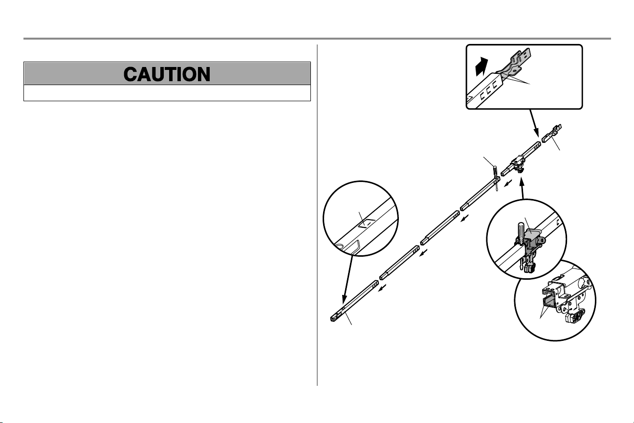
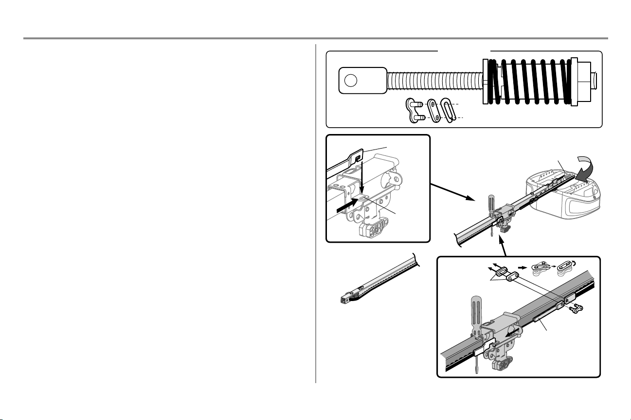
STEP 1 Assemble the rail and install the trolley
To prevent INJURY from pinching, keephands and fingers away from the joints while assembling the r ail.
To avoid installation difficulties, do not run t he garage d oor op ener until instructed t o do so.
The front rail has a cut out “w indow” at the door end. The rail tab MUST be on top of the r ail when assembled.
1. Remove the straight door arm and hangingbracket packaged inside the front r ail and set aside for
Installation Step 5 and 9. NOTE: To prevent INJURY w hile unpacking the rail carefully remove the straight
door arm stored w ithin the rail section.
2. Align the rail sections on a flat surface as shown and slide the tapered ends intothe larger ones. Tabs
along the side will lock into place.
3. Place the motor unit on packing material to protect the cover, and rest the back end of the rail on top. For
convenience, put a support under the frontend of the rail.
4. As a temporary stop, insert a screwdriver into the hole in the second r ail section fr om the motor unit, as
shown.
5. Check to be sure there are 4 plastic w ear pads inside the inner trolley. If they became loose during
shipping, check all packing material. Snap them back into position as shown.
6. Slide the trolley assembly toward the screwdriver as shown.
7. Slide the rail onto the “U” bracket, until it reaches all the stops on the top and sides of the “U ” bracket.
6
Page 7
Assembly
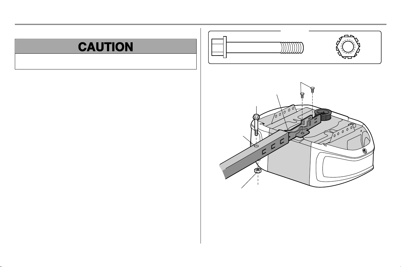
Bolt
1/4"-20x1-3/4"
Lock Nut
1/4"-20
HARDWARE
“U” Bracket
Cover Protection
Bolt Hole
Bolt
Lock Nut
Bolts (Mounted in the
garage door opener)
STEP 2 Fasten the rail to the motor unit
To avoid SERIOU S damageto garage door opener, use ONLY those bolts/fasteners mounted in the top of the
opener.
1. Insert a 1/4"-20 x 1-3/4" bolt into the cover protection bolt hole on the back end of the rail as shown. Tighten
securely with a 1/4"-20 lock nut. D O NOT overtighten.
2. Remove the bolts from the top of the motor unit.
3. Use the carton to support the front end of the rail .
4. Place the “U ” bracket, flat side down onto the motor unit and align the bracket holes w ith the bolt holes.
5. Fasten the “ U” bracket with the previously removed bolts; D O N OT use any power tools. The use of power
tools may permanently damage the garage door opener.
7
Page 8
Assembly
Rail
Idler Pulley
Grease Inside
Pulley
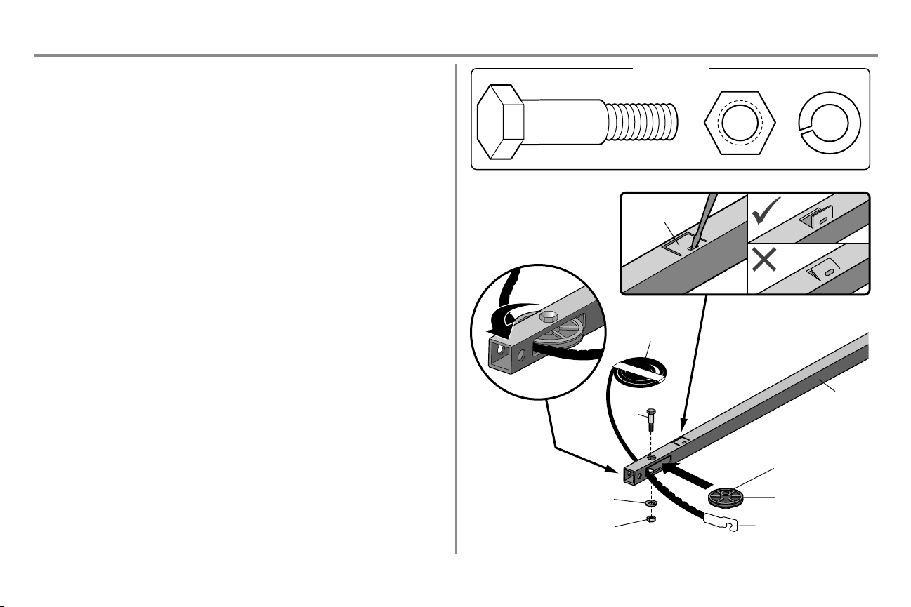
Bolt
Belt
Lock Washer
Nut
Bolt
Nut 3/8" Lock Washer 3/8"
HARDWARE
Trolley Connector
Rail Tab
STEP 3 Install the idler pulley
1. Lay the belt beside the rail, as shown. Grasp the end with the hooked trolley connector and pass
approximately 12" (30 cm) of belt through the w indow. Keep the r ibbed side toward the rail, and allow it to
hanguntil Assembly Step 4.
2. Remove the tape from the idler pulley. The inside center should be pre-greased. If dry, regrease to ensure
proper operation.
3. Place the idler pulley intothe window as shown.
4. Insert the idler bolt from the top through the rail and pulley. Tightenwith a 3/8" lock washer and nut
underneath the rail until the lock washer is compressed.
5. Rotate the pulley to be sure it spins freely.
6. Locate the rail tab. The rail tab is between the idler bolt and the trolley in the front rail section. Use a
flathead screwdriver and lift the rail tab until the tab is vertical (90º).
8
Page 9
Assembly
HARDWARE
Master Link
Figure 3
Threaded Shaft with Spring Trolley Nut
Threaded Shaft
Master Link
Sprocket
Figure 2
Figure 1
Trolley
Connector
Retaining
Slot
STEP 4 Install the belt
1. Pull the belt around the idler pulley and toward the trolley. The ribbed si de must contact the pulley.
2. Hook the troll ey connector into the retaining sl ot on the tr olley as shown ( Figure 1).
3. With the trolley against the screwdriver, dispense the remainder of the belt along the rail lengthtoward the
motor unit and around the sprocket (Figure 2). The sprocket teeth must engage the belt.
4. Check to make sure the belt i s not twisted.Connect the trolley threaded shaft wi th the master link(Figure
3).
l Push pins of master link bar through holes i n end of belt and trolley threaded shaft.
l Push master link cap over pins and past pin notches.
l Slide the closed end of the clip-on spring over one of the pins. Push the open end of the clip-on spring
ontothe other pin.
5. Remove the spring trolley nut from the threaded shaft.
6. Insert the trolley threaded shaft through the hole in the troll ey.
9
Page 10
Assembly
Spring
Trolley Nut
Nut Ring Slot
Nut RingNut Ring
AFTER
1-1/4" (3.18 cm)
BEFORE
1" (2.5 cm)
Hex Screw #8x3/8"
(Packed with the sprocket cover)
HARDWARE
Hex Screw #8x3/8"
Sprocket Cover
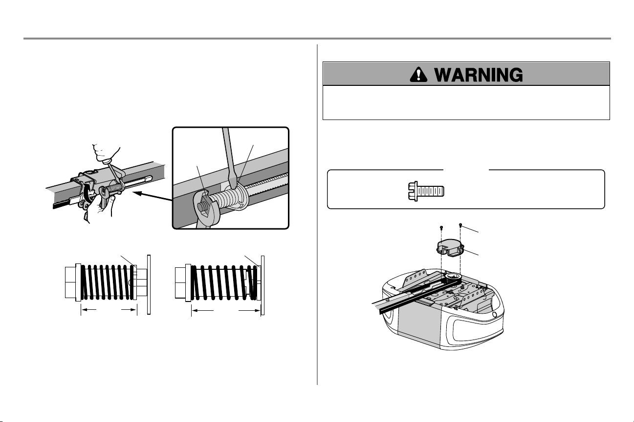
STEP 5 Tighten the belt
1. By hand, thread the spring trolley nut on the threadedshaft until i t is finger tight against the trolley. Do not
use any tools. Remove the screwdriver.
2. Insert a flathead screwdriver tip into one of the nut r ing slots and brace it firmly against the trolley.
3. Tighten the spring trolley nut w ith an adjustable wrench or a 7/16" openendwrench about a quarter turn
until the spring releases and snaps the nut ring against the troll ey. This sets the spring to optimum belt
tension.
STEP 6 Install the sprocket cover
To avoid possible SERIOUS INJURY to finger fr om moving garage door opener:
l ALWAYSkeep handclear of sprocket while operating opener.
l Securely attach sprocket cover BEFORE operating.
1. Position the sprocket cover over the sprocket as shown and fasten to the mountingplate with 8x3/8" hex
screws provided.
You have n ow finished assembling your garage doo r o pener. Please read the following warnings before
proceeding t o the installation section.
10
Page 11
Installation
Change 5. to say "Where possible, i nstall the door opener 7 feet (2.13 m) or more above the floor." per regulatory Bill Carrey.
IMPORTANT INSTALLATION INSTRUCTIONS
To reduce the risk of SEVERE INJURY or DEATH:
1. READ AND FOLLOW ALL INSTALLATION WARN INGS AND INSTRUCTIONS.
2. Install garage door opener ON LY on properly balanced and lubricated garage door. An improperly balanced
door may N OT reverse whenrequired and could result in SEVERE INJU RY or DEATH.
3. ALL repairs to cables, spring assemblies and other hardware MUST be made by a tr ained door systems
technician BEFORE installing opener.
4. Disable ALL locks and r emoveALL ropes connected to garage door BEFORE installing opener to avoid
entanglement.
5. Where possible, install the door opener 7 feet (2.13 m) or more above the floor.
6. Mountthe emergency release w ithin reach, but at least 6 feet (1.83m) above the floor and avoiding contact
with vehicles to avoid accidental r elease.
7. NEVER connect garage door opener to power source until instructed to do so.
8. NEVER w ear w atches, rings or loose clothing while installing or servicing opener. They could be caughtin
garage door or opener mechanisms.
Step 11. changed" manual" to "emergency" label. Per Bill C. regulatory. Updated in 114A5010MDR. Updated in
114A4862,114A5051. - LTB
9. Install wall-mounted garage door control:
l within sight of the garage door.
l out of reach of small children at a minimum height of 5feet (1.5m) above floors, landings, steps or any
other adjacent walking surface.
l away from ALL moving parts of the door.
10. Place entrapmentwarning l abel on wall next to garage door control.
11. Place emergency r elease/safety r everse test label in plain view on inside of garage door.
12. Upon completion of installation, test safety reversal system. Door MUST reverse on contact with a 1-1/2"
(3.8cm) high object (or a 2x4 laid flat) on the floor.
13. To avoid SERIOU S PERSONAL INJURY or DEATH from electrocution, disconnect ALL electric power
BEFORE performing ANY service or maintenance.
14. DO NOT install on a one-piece door if using devices or features providing unattendedclose. U nattended
devices and features are to be used ONLY with sectional doors.
11
Page 12
Installation
Header Wall
Vertical Centerline of Garage Door
2x4
Structural
Supports
Level
(Optional)
Unfinished
Ceiling
2x4
OPTIONAL CEILING MOUNT
FOR HEADER BRACKET
Sectional door with curved track
Header Wall
Track
2" (5 cm)
Highest
Point of
Travel
Door
One-piece door with horizontal track
Header Wall
Track
2" (5 cm)
Highest
Point of
Travel
Door
One-piece door without track:
jamb hardware
Header Wall
8" (20 cm)
Highest
Point of
Travel
Door
Jamb
Hardware
One-piece door without track:
pivot hardware
Header Wall
8" (20 cm)
Highest
Point of
Travel
Door
Pivot
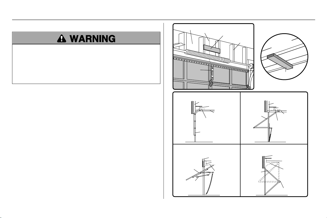
STEP 1 Determine the header bracket location
To prevent possible SERIOUS IN JUR Y or D EATH:
l Header bracket MUST be R IGIDLY fastened to str uctural support on header wall or ceiling, otherwise
garage door might NOT reverse whenrequired. DO NOT install header bracket over dryw all.
l Concrete anchors MUST be used if mountingheader bracket or 2x4 into masonry.
l NEVER try to loosen, move or adjust garage door, springs, cables, pulleys, brackets, or their hardware, ALL
of which are under EXTR EME tension.
l ALWAYScall a trained door systems technician if garage door binds, sticks, or is out of balance. An
unbalanced garage door might N OT reverse whenrequired.
Installation procedures vary according to garage door types. Follow the instructions which apply to your door.
1. Close the door and mark the inside vertical centerline of the garage door.
2. Extend the line onto the header wall above the door.Youcan fasten the header bracket within 4 feet ( 1.22 m)
of the left or right of the door center only if a torsion spring or center bearing plate is i n the w ay; or you can
attach it to the ceil ing (see page 13) w hen clearance is minimal. (It may be mounted on the w all upside
down if necessary, to gain approximately 1/2" (1 cm). If you needto install the header bracket on a 2x4 ( on
wall or ceiling), use lag screws (not provided) to securely fasten the 2x4 to structural supports as shown
here and on page 13.
3. Open your door to the highest point of travel as shown. Dr aw an intersecting horizontal line on the header
l 2" ( 5 cm) above the high point for sectional door and one-piece door w ith track.
l 8" ( 20 cm) above the high point for one-piece door without track.
This height will provide travel clearance for the top edge of the door. NOTE: If the total number of inches exceeds the
height available in your garage, use the maximumheight possible, or refer to page13 for ceiling installation.
wall 2" ( 5 cm) above the high point:
12
Page 13
Installation
Lag Screw 5/16"-9x1-5/8"
HARDWARE
UP
Wall Mounting
Holes
WALL INSTALLATION
CEILING INSTALLATION
Optional Mounting
Holes
Vertical
Centerline of
Garage Door
Header Wall
Header
Bracket
2x4
Structural
Support
Door
Spring
Garage Door
Highest Point
of Garage
Door Travel
Horizontal
Line
Lag
Screw
UP
Header Wall
Ceiling Mounting
Holes
Finished Ceiling
Vertical
Centerline of
Garage Door
Header
Bracket
6" (15 cm)
Maximum
Door Spring
Garage Door
Lag Screw
STEP 2 Install the header bracket
You can attach the header bracket either to the w all above the garage door, or to the ceiling. Follow the instructions
which wi ll work best for your particular r equirements. D o not install t he header bracket over drywall. If installing
into masonry, use concrete anchors (not pro vided).
OPTION A - WALL INSTALLATION
1. Center the bracket on the vertical centerline w ith the bottom edge of the bracket on the horizontal line as
shown ( with the arrow pointing toward the ceiling).
2. Mark the vertical set of bracket holes. D ril l 3/16" pilot holes and fasten the bracket securely to a structural
OPTION B - CEILING INSTALLATION
1. Extend the vertical centerline onto the ceiling as shown.
2. Center the bracket on the vertical mark, no more than 6" (15 cm) from the wall. Make sure the arr ow is
3. Mark the side holes. D rill 3/16" pilot holes and fasten bracket securely to a structural support wi th the
support with the hardware provided.
pointing away from the w all. The bracket can be mounted flush against the ceili ng when clearance is
minimal.
hardware provided.
13
Page 14
Installation
HARDWARE
Clevis Pin
5/16"x1-1/2"
Ring Fastener
Clevis Pin
Ring Fastener
Connected Disconnected
One-piece door
without tracks
2x4 2x4
All other
door types
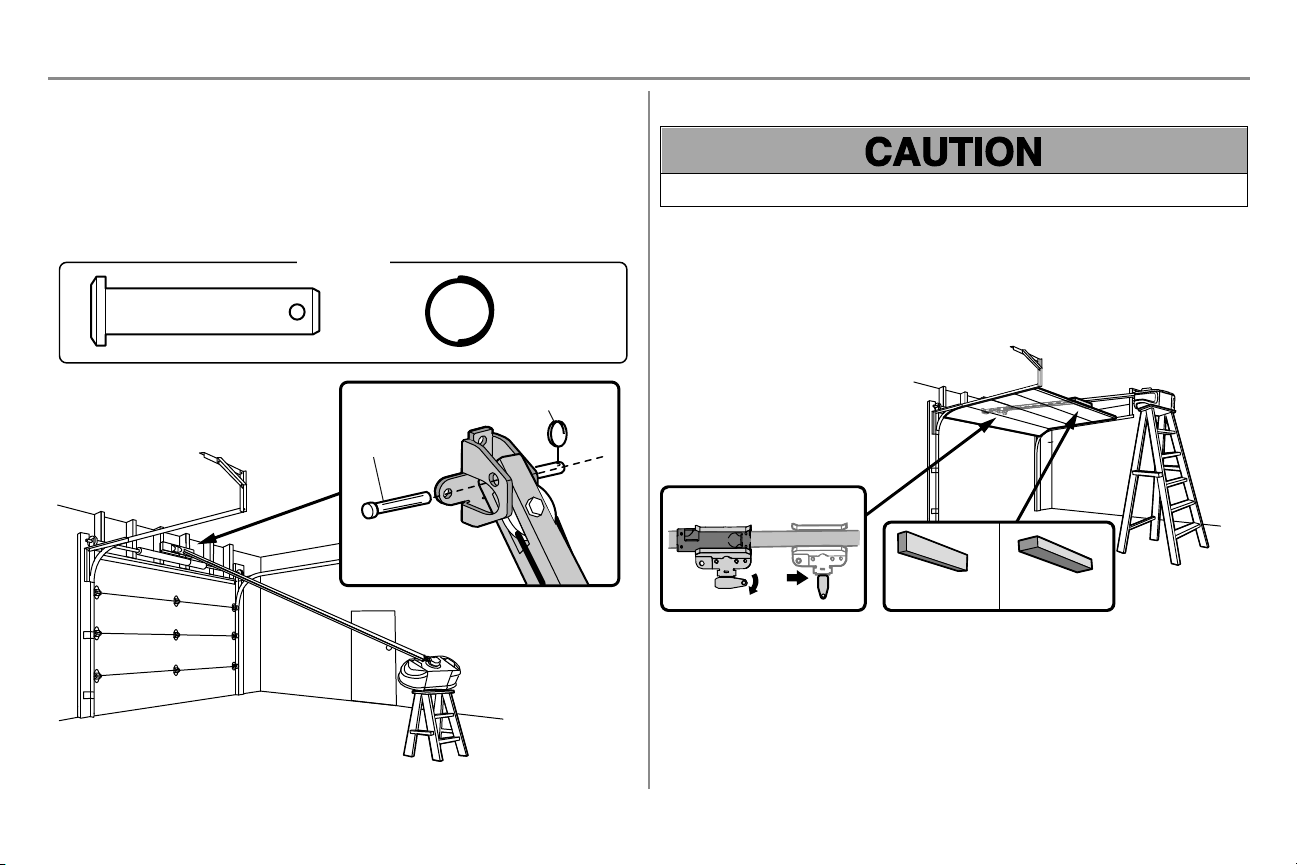
STEP 3 Attach the rail to the header bracket
1. Position the opener on the garage floor below the header bracket. Use packing material as a protective
base.
NOTE: If the door spring is in the w ay, you will need help. Have someone hold the opener securely on a
temporary support to allow the rail to clear the spring.
2. Position the rail bracket against the header bracket.
3. Align the bracket holes and join with a clevis pin as shown.
4. Insert a ring fastener to secure.
STEP 4 Position the garage door opener
To prevent damage to garage door, rest garage door opener r ail on 2x4 placed on top section of door.
1. Remove the packing material and l ift the garage door opener onto a ladder.
2. Fully open the door and place a 2x4 (laid flat) under the r ail. For one-piece doors w ithout tracks, lay the
2x4 on it's side.
NOTE: A 2x4 is ideal for setting the distancebetweenthe rail and the door. If the ladder is not tall enough you will
needhelp at this point. If the door hits the trolley whenit is r aised, pull the trolley r elease arm down to disconnect the
inner and outer trolley. Slide the outer trolley toward the garage door opener. The tr olley can remain disconnected
until instructed.
14
Page 15
Installation
Finished Ceiling
Lag Screw
1
2
3
Not
Provided
Not Provided
Not Provided
Hex Bolt
Nut
Lock
Washer
4 5
6
Lag Screw
Finished Ceiling
EXAMPLES
Unfinished Ceiling
HARDWARE
Hex Bolt
5/16"- 18x7/8"
Nut
5/16"-18
Lock Washer
5/16"-18
Lag Screw
5/16"-9x1-5/8"
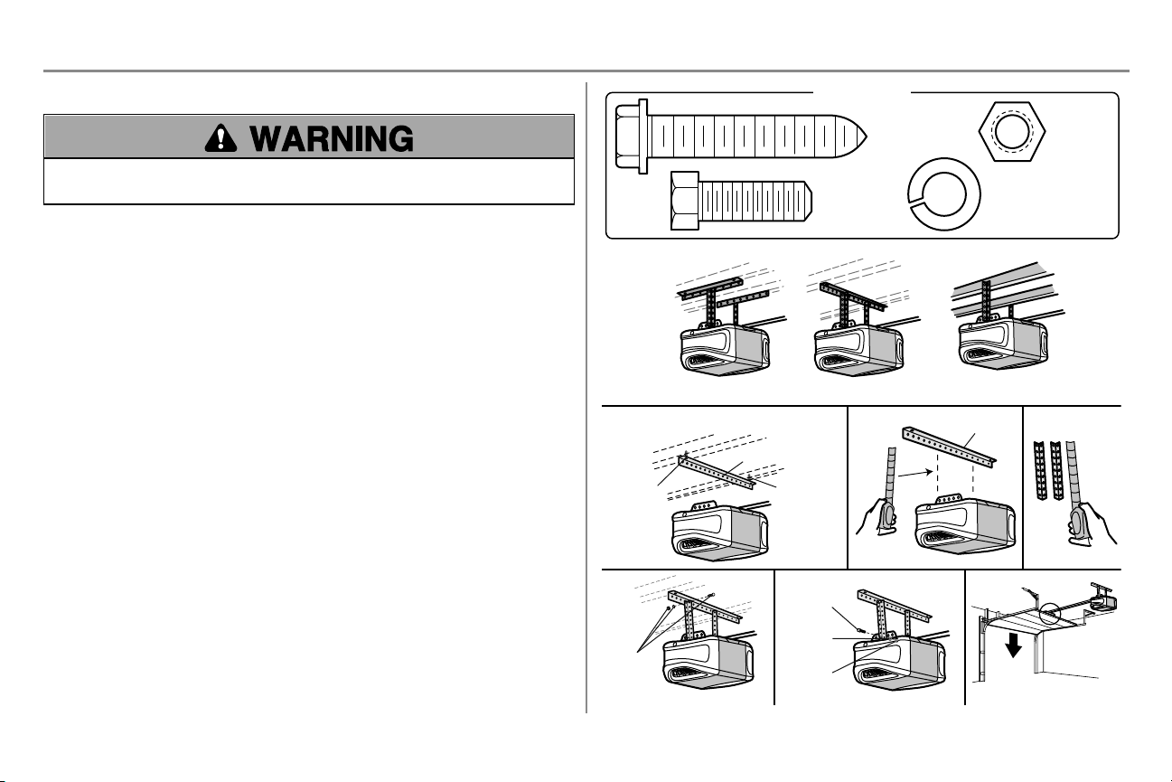
STEP 5 Hang the garage door opener
To avoid possible SERIOUS INJURY from a falling garage door opener, fasten it SECU RELY to structural
supports of the garage. Concrete anchors MUST be used if installi ng ANY brackets into masonry.
Hanging the garage door opener will vary dependingon your garage. Below are three example installations. Your
installation may be different. For ALL installations the garage door opener MUST be connectedto structural supports.
The instructions il lustrate one of the examples below.
1. On finished ceilings, use the lag screws to attach a support bracket (not provided) to the structural
supports before installing the garage door opener.
2. Make sure the garage door opener is aligned w ith the header bracket. Measure the distance from each side
of the garage door opener to the support bracket.
3. Cut both pieces of the hanging bracket to required lengths.
4. Attach the end of each hanging bracket to the support bracket with appropriate hardware (not provided).
5. Attach the garage door opener to the hanging brackets wi th the hex bolts, lock washers, and nuts.
6. Remove the 2x4 and manually close the door. If the door hits the rail, raise the header bracket.
15
Page 16

Installation
or
or
STEP 6 Install the Light Bulbs
To prevent possible OVERHEATING of the end panel or light socket:
l Use ONLY A19 incandescent (100W maximum) or compact fluorescent (26W maximum) light bulbs.
l DO NOT use incandescent bulbs larger than 100W.
l DO NOT use compact fluorescent light bulbs l arger than 26W (100W equivalent).
l DO NOT use halogen bulbs.
l DO NOT use short neck or specialty light bulbs.
1. Pull on the top sides of the l ight lens and rotate the light lens down.
2. Insert an A19 incandescent (100W maximum) or compact fluorescent (26W, 100W equivalent) light bulb
into the light socket.
3. Rotate the lens up to close.
NOTE: Do not use halogen, short neck, or specialty light bulbs as these may overheat the end panel or light socket.
Do not use LED bulbs as they may reduce the rangeor performance of your remote controls.
STEP 7 Attach the emergency release rope and handle
To prevent possible SERIOUS IN JUR Y or D EATH froma falling garage door:
l If possible, use emergency r elease handle to disengage trolley ONLY when garage door is C LOSED. Weak
or broken springs or unbalanceddoor could result in an open door falling rapidly and/or unexpectedly.
l NEVER use emergency release handle unless garage doorway is clear of persons and obstructions.
l NEVER use handle to pull door open or closed. If rope knot becomes untied, you could fall.
1. Insert one end of the emergency r elease rope through the handle. Make sure that “N OTICE” is ri ght side
up. Secure w ith an overhand knot at l east 1" (2.5 cm) from the end of the r ope to prevent slipping.
2. Insert the other end of the emergency release rope through the hole in the trolley release arm. Mount the
emergency release w ithin reach, but at least 6 feet (1.83m) above floor, avoiding contact w ith vehicles to
prevent accidental release and secure with an overhand knot.
NOTE: If it is necessary to cut the emergency release rope, seal the cut end wi th a match or lighter to prevent
unraveling. Ensure the emergency release rope and handle are above the top of all vehicles to avoid entanglement.
16
Page 17

Installation
FIGURE 1
FIGURE 3 FIGURE 4
FIGURE 2
Vertical
Reinforcement
Vertical
Centerline
of Garage Door
UP
Door Bracket
Vertical Reinforcement
Vertical Reinforcement
Horizontal Reinforcement
Vertical Centerline
of Garage Door
Hardware
(not provided)
Door Bracket
UP
Vertical
Centerline
of Garage Door
UP
Vertical Centerline of
Garage Door
Hardware
(not provided)
UP
Inside Edge of Door or
Reinforcement Board
Self-Threading Screw
Self-Threading
Screw
HARDWARE
Self-Threading Screw
1/4"-14x5/8"
STEP 8 Install the door bracket
Fiberglass, aluminum or lightweight steel garage doors WILL R EQUIRE reinforcement BEFORE installation of
door bracket. Contact the garage door manufacturer or installi ng dealer for opener r einforcement instructions or
reinforcement kit. Failure to r einforce the top section as required according to the door manufacturer may void the
door warranty.
A horizontal and vertical r einforcement is needed for l ightweight garage doors (fiberglass, aluminum, steel, doors with
glass panel, etc.) (not provided). A horizontal r einforcement brace should be l ong enough to be secured to two or three
vertical supports. A vertical reinforcement brace should cover the height of the top panel. Contact the garage door
manufacturer or installing dealer for opener reinforcement instructions or reinforcement kit.
NOTE: Many door reinforcement kits provide for direct attachment of the clevis pin and door arm. In this case you wil l
not need the door bracket; proceed to the next step.
OPTION A - SECTIONALDOORS
1. Center the door bracket on the previously marked vertical centerline used for the header bracket
installation. Note correct UP placement,as stamped inside the bracket.
2. Position the top edge of the bracket 2"-4" (5-10cm) below the top edge of the door, OR directly below any
structural support across the top of the door.
3. Mark, drill holes and install as follows, depending on your door’s construction.
Metal or light weight doors using a vertical angle iron brace between the door panel support and the door
bracket:
l Drill 3/16" fastening holes. Secure the door bracket using the tw o 1/4"-14x5/8" self-threading screws.
(Figure1)
l Alternately, use two 5/16"-18x2" bolts, lock washers and nuts (not provided). ( Figure2)
Metal, insulated or light weight factory reinforced do ors:
l Drill 3/16" fastening holes. Secure the door bracket using the self-threading screws. ( Figure3)
Wood doors:
l Use top and bottom or side to side door bracket holes. Drill 5/16" holes through the door and secure
bracket w ith 5/16"-18x2" carriage bolts, lock w ashers and nuts (not provided). ( Figure4)
NOTE: The 1/4"-14x5/8" self-threading scr ews are not intendedfor use on wood doors.
17
Page 18

Installation
HARDWARE
Self-Threading Screw
1/4"-14x5/8"
For a door with no exposed
framing, or for the optional
installation, use lag screws
5/16"x1-1/2" (not provided)
to fasten the door bracket.
Vertical
Centerline
of Garage
Door
Optional
Placement
of Door
Bracket
Door Bracket
Header Bracket
Header Wall
2x4 Support
(Finished Ceiling)
Door
Bracket
Top of Door
(Inside Garage)
Top Edge of
Door
Optional
Placement
Optional
Placement
Top Edge
of Door
Top of Door
(Inside Garage)
Door
Bracket
Hardware
(not provided)
Hardware
(not provided)
Metal Door Wood Door
Self-Threading Screw
STEP 8 Install the door bracket (continued)
OPTION B - ONE-PIECE DOORS
1. Center the door bracket on the top of the door, in line with the header bracket as shown.
2. Mark either the left and r ight, or the top and bottom holes.
Metal Doors:
l Drill 3/16" pilot holes and fasten the bracket w ith the self-threading screws provided.
Wood D oors:
l Drill 5/16" holes and use 5/16"-18x2" carriage bolts, lock w ashers and nuts (not provided) or 5/16"x1-1/2"
lag screws (not provided) depending on your installation needs.
NOTE: The door bracket may be installed on the top edgeof the door if required for your installation.(Refer to the
dotted line optional placementdrawing.)
18
Page 19

Installation
HARDWARE
Hex Bolt 5/16"-18x7/8"
Nut 5/16"-18
Lock Washer
5/16" -18
Clevis Pin 5/16"x1" Clevis Pin 5/16"x1-1/4"
Ring Fastener
Lock Washer
Nut
Hex Bolt
Clevis Pin
5/16"x1-1/4"
Ring Fastener
Clevis Pin 5/16"x1"
Straight
Door Arm
(Groove
facing out)
Curved
Door Arm
STEP 9 Connect the door arm to the trolley
Installation will vary according to the garage door type. Follow the instructions which apply to your door.
OPTION A - SECTIONALDOORS
IMPORTAN T: The groove on the straight door arm MUST face away from the curved door arm.
1. Close the door. D isconnect the tr olley by pulling the emergency release handle.
2. Attach the straight door arm to the outer trolley using the clevis pin. Secure w ith the ring fastener.
3. Attach the curved door arm to the door bracket using the clevis pin. Secure with the r ing fastener.
4. Bring arm sections together. F ind two pairs of holes that line up and join sections. Select holes as far apart
as possible to increase door arm rigidity and attach using the bolts, nuts, and lock washers.
5. Pull the emergency release handle toward the garage door opener until the trolley release arm is
horizontal. The trolley will re-engage automatically w hen the garage door opener is activated.
NOTE: If the holes in the curved door arm and the str aight door arm do not align, reverse the straight door arm, select
two holes (as far apart as possible) and attach using bolts, nuts, and lock w ashers. If the straight door arm is hanging
down too far, you may cut 6 inches (15 cm) from the solid end.
19
Page 20

Installation
HARDWARE
Hex Bolt 5/16"-18x7/8"
Nut 5/16"-18
Lock Washer
5/16" -18
Clevis Pin 5/16"x1" Clevis Pin 5/16"x1-1/4"
Ring Fastener
One-Piece Door without Track
One-Piece Door with Track
Ring Fastener
Ring Fastener
Ring Fastener
Nut
Nut
Ring Fastener
Lock Washer
Lock Washer
Clevis Pin 5/16"x1-1/4"
Clevis Pin
5/16"x1-1/4"
Hex Bolts
Hex Bolts
Clevis Pin
5/16"x1"
Clevis Pin
5/16"x1"
Straight Door Arm
(Groove facing out)
Curved Door Arm
STEP 9 Connect the door arm to the trolley (continued)
OPTION B - ONE-PIECE DOORS
IMPORTAN T: The groove on the straight door arm MUST face away from the curved door arm.
1. Close the door. D isconnect the tr olley by pulling the emergency release handle.
2. Fasten the straight door arm and the curved door arm together to the longest possible length (with a 2 or 3
hole overlap) using the bolts, nuts, and lock washers.
3. Attach the straight door arm to the door bracket using the clevis pin. Secure with the ring fastener.
4. Attach the curved door arm to the trolley using the clevis pin. Secure with the ring fastener.
5. Pull the emergency release handle toward the garage door opener until the trolley release arm is
horizontal.
20
Page 21

Installation
Screw
6AB
x1"
(2)
Drywall
Anchors (2)
Screw
6-32x1" (2)
HARDWARE
7/16" (11 mm)
Wall
1
2 3
DRYWALL
GANG BOX
6AB x 1"
6-32 x 1"
Drywall Anchor
4-5
6
6-32 x 1"
GANG BOX
8
DRYWALL
6AB x 1"
Drywall Anchor
7
STEP 10 Install the door control
To prevent possible SERIOUS IN JUR Y or D EATH fromelectrocution:
l Be sure power is NOT connected BEFORE installing door control.
l Connect door control ONLY to 12 VOLT l ow voltage wires.
To prevent possible SERIOUS IN JUR Y or D EATH froma closing garage door:
l Install door control wi thin sightof garage door, out of reach of small chil dren at a minimum height of 5feet
(1.5m) above floors, landings, steps or any other adjacent walking surface, and away from ALL moving parts
of door.
l NEVER permit children to operate or play with door control push buttons or remote control transmitters.
l Activate door ONLY when it can be seen cl early, is properly adjusted, and there are no obstructions to door
travel.
l ALWAYSkeep garage door in sight until completely closed. NEVER permit anyone to cr oss path of closing
garage door.
INTRODUCTION
Compatible with MyQ®enabled accessories, see page41. Your garage door opener is compatible with up to 2 MyQ
door controls. NOTE: Older Chamberlain door controls and third party products are not compatible.
Install the door control within sight of the door at a minimum height of 5 feet (1.5 m) above floors, landings, steps or
any other adjacent w alking surface, where small children cannot reach, and away from the moving parts of the door.
For gang box installations it is not necessary to drill holes or install the drywall anchors. Use the existing holes in the
gangbox.
NOTE: Your product may look different than the illustrations.
1. Strip 7/16 inch (11 mm) of insulation from one end of the wire and separate the wires.
2. Connect one w ire to each of the two scr ews on the back of the door control. The wires can be connected to
either screw. If your garage is pre-wired for the door control choose any two wir es to connect, note which
wir es are used so the correct w ires are connected to the garage door opener in a l ater step.
3. Mark the location of the bottom mounting hole and drill a 5/32 inch hole.
4. Install the bottomscrew, allowing 1/8 inch (3 mm) to protrude fr om the wall.
5. Position the bottomhole of the door control over the screw and sli de down into place.
6. Lift the push bar up and mark the top hole.
7. Remove the door control from the wall and drill a 5/32 inch hole for the top screw.
8. Position the bottomhole of the door control over the screw and sli de down into place. Attach the top screw.
®
21
Page 22

Installation
RED
WHITE
WHITE
GREY
7/16" (11 mm)
2
3
1
HARDWARE
Insulated Staple (Not Shown)
Staple
STEP 11 Wire the door control to the garage door opener
1. Run the white and red/white wire from the door control to the garage door opener. Attach the wire to the
wall and ceiling w ith the staple (not applicable for gang box or pre-wired installations). Do not pierce the
wir e with the staple as this may cause a short or an open circuit.
2. Strip 7/16 inch (11 mm) of insulation from the end of the w ire near the garage door opener.
3. Connect the w ire to the red and white terminals on the garage door opener. If your garage is pre-wir ed
make sure you use the same wires that are connectedto the door control. To insert or release wires from
the terminal, push i n the tab w ith screwdri ver tip.
STEP 12 Attach the warning labels
1. Attach the entrapment w arning label on the w all near the door control with tacks or staples.
2. Attach the manual release/safety reverse test label in a visible location on the inside of the garage door.
22
Page 23

Installation
Safety Reversing Sensor
6" (15 cm) max.
above floor
Invisible Light Beam
Protection Area
Facing the door from inside the garage
Carriage Bolt
1/4"-20 x 1/2"
Wing Nut
1/4"-20
HARDWARE
No more
than 6 inches
(15 cm)
Carriage Bolt
Wing Nut
1
2
3
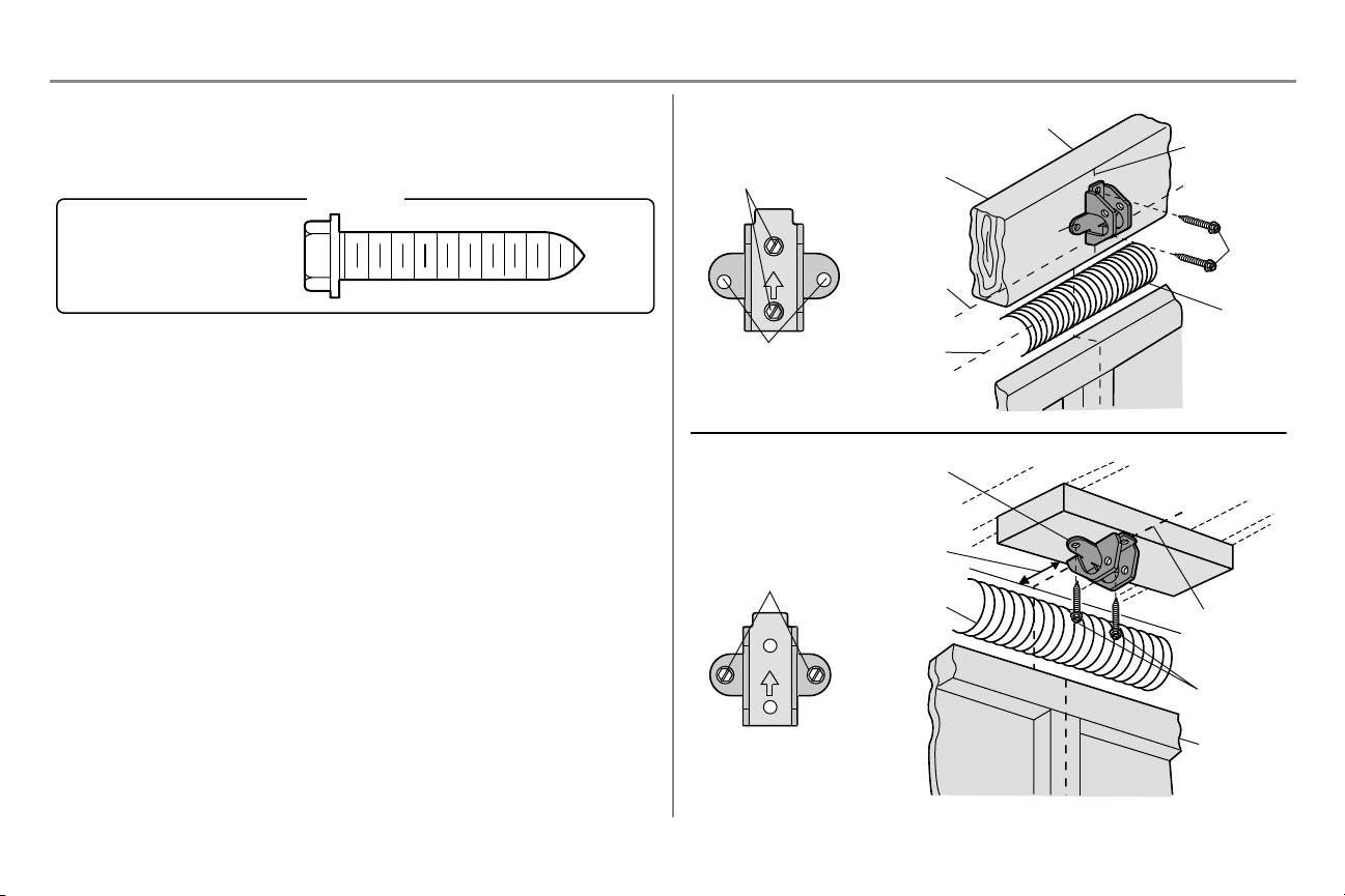
STEP 13 Install the Protector System
®
Be sure power is NOT connected to the garage door opener BEFOR E installing the safety reversing sensor.
To prevent SERIOUS INJURY or D EATH from closing garage door:
l Corr ectly connect and align the safety reversing sensor. This required safety device MUST N OT be
disabled.
l Install the safety reversing sensor so beam is NO HIGHER than 6" (15 cm) above garage floor.
IMPORTAN T INFORMATION ABOUT TH E SA FETY REVERSING SENSORS
The safety reversing sensors must b e connected and aligned correctly befo re the garage doo r o pener will
move in the down direction.
The sending sensor (with an amber LED) transmits an invisi ble li ght beamto the receiving sensor (w ith a green
LED). If an obstruction breaks the light beamwhile the door is closing, the door w ill stop and reverse to the full open
position, and the garage door opener lights will flash 10 times.
NOTE: For energy efficiency the garage door opener w ill enter sleep mode whenthe door is fully closed. The sleep
modeshuts the garage door opener down until activated. The sleep mode is sequenced with the garage door opener
light bulb; as the light bulb turns off the sensor LEDs w ill turn off and w henever the garage door opener lights turn on
the sensor LEDs will light.The garage door opener will not go into the sleep mode until the garage door opener has
completed 5 cycles upon power up.
When installing th e safety reversing sensors check th e following:
l Sensors are installed inside the garage, one on either side of the door.
l Sensors are facing each other wi th the lenses aligned and the r eceiving sensor lens does not receive direct
sunlight.
l Sensors are no more than 6 inches (15 cm) above the floor and the light beam is unobstructed.
The safety reversi ng sensors can be attachedto the door tr ack, the w all, or the floor. The sensors should be no more
than6 inches (15 cm) above the floor. If the door track w ill not support the sensor bracket a w all installation is
recommended.Choose one of the following installations.
OPTION A - DOOR TRACKINSTALLATION
1. Slide the curved arms of the sensor bracket around the edge of the door track. Snap into place so that the
sensor bracket is flush against the track.
2. Slide the carr iage bolt into the slot on each sensor.
3. Insert the bolt through the hole in the sensor bracket and attach with the wing nut. The lenses on both
sensors should point toward each other. Make sure the lens is not obstructed by the sensor bracket.
23
Page 24

Installation
Lens
Carriage
Bolt
(Not provided)
No more than
6 inches (15 cm)
1 2
(Not provided)
Wing Nut
3 4
(Not provided)
I
e
l
l
1 2
Carriage Bolt
Wing Nut
3 4
STEP 13 Install the Protector System®(continued)
OPTION B - WALL INSTALLATION
If additional clearance is neededan extension bracket ( not provided) or wood blocks can be used. Make sure each
bracket has the same amountof clearance so they will align correctly.
1. Position the sensor bracket against the wall with the curved arms facing the door. Make sure there is
enough clearance for the beamto be unobstructed. Mark holes.
2. Dr ill 3/16 inch pilot holes for each sensor bracket and attach the sensor brackets to the wall using lag
screws ( not provided).
3. Slide the carr iage bolt into the slot on each sensor.
4. Insert the bolt through the hole in the sensor bracket and attach with the wing nut. The lenses on both
sensors should point toward each other. Make sure the lens is not obstructed by the sensor bracket.
OPTION C - FLOOR INSTALLATION
Use an extension bracket (not provided) or wood block to raise the sensor bracket if needed.
1. Carefully measure the position of bothsensor brackets so they will be the same distance from the wall and
unobstructed.
2. Attach the sensor brackets to the floor using concrete anchors (not provided).
3. Slide the carr iage bolt into the slot on each sensor.
4. Insert the bolt through the hole in the sensor bracket and attach with the wing nut. The lenses on both
sensors should point toward each other. Make sure the lens is not obstructed by the sensor bracket.
24
Page 25

Installation
Staple
7/16" (11 mm)
WHITE
WHITE
GREY
RED
1
2
3
HARDWARE
Insulated Staple (Not Shown)
STEP 14 Wire the Safety Reversing Sensors
If your garage already has w ires installed for the safety r eversing sensors, proceed to page 26.
OPTION A - INSTALLATION WITHOUT PRE-WIRING
1. Run the wire from both sensors to the garage door opener. Attach the wir e to the wall and ceiling with the
staples.
2. Strip 7/16 inch (11 mm) of insulation from each set of wires. Separatethe wir es. Twist the w hite wi res
together. Twist the w hite/black wires together.
3. Insert the white wires into the w hite terminal on the garage door opener. Insert the white/black wi res into
the grey terminal on the garage door opener. To insert or r emove the wires from the terminal, push in the
tab with a screwdriver tip.
25
Page 26

Installation
Safety reversing
sensor wires
Pre-installed
wires
White
White/Black
Yellow (for example)
Purple (for example)
Wire nuts (not provided)
Pre-installed wires
Safety reversing
sensor wires
1
3
4
7/16" (11 mm)
2
Purple
Yellow
5
7/16" (11 mm)
Yellow
Purple
To insert or remove the wires from the terminal,
push in the tab with a screwdriver tip.
STEP 14 Wire the Safety Reversing Sensors (continued)
OPTION B - PRE-WIRED INSTALLATION
1. Cut the end of the safety reversing sensor wi re, making sure there is enough wire to reach the pre-installed
wir es from the wall.
2. Separate the safety reversing sensor wi res and strip 7/16 inch (11 mm) of insulation from each end.
Choose two of the pre-installed wir es and strip 7/16 inch (11 mm) of insulation from each end. Make sure
that you choose the samecolor pre-installed wir es for each sensor.
3. Connect the pre-installed w ires to the sensor wires with wi re nuts making sure the colors correspond for
each sensor. For example, the white wire w ould connect to the yellow w ire and the w hite/black wire would
connect to the purple wire.
4. At the garage door opener, strip 7/16 inch (11 mm) of insulation fr om each end of the wir es previously
chosen for the safety r eversing sensors. Tw ist the li ke-colored wires together.
5. Insert the wires connected to the white safety sensor wires to the white terminal on the garage door opener.
Insert the w ires that are connectedto the white/black safety sensor wi res to the grey terminal on the garage
door opener.
26
Page 27

Installation
Ground Tab
Green Ground Screw
Ground Wire
White Wire
Black Wire
STEP 15 Connect power
To prevent possible SERIOUS IN JUR Y or D EATH fromelectrocution or fire:
l Be sure power is NOT connected to the opener, and disconnect power to cir cuit BEFORE removing cover to
establish permanentwiring connection.
l Garage door installation and wiring MUST be in compliance with ALL l ocal electrical and building codes.
l NEVER use an extension cord, 2-wire adapter, or change plug in ANY way to make it fit outlet. Be sure the
opener is grounded.
To avoid installation difficulties, do not run t he opener at this time.
To r educe the risk of electric shock, your garage door opener has a grounding type plug with a third grounding pin.
This plug w ill only fit into a grounding type outlet. If the plug doesn’t fit into the outlet you have, contact a qualified
electrician to install the proper outlet.
THER E A RE TWO OPTIONS FOR CON NECT ING POWER:
OPTION A - TYPICAL WIRING
1. Plug in the garage door opener into a grounded outlet.
2. DO N OT run garage door opener at this time.
OPTION B - PERMANENTWIRING
If permanent wiring is requ ired b y your local code, refer to the following procedure. To make a p ermanent
connection thro ugh t he 7/8 inch ho le in the top of the motor un it (according to local code):
1. Remove the motor unit cover screws and set the cover aside.
2. Remove the attached 3-prong cord.
3. Connect the black ( line) wire to the screw on the brass terminal; the white (neutral) wire to the screw on
the silver terminal; and the ground wire to the greengroundscrew. The opener must b e gro unded.
4. Reinstall the cover.
27
Page 28

Installation
Green LED
Amber LED
Wing Nut
SENDING SENSOR
RECEIVING SENSOR
(invisible light beam)
If the receiving sensor is in direct
sunlight, switch it with sending sensor so
it is on the opposite side of the door.
RED
WHITE
GREY
3
2
1
1
2
STEP 16 Aligning the safety reversing sensors
The door will no t close if t he sensors have n ot been installed and aligned correctly.
Whenthe light beam is obstructed or misaligned whil e the door is cl osing, the door will reverse and the garage door
opener lights will flash ten times. If the door is already open,it w ill not close.
1. Check to make sure the LEDs in both sensors are glowing steadily. T he LEDs in both sensors will glow
steadily i f they are alignedandwired correctly.
The sensors can be aligned by loosening the wing nuts, aligningthe sensors, and tightening the wing nuts.
IF THE AMBER LED ON THE SENDING SENSOR IS N OT GLOWING:
1. Make sure there is power to the garage door opener.
2. Make sure the sensor wire is not shorted/broken.
3. Make sure the sensor has beenwir ed correctly: w hite wires to w hite terminal and white/black wires to
grey terminal.
IF THE GREEN L ED ON THE RECEIVING SENSOR IS N OT GLOWING:
1. Make sure the sensor wire is not shorted/broken.
2. Make sure the sensors are aligned.
STEP 17 Ensure the door control is wired correctly
If the door control has been installed and wired corr ectly, the command LED on the Multi-Function Control Panel will
blink.
28
Page 29

Adjustments
UP (Open)
DOWN (Close)
Correct
Incorrect
UP Button
Adjustment Button
DOWN Button
PROGRAMMING BUTTONS
Introduction
Withouta properly installed safety reversal system, persons (particularly small children) could be SERIOUSLY
INJURED or KILLED by a closing garage door.
l Incorrect adjustment of garage door travel limits w ill interfere wi th proper operation of safety r eversal
system.
l After ANY adjustments are made, the safety reversal system MUST be tested. Door MUST reverse on
contact with 1-1/2" ( 3.8 cm) high object (or 2x4 laid flat) on floor.
To prevent damage to vehicles, be sure fully open door provides adequate clearance.
Your garage door opener is designed with electronic controls to make setup and adjustments easy. The adjustments
allow you to program w here the door wi ll stop in the open (U P) and close (D OWN) position. The electronic controls
sense the amountof force required to open and close the door. T he force is adjusted automatically w hen you program
the travel.
NOTE: If anything interferes with the door’s upward travel it will stop. If anything interferes with the door’s downward
travel, it will reverse.
One-Piece Doors Only
Whensetting the UP travel for a one-piece door ensure that the door does not slant backwards when fully open (UP).
If the door is sl anted backwards this w ill cause unnecessary bucking and/or jerking whenthe door is opening or
closing.
ProgrammingButtons
The programming buttons are located on the left side panel of the garage door opener and are used to program the
travel. While programming, the UP and D OWN buttons can be used to move the door as needed.
29
Page 30

Adjustments
UP Button
Adjustment Button
DOWN Button
PROGRAMMING BUTTONS
1 2
3
4 5
6 7
STEP 1 Program the Travel
Withouta properly installed safety reversal system, persons (particularly small children) could be SERIOUSLY
INJURED or KILLED by a closing garage door.
l Incorrect adjustment of garage door travel limits w ill interfere wi th proper operation of safety r eversal
system.
l After ANY adjustments are made, the safety reversal system MUST be tested. Door MUST reverse on
contact with 1-1/2" ( 3.8 cm) high object (or 2x4 laid flat) on floor.
While programming, the UP and DOWN buttons can be used to move the door as needed.
1. Press and hold the AdjustmentButton until the UP Button begins to flash and/or a beep is heard.
2. Press and hold the UP Button until the door i s in the desired U P position.
3. Once the door is in the desired U P position press and release the Adjustment Button. The garage door
opener lights will flash twice and the D OWN Button will begin to flash. IMPORTAN T NOTE: For one-
piece door installations refer to page 29.
4. Press and hold the DOWN button until the door is in the desir ed DOWN position.
5. Once the door is in the desired D OWN position press and release the AdjustmentButton. The garage door
opener lights will flash twice and the U P Button will begin to flash.
6. Press and r elease the UP Button. When the door travels to the programmed UP position, the D OWN Button
will begin to flash.
7. Press and r elease the DOWN Button. The door will travel to the programmedD OWN position.
Programmingis complete.
* If the garage door opener lights are flashing 5 times during the steps for Program the Travel, the programming has
timed out. If the garage door opener lights are flashing 10 times during the steps for Program the Travel, the safety
reversing sensors are misaligned or obstructed (refer to page 28). When the sensors are aligned and unobstructed,
cycle the door through a complete up and down cycle using the remote control or the UP and DOWN buttons.
Programmingis complete.If you are unable to operate the door up and down, repeat the steps for Programming the
Travel.
To w atch a video, go to tinyurl.com/lkwbnhj
30
Page 31

Adjustments
1 2
1
2
STEP 2 Test the Safety Reversal System
Withouta properly installed safety reversal system, persons (particularly small children) could be SERIOUSLY
INJURED or KILLED by a closing garage door.
l Safety reversal system MUST be tested every month.
l After ANY adjustments are made, the safety reversal system MUST be tested. Door MUST reverse on
contact with 1-1/2" ( 3.8 cm) high object (or 2x4 laid flat) on the floor.
The second paragraph contained instructions that are no longer correct and was replaced with the list of steps if the
test fails. Per regulatory and Lisa R. Change is being madeto the commonsnippet.It has not beenimplemented in any
documents yet. MDR
Addedl ast sentence to snippet per Lisa. MDR
1. With the door fully open, place a 1-1/2inch (3.8 cm) board (or a 2x4 l aid flat) on the floor, centered under
the garage door.
2. Press the r emote control push button to close the door. The door MUST reverse w hen it makes contact
with the board.
If the door stops but does not reverse:
1. Review the installation instructions provided to insure all steps were followed;
2. Repeat Program the Travel (see Adjustment Step 1);
3. Repeat the Safety R eversal test.
If the test continues to fail, call a trained door systems technician.
STEP 3 Test the Protector System
Withouta properly installed safety reversing sensor, persons (particularly small children) could be SERIOUSLY
INJURED or KILLED by a closing garage door.
1. Open the door. Place the garage door opener carton in the path of the door.
2. Press the r emote control push button to close the door. The door will not move more than an inch (2.5 cm),
and the garage door opener lights will flash 10 times.
The garage door opener wi ll not close from a remote control if the LED in either safety reversing sensor is off (alerting
you to the fact that the sensor is misaligned or obstructed). If the garage door opener closes the door when the safety
reversing sensor is obstructed (andthe sensors are no more than 6inches [15 cm] above the floor), call for a trained
door systems technician.
®
31
Page 32

Operation
Changed"Important Installation Instructions to "Important Safety Instructions". For 114a5010 MDR
IMPORTANT SAFETY INSTRUCTIONS
To reduce the risk of SEVERE INJURY or DEATH:
1. READ AND FOLLOW ALL WARNIN GS AND INSTR UCTIONS.
2. ALWAYS keep remote controls out of reach of children. NEVER permit children to operate or play with garage
door control push buttons or remote controls.
3. ONLY activate garage door when it can be seenclearly, it is properly adjusted, and there are no obstructions
to door travel.
4. ALWAYS keep garage door in sight and away from people and objects until completely closed. NO ONE
SHOULD C ROSS THE PATH OF THE MOVING DOOR.
5. NO ON E SH OULD GO UNDER A STOPPED, PARTIALLY OPENED D OOR.
6. If possible, use emergency r elease handle to disengage trolley ONLY when garage door is C LOSED. U se
caution when using this release with the door open.Weak or broken springs or unbalanced door could result in
an open door falling rapidly and/or unexpectedly and incr easing the ri sk of SEVERE INJURY or D EATH.
7. NEVER use emergency release handle unless garage doorway is clear of persons and obstructions.
8. NEVER use handle to pull garage door open or closed. If rope knot becomes untied, you could fall.
9. After ANY adjustments are made, the safety reversal system MUST be tested.
10. Safety reversal system MUST be tested every month. Garage door MUST reverse on contact with 1-1/2"
(3.8 cm) high object (or a 2x4 laid flat) on the floor. Failure to adjust the garage door opener properly
increases the risk of SEVERE INJURY or D EATH.
11. ALWAYS KEEP GARAGE DOOR PROPERLY BALANCED (see page 2). An improperly balanced door
may NOT reverse whenrequired and could result in SEVERE INJU RY or DEATH.
12. ALL repairs to cables, spring assemblies and other hardware, ALL of which are under EXTREME tension,
MUST be made by a traineddoor systems technician.
13. ALWAYS disconnect electric power to garage door opener BEFORE making ANY repairs or r emoving
covers.
14. This operator system is equippedwith an unattended operation feature. The door could move
unexpectedly. N O ON E SH OULD C ROSS THE PATH OF THE MOVING DOOR.
15. DO NOT install on a one-piece door if using devices or features providing unattendedclose. U nattended
devices and features are to be used ONLY with sectional doors.
16. SAVE THESE INSTRUCTIONS.
32
Page 33

Operation
Features
Your garage door opener is equipped with features to provide you with greater control over your garage door
operation.
®
MyQ
MyQ®technology uses a 900MHz signal to provide two-w ay communication between the garage door opener and
MyQ®enabled accessories. Your garage door opener is compatible with up to 8 MyQ®accessories. For Smartphone
App control of your garage door opener and other MyQ®accessories, Chamberlain's MyQ®InternetGateway (model
CIGBU) is required.
TIMER-TO-CLOSE (DO NOT enable on one-piece doors)
The Timer-to-Cl ose feature is not available on all door controls. Below is a list of door controls w ith the Timer-toClose feature:
041A7305-1 Smart Control Panel and 041A7327-1 Motion Detecting Control Panel
The Timer-to-Cl ose feature automatically closes the garage door after a specified time period. D O NOT enable TTC
if operating a one-piece do or. TTC is to be used ONLY with sectional doors. F actory default is set to off. The
garage door opener will beep and the li ghts will flash before closing the door. The TTC feature will deactivate if the
garage door encounters an obstruction twice; or the safety reversi ng sensors are incorrectly installed. The garage
door will reverse open and WILL NOT close until the obstructions are clear or the safety reversing sensors are
correctly installed. When the obstruction has beencleared or the safety reversing sensors have been aligned, the door
will close when the garage door opener is activated. TTC WILL NOT work i f the garage door opener is operating by
battery power or if the safety reversi ng sensors are misaligned. This feature is N OT intendedto be the primary
method of closing the door. A keylessentry should be installed in the event of an accidental lock out when
using this feature.
REMOTE CONTROLS ANDDOOR CONTROLS (MyQ®)
Your garage door opener has already been programmed at the factory to operate with your remote control, which
changes with each use, randomly accessing over 100 billi on new codes. Compatible with MyQ®enabled accessories,
see page 41.
NOTE: Older Chamberlain r emote controls, door controls, and third party products are not compatible.
MyQ®Accessories
Remote Controls Up to 8
Door Controls
Keyless Entries Up to 1
MEMORY CA PACITY
Up to 2 MyQ®door controls
THE PROTECTOR SYSTEM®(SAFETY REVERSING SENSORS)
Whenproperly connected and aligned, the safety reversi ng sensors wi ll detect an obstruction in the path of the
infrared beam. If an obstruction breaks the infrared beamwhile the door is closing, the door will stop and reverse to
full open position, and the opener lights will flash 10 times. If the door is fully open, and the safety reversi ng sensors
are not installed, or are misaligned, the door will not close from a remote control. However, you can close the door if
you hold the button on the door control or keyless entry until the door is fully closed. The safety reversi ng sensors do
not effect the opening cycle.
ENERGY CONSERVATION
For energy efficiency the garage door opener will enter sleep mode when the door is fully closed. The sleep mode
shuts the garage door opener down until activated. The sleep mode is sequenced with the garage door opener light
bulb; as the light bulb turns off the sensor LEDs w ill turn off and w henever the garage door opener lights turn on the
sensor LEDs w ill l ight. The garage door opener will not go into the sleep modeuntil the garage door opener has
completed 5 cycles upon power up.
LIGHTS
The garage door opener light bulbs will turn on whenthe opener is initially plugged in; power is r estored after
interruption, or whenthe garage door opener is activated. The lights will turn off automatically after 4-1/2 minutes. An
incandescent A19 light bulb (100 w att maximum) or for maximum energy efficiency a 26W (100W equivalent) compact
fluorescent light (CF L) bulb may be used. NOT E: Do not use halogen, short neck, or specialty light bulbs as these
may overheat the end panel or light socket. Do not use LED bulbs as they may reduce the r angeor performance of
your remote controls.
Light Feature
The garage door opener is equipped with an added feature; the lights will turn on whensomeone enters through the
opengaragedoor and the safety reversi ng sensor infrared beamis broken. For added control over the light bulbs on
your garage door opener, see page 34.
33
Page 34

Operation
Push Bar
LIGHT Button
LOCK Button
Command LED
LEARN Button
Using your Garage Door Opener
The garage door opener can be activated through a w all-mounteddoor control, remote control, wireless keyless entry
or MyQ®accessory.
Whenthe door is closed and the garage door opener is activatedthedoor will open. If the door senses an obstruction
or is interrupted while opening the door will stop. When the door is in any position other than closed and the garage
door opener is activatedthe door will close. If the garage door opener senses an obstruction while closing, the door
will reverse. If the obstruction interr upts the sensor beam the garage door opener lights will blink 10 times. However,
you can close the door if you hold the button on the door control or keyless entry until the door is fully closed.
The safety reversi ng sensors do not affect the openingcycle. The safety reversing sensor must be connected and
aligned correctly before the garage door opener w ill move in the down dir ection.
Multi-Function Control Panel
SYNCHRONIZE THE DOOR CONTROL
To synchronize the door control to the garage door opener, press the push bar until the garage door opener activates
(it may take up to 3 presses). T est the door control by pressing the push bar, each press of the push bar will activate
the garage door opener.
MULTI-FUNCTION CONTROL PANEL FEATURES
PUSH BAR
Press the push bar to openor close the door.
LIGHTS
Light Button
Press the LIGHT button to turn the garage door opener lights on or off. When the l ights are turned on they will stay on
until the LIGHT button is pressed again, or until the garage door opener is activated. Once the garage door opener is
activated the lights wil l turn off after the specified period of time (the factory settingis 4-1/2 minutes). The LIGHT
button will not control the lights whenthe door is in motion.
To change th e amount of time the garage door o pener lights will stay on:
Press and hold the LOCK button ( approximately 10 seconds) until the garage door opener lights flash. T he time
interval is indicated by the number times the garage door opener flashes:
l 1 flash is 1-1/2minutes
l 2 flashes is 2-1/2 minutes
l 3 flashes is 3-1/2 minutes
l 4 flashes is 4-1/2 minutes
To cycle through the time intervals repeat the step above.
Light Feature
The lights wi ll turn on whensomeone enters through the open garage door and the safety r eversing sensor i nfrared
beami s broken.
l Deactivate: Press and hold the LIGHT button (approximately 10 seconds) until the garage door opener
lights turn on, then off again.
l Activate: Start wi th the garage door opener lights on. Press and hold the LIGHT button (approximately 10
seconds) until the garage door opener lights turn off, then on again.
If the commandLED is continuously blinking, the LOCK feature needs to be deactivated.
34
Page 35

Operation
Push Bar
LIGHT Button
LOCK Button
Command LED
LEARN Button
The command LED
will flash once.
The command LED will
flash once again.
1
2
OR
PIN
? ? ? ?
3
Multi-Function Control Panel (continued)
LOCK
The LOCK feature is designed to prevent activation of the garage door opener from r emote controls w hile still allowing
activation from the door control and keyless entry. This feature is useful for added peace of mind when the home is
empty (i.e. vacation).
l Activate: Press and hold the LOCK button for 2 seconds. The command LED wi ll flash as long as the lock
feature is activated and your handheld remote control w ill not operateyour door at this time.
l Deactivate: Press and hold the LOCK buttonagain for 2 seconds. The command LED will stop flashing
and normal operation wi ll resume.
PROGRAM
Any compatible remote controls, wireless keyless entry, or MyQ®accessories can be programmedto the garage door
opener by pressing the Learn button.
Remote Control and Keyless Entry*
Pre-prog rammed remote cont rol included, no n eed to program t he remote.
To add or reprogram a remote control, follow the instructions below. Older Chamberlain remote controls are N OT
compatible, see page41 for compatible accessories.
PROGRAM USING THE DOOR CONTROL
1. Press the LEARN buttonon the door control to enter Programming Mode.
2. Press the LEARN buttonagain, the LED will flash once.
3. Remote C ont rol: Press the button on the r emote control that you wish to operate your garage door.
KeylessEntry: Enter a 4-digit personal identification number (PIN) of your choice on the keyless entry
keypad. Then press the EN TER button.
The garage door opener lights will flash ( or two clicks will be heard) whenthe code has been programmed.
* N ot included w ith all models.
35
Page 36

Operation
LEARN LED
LEARN
Button
“click”
“click”
1-2 3
PIN
Remote Control (continued)
PROGRAM USING THE LEARN BUTTON
1. Locate the Learn Button.
2. Press and immediately release the Learn button.The Learn LED w ill glow steady for 30 seconds. Within 30
seconds...
3. Remote C ont rol: Press and hold the buttonon the remote control that you w ish to use.
KeylessEntry: Enter a 4-digit personal identification number (PIN) of your choice on the keyless entry
keypad. Then press and hold the ENTER button.
Release the button when the garage door opener li ghts blink or two clicks are heard. When replacing the light lens
cover, ensure the antennawires are hanging straight down.
To w atch a video, go to tinyurl.com/lcsf6xt
HomeLink
If your vehicle is equipped with HomeLink, a Compatibility BridgeTM(not included) may be necessary for certain
vehicles. Visit bridge.chamberlain.com to find out i f a Bridgeis needed.
®
To Erase the Memory
ERASE ALL REMOTE CONTROLS AND KEYLESS ENTRIES
1. Press and hold the LEARN button on garage door opener until the learn LED goes out (approximately 6
seconds). All remote control and keyless entry codes are now erased. Reprogram any accessory you wish
to use.
ERASE ALL DEVICES (IncludingMyQ®enabledaccessories)
1. Press and hold the LEARN button on garage door opener until the learn LED goes out (approximately 6
seconds).
2. Immediately press and hold the LEARN buttonagain until the learn LED goes out. All codes are now
erased. Reprogram any accessory you wish to use.
36
Page 37

Operation
To Open the Door Manually
To prevent possible SERIOUS IN JUR Y or D EATH froma falling garage door:
l If possible, use emergency r elease handle to disengage trolley ONLY when garage door is C LOSED. Weak
or broken springs or unbalanceddoor could result in an open door falling rapidly and/or unexpectedly.
l NEVER use emergency release handle unless garage doorway is clear of persons and obstructions.
l NEVER use handle to pull door open or closed. If rope knot becomes untied, you could fall.
DISCONNECTTHE TROLLEY
1. The door should be fully closed if possible.
2. Pull down on the emergency release handle so the trolley release arm snaps to the vertical position. The
door can now be raised and lowered as oftenas necessary.
TO RE-CONNECT THE TROLLEY
1. Pull the emergency release handle toward the garage door opener so the trolley release arm snaps to the
horizontal position. The trolley w ill reconnect on the next UP or DOWN operation, either manually or by
using the door control or remote control.
37
Page 38

Maintenance
1
2
3
Maintenance Schedule
EVERY MONTH
l Manually operate door. If it is unbalanced or binding, call a trained door systems technician.
l Check to be sure door opens and closes fully. Adjust if necessary, see page 29.
l Test the safety reversal system. Adjust if necessary, see page 31.
EVERY YEA R
l Oil door rollers, bearings and hinges. The garage door opener does not r equire additional lubrication. Do not
grease the door tracks.
NOTIC E: This device complies with Part 15 of the FCC rules and Industry Canada’s license-exemptRSSs.
Operation is subject to the following two conditions: (1) this device may not cause harmful interference, and (2) this
device must accept any interference received, including interference that may cause undesired operation.
Any changes or modifications not expressly approved by the party responsible for compliance could void the user’s
authority to operate the equipment.
This device must be installed to ensure a minimum 20 cm (8 in.) distance is maintainedbetween users/bystanders
and device.
This device has been tested and found to comply with the limits for a Class B digital device, pursuant to part 15 of
the FCC rules and Industry Canada ICES standard. These limits are designed to provide r easonable protection
against harmful interference i n a residential installation. This equipment generates, uses and can radiate radio
frequency energy and, if not installed and used in accordance w ith the i nstructions, may cause harmful interference
to radio communications. H owever, there is no guarantee that interferencewill not occur in a particular installation.
If this equipment does cause harmful interference to radio or television reception, which can be determinedby
turning the equipment off and on, the user is encouraged to try to corr ect the interference by one or more of the
following measures:
l Reorient or relocate the r eceiving antenna.
l Increase the separation between the equipmentandreceiver.
l Connect the equipment intoan outlet on a cir cuit differentfrom that to w hich the receiver i s connected.
l Consult the dealer or an experienced radio/TV technician for help.
The Remote Control Battery
To prevent possible SERIOUS IN JUR Y or D EATH:
l NEVER allow small chil dren near batteries.
l If battery is swallowed, immediately notify doctor.
To r educe risk of fire, explosion or chemical burn:
l Replace ON LY with 3V CR2032 coin batteries.
l DO NOT recharge, disassemble, heat above 212°F ( 100°C) or incinerate.
The 3V CR 2032Lithiumbattery should produce power for up to 3
years. If the battery is low, the r emotecontrol’s LED will not flash
when the button is pressed.
To r eplace battery, pry openthecase fir st in the middle (1), then at
each side (2 and 3) wi th the visor clip. Replace the batteries with only
3V CR2032 coin cell batteries. Insert battery positive side up. Dispose
of old batteries properly.
38
Page 39

Troubleshooting
Diagnostic Chart
Your garage door opener is programmed with self-diagnostic capabilities. The U P and D OWN arrows on the garage door opener flash the diagnostic codes.
DIAGNOSTICCODE SYMPTOM SOLUTION
Up Arrow
Flash(es)
1 1
1 2
1 3
1 4
1 5
1 6
2 1-5
3 2
Down Arrow
Flash(es)
The garage door opener wi ll not close and the light bulbs flash. Safety reversi ng sensors are not installed, connected, or w ires may be cut. Inspect sensor w ires for a disconnected
or cut w ire.
The garage door opener wi ll not close and the light bulbs flash. There i s a short or reversed wire for the safety r eversing sensors. Inspect safety sensor wir e at all staple and
connectionpoints, replace w ire or correct as needed.
The door control will not function. The wires for the door control are shorted or the door control is faulty. Inspect door control w ires at all staple and
connectionpoints, replace w ire or correct as needed.
The garage door opener wi ll not close and the light bulbs flash. Safety reversi ng sensors are misaligned or were momentarily obstructed.Realign both sensors to ensure both LEDs
are steady and not flickering. Make sure nothing is hanging or mounted on the door that would interrupt the sensor’s
pathwhile closing.
Door moves 6-8" ( 15-20 cm) stops or reverses. Manually open and close the door. C heck for binding or obstructions, such as a broken spring or door lock, correct as
needed. Check wiring connections at travel module and at the l ogic board. R eplace travel module if necessary.
No movement, only a single click. Manually open and close the door. C heck for binding or obstructions, such as a broken spring or door lock, correct as
needed. Replace logic board if necessary.
Opener hums for 1-2 seconds no movement. Manually open and close the door. C heck for binding or obstructions, such as a broken spring or door lock, correct as
needed. Replace motor if necessary.
Door coasts after it has cometo a complete stop. Program travel to coasting position or have door balanced by a trained door systems technician.
No movement, or sound. Replace logic board.
Unable to set the tr avel or r etain position. Check travel module for proper assembly, replace if necessary.
39
Page 40

Troubleshooting
DIAGNOSTICCODE SYMPTOM SOLUTION
Up Arrow
Flash(es)
4 1-4
4 5
4 6
Down Arrow
Flash(es)
Door is moving stops or reverses. Manually open and close the door. C heck for binding or obstructions, such as a broken spring or door lock, correct as
Opener runs approximately 6-8" ( 15-20 cm), stops and r everses. Communication error to travel module. Check travel module connections, replace travel module if necessary.
The garage door opener wi ll not close and the light bulbs flash. Safety r eversing sensors are misaligned or were momentarily obstructed. R ealign both sensors to ensure both LEDs
needed. If the door is binding or sticking contact a trained door systems technician. If door is not binding or sticki ng
attempt to r eprogram travel (r efer to page page30).
are steady and not flickering. Make sure nothing is hanging or mounted on the door that would interrupt the sensor’s path
while closing.
The garage door opener can beep for several reasons:
l Garage door opener has been activated through a device or feature such as Timer-to-Close or garage door
monitor, see page page 33.
My remote cont rol will no t activate t he g arage door:
l Verify the lock feature i s not activated on the door control.
l Reprogram the r emote control.
l If the r emote control will still not activate the door check the diagnostic codes to ensure the garage door opener
is working properly.
My doo r will not close and t he light bulbs blink on my mo tor unit:
The safety reversi ng sensor must be connected and aligned correctly before the garage door opener w ill move in the
down direction.
l Verify the safety reversing sensors are properly installed, aligned and free of any obstructions.
My garage door opener light(s) will not turn off when the door is open:
The garage door opener is equipped with a feature that turns the lighton when the safety reversing sensors have been
obstructed. These features can be disabled using the door control, see page page 34.
My neighbor’s remote con trol opens my garage door:
Erase the memory from your garage door opener and reprogramthe remote control(s) .
My vehicle's Homelink®is not programming to my garage door opener:
Compatibility BridgeTM(not included) may be necessary for certain vehicles. Visit bridge.chamberlain.com to find out if
a Bridge is needed.
40
Page 41

Accessories
8808CB-P
8810CB-P
940EV-P2 Wireless Keypad:
8 Foot (2.4 m) Rail
Extension:
To allow an 8 foot (2.4 m)
door to open fully.
10 Foot (3 m) Rail
Extension:
To allow a 10 foot (3 m) door
to open fully.
For use outside of the home
to enable access to the garage
using a 4-digit PIN. Works
with ALL Chamberlain openers
from 1993-present. MyQ®
compatible.
041A5281-1
CLLP1-P Laser Parking Assistant:
CLSS1-P
Extension Brackets:
(Optional) For safety reversing
sensor installation onto the
wall or fl oor.
Park in the right spot every
time! A laser beam is
activated by your garage door
opener and projected on to
the dashboard of your vehicle
to guide perfect parking.
System Surge Protector:
The Garage Door Opener
Surge Protector is designed
to protect Chamberlain garage
door openers against damage
from lightning and power
surges. Easy to install.
953EV-P2
956EV-P2 Keychain Remote Control:
Remote Control:
Works with ALL Chamberlain
openers from 1993-present.
MyQ® compatible. Includes
visor clip.
Works with ALL Chamberlain
openers from 1993-present.
MyQ® compatible. With key
ring.
MyQ® Accessories
PILCEV-P1 MyQ® Remote Lamp Control:
WSLCEV-P1 MyQ
Monitor and control this plug
in lamp switch with the MyQ
Smartphone App.
®
Interior/Exterior
Light Switch:
Monitor and control this wall
light switch with the MyQ®
Smartphone App.
®
41
Page 42

Warranty
This garage door opener WILL NOT work until the
safety reversing sensors are properly installed and aligned.
➞
➞
Contact Information
STOP!
For installation and service information call:
1-800-528-9131
If you are calling about a Troubleshooting issue, it is recommended that you have access to your
Before calling, please have the model number of the garage door opener.
garage door opener while calling.
If you are ordering a repair part please have the following information:
part number, part name, and model number.
42
Page 43

The Chamberlain Group, Inc.
workmanship for a specific period of time as defined below (the “Warranty Period”). The warranty period commences from the date of purchase.
®
(“Seller”) warrants to the first retail purchaser of this product, for the residence in which this product is originally installed, that it is free from defects in materials and/or
CHAMBERLAIN
®
LIMITED WARRANTY
WARRANTY PERIOD
Parts Motor Accessories Belt
1 Year 10 Years 1 year 15 Years
The proper operation of this product is dependent on your compliance with the instructions regarding installation, operation, and maintenance and testing. Failure to comply strictly with those instructions will void
this limited warranty in its entirety. If, during the limited warranty period, this product appears to contain a defect covered by this limited warranty, call 1-800-528-9131, toll free, before dismantling this product.
You will be advised of disassembly and shipping instructions when you call. Then send the product or component, pre-paid and insured, as directed to our service center for warranty repair. Please include a brief
description of the problem and a dated proof-of-purchase receipt with any product returned for warranty repair. Products returned to Seller for warranty repair, which upon receipt by Seller are confirmed to be
defective and covered by this limited warranty, will be repaired or replaced (at Seller’s sole option) at no cost to you and returned pre-paid. Defective parts will be repaired or replaced with new or factory rebuilt
parts at Seller’s sole option. [You are responsible for any costs incurred in removing and/or reinstalling the product or any component.]
ALL IMPLIED WARRANTIES FOR THE PRODUCT, INCLUDING BUT NOT LIMITED TO ANY IMPLIED WARRANTIES OF MERCHANTABILITY AND FITNESS FOR A PARTICULAR PURPOSE, ARE LIMITED IN
DURATION TO THE APPLICABLE LIMITED WARRANTY PERIOD SET FORTH ABOVE FOR THE RELATED COMPONENT(S), AND NO IMPLIED WARRANTIES WILL EXIST OR APPLY AFTER SUCH PERIOD. Some
States do not allow limitations on how long an implied warranty lasts, so the above limitation may not apply to you. THIS LIMITED WARRANTY DOES NOT COVER NON-DEFECT DAMAGE, DAMAGE CAUSED
BY IMPROPER INSTALLATION, OPERATION OR CARE (INCLUDING, BUT NOT LIMITED TO ABUSE, MISUSE, FAILURE TO PROVIDE REASONABLE AND NECESSARY MAINTENANCE, UNAUTHORIZED REPAIRS
OR ANY ALTERATIONS TO THIS PRODUCT), LABOR CHARGES FOR REINSTALLING A REPAIRED OR REPLACED UNIT, REPLACEMENT OF CONSUMABLE ITEMS (E.G., BATTERIES IN REMOTE CONTROL
TRANSMITTERS AND LIGHT BULBS), OR UNITS INSTALLED FOR NON-RESIDENTIAL USE. THIS LIMITED WARRANTY DOES NOT COVER ANY PROBLEMS WITH, OR RELATING TO, THE GARAGE DOOR OR
GARAGE DOOR HARDWARE, INCLUDING BUT NOT LIMITED TO THE DOOR SPRINGS, DOOR ROLLERS, DOOR ALIGNMENT OR HINGES. THIS LIMITED WARRANTY ALSO DOES NOT COVER ANY PROBLEMS
CAUSED BY INTERFERENCE. UNDER NO CIRCUMSTANCES SHALL SELLER BE LIABLE FOR CONSEQUENTIAL, INCIDENTAL OR SPECIAL DAMAGES ARISING IN CONNECTION WITH USE, OR INABILITY TO
USE, THIS PRODUCT. IN NO EVENT SHALL SELLER’S LIABILITY FOR BREACH OF WARRANTY, BREACH OF CONTRACT, NEGLIGENCE OR STRICT LIABILITY EXCEED THE COST OF THE PRODUCT COVERED
HEREBY. NO PERSON IS AUTHORIZED TO ASSUME FOR US ANY OTHER LIABILITY IN CONNECTION WITH THE SALE OF THIS PRODUCT.
Some states do not allow the exclusion or limitation of consequential, incidental or special damages, so the above limitation or exclusion may not apply to you. This limited warranty gives you specific legal rights,
and you may also have other rights, which vary from state to state.
43
Page 44

Automatic Garage Door Opener Safety & Maintenance Guide
Garage Door Opener Safety – An Automatic Decision
A garage door is the largest moving object in the home. An improperly adjusted garage door and opener can exert deadly force when the door closes – which could lead to
entrapment of children or adults and subsequent injury or death.
Proper installation, operation, maintenance, and testing of the garage door and automatic opener are necessary to provide a safe, trouble-free system. Careless operation or allowing
children to play with or use garage door opener controls are also dangerous situations that can lead to tragic results. A few simple precautions can protect your family and friends from
potential harm. Please review the safety and maintenance tips in this guide carefully and keep it for reference. Check the operation of your garage door and opener to ensure they function in
a safe and trouble-free manner. Be sure to read all Important Safety Information found in your garage door opener’s manual as it provides more details and safety considerations than can
be supplied with this guide.
Garage Door Openers are Not Toys
Discuss garage door and opener safety with your children. Explain the danger of being trapped under the door.
Stay away from a moving door.
Keep transmitters and remote controls out of
reach of children. Do not let children play with or
use transmitters or other remote control devices.
The wall-mounted push button should be out of
reach of children, at least 5 feet from the nearest
standing surface and away from all moving parts.
Mount and use the button where you can clearly see
the closing garage door.
Keep the door in sight until it completely closes
when using the wall-mounted push button or
transmitter.
44
Page 45

Routine Maintenance Can Prevent Tragedies
1
2
Make monthly inspection and testing of your garage door and opener system a part of your regular routine. Review your owner’s manual for both the door and door opener. If you don’t
have the owner’s manuals, contact the manufacturer(s) and request a copy for your specifi c model(s). Look for the opener model number on the back of the power unit.
WARNING – Springs are under high tension. Only qualifi ed individuals should adjust them.
Visually check the door and installation:
• Starting with the door in the closed position, use the manual disconnect on the opener to
disconnect the door.
• Look for signs of wear or damage on hinges, rollers, springs, and door panels.
• These parts may require periodic lubrication. Check the owner’s manual for suggested maintenance.
• If any signs of damage are evident, contact a trained door systems technician for assistance.
• Verify the photoeye height is no higher than 6” from the garage fl oor.
Test the door for proper operation:
• Open and close the door manually using handles or suitable gripping points.
• The door should move freely and without diffi culty.
• The door should balance and stay partially open 3–4 feet above the fl oor.
• If you detect any signs of improper operation, contact a trained door systems technician
for assistance.
Test the opener safety features:
• Reconnect the opener to the door using the manual disconnect and open the door.
• Place a 2x4 board fl at in the path of the door (1) and try to close it (2). The door should stop
when it comes in contact with the 2x4 and then reverse direction.
• Block the photoelectric sensor by waving an object in front of the sensor and attempt
to close the door. The door should not close unless the wall-mounted push button is
manually held during operation.
• If the opener does not perform as described, contact a trained door systems technician
for assistance.
45
Page 46

Repair Parts
2
Rail Assembly Parts Installation Parts
Description Part Number
1 Belt 041A5250
2 Pulley 144C0054M
3 Master Link 004A1008
4 Rail 041A5665
5 Trolley Assembly
Includes:
Threaded Shaft (1),
Clevis Pin (1), Ring (1).
6 “U” Bracket 041D0598-1
Not Shown
Wear Pads 041A7276
Hardware Bag 041A7920-2
041C5141-2
2
1
Description Part Number
3
1 Curved Door Arm 041B0035B
2 Door Bracket with Clevis
041A5047-1
Pin and Fastener
3 Emergency Release Rope
3
and Handle
4 Header Bracket with Clevis
Pin and Fastener
5 Remote Control
4
5
6
Visor Clip
6 Safety Sensor Bracket 041A5266-3
7 Safety Sensor Kit Receiving
and sending sensors with
wire
041A2828
041A5047-2
K029B0137
041A5034
11
9
1
4
7
6
8 Straight Door Arm 4178B0034B
9 White and Red/White Wire 041B4494-1
10 3V CR2030 Lithium Battery K010A0020
8
5
11 Hanging Brackets 012B0776
Not Shown
10
Owner’s Manual 114A5009
46
Page 47

Repair Parts
Garage Door Opener Parts
4
5
11
Description Part Number
1 Sprocket Cover 041A4371
2 Gear and Sprocket 041A4885-5
1
2
12
10
8
9
14
6
7
13
3
4
5
3 End Panel with Light Socket 041A7760
4 Light Socket 041C0279
5 Light Lens 041D7572
6 Capacitor 030B0532-1
7 Capacitor Bracket K012A0373
8 Travel Module 041D7742-7
9 Cover 041D8810
10 Receiver Logic Board 045ACT
11 End Panel for Receiver Logic Board
041D7638
with Light Socket
12 Motor with Travel Module 041A7442
13 Line Cord 041B4245-1
14 Terminal Block 041A3150
Not Shown
Wire Harness 041A7948
47
Page 48

© 2017, The Chamberlain Group, Inc.
114A5009B All Rights Reserved
The Chamberlain Group, Inc.
300 Windsor Drive
Oak Brook, IL 60523
 Loading...