

Page 1
Unterbrechen Sie vor dem Einbau des
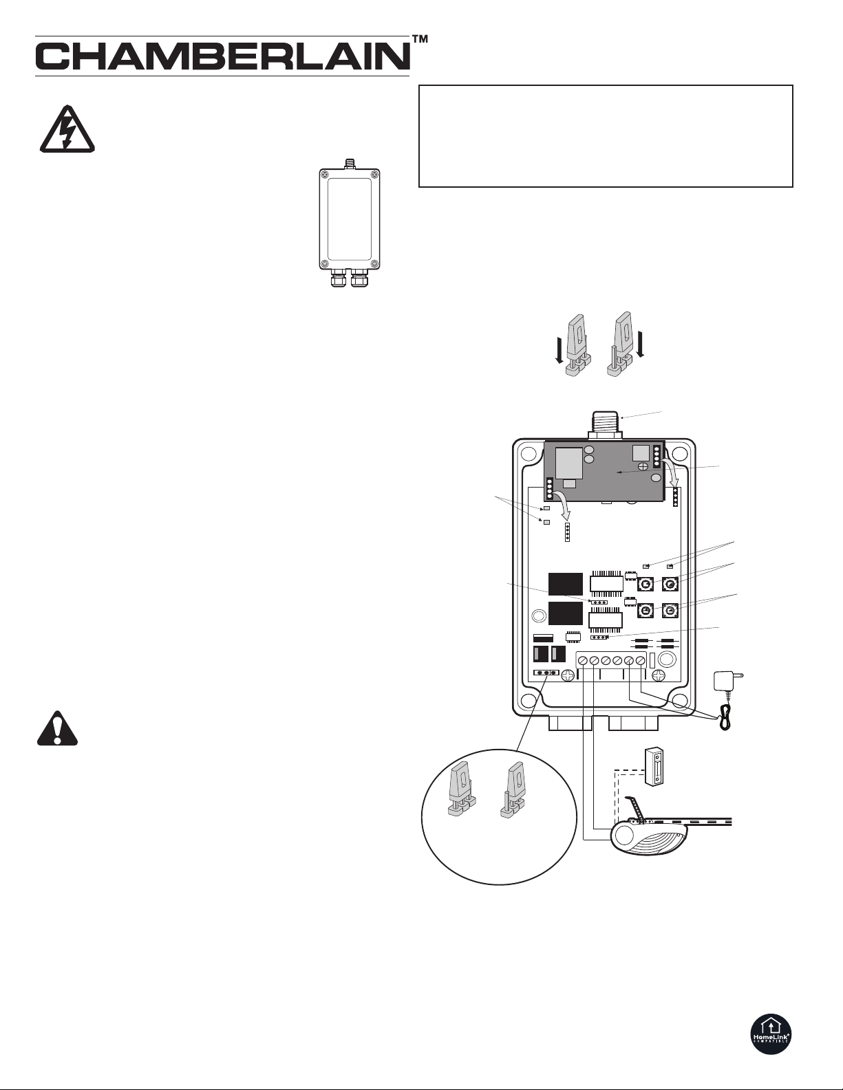
Ant.
OUT A OUT B
I
nput
A
C / DC
LearnA
LearnB
Test
Test
A
B
L
DS2
L
DS1
LDS3
LDS4
Jumper
Kanal A
Programmiertasten
(Kanal A & B )
Befehlstasten
(Kanal A & B)
Kontroll LEDs
(Kanal A & B)
Kontroll LEDs
Schaltzustand
(Kurz - oder Konstantsignal)
Jumper
Kanal B
Antennenanschluss
< 24V
9-16V AC, @ 30mA
9-24V DC, @ 30mA
> 24V
16-30V AC, @ 30mA
24-30V DC, @ 30mA
>24V< 24V
Transformator
CN2
CN1
optional
Empfängers die Netzspannung zum
Torantrieb.
Arbeitet mit folgenden Funkmodulen:
Um die Steuerung mittels Funk zu betreiben, muß
vorher ein Funkmodul auf den Steckplätzen CN1
und CN2 installiert werden.
• 801221 Superheterodyne, 433,92MHz
• 801344 Superregenerativ, 418MHz
Der Universal 2-Kanal Empfänger 8002E kann bis
zu 15 Codes pro Kanal speichern.
INSTALLATION
Der Empfänger sollte so weit vorne wie möglich montiert werden,
vorzugsweise 2 Meter über dem Boden oder höher. Wählen Sie eine Stelle
aus, an der genügend Platz für das Öffnen des Deckels und die Antenne zur
Verfügung steht (so weit wie möglich von Metallstrukturen entfernt). Der
Empfänger und die Antenne verwenden Standard TV Koaxialanschlüsse vom
Typ F. Die Antenne wird direkt in den Empfänger eingeschraubt. Zur
Optimierung der Reichweite ist eine zusätzliche, Kabelverlängerung (86LM)
erhältlich.
Der Transformator (Zubehör 23009E) muß in eine Steckdose eingesteckt
werden, die nicht mehr als 2 Meter vom Empfänger entfernt sein darf, damit
das Kabel mit den Empfänger-Verbindungsklemmen verbunden werden
kann.
1. Befestigen Sie den Empfänger anhand der markierten Bohrungen, die
sich unter der Abdeckung befinden
2. AC/DC sind die Verbindungsklemmen auf der Platine (siehe
Verbinden Sie das Transformatorkabel mit den Verbindungsklemmen
Ziehen Sie anschließend die Klemmen fest an.
3. Verbinden Sie nun die Antriebssteuerung mit den Klemmen des
Universalempfängers. Schliessen Sie dabei das Kabel der
Wandtasterfunktion des Antriebs an die Verbindungsklemmen (Kanal A)
an. Schliessen Sie die Kabel des zweiten Wandschalters (wenn
Sie zwei Tore zu bedienen haben) an die Verbindungsklemmen (Kanal B)
an. Wenn kein Wandschalter oder Schlüsselschalter vorhanden
ist, sehen Sie bitte in der Bedienungsanleitung Ihres Toröffners nach.
4. Stecken Sie den Transformator ein und schalten Sie den Strom wieder
ein. Sie können die Befehlstaste (Test)
Garagentorantriebes/Ihrer Garagentorantriebe verwenden.
1. Drücken Sie den Fernbedienungsknopf; lassen Sie ihn nicht los.
Die Programmiertaste
2.
PROGRAMMIEREN DES EMPFÄNGERS
Betätigen Sie den Torantrieb nur, wenn Sie das Tor voll im
Blickfeld haben, sich dort keine Hindernisse befinden, und
der Antrieb richtig justiert ist. Niemand darf sich im
Schwenkbereich des Tores aufhalten. Lassen Sie Kinder nicht
die Drucktasten oder die Fernbedienung benutzen und auch
nicht in Tornähe spielen.
(Learn) für Kanal A an der Antriebsbedienungstafel
drücken und loslassen. Die Kontroll LED blinkt einmal auf.
3. Lassen Sie nun den Fernbedienungsknopf los.
zum Bedienen Ihres
Der Antrieb funktioniert jetzt, wenn der Fernbedienungsknopf gedrückt wird.
Wenn Sie den Fernbedienungsknopf loslassen, bevor die Kontroll LED
aufblinkt, akzeptiert der Antrieb den Code nicht.
Wiederholen Sie die Schritte 1
–
3, um den Empfänger auf alle
Fernbedienungen, die für dieses Tor in Gebrauch sind, zu programmieren.
Wenn Sie ein zweites Tor in Gebrauch haben, wählen Sie einen anderen
Fernbedienungsknopf und wiederholen die oben beschriebenen Schritte für
Kanal B.
Befestigen Sie den Deckel wieder mit den Schrauben.
So können Sie alle Codes löschen: Halten Sie die Programmiertaste
(Learn) des Empfängers gedrückt, bis die Kontroll LED erlischt (nach
6 Sekunden). Alle vom Empfänger gelernten Codes werden daraufhin
gelöscht.
114A2460C-D
E
Darstellung).
mpfänger
.
Universal 2-Kanal Empfänger
Modell 8002E
TECHNISCHE DATEN
Schaltkontakt.......................................I max. = 5 A; V max. = 30V AC/DC
Versorgungsspannung <24V ....................................9-16V AC, @ 30 mA
...................................................................................9-24V DC, @ 30 mA
...............................................................................24-30V DC, @ 30 mA
Sende-Frequenz......................................................418MHz, 433,92MHz
Der Empfänger kann entweder auf konstantes oder kurzes Schließen der
Ausgangskontakte für beide Kanäle eingestellt werden (A und B).
(Konstantes Schließen wird nur benutzt, wenn dauerhafte Kraft zum
Schließen benötigt wird). Wenn die Brücke in der Position “1” (Kurzsignal)
ist, schließen sich die Kontakte unabhängig von der Länge der
Funkübertragung 150ms lang. Wenn die Brücke in der Position “2”
(Konstantsignal) ist, bleiben die Kontakte während der Funkübertragung
geschlossen. Der Empfänger ist ab Werk auf die Position “1” eingestellt.
Kurzsignal
>24V ..................................16-30V AC, @ 30 mA
EINSTELLEN DER SCHALTZEIT
Konstantes Signal
(Totmann)
Page 2
Universal 2 Channel Receiver
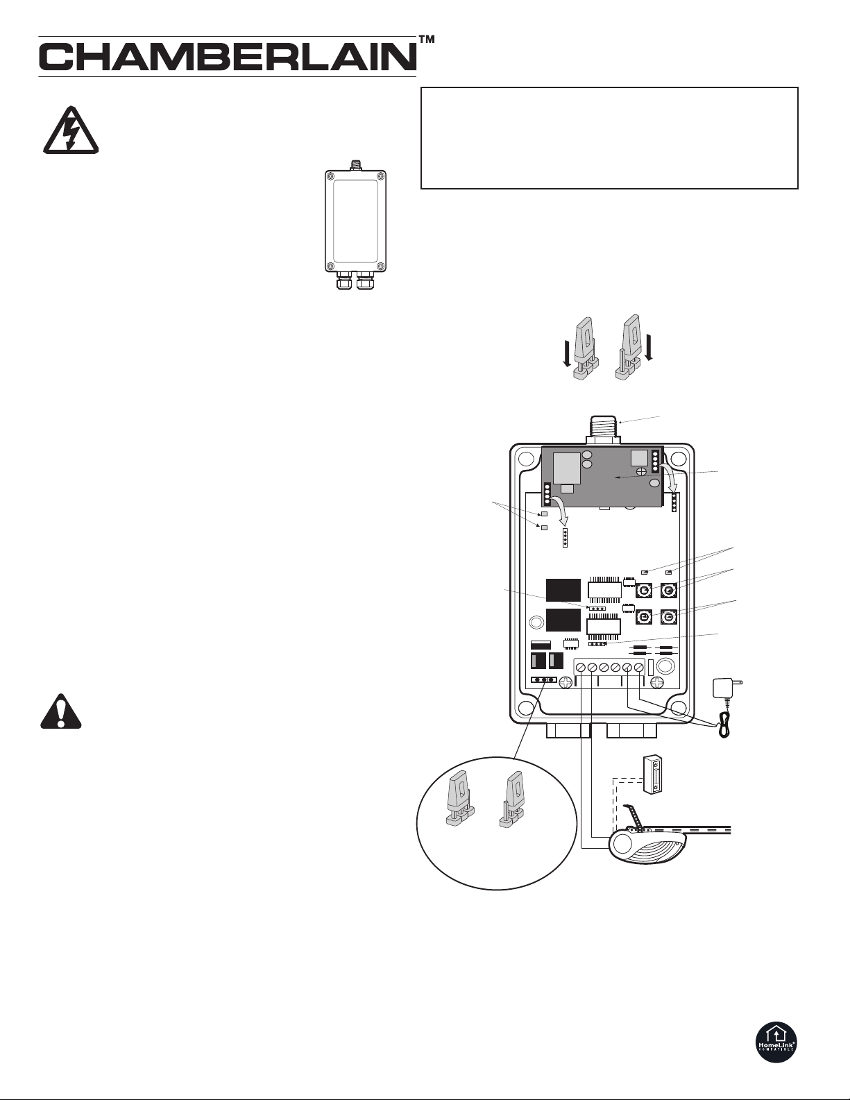
Ant.
OUT A OUT B
Input
AC / DC
LearnA
LearnB
Test
Test
A
B
L
DS2
L
DS1
L
DS3
L
DS4
Jumper
Channel A
Program buttons
(Channel A & B )
Command buttons
(Channel A & B)
Indicator lights
(Channel A & B)
Jumper
Channel B
Antenna Connection
< 24V
9-16V AC, @ 30mA
9-24V DC, @ 30mA
> 24V
16-30V AC, @ 30mA
24-30V DC, @ 30mA
>24V< 24V
Transformer
CN2
CN1
optional
Indicator lights
(momentary or constant)
Model 8002E
DISCONNECT POWER TO GARAGE
DOOR OPENER BEFORE INSTALLING
RECEIVER.
For use with the following RF modules:
To operate the control board via radio, a radio module
must first be installed in slots CN1/CN2.
• 801221 Superheterodyne, 433.92MHz
• 801344 Superregenerative, 418MHz
The 2 Channel Universal Receiver Model 8002E can
be programmed to receive up to 15 codes for each
channel.
INSTALLATION
The receiver should be mounted towards the front of the garage, preferably
about two meters above the floor. Select a location which allows clearance
for opening the cover, and space for the antenna (as far from metal
structures as possible). The receiver and antenna use TV Type F coaxial
connectors. The antenna is threaded directly onto the receiver. An additional
cable extension (86LM) is available to improve the range
The transformer (Model 23009E) must be plugged into the wall within two
meters of the receiver, to allow the wire to reach the receiver terminals.
1. Fasten the receiver securely with screws through the corner holes which
are located under the cover.
2. AC/DC are the terminals on the circuit board. (see illustration)
Connect the transformer wire to the terminals.Now tighten
terminals.
3. Connect operator control board to the terminals of the Universal
Receiver. In this process, connect the cable of te wall-button to terminals
(Channel A). Connect the cable of the second wall-button ( if you have to
operate 2 doors) to the terminals . (Channel B). In case there is no wallbutton or keyswitch, consult the manual of your garage door opener.
4. Plug in the transformer and reconnect power. You may use the
Test button to operate your opener(s).
Receiver
Output Rating ......................................I max. = 5 A; V max. = 30V AC/DC
SPECIFICATIONS
Power input <24V .................................................9-16V AC, @ 30 mA
...................................................................................9-24V DC, @ 30 mA
.................................................................................16-30V AC, @ 30 mA
>24V ................................................24-30V DC,@ 30 mA
RF Frequency...........................................................418MHz, 433.92MHz
TO SET OUTPUT DURATION
The receiver can be set for either constant or momentary closure on the
output contacts for each channel (A and B). (Use constant closure only if
constant pressure is needed.) With the jumper in “1” (Momentary) position,
the contacts will close for 150ms regardless of the length of radio
transmission. With the jumper in “2” (Constant) position, the contacts will
stay closed as long as the radio continues transmitting.
Momentary
Constant signal
(Hold to run)
PROGRAMMING THE RECEIVER TO ACCEPT
YOUR TRANSMITTER CODE
1.
2. Press and release the Learn button in the Control Center on the opener
3.
Now the opener will operate when the remote control push button is
pressed.
Activate the opener only when door is in full view, free of
obstruction and properly adjusted. No one should enter or
leave garage while door is in motion. Do not allow children to
operate push button(s) or remote(s). Do not allow children to
play near the door.
Press and
panel. The indicator light will flash once.
hold the
remote control push button.
Release the remote push button.
If you release the remote control push button before the indicator
lights flash, the opener will not accept the code.
Repeat steps
3 to program the receiver for all remote controls in use for
–
1
that door. If a second door is in use, use a different remote control button
and repeat the steps for channel B.
Replace top cover with mounting screws.
To erase all codes from the receiver: hold the receiver’s Learn button until
the indicator light goes off (after 6 seconds). All codes that the receiver has
learned will be erased.
114A2460C-GB
Page 3

Ant.
OUT A OUT B
Input
AC / DC
LearnA
LearnB
Test
Test
A
B
LDS2
L
DS1
LDS3
L
DS4
Connecteur antenne
< 24V
9-16V AC, @ 30mA
9-24V DC, @ 30mA
> 24V
16-30V AC, @ 30mA
24-30V DC, @ 30mA
>24V< 24V
Transformateur
CN2
CN1
M
odule radio
en option
Diodes de contrôle
(Canal A&B)
Boutons de
programmation
(Canal A&B)
Boutons de commande test
(Canal A&B)
Cavalier Signal
Canal A
Cavalier Signal
Canal B
Diodes de contrôle
Temps de réponse
du signal
(Signal bref ou constant)
METTEZ LA MOTORISATION HORS
TENSION AVANT D'INSTALLER LE
RÉCEPTEUR UNIVERSEL.
Fonctionne avec les modules radio suivants:
Embrochez le module radio sur les broches CN1 et CN2.
• 801221 Superhétérodyne, 433,92MHz
• 801504 Superréactif, 433,92MHz
Le récepteur universel 2 canaux, modèle 8002E peut être
programmé pour recevoir jusqu'à 15 codes pour chaque
canal.
INSTALLATION
Le récepteur doit être monté le plus près possible de la porte de garage ou du
portail de préférence à environ deux mètres du sol. Choisissez un
emplacement qui permette un accès facile pour ouvrir le couvercle, et assez
d'espace pour l'antenne (aussi loin que possible de tout élément métallique).
Le récepteur et l'antenne sont dotés de connecteurs coaxiaux TV type F.
L'antenne est directement vissée sur le récepteur. Pour améliorer la portée
radio du récepteur, un kit de rallonge d’antenne (86LM) est disponible en
option pour déporter l’antenne.
Le transformateur (modèle 23009E) doit être branché dans une prise située
à 2 mètres maximum du récepteur afin de pouvoir le raccorder aux bornes
du récepteur.
1. Fixez solidement le récepteur à l'aide de trous situés sous le couvercle.
2. Les bornes de raccordement du transformateur sont indiquées AC/DC sur le
circuit imprimé (voir schéma ci-contre). Branchez sur ces bornes les câbles du
transformateur.
3. Raccordez ensuite la platine de commande de la motorisation aux bornes du
récepteur. Pour cela, raccordez le câble des bornes de connexion du boutonpoussoir ou contacteur à clé (contact sec) aux bornes OUT A du récepteur
(canal A). Si vous souhaitez commander deux automatismes à l’aide du
même récepteur universel, raccordez le câble des bornes de connexion du
deuxième bouton-poussoir ou contacteur à clé aux bornes OUT B du
récepteur (canal B). Si vous ne disposez ni d’un bouton-poussoir, ni d’un
contacteur à clé, reportez vous à la notice technique de votre motorisation
pour effectuer les branchements.
4. Branchez le transformateur et remettez le courant. Il est conseillé d'utiliser
le/les bouton/s Test pour commander votre/vos automatisme/s.
1. Appuyez sur le bouton de la télécommande et maintenez le bouton
Faites fonctionner l’automatisme uniquement lorsqu’il est
ajusté correctement, que vous voyez la porte / le portail
entièrement et aucun obstacle se trouve dans le champ de
manoeuvre de la porte. Personne ne doit entrer ni sortir du
garage lorsque la porte est en mouvement. Ne laissez pas les
enfants utiliser le(s) bouton(s)-poussoir ni la/les
télécommandes(s). Ne laissez pas les enfants jouer à
proximité dela porte.
pressé.
PROGRAMMATION DU RÉCEPTEUR UNIVERSEL
2. Appuyez sur le bouton de programmation du canal A LearnA et relâchez. La
diode de contrôle (LED) s'allume et s'éteint aussitôt.
3. Relâchez ensuite le bouton de la télécommande.
A présent, l'automatisme fonctionnera chaque fois que vous appuierez sur le
bouton de la télécommande.
Si vous relâchez le bouton de la télécommande avant que la diode de
contrôle n’ait clignoté, l’automatisme n’enregistrera pas ce code.
Répétez les étapes 1 à 3 pour programmer le récepteur sur toutes les
télécommandes utilisées pour cette porte. Si vous disposez d’un deuxième
automatisme piloté par le même récepteur universel, utilisez un bouton différent
de la télécommande et répétez les étapes 1 à 3 pour le canal B.
Remettez le couvercle en le vissant.
Pour effacer tous les codes du récepteur: maintenez appuyé le bouton
LearnA ou LearnB (en fonction du canal sur lequel ont été programmées les
télécommandes) du récepteur jusqu'à ce que la diode de contrôle
correspondante s'éteigne (après env. 6 secondes). Tous les codes enregistrés
par le récepteur seront alors effacés.
Recepteur
Récepteur Universel 2 canaux
Modèle 8002E
SPÉCIFICATIONS
Contact de commutation .....................I max. = 5 A; V max. = 30V AC/DC
Tension d’alimentation <24V ...................................9-16V AC, @ 30 mA
...................................................................................9-24V DC, @ 30 mA
.................................................................................24-30V DC, @ 30 mA
Fréquence radio........................................................418MHz, 433,92MHz
RÉGLAGE DU TEMPS DE RÉPONSE DU SIGNAL
Le récepteur peut être réglé pour une fermeture constante ou brève des
contacts de sortie pour chacun des canaux A et B. (N’utilisez le signal
constant que si vous avez besoin d'une force constante de fermeture.) Si le
cavalier est en position "1" (signal bref), les contacts de sortie se fermeront
pendant 150ms indépendamment de la durée d’émission du signal radio. Si
le cavalier est en position "2" (signal constant), les contacts resteront fermés
tant que le signal radio sera émis (manoeuvre par contact maintenu;
fonctionnement homme-mort). Le récepteur est réglé en position 1 à sa
sortie d'usine.
Position 1:
Signal bref
>24V .................................16-30V AC, @ 30 mA
Position 2:
Signal constant
(Homme-mort)
114A2460C-F
Page 4

Universele 2-kanaals ontvanger
Ant.
OUT A OUT B
I
nput
A
C / DC
LearnA
LearnB
Test
Test
A
B
LDS2
LDS1
L
DS3
LDS4
Jumper
Kanaal A
P
rogrammeerknoppen
(Kanaal A & B )
Bedieningsknoppen
(Kanaal A & B)
Controle LEDs
(Kanaal A & B)
Jumper
Kanaal B
Antenneaansluiting
< 24V
9-16V AC, @ 30mA
9-24V DC, @ 30mA
> 24V
16-30V AC, @ 30mA
24-30V DC, @ 30mA
>24V< 24V
Transformator
CN2
CN1
optioneel
Controle LEDs
(impuls of dodeman)
type 8002E
VOOR MONTAGE VAN DE ONTVANGER
DIENT DE STROOMVOORZIENING VAN
DE GARAGEDEUROPENER TE
WORDEN UITGESCHAKELD.
Werkt met de volgende zendmodules:
Om de besturing via een radiografisch signal te kunnen
gebruiken, moet er eerst een radiomodule op de
insteekplaatsen CN1/CN2 worden geinstalleerd
• 801221 Superheterodyne, 433,92MHz
• 801344 Superregeneratief, 418MHz
De universele 2-kanaals ontvanger 8002E kan per kanaal
15 codes opslaan.
ntvanger
INSTALLATIE
De ontvanger moet voorin de garage worden gemonteerd, bij voorkeur 2
meter boven de grond. Kies de plaats zo dat er ruimte is om het deksel te
openen. Bovendien moet er plaats zijn voor de antenne (zo ver mogelijk
verwijderd van metalen objecten). De ontvanger en de antenne maken
gebruik van TV-coaxiaalaansluitingen van het type F. De antenne wordt
rechtstreeks op de ontvanger gemonteerd. Voor optimering van het
ontvangsbereik is een optionele kabelverlenging (86LM) te bestellen.
De transformator (Accessoire 23009E) moet in een stopcontact op minder
dan 2 meter afstand van de ontvanger worden gestoken, zodat de kabel met
de aansluitklemmen van de ontvanger kan worden verbonden.
1. Bevestig de ontvanger door middel van schroeven door 2 van de 4 gaten
in de hoeken onder het deksel.
2. AC/DC zijn de aansluitklemmen op de printplaat (zie afbeelding). Sluit de
draden van de transformator op deze klemmen aan. Draai vervolgens de
klemmen stevig vast.
3. Sluit U nu uw motorbesturing aan op de universele ontvanger, door de
verkabeling van de drukknop functie (op motorprint) met de
aansluitklemmen van kanaal A op de de universele ontvanger te
verbinden. Als U twéé motoren op deze universele ontvanger aan wilt
sluiten, herhaald U de voorgaande stap, maar gebruik voor de tweede
motor de aansluiting kanaal B. Als géén aansluiting voor een drukknop of
sleutelschakelaar voorhanden is, kijkt U in de gebruiksaanwijzing van uw
garagedeuropener na.
4. Steek de transformator in het stopcontact en schakel de
stroomvoorziening weer in. Met de bedieningsknop (Test) kunt u de
garagedeuropener(s) bedienen.
PROGRAMMEREN VAN DE ONTVANGER
Stel de opener alleen in werking wanneer de deur volledig in
het zicht is, vrij van obstakels en goed afgesteld. Laat
niemand onder de garagedeur door lopen wanneer deze in
beweging is. Laat kinderen niet aan de bedieningsknop(pen)
of afstandsbediening(en) komen en niet in de buurt van de
deur spelen.
Druk op de afstandsbedieningsknop; laat deze niet los.
1.
2. De programmeertoets (Learn) voor kanaal A bij het bedieningspaneel van
de aandrijving indrukken en loslaten. De controle-LED knippert eenmaal.
3. Laat nu de afstandsbedieningsknop los.
De opener werkt nu wanneer de afstandsbedieningsknop wordt ingedrukt.
Wanneer u de afstandsbedieningsknop loslaat voordat de controleLED gaat knipperen, accepteert de aandrijving de code niet.
Herhaal de handelingen 1-3 om de ontvanger te programmeren voor alle
zenders die voor deze deur worden gebruikt. Als u een tweede deur in
gebruik heeft, kiest u een andere zenderknop en herhaalt u de hierboven
beschreven handelingen voor kanaal B.
Schroef het deksel weer op zijn plaats.
U kunt alle codes als volgt wissen: houd de programmeerknop (Learn)
van de ontvanger ingedrukt tot het controlelampje uitgaat (na 6 seconden).
Alle codes die de ontvanger heeft geleerd, worden hierdoor gewist.
114A2460C-NL All Rights Reserved
O
© 2006, Chamberlain GmbH
TECHNISCHE GEGEVENS
Schakelcontact....................................I max. = 5 A; V max. = 30V AC/DC
Voedingsspanning <24V..........................................9-16V AC, @ 30 mA
...................................................................................9-24V DC, @ 30 mA
>24V .......................................16-30V AC, @ 30 mA
.................................................................................24-30V DC, @ 30 mA
Zendfrequentie..........................................................418MHz, 433,92MHz
INSTELLEN VAN DE SCHAKELTIJD
De ontvanger kan worden ingesteld op blijvend of kortstondig sluiten van de
uitgangscontacten van beide kanalen (A en B jumper). (Blijvend sluiten
wordt alleen gebruikt als permanente aandrijving is vereist voor het sluiten
van de deur). Met het brugcontact in positie 1 (impuls) worden de contacten
gedurende 150 ms gesloten, ongeacht de duur van het zenden.
Met het brugcontact in positie 2 (dodeman) blijven de contacten tijdens de
gehele zendduur gesloten.
Impuls
DECLARATION OF CONFORMITY
Universal 2 Channel Radio Receiver
is in conformity to the applicable sections of Standards
BAPT 222 ZV 125, per the provisions & all amendments of the EU Directives
Universal 2 Channel Radio Receiver Model No. 8002E, when installed and maintained according
to all the Manufacturer’s instructions in combination with a Garage Door Opener and Garage
Door, which have also been installed and maintained according to all the Manufacturer’s
instructions, meets the provisions of EU Directive 89/392/EEC and all amendments.
I, the undersigned, hereby declare that the equipment specified above and any accessory listed
Chamberlain GmbH
D-66793 Saarwellingen
June, 2005
....................................................................Model No. 8002E
ECLARATION OF INCORPORATION
D
in the manual conforms to the above Directives and Standards.
Dodeman
..................... ETS 300 683, ETS 300 220,
B. P. Kelkhoff, Manager, Regulatory Affairs
............89/336/EEC
 Loading...