

Page 1
Model 78LM
Multi-Function Door Control
OWNERS INSTRUCTIONS
© 2000, The Chamberlain Group, Inc.
114A2380C All Rights Reserved Printed in Mexico
DO NOT CONNECT TO LIVE ELECTRICAL WIRING.
CONNECT ONLY TO 24 VOLT LOW VOLTAGE WIRES.
CONNECTION TO LIVE WIRES OR HIGHER VOLTAGE MAY
CAUSE SERIOUS INJURY FROM SHOCK, BURN OR
ELECTROCUTION.
Children operating or playing with a garage door opener
can injure themselves or others.
The garage door could
close and cause serious injury or death.
Install the door control (or any additional push buttons) out
of the reach of children and away from all moving parts of
the door and door hardware,
but where the garage door is
visible.
Do not allow children to operate the push button(s)
or the remote control transmitter(s).
A moving garage door could injure someone under it.
Activate the opener only when the door is properly
adjusted, you can see it clearly, and there are no
obstructions to door travel.
STANDARD
WALL MOUNT
For use with garage door openers manufactured after
January 1, 1995. To ensure proper functioning of your opener,
remove all old or previous push buttons/wall control panels.
Use only the enclosed door control for proper operation.
Locate the door control within sight of the door at a minimum
height of 5 feet where small children cannot reach, and away
from all moving parts of the door and door hardware.
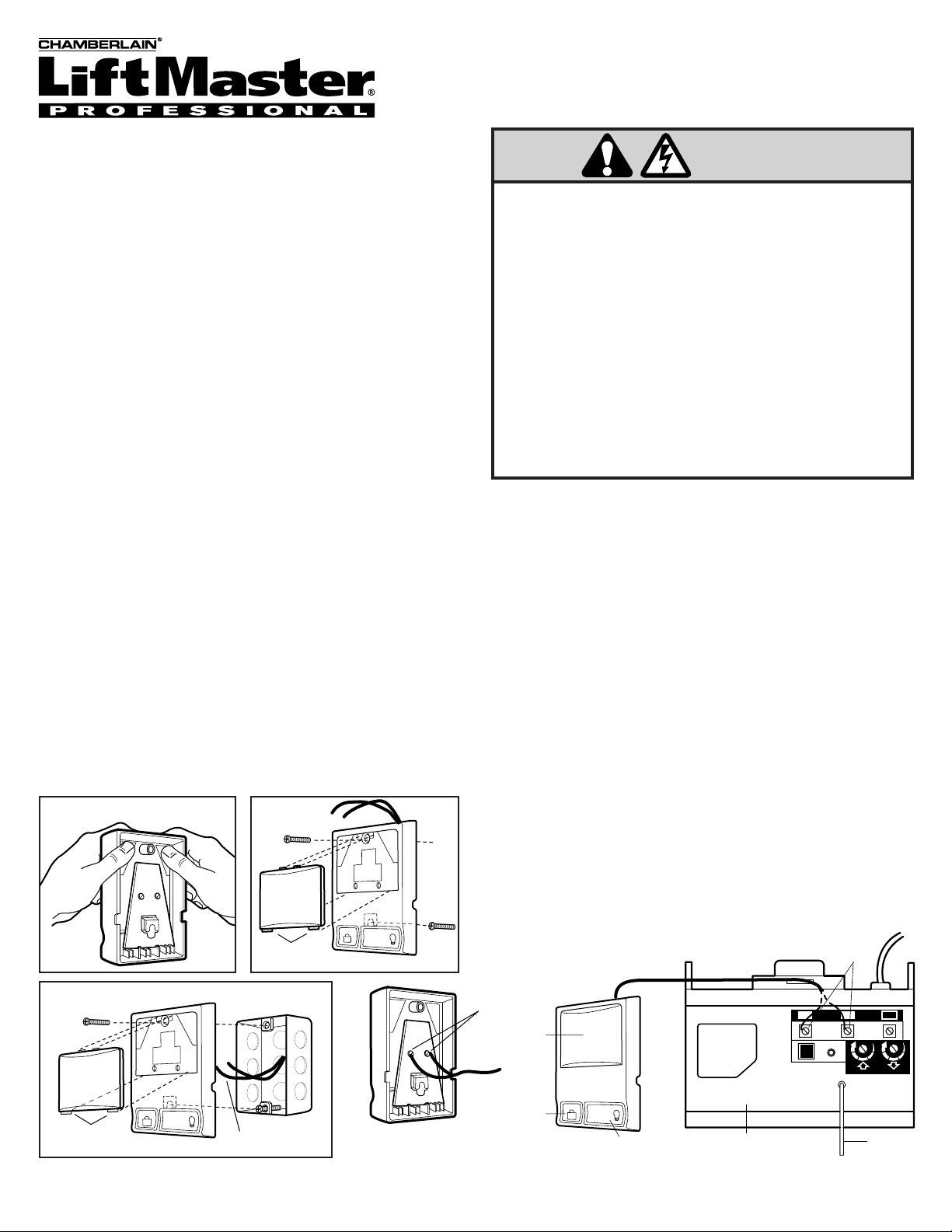
INSTALLATION
The multi-function door control is typically attached directly to the
wall. For pre-wired installations (as in new home construction) it can
be mounted to a standard single gang box. See illustrations.
• Strip 1/4" of insulation from one end of the bell wire. Connect the
wire to the two screw terminals on the back of the door control as
follows: white wire to 2 and white/red wire to 1.
(NOTE: After
installation, a green indicator light behind the white translucent
cover will indicate proper connection. If not lit, the Lock and Light
features will not function (reverse wires to correct).
• Before mounting, remove the white cover by gently pushing both
thumbs against the upper corners of the cover on the
back side
of
the door control (see illustration).
•
For standard wall mount,
mark the wall about 1-1/4" up the
centerline from the bottom of the door control. Install a 6ABx1-1/4"
self-tapping screw at this point, allowing about 1/8" to protrude from
the wall. Slip the lower part of the door control over the screw head
and adjust for snug fit. Drill and install the top screw with care to
avoid cracking the plastic housing.
Do not overtighten.
Run the bell
wire up the wall and across the ceiling to the opener. Use insulated
staples to secure the wire in several places. Be careful not to
pierce the wire with a staple, creating a short.
•
For pre-wired installations,
partially install a 6-32x1" machine
screw into the bottom of the gang box, allowing about 1/8" to
protrude. Slip the lower part of the door control over the screw
head and adjust for snug fit. Install top screw with care to avoid
cracking plastic housing.
Do not overtighten.
• Connect the bell wire to the opener terminal screws as follows:
white to 2 and white/red to 1.
• After testing, replace the cover by inserting bottom tabs and
snapping into place. To remove the cover after mounting, gently
pry at the top with a paper clip or small flat head screwdriver.
OPERATING THE DOOR CONTROL
The Door Control Push Button: Press the white square to open or
close the door. Press again to reverse the door during the closing
cycle or to stop the door while it's opening.
Light Feature: Press the Light button to turn the opener light on or
off. If you turn it on and then activate the opener, the light will remain
on for 4-1/2 minutes. Press again to turn it off sooner. The Light
button will not control the opener lights when the door is in motion.
Lock Feature: Designed to prevent operation of the door from
portable remote controls. However, the door will open and close
from the Door Control push button and from the Keylock and the
Keyless Entry Accessories.
To activate:
Press and hold the Lock button for 2 seconds. The
push button indicator light will flash as long as the lock is on.
To turn off:
Press and hold the Lock button again for 2 seconds.
The indicator light will stop flashing. Normal operation will resume.
The Lock feature will also turn off whenever the Smart button on the
opener end panel is activated.
REMOVE COVER
FOR SERVICE DIAL OUR TOLL FREE NUMBER:
1-800-528-2817
WARNING
WHT
RED
1
2
LOCK
To Replace,
Insert Bottom Tabs First
PRE-WIRED INSTALLATION
LOCK
To Replace,
Insert Bottom Tabs First
LIGHT
24 Volt
2-Conductor Bell Wire
LIGHT
Multi-Function
Door Control Panel
Terminal Screws
Door Control
Push Bar
WHT
RED
1
2
2-Conductor
Bell Wire
Lock
Button
Opener Terminal Screws
1
LOCK
LIGHT
Light Button
3
2
9
9
1
7
7
3
5
5
KG
KG
AntennaOpener Panel
1
3
 Loading...