


CV-900
CV-900 / CV-1800 / CV-2800
HEAVY DUTY PROFESSIONAL AMPLIFIERS
USER MANUAL
IMPORTANT SAFETY INSTRUCTIONS
1. Read Instructions – All the safety and operating instructions should be read before
this product is operated.
2. Retain Instructions – The safety and operating instructions should be retained for
future reference.
3. Heed Warnings – All warnings on the appliance and in the operating instructions
should be adhered to.
4. Follow Instructions – All operating and use instructions should be followed.
5. Do not use this amplifier near water. The amplifier should not be used near water
or moisture or dripping or splashing — for example, in a wet basement, in the
rain, or near a swimming pool. Objects that contain liquids, such as vases, shall
not be placed on the ampllifier.
6. Clean only with dry cloth.
7. Do not block any ventilation openings. Pleaase install in a well ventilated
environment.
8. Do not install near any heat sources such as radiators, heat registers, stoves, or
other apparatus (including amplifiers) that produce heat.
9. Do not defeat the safety purpose of the polarized or gounding plug. Apolorized
plug has two lnades with one wider than the other. A grounding plug has two
blades and third prong. The wide blasde or the third prong is provided for safety.
If the provided plug does not fit into your outllet, consult an electician for
replacement of the obsolete outlet.
10. WARNING: The mains plug or amplifier power inlet is used as a disconnet
device, the disconnect device shall remain readily operable. Protect the power
cord from being walkied on or pinched particularly at theplugs, conenience
receptacles, and at the point where they exit from the amplifier.
11. Use only attachments/accessories specified by the manufacturer.
1
2. Use this amplifier only withcarts and rack equipment rated
for this type of equipment. When a cart or rack is used use
caution when moving to avoid injury from a tip-over.
13. Unplug the amplifier during lightening storms or when
unused for longperiods of time.
14. Refer all servicing to qualified personnel. Servicing is required when the
amplifier has been damaged in any way, such as the power cord is damaged,
objects have fallen into the amplifier, the amplifier has been exposed to rain or
moisture, has been dropped or does not operate normally.
16.This amplifier should only be operated from the type of power source indicated
on the rating label. If you are not sure of the type of power coming from your wall
socket, consult your product dealer or local power company.
!7. WARNING: to prevent hazardous electrical shcok do not touch the conductive
parts of the out put terminals. The external wiring connected to these terminals
requires installation by a qualified technician.
18. This product is in compliance with EU WEEEE regulations.
Disposal of end of life of product shoud not be treated as
municipal waste. Please refer to your local regulations for
i
nstructions on proper disposal of this product.
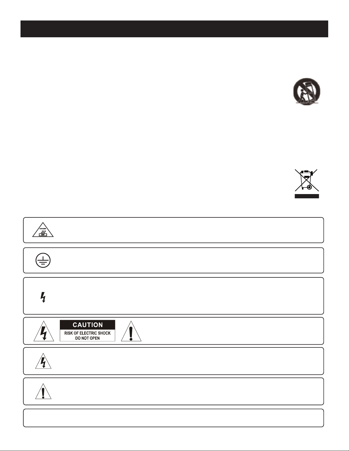
CAUTION: To reduce the risk of electric shock, do not remove any
cover. No user-serviceable parts inside. Refer servicing to
qualified service personnel only.
The lightning flash with arrowhead symbol within the equilateral triangle is intended to alert the user
to the presence of un-insulated “dangerous voltage” within the product’s enclosure that may be of
sufficient magnitude to constitute a risk of electric shock.
The exclamation point within the equilateral triangle is intended to alert the user to the presence of
important operation and maintenance (servicing) instructions in the literature accompanying this
appliance.
CAUTION: To prevent electric shock, do not use this polarized plug with an extension cord, receptacle or other
outlet unless the blades can be fully inserted to prevent blade exposure.
"Protective earthing terminal.The amplifier should be connected to a mains socket outlet with a
protective grounding connection terminal. The amplifier should be connected to a mains socket
outlet with a proper gounding connection for safe operation.
Caution Hot Surface! Heat danger. Please don’t touch the area because a high temperature
danger may exist. Use caution when touching surfaces makred with this logo as they may become
hot during extend use.
This lightening flash is intended to alert the user to the presense of non-insulated “dangerous
voltage” on the output terminals that may be of sufficent magnitude to constitute a risk of electric
shock. The external wiring connected to the terminals requires installation by an instructed person or
the used of ready -made leads or cords. of

INTRODUCTION
Thank you for your decision to purchase Cerwin-vega’s innovative new CV Series professional power amplifier! Engineered for superior
sound reproduction, the CV Series line of professional amplifiers deliver top quality audio at an affordable price. The CV Series offer a standard of reliability and efficiency that makes them the perfect solution for every DJ, musician, and sound engineer. Welcome to a new level
of professional quality sound performance!
UNPACKING & INSTALLATION
Although it is neither complicated to install, nor difficult to operate your amplifier, a few minutes of your time are required to read this manual for a properly wired installation, and to become familiar with the unit’s features. Please take great care in unpacking the unit and do
not discard the carton and other packing materials. They may be needed when moving the unit and are required if it ever becomes necessary to return the unit for service. Never place the unit near a radiator, in front of heating vents, in direct sunlight, in excessive humidity, or dusty locations to avoid damages and to guaranty a long reliable use. Connect the unit with the system components according to
the description on the following pages.
FEATURES
• Cerwin-vega amplifiers deliver the following power ratings.
• CV-900 - 2 x 210 Watts at 8 ohm, 2 x 320 Watts at 4 ohm and 2 x 420 Watts at 2 ohm
• CV-1800 - 2 x 400 Watts at 8 ohm, 2 x 600 Watts at 4 ohm and 2 x 900 Watts at 2 ohm
• CV-2800 - 2 x 600 Watts at 8 ohm, 2 x 900 Watts at 4 ohm and 2 x 1400 Watts at 2 ohm
• 2-channel, parallel or bridged mono operating modes for flexible application 900 Watts for CV-900, 1800 Watts for CV-1800 and 2800
Watts for CV-2800
• Independent limiters for each channel reduce overload distortion
• Independent input level controls for each channel allow precision adjustments
• Precise signal and clip LED indicators to monitor performance, allow you to correct for overloading (clipping) condition
• Low-frequency filters (40 Hz) remove rumble and subsonic frequencies
• Twin-tunnel and two temperature-sensitivity forced-air cooling system to maintain a low operating temperature during use
• Balanced XLR or balanced 1/4-inch TRS Combination input connector for each channel and LINK ports
• 5-way output binding posts or Speakon® connectors enable secure operation
• High-current toroidal transformer for absolute reliability
• Independent DC and thermal overload protection on each channel automatically protects amplifier and speaker from damage or failure
• The CV-Series can be mounted in any standard 19” rack
3
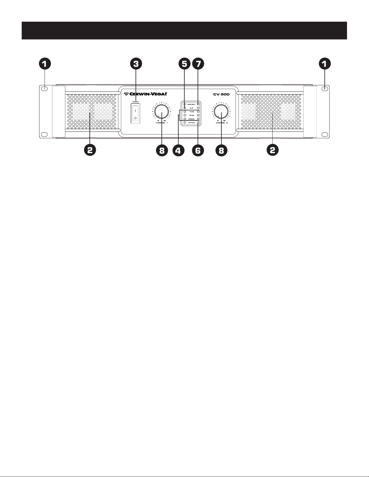
FRONT PANEL CONTROLS
1. Rack Ears
These ears are used to mount the amplifier in any standard 19”
rack.
2. Fan Vent
The CV-Series amplifiers are cooled by two rear-mounted fans (except for CV-900 which is cooled by a single rear mounted fan).
Cool air flows through the front fan filters, reducing the
temperature of internal components while forcing the heat out the
rear vents. Never block these vents and keep them clean at all
time.
3. AC Power Switch
This switch powers the unit on and off.
4. Signal Indicators
These blue LED's will illuminate to indicate that a signal is
present at the amplifier input, and that the signal is being amplified.
5. Clip Indicators
These red LED's will illuminate at the clipping threshold. These
lights should not light up during normal use as they indicate
signal outside of the amplification range of the amplifier. When a
signal is "clipped" and the clip indicator illuminates, it means that
the signal is being distorted at the output stage. Prolonged
clipping can not only damage your amplifier, but also your
speakers, so be careful to monitor the clip indicator during setup
and use. If the clip indicator is illuminated then simply lower the
channel gain or input signal until the indicator does not light.
These blue LED's indicate that AC power is connected and the amplifier is turned on.
7. Protect Indicators
These red LED's indicate that the channel is in Protect mode.
When the channel goes into protect mode all output for that
channel will be muted. The protect LED's light when overheating or
other severe problems occur. This is to protect any speakers connected to the channel. The LED's also light for approximately five
seconds whenever the unit is powered on and fade slowly when
the amplifier is powered off.
8. Channel input level control
These two 21-position detented potentiometers adjust input level
for their respective amplifier channels. In Bridged Mono Mode, only
channel 1 level control is used to adjust signal level. In Parallel
Mode, both input level control are used to adjust signal level for
their respective amplifier channels. At their fully
counter-clockwise position, the signal is attenuated by more than
80dB. At their fully clockwise position, the signal is at maximum
gain. When 0 dBu of signal arrives at the input jacks and the Channel input level controls are set to their fully clockwise
position, the unit delivers full power output.
6. Active Indicators
4
 Loading...