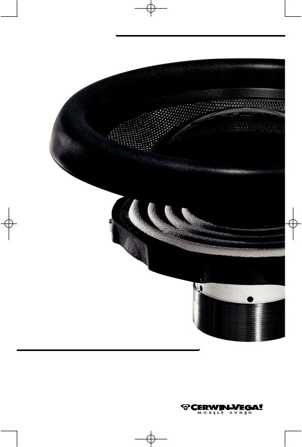
Cerwin Vega Stroker PRO Owners Manual
StrokerproManual bi-langual 9/20/05 9:10 AM Page 1
Recone Manual
Manual De Cambio De Conos
Recone-Handbuch
Manuel De Remplacement De Cône
STROKER
PRO
CERWIN-VEGA! MOBILE AUDIO
S U B W O O F E R
StrokerproManual bi-langual 9/20/05 9:10 AM Page 2
C E R W I N - V E G A ! S T R O K E R P R O R E C O N E M A N U A L
STROKER PRO RECONE INFORMATION
Before you start:
1.Have the recone kit ready for installation – do not leave the speaker gap (disassembled) open for any length of time (like during lunch or to talk with a customer etc.)
2.Ask someone for help moving the speaker and to secure it during reconing process.
3.We recommend that you have Elmer’s white glue and Loctite thread lock 242 (BLUE not RED) for best results.
4.It is VERY important to perform reconing in a clean environment free of dirt and most importantly all metal particles. Do not attempt this in an install bay where metal is cut or filed. The incredibly strong motor on the Stroker Pro Woofers can attract metal particles to the gap area from a few feet away. Metal particles in the gap permanently damage the speaker and will void any warranty.
Recone Steps:
1.Remove Spider Ring bolts (eight), from the bottom side of the basket. Bolts can be removed with included hex wrench. You may need to turn the basket on its side to get access.
2.Place the speaker on its side and remove Aluminum Bias Tower Ring at the center of the backplate. Using the ring tool included with the recone kit, turn the ring counterclockwise until it is completely free of the tower (3/8 drive socket wrench not included).
3.Place the speaker facing up and remove the Edge Clamping Ring. Eight hex bolts clamp the edge to the basket. These are removed using the included wrench.
StrokerproManual bi-langual 9/20/05 9:10 AM Page 1
C E R W I N - V E G A ! S T R O K E R P R O R E C O N E M A N U A L
4.The Moving Parts Assembly (cone / spider / bias tower) can now be removed from the basket. Note that the edge has a small amount of PVA adhesive gluing it to the basket.
Lifting one section of the edge will break this bond and the edge will lift free.
5.Make note of any obvious problems, (voice coil burnt, mechanical marks on the coil, etc.) Discard the old Moving Parts Assembly.
6.Turn the speaker on its side and insert one centering pin into each alignment hole in the backplate of the woofer (total of 6), Make sure pins are inserted completely.
7.Turn the speaker on its magnet facing up and align the pins so that they are all touching the pole and symmetrically arranged.
8.CAREFULLY lower the new Moving Parts Assembly into the basket making sure that all of the pins are inside the voice coil. The assembly should slide smoothly into place with just a small bit of friction between the pins and the voice coil.
9.CAREFULLY turn the speaker on its side. Put a small amount of the Loctite 242 on the thread and thread the Aluminum Bias Tower Ring on to the bias tower tube. Use the ring tool to snugly tighten the ring (25 foot pounds). Too much torque will strip the threads. The Loctite will make sure the ring stays put with a medium amount of tightening force.
StrokerproManual bi-langual 9/20/05 9:10 AM Page 2
C E R W I N - V E G A ! S T R O K E R P R O R E C O N E M A N U A L
10.Return the speaker to its back and thread the Spider Ring bolts through the basket and into the Spider Ring. Make sure to use a small amount of Loctite on the threads. Do not tighten completely. The spider ring should be able to move freely (about 1mm in all directions)
11.Put a small amount of white glue on the basket where the
edge will seat. You will need to lift the edge slightly. It may be easier to use a brush for this application. Only a thin layer is needed. Put a small amount of white glue on the edge of the surround where the clamping ring will seat (The white glue acts as a lubricant during assembly).Move quickly to step 12 before the glue can start to dry.
12.Make sure the edge is seated in the groove in the basket. (It should do this naturally.) Place the edge clamp over the edge and thread each bolt into place. (Make sure to add a small amount of Loctite to each thread.) When each bolt is seated against the clamp make sure that the clamp is parallel to the basket. Turn each bolt 1 turn and then proceed to the opposite bolt on the basket similar to tightening lug nuts on a tire. Continue tightening until all bolts are snug. If they are all seated correctly the gap between the clamp ring and basket should be even on all 4 sides. The gap should be between 0 and .5 mm. Clean any white glue the seeps up from the clamping ring
13.Tighten the bolts on the spider tower following the same procedure on the edge ring until snug. Do not over tighten.
14.Turn the speaker on its side and remove the centering pins.
15.CAREFULLY move the speaker cone in and out and check for any
obvious rubs. Note that it is easy to put too much pressure on one side of the cone and cause a rub, so be careful to apply even pressure. If there is an obvious rub go back to the beginning and start again.
16.Connect the speaker back to your system (install in the box) and adjust it so you can listen to the sub by itself. Start at a very low volume and listen for any mechanical rubbing sounds. Continue to increase volume until you reach the maximum power for your system. If you do not hear mechanical noise, i.e. voice coil rubbing, congratulations! You are done.
17.If you do hear coil rubbing, turn the system off immediately and start the entire process again from the beginning. Inspect the gap carefully for metal particles. If you see any do your best to clean them with masking tape, Fold the masking tape in half lenghtwise and insert into the gap to remove particles . (The glue will hold the metal and allow you to remove it. If you can’t remove all of the particles or if you can not successfully complete the recone call CerwinVega Customer Service.
StrokerproManual bi-langual 9/20/05 9:10 AM Page 3
C E R W I N - V E G A ! S T R O K E R P R O R E C O N E M A N U A L
INFORMACIÓN SOBRE CAMBIO DE CONOS PARA STROKER PRO
Antes de empezar:
1.Tenga listo el kit de cambio de conos para la instalación – no deje el entrehierro del altavoz (desmontado) abierto (por ejemplo, durante el almuerzo o mientras habla con un cliente, etc.)
2.Pida a alguien que le ayude a mover el altavoz y asegúrelo durante el proceso de cambio de conos.
3.Para obtener los mejores resultados, le recomendamos tener goma blanca Elmer’s y compuesto para roscas Loctite 242 (AZUL, no ROJO).
4.Es MUY importante realizar el cambio de conos en un ambiente limpio, sin polvo, y particularmente de partículas metálicas. No intente realizar esta operación en un banco de instalación donde se corte o se lime metal. El increíblemente fuerte motor de los woofers Stroker Pro puede atraer partículas metálicas al área del entrehierro desde una distancia de varios pies. Las partículas metálicas en el entrehierro dañarán permanentemente el altavoz y anularán la garantía.
Pasos para el cambio de conos:
1.Retire los tornillos del anillo de la araña (ocho tornillos) del lado de abajo de la canasta. Los tornillos pueden retirarse mediante la llave hexagonal provista. Puede ser necesario poner la canasta sobre su lado para obtener acceso.
2.Coloque el altavoz sobre su lado y retire el anillo de aluminio de la torre de polarización en el centro de la placa posterior. Utilizando la herramienta para anillos incluida con el kit de cambio de conos, haga girar el anillo en sentido antihorario hasta que esté totalmente suelto de la torre (no se incluye la llave de cubo de 3/8).
3.Coloque el altavoz cara arriba y retire al anillo de sujeción. El borde está unido a la canasta mediante ocho pernos hexagonales. Estos se retiran utilizando la llave incluida.
 Loading...