


GARAGE DOOR OPERATORS
SDO4 GARAGE DOOR OPERATOR INSTALLATION MANUAL
Centurion Systems (Pty) Ltd
www.centsys.com

COMPANY PROFILE
Company profile
1986 |
1990 |
1995 |
|
1999 |
Today |
|
In-house |
|
|
|
|
|
Manufacture to |
R&D |
|
|
|
|
|
international |
development |
|
|
|
|
|
standard |
team |
|
|
|
|
|
9001:2008 |
|
|
|
|
|
|
|
|
|
|
|
|
|
|
|
|
|
|
|
|
|
|
|
|
|
|
|
|
|
After-sales |
|
-language |
|
Support |
100% |
to 18h00 |
testing of |
UTC+2 |
products |
to Friday |
|
|
Sales and technical support to Africa, Europe, Asia, the Americas, Australia and the Pacific
Centurion Systems (Pty) Ltd reserves the right to make changes to the products described in this manual without notice and without obligation to notify any persons of any such revisions or changes. Additionally, Centurion Systems (Pty) Ltd makes no representations or warranties with respect to this manual. No part of this document may be copied, stored in a retrieval system or transmitted in any form or by any means electronic, mechanical, optical or photographic, without the express prior written consent of Centurion Systems (Pty) Ltd.

Contents
SAFETY |
IMPORTANT SAFETY INSTRUCTIONS |
FIRST |
1.General description
2.Specifications
2.1.Physical dimensions
2.2.Technical specifications
2.3Fuse protection
3.Product identification
3.1.Fasteners list and spares
4.Required tools and equipment
5.Preparation of site
6.Operator installation
6.1.Assembly instructions
6.2.Installation instructions
6.2.1.Sectional doors
6.2.2.Tip-up doors
6.3.Engaging and disengaging the motor
6.4.Emergency lock functionality
6.5.Positioning the opening and closing limit stoppers
6.6.The wireless wall switch
6.7.Safety beams
6.8.Connecting to a power supply
6.9.Defaulting the SDO4
7.Electrical setup
7.1.Wiring safety beams / photocells
7.2.Wiring external radio receivers
8.Commissioning the system
8.1.Control box
8.2.Selecting the door type
CONTENTS
page 5
page 8 page 8 page 8 page 9 page 9
page 10 page 11 page 11 page 12 page 13 page 13 page 16 page 16 page 28 page 40 page 40 page 41 page 42 page 43 page 44 page 44 page 45 page 45 page 46 page 47 page 47 page 47
www.centsys.com |
page 3 |

CONTENTS
8.3. |
Setting the limits |
page 48 |
9. |
Programming / deleting remote controls |
page 50 |
10. |
SDO4 features |
page 54 |
11. |
Troubleshooting guide |
page 58 |
12. |
24 Month product warranty |
page 59 |
13. |
Installation handover |
page 60 |
Icons used in this manual
This icon indicates tips and other information that could be useful during the installation.
This icon denotes variations and other aspects that should be considered during installation.
This icon indicates warning, caution or attention! Please take special note of critical aspects that MUST be adhered to in order to prevent injury.
page 4 |
www.centsys.com |

IMPORTANT
SAFETY INSTRUCTIONS
ATTENTION
To ensure the safety of people and possessions, it is important that you read all the following instructions.
Incorrect installation or incorrect use of the product could cause serious harm to people and / or property.
The installer, being either professional or DIY, is the last person
on the site who can ensure that the operator is safely installed, and that the whole system can be operated safely.
INSTRUCTIONS SAFETY IMPORTANT
Warnings for the installer
CAREFULLY READ AND FOLLOW ALL INSTRUCTIONS before beginning to install the product.
•The installation of your new SDO4 must be carried out by a technically qualified or licensed person. Attempting to install or repair the SDO4 without suitable technical qualification may result in severe personal injury, death and / or property damage
•The SDO4 must only be installed on a properly-balanced, well-functioning garage door. The garage door is deemed to be well-balanced and aligned if it:
•Requires an equivalent amount of applied force to either manually open or close. The applied force should not exceed 100N (10kg)
•Does not rise or fall more than 100mm when released at any point between the fully open and fully closed positions
•Does not rub on or incorrectly make contact with any supporting or surrounding structures
•The horizontal tracks have been installed level, and
•The door panels have been installed level, and
•The vertical tracks have been installed plumb, and
•The junction between the curved horizontal track and the vertical track does not cause the door to ‘jump’
•The counterbalance springs on sectional type garage doors must be properly lubricated between all of the coils with heavy automotive bearing grease
•Failure to adequately lubricate the springs may result in one or more of the following:
•Counterbalance springs may become rusty over time, resulting in additional operating friction between the coils which may cause the SDO4 to malfunction
•Seasonal temperature changes may cause the garage door springs to expand and / or contract. The resultant increase and / or decrease in operating friction may cause the SDO4 to malfunction. Properly lubricating the springs will help to minimise changes in operating friction due to the effects of seasonal temperature change
www.centsys.com |
page 5 |
FIRST SAFETY

INSTRUCTIONS |
the ground |
|
|
• Repairs to the garage door must be carried out by technically qualified persons. |
|
|
Attempting to repair the garage door without suitable technical qualification may |
|
|
result in severe personal injury, death and / or property damage |
|
|
• Where possible, install the SDO4 at least two meters or more above the ground. |
|
SAFETY |
Adjust the engage / disengage cord so that it hangs approximately 1.8 meters from |
|
• The header bracket carries ALL of the opening and closing thrust of the SDO4 and as |
||
|
||
|
such must be securely fastened to a rigid, structural member of the garage wall |
|
|
or ceiling. It is entirely up to the installer to determine the fixing method and the |
|
IMPORTANT |
structural suitability of the fixing points |
|
• The engage / disengage instruction tag must remain attached to the engage / |
||
|
||
|
disengage cord |
|
|
• Locate the wall switch; |
|
|
• within site of the garage door, and |
|
|
• at a minimum height of 1.5 meters above the ground so that it remains out of |
|
|
the reach of small children, and |
|
|
• away from all moving parts of the garage door |
|
|
• The entrapment warning label must be secured in a prominent position adjacent to |
|
|
the wall switch |
|
|
• Do not connect the SDO4 to the power outlet until this manual instructs you to do so |
|
|
• Subsequent to installation and adjustment, the SDO4 must stop and reverse direction |
|
|
when it comes into contact with a 35mm high solid object placed on the floor |
|
|
under the garage door |
|
|
• The correct function of the safety obstruction force system should be checked on a |
|
|
monthly basis |
|
|
• Never use the SDO4 unless the garage door is in full view and free from any object |
|
|
which may impede the movement of the garage door such as cars, children and / or |
|
|
adults |
|
|
• Never allow children to operate the SDO4 |
|
|
• Never operate the SDO4 when any persons are under or near the path of the garage |
|
|
door. Children must be supervised at all times when near the garage door and |
|
|
when the SDO4 is in use |
|
|
• Never attempt to disengage the SDO4 to manual operation when there are children/ |
|
|
persons and / or solid objects including motor vehicles under or near the path of the |
|
|
garage door as the garage door may fall sharply upon Manual Release from the SDO4 |
|
|
• Never attempt to open or close the garage door by pulling on the engage / disengage |
|
|
cord |
|
|
• Never attempt to make any repairs or remove covers from the SDO4 without first |
|
|
disconnecting the power supply cord from the main power supply |
|
|
• Removal of the SDO4’s protective covers must only be performed by a technically |
|
|
qualified person. Attempting to remove the protective covers or repair the SDO4 |
|
|
without suitable technical qualification may result in severe personal injury, death |
|
|
and/or property damage |
SAFETY FIRST
page 6 |
www.centsys.com |

• For additional safety we strongly recommend the inclusion of safety beams. |
IMPORTANT |
|
|
Although the SDO4 incorporates a pressure sensitive safety obstruction force system, |
|
the addition of safety beams will greatly enhance the operating safety of an automatic |
|
garage door and provide additional peace of mind. In some countries it is a mandate |
|
of law to fit safety beams. It is the sole responsibility of the owner / installer to fit |
SAFETY |
out of the garage |
|
safety beams in those countries that so require |
|
• Always ensure that the garage door is fully open and stationary before driving in or |
|
• Always ensure the garage door is fully closed and stationary before moving out of its |
INSTRUCTIONS |
• Keep hands and loose clothing clear of the SDO4 and garage door at all times |
|
view |
|
• Adjustments to the safety stop / reverse force settings must only be carried out by |
|
a technically qualified person. Attempting to adjust the settings without suitable |
|
technical qualification may result in severe personal injury, death and / or property |
|
damage |
|
• In order for the safety obstruction force system to function, it must first encounter |
|
an obstruction in the form of an object / person onto which some force MUST |
|
be exerted. As a result, the object / person / garage door may suffer DAMAGE |
|
AND / OR INJURY |
|
• The safety obstruction system is designed to work on STATIONARY objects only. |
|
Serious personal injury, death and / or property damage may occur if the garage door |
|
comes into contact with a moving object during an open or close cycle |
|
www.centsys.com |
page 7 |
FIRST SAFETY
SPECIFICATIONS |
Please note that images in this installation manual are not to scale. |
||
1. General Description |
|
||
The SDO4 has been designed to automate domestic garage doors safely, quietly and reliably. |
|||
/ |
|||
The product’s chain-driven system allows for whisper-quiet operation, while reliable battery |
|||
DESCRIPTION |
|||
backup ensures that the SDO4 will continue working even during lengthy power outages. |
|||
In addition, the SDO4’s built-in collision sensing circuitry makes it a very safe automation |
|||
solution. Kits are available for both sectional and tip-up garage doors. |
|
||
2. Specifications |
|
||
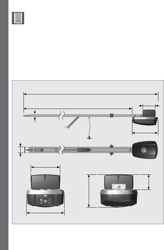
2.1. Physical dimensions |
|
||
GENERAL |
|
||
3293.1mm (Sectional) |
|
||
2173.1mm (Tip-up) |
|
||
|
2992.6mm (Sectional) |
104.5mm |
|
|
1872.6mm (Tip-up) |
|
|
|
28.4mm |
|
|
|
|
300.5mm |
|
|
70.6mm |
|
|
|
106mm |
|
|
|
175mm |
80mm |
|
|
211.2mm |
|
|
2 |
FIGURE 1. OVERALL DIMENSIONS FOR THE SDO4 |
||
SECTION |
|||
page 8 |
www.centsys.com |
||
|
|||

2.2. Technical specifications
|
T10 |
T12 |
|
|
Input voltage |
230V AC @ 50/60Hz1 |
|
||
Motor voltage |
24V DC |
|
||
Motor power - rated |
80W DC |
100W DC |
|
|
Motor supply |
Battery supply 2 x 3.4 Ah |
Battery supply 2 x 3.4 Ah |
||
24 V DC |
24 V DC |
|
||
|
|
|||
Max door width |
6500mm |
|
||
Max door area |
12m² |
15m² |
|
|
Max lifting capacity |
1000N |
1200N |
|
|
|
12 to 30 depending on the |
12 to 30 depending on the |
||
Operations in standby |
door size / weight / height |
door size / weight / height |
||
mode |
/ duration of power failure |
/ duration of power failure |
||
|
/ condition of batteries |
/ condition of batteries |
||
|
Tip-up: 80mm/sec. |
|
||
Operator travel speed |
Sectional: 140mm/sec |
|
||
|
with fully charged batteries. |
|
||
Door travel adjustment |
Physical Endstops (Automatic limit set) |
|
||
Safety obstruction force |
Built-in menu |
|
||
system |
|
|||
|
|
|
||
Light |
LED 2W |
|
||
Autoclose2 |
Menu Selectable |
|
||
Infrared safety beams |
Menu Selectable. |
|
||
(Optional, but recommended) |
|
|||
|
|
|||
Radio receiver |
Code-hopping 433MHz |
|
||
Receiver code storage |
20 transmitters (consisting of four buttons each) |
|||
capacity |
||||
|
|
|
||
|
|
|||
1: Can operate off a solar supply, please consult Centurion Systems (Pty) Ltd for assistance |
TABLE 1 |
|||
2: Requires infrared safety beams to be fitted |
|
|
||
2.3. Fuse protection
The following protection fuses are provided on the system:
Item |
Type |
Rating |
Main controller |
|
|
Motor circuit |
ATO |
15A |
TABLE 2
SPECIFICATIONS
www.centsys.com |
page 9 |
2 SECTION
IDENTIFICATION |
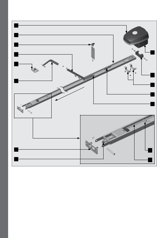
3. Product Identification |
|
|
||
1 |
|
|
|
|
|
2 |
|
|
|
|
|
|
|
|
|
|
|
PRODUCT |
3 |
|
|
|
|
|
|
|
END A |
15 |
|
4 |
|
|
|
||
|
|
|
|
||
|
|
|
|
|
|
|
5 |
|
|
|
|
|
|
|
|
|
14 |
|
6 |
|
|
|
|
|
|
|
|
|
13 |
|
|
|
garage |
door |
12 |
|
END B |
|
|
||
|
Towards |
|
|
||
|
|
|
|
||
|
|
|
|
11 |
|
|
|
|
|
|
|
|
|
|
|
END B |
|
|
7 |
|
|
|
10 |
|
8 |
|
|
|
9 |
FIGURE 2. PRODUCT IDENTIFICATION
SECTION 3
1. |
Control head unit |
9. Drive chain |
2. |
Rail |
10. End stop |
3. |
Release handle |
11. Carriage |
4. |
Straight towing arm |
12. Chain bullet |
5. |
Towing bracket |
13. Head unit brackets |
6. |
Bent towing arm |
14. Rail hanger |
7. |
Header bracket |
15. Battery housing |
8. |
Tensioning nut and spring |
|
page 10 |
www.centsys.com |
3.1. Fasteners list and spares
Description |
QTY |
|
ST5.5 x 50 Self-tapping Coach Screws |
4 |
|
ST8 x 60 Self-tapping Screws |
3 |
|
ST6.3 x 25 Self-tapping Screws |
3 |
|
- Hex Flange Head |
||
|
||
M6 x 8 Black Cross Pan Head Screws |
2 |
|
M8 x 20 Hexagon Head Bolts |
6 |
|
M6 x 12 Black Wizzlock Bolts |
4 |
Description |
QTY |
|
M8 Wizzlock Nuts |
8 |
|
Ø8 x 71 |
Clevice Pin |
1 |
Ø8 x 18 |
Black Clevice Pin |
1 |
Ø2 Hairpin Clips |
2 |
|
12 x 60mm Fischer Plugs |
3 |
|
M8 x 25(Pitch 1.25) Black Gutter Bolts |
2 |
|
TABLE 3
4. Required Tools and Equipment
|
Screwdrivers |
10mm, 12mm, |
|
|
3.5mm flat; |
||
Snips |
and 13mm |
||
No.2 Phillips |
|||
Sockets, |
|||
|
|
Socket wrench, |
|
|
|
and extension |
|
Measuring |
|
tape |
Electric drill |
|
Drill bits |
|
11mm & 6mm |
|
masonry; |
|
6mm drill bit |
10mm Coach |
|
screws |
|
(13mm hex head) |
|
and plugs |
2 Spirit levels |
|
|
Marking |
Extension cord |
pen/chalk/pencil |
FIGURE 3. REQUIRED TOOLS AND EQUIPMENT
EQUIPMENT AND TOOLS REQUIRED
www.centsys.com |
page 11 |
4 SECTION

PREPARATION OF SITE
5. Preparation of Site
5.1. General consideration for the installation
Always recommend the fitment of additional safety equipment such as safety edges and safety beams, for additional protection against entrapment or other mechanical risks.
Ensure that no pipes or electrical cables are in the way of the intended installation.
Install the garage operator only if:
•It will not pose a hazard to the public
•The installation will meet all municipal and/or local authority requirements once completed
•The door mass and application is within the operator specifications
•There is a properly-earthed general purpose 220-240V AC power outlet that has been installed by a qualified electrical contractor
•All locks, ropes and / or securing mechanisms have been removed
•The ceiling structure is adequate enough to support the weight of the SDO4
•The garage door is in good working order, meaning:
•it opens freely;
•it is well-balanced;
|
|
|
|
|
An improperly-balanced or malfunctioning garage door could cause |
|
|
|
|
|
serious personal injury, death and / or property damage. |
|
|
|
|
|
|
|
|
|
|
|
|
|
|
|
|
|
|
, |
|
|
|
|
Have a qualified person check and, if required, make repairs to the |
|
|
|
|
||
|
|
|
|
||
|
|
|
|
||
|
|
|
|
||
|
|
|
|
||
|
|
|
|
||
|
|
|
|
garage door before installing the SDO4. |
|
|
|
|
|
•it does not move on its own if left in any position for more than 100mm;
•it can be installed to have sufficient clearance between moving parts when opening or closing to reduce the risk of personal injury and / or entrapment
Any repairs to the garage door that need to be done due to any of the above requirements not being in place, must be carried out by technically qualified persons.
Attempting to repair the garage door without suitable technical qualifications, may result in severe personal injury, death, and / or property damage.
SECTION 5
page 12 |
www.centsys.com |
6. Operator Installation
6.1. Assembly instructions
6.1.1. Identify the garage door type
Identify the garage door type and then select the preferred installation method and assembly type that is best-suited to the application.
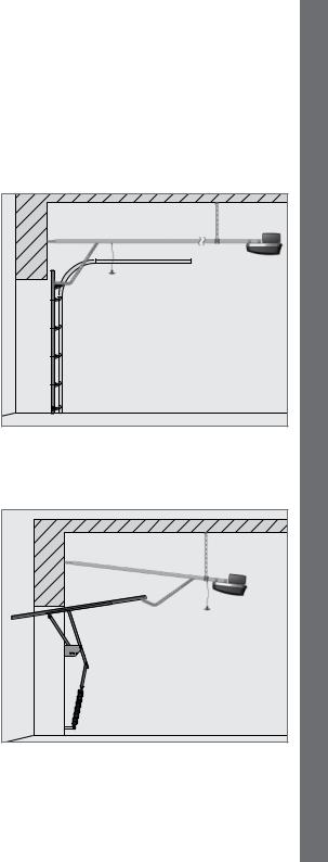
Sectional doors
•Use a 3000mm one-piece drive rail
•The standard 3000mm drive rail will lift a door up to 2440mm high. (An optional drive rail extension kit is available for doors over 2440mm high)
•The SDO4 is supported by the drive rail hanger which is hung from the ceiling using appropriate hanging material
•The drive rail must be parallel with the ceiling as shown in Figure 4.
•The header bracket may be mounted on the front wall of the garage or on the ceiling adjacent to the front wall
Tip-Up doors
•Use a 2000mm one-piece drive rail
•The SDO4 is supported by the drive rail hanger which is hung from the ceiling using appropriate hanging material
•The drive rail must be angled, so that the pivot points at each end of the connecting arm should be as close to horizontal as possible when the door is in the fully open position
•The header bracket may be mounted on the front wall of the garage or on the ceiling adjacent to the front wall
FIGURE 4
FIGURE 5
INSTALLATION OPERATOR
www.centsys.com |
page 13 |
6 SECTION
OPERATOR INSTALLATION
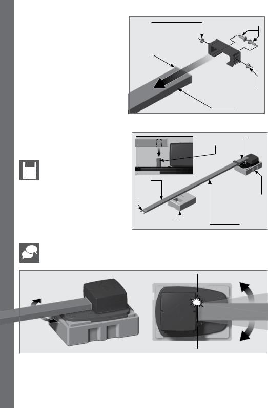
6.1.2. General assembly |
M8 Nut |
M8 Gutter bolts |
|
Open the packing carton and expose |
|
|
|
the SDO4 components. |
|
|
|
Orientate the drive rail so that the |
End ‘A’ |
|
|
terminal bracket faces towards the |
|
|
|
garage door |
|
|
|
1. Fit the M8 black gutter bolts onto |
|
|
|
the drive rail hanger. Secure |
|
M8 Nut |
|
them using the supplied M8 nuts. |
|
||
This must be done before fitting |
|
Drive Rail |
|
the drive rail hanger onto the |
|
||
Drive Rail. |
|
FIGURE 6 |
|
Fit the Drive Rail hanger and |
|
||
slide it down the Drive Rail |
|
|
|
starting from ‘End A’ (Figure 6). |
Motor |
End A |
|
|
Coupling |
|
|
It is important at this |
|
|
|
point of the installation to |
|
|
|
open the battery housing |
|
|
|
(Refer back to Figure 2), |
|
|
|
and connect the batteries |
End B |
|
|
before continuing with the |
|
||
|
|
||
installation. |
Terminal |
|
|
|
Bracket |
Operator |
|
2. Orientate the Drive Rail as shown |
|
still in packaging |
|
|
for support |
||
in Figure 7, and fit ‘End A’ over |
|
|
|
the motor coupling found on the |
Packaging used |
|
|
motor. |
Drive Rail |
||
for support |
|||
|
|
FIGURE 7 |
Keep the operator in its packaging for support, and use the other half of the packaging to support the other end of the Drive Rail.
SECTION 6
MAX 25°
MAX 25°
FIGURE 8
3.Swing the track from side to side should the motor coupling struggle to engage with the shaft. DO NOT exceed 25° in either direction.
page 14 |
www.centsys.com |
4.Place the two U-Brackets into position over the four holes found on the head unit (Figure 9).
5.Secure the U-Brackets into position using 4x black M6x12mm screws supplied (Figure 10).
U-Brackets
INSTALLATION OPERATOR
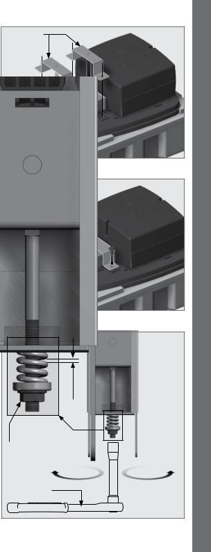
6.1.3. Tensioning the chain
The chain comes pre-tensioned from the factory; however, ensure that the spaces between the spring windings are 0.5-1mm. Use a 13mm socket wrench to tighten the drive should there, for whatever reason, be a deviation from these values.
www.centsys.com
FIGURE 9
M6x12mm
Screws
FIGURE 10
1mm-5.0
End B
Drive chain tensioning bolt
To relax the |
To tension the |
drive chain |
drive chain |
13mm Socket wrench
FIGURE 11
page 15
6 SECTION
OPERATOR INSTALLATION
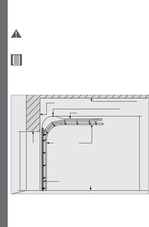
6.2. Installation instructions
6.2.1. Sectional doors (For Tip-up doors skip to Section 6.2.2)
Before commencing the installation, ensure that you have carefully read and understood all safety recommendations. In particular, ensure that the installation of the garage door complies with the requirements specified. Make any necessary adjustments to the garage door BEFORE commencing the installation!
Important considerations to note before commencing installation
•The opening heights are 2135mm for standard doors, or 2540mm for caravan height doors
•The structure is level, square and plumb
•For sectional doors, the door panel overlaps the opening by no more than 30mm at the top, and sides.
Door traveling path
The travel path of a garage door is determined by the path the top section of the garage door takes as the door is being opened or closed.
|
|
Header |
Ceiling |
|
|
|
|
|
|
|
Highest arcing point |
|
|
|
Travel path of the topmost section of the garage door |
|
Lintel |
Garage door track |
Floor |
|
|
||
|
|
level highrise to |
|
Opening height |
|
|
|
|
|
Garage door |
Floor |
|
|
|
FIGURE 12
SECTION 6
page 16 |
www.centsys.com |
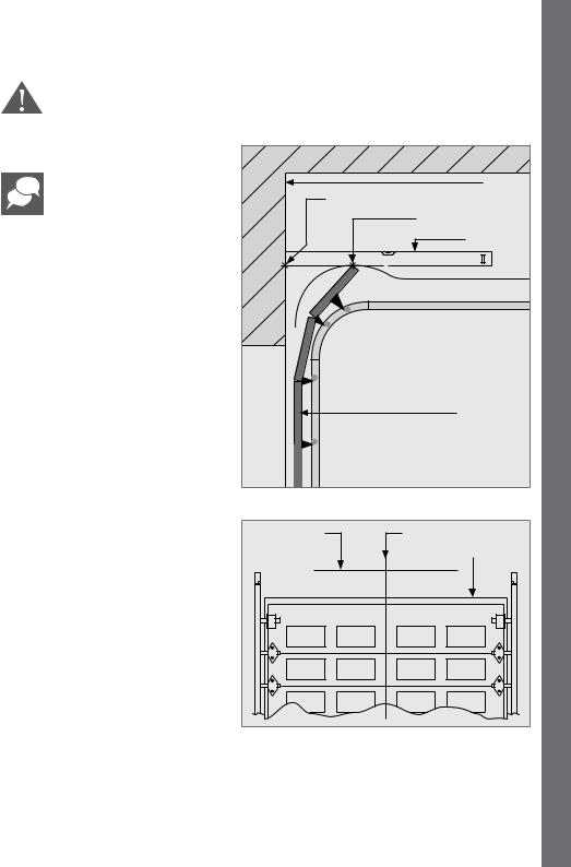
6.2.1.1. Mounting the header bracket
The header bracket carries ALL of the opening and closing thrust of the SDO4 and as such must be securely fastened to a rigid, structural member of the garage. It is entirely up to the installer to determine the fixing method and the structural suitability of the fixing points.
When marking important lines needed for mounting the header bracket, ensure that a spirit level is used, as it is imperative that these lines are as level and straight as possible.
Determine the highest arcing point of the garage door and mark this as a horizontal line on the header above the top edge of the garage door.
Close the garage door, and determine the garage door center line and mark a vertical line on the header above the door.
Header |
Highest arcing point marked on header |
Highest arcing point |
Spirit level |
Garage door |
FIGURE 13
Highest arcing |
Garage door centre line |
point |
Garage door |
|
FIGURE 14
INSTALLATION OPERATOR
www.centsys.com |
page 17 |
6 SECTION
OPERATOR INSTALLATION
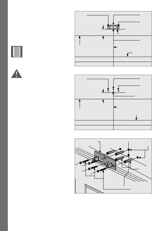
Place the header bracket on the wall as shown in Figure 15. Ensure that the bottom edge of the bracket is level, and no more than 50mm above the highest arcing point of the garage door. Mark the location of the four screw
holes (Hole A, B, C and D[optional]).
Note the orientation of the header bracket.
Mounting the drive rail more than 50mm above the highest arcing point of the garage door may cause the drive rail to flex excessively.
Drill four 11mm diameter holes in position of ‘Hole A’, ‘Hole B’, ‘Hole C’ and ‘Hole D’(optional), at least
50mm deep.
Place a fischer plug in each hole, followed by the header bracket. Secure it in position with at least three coach screws (supplied) (13mm hexagonal head).
Hole A |
|
Hole B |
|
|
Hole C |
|
0-50mm |
Header bracket |
|
(Note the orientation) |
|
|
|
|
|
|
Hole D |
|
|
(Optional) |
Highest arcing |
|
Garage door center line |
point |
|
|
|
|
Garage door |
FIGURE 15
Hole A |
Hole B |
|
Hole C |
0-50mm |
Hole D |
(Optional) |
|
|
Garage door center line |
Highest arcing |
|
point |
Garage door |
FIGURE 16
Header bracket |
11mm |
|
Holes |
|
Plugs |
|
Coach screws |
FIGURE 17
SECTION 6
page 18 |
www.centsys.com |
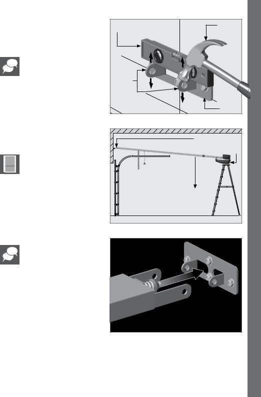
If after securing the header bracket, it is slightly out (not level), use a hammer to knock the tabs gently up or down with a small spirit level placed on top of them. This will ensure a perfectly level installation (Figure 18).
Small spirit |
Hammer |
OPERATOR |
level |
|
|
|
|
|
Header |
|
INSTALLATION |
bracket |
|
|
tabs |
|
|
|
|
|
|
Header |
|
|
bracket |
|
FIGURE 18
6.2.1.2.Mounting the SDO4 to the header bracket
It is important at this point of the installation to ensure that the batteries are connected before continuing with the installation.
Position the SDO4 in place, with the open end of the drive rail facing the floor, and the tensioning bracket towards the garage door. You will need a second person to assist you with this.
If you are on your own, use a ladder to support the control unit end of the SDO4 while you are positioning it for the next step (Figure 19).
Align the holes on the side of the tensioning bracket with the holes of the header bracket.
Tensioning bracket |
Driver head unit |
Face down |
FIGURE 19
FIGURE 20
www.centsys.com |
page 19 |
6 SECTION
OPERATOR INSTALLATION
|
Circle Clip |
|
Locate the long clevis pin through |
Header bracket |
|
the holes and secure it into position |
|
|
with a supplied Circle Clip on the |
Clevis |
|
other end of the clevis pin. |
||
pin |
||
Dowel split pins have also |
|
|
been supplied should they |
|
|
be preferred over the use of |
|
|
the circle pin clips. |
|
|
|
SDO4 |
|
|
drive rail |
|
|
FIGURE 21 |
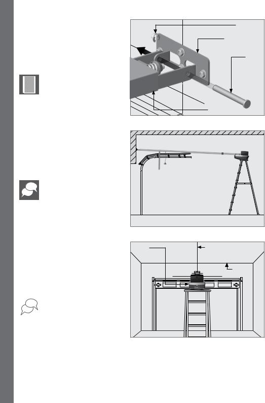
6.2.1.3.Mounting the SDO4 drive rail to the ceiling
Open the garage door, and gently rest the SDO4 on top of the open door.
If your ladder is high enough, we recommend resting it on top of the ladder.
Find the centre line of the garage door, and mark it on the ceiling above the location of the drive rail hanger.
 You can use the SDO4 drive rail as a gauge to assist you if needed.
FIGURE 22
SDO4 |
Garage door center line |
|
Ceiling |
|
FIGURE 23 |
SECTION 6
page 20 |
www.centsys.com |
 Loading...