


DOMASTIC SLIDING GATE OPERATOR
D2 TURBO AND D2 TURBO LOW-VOLTAGE
INSTALLATION MANUAL
Centurion Systems (Pty) Ltd

COMPANY PROFILE
Company Profile
1986 |
1990 |
1995 |
|
1999 |
Today |
|
In-house |
|
|
|
|
|
Manufacture to |
R&D |
|
|
|
|
|
international |
development |
|
|
|
|
|
standard |
team |
|
|
|
|
|
9001:2008 |
|
|
|
|
|
|
|
|
|
|
|
|
|
|
|
|
|
|
|
|
|
|
|
|
|
|
|
|
|
After-sales |
|
-language |
|
Support |
100% |
to 18h00 |
testing of |
UTC+2 |
products |
to Friday |
|
|
Sales and technical support to Africa, Europe, Asia, the Americas, Australia and the Pacific
Centurion Systems (Pty) Ltd reserves the right to make changes to the products described in this manual without notice and without obligation to notify any persons of any such revisions or changes. Additionally, Centurion Systems (Pty) Ltd makes no representations or warranties with respect to this manual. No part of this document may be copied, stored in a retrieval system or transmitted in any form or by any means electronic, mechanical, optical or photographic, without the express prior written consent of Centurion Systems (Pty) Ltd.

Contents
FAST |
Mechanical Setup |
|
Electrical Setup |
||
TRACK |
||
|
Commissioning and Handover |
|
|
|
|
SAFETY |
IMPORTANT SAFETY INSTRUCTIONS |
|
FIRST |
||
|
|
Glossary of Terms
1.General Description
2.Icons Used in this Manual
3.Specifications
3.1.Physical Dimensions
3.2.Technical Specifications
4.Product Identification
5.Required Tools and Equipment
6.D2 Turbo Low-voltage Site Considerations
7.Preparation of Site
8.Cabling Requirements
9.Lubrication
10.Operator Installation
10.1.Foundation plate installation
10.2.Route Cables and Secure Foundation Plate
10.3.Mount the gearbox
10.4.Mount the rack
10.5.Mount the origin marker
10.6.Apply warning decal
11.Electrical Setup
11.1.Connect all Wiring
11.2.Wiring Diagram for Closing Safety Beams/ Photocells
11.3.Wiring Diagram for Opening Safety Beams/ Photocells
11.4.Wiring Diagram for External Radio Receiver
CONTENTS
page 5 page 6 page 6
page 7
page 9 page 11 page 12 page 13 page 13 page 13 page 15 page 16 page 17 page 18 page 21 page 22 page 23 page 25 page 31 page 31 page 34 page 38 page 41 page 42 page 42 page 43 page 44 page 45
www.CentSys.com |
page 3 |

CONTENTS
11.5. |
Wiring Diagram for Closing Safety Beams/ Photocells |
page 46 |
11.6. |
Wiring Diagram for Opening Safety Beams/ Photocells |
page 47 |
11.7. |
Wiring Diagram for Other Inputs |
page 49 |
11.8. |
Wiring Diagram for Pillar Light to D2 Turbo |
page 50 |
11.9. |
Wiring Diagram for Pillar Light to D2 Turbo Low-Voltage |
page 51 |
11.10. |
Wiring Diagram for Solar Panel to D2 Turbo |
page 52 |
11.11. |
Wiring Diagram for Solar Panel to D2 Turbo Low-Voltage |
page 55 |
11.12. |
Mains Supply and Battery Connections |
page 56 |
11.13. |
Earthing for Effective Lightning Protection |
page 56 |
12. |
Commissioning the System |
page 58 |
13. |
Features and Functions |
page 60 |
14. |
Customising the Features and Functions |
page 72 |
15. |
Description of Terminal Functions |
page 91 |
16. |
Diagnostics |
page 93 |
17. |
Troubleshooting |
page 91 |
18. |
Manual Operation |
page 95 |
19. |
Additional Features |
page 96 |
20. |
Basic Maintenance |
page 95 |
21. |
Servicing the Operator |
page 98 |
22. |
24 Month Carry-in Product Warranty |
page 99 |
23. |
Installation Handover |
page 102 |
page 4 |
www.CentSys.com |

FAST TRACK Mechanical Setup
These abbreviated instructions are for the experienced installer who needs a checklist to get a standard installation up and running in the minimum of time.
Detailed installation features and functions are referred to later in this manual.
STEP |
Gather Required Tools and Equipment |
page 16 |
|
1 |
|||
|
|
||
|
|
|
|
STEP |
Heed Necessary Site Considerations |
page 17 |
|
2 |
|||
|
|
||
|
|
|
|
STEP |
Cabling requirements |
page 21 |
|
3 |
|||
|
|
||
|
|
|
|
STEP |
Lubrication |
page 22 |
|
4 |
|||
|
|
||
|
|
|
|
STEP |
Operator installation |
page 23 |
|
5 |
|||
|
|
||
|
|
|
|
STEP |
Foundation plate installation |
page 25 |
|
6 |
|||
|
|
||
|
|
|
|
STEP |
Cabling and Wiring |
page 31 |
|
7 |
|||
|
|
||
|
|
|
|
STEP |
Mount Gearbox |
page 31 |
|
8 |
|||
|
|
||
|
|
|
|
STEP |
Mount the Rack |
page 34 |
|
9 |
|||
|
|
SETUP MECHANICAL
TRACK FAST
www.CentSys.com |
page 5 |

MECHANICAL SETUP
Electrical Setup
STEP |
Connect all wiring |
|
10 |
||
|
||
|
|
|
STEP |
Set the gate limits |
|
11 |
||
|
||
|
|
|
STEP |
Set additional features |
|
12 |
||
|
Commissioning & Handover
STEP |
Carry out a Professional Handover to Client |
|
13 |
||
|
page 42
page 53
page 67
page 99
FAST TRACK
page 6 |
www.CentSys.com |

IMPORTANT
SAFETY INSTRUCTIONS
ATTENTION
To ensure the safety of people and possessions, it is important that you read all the following instructions.
Incorrect installation or incorrect use of the product could cause serious harm to people.
The installer, being either professional or DIY, is the last person
on the site who can ensure that the operator is safely installed, and that the whole system can be operated safely.
INSTRUCTIONS SAFETY IMPORTANT
Warnings for the Installer
CAREFULLY READ AND FOLLOW ALL INSTRUCTIONS before beginning to install the product.
• All installation, repair, and service work to this product must be carried out by a
suitably qualified person |
|
|
• This appliance is not intended for use by persons (including children) with reduced |
|
|
physical, sensory or mental capabilities, or lack of experience and knowledge, |
|
|
unless they have been given supervision or instruction concerning use of the |
|
|
appliance by a person responsible for their safety |
|
|
• Do not activate your gate unless you can see it and can determine that its area of |
|
|
travel is clear of people, pets, or other obstructions |
|
|
• NO ONE MAY CROSS THE PATH OF A MOVING GATE. |
|
|
• Always keep people and objects away from the gate and its area of travel |
|
|
• NEVER LET CHILDREN OPERATE OR PLAY WITH THE GATE CONTROLS |
|
|
• Secure all easily-accessed gate opener controls in order to prevent unauthorised use |
|
|
of the gate |
|
|
• Do not in any way modify the components of the automated system |
|
|
• Do not install the equipment in an explosive atmosphere: the presence of flammable |
|
|
gasses or fumes is a serious danger to safety |
|
|
• Before attempting any work on the system, cut electrical power to the operator and |
|
|
disconnect the batteries |
|
|
• The mains power supply of the automated system must be fitted with an all-pole |
|
|
switch with contact opening |
SAFETY |
|
• Never short-circuit the battery and do not try to recharge the batteries with |
||
• Make sure that an earth leakage circuit breaker with a threshold of 30mA is fitted |
|
|
upstream of the system |
|
|
power supply units other than that supplied with the product, |
FIRST |
|
or by Centurion Systems (Pty) Ltd |
||
|
www.CentSys.com |
page 7 |

INSTRUCTIONS |
of the system are suitably earthed |
|
SAFETY |
• Make sure that the earthing system is correctly constructed, and that all metal parts |
|
• It is recommended that at least one warning indicator light be fitted to every system |
||
|
• Safety devices must be fitted to the installation to guard against mechanical |
|
|
movement risks such as crushing, dragging and shearing |
|
IMPORTANT |
• Always fit the warning signs visibly to the inside and outside of the gate |
|
• The installer must explain and demonstrate the manual operation of the gate in case |
||
|
||
|
of an emergency, and must hand the User Guide/Warnings over to the user |
|
|
• Explain these safety instructions to all persons authorised to use this gate, and be |
|
|
sure that they understand the hazards associated with automated gates |
|
|
• Do not leave packing materials (plastic, polystyrene, etc.) within reach of children as |
|
|
such materials are potential sources of danger |
|
|
• Dispose of all waste products like packing materials, wornout batteries, etc., |
|
|
according to local regulations |
|
|
• Always check the obstruction detection system, and safety devices for correct |
|
|
operation |
|
|
• Neither Centurion Systems (Pty) Ltd, nor any of its subsidiaries, accepts any liability |
|
|
caused by improper use of the product, or for use other than that for which the |
|
|
automated system was intended |
|
|
• This product was designed and built strictly for the use indicated in this |
|
|
documentation. Any other use, not expressly indicated here, could compromise the |
|
|
service life/operation of the product and/or be a source of danger |
SAFETY FIRST
page 8 |
www.CentSys.com |

Glossary of Terms
•DOSS: Digital Origin Seeking System. An opto-electronic system that counts pulses in order to determine the position of the gate and the distance that it needs to travel to its respective endstops
•IRBO: Opening infrared Safety Beams. If the opening beams are interrupted while the gate is in the closed position, it will prevent the gate from opening. If they are interrupted while the gate is travelling in the open direction, it will stop and close the gate. It will have no effect upon a closing gate
•IRBC: Closing infrared Safety Beams. If the closing beams are interrupted while the gate is in the open position, it will prevent the gate from closing.
If they are interrupted while the gate is closing, it will stop and open the gate.
It will have no effect upon an opening gate
•PIRAC Mode: Passive infrared Autoclose Mode. This feature allows the gate to close automatically as soon as a vehicle or pedestrian has passed through the closing beam. This security feature ensures that the gate stays open for the minimum amount of time possible, thus maximising security at the entrance
TERMS OF GLOSSARY
www.CentSys.com |
page 9 |

DECLARATION OF CONFORMITY
Declaration of Conformity
Manufacturer
Centurion Systems (Pty) Ltd
Unit 13 Production Park
Intersection of Newmarket Road and Epsom Avenue
North Riding
Gauteng
South Africa
Declares that the product
Product name: D2 Turbo/D2 Turbo Low-Voltage Sliding gate operator.
Conforms with the following specifications
Emissions: |
CISPR 11 CLASS A - Radiated and conducted Interference field |
|
|
strength (emission tests) – 150KHz TO 6GHz |
|
Immunity: |
IEC 61000-4-2 – Electrostatic discharge |
|
|
IEC 61000-4-3 |
– Radiated immunity – 80MHz TO 1000MHz |
|
IEC 61000-4-4 |
– Electrical fast transients/burst |
|
IEC 61000-4-5 |
– Surges |
|
IEC 61000-4-6 |
– Conducted immunity – 150KHz TO 80MHz |
IEC 61000-4-11– Voltage dips and interruption
Standard to which conformity is declared
IEC 60335-1:2006 |
Safety |
IEC 61000-6-4:2006 |
Emissions |
IEC 61000-6-2:2005 |
Immunity |
Signed at North Riding, South Africa on April 14, 2010
Ian Rozowsky
Research & Development Director
page 10 |
www.CentSys.com |
1. General Description
The D2 Turbo is designed to open and close domestic sliding gates weighing up to 250kg. The gearbox, moulded from a high-tech engineering polymer not only looks good, but is corrosion-free and guarantees that even if you live on the coast, your D2 Turbo will just keep on going. A robust steel pinion ensures that your D2 Turbo can easily be retrofitted on sites with existing steel rack and will deliver years of reliable service.
The D2 Turbo Low-Voltage is a cost-effective domestic sliding gate motor for gates weighing up to 250kg. Its logic controller and onboard charger require only a low-voltage AC or DC input, which means there is no need for costly high-voltage cable runs or expensive isolators.
The integral 12V 5Ah battery (charged by an internal charger) comes with full battery backup and advanced lightning protection so you can always get in – even when the power is out.
For increased power capacity you can install a larger, 7Ah battery (your D2 Turbo was designed to cater for this), or you can even use a solar panel to power it (See the section on Solar Panels, for more details about solar charging).
Advanced features of the D2 Turbo logic controller:
The D2 Turbo has various useful features and functions, all easily-accessible from a user-friendly dial-based setup system:
•Opening and closing safety beam inputs with beam circuit functional test1
•High-security cleared-beam Autoclose in conjunction with safety beams (PIRAC)1
•Multiple Modes of Operation: Standard Mode, Open only Mode (multi-user),
Reversing Mode, and two Pre-flashing Modes
•Automatic closing with adjustable time delay, and pushbutton override
•Remote gate-status indicator (gate position, power failure, low battery, multiple collision detection and Pillar Light status indication)2
•Pedestrian Opening3 (with adjustable Autoclose time)
•Holiday Lockout3
•Courtesy/Pillar-Light timer (fixed duration), with pre-delays and two Pre-flashing Modes4
•Selectable gate speed modes - Low Speed/High Speed (High Speed is the default)
•Positive Close Mode (e.g. ensure activation of electric fence contact switch)
•Onboard multichannel code-hopping receiver with the ability to learn transmitter buttons to specific functions (e.g. Gate trigger, Pedestrian Opening, Holiday Lockout)
1.Infrared Safety Beams or equivalent detection device must be fitted
2.Remote LED must be fitted
3.Onboard receiver must be used or external access control device such as a keypad or keyswitch that must be fitted
4.Pillar Lights/Pre-flash warning light must be fitted
DESCRIPTION GENERAL
www.CentSys.com |
page 11 |
1 SECTION

ICONS USED IN THIS MANUAL
2. Icons Used in this Manual
This icon indicates tips and other information that could be useful during the installation.
This icon denotes variations and other aspects that should be considered during installation.
This icon indicates warning, caution or attention! Please take special note of critical aspects that MUST be adhered to in order to prevent injury.
SECTION 2
page 12 |
www.CentSys.com |
3. Specifications |
SPECIFICATIONS |
3.1. Physical Dimensions |
|
|
|
|
310mm |
|
60mm |
244mm |
170mm |
FIGURE 1. OVERALL DIMENSIONS
3.1. Technical specifications
|
D2 Turbo |
|
D2 Turbo Low-Voltage |
||
Supply Voltage |
90V - 240V AC |
10V - 20V AC1 |
|||
± 10%, 50Hz1 |
10V - 28V DC1 |
||||
|
|||||
|
Voltage output: 13.76V DC |
|
|||
|
|
|
10V AC |
400mA |
|
|
90V AC |
1A |
Input |
Output |
|
Battery Charger Amperage |
Input |
Output |
20V AC |
1A |
|
|
|
||||
Output (dependant on PSU |
|
|
Input |
Output |
|
input voltage) |
|
|
10V DC |
200mA |
|
|
|
|
|||
|
240V AC |
1.2A |
Input |
Output |
|
|
Onput |
Output |
20V DC |
1A |
|
|
|
|
Input |
Outpu |
|
Motor voltage |
|
12V DC |
|
||
Motor Power Supply |
Battery-driven (Standard Capacity - 12V 5Ah)2 |
||||
Current Consumption (mains) |
70mA |
|
NA |
|
|
www.CentSys.com |
page 13 |
|
|
|
|
3 SECTION

SPECIFICATIONS
SECTION 3
|
D2 Turbo |
D2 Turbo Low-Voltage |
|
Current Consumption (motor |
|
8A |
|
at rated load) |
|
||
|
|
||
Operator Push Force - |
|
18kgf |
|
Starting |
|
||
|
|
||
Operator Push Force - Rated |
|
9kgf |
|
Gate Mass - Maximum |
|
250kg |
|
Gate Length - Maximum |
|
20m |
|
Gate Speed (Varies with |
|
24m/min |
|
Load)3 |
|
||
|
|
||
Manual Override |
Lockable with Key Release |
||
Life Expectancy of Electric |
Ten Years (based on ten operations per day) |
||
Motor |
|||
|
|
||
Duty Cycle - Mains Present4,5 |
|
50% |
|
Operations in Standby with |
|
|
|
5Ah Battery |
|
|
|
Half Day6 |
|
30 |
|
Full Day6 |
|
15 |
|
Collision Sensing |
|
Electronic |
|
Operating Temperature |
|
-15°C to +50°C |
|
Range |
|
||
|
|
||
Onboard Receiver Type |
Code-hopping Multichannel Receiver with Selective add |
||
|
and Delete |
||
|
|
||
Receiver Code Storage |
32 Transmitter Buttons |
||
Capacity |
|||
|
|
||
Receiver Frequency |
|
433.92MHz |
|
Degree of Protection |
|
IP44 |
|
Mass of Unit Packed (with |
|
|
|
standard kit, but excl. rack |
|
4.83kg |
|
and battery) |
|
|
|
Packaging Dimensions (with |
|
|
|
standard kit, but excl. rack |
255mm wide x 188mm deep x 333mm high |
||
and battery) |
|
|
|
TABLE 1
1.Can operate off a solar supply, consult your local dealer for assistance
2.Can increase battery capacity to 7Ah for longer standby times
3.Gate operating speed can be configured to run slower depending on the requirements of individual installations
4.Based on 25°C ambient temperature and unit not in direct sunlight
5.Based on an operator push force of less than 50% of rated
6.Based on four metre gate, excluding infrared Safety Beams
page 14 |
www.CentSys.com |
4. Product Identification
Refer to the drawings below, for how to identify your D2 Turbo/D2 Turbo Low-Voltage motor and its parts.
|
|
|
|
|
|
|
|
|
|
10 |
||
|
|
|
|
|
|
|||||||
|
|
|
|
|
|
|
|
|
|
|
|
|
1 |
|
|
|
|
|
|
|
|
|
|
|
11 |
|
|
|||||||||||
|
|
|
|
|
|
|
|
|
|
|||
|
|
|
|
|
|
|
|
|
|
|
|
12 |
|
|
|
|
|
|
|
|
|
|
|
|
|
2 |
|
|
|
|
|
|
|
|
|
|
|
|
|
|
|
|
|
|
|
|
|
|
|
13 |
|
|
|
|
|
|
|
|
|
|
|
|
||
|
|
|
|
|
|
|
||||||
|
|
|
|
|
|
|
|
|
|
|||
|
|
|
|
|||||||||
|
|
|
|
|
|
|
|
|
|
|
|
|
3 |
|
|
|
|
|
|
|
|
|
|
|
|
|
|
|
|
|
|
|
|
|
|
|
|
|
|
|
|
|
|
|
|
|
|
|
|
14 |
|
|
|
|
|
|
|
|
|
|
|
|
||
|
|
|
|
|
|
|
|
|
|
|
|
|
|
|
|
|
|
|
|
|
|
|
|
|
|
|
|
|
|
|
|
|
|
|
|
|
|
|
4 |
15 |
|
|
|
|
|
|
|
|
16 |
|
|
|
|
|
|
|
|
5 |
|
|
|
|
|
|
|
|
|
|
|
|
|
||
|
|
|
|
|
|
|
|
|
|
|
|
|
|
|
|
|
|
|
|
|
|
|
|
6 
19
7 
8
17
9
18
|
|
FIGURE 2. PRODUCT IDENTIFICATION |
|
1. |
Motor fuse |
11. Status LED |
|
2. |
D2 Turbo 220V orange controller and |
12. Function Dial |
|
|
D2 Turbo Low-Voltage dark-green |
13. Selection knob |
|
|
controller |
||
|
14. Battery strap |
||
3. |
12V 7.2Ah or 5Ah battery |
||
15. Spare fuse |
|||
4. |
Motor enclosure unit |
||
16. Pulley guard |
|||
5. |
Camlock cover |
||
17. Pinion |
|||
6. |
Manual Release thumbwheel |
||
18. Pinion guard |
|||
7. |
Foundation plate |
||
19. Motor housing |
|||
8. |
Gate-mounted origin marker |
||
|
|||
9. |
Origin marker bracket |
|
|
10.Selection knob |
|
||
www.CentSys.com |
page 15 |
||
IDENTIFICATION PRODUCT
4 SECTION
REQUIRED TOOLS & EQUIPMENT
SECTION 4
5. Required Tools & Equipment
Screwdrivers
6mm Phillips
3.5mm Flat
Pliers
Hammer
Electric drilling machine
Spanners 17mm/15mm preferably socket set
Crimping tool |
Connector |
|
block |
|
|
and Pin lugs |
|
|
|
G-clamps |
|
|
|
|
|
|
x2 |
|
Hole saw |
Allen key |
|
20mm |
5mm |
|
Angle grinder |
|
|
Pin punch |
Measuring |
Ø12mm masonry drill bit for |
6mm |
tape |
|
|
|
wall mount bracket |
|
|
Ø6.5mm steel drill bit |
|
|
for gate bracket |
|
|
|
Spirit level |
|
Hacksaw |
Welding machine |
|
|
(including consumables) |
|
|
and safety equipment |
|
|
Marking |
|
|
pen/chalk |
|
|
Soldering |
|
|
iron |
|
Extension cord |
Safety equipment |
|
|
||
|
(goggles, gloves etc.) |
|
|
|
|
|
FIGURE 3. REQUIRED TOOLS & EQUIPMENT |
|
|
page 16 |
www.CentSys.com |

6. D2 Turbo Low-voltage Site Considerations
IMPORTANT Site Considerations for the D2 Turbo Low-Voltage
Before you attempt to use your new gate motor for the first time, you should know::
•At no point must 220V be supplied to the system! This is a low-voltage model and connecting a mains voltage supply that exceeds its maximum specifications will irreparably damage the electronics
•No earth terminal is provided for the incoming power, and is not necessary, but the earthing lead must still be grounded to the motor base plate as this serves as lightning protection
•The thickness of the cable needed to supply power to the system will depend on the distance between the transformer and the motor, as well as on the output voltage of the transformer used. The table below shows the typical cable thicknesses for corresponding distance and assumes a 16V AC transformer output
Distance from transformer to operator |
Minimum cable thickness required |
Up to 20m |
1mm2 |
20m - 40m |
1.5mm2 |
40m - 60m |
2.5mm2 |
CONSIDERATIONS SITE VOLTAGE-LOW TURBO D2
SECTION
www.CentSys.com |
page 17 |
6
PREPARATION OF SITE
SECTION 7
7. Preparation of Site
WARNING!
Endstops are mandatory and must be fitted to prevent death
or accidental injury should the gate overrun its limit. They are also required to complete the setup procedure.
7.1. Endstops
Fit endstops capable of stopping the gate at rated speed. Refer to specifications at the beginning of this manual for the operating speed
Make H>h to ensure gate will not jump over endstop
Endstop
|
|
|
|
|
|
|
|
Endstop |
|
|
|
|
|
|
|
|
|
H |
|
|
h |
|
Ø16mm |
|
||
|
|
|
||||||
|
|
|
|
|||||
|
|
|
|
|
|
|
||
FIGURE 4. FITTING ENDSTOPS
7.2. General Considerations for the Installation
Always recommend the fitment of additional safety equipment such as Safety Edges and Safety Beams/Photocells, for additional protection against entrapment or other mechanical risks.
Check that no pipes or electrical cables are in the way of the intended installation
Check that enough space is available for the gate operator with the gate in the required open position.
Check for loose, sandy soil if installing foundations, as the soil condition may require a larger foundation.
Never fit the operator on the outside of the gate, where the public has access to it.
7.3. Install the gate operator only if:
It will not pose a hazard to the public.
There is sufficient clearance to a roadway and/or public thoroughfares
page 18 |
www.CentSys.com |
The installation will meet all municipal and/or local authority requirements once completed.
The gate mass, length and application is within the operator specifications
The gate is in good working order, meaning:
•That it moves freely
•Does not move on its own if left in any position
•It can be installed to have sufficient clearance between moving parts when opening and closing to reduce the risk of personal injury and entrapment
Pushbuttons or keyswitches, when required, can be positioned so that the gate is in line of sight of the operator
7.4. Guide-rollers and anti-lift brackets
Guide-rollers must ensure that the gate is held vertically
For improved safety, fit additional support post to prevent gate from falling over if guide-rollers fail
To prevent unauthorised access fit anti-lift brackets as shown
The gap between the anti-lift bracket and the gate must be less than 5mm
Ensure that the gate cannot be lifted off the motor pinion with the anti-lift bracket fitted.
GAP <5mm |
GAP <5mm |
Guide-rollers
Additional support post
GAP <5mm |
GAP <5mm |
FIGURE 5. FITTING GUIDE-ROLLERS
www.CentSys.com |
page 19 |
SITE OF PREPARATION
7 SECTION
PREPARATION OF SITE
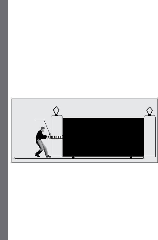
7.5. Starting and running forces
Test the starting force of the gate as per Figure 6. Use a pull scale to determine the maximum amount of pull force required to get the gate moving
Determine the running force of the gate by continuing to pull on the scale with just sufficient force to keep it running and read off the maximum value in kgf shown on the scale
Where possible determine the gate mass
The warranty will be void if the pull force and/or gate mass exceed the operator specification as below:
•Starting force - 18kgf
•Running (rated) force - 9kgf
•Maximum gate mass - 250kgf
Pull scale |
FIGURE 6. STARTING AND RUNNING FORCES
SECTION 7
page 20 |
www.CentSys.com |
8. Cabling Requirements
8
Mains |
|
|
|
|
|
|
|
|
|
|
|
|
|
|
|
|
|||||
isolator |
|
|
|
|
|
|
|
|
|
|
|
|
|
|
|
|
|
||||
switch |
|
|
|
|
|
|
|
|
|
|
|
|
|
|
|
|
|||||
|
|
|
|
|
|
|
|
|
|
|
|
|
|
|
|
|
|
|
|
|
|
|
|
|
|
|
|
|
|
|
|
|
|
|
|
|
|
|
|
|
|
||
|
|
|
|
|
|
|
|
|
|
5 |
|
|
|
|
|
|
|
|
|
|
|
|
|
|
|
|
|
|
|
|
|
|
|
|
|
|
|
|
|
|
|
|
|
|
|
|
|
|
|
|
|
|
|
|
|
|
|
|
|
|
4 |
|
|
|
|
|
|
|
|
|
|
|
|
|
|
|
|
|
|
|
2 |
|
|
8 |
|||
|
|
|
|
|
|
|
|
|
|
|
|
|
|
|
|
|
|
|
|
||
|
|
1 |
|
|
|
|
|
|
|
|
|
3 |
|
|
|
|
|
|
|
|
|
|
|
|
|
|
|
|
|
|
|
|
|
|
|
|
|
|
|
|
6 |
|
|
2 |
|
|
|
|
|
|
|
|
|
|
|
|
|
|
|
|
|
|
|
|
|
|
|
|
|
|
1 |
|
|
|
|
|
|
|
|
|
|
|
|
|
|||
|
|
|
|
|
|
|
|
|
|
|
|
|
|
|
|
|
|
|
|||
|
|
|
|
|
|
|
|
|
|
|
|
|
|
|
|
|
|
||||
|
3 |
|
|
|
|
|
|
|
|
|
|
|
|
|
|
|
|
|
|||
|
|
|
9 |
|
|
|
|
|
|
|
|
|
|
|
|
||||||
|
|
|
|
|
|
|
|
|
|
|
|
|
|
|
|
|
|
|
|
|
|
REQUIREMENTS CABLING
FIGURE 7. CABLING REQUIREMENTS
Legend
1.D2 Turbo: 220V - 240V AC mains cable via double mains isolator switch
(3 core LNE 1.5mm2 SWA) D2 Turbo Low-Voltage: 10V - 20V AC or 10-28V DC cable via transformer in dwelling1
Optional Wiring (all cable is multi-stranded):
2.Intercom, cable from control box to dwelling (n1 6 + 6 core 2 0.5mm² multistranded) or cable from control box to entry panel (n2 6 0.5mm² multi-stranded)
3.Infrared Safety Beams (3 core 0.5mm² multi-stranded)
4.Access control device (3 core 0.5mm² multi-stranded4)
5.Pedestrian keyswitch (2 core 0.5mm² multi-stranded) or
6.Keypad (3 core 0.5mm² multi-stranded)
7.External radio receiver (3 core 0.5mm² multi-stranded5)
8.Pillar Lights (3 core LNE SWA2, size according to power requirements)
9.Inductive loop detector for free-exit
(1 core 0.5mm² multi-stranded - silicone-coated6)
1.Possibly increase cable thickness if Pillar Lights are to be installed
2.SWA - steel wire armoured. Type of cable must adhere to municipal bylaws and preferably be screened. Screening provides better protection against lightning - earth one end of the screening
3.Allows for all features such as Pedestrian Opening, Status LED, etc. to be operated from the intercom handset inside the dwelling
4.Number of cores and type of cable could vary depending on the brand of access control system being used
5.For optimum range an external radio receiver can be mounted on the wall
6.Number of cores required by the intercom
www.CentSys.com |
page 21 |
8 SECTION

LUBRICATION
9. Lubrication
The gearbox of the D2 Turbo is filled with grease during the assembly process, and the gearset does not have to be lubricated ex-factory.
SECTION 9
page 22 |
www.CentSys.com |
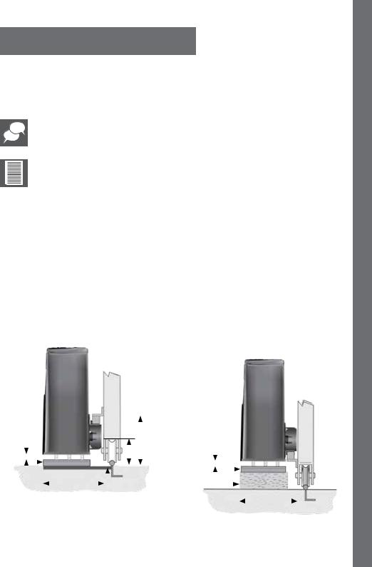
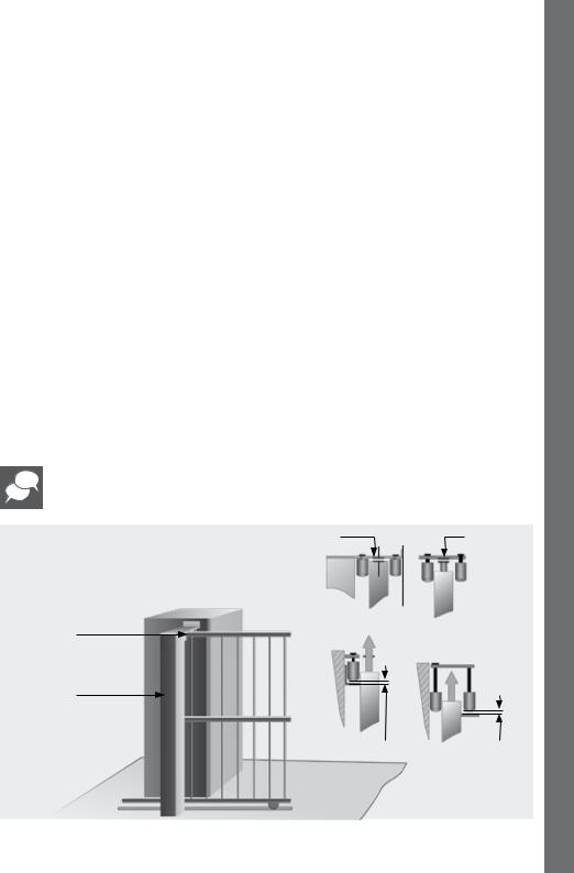
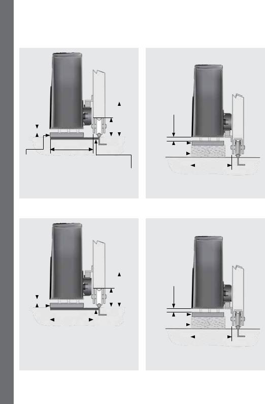
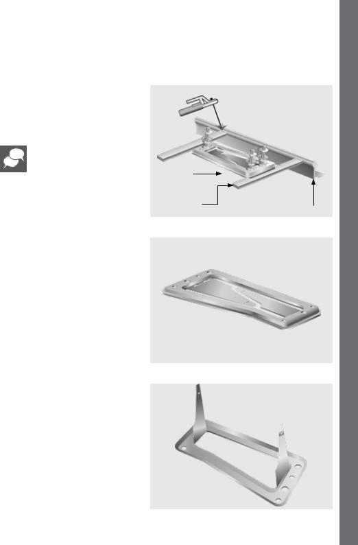
10. Operator Installation
To ensure operator does not protrude into the driveway, install the foundation plate at least flush with the driveway entrance
Determine a suitable position and vertical height for the operator by considering Figures 8, 9 and 10.
With careful selection of the rack configuration, and operator vertical height, mounting of the rack could in some cases be greatly simplified.
If a theft-resistant cage is required, be sure to leave enough clearance from pillars, etc.
It is typical to mount the rack above the pinion as shown in figures 8A, 9A and 10A for each type of rack considered. However, figures 8B, 9B and 10B show in each case the rack mounted underneath.
Pros of mounting the rack below the pinion
•The rack is more hidden from view
•It provides a very effective anti-lift bracket
•It ensures that as the gate beds in, the rack does not drop onto the pinion, loading the operator unnecessarily
Cons of mounting the rack below the pinion
•Rack teeth face up vertically, potentially collecting dirt
•Custom bracket required to mount origin magnet
INSTALLATION OPERATOR
|
|
adjustment)for |
|
|
|
|
|
|
|
|
|
|
|
|
|
adjustment)for |
|
|
|
|||||||||||
|
to |
|
|
|
|
|
|
|
|
|
|
|
|
|
(Recommended |
|
|
|
||||||||||||
|
(Recommended |
|
|
|
|
|
|
|
|
|
|
|
|
|
|
|
|
|||||||||||||
|
|
|
|
|
|
|
|
|
|
|
|
|
|
|
|
|
|
|
|
|
to |
|
|
|
||||||
|
|
allow |
|
|
|
|
|
|
|
|
|
|
|
|
|
allow |
|
|
|
|||||||||||
|
|
|
|
|
|
|
|
|
|
|
|
|
|
|
|
|
|
|||||||||||||
|
5mm |
|
|
|
|
|
|
77mm |
|
160mm |
|
|
|
|
|
|
||||||||||||||
|
|
|
|
|
|
|
5mm |
|
|
|
|
|
|
|
|
|
||||||||||||||
|
|
|
|
|
|
|
148 - 158mm |
|
|
|
|
|
|
|
|
|
|
|
|
|
|
|||||||||
|
|
|
|
|
|
|
|
|
|
|
||||||||||||||||||||
|
|
|
|
|
|
|
|
|
|
|
|
|
|
|
|
|
|
|
|
|
|
|
|
|
|
|||||
|
|
|
|
|
|
|
|
|
|
|
|
|
|
|
|
|
|
|
|
|
|
|
|
|
|
|
||||
|
|
|
|
|
|
|
|
|
|
|
|
|
|
|
|
|
|
|
|
|
|
|
|
|
|
|
||||
|
|
|
|
|
|
|
|
|
|
|
|
|
|
|
|
|
|
|
|
|
|
|
|
|
|
|
||||
|
|
|
|
|
|
|
|
|
|
|
|
|
|
|
|
|
|
|
|
|
|
|
|
|
|
|
|
|
|
|
|
|
|
|
|
|
|
|
|
|
|
|
|
|
|
|
|
|
|
|
|
|
|
|
|
|
|
|
|
|
|
Foundation |
|
|
|
|
|
|
|
|
|
|
|
|
|
|
|
|
|
|
|
|
|
|
|
|||||||
|
|
|
|
|
|
|
|
|
|
|
Foundation |
|
|
|
|
148 - 158mm |
|
|||||||||||||
plate |
|
|
|
|
|
|
|
|
|
|
|
|
|
|
||||||||||||||||
|
|
|
|
|
|
|
|
|
|
|
plate |
|
|
|
|
|
|
|
||||||||||||
|
|
|
|
|
|
|
|
|
|
|
|
|
|
|
|
|
|
|
|
|
|
|
|
|
||||||
|
|
|
|
|
|
|
|
|
|
Flat bar welded to |
|
|
|
|
|
|
|
|
|
|
|
|
|
|||||||
|
|
|
|
|
|
|
|
|
|
|
Raised |
|
|
|
||||||||||||||||
|
|
|
|
|
|
|
|
foundation plate and rail |
|
|
|
|
||||||||||||||||||
|
|
|
|
|
|
|
|
|
|
|
|
|
|
|
|
|
|
|
foundation |
|
|
|
||||||||
|
FIGURE 8A. ABOVE PINION - RAZ RACK |
|
|
FIGURE 8B. BELOW PINION - RAZ RACK |
||||||||||||||||||||||||||
www.CentSys.com |
|
|
|
|
|
|
|
|
|
page 23 |
|
|
|
|||||||||||||||||
10 SECTION
OPERATOR INSTALLATION
SECTION 10
(Recommended to allow for adjustment) |
|
|
|
|
|
|||
|
|
|
130mm* |
|
||||
5mm |
|
|
|
77mm |
|
|
||
|
|
|
|
|
|
|||
|
|
|
|
|
|
|
||
|
|
|
|
|
|
|
|
|
|
|
|
|
|
|
|
|
|
|
|
|
|
|
|
|
|
|
148 - 158mm
Foundation plate
Flat bar welded to foundation plate and rail
*Includes 3mm clearance required between rack and pinion
FIGURE 9A. ABOVE PINION - NYLON ANGLE RACK
5mm (Recommended to allow for adjustment)
|
|
|
|
|
|
|
|
|
|
|
|
|
|
|
|
|
|
|
|
|
|
|
|
|
|
|
Foundation |
|
|
|
|
148 - 158mm |
|||
plate |
|
|
|
|
|
|||
|
||||||||
|
|
|
|
|
|
|
|
|
|
|
|
|
|
|
|
|
|
Raised foundation
FIGURE 9B. ABOVE PINION - NYLON ANGLE RACK
|
(Recommended to allow for adjustment) |
|
|
|
|
|
|
|
|
|
|
||||
|
|
|
|
|
|
|
|
|
|
||||||
|
5mm |
|
|
|
|
|
|
|
|
74mm |
|
174mm* |
|
|
|
|
|
|
|
|
|
146mm |
|
|
|
||||||
|
|
|
|
|
|
|
|
|
|
|
|||||
|
|
|
|
|
|
|
|
|
|
|
|
||||
|
|
|
|
|
|
|
|
|
|||||||
|
|
|
|
|
|
|
|
|
|||||||
|
|
|
|
|
|
|
|
|
|
|
|
|
|
|
|
Foundation |
|
|
|
|
|
|
|
|
|
|
|||||
plate |
|
|
|
|
|
|
|
|
|
|
|||||
|
|
|
|
|
|
|
|
|
|
||||||
|
|
|
|
|
|
|
|
Flat bar welded to |
|||||||
|
|
|
|
|
|
foundation plate and rail |
|||||||||
*Includes 3mm clearance required between rack and pinion
FIGURE 10A. ABOVE PINION - STEEL RACK
5mm (Recommended to allow for adjustment)
|
|
|
|
|
|
|
|
|
|
|
|
|
|
|
|
|
|
|
|
|
|
|
|
|
|
|
Foundation |
|
|
|
|
146mm |
|||
plate |
|
|
|
|
|
|||
|
||||||||
|
|
|
|
|
|
|
|
|
|
|
|
|
|
|
|
|
|
Raised foundation
FIGURE 10B. ABOVE PINION - STEEL RACK
page 24 |
www.CentSys.com |
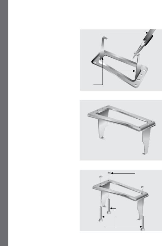
10.1. Foundation plate installation
When using a concrete foundation it is recommended that the foundation plate is welded to the rail/track of the gate using short length of flat bar, as in Figure
11. This makes it possible to complete the whole mechanical and electrical installation, without having to wait for the concrete to set. After completing the installation the concrete can be poured and the operator left in the Manual Mode until the concrete has set.
The foundation plate can either be set into a concrete foundation, as in Figures 12 to 18, or bolted down onto an existing concrete plinth as shown in Figure 19 and 20.
If the D2 Turbo is being used to replace a D3 gate operator, refer to Figures 22 to 27.
Foundation plate
Flat bar welded to foundation plate and rail
Option 1: Cast foundation plate into concrete
Bend the anchor brackets outwards as shown in Figure 13.
www.CentSys.com |
page 25 |
Gate rail
FIGURE 11
FIGURE 12
FIGURE 13
INSTALLATION OPERATOR
10 SECTION
OPERATOR INSTALLATION
Using a pair of long-nosed pliers, bend the ends of the anchor brackets at a 90° angle.
Long-nosed pliers
Anchor brackets
Fit the mounting bolts to the foundation plate and secure in place with nuts and washer.
SECTION 10
M10 washer 
M10 gearbox mounting bolts
page 26
FIGURE 14
FIGURE 15
M10 nut
FIGURE 16
www.CentSys.com
ENSURE THAT MOUNTING STUDS AND LOCKNUTS ARE FITTED BEFORE setting the foundation plate in
concrete or bolting to an existing plate.
Do not finish pouring concrete before the cables have been installed
– see next section Route Cable and Secure Foundation Plate on page 28.
300mm
400mm
mounting |
400mm |
|
|
|||||
M10 |
|
|
|
|
||||
gearbox |
|
|
|
|
|
|
|
|
bolts |
|
|
|
|
||||
|
|
|
|
|
|
|
|
|
|
|
|
|
|
|
|
|
|
Foundation |
|
|
|
40mm |
|
|
||
|
|
|
|
|||||
|
|
|
|
|||||
|
|
|
|
|
|
|
||
|
|
|
|
|
|
|||
plate |
|
|
|
|
||||
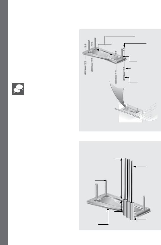
Option 2: Bolt foundation plate onto an existing concrete plinth
If bolting onto an existing concrete plinth, place the foundation plate down in the correct position and use the plate as a template for marking the rawlbolt holes.
Foundation  plate
plate
www.CentSys.com |
page 27 |
M10 gearbox mouting bolts
400mm
FIGURE 17
Cables
Conduit
FIGURE 18
FIGURE 19
INSTALLATION OPERATOR
10 SECTION
OPERATOR INSTALLATION
Fit the mounting studs to the foundation plate and secure in place with the stud locknuts.
Do not bend out the anchor brackets.
Route Cables and Secure
Foundation Plate
Route cables as determined in Section 7, Cabling Requirements.
Make sure that all cables and conduits protrude at least 400mm above the foundation plate once installed.
Securely concrete or bolt the foundation plate in position.
SECTION 10
M10 gearbox mounting bolts
Foundation plate
page 28
Anchor brackets
M10 nut
 M10 washer
M10 gearbox mounting bolts
Use two M12 plated nuts as spacers
M10 x 95 expansion stud
FIGURE 20
Cables
400mm
40mm
Conduit
FIGURE 21
www.CentSys.com
Option 3: Retrofitting D2 Turbo to an existing D3 foundation plate.
Grind off the existing mounting studs from the D3 foundation plate as shown in Figure 22.
Mounting
studs
Grinder |
|
D3 foundation |
|
|
|
|
|
plate |
FIGURE 22
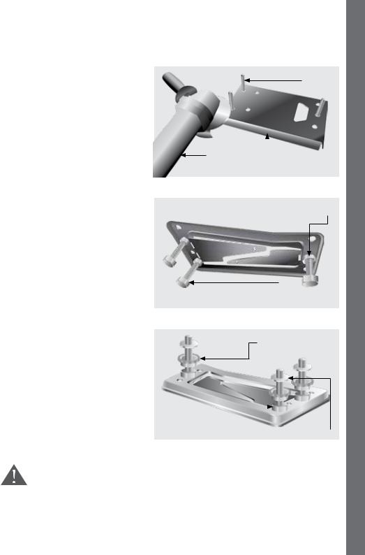
Fit the three mounting studs to the D2 Turbo foundation plate and secure in place using the stud locknuts supplied with this kit.
The half-height nuts should be used on the underside of the plate as shown in Figure 23, as these will later be used for height adjustment. However, if space allows
– i.e. there will be sufficient clearance between the rack and the pinion once the operator has been mounted – the orange height-adjustment nuts may be used
Stud locknut (M10 half-height nut)
 Mounting stud
FIGURE 23
Orange height-adjustment nuts
INSTALLATION OPERATOR
Stud locknut |
|
|
|
|
|
|
|
(M10 half-height nut) |
Washer |
||
|
|
|
|
|
|
|
FIGURE 24 |
Do not attempt to mount the gearbox without using either the half-height nuts or the orange jacking nuts as doing so will result in the gearbox being damaged when the hold-down nuts are tightened.
www.CentSys.com |
page 29 |
10 SECTION
OPERATOR INSTALLATION
Orange height-adjustment nuts
Use the supplied full-height hold-down nuts to temporarily secure the plate in place from above as shown in Figure 24.
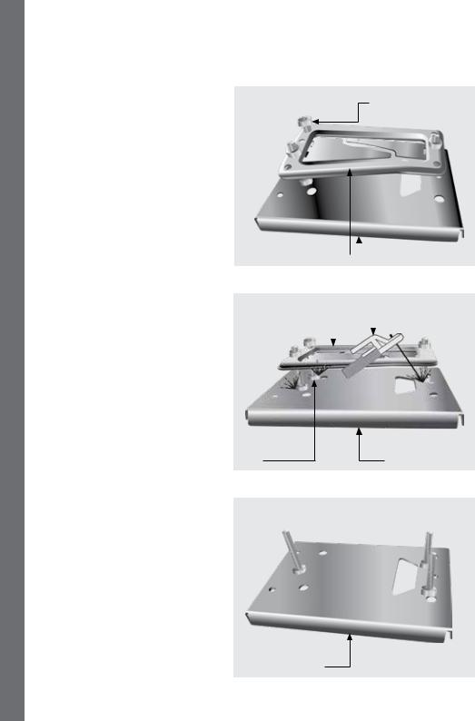
Place the D2 Turbo foundation plate onto the existing D3 plate in the optimum position.
D2 Turbo |
|
|
|
|
||||
foundation plate |
|
|
|
|
|
|
D3 foundation plate |
|
|
|
|
|
|
||||
|
|
|
|
|
|
|
|
FIGURE 25 |
D2 Turbo |
|
|
|
Weling machine |
||||
foundation plate |
|
|
|
|
|
|
||
|
|
|
|
|
|
|
|
|
|
|
|
|
|
|
|
|
|
SECTION 10
Carefully tack-weld the head of each individual mounting stud onto the D3 foundation plate.
Mounting |
D3 foundation plate |
stud |
FIGURE 26
Remove the hold-down nuts and lift the D2 Turbo foundation plate off of the mounting studs.
D3 foundation plate
FIGURE 27
page 30 |
www.CentSys.com |
 Loading...