

Page 1

Operation and
Maintenance
Manual
M0112246-02 (en-us)
November 2020
C9, C13 , C15, and C18 Generator Sets
RG3 1-UP (Generator Set)
S34 1-UP (Generator Set)
RG4 1-UP (Generator Set)
S35 1-UP (Generator Set)
RG5 1-UP (Generator Set)
S36 1-UP (Generator Set)
RE3 1-UP (Generator Set)
S44 1-UP (Generator Set)
RE4 1-UP (Generator Set)
S65 1-UP (Generator Set)
RK5 1-UP (Generator Set)
S37 1-UP (Generator Set)
Language: Original Instructions
PUBLICATIONS.CAT.COM
Page 2

i07966018
Important Safety Information
Most accidents that involve product operation, maintenance and repair are caused by failure to observe
basic safety rules or precautions. An accident can often be avoided by recognizing potentially hazardous
situations before an accident occurs. A person must be alert to potential hazards, including human factors
that can affect safety. This person should also have the necessary training, skills and tools to perform these
functions properly.
Improper operation, lubrication, maintenance or repair of this product can be dangerous and could
result in injury or death.
Do not operate or perform any lubrication, maintenance or repair on this product, until you verify
that you are authorized to perform this work, and have read and understood the operation,
lubrication, maintenance and repair information.
Safety precautions and warnings are provided in this manual and on the product. If these hazard warnings
are not heeded, bodily injury or death could occur to you or to other persons.
The hazards are identified by the “Safety Alert Symbol” and followed by a “Signal Word” such as
“DANGER”, “WARNING” or “CAUTION”. The Safety Alert “WARNING” label is shown below.
The meaning of this safety alert symbol is as follows:
Attention! Become Alert! Your Safety is Involved.
The message that appears under the warning explains the hazard and can be either written or pictorially
presented.
A non-exhaustive list of operations that may cause product damage are identified by “NOTICE” labels on
the product and in this publication.
Caterpillar cannot anticipate every possible circumstance that might involve a potential hazard.
The warnings in this publication and on the product are, therefore, not all inclusive. You must not
use this product in any manner different from that considered by this manual without first
satisfying yourself that you have considered all safety rules and precautions applicable to the
operation of the product in the location of use, including site-specific rules and precautions
applicable to the worksite. If a tool, procedure, work method or operating technique that is not
specifically recommended by Caterpillar is used, you must satisfy yourself that it is safe for you
and for others. You should also ensure that you are authorized to perform this work, and that the
product will not be damaged or become unsafe by the operation, lubrication, maintenance or repair
procedures that you intend to use.
The information, specifications, and illustrations in this publication are on the basis of information that was
available at the time that the publication was written. The specifications, torques, pressures,
measurements, adjustments, illustrations, and other items can change at any time. These changes can
affect the service that is given to the product. Obtain the complete and most current information before you
start any job. Cat dealers have the most current information available.
When replacement parts are required for this product Caterpillar recommends using original Caterpillar® replacement parts.
Other parts may not meet certain original equipment specifications.
NOTICE
When replacement parts are installed, the machine owner/user should ensure that the machine remains in compliance with all applicable requirements.
In the United States, the maintenance, replacement, or repair of the emission control devices and
systems may be performed by any repair establishment or individual of the owner's choosing.
Page 3

M0112246-02 3
Table of Contents
Table of Contents
Foreword ........................................................... 4
Safety Section
Safety Messages............................................... 6
General Hazard Information............................ 16
Burn Prevention............................................... 20
Fire Prevention and Explosion Prevention...... 20
Crushing Prevention and Cutting Prevention.. 22
Mounting and Dismounting ............................. 22
Before Starting Engine .................................... 22
Engine Starting................................................ 23
Engine Stopping .............................................. 23
Cold Weather Operation ................................. 74
Engine Stopping .............................................. 76
Maintenance Section
Refill Capacities............................................... 79
Maintenance Recommendations .................... 88
Maintenance Interval Schedule....................... 95
Warranty Section
Warranty Information ..................................... 143
Reference Information Section
Engine Ratings .............................................. 144
Customer Service.......................................... 145
Reference Materials ...................................... 147
Electrical System............................................. 23
Engine Electronics........................................... 24
Generator Isolating for Maintenance............... 24
Product Information Section
General Information ........................................ 26
Product Identification Information ................... 31
Operation Section
Lifting and Storage .......................................... 34
Installation ....................................................... 38
Features and Controls..................................... 42
Engine Diagnostics ......................................... 52
Engine Starting................................................ 59
Index Section
Index.............................................................. 150
Engine Operation ............................................ 64
Generator Operation ....................................... 66
Page 4

4 M0112246-02
Foreword
Foreword
California Proposition 65 Warning
Diesel engine exhaust and some of its
constituents are known to the State of
California to cause cancer, birth defects,
and other reproductive harm.
WARNING – This product can
expose you to chemicals
including ethylene glycol, which
is known to the State of California to
cause birth defects or other reproductive
harm. For more information go to:
www.P65Warnings.ca.gov
Do not ingest this chemical. Wash hands
after handling to avoid incidental
ingestion.
WARNING – This product can
expose you to chemicals
including lead and lead
compounds, which are known to the
State of California to cause cancer, birth
defects, or other reproductive harm. For
more information go to:
www.P65Warnings.ca.gov
Wash hands after handling components
that may contain lead.
Literature Information
This manual contains safety, operation instructions,
lubrication, and maintenance information. This
manual should be stored in or near the engine area in
a literature holder or literature storage area. Read,
study, and keep it with the literature and engine
information.
English is the primary language for all Cat
publications. The English used facilitates translation
and consistency in electronic media delivery.
Some photographs or illustrations in this manual
show details or attachments that may be different
from your engine. Guards and covers may have been
removed for illustrative purposes. Continuing
improvement and advancement of product design
may have caused changes to your engine which are
not included in this manual Whenever a question
arises regarding your engine, or this manual, please
consult with your Cat dealer for the latest available
information.
Safety
This safety section lists basic safety precautions. In
addition, this section identifies hazardous, warning
situations. Read and understand the basic
precautions listed in the safety section before
operating or performing lubrication, maintenance,
and repair on this product.
Operation
Operating techniques outlined in this manual are
basic. They assist with developing the skills and
techniques required to operate the engine more
efficiently and economically. Skill and techniques
develop as the operator gains knowledge of the
engine and its capabilities.
The operation section is a reference for operators.
Photographs and illustrations guide the operator
through procedures of inspecting, starting, operating,
and stopping the engine. This section also includes a
discussion of electronic diagnostic information.
Maintenance
The maintenance section is a guide to engine care.
The illustrated, step-by-step instructions are grouped
by fuel consumption, service hours and/or calendar
time maintenance intervals. Items in the maintenance
schedule are referenced to detailed instructions that
follow.
Use fuel consumption or service hours to determine
intervals. Calendar intervals shown (daily, annually,
etc.) may be used instead of service meter intervals if
they provide more convenient schedules and
approximate the indicated service meter reading.
Recommended service should be performed at the
appropriate intervals as indicated in the Maintenance
Interval Schedule. The actual operating environment
of the engine also governs the Maintenance Interval
Schedule. Therefore, under severe, dusty, wet, or
freezing cold operating conditions, more frequent
lubrication, and maintenance than is specified in the
Maintenance Interval Schedule may be necessary.
Page 5

M0112246-02
The maintenance schedule items are organized for a
preventive maintenance management program. If the
preventive maintenance program is followed, a
periodic tune-up is not required. The implementation
of a preventive maintenance management program
should minimize operating costs through cost
avoidances resulting from reductions in unscheduled
downtime and failures.
Maintenance Intervals
Perform maintenance on items at multiples of the
original requirement. Each level and/or individual
items in each level should be shifted ahead or back
depending upon your specific maintenance practices,
operation, and application. We recommend that the
maintenance schedules be reproduced and
displayed near the engine as a convenient reminder.
We also recommend that a maintenance record be
maintained as part of the engine's permanent record.
See the section in the Operation and Maintenance
Manual, “Maintenance Records” for information
regarding documents that are accepted as proof of
maintenance or repair. Your authorized Cat dealer
can assist you in adjusting your maintenance
schedule to meet the needs of your operating
environment.
5
Foreword
Overhaul
Major engine overhaul details are not covered in the
Operation and Maintenance Manual except for the
interval and the maintenance items in that interval.
Major repairs are best left to trained personnel or an
authorized Cat dealer. Your Cat dealer offers various
options regarding overhaul programs. If you
experience a major engine failure, there are also
numerous after failure overhaul options available
from your Cat dealer. Consult with your dealer for
information regarding these options.
Page 6

6 M0112246-02
Safety Section
Safety Messages
Safety Section
i07942225
Safety Messages
SMCS Code: 1000; 7405
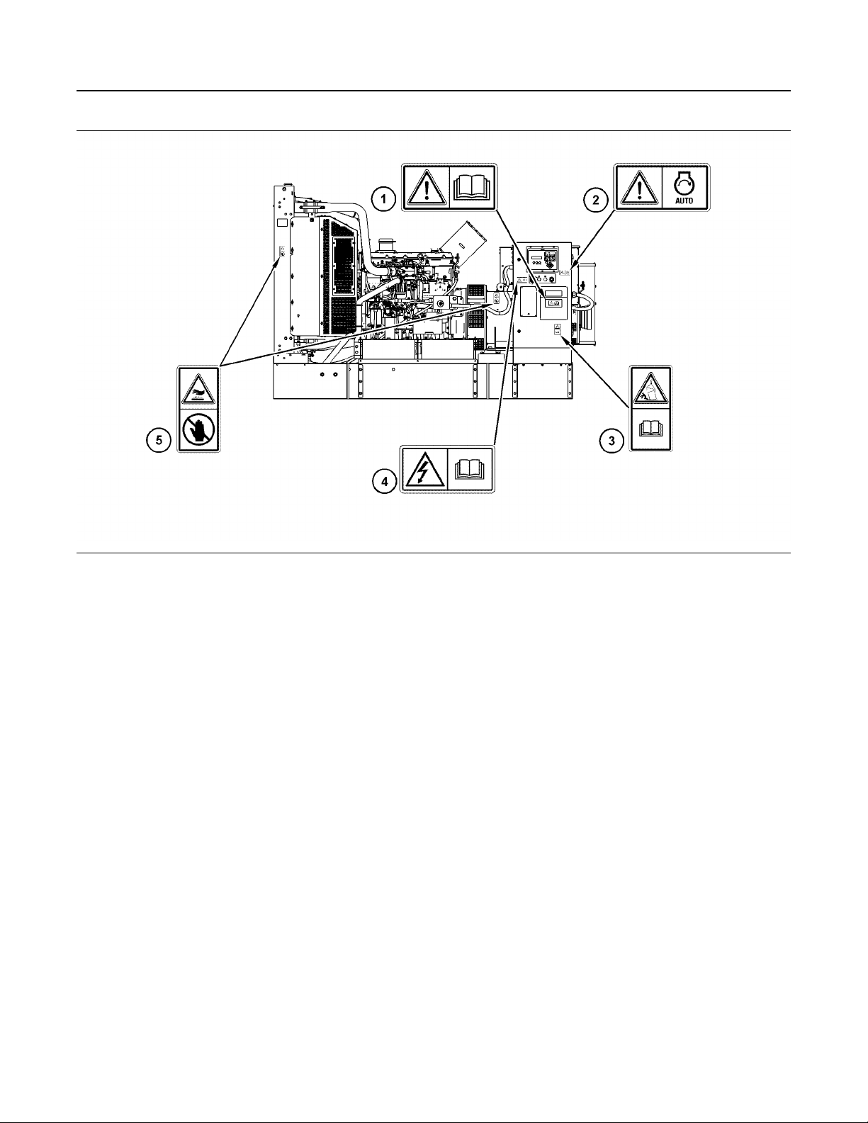
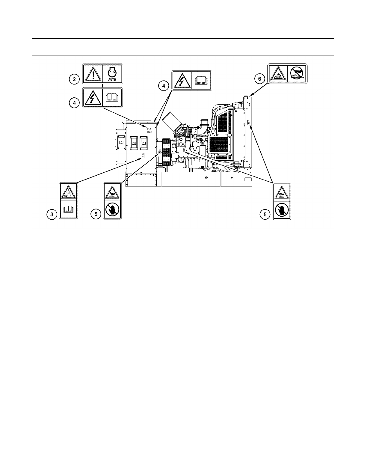
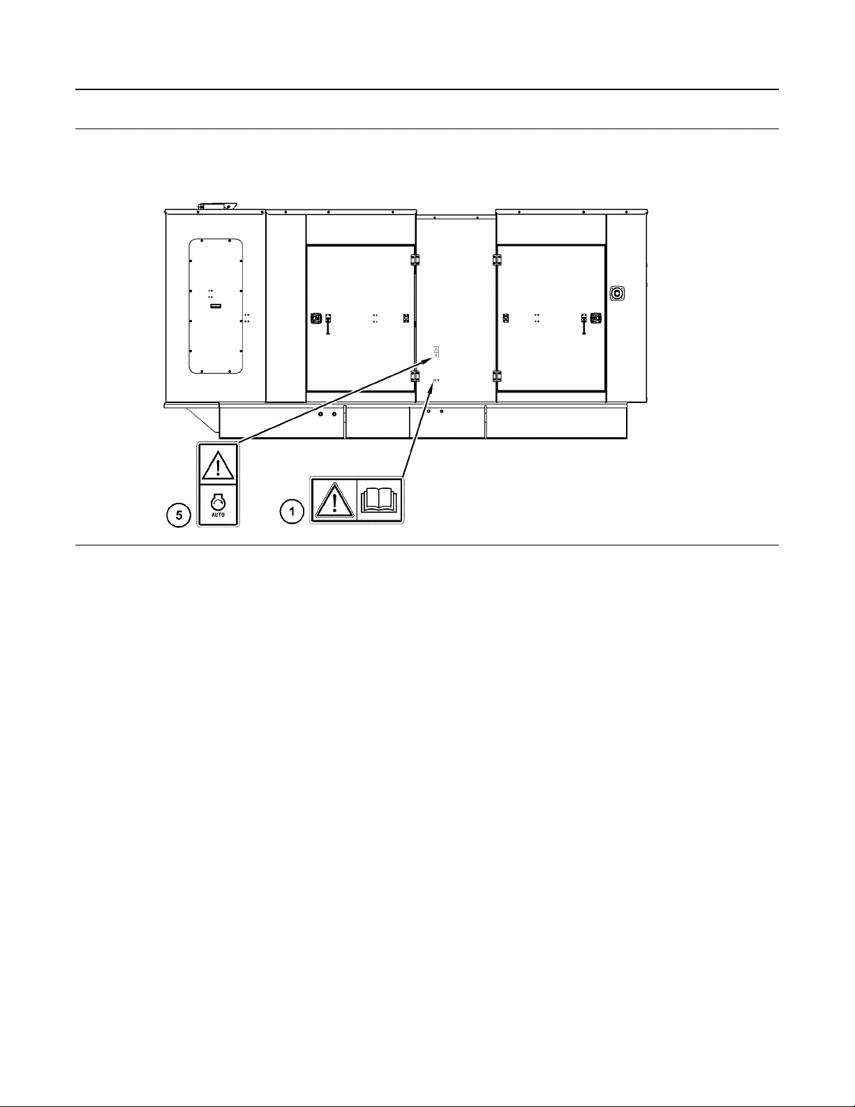
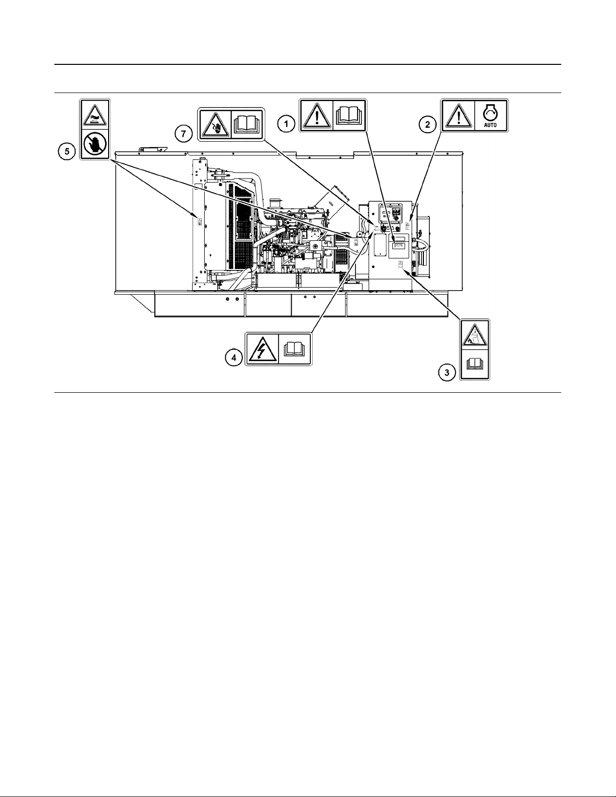
There may be several specific safety messages on
your generator set. The exact location and a
description of the safety messages are reviewed in
this section. Become familiar with all safety
messages.
Ensure that all the safety messages are legible.
Clean the safety messages or replace the safety
messages if the words cannot be read or if the
illustrations are not visible. Use a cloth, water, and
soap to clean the safety messages. Do not use
solvents, gasoline, or other harsh chemicals.
Solvents, gasoline, or harsh chemicals could loosen
the adhesive that secures the safety messages. The
safety messages that are loosened could drop off the
engine.
Replace any safety message that is damaged or
missing. If a safety message is attached to a part of
the engine that is replaced, install a new safety
message on the replacement part. Your Caterpillar
dealer can provide new safety messages.
Electrical backfeed into a utility's distribution
system can cause property damage, severe injury, or death. Do not connect generator to a building's main switch has been used to isolate the
building from the utility power system. For permanent installations, connection shall only be a
double throw switch as to isolate the building
from a utility power system. Consult a qualified
technician for proper use and installation. Comply with all applicable laws and electrical codes.
Page 7
M0112246-02
7
Safety Section
Safety Messages
Illustration 1 g03686209
Left side (open generator set)(typical example)
Page 8
8 M0112246-02
Safety Section
Safety Messages
Illustration 2 g03686283
Right side (open generator set)(typical example)
Page 9
M0112246-02 9
Safety Section
Safety Messages
Illustration 3 g03693570
Left side view of the enclosure (typical example)
Page 10
10 M0112246-02
Safety Section
Safety Messages
Illustration 4 g03686037
Left side view of the enclosed generator set (typical example)
Page 11
M0112246-02 11
Safety Section
Safety Messages
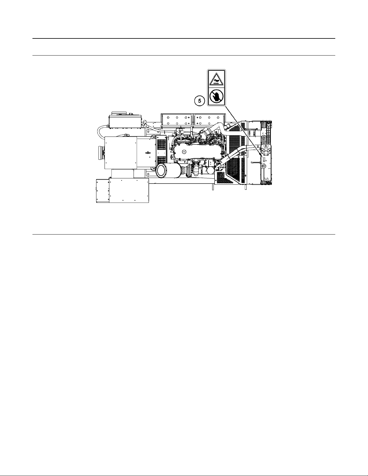
Illustration 5 g03686053
View of the top of the generator set (typical example)
Page 12
12 M0112246-02
Safety Section
Safety Messages
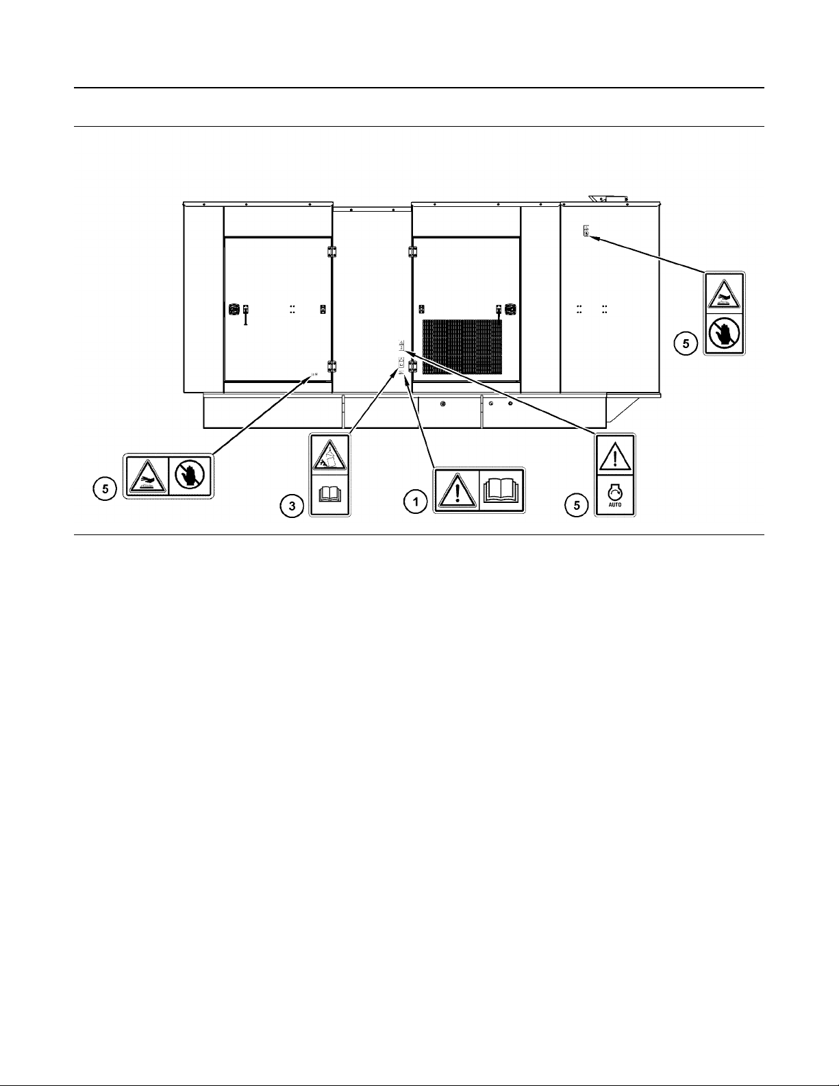
Illustration 6 g03686194
Right side view of the generator set enclosure (typical example)
Page 13
M0112246-02 13
Safety Section
Safety Messages
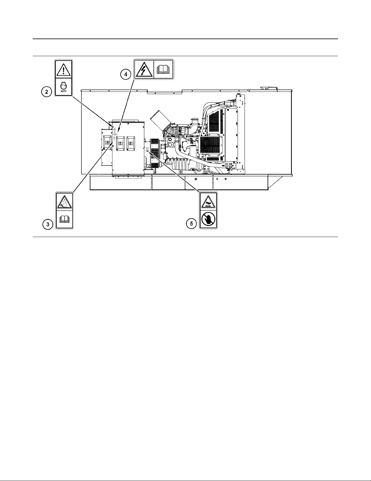
Illustration 7 g03693658
Right side view of the enclosed generator set (typical example)
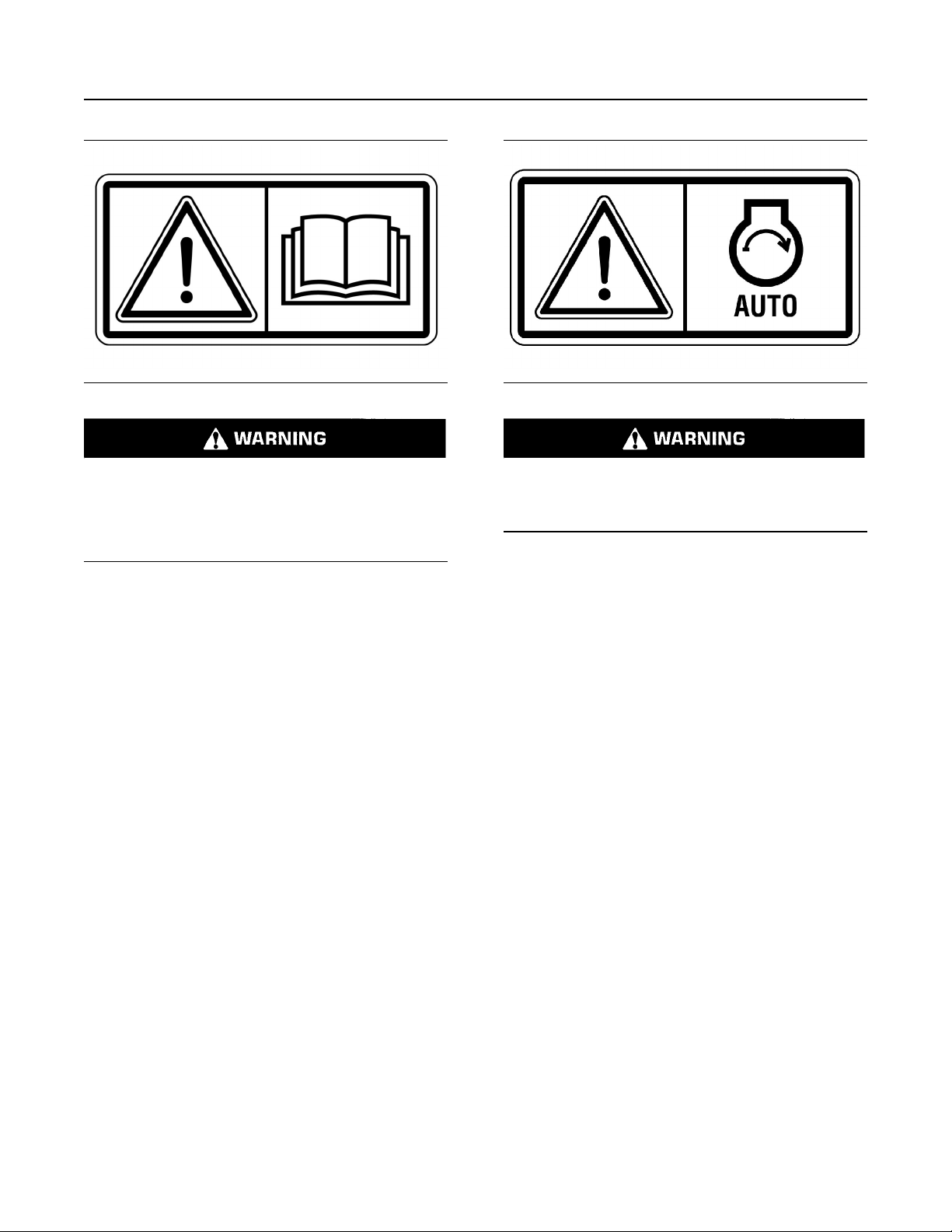
Universal Warning (1)
The universal safety message is on the terminal box,
and on both sides of the enclosure.
Page 14
14 M0112246-02
Safety Section
Safety Messages
Illustration 8 g01370904
Do not operate or work on this equipment unless
you have read and understand the instructions
and warnings in the Operation and Maintenance
Manuals. Failure to follow the instructions or
heed the warnings could result in serious injury
or death.
Automatic Starting (2)
The safety message for automatic starting is on both
sides of the generator, on the sides of the terminal
box, and on both sides of the enclosure.
Illustration 9 g01392484
When the engine is in the AUTOMATIC mode, the
engine can start at any moment. To avoid personal injury, always remain clear of the the engine
when the engine is in the AUTOMATIC mode.
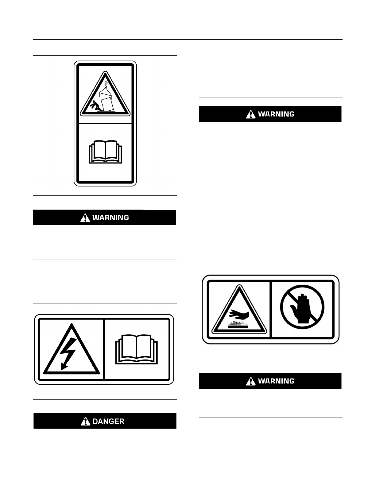
Crush Falling Object (3)
The safety message concerning falling objects is on
both sides of the terminal box, and both sides of the
enclosure.
Page 15
M0112246-02 15
Safety Section
Safety Messages
DANGER: Shock/Electrocution Hazard-Do not
operate this equipment or work on this
equipment unless you have read and understand
the instructions and warnings in the Operation
and Maintenance Manual. Failure to follow the
instructions or heed the warnings will result in
serious injury or death.
Do not connect generator to a utility electrical
distribution system unless it is isolated from the
system. Electrical feedback into the distribution
system can occur and could cause personal injury or death.
Open and secure main distribution system
switch, or if the connection is permanent, install
a double throw transfer switch to prevent electrical feedback. Some generators are specifically
approved by a utility to run in parallel with the
Illustration 10 g01433231
distribution system and isolation may not be required. Always check with your utility as to the
applicable circumstances.
Crushing hazard! Read and understand the instructions and warnings in the Operation and
Maintenance manual. Failure to follow the in-
structions or heed the warnings could cause serious injury or death.
Electrocution (4)
The safety message is on both sides of the terminal
box, and on both sides of the enclosure.
Illustration 11 g03430411
Hot Surface (5)
The safety message for hot surfaces is on the top of
the enclosure group, on both sides of the radiator,
and on both sides of the enclosure.
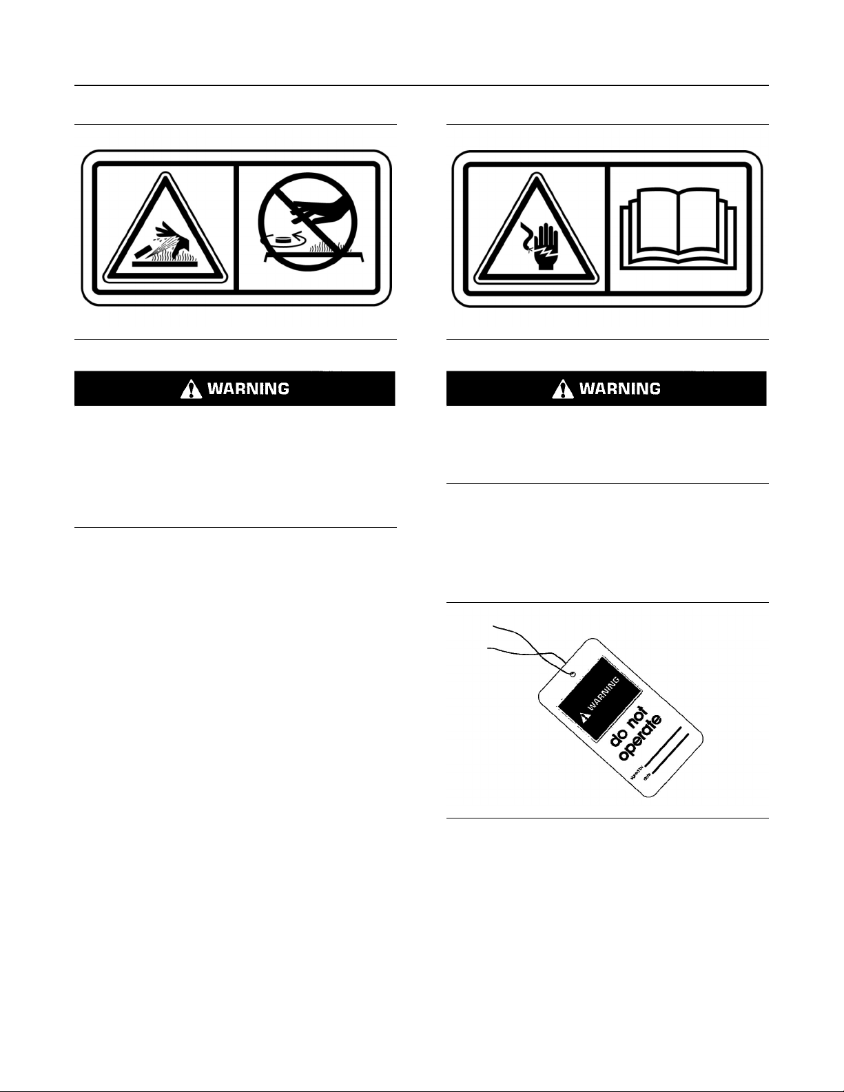
Illustration 12 g01372256
Hot parts or hot components can cause burns or
personal injury. Do not allow hot parts or components to contact your skin. Use protective clothing or protective equipment to protect your skin.
Hot Fluid Under Pressure (6)
The safety message about hot fluid under pressure is
located near the radiator cap.
Page 16
16 M0112246-02
Safety Section
General Hazard Information
Illustration 13 g01371640
Pressurized system! Hot coolant can cause serious burns, injury or death. To open the cooling
system filler cap, stop the engine and wait until
the cooling system components are cool. Loosen
the cooling system pressure cap slowly in order
to relieve the pressure. Read and understand the
Operation and Maintenance Manual before performing any cooling system maintenance.
Electrical Shock (7)
The safety message for electrical shock is on the side
of the enclosure.
Illustration 14 g01372247
WARNING! Shock/Electrocution Hazard! Read
and understand the instructions and warnings in
the Operation and Maintenance Manual. Failure
to follow the instructions or heed the warnings
could cause serious injury or death.
i06300340
General Hazard Information
SMCS Code: 1000; 4450; 7405
Illustration 15 g03838041
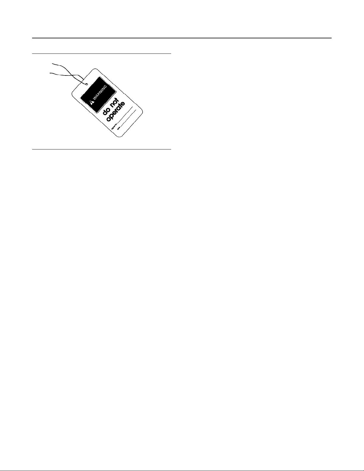
Attach a “Do Not Operate” warning tag to the start
switch or controls before the engine is serviced or
repaired. These warning tags (Special Instruction,
SEHS7332) are available from your Cat dealer.
Attach the warning tags to the engine and to each
operator control station. When appropriate,
disconnect the starting controls.
Do not allow unauthorized personnel on the engine,
or around the engine when the engine is being
serviced.
Page 17
M0112246-02 17
Safety Section
General Hazard Information
Cautiously remove the following parts. To help
prevent spraying or splashing of pressurized fluids,
hold a rag over the part that is being removed.
• Filler caps
• Grease fittings
• Pressure taps
• Breathers
• Drain plugs
Use caution when cover plates are removed.
Gradually loosen, but do not remove the last two
bolts or nuts that are located at opposite ends of the
cover plate or the device. Before removing the last
two bolts or nuts, pry the cover loose in order to
relieve any spring pressure or other pressure.
• The protective locks or the controls are in the
applied position.
• Disconnect the batteries when maintenance is
performed or when the electrical system is
serviced. Disconnect the battery ground leads.
Tape the leads in order to help prevent sparks.
• When starting a new engine, make provisions to
stop the engine if an overspeed occurs. If an
engine has not been started since service has
been performed, make provisions to stop the
engine if an overspeed occurs. Shutting down the
engine may be accomplished by shutting off the
fuel supply and/or the air supply to the engine.
• Do not attempt any repairs that are not
understood. Use the proper tools. Replace any
equipment that is damaged or repair the
equipment.
• Start the engine with the operator controls. Never
short across the starting motor terminals or the
batteries. This method of starting the engine could
bypass the engine neutral start system and/or the
electrical system could be damaged.
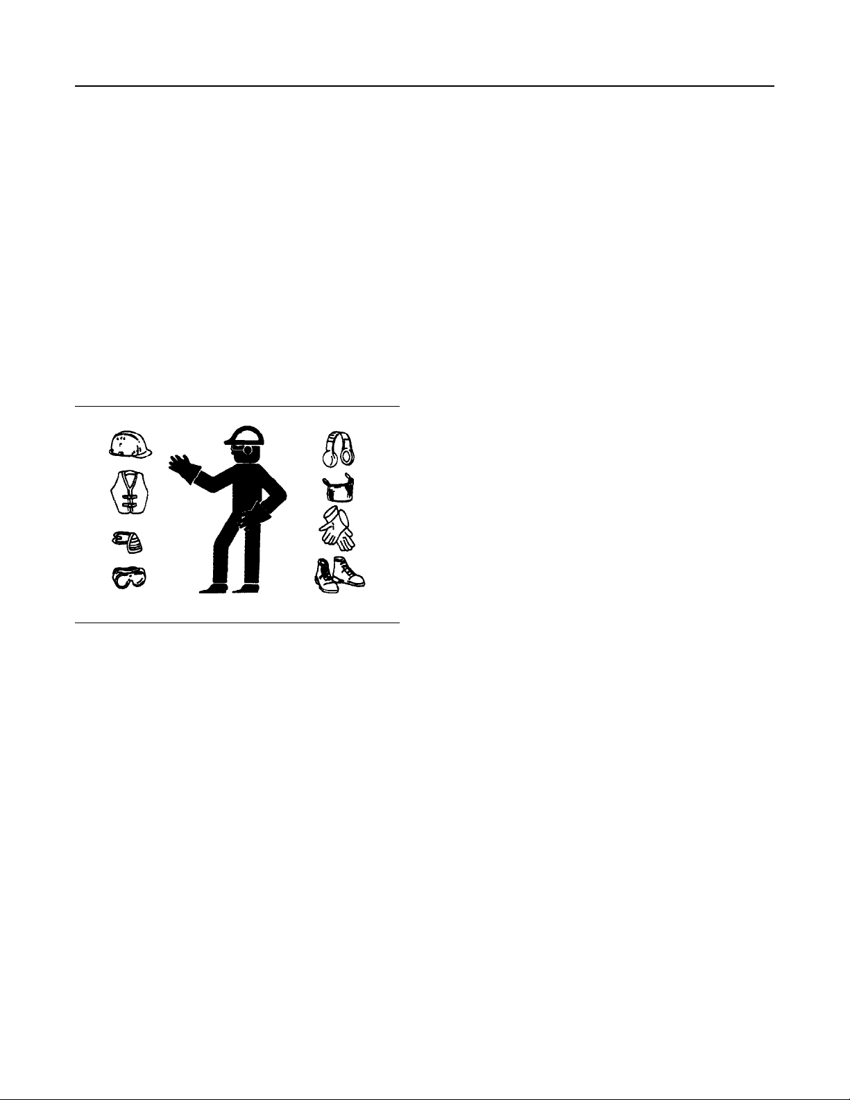
Illustration 16 g00702020
• Wear a hard hat, protective glasses, and other
protective equipment, as required.
• When work is performed around an engine that is
operating, wear protective devices for ears in
order to help prevent damage to hearing.
• Do not wear loose clothing or jewelry that can
snag on controls or on other parts of the engine.
• Ensure that all protective guards and all covers
are secured in place on the engine.
• Never put maintenance fluids into glass
containers. Glass containers can break.
• Use all cleaning solutions with care.
• Report all necessary repairs.
Pressurized Air and Water
Pressurized air and/or water can cause debris and/or
hot water to be blown out which could result in
personal injury.
The maximum air pressure for cleaning purposes
must be reduced to 205 kPa (30 psi) when the air
nozzle is deadheaded and used with effective chip
guarding (if applicable) and personal protective
equipment. The maximum water pressure for
cleaning purposes must be below 275 kPa (40 psi).
When pressurized air and/or pressurized water is
used for cleaning, wear protective clothing, protective
shoes, and eye protection. Eye protection includes
goggles or a protective face shield. Always wear eye
protection for cleaning the cooling system.
Unless other instructions are provided, perform
the maintenance under the following conditions:
• The engine is stopped. Ensure that the engine
cannot be started.
Page 18
18 M0112246-02
Safety Section
General Hazard Information
Avoid direct spraying of water on electrical
connectors, connections, and components. When
using air for cleaning, allow the machine to cool to
reduce the possibility of fine debris igniting when
redeposited on hot surfaces.
Fluid Penetration
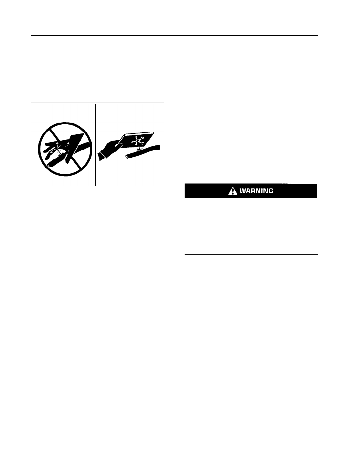
Illustration 17 g00687600
Always use a board or cardboard when you check for
a leak. Leaking fluid that is under pressure can
penetrate body tissue. Fluid penetration can cause
serious injury and possible death. A pin hole leak can
cause severe injury. If fluid is injected into your skin,
you must get treatment immediately. Seek treatment
from a doctor that is familiar with this type of injury.
Containing Fluid Spillage
Static Electricity Hazard when
Fueling with Ultra-low Sulfur Diesel
Fuel
The removal of sulfur and other compounds in ultralow sulfur diesel fuel (ULSD fuel) decreases the
conductivity of ULSD and increases the ability of
ULSD to store static charge. Refineries may have
treated the fuel with a static dissipating additive.
Many factors can reduce the effectiveness of the
additive over time. Static charges can build up in
ULSD fuel while the fuel is flowing through fuel
delivery systems. Static electricity discharge when
combustible vapors are present could result in a fire
or explosion. Ensure that the entire system used to
refuel your machine (fuel supply tank, transfer pump,
transfer hose, nozzle, and others) is properly
grounded and bonded. Consult with your fuel or fuel
system supplier to ensure that the delivery system
complies with fueling standards for proper grounding
and bonding.
Avoid static electricity risk when fueling. Ultralow sulfur diesel fuel (ULSD fuel) poses a greater
static ignition hazard than earlier diesel formulations with a higher sulfur contents. Avoid death
or serious injury from fire or explosion. Consult
with your fuel or fuel system supplier to ensure
the delivery system is in compliance with fueling
standards for proper grounding and bonding
practices.
Care must be taken to ensure that fluids are con-
NOTICE
tained during performance of inspection, maintenance, testing, adjusting, and repair of the product.
Be prepared to collect the fluid with suitable containers before opening any compartment or disassembling any component containing fluids.
Refer to Special Publication, NENG2500, “Cat Dealer
Service Tool Catalog” or refer to Special Publication,
PECJ0003, “Cat Shop Supplies and Tools Catalog”
for tools and supplies suitable to collect and contain
fluids on Cat products.
Dispose of all fluids according to local regulations
and mandates.
Lines, Tubes, and Hoses
Do not bend or strike high-pressure lines. Do not
install lines, tubes, or hoses that are damaged.
Repair any fuel lines, oil lines, tubes, or hoses that
are loose or damaged. Leaks can cause fires.
Inspect all lines, tubes, and hoses carefully. Do not
use bare hands to check for leaks. Always use a
board or cardboard for checking engine components
for leaks. Tighten all connections to the
recommended torque.
Check for the following conditions:
• End fittings that are damaged or leaking
• Outer covering that is chafed or cut
• Wire that is exposed in reinforced hose
• Outer covering that is ballooning locally
• Flexible part of the hose that is kinked or crushed
• Armoring that is embedded in the outer covering
Page 19

M0112246-02 19
Safety Section
General Hazard Information
Ensure that all of the clamps, the guards, and the
heat shields are installed correctly. Correct
installation of these components will help to prevent
these effects: vibration, rubbing against other parts
and excessive heat during operation.
Inhalation
Illustration 18 g02159053
Exhaust
Use caution. Exhaust fumes can be hazardous to
your health. If you operate the equipment in an
enclosed area, adequate ventilation is necessary.
Asbestos Information
Cat equipment and replacement parts that are
shipped from Caterpillar are asbestos free.
Caterpillar recommends the use of only genuine Cat
replacement parts. Use the following guidelines when
you handle any replacement parts that contain
asbestos or when you handle asbestos debris.
• A vacuum cleaner that is equipped with a high
efficiency particulate air filter (HEPA) can also be
used.
• Use exhaust ventilation on permanent machining
jobs.
• Wear an approved respirator if there is no other
way to control the dust.
• Comply with applicable rules and regulations for
the work place. In the United States, use
Occupational Safety and Health Administration
(OSHA) requirements. These OSHA requirements
can be found in “29 CFR 1910.1001”.
• Obey environmental regulations for the disposal of
asbestos.
• Stay away from areas that might have asbestos
particles in the air.
Softwrap
Keep the engine room ventilation operating at full
capacity. Wear a particulate respirator that has been
approved by the National Institute of Occupational
Safety and Health (NIOSH). Wear appropriate
protective clothing in order to minimize direct contact.
Use good hygiene practices and wash hands
thoroughly after handling Softwrap material. Do not
smoke until washing hands thoroughly after handling
Softwrap material. Clean up debris with a vacuum or
by wet sweeping. Do not use pressurized air to clean
up debris.
Use caution. Avoid inhaling dust that might be
generated when you handle components that contain
asbestos fibers. Inhaling this dust can be hazardous
to your health. The components that may contain
asbestos fibers are brake pads, brake bands, lining
material, clutch plates, and some gaskets. The
asbestos that is used in these components is bound
in a resin or sealed in some way. Normal handling is
not hazardous unless airborne dust that contains
asbestos is generated.
If dust that may contain asbestos is present, there
are several guidelines that should be followed:
• Never use compressed air for cleaning.
• Avoid brushing materials that contain asbestos.
• Avoid grinding materials that contain asbestos.
• Use a wet method in order to clean up asbestos
materials.
Page 20
20 M0112246-02
Safety Section
Burn Prevention
Reference: The applicable material safety data
sheets can be found at the following web site by
searching using part number or the name:
https://catmsds.cat.com/MSDSSearch/servlet/
cat.cis.ecs.
msdsSearch.controller.
UserIdentificationDisplayServlet
Dispose of Waste Properly
Illustration 19 g00706404
Improperly disposing of waste can threaten the
environment. Potentially harmful fluids should be
disposed of according to local regulations.
Ensure that the filler cap is cool before removing the
filler cap. The filler cap must be cool enough to touch
with a bare hand. Remove the filler cap slowly to
relieve pressure.
Cooling system conditioner contains alkali. Alkali can
cause personal injury. Do not allow alkali to contact
the skin, the eyes, or the mouth.
Oils
Hot oil and hot lubricating components can cause
personal injury. Do not allow hot oil to contact the
skin. Also, do not allow hot components to contact
the skin.
Batteries
Electrolyte is an acid. Electrolyte can cause personal
injury. Do not allow electrolyte to contact the skin or
the eyes. Always wear protective glasses for
servicing batteries. Wash hands after touching the
batteries and connectors. Use of gloves is
recommended.
i08203814
Fire Prevention and Explosion
Prevention
SMCS Code: 1000; 4450; 7405
Always use leakproof containers when you drain
fluids. Do not pour waste onto the ground, down a
drain, or into any source of water.
i08162288
Burn Prevention
SMCS Code: 1000; 4450; 7405
Do not touch any part of an operating engine. Allow
the engine to cool before any maintenance is
performed on the engine. Relieve all pressure in the
air system, hydraulic system, lubrication system, fuel
system, and cooling system before any lines, fittings,
or related items are disconnected.
Coolant
When the engine is at operating temperature, the
engine coolant is hot. The coolant is also under
pressure. The radiator and all lines to the heaters or
to the engine contain hot coolant.
Any contact with hot coolant or with steam can cause
severe burns. Allow cooling system components to
cool before the cooling system is drained.
Check that the coolant level after the engine has
stopped and the engine has been allowed to cool.
Illustration 20 g00704000
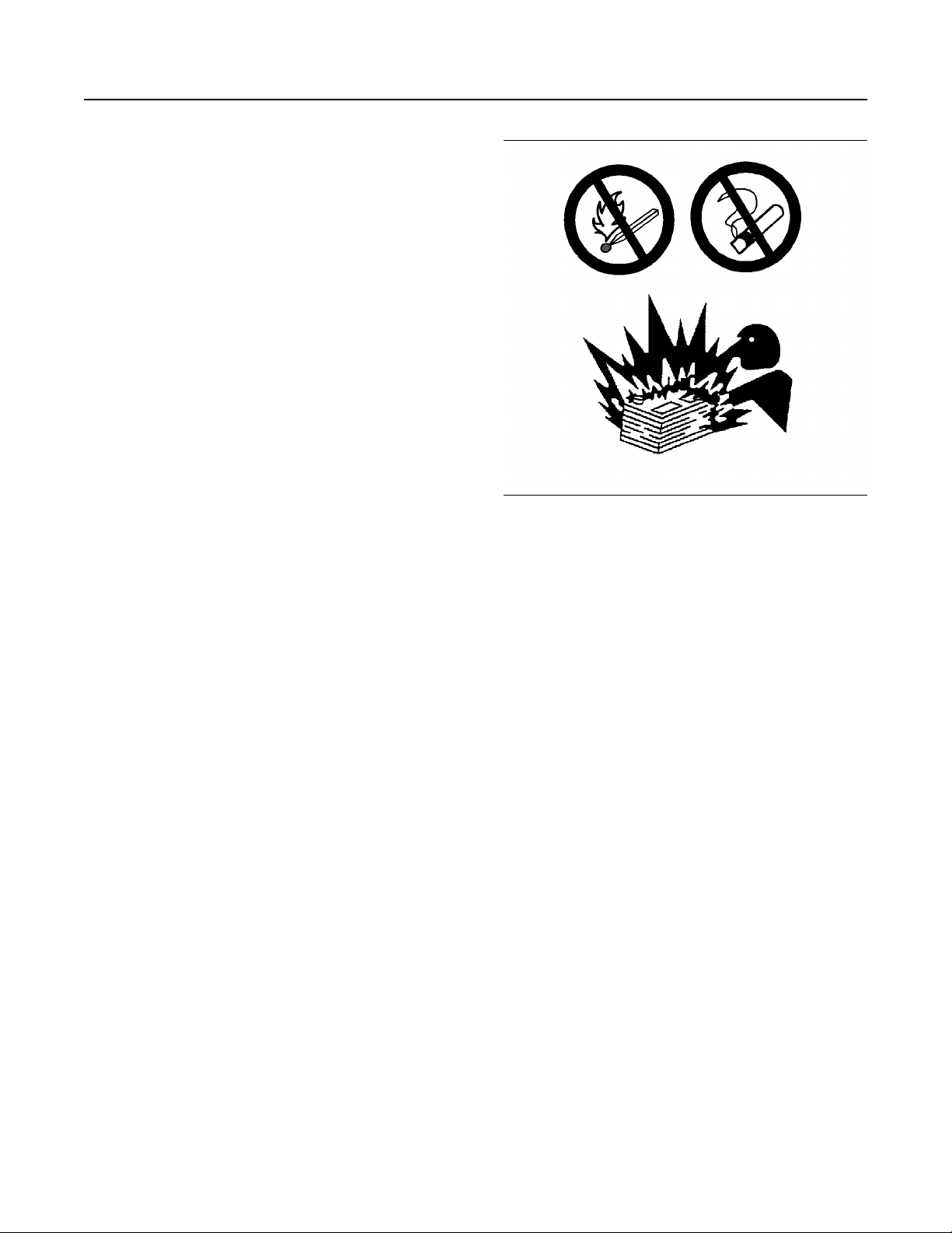
All fuels, most lubricants, and some coolant mixtures
are flammable.
Flammable fluids that are leaking or spilled onto hot
surfaces or onto electrical components can cause a
fire. Fire may cause personal injury and property
damage.
Flash fires may result if the covers for the engine
crankcase are removed within 15 minutes after an
emergency shutdown.
Page 21
M0112246-02 21
Safety Section
Fire Prevention and Explosion Prevention
Determine whether the engine will be operated in an
environment that allows combustible gases to be
drawn into the air inlet system. These gases could
cause the engine to overspeed. Personal injury,
property damage, or engine damage could result.
If the application involves the presence of
combustible gases, consult your Cat dealer for
additional information about suitable protection
devices.
Remove all flammable materials such as fuel, oil, and
debris from the engine. Do not allow any flammable
materials to accumulate on the engine.
Store fuels and lubricants in properly marked
containers away from unauthorized persons. Store
oily rags and any flammable materials in protective
containers. Do not smoke in areas that are used for
storing flammable materials.
Do not expose the engine to any flame.
Exhaust shields (if equipped) protect hot exhaust
components from oil or fuel spray in a line, a hose, or
a seal failure. Exhaust shields must be installed
correctly.
Do not weld on lines or tanks that contain flammable
fluids. Do not flame cut lines that contain flammable
fluid. Clean any such lines thoroughly with a
nonflammable solvent prior to welding or flame
cutting.
Wiring must be kept in good condition. Ensure that all
electrical wires are properly routed and securely
attached. Check all electrical wires daily. Repair any
wires that are loose or frayed before you operate the
engine. Clean all electrical connections and tighten
all electrical connections.
Eliminate all wiring that is unattached or
unnecessary. Do not use any wires or cables that are
smaller than the recommended gauge. Do not
bypass any fuses and/or circuit breakers.
Arcing or sparking could cause a fire. Secure
connections, recommended wiring, and properly
maintained battery cables will help to prevent arcing
or sparking.
Inspect all lines and hoses for wear or for
deterioration. Properly route all hoses. The lines and
hoses must have adequate support and secure
clamps. Tighten all connections to the recommended
torque. Leaks can cause fires.
Properly install all oil filters and fuel filters. The filter
housings must be tightened to the proper torque.
Illustration 21 g02298225
Gases from a battery can explode. Keep any open
flames or sparks away from the top of a battery. Do
not smoke in battery charging areas.
Never check the battery charge by placing a metal
object across the terminal posts. Use a voltmeter or a
hydrometer.
Improper jumper cable connections can cause an
explosion that can result in injury. Refer to the
Operation Section of this manual for specific
instructions.
Do not charge a frozen battery. Charging a frozen
battery may cause an explosion.
The batteries must be kept clean. The covers (if
equipped) must be kept on the cells. Use the
recommended cables, connections, and battery box
covers when the engine is operated.
Fire Extinguisher
Make sure that a fire extinguisher is available. Be
familiar with the operation of the fire extinguisher.
Inspect the fire extinguisher and service the fire
extinguisher regularly. Obey the recommendations
on the instruction plate.
Lines, Tubes, and Hoses
Do not bend high-pressure lines. Do not strike highpressure lines. Do not install any lines that are bent
or damaged.
Repair any lines that are loose or damaged. Leaks
can cause fires. Consult your Cat dealer for repair or
for replacement parts.
Page 22

22 M0112246-02
Safety Section
Crushing Prevention and Cutting Prevention
Check lines, tubes, and hoses carefully. Do not use
your bare hand to check for leaks. Use a board or
cardboard to check for leaks. Tighten all connections
to the recommended torque.
Replace the parts if any of the following conditions
are present:
• End fittings are damaged or leaking.
• Outer coverings are chafed or cut.
• Wires are exposed.
• Outer coverings are ballooning.
• Flexible parts of the hoses are kinked.
• Outer covers have embedded armoring.
• End fittings are displaced.
Make sure that all clamps, guards, and heat shields
are installed correctly to prevent vibration, rubbing
against other parts, and excessive heat.
i08162291
Crushing Prevention and
Cutting Prevention
SMCS Code: 1000; 4450; 7405
Mount the engine and dismount the engine only at
locations that have steps and/or handholds. Do not
climb on the engine, and do not jump off the engine.
Face the engine to mount the engine or dismount the
engine. With your feet and hands, always maintain a
three-point contact with the steps and designated
handholds. Do not use any controls as handholds.
Do not stand on components which cannot support
your weight. Use an adequate ladder or use a work
platform. Secure the climbing equipment so that the
equipment will not move.
Do not carry tools or supplies when you mount the
engine or when you dismount the engine. Use a hand
line to raise and lower tools or supplies.
i08258438
Before Starting Engine
SMCS Code: 1000
NOTICE
For initial start-up of a new or rebuilt engine, and for
start-up of an engine that has been serviced, make
provision to shut the engine off should an overspeed
occur. This may be accomplished by shutting off the
air and/or fuel supply to the engine.
Support the component properly when work beneath
the component is performed.
Unless other maintenance instructions are provided,
never attempt adjustments while the engine is
running.
Stay clear of all rotating parts and of all moving parts.
Leave the guards in place until maintenance is
performed. After the maintenance is performed,
reinstall the guards.
Keep objects away from moving fan blades. The fan
blades will throw objects or cut objects.
When objects are struck, wear protective glasses to
avoid injury to the eyes.
Chips or other debris may fly off objects when objects
are struck. Before objects are struck, ensure that no
one will be injured by flying debris.
i08159517
Mounting and Dismounting
SMCS Code: 1000; 4450; 7405
Inspect the steps, the handholds, and the work area
before mounting the engine. Keep these items clean
and keep these items in good repair.
Engine exhaust contains products of combustion
which may be harmful to your health. Always
start and operate the engine in a well ventilated
area and, if in an enclosed area, vent the exhaust
to the outside.
Inspect the engine for potential hazards.
Do not start the engine if there is a “DO NOT
OPERATE” warning tag or similar warning tag
attached to the start switch. Do not move any of the
controls if there is a “DO NOT OPERATE” warning
tag or similar warning tag attached to the controls.
Before starting the engine, ensure that no one is on,
underneath, or close to the engine. Ensure that the
area is free of personnel.
If equipped, ensure that the lighting system for the
engine is suitable for the conditions. Ensure that all
lights work properly, if equipped.
All protective guards and all protective covers must
be installed if the engine must be started to perform
service procedures. To help prevent an accident that
is caused by parts in rotation, work around the parts
carefully.
Page 23

M0112246-02 23
Safety Section
Engine Starting
Do not bypass the automatic shutoff circuits. Do not
disable the automatic shutoff circuits. The circuits are
provided to help prevent personal injury. The circuits
are also provided to help prevent engine damage.
See the Service Manual for repairs and for
adjustments.
i08193936
Engine Starting
SMCS Code: 1000
If a warning tag is attached to the engine start switch,
DO NOT start the engine. If a warning tag is attached
to the controls, DO NOT move the controls. Consult
with the person that attached the warning tag before
the engine is started.
All protective guards and all protective covers must
be installed if the engine must be started to perform
service procedures. To help prevent an accident that
is caused by parts in rotation, work around the parts
carefully.
Start the engine from the operator compartment or
from the engine start switch.
Always start the engine according to the procedure
that is described in this Operation and Maintenance
Manual, “Engine Starting” topic (Operation Section).
Knowing the correct procedure will help to prevent
major damage to the engine components. Knowing
the procedure will also help to prevent personal
injury.
To ensure that the jacket water heater (if equipped)
and/or the lube oil heater (if equipped) is working
properly, check the water temperature gauge and the
oil temperature gauge during the heater operation.
Engine exhaust contains products of combustion that
can be harmful to your health. Always start the
engine and operate the engine in a well-ventilated
area. If the engine is started in an enclosed area,
vent the engine exhaust to the outside.
Ether
Ether is poisonous and flammable.
Do not inhale ether, and do not allow ether to contact
the skin. Personal injury could result.
Do not smoke while ether cylinders are changed.
Use ether in well-ventilated areas.
Use ether with care to avoid fires.
Keep ether cylinders out of the reach of unauthorized
persons.
Do not store ether cylinders in direct sunlight or at
temperatures above 49 °C (120 °F).
Discard the ether cylinders in a safe place. Do not
puncture the ether cylinders. Do not burn the ether
cylinders.
i07668288
Engine Stopping
SMCS Code: 1000
• Remove the load in increments.
• Open the circuit breaker.
• Allow the engine to run for five minutes to cool.
• Stop the engine.
Use the Emergency Stop Button (if equipped) ONLY
in an emergency situation. Do not use the
Emergency Stop Button for normal engine stopping.
After an emergency stop, DO NOTstart the engine
until the problem that caused the emergency stop
has been corrected.
Stop the engine if an overspeed condition occurs
during the initial start-up of a new engine or an
engine that has been overhauled. This may be
accomplished by shutting off the fuel supply to the
engine and/or shutting off the air supply to the
engine.
To stop an electronically controlled engine, cut the
power to the engine.
i04598035
Electrical System
SMCS Code: 1000; 1400
Never disconnect any charging unit circuit or battery
circuit cable from the battery when the charging unit
is operating. A spark can cause the combustible
gases that are produced by some batteries to ignite.
If the engine must be started by an external electrical
source, then always connect the positive jump-start
cable “+” to the positive terminal “+” of the battery.
To help prevent sparks from igniting combustible
gases that are produced by some batteries, the
negative “−” jump-start cable should be connected
last from the external power source to the negative
“−” terminal of the starting motor. If the starting motor
is not equipped with a negative “−” terminal, connect
the jump-start cable to the engine block.
Store ether cylinders in authorized storage areas
only.
Page 24

24 M0112246-02
Safety Section
Engine Electronics
Check the electrical wires for wires that are loose or
frayed. Tighten all loose electrical wires before the
engine is operated. Repair all frayed electrical wires
before the engine is started. See the Operation and
Maintenance Manual, “Engine Starting” for specific
starting instructions.
Grounding Practices
Ensure that the electrical system for the engine is
properly grounded. Proper grounding is necessary
for optimum engine performance and reliability.
Improper grounding will result in uncontrolled
electrical circuit paths and in unreliable electrical
circuit paths.
Uncontrolled electrical circuit paths can result in
damage to main bearings, to crankshaft bearing
journal surfaces, and to aluminum components.
Uncontrolled electrical circuit paths can also cause
electrical noise.
The alternator, the starting motor, and all of the
electrical systems MUST be grounded to the
negative “−” battery terminal.
For engines with an alternator that is grounded to an
engine component, a ground strap MUSTconnect
that component to the negative “−” battery terminal.
The component MUST also be electrically isolated
from the engine.
A bus bar with a direct path to the negative “-” battery
terminal is permissible and recommended for use for
all components that require a negative “-” battery
connection. Connect the bus bar directly to the
negative “-” battery terminal. A bonding cable should
also be connected from the cylinder block to the bus
bar on the negative “-” battery connection.
Use of a bus bar ensures that the Electronic Control
Module (ECM) and all of the components that are
connected to the ECM have a common reference
point.
i01316742
Engine Electronics
SMCS Code: 1000; 1900
The following actions are available for engine
monitoring control: WARNING and DERATE. These
engine monitoring modes have the ability to limit
engine speed and/or the engine power.
Many of the parameters that are monitored by the
ECM can be programmed for the engine monitoring
functions. The following parameters can be
monitored as a part of the Engine Monitoring System:
• Engine Coolant Level
• Engine Coolant Temperature
• Engine Oil Pressure
• Engine Speed
• Fuel Temperature
• Intake Manifold Air Temperature
• System Voltage
The Engine Monitoring package can vary for different
engine models and different engine applications.
However, the monitoring system and the engine
monitoring control will be similar for all engines.
Note: Many of the engine control systems and
display modules that are available for Caterpillar
Engines will work in unison with the Engine
Monitoring System. Together, the two controls will
provide the engine monitoring function for the specific
engine application. Refer to the Electronic
Troubleshooting Manual for more information on the
Engine Monitoring System.
i08231175
Generator Isolating for
Maintenance
SMCS Code: 4450
When you service an electric power generation set or
when you repair an electric power generation set,
follow the procedure below:
1. Stop the engine.
Tampering with the electronic system installation
or the OEM wiring installation can be dangerous
and could result in personal injury or death and/
or engine damage.
This engine has a comprehensive, programmable
Engine Monitoring System. The Electronic Control
Module (ECM) has the ability to monitor the engine
operating conditions. If any of the engine parameters
extend outside an allowable range, the ECM will
initiate an immediate action.
Page 25
M0112246-02 25
Safety Section
Generator Isolating for Maintenance
Illustration 22 g00104545
2. Attach a “DO NOT OPERATE” or similar warning
tag to the engine prime mover starting circuit.
Disconnect the engine starting circuit.
3. Disconnect the generator from the distribution
system.
4. Lock out the circuit breaker. Attach a “DO NOT
OPERATE” or similar warning tag to the circuit
breaker. Refer to the electrical diagram. Verify that
all points of possible reverse power flow have
been locked out.
5. For the following circuitry, remove the transformer
fuses:
• power
• sensing
• control
6. Attach a “DO NOT OPERATE” or similar warning
tag to the generator excitation controls.
7. Remove the cover of the generator' terminal box.
8. Use an audio/visual proximity tester to verify that
the generator is de-energized. This tester must be
insulated for the proper voltage rating. Follow all
guidelines to verify that the tester is operational.
9. Determine that the generator is in a de-energized
condition. Add ground straps to the conductors or
terminals. During the entire work period, these
ground straps must remain connected to the
conductors and to the terminals.
Page 26
26 M0112246-02
Product Information Section
General Information
Product Information
Section
General Information
i07942228
Model View Illustrations
SMCS Code: 1000
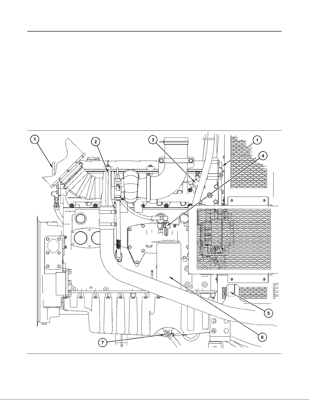
These illustrations are of both sides of the generator
set engine.
Illustration 23 g03810011
Right-Hand View of Engine (Typical Example)
(1) Lifting Eye (2) Turbocharger
Page 27
M0112246-02 27
Product Information Section
Model View Illustrations
(3) Coolant Sampling Valve
(4) Oil Sampling Valve
(5) Crankshaft Damper
(6) Oil Filter
(7) Oil Pan Drain
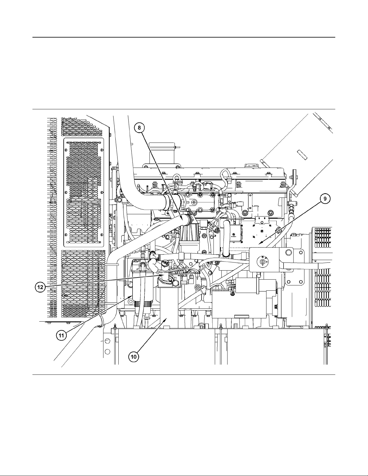
Illustration 24 g03810012
Left-Hand View of Engine (Typical Example)
(8) Crankcase Breather
(9) Electronic Control Module
(10) Secondary Fuel Filter
(11) Primary Fuel Filter (Water Separator)
(12) Fuel Priming Pump
Page 28
28 M0112246-02
Product Information Section
Product Description
i06101945
Product Description
SMCS Code: 1000; 4450; 4491
Intended Use
This Power Generator is intended to be used to
generate electrical power.
Engine Information
The Caterpillar engine has the following
characteristics:
• Four stroke cycle
• Direct fuel injection
• Hydraulically actuated electronic unit injection
• Turbocharging
• Radiator cooled
Engine Specifications
Table 1
C9 Engine Specifications
Arrangement and Cylinders In-Line 6 cylinder
Bore 112 mm (4.4 inch)
Stroke 149 mm (5.9 inch)
Aspiration Turbocharged Aftercooled
Displacement 8.8 L (537 in
3
)
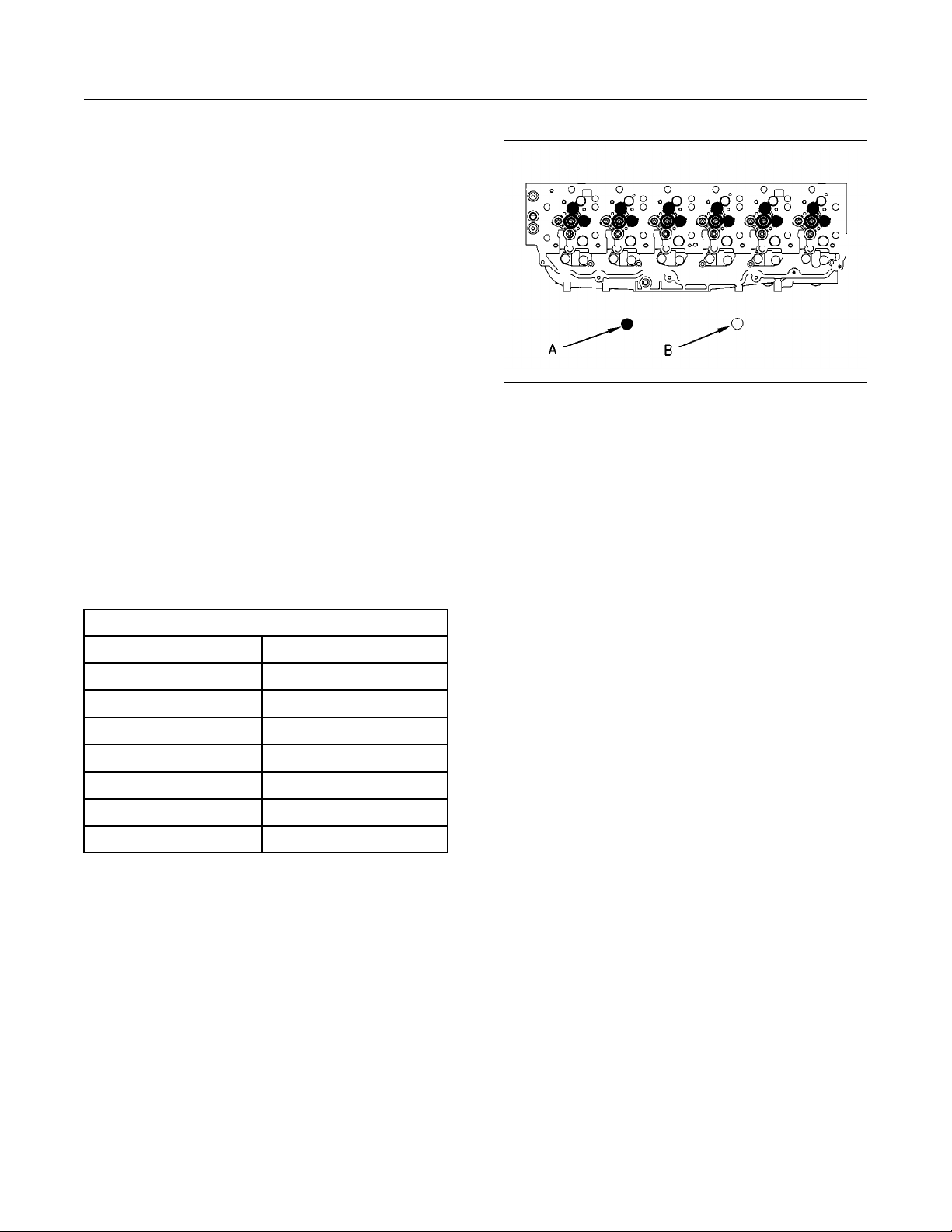
Illustration 25 g00920494
Cylinder and valve location
(A) Exhaust valve
(B) Inlet valve
Electronic Engine Features
These Caterpillar Engines are designed for electronic
controls. These engines have an integral on board
computer that is called an Electronic Control Module
(ECM). The ECM monitors current engine conditions
and power requirements. The optimum engine
response is calculated and instructions are sent to
the engine control systems. The systems respond
and the engine responds accordingly. Total engine
control is realized through the control of the fuel
system and the engine speed/timing system. The
electronic engine control system provides the
following features:
• Engine speed governing
• Injection timing control
Firing Order
Rotation (flywheel end)
Compression Ratio
1-5-3-6-2-4
Counterclockwise
16.1:1
Note: The front end of the engine is opposite the
flywheel end of the engine. The left side and the right
side of the engine are determined from the flywheel
end. The number 1 cylinder is the front cylinder.
• Automatic air/fuel ratio control
• Torque rise shaping
• Engine monitoring and protection
The ECM provides the electronic governing of fuel
delivery in order to dictate the following engine
controls: engine speed setpoint, engine timing
accuracy, air/fuel ratio control and torque rise fuel
setting.
Electronically controlled, mechanically actuated unit
injectors combine the pumping, electronic fuel
metering (duration and timing), and injecting
elements of the fuel system into a single unit. Each
cylinder has an independent unit injector.
Page 29

M0112246-02 29
Product Information Section
Product Description
Fuel metering is controlled by an electrical signal that
is sent to the injector solenoid from the ECM. High
fuel injection pressures are produced by the unit
injector pump. High injection pressures and accurate
fuel metering ensure good fuel atomization and
thorough combustion. This state-of-the-art
technology provides the engine with the following
benefits: reduced fuel consumption, controlled smoke
emissions and electronically controlled acceleration
ramp rates.
The engine timing control and speed control are
provided by the ECM. The speed/timing circuit
consists of two speed/timing sensors. During engine
cranking, the ECM uses the timing signal from the
secondary speed/timing sensor. The timing signal
from the primary speed/timing sensor is used by the
ECM while the engine speed is greater than cranking
speed. Utilizing two sensors for this circuit has
several advantages. Each of the speed/timing
sensors is treated as a discrete component by the
ECM. If the signal from one of the sensors becomes
suspect the ECM will use the signal from the other
sensor in order to keep the engine operational.
Injection duration is also managed by the ECM. The
duration of the fuel injection cycle determines the
engine speed. The placement of the injection cycle in
relation to the crankshaft position will determine the
timing advance. The speed/timing circuit provides
information to the fuel cooled ECM for detection of
crankshaft position and engine speed. This
information is utilized by the ECM in order to control
desired engine speed and engine timing.
The ECM changes injection timing according to
engine operating conditions and demand. Improved
timing control results in improved performance.
Improvements in several aspects of engine operation
will be realized: better engine starting ability, shorter
response times, reduced emissions, reduced noise
and optimized fuel consumption.
Engine monitoring and interactive diagnostics are
also provided by the ECM. Essential engine
operating conditions and diagnostic information are
monitored and recorded in the ECM memory. The
ECM quantifies the information. The information is
then compared to an acceptable range of values. If
the values are not within the acceptable range, then
the diagnostic information is communicated to the
operator and the abnormal condition is stored in ECM
memory.
For more information on electronic engine features,
refer to the Operation and Maintenance Manual,
“Engine Features and Controls” topic (Operation
Section).
Hydraulic Electronic Unit Injectors
Hydraulically Actuated Electronic Unit Injectors
(HEUI) perform the following functions: pumping of
fuel, fuel metering and injection timing.
The unit injectors are controlled by the ECM which
uses the camshaft position and the engine speed
signals from the engine speed/timing sensors and the
inlet air pressure sensors. The rated rpm of the
engine is identified on the Information Plate.
Engine Cooling and Lubrication
The cooling system consists of the following
components:
• Centrifugal pump that is driven by belts
• Water temperature regulator which regulates the
engine coolant temperature
• Oil cooler
The engine lubricating oil that is supplied is cooled by
an engine oil cooler. The engine lubricating oil is also
filtered. Bypass valves provide unrestricted flow of
lubrication oil to the engine components during the
following conditions:
• High oil viscosity
• Plugged oil cooler or plugged oil filter elements
(paper cartridge)
Engine Service Life
Engine efficiency and maximum utilization of engine
performance depend on the adherence to proper
operation and maintenance recommendations. In
addition, use recommended fuels, coolants, and
lubricants. Use the Operation and Maintenance
Manual as a guide for required engine maintenance.
Expected engine life is predicted by the average
power that is demanded. The average power that is
demanded is based on fuel consumption of the
engine over a time. Reduced hours of operation at
full throttle and/or operating at reduced throttle
settings result in a lower average power demand.
Reduced hours of operation will increase the length
of operating time before an engine overhaul is
required. For more information, refer to Operation
and Maintenance Manual, SEBU7878, “Overhaul
Considerations”.
Generator Description
These brushless generators are used with the
following loads: mixed loads of motors and lights,
SCR-controlled equipment, computer centers,
installations of communications and petroleum
drilling applications. The elimination of the brushes in
the field circuit reduces maintenance. The elimination
of the brushes in the field circuit increases reliability.
The elimination of brushes provides a higher degree
of protection in potentially hazardous atmospheres.
Page 30

30 M0112246-02
Product Information Section
Product Description
The generator set packages can be utilized for prime
power generation or standby power generation. The
generator set packages can be used in land-based
applications or marine applications.
The generators have four poles. The generators have
six or twelve lead configurations. The configuration
depends on the frame size. The generators can
produce electrical power in either 50 Hz or 60 Hz
applications.
Aftermarket Products and
Caterpillar Engines
When auxiliary devices, accessories, or consumable
(filters, additives, catalysts,) which are made by other
manufacturers are used on Cat products, the Cat
warranty is not affected simply because of such use.
However, failures that result from the installation
or use of other manufacturers devices,
accessories, or consumable are NOT Cat defects.
Therefore, the defects are NOT covered under the
Cat warranty.
Page 31
M0112246-02 31
Product Information Section
Product Identification Information
Product Identification
Information
i06102380
Plate Locations and Film
Locations
SMCS Code: 1000; 4450
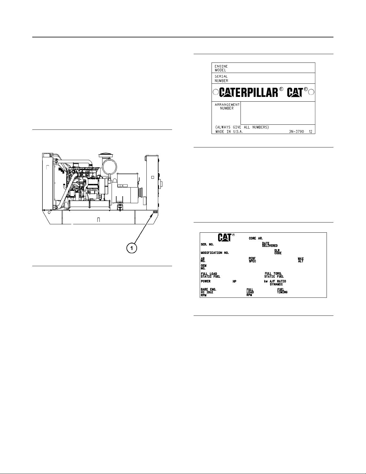
Illustration 27 g00123229
The following information is stamped on the Serial
Number Plate: engine serial number, model and
arrangement number.
Illustration 26 g03810286
(1) Location of the identification plate for the
generator set
Engine Identification
Caterpillar engines are identified with serial numbers,
with performance specification numbers, and with
arrangement numbers. In some of the cases,
modification numbers are used. These numbers are
shown on the Serial Number Plate and the
Information Plate that are mounted on the engine.
Caterpillar dealers need these numbers in order to
determine the components that were included with
the engine. This permits accurate identification of
replacement part numbers.
Engine Serial Number Plate (1)
The Serial Number Plate is on the rear left side of the
valve cover base.
Engine Information Plate (2)
The Information Plate is located toward the rear of
the top flat surface of the valve cover. The engine
information plate faces the right side of the engine.
Illustration 28 g01181026
Typical information plate
The following information is stamped on the
Information Plate: engine's maximum altitude,
horsepower, high idle, full load rpm, fuel settings and
other information.
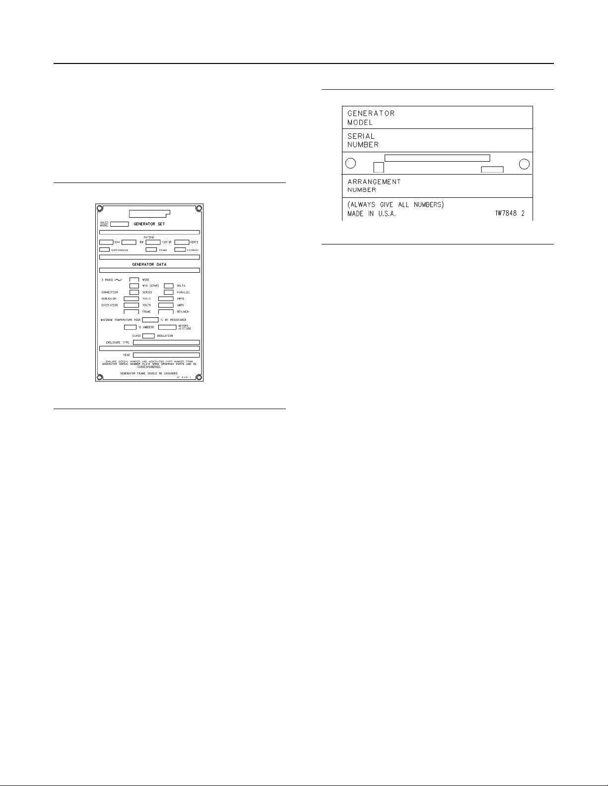
Generator Serial Number Plate and
Information Plate (3)
The generator identification and information plate is
located on the left side of the generator.
Page 32
32 M0112246-02
Product Information Section
Generator Set Intended for Stationary Use Only
When service is required, the information that is
given on this plate should be used. The generator
identification and information plate includes the
following information: serial number, model number
and the rating of the generator set. The generator set
consists of the engine and the generator. All pertinent
generator data is also included on the plate in order
to provide the information that is necessary to order
parts.
Illustration 30 g00601027
Serial Number Plate
Serial Number Plate for the Genset
(4)
Illustration 29 g00572840
Generator Identification Plate
The serial number plate for the genset is located on
the back of the terminal box.
i07424348
Generator Set Intended for
Stationary Use Only
SMCS Code: 1000; 7002
THE FOLLOWING NOTICE IS INTENDED ONLY
FOR UNITS SHIPPED INTO THE UNITED STATES
OF AMERICA, CANADA OR UNITED STATES
TERRITORIES
For units marked as being intended for stationary use
only, which are used in the United States of America,
United States Territories or Canada, the following
restrictions apply:
This generating set may only be used in stationary
applications, as defined by the Environmental
Protection Agency (EPA) Regulation in Title 40 of the
Code of Federal Regulations (40 CFR Part 89.2(2)).
The definition of stationary, per the regulations, is
that a) the unit will remain at a single site at a
building, structure, facility or installation for more than
12 consecutive months, or b) will remain at a
seasonal source during it's full annual operation
period, as defined in 40 CFR 89.2(2)(iii).
The following United States Territories must comply
with United States EPA regulations: Puerto Rico,
Virgin Islands, Guam, American Somoa and the
Commonwealth of the Northern Mariana Islands.
Page 33

M0112246-02 33
Product Information Section
Emissions Certification Film
i08085827
Emissions Certification Film
SMCS Code: 1000; 7405
Consult your Cat dealer for an Emission Control
Warranty Statement.
The emission certification film is on the engine.
i04397923
Reference Information
SMCS Code: 1000; 4450
Information for the following items may be needed to
order parts. Locate the information for your engine.
Record the information in the appropriate space.
Make a copy of this list for a record. Retain the
information for future reference.
Record for Reference
Engine Model
Engine Serial Number
kW Rating
Excitation System
AREP
Self-Excited
Permanent Magnet
Engine Arrangement Number
Modification Number
Engine Low Idle Speed
Engine Full Load Speed
Performance Specification Number
Primary Fuel Filter Element
Secondary Fuel Filter Element
Engine Oil Filter Element
Auxiliary Oil Filter Element
Supplemental Coolant Additive Maintenance
Element
Engine Oil Capacity
Total Cooling System Capacity
Air Cleaner Element
Fan Drive Belt
Alternator Belt
Generator Arrangement Number
Generator Set Serial Number
Generator Frame Size
Voltage Rating
Page 34
34 M0112246-02
Operation Section
Lifting and Storage
Operation Section
Lifting and Storage
i07942232
Product Lifting
SMCS Code: 7000; 7002
NOTICE
Improper lifting or tiedowns can allow load to shift
and can cause injury and damage.
Use a hoist to remove heavy components. Use an
adjustable lifting beam, if necessary. Some removals
require lifting fixtures to obtain proper balance and
safety.
Lifting eyes are designed and installed for the
specific arrangement. Alterations to the lifting eyes
and/or the engine make the lifting eyes and the lifting
fixtures obsolete. If alterations are made, ensure that
proper lifting devices are provided. Consult your
Caterpillar dealer for information regarding fixtures
for proper engine lifting.
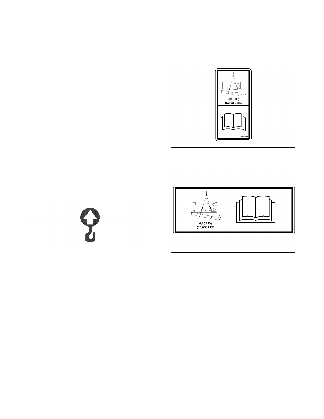
A combination of the following labels will be on the
genset. Take care to review the weight limits before
lifting the genset.
Illustration 32 g01186369
Typical example
Illustration 31 g01034418
Label for lifting eye
Lifting labels are on the lifting eyes and on the bottom
of the genset. Lifting labels may be placed in other
locations also. These labels designate the proper
lifting locations for the genset and the weight that
may be safely lifted from the location. Some gensets
may be lifted at the base of the genset. Use the
configuration that is on the lifting label to lift the
generator set. Use lifting devices that are properly
rated for the weight of the generator set.
On some enclosed generator sets, it may be
necessary to remove a top panel of the enclosure to
access the lifting eye.
Note: Lifting a generator set with a fuel tank requires
special equipment and procedures. Do not lift the unit
with fuel in the fuel tank.
A special lifting device is available for lifting the
engine out of the genset. Consult your Caterpillar
dealer for further information.
Illustration 33 g03696693
Typical example
i03978571
Product Storage
SMCS Code: 7002
Note: If storage for more than 1 yr is necessary,
contact your local Cat dealer for the preferred
storage procedure.
Engine
Storage (Less Than One Year)
If an engine is not used, oil can run off the following
parts that normally receive lubrication: cylinder walls,
piston rings, main bearings, connecting rod bearings,
crankshaft and gears.
This lack of lubricant allows corrosion to begin to
appear on the metal. This condition is worse in areas
of high humidity.
Page 35

M0112246-02 35
Operation Section
Product Storage
When the engine is started again, metal to metal
contact will cause wear before the surfaces receive
oil. To minimize this wear, use the starter to turn the
engine with the throttle in the FUEL OFF position.
When oil pressure is shown on the pressure gauge,
start the engine.
1. Clean the engine of any dirt, rust, grease, and oil.
Inspect the exterior. Paint areas that contain paint
damage with a good quality paint.
2. Remove dirt from the air cleaners. Check all seals,
gaskets, and the filter element for damage.
3. Apply lubricant to all points in this Operation and
Maintenance Manual, “Maintenance Interval
Schedule”.
4. Drain the crankcase oil. Replace the crankcase oil
and change the oil filters. For the proper
procedure, refer to this Operation and
Maintenance Manual.
5. If the engine is equipped with an air starting motor,
fill the reservoir with the following mixture: 50
percent volatile corrosion inhibitor oil
(<nomen>VCI oil</nomen>) and 50 percent
engine oil.
6. Add VCI oil to the crankcase oil. The volume of
VCI oil in the crankcase oil should be 3 to 4
percent.
Note: If the engine crankcase is full, drain enough
engine oil so the mixture can be added.
7. Remove the air filter elements. Turn the engine at
cranking speed with the throttle control in FUEL
OFF position. Use a sprayer to add a mixture of 50
percent VCI oil and 50 percent engine oil into the
air inlet or turbocharger inlet.
Note: The mixture of VCI oil can be added to the inlet
by removing the plug for checking turbocharger boost
pressure. The minimum application rate for the VCI
oil mixture is 5.5 mL per L (3 oz per 1000 cu in) of
engine displacement.
8. Use a sprayer to apply a mixture of 50 percent VCI
oil and 50 percent crankcase oil into the exhaust
openings. The minimum application rate for the oil
mixture is 5.5 mL per L (3 oz per 1000 cu in) of
engine displacement. Seal the exhaust pipe and
seal any drain holes in the muffler.
9. Remove the fuel from the secondary fuel filter
housing. Alternately, empty and reinstall the spinon fuel filter element in order to remove any dirt
and water. Drain any sleeve metering fuel pump.
Clean the primary fuel filter. Fill with calibration
fluid or kerosene. Install the primary fuel filter and
operate the priming pump. This procedure will
send clean oil to the secondary filter and the
engine.
Open the fuel tank drain valve in order to drain any
water and dirt from the fuel tank. Apply a spray of
calibration fluid or kerosene at the rate of
30 mL per 30 L (1 oz per 7.50 gal US) of fuel tank
capacity in order to prevent rust in the fuel tank.
Add 0.15 mL per L (.02 oz per 1 gal US) of
commercial biocide such as Biobor JF to the fuel.
Apply a small amount of oil to the threads on the
fuel tank filler neck and install the cap. Seal all
openings to the tank in order to prevent
evaporation of the fuel and as a preservative.
10. Remove the fuel nozzles or spark plugs. Apply
30 mL (1 oz) of the mixture of oils (50 percent VCI
oil and 50 percent engine oil) into each cylinder.
Use a bar or a turning tool in order to turn over the
engine slowly. This procedure puts the oil on the
cylinder walls. Install all fuel nozzles or spark plugs
and tighten to the correct torque.
11. Spray a thin amount of a mixture of 50 percent
VCI oil and 50 percent engine oil onto the following
components: flywheel, ring gear teeth and starter
pinion. Install the covers in order to prevent
evaporation of the vapors from the VCI oil.
12. Apply a heavy amount of Cat Multipurpose
Grease (MPGM) to all outside parts that move,
such as rod threads, ball joints, linkage.
Note: Install all covers. Ensure that tape has been
installed over all openings, air inlets, exhaust
openings, the flywheel housing, the crankcase
breathers, the dipstick tubes.
Ensure that all covers are airtight and
weatherproof. Use a waterproof weather resistant
tape such as Kendall No. 231 or an equivalent. Do
not use duct tape. Duct tape will only seal for a
short time.
13. Under most conditions, removing the batteries is
the best procedure. As an alternative, place the
batteries in storage. As needed, periodically
charge the batteries while the batteries are in
storage.
If the batteries are not removed, wash the tops of
the batteries until the tops are clean. Apply an
electrical charge to the batteries in order to obtain
a specific gravity of 1.225.
Page 36

36 M0112246-02
Operation Section
Product Storage
Disconnect the battery terminals. Place a plastic
cover over the batteries.
Note: For additional information, refer to Special
Instruction, SEHS7633, “Battery Test Procedure”.
14. Loosen all belts.
15. Place a waterproof cover over the engine. Ensure
that the engine cover is secure. The cover should
be loose enough to allow air to circulate around
the engine in order to prevent damage from
condensation.
16. Attach a tag with the storage date to the engine.
17. Remove the waterproof cover at 2 month or 3
month intervals in order to check the engine for
corrosion. If the engine has signs of corrosion,
repeat the protection procedure.
Coolant System
Completely fill the cooling system before storage.
Refer to this Operation and Maintenance Manual,
“Refill Capacities and Recommendations” for more
information about coolants.
9. Check the condition of all rubber hoses. Replace
any worn hoses. Replace any damaged hoses.
10. Before start-up, test the cooling system for a 3
percent ro a 6 percent concentration of coolant
conditioner. Add liquid coolant conditioner or a
coolant conditioner element, if equipped.
Test the coolant mixture for proper nitrite level. If
necessary, adjust the coolant mixture.
Prime the engine with clean diesel fuel before
starting.
11. Ensure that the cooling system is clean. Ensure
that the system is full. Ensure that the system has
the correct amount of supplemental cooling
system conditioner.
12. On the first day of operation, check the entire
engine several times for leaks and correct
operation.
13. If the engine was removed from storage in which
temperatures of less than -12°C (10°F) were
encountered, refer to Service Manual, SEBU5898,
“Cold Weather Recommendations Operation and
Maintenance”.
Removal from Storage
1. Remove all outside protective covers.
2. Change the oil and filters.
3. Check the condition of the fan and alternator belts.
Replace the belts, if necessary. Refer to this
Operation and Maintenance Manual, “Belts Inspect/Adjust/Replace” for the correct procedure.
4. Replace the fuel filter elements.
5. Remove the plastic covers from the air cleaner
elements.
6. Use a bar or a turning tool in order to turn the
engine in the normal direction of rotation. The
procedure ensures that no hydraulic locks or
resistance exist.
7. Before starting the engine, remove the valve cover
or covers. Put a large amount of engine oil on the
camshaft, cam followers, and valve mechanism in
order to prevent damage to the mechanism.
8. Pressure lubricate the engine before starting the
engine. Pressure lubricating the engine ensures
immediate lubrication and prevents damage to the
engine during the first few minutes of engine
operation. If the engine is not equipped with a
prelube pump, contact your Cat dealer for
information about lubrication of the engine before
starting the engine.
Generator
Storage (Less Than One Year)
When a generator is in storage, moisture condenses
in the windings. To minimize condensation, always
place the generator in a dry storage area. Seal all
openings with tape.
If a brush-type generator (SRCR) is being stored, lift
the brushes off the slip ring to prevent chemical
damage to the slip ring. Attach a tag to the generator
which states that the brushes have been lifted.
Perform a resistance check of the windings. Record
this reading. This check is done in order to provide a
base line for determining whether moisture or
winding deterioration occurs during storage.
Removal From Storage
Remove all protective covers. Reseat the brushes on
the slip ring for SRCR generators.
Before start-up of a generator, use a megohmmeter
to check insulation resistance for moisture and/or
foreign material. Refer to this Operation and
Maintenance Manual, “Generator Start-up Check
List” for the procedure. A resistance reading of 1
megohm or less indicates that the winding has
absorbed too much moisture.
Page 37

M0112246-02 37
Operation Section
Product Storage
Use one of the following methods for drying the
generator in order to remove moisture which is
caused by high humidity or dampness:
1. Place the generator in an oven which is no hotter
than 85°C (185°F) for 4 hours.
2. Use a canvas enclosure around the generator and
heating lamps to increase the ambient
temperature. Provide an opening in the top of the
canvas in order to release the moisture.
3. Send a low voltage current through the windings in
order to increase the temperature of the windings
to 85°C (185°F).
Megohmmeter Checks
Test the main stator windings with a megohmmeter in
the following situations:
1. Before the initial start-up of the generator set
2. Every 3 months if the generator operates in a
humid environment
3. If the generator has not been run under load for3
months or more
These intervals are only recommendations. Perform
a megohmmeter test more frequently if the following
conditions exist: extreme humidity, salty environment
and the last megohmmeter test was close to 1
megohm.
Additional Information
For additional information about storage procedures,
refer to Special Instruction, SEHS9031, “Storage
Procedure for Cat Products”.
Page 38

38 M0112246-02
Operation Section
Installation
Installation
i07911792
Product Installation
SMCS Code: 1000; 1404; 4450; 7002
Assembly Instructions for Partially
Completed Machinery per the EU
Machinery Safety Directive 2006/
42/EC
To ensure that this product is correctly installed and
does not compromise safety and health, refer to the
material in the appropriate Application and
Installation Guide and the material contained in this
Operations and Maintenance Manual.
Receiving Inspection
If the generator is received during cold weather, allow
the unit to reach room temperature before you
remove the protective packing material. Warming the
generator to room temperature will prevent the
following problems:
• Water condensation on cold surfaces
• Early failures due to wet windings
• Early failures due to wet insulating materials
Unpacking and Storage
Moving the Generator
The hoist and the hoist cables should have a rating
that is greater than the weight of the generator. When
the unit is moved, ensure that the generator is
supported by the lift truck fork tines. Also ensure that
the generator is balanced on the lift truck fork tines.
Slide the fork tines beneath the attached skid to lift
the generator.
Storage
Short Time Storage
If the generator is not installed immediately, store the
generator in a clean area. This area should also have
the following conditions: low humidity, stable
humidity, and stable temperature. Space heaters
must be energized to keep condensation from the
windings. All accessory equipment that is supplied
with the unit should be stored with the generator. The
combined unit should be covered with a durable
cover to protect against the following contaminants:
• Dust
• Dirt
• Moisture
• Other airborne abrasive material
Long Time Storage
A storage period more than 6 months should be
preceded by the following preparation:
1. Install desiccant bags inside the exciter's cover
and install desiccant bags inside the screen of the
fan.
2. Seal the unit in a covering of plastic or other
material that has been designed for that purpose.
Improper lift rigging can allow unit to tumble
causing injury and damage.
Do not use the engine lifting eyes to remove the engine and generator together.
Unpack the equipment with care to avoid scratching
the painted surfaces. Move the unit to the mounting
location. The unit can be moved by either of the
following methods:
• Attach an overhead crane to the eyebolts that are
installed on the generator frame.
• Use a lift truck to lift the generator.
NOTICE
Page 39
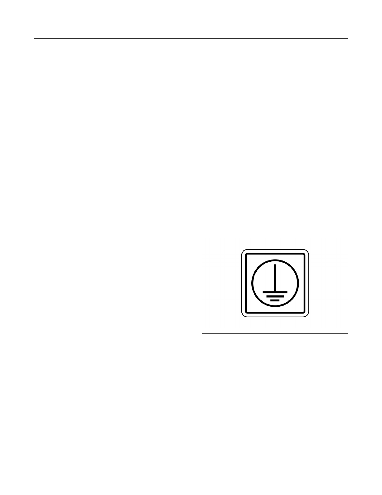
M0112246-02 39
Operation Section
Product Installation
3. Adequately tag the generator. Tagging will ensure
that preservative greases and desiccant bags are
removed before the unit is placed in operation.
Bearing Inspection
Ball bearing generators use grease. This grease is
subject to deterioration. If the generator is stored
longer than 1 year, new ball bearings should be
installed. These bearings should be greased to the
proper level prior to being put into operation. If
inspection indicates that bearings are free of rust or
corrosion, and no noise or excessive vibration appear
on start-up, replacement is not necessary.
Location
The location of the generator must comply with all
local regulations. The location of the generator must
also comply with all special industrial regulations.
Locate the generator in an area that meets the
following requirements:
• Clean
• Dry
• Well ventilated
Load Connections – Generator Set
Output
For units equipped with T– frame breaker: Installer
shall connect conductors in accordance with
separate T-frame breaker terminal instruction
provided with unit. All conductors shall be sized
based upon the 75° C (167° F) ampacities within
Table 310-16 of the National Electrical Code, ANSI/
NFPA 70, of no less than 100 percent of the
maximum current that the circuit carries during rated
conditions. All conductors shall be rated 90° C
(194° F) or greater. For units equipped with either Rframe breaker or bus bar (terminal strip) connections:
Installer shall use UL Listed terminal connectors and
install in accordance with terminal connector
manufacturer instructions. Terminal connectors shall
be used within UL rating limit and suitable for the
application. A field wiring terminal shall be sized for
the connection of a conductor having an ampacity
based on the 75° C (167° F) column of Table 310-16
of the National Electrical Code, ANSI/NFPA 70, of no
less than 100 percent of the maximum current that
the circuit carries during rated conditions. All
conductors shall be rated 90° C (194° F) or greater.
Equipment Ground Connection
• Easily accessible for inspection and maintenance
Do not obstruct air inlet openings. Do not obstruct
discharge openings. Air flow must reach these
openings. If the generator is exposed to harsh
environmental conditions, the generator can be
modified in the field to add filters and space heaters.
In addition, a more rigid periodic maintenance
schedule should be established.
UL 2200
IMPORTANT SAFETY INSTRUCTIONS - SAVE
THESE INSTRUCTIONS
This manual contains important instructions that
shall be followed during installation and
maintenance of the generator and batteries.
Factory UL Listed option requires generator set be
installed to the minimum UL requirements contained
in this section. Installation and sizing shall be
performed by qualified personnel. Other installation
site requirements may apply in addition to those
contained in this section.
Illustration 34 g03368914
Unit ground bar shall be connected in accordance
with National Electrical Code, ANSI/NFPA 70, Article
250. Installer shall use UL Listed terminal connectors
and install in accordance with terminal connector
manufacturer instructions. Terminal connectors shall
be used within UL rating limit and suitable for the
application. A field wiring ground terminal shall be
sized for the connection based on the minimum
ground conductor size required by UL as shown in
the corresponding column of Table 2 .
Over-current protection devices
For units without installed circuit breaker over-current
protection option, installer shall use off package-
mounted UL Listed circuit breaker within 7.6 m (25 ft)
of generator set.
Page 40
40 M0112246-02
Operation Section
Product Installation
Table 2
Minimum Ground Conductor Size
AWG or kcmil (mm2)
(Amps) Copper Aluminum or copper-clad aluminum
400 1/0 (53.5) 3/0 (85.0)
500 2/0 (67.4) 4/0 (107.2)
600 2/0 (67.4) 4/0 (107.2)
800 3/0 (85.0) 250 (127)
1000 3/0 (85.0) 250 (127)
1200 3/0 (85.0) 250 (127)
1600 3/0 (85.0) 250 (127)
2000 3/0 (85.0) 250 (127)
2500 3/0 (85.0) 250 (127)
Batteries
Servicing of batteries is to be performed or
supervised by personnel knowledgeable of batteries
and the required precautions. Keep unauthorized
personnel away from batteries.
When replacing batteries, use the same number and
the following type batteries:
Cat Premium High Output (PHO) Batteries
Standard battery (wet) BCI Group 31, Calcium Lead
Alloy Grid Design, 1000 CCA,
Oversize battery (wet) BCI Group 4D, Calcium Lead
Alloy Grid Design, 1400 CCA,
Standard battery (dry) BCI Group 31, Calcium Lead
Alloy Grid Design, 950 CCA,
Oversize battery (dry) BCI Group 4D, Low
Maintenance, Hybrid Construction, 1300 CCA,
Do not dispose of battery or batteries in a fire.
The battery is capable of exploding.
1. Remove watches, rings, or other metal objects, 2)
Use tools with insulated handles
The electrolyte is a dilute sulfuric acid that is
harmful to the skin and eyes. It is electrically
conductive and corrosive.
It is electrically conductive and corrosive. The
following procedures are to be observed:
1. Wear full eye protection and protective clothing,
2. Where electrolyte contacts the skin, wash it off
immediately with water,
3. Where electrolyte contacts the eyes, flush
thoroughly and immediately with water and seek
medical attention, and
4. Spilled electrolyte is to be washed down with an
acid neutralizing agent. A common practice is to
use a solution of 1 lb (500 grams) bicarbonate of
soda to 1 gallon (4 L) of water. The bicarbonate of
soda solution is to be added until the evidence of
reaction (foaming) has ceased. The resulting liquid
is to be flushed with water and the area dried.
Do not open or mutilate the battery or batteries.
Released electrolyte has been know to be
harmful to the skin and eyes and to be toxic.
A battery presents a risk of electrical shock and
high short circuit current.
Lead-acid batteries present a risk of fire because
they generate hydrogen gas.
The following procedures are to be followed:
1. DO NOT SMOKE when near batteries,
2. DO NOT cause flame or spark in battery area, and
Page 41

M0112246-02 41
Operation Section
Product Installation
1. Discharge static electricity from body before
touching batteries by first touching a grounded
metal surface.
UL location requirements
Open generator sets shall be installed and located in
a manner that contact with people is minimized.
Page 42
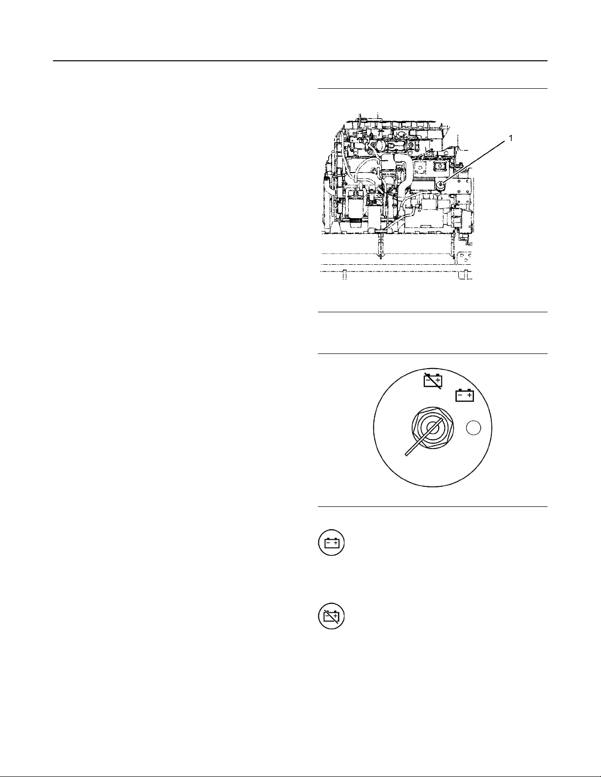
42 M0112246-02
Operation Section
Features and Controls
Features and Controls
i04537584
Alarms and Shutoffs
SMCS Code: 7400
Alarms and shutoffs are electronically controlled. The
operation of all alarms and shutoffs utilize
components which are actuated by a sensing unit.
The alarms and shutoffs are set at critical operating
temperatures, pressures, or speeds in order to
protect the engine from damage.
The alarms function in order to warn the operator
when an abnormal operating condition occurs. The
shutoffs function in order to shut down the engine
when a more critical abnormal operating condition
occurs. The shutoffs help to prevent damage to the
equipment.
If an engine protective device shuts off the engine,
always determine the cause of the shutoff. Make the
necessary repairs before attempting to start the
engine.
Become familiar with the following information:
• Types of the alarm and shutoff controls
• Locations of the alarm and shutoff controls
• Conditions which cause each control to function
• Resetting procedure that is required before
starting the engine
i03671082
Battery Disconnect Switch
(If Equipped)
SMCS Code: 1411
The battery disconnect switch is on the left side of the
engine near the rear of the engine.
Illustration 35 g01970753
(1) Battery disconnect switch
Illustration 36 g01970893
ON – To activate the electrical system,
insert the disconnect switch key and
turn the battery disconnect switch
clockwise. The battery disconnect switch must
be turned to the ON position before you start the
engine.
OFF – To deactivate the electrical
system, turn the battery disconnect
switch counterclockwise to the OFF
position.
The battery disconnect switch operates differently
than the engine start switch. When the battery
disconnect switch is in the OFF position, the
electrical system is disabled. When the engine start
switch is turned to the OFF position and the battery
disconnect switch is turned to the ON position, the
battery remains connected to the entire electrical
system.
Page 43

M0112246-02 43
Operation Section
Cold Start Strategy
Turn the battery disconnect switch to the OFF
position and remove the disconnect switch key when
you service the electrical system or other
components on the engine.
Turn the battery disconnect switch to the OFF
position and remove the disconnect switch key if you
do not operate the engine for an extended period of a
month or more. This will prevent drainage of the
battery.
NOTICE
Never move the battery disconnect switch to the OFF
position while the engine is operating. Serious damage to the electrical system could result.
To ensure that no damage to the engine occurs,
verify that the engine is fully operational before
cranking the engine. Do not crank an engine that is
not fully operational.
Perform the following procedure in order to check the
battery disconnect switch for proper operation:
1. With the battery disconnect switch in the ON
position, verify that electrical components in the
operator compartment are functioning. Verify that
the hour meter is displaying information. Verify that
the engine will crank.
• The coolant temperature reaches 49 °C (120 °F).
• The engine has run for 20 minutes.
2. Turn the battery disconnect switch to the OFF
position.
3. Verify that the following items are not functioning:
electrical components in the operator
compartment, hour meter and engine cranking. If
any of the items continue to function with the
battery disconnect switch in the OFF position,
consult your Caterpillar dealer.
i01324368
Cold Start Strategy
SMCS Code: 1450; 1456; 1900
The cold start strategy utilizes the input from the
coolant temperature sensor to improve starting in low
temperatures. The cold start strategy helps to provide
the following features:
• Quicker cold starts
• White smoke cleanup
• Decreased deep cycling of the battery
• Extended engine life
When the coolant temperature is below 18 °C
(64 °F), the cold start strategy is activated. The cold
start strategy deactivates under any of the following
conditions:
Page 44
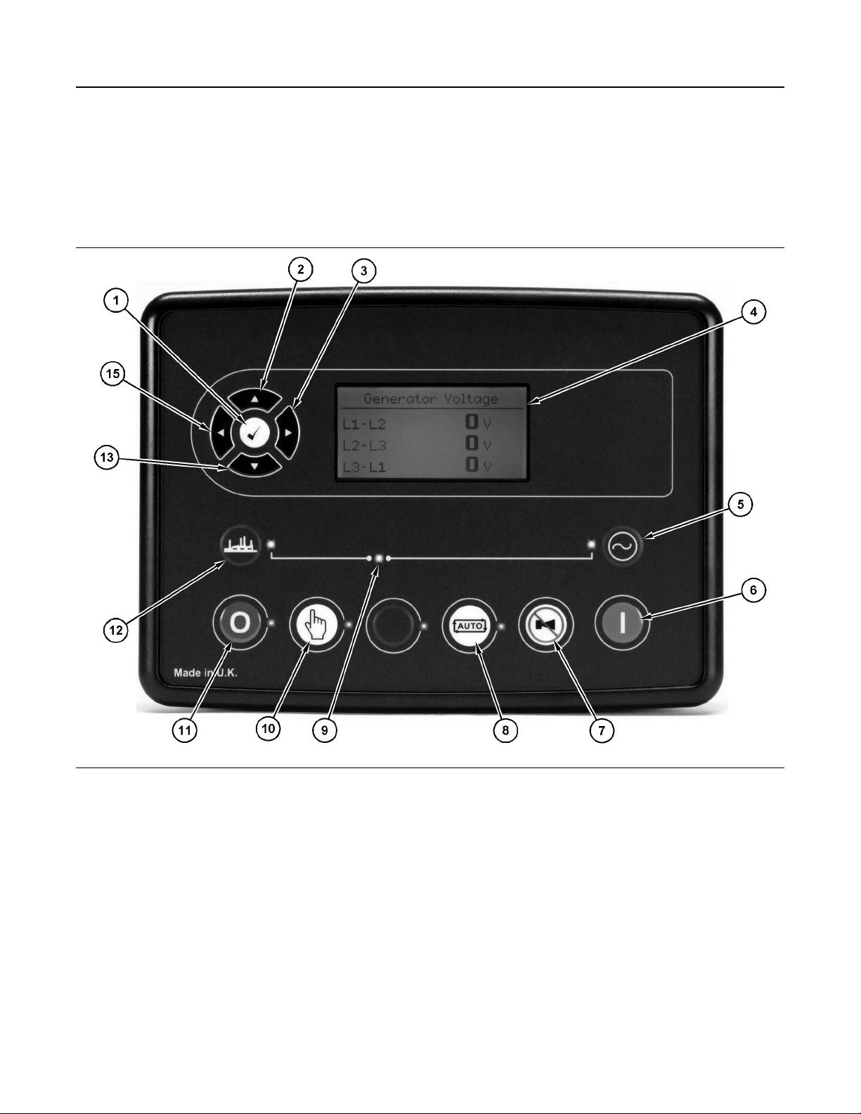
44 M0112246-02
Operation Section
Control Panel
i08288996
Control Panel
SMCS Code: 7451
GCCP1.2 (If Equipped)
Illustration 37 g06471487
(1) OK key
(2) Up key
(3) Right key
(4) Main status and instrument display
(5) Transfer to gererator
(6) Start
(7) Mute/lamp test
(8) Auto/test key
(9) Generator breaker LED
(10) Manual key
(11) Stop/Reset
(12) Open generator key
(13) Down key
(14) Left key
Function Keys
(2) Up Key – The “Up” key is used to navigate up
This section provides an overview of key functions for
this control. For detailed information about this
control module, refer to the OEM manual.
(1) OK Key – The “OK” key is used during menu
navigation to move forward (downward) through the
menu/submenu structure. The key is also used
during set point programming to save set points
changes. Pressing the OK key during set point
programming causes set point changes to be saved
to memory.
through the various menus or monitoring screens.
The key is also used during set point entry. During
numeric data entry, the key is used to increment the
digits (0-9). If the set point requires selection from a
list, then the key is used to navigate up through the
list.
(3) Right Key – The “Right” key is used during set
point adjustment. During numeric data entry, the key
is used to choose which digit is being edited. The key
is also used during certain set point adjustments to
Page 45

M0112246-02 45
Operation Section
Control Panel
select a check box or to deselect a check box. If a
box has a check mark inside, then pressing the key
will cause the check mark to disappear. If the box
does not have a check mark inside, then pressing the
key will cause a check mark to appear inside.
(4) Main Status and Instrumentation Display –
Information from the GCCP1.2 is displayed on the
main status and instrumentation display. Keys (1) (5) are used to navigate through different menu
screens. For further details, see Special Instruction,
M0085763, “TCP 2000 & TCP 3000 Control
Panel”Description of the Controls.
(5) Transfer to Generator – Operative in manual
mode only. Normal breaker key control allows the
operator to transfer the load to the generator.
Alternative breaker key control. If mains is on load,
pressing the “Transfer to Generator” key transfers the
load to the generator. If generator is on load,
pressing the “Transfer to Generator” key opens the
generator breaker. If generator and mains are off
load, pressing the “Transfer to Generator” key closes
the generator breaker.
(6) Start – The “Start” key is only active in Stop/
Reset mode. Pressing the “Start” key in manual or
test mode will cause the engine and run off load
(manual) or on load (test). Pressing the “Start” key
while in Stop/Reset mode will turn on the CAN engine
ECU (when correctly configured, and fitted to a
compatible engine ECU).
(7) Mute/Lamp Test – Pressing the “Mute/Lamp” test
key will silence the audible alarm if it is sounding, deactivate the Audible Alarm output, and illuminate all
the indicator lamps as a test feature.
(8) AUTO – Pressing the “AUTO” key causes the
module to enter the auto mode. Auto mode allows the
module to control the function of the generator
automatically. The module will monitor numerous
start requests, and once a start request is made, the
set will be automatically started, and placed on load.
Once the generator is available, the mains is taken
off load (Close Generator Output becomes inactive if
used). Upon removal of the starting signal, the
module will automatically transfer the load from the
generator (Close Generator Output becomes inactive
if used), and shut down the set observing the stop
delay timer and cooling timer as necessary. The
module will then await the next start event.
automatically instruct the changeover device to place
the generator on load (Close Generator becomes
active (if used)). Upon removal of the remote start
signal, the generator remains on load until either
selection of the stop/reset or auto modes. For further
details, see Special Instruction, M0085763, “TCP
2000 & TCP 3000 Control Panel”Manual Operation.
(11) Stop/Reset – Pressing the “Stop/Reset” key
causes the module to enter the Stop/Reset mode.
This will clear any alarm conditions for which the
triggering criteria have been removed. If the engine is
running, and the module is in Stop mode, the module
will automatically instruct the changeover device to
unload the generator (Close Generator becomes
inactive if used). The fuel supply de-energizes, and
the engine comes to a standstill. Should a Remote
Start Signal be present while operating in Stop/Reset
mode, a remote start will not occur.
(12) Transfer to Generator – Operative in manual
mode only. Normal breaker key control allows the
operator to transfer the load to the generator.
Alternative breaker key control. If mains is on load,
pressing the “Transfer to Generator” key transfers the
load to the generator. If generator is on load,
pressing the “Transfer to Generator” key opens the
generator breaker. If generator and mains are off
load, pressing the “Transfer to Generator” key closes
the generator breaker.
(13) Down Key – The “Down” key is used to navigate
down through the various menus or monitoring
screens. The key is also used during set point entry.
During numeric data entry, the key is used to
decrement the digits (0-9). If the set point requires
selection from a list, then the key is used to navigate
down through the list.
(14) Left Key – The “Left” key is used during set
point adjustment. During numeric data entry, the key
is used to choose which digit is being edited. The key
is also used during certain set point adjustments to
select a check box or to deselect a check box. If a
box has a check mark inside, then pressing the key
will cause the check mark to disappear. If the box
does not have a check mark inside, then pressing the
key will cause a check mark to appear inside.
(9) Generator Breaker LED – Operative in Manual
mode only. Normal breaker key control allows the
operator to transfer the load to the mains. Alternative
breaker key control, if generator is on load, transfers
the load to the mains. If mains is on load, opens the
mains breaker. If generator and mains are off load,
closes the mains breaker.
(10) Manual – Pressing the “Manual” key allows
manual control of the generator functions. Once in
manual mode, the module will respond to the “Start”
key, start the engine, and run off load. If the engine is
running off-load in manual mode and a remote start
signal becomes present, the module will
Page 46
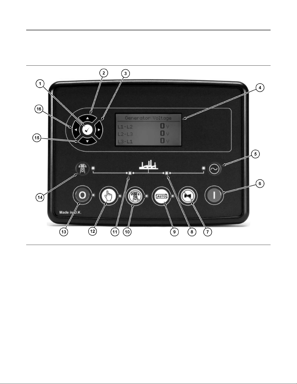
46 M0112246-02
Operation Section
Control Panel
GCCP1.3 (If Equipped)
Illustration 38 g06471489
(1) OK key
(2) Up key
(3) Right key
(4) Main status and instrument display
(5) Transfer to generator
(6) Start
Function Keys
(7) Mute/lamp test
(8) Generator breaker LED
(9) Auto key
(10) Test mode key
(11) Mains breaker LED
(12) Manual key
(13) Stop/Reset
(14) Transfer to mains key
(15) Down key
(16) Left key
The key is also used during set point entry. During
numeric data entry, the key is used to increment the
This section provides an overview of key functions for
this control. For detailed information about this
control module, refer to the OEM manual.
(1) OK Key – The “OK” key is used during menu
navigation to move forward (downward) through the
menu/submenu structure. The key is also used
during set point programming to save set points
changes. Pressing the OK key during set point
programming causes set point changes to be saved
to memory.
digits (0-9). If the set point requires selection from a
list, then the key is used to navigate up through the
list.
(3) Right Key – The “Right” key is used during set
point adjustment. During numeric data entry, the key
is used to choose which digit is being edited. The key
is also used during certain set point adjustments to
select a check box or to deselect a check box. If a
box has a check mark inside, then pressing the key
will cause the check mark to disappear. If the box
does not have a check mark inside, then pressing the
(2) Up Key – The “Up” key is used to navigate up
key will cause a check mark to appear inside.
through the various menus or monitoring screens.
Page 47

M0112246-02 47
Operation Section
Control Panel
(4) Main Status and Instrumentation Display –
Information from the TCP 3000 is displayed on the
main status and instrumentation display. Keys (1) (5) are used to navigate through different menu
screens. For further details, see Special Instruction,
M0085763, “TCP 2000 & TCP 3000 Control
Panel”Description of the Controls.
(5) Transfer to Generator – Operative in manual
mode only. Normal breaker key control allows the
operator to transfer the load to the generator.
Alternative breaker key control. If mains is on load,
pressing the “Transfer to Generator” key transfers the
load to the generator. If generator is on load,
pressing the “Transfer to Generator” key opens the
generator breaker. If generator and mains are off
load, pressing the “Transfer to Generator” key closes
the generator breaker.
(6) Start – The “Start” key is only active in Stop/
Reset mode. Pressing the “Start” key in manual or
test mode will cause the engine and run off load
(manual) or on load (test). Pressing the “Start” key
while in Stop/Reset mode will turn on the CAN engine
ECU (when correctly configured, and fitted to a
compatible engine ECU).
(7) Mute/Lamp Test – Pressing the “Mute/Lamp” test
key will silence the audible alarm if it is sounding, deactivate the Audible Alarm output, and illuminate all
the indicator lamps as a test feature.
(8) Generator Breaker LED – The generator breaker
LED is ON when the generator is on load.
(9) AUTO – Pressing the “AUTO” key causes the
module to enter the auto mode. Auto mode allows the
module to control the function of the generator
automatically. The module will monitor numerous
start requests, and once a start request is made, the
set will be automatically started, and placed on load.
Once the generator is available, the mains is taken
off load (Close Mains Output becomes inactive if
used). Upon removal of the starting signal, the
module will automatically transfer the load from the
generator (Close Mains Output becomes active if
used), and shut down the set observing the stop
delay timer and cooling timer as necessary. The
module will then await the next start event.
signal becomes present, the module will
automatically instruct the changeover device to place
the generator on load (Close Generator becomes
active (if used)). Upon removal of the remote start
signal, the generator remains on load until either
selection of the stop/reset or auto modes. For further
details, see Special Instruction, M0085763, “TCP
2000 & TCP 3000 Control Panel”Manual Operation.
(13) Stop/Reset – Pressing the “Stop/Reset” key
causes the module to enter the Stop/Reset mode.
This will clear any alarm conditions for which the
triggering criteria have been removed. If the engine is
running, and the module is in Stop mode, the module
will automatically instruct the changeover device to
unload the generator (Close Generator becomes
inactive if used), and places the mains on load (Close
Mains Output becomes active). The fuel supply deenergizes, and the engine comes to a standstill.
Should a Remote Start Signal be present while
operating in Stop/Reset mode, a remote start will not
occur.
(14) Transfer to Mains – Operative in Manual mode
only. Normal breaker key control allows the operator
to transfer the load to the mains. Alternative breaker
key control, if generator is on load, transfers the load
to the mains. If mains is on load, opens the mains
breaker. If generator and mains are off load, closes
the mains breaker.
(15) Down Key – The “Down” key is used to navigate
down through the various menus or monitoring
screens. The key is also used during set point entry.
During numeric data entry, the key is used to
decrement the digits (0-9). If the set point requires
selection from a list, then the key is used to navigate
down through the list.
(16) Left Key – The “Left” key is used during set
point adjustment. During numeric data entry, the key
is used to choose which digit is being edited. The key
is also used during certain set point adjustments to
select a check box or to deselect a check box. If a
box has a check mark inside, then pressing the key
will cause the check mark to disappear. If the box
does not have a check mark inside, then pressing the
key will cause a check mark to appear inside.
(10) Test Mode – Pressing the “Test Mode” key
causes the module to enter the test mode. In test
mode, an on load test of the generator can be
performed. Once in test mode, the module will
respond to the start button, start the engine, and run
on load. For further details, see Special Instruction,
M0085763, “TCP 2000 & TCP 3000 Control
Panel”Test Operation.
(11) Mains Breaker LED – The mains breaker LED
is ON when the mains is on load.
(12) Manual – Pressing the “Manual” key allows
manual control of the generator functions. Once in
manual mode, the module will respond to the “Start”
key, start the engine, and run off load. If the engine is
running off-load in manual mode and a remote start
Page 48
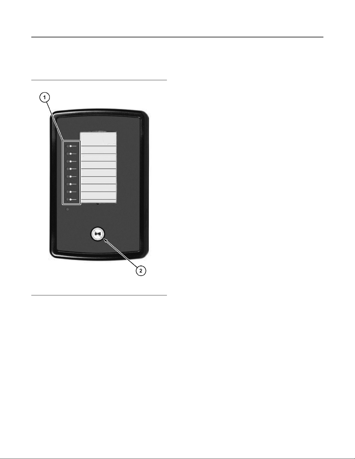
48 M0112246-02
Operation Section
Overspeed
ID Switch
DSE2548 Expansion Module
The rotary ID switch is used to select the address of
the DSE2548 expansion module, as the host control
module can give instructions to several DSE2548
expansion modules at the same time.
i07911799
Overspeed
SMCS Code: 1900; 1907; 1912; 7427
Serious damage to the engine and to the driven
components may result during engine overspeed.
Engine overspeed protection is a safety feature that
will take the necessary measures to initiate an engine
shutdown in the event of an engine overspeed
condition.
Illustration 39 g06472485
(1) Eight configurable LEDs
(2) Mute/lamp test
The DSE2548 output expansion module has the
following features/characteristics:
• Eight configurable LEDs
• Works up to 1 km (0.6 miles) from the host
controller
• 10 modules can be linked together to one host
controller
Page 49
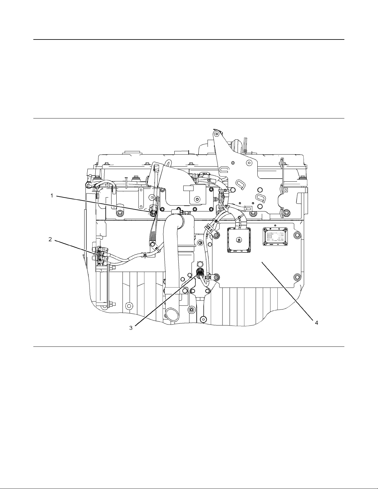
M0112246-02 49
Operation Section
Sensors and Electrical Components
i07942253
Sensors and Electrical
Components
SMCS Code: 1900; 7400
Sensor Locations
Illustration 40 g01158393
Typical example
(1) Injection actuation pressure sensor
(2) Speed/timing sensors
(3) Engine oil pressure sensor
(4) Electronic control module (ECM)
Page 50
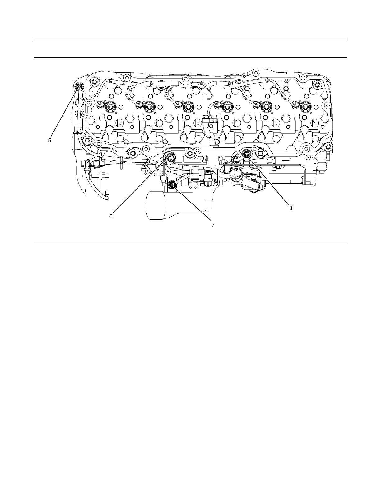
50 M0112246-02
Operation Section
Sensors and Electrical Components
Illustration 41 g01158394
Typical example
(5) Coolant temperature sensor
(6) Turbocharger outlet pressure sensor
Failure of Sensors
(7) Inlet air temperature sensor
(8) Atmospheric pressure sensor
• Measured reading of the sensor is out of
specification.
All Sensors
Inlet Air Temperature Sensor
A failure of any of the sensors may be caused by one
of the following malfunctions:
• Sensor output is open.
• Sensor output is shorted to “- battery” or “+
battery” .
Inlet air temperature sensor (7) measures the
temperature of the inlet air. The Electronic Control
Module (ECM) monitors the signal of the inlet air
temperature sensor. The output of the ECM can
indicate high inlet air temperature through a relay or a
lamp. The inlet air temperature sensor will not cause
a shutdown of the engine or any horsepower change.
Engine Speed/Timing Sensors
If the ECM does not receive a signal from the primary
speed/timing sensor, the “DIAGNOSTIC” lamp will
indicate a diagnostic fault code which will be logged
in the ECM memory.
If the ECM does not receive a signal from the primary
speed/timing sensor, the ECM will read the signal
from the secondary speed/timing sensor. The ECM
continually checks to determine if there is a signal
from both sensors (2). If either sensor fails, the faulty
sensor should be replaced.
Page 51

M0112246-02 51
Operation Section
Sensors and Electrical Components
Intermittent failure of the sensors will cause erratic
engine control.
Coolant Temperature Sensor
Coolant temperature sensor (5) monitors engine
coolant temperature. This feature is used for the
engine system diagnostics with an output from the
ECM. The output of the ECM can indicate a high
coolant temperature through a relay or a lamp.
Failure of the Coolant Temperature
Sensor
The ECM will detect a failure of the coolant
temperature sensor. The diagnostic lamp will warn
the operator about the status of the coolant
temperature sensor. Strategies that are related to the
coolant temperature sensor will be disabled if a
failure occurs. A failure of the coolant temperature
sensor will not cause a shutdown of the engine or
any horsepower change.
Page 52

52 M0112246-02
Operation Section
Engine Diagnostics
Engine Diagnostics
i03840813
Fault Logging
SMCS Code: 1000; 1900; 1901; 1902
The system provides the capability of Fault Logging.
When the Electronic Control Module (ECM)
generates an active diagnostic code, the code will be
logged in the memory of the ECM. The codes that
have been logged in the memory of the ECM can be
retrieved with Caterpillar electronic service tools. The
codes that have been logged can be cleared with
Caterpillar electronic service tools. The codes that
have been logged in the memory of the ECM will be
automatically cleared from the memory after 100
hours. The following faults cannot be cleared from
the memory of the ECM without using a factory
password: overspeed, low engine oil pressure and
high engine coolant temperature.
i01147116
Engine Operation with Active
Diagnostic Codes
SMCS Code: 1000; 1900; 1901; 1902
Each circuit component in the engine electronics
system is monitored by the Electronic Control Module
(ECM) for abnormal operation. The ECM is capable
of recognizing several abnormal conditions and
selecting an appropriate reaction.
ACTIVE diagnostic codes can indicate problems that
are as minor as a loose connection. ACTIVE
diagnostic codes can also indicate larger problems
that may be associated with the deterioration of a
component. Any condition that causes an ACTIVE
diagnostic code should be investigated immediately.
If an ACTIVE diagnostic code is present during
normal engine operation, the engine should be
serviced immediately by a qualified technician.
i01154195
Engine Operation with
Intermittent Diagnostic Codes
SMCS Code: 1000; 1900; 1901; 1902
The Electronic Control Module (ECM) is capable of
detecting abnormal operation of the electronic
components that are found on the engine. The ECM
generates an ACTIVE diagnostic code when an
abnormal condition is detected. The condition is also
logged in ECM memory. The logged information that
is stored in ECM memory is called a LOGGED
diagnostic code. This information may be useful to
the technician for troubleshooting the problem. A
diagnostic code is considered to be intermittent when
the condition is logged in ECM memory and the
condition is not currently active.
In most cases, it is not necessary to stop the engine
because of an intermittent code. However, the
operator should retrieve the codes and the operator
should reference the appropriate information in order
to identify the nature of the event. Take note of the
following characteristics of engine performance:
When an abnormal condition is recognized by the
ECM, an ACTIVE Diagnostic Code is generated. The
ECM will first communicate the condition to the
operator. This communication may include lighting a
diagnostic lamp or displaying the diagnostic condition
on a display panel.
The reaction of the ECM to an ACTIVE diagnostic
code will seldom affect more than engine
performance. Much of the data that is received from
the circuit components by the ECM is used in order to
control engine function. If a component that provides
this type of data has an ACTIVE diagnostic condition,
the data cannot be used. If a diagnostic code
becomes ACTIVE, the ECM will flag suspect data as
“INVALID DATA” . A default value that has been
predetermined will be used for the engine control that
is associated with that component. The operation of
the subsystem will continue, and the engine will
continue to run. However, loss of an electronic
component that causes an ACTIVE diagnostic code
may cause an engine shutdown.
• Low power
• Engine rpm limits
• Excessive smoke, etc
This information can be useful to help troubleshoot
the situation. If the nature of the problem persists, a
qualified service technician should be consulted. For
more information on diagnostic codes, refer to the
Troubleshooting Guide for this engine.
Page 53

M0112246-02 53
Operation Section
Configuration Parameters
i04041713
Configuration Parameters
SMCS Code: 1000; 1900; 1901; 1902
System configuration parameters are parameters
that are configured to specify the engine emissions
levels, the power rating, and the specific application.
Default values for the parameters are programmed at
the factory. Some parameters may be changed in
order to equip the engine for a specific application.
The system configuration parameters must be
reprogrammed if the Electronic Control Module
(ECM) is replaced. It is not necessary to reprogram
the system configuration parameters if you update
the ECM flash file. Certain configuration parameters
are stamped into the engine information plate.
Note: If the parameters that are protected with the
factory passwords are changed, the Caterpillar
warranty may be voided.
Parameter Descriptions
Rating Number
The rating number corresponds to the selected set of
performance maps that has been selected for this
application. There may be more than one set of
performance maps that are available for this engine.
All of the maps are resident in the flash file for the
engine.
Refer to this Operation and Maintenance Manual,
“Engine Rating Definitions” for more information
about engine ratings.
Rated Frequency
The line frequency of the generator set
Rated Engine Speed
Test Spec
This is the engine's “Test Specifiction Number” . Use
this number to retrieve data that is related to the
engine specifications from the Technical Marketing
Information System (TMI). The following information
can be retrieved from TMI:
• “As shipped consists”
• “Engine test specifications”
• “Systems data”
• “Physical data”
• “Gasket kit data”
• “Reman parts”
• “Performance data”
A link to TMI Web can be found on the web site for
the Service Information System (SIS).
Equipment ID
This parameter allows the customer to enter a
description into the ECM in order to identify the
engine application. A maximum of 17 characters can
be entered in the field.
Engine Serial Number
The engine serial number must be programmed to
match the engine serial number that is stamped on
the engine information plate. The engine serial
number is not preprogrammed into a replacement
ECM.
ECM Serial Number
The serial number of the ECM that is stored in the
ECM memory
The optimum speed of the engine
Rated Real Genset Power
The output power of the generator set in kilowatts
Rated Apparent Genset Power
The kVA rating of the generator set
Rating Configuration
The performance maps in the software
Software Group Part Number
The part number of the flash file that is currently
installed in the ECM
Software Group Release Date
The release date of the flash file that is currently
installed in the ECM
Software Group Description
The description of the application for the flash file that
is currently installed in the ECM
Total Tattletale
The total tattletale counts the number of changes to
system parameters.
Page 54

54 M0112246-02
Operation Section
Configuration Parameters
Engine Acceleration Rate
This parameter defines the acceleration rate of the
engine in rpm per second.
Low Idle Speed
This parameter defines the low idle rpm of the
engine.
Engine Speed Droop
This parameter enables the engine to be operated in
a load sharing system.
Droop/Isochronous Switch Enable
This parameter defines the installation status of a
switch that is used to select the droop or the
isochronous mode.
Droop Mode Selection
This parameter allows the customer to select the
droop or the isochronous mode.
Ether Control
Secondary Fuel Enable Input
Configuration
This parameter sets the installation status of a
secondary switch that can be used to enable the fuel
for the engine.
Fuel Filter Differential Pressure Switch
Configuration
This parameter sets the installation status of a fuel
filter differential pressure switch for the engine.
Emergency Shutdown Override Switch
Installation Status
This parameter sets the installation status of an
engine shutdown override switch.
Emergency Shutdown Override Switch
Configuration
This parameter sets the configuration of an engine
shutdown override switch.
FLS
This parameter defines the installation status of an
ether starting aid for the engine.
Air Inlet Heater
This parameter defines the installation status of an
air inlet heater for the engine.
Engine Oil Temperature Sensor
Installation Status
This parameter defines the installation status of an
engine oil temperature sensor.
Desired Speed Input Configuration
This parameter defines the type of input for the
primary throttle.
Secondary Desired Speed Input
Configuration
This parameter defines the type of input for the
secondary throttle.
Fuel Enable Input Configuration
This parameter allows the selection for the type of
input that is used to enable the fuel for the engine.
“FLS” is a parameter that represents the fuel system
adjustment that was made at the factory in order to
fine-tune the fuel system to the engine. The correct
value for this parameter is stamped on the engine
information plate. Only change this value if the
engine is rerated or if a new ECM has been installed.
Factory passwords are required to change this
parameter.
FTS
“FTS” is another parameter that represents a fuel
system adjustment that was performed at the factory
in order to fine-tune the fuel system to this engine.
Only change this value if the engine is rerated or if a
new ECM has been installed. Factory passwords are
required to change this parameter.
Governor Gain Factor
This parameter is used in determining the engine rate
of response to an engine load.
Governor Minimum Stability Factor
This parameter is used by the ECM to offset the
steady state speed error when the steady state
speed error is less than 20 rpm.
Governor Maximum Stability Factor
This parameter is used by the ECM to offset the
steady state speed error when the steady state
speed error is greater than 20 rpm.
Page 55
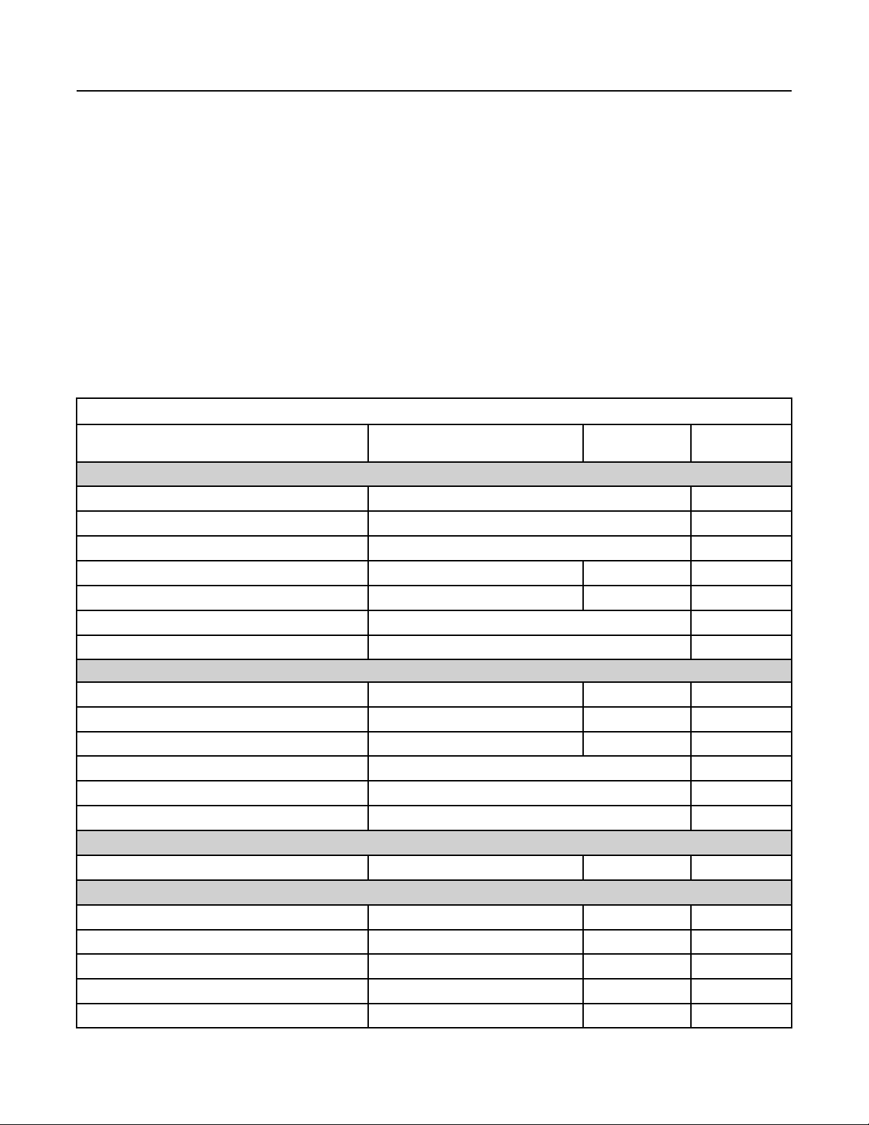
M0112246-02
Crank Terminate Speed
This parameter is used to define the desired engine
speed during engine cranking.
Digital Speed Control Min Speed
This parameter is used to configure the engine speed
below the rated speed of the engine.
Digital Speed Control Max Speed
This parameter is used to configure the engine speed
above the rated speed of the engine.
Parameter Table
Table 3
System Configuration Parameters
55
Operation Section
Configuration Parameters
Parameter
Selected Engine Ratings
Rating Number Software Dependent
Rated Frequency Software Dependent Read Only
Rated Engine Speed Software Dependent Read Only
Rated Real Genset Power
Rated Apparent Genset Power Kilowatts (if applicable) Rated power Read Only
Rating Configuration Software Dependent Read Only
Test Spec Software Dependent Read Only
ECM Identification Parameters
Equipment ID 17 alphanumeric characters
Engine Serial Number
ECM Serial Number
Software Group Part Number Software Dependent Read Only
Software Group Release Date Software Dependent Read Only
Software Group Description Software Dependent Read Only
Security Access Parameters
Total Tattletale 0 to 65535 0
Engine/Gear Parameters
Available Range or Options
Kilowatts (if applicable) Rated power Read Only
0XX00000 or XXX00000 Blank
Hardware Dependent
Default
Blank Customer
Blank
Required
Password
None
Factory
Read Only
Read Only
(1)
(1)
(1)
(1)
(1)
(1)
(1)
(1)
(1)
(1)
(1)
Engine Acceleration Rate 5 - 2000 rpm/sec
Low Idle Speed 600 to 1200 rpm
Engine Speed Droop
Droop/Isochronous Switch Enable
Droop mode selection Droop or Isochronous
0.0 - 8.0 % 3.0 % Customer
Enabled or Disabled Enabled Customer
500 Customer
1100 Customer
Isochronous Customer
(continued)
Page 56

56 M0112246-02
Operation Section
Configuration Parameters
(Table 3, contd)
System Configuration Parameters
Parameter
I/O Configuration Parameters
Ether Control Installed or Uninstalled Installed Customer
Air Inlet Heater Installed or Uninstalled Installed Customer
Engine Oil Temperature Sensor Installation Status
Desired Speed Input Configuration
Secondary Desired Speed Input Configuration
Fuel Enable Input Configuration
Secondary Fuel Enable Input Configuration
Fuel Filter Differential Pressure Switch Configuration
Emergency Shutdown Override Switch Installation Status
Emergency Shutdown Override Switch Configuration
Available Range or Options
Installed or Uninstalled Uninstalled Customer
PWM
CAN Input
0 - 5 VDC
PWM
CAN Input
0 - 5 VDC
Unistalled
Switch
J1939
Enabled or Disabled Enabled Customer
Uninstalled
Normally Open
Normally Closed
Installed or Uninstalled Uninstalled Customer
Switch to Ground
CAN Input
Default
CAN Input
CAN Input
Switch Customer
Uninstalled Customer
Switch to Ground Customer
Required
Password
Customer
Customer
System Parameters
FLS
FTS
Governor Gain Factor
Governor Minumum Stability Factor
Governor Maximum Stability Factor
Crank Terminate Speed 200 to 700 rpm
Digital Speed Control Min Speed 0 to 150 rpm
Digital Speed Control Max Speed 0 to 150 rpm
(1)
This parameter can be viewed only. No changes are allowed.
Programmed at the Factory Factory
Programmed at the Factory Factory
0 - 65,535 26,214
0 - 65,535
0 - 65,535
Customer
1049 Customer
2097 Customer
400 Customer
125 Customer
125 Customer
Page 57

M0112246-02
Parameter Worksheet
Table 4
Equipment ID
Engine Serial Number
ECM Serial Number
Software Group Part Number
Software Group Release Date
Software Group Description
FLS
FTS
Total Tattletale
Engine Acceleration Rate
57
Operation Section
Configuration Parameters
Parameter Worksheet
Engine Parameters
Low Idle Speed
Engine Speed Droop
Droop/Isochronous Switch Enable
Droop mode selection
Ether Control
Air Inlet Heater
Engine Oil Temperature Sensor Installation Status
Desired Speed Input Configuration
Secondary Desired Speed Input Configuration
Fuel Enable Input Configuration
Secondary Fuel Enable Input Configuration
Fuel Filter Differential Pressure Switch Configuration
Emergency Shutdown Override Switch Installation Status
Emergency Shutdown Override Switch Configuration
Governor Gain Factor
Governor Minumum Stability Factor
Governor Maximum Stability Factor
Crank Terminate Speed
Digital Speed Control Min Speed
Digital Speed Control Max Speed
Cylinder 1
Injector Serial Numbers
(continued)
Page 58

58 M0112246-02
Operation Section
Configuration Parameters
(Table 4, contd)
Parameter Worksheet
Cylinder 2
Cylinder 3
Cylinder 4
Cylinder 5
Cylinder 6
Information from the Engine Information Plate
Engine Serial Number
FLS
FTS
Note: Compare the FLS and the FTS from the ECM
with the values that are listed on the engine
information plate. Use of incorrect parameters could
cause damage to the engine. The use of the wrong
parameters may also void the Caterpillar warranty or
the emission certification for the engine.
Page 59

M0112246-02 59
Operation Section
Engine Starting
Engine Starting
i02354640
Before Starting Engine
SMCS Code: 1000; 1400; 1450
Perform the required daily maintenance and other
periodic maintenance before the engine is started.
Inspect the engine compartment. This inspection can
help prevent major repairs at a later date.
• For the maximum service life of the engine, make
a thorough inspection before starting the engine.
Look for the following items: oil leaks, coolant
leaks, loose bolts and trash buildup. Remove trash
buildup and arrange for repairs, as needed.
• Inspect the cooling system hoses for cracks and
for loose clamps.
• Inspect the alternator and accessory drive belts for
cracks, breaks, and other damage.
• Inspect the wiring for loose connections and for
worn wires or frayed wires.
• Check the fuel supply. Drain water from the water
separator (if equipped). Open the fuel supply
valve.
NOTICE
All valves in the fuel return line must be open before
and during engine operation to help prevent high fuel
pressure. High fuel pressure may cause filter housing
failure or other damage.
If the engine has not been run for several weeks, fuel
may have drained from the fuel system. Air may have
entered the filter housing. Also, when fuel filters have
been changed, some air space will be left in the
housing. In these instances, prime the fuel system.
Refer to the Operation and Maintenance Manual,
“Fuel System - Prime” for more information on
priming the fuel system.
• Ensure that the areas around the rotating parts are
clear.
• All of the guards must be put in place. Check for
damaged guards or for missing guards. Repair
any damaged guards. Replace damaged guards
and/or missing guards.
• Disconnect any battery chargers that are not
protected against the high current drain that is
created when the electric starting motor (if
equipped) is engaged. Check electrical cables and
check the battery for poor connections and for
corrosion.
• Reset any of the shutoff components or alarm
components.
• Check the engine lubrication oil level. Maintain the
oil level between the “ADD” mark and the “FULL”
mark on the oil level gauge.
• Check the coolant level. Maintain the coolant level
within 13 mm (0.5 inch) of the bottom of the filler
pipe. If the engine is equipped with a sight glass,
maintain the coolant level in the sight glass.
• Observe the air cleaner service indicator. Service
the air cleaner when the red target locks in the
visible position.
• Disengage any driven equipment. Remove any
electrical loads.
i05848852
Cold Weather Starting
SMCS Code: 1000; 1250; 1450; 1453; 1456; 1900
Note: Oil pan immersion heaters are not
recommended for heating the engine oil. To ensure
the compatibility of the components, only use
equipment that is recommended by Caterpillar.
Startability will be improved at temperatures below
16 °C (60 °F) with a starting aid. A jacket water
heater may be needed and/or the crankcase oil may
need warmed.
Engine exhaust contains products of combustion
which may be harmful to your health. Always
start and operate the engine in a well ventilated
area and, if in an enclosed area, vent the exhaust
to the outside.
• Do not start the engine or move any of the controls
if there is a “DO NOT OPERATE” warning tag or
similar warning tag attached to the start switch or
to the controls.
A jacket water heater is available as an option for
starting in temperatures as low as 0 °C (32 °F). The
jacket water heater can maintain the water
temperature at approximately 32 °C (90 °F). The
heated water will help to keep the oil in the engine
block warm enough to flow when the engine is
started.
Maintain the proper level of electrolyte in the
batteries. Keep the batteries fully charged.
Page 60

60 M0112246-02
Operation Section
Starting the Engine
To maximize the battery power, heat the battery
compartment or store the batteries in a warm
location. Typically, batteries only have 50 percent of
the capability at −10 °C (14 °F) versus 27 °C
(80 °F).
Extra battery capacity may be necessary for cold
temperatures.
When No. 2 diesel fuel is used, a fuel heater will
maintain the temperature of the fuel above the cloud
point. Fuel line insulation will help to maintain the fuel
temperature.
Consult your Caterpillar dealer for more information
on the starting aids that are available for cold weather
starting.
Starting With the Starting Aid
Switch (If Equipped)
Personal injury or property damage can result
from alcohol or starting fluids.
Alcohol or starting fluids are highly flammable
and toxic and if improperly stored could result in
injury or property damage.
4. Additional injections may be necessary in order to
start the engine. Additional injections may also be
necessary in order to achieve low idle. If additional
injections are necessary, toggle the Starting Aid
switch to the MANUAL position. For additional
injections, the jacket water coolant temperature
must be less than 10 °C (50 °F).
Note: The Starting Aid switch is a momentary switch.
To stop the injection, release the Starting Aid switch.
i07911112
Starting the Engine
(DSE6310 and DSE6320 Control
Modules)
SMCS Code: 1000; 1450
Note: The following descriptions detail the
sequences followed by a module containing the
standard factory configuration. Always refer to your
configuration sour for the exact sequences and
timers observed by any particular module in the field.
This section provides a quick start guide to the
operation of the module. For further details, see OEM
manual.
Excessive starting fluid can cause piston and ring
damage.
Use starting fluid for cold starting purposes only.
Do not use excessive starting fluid during starting or
after the engine is running.
The optional ether starting aid which is located
on the control panel is the only system that is
recommended for the injection of starting fluid.
1. Perform the procedures that are described in this
Operation and Maintenance Manual, “Before
Starting Engine”.
2. Press the “RUN” key.
3. Ether will automatically be injected if the following
conditions are met:
a. The Starting Aid switch is in the AUTOMATIC
position.
b. The jacket water coolant temperature is less
than 0 °C (32 °F).
NOTICE
Page 61
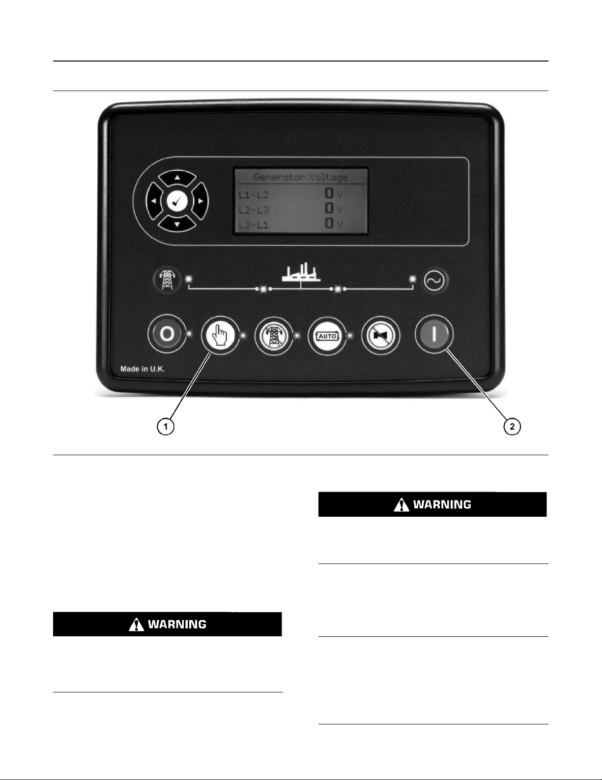
M0112246-02 61
Operation Section
DSE6310 and DSE6320 Control Modules
Illustration 42 g06476771
(1) Manual mode button (2) Start button
1. Press the “Manual Mode” button.
2. Press the “Start” button.
Note: If a digital input configured to “Panel Lock” is
active, changing module modes is not possible.
Viewing the instruments and event logs is not
When the engine is in the AUTOMATIC mode, the
engine can start at any moment. To avoid personal injury, always remain clear of the the engine
when the engine is in the AUTOMATIC mode.
affected by “Panel Lock” .
For further details about module configuration, refer
to For further details, see OEM manual.
Before manually starting the engine, perform all of
the procedures that are described in this Operation
and Maintenance Manual, “Before Starting Engine”.
Ensure that no one will be endangered before the
engine is started and when the engine is started.
Engine exhaust contains products of combustion
which may be harmful to your health. Always
start and operate the engine in a well ventilated
Do not engage the starting motor when flywheel is
turning. Do not start the engine under load.
NOTICE
area and, if in an enclosed area, vent the exhaust
to the outside.
If the engine fails to start within 30 seconds, release
the starter switch or button and wait two minutes to
allow the starting motor to cool before attempting to
start the engine again.
Page 62

62 M0112246-02
Operation Section
Starting with Jump Start Cables
For initial start-up of a new or rebuilt engine, and for
NOTICE
start-up of an engine that has been serviced, make
provision to shut the engine off should an overspeed
occur. This may be accomplished by shutting off the
air and/or fuel supply to the engine.
i03640789
Starting with Jump Start
Cables
SMCS Code: 1000; 1401; 1402; 1900
Improper jump start cable connections can cause
an explosion resulting in personal injury.
Prevent sparks near the batteries. Sparks could
cause vapors to explode. Do not allow jump start
cable ends to contact each other or the engine.
If the installation is not equipped with a backup
battery system, it may be necessary to start the
engine from an external electrical source.
2. Connect one positive end of the jump start cable to
the positive cable terminal of the discharged
battery. Connect the other positive end of the jump
start cable to the positive cable terminal of the
charging or starting source.
3. Connect one negative end of the jump start cable
to the negative cable terminal of the charging or
starting source. Connect the other negative end of
the jump start cable to the stalled engine block or
to the chassis ground. This procedure helps to
prevent potential sparks from igniting combustible
gases that are produced by some batteries.
4. Charge the batteries. The engine will not continue
to run after starting if the batteries have not been
charged.
5. Start the engine.
6. Immediately after the stalled engine is started,
disconnect the jump start cables in reverse order.
Refer to the Electrical Schematic for your engine.
Consult your Caterpillar dealer for more information.
i02369353
For information on troubleshooting the charging
system, refer to Special Instruction, REHS0354,
“Charging System Troubleshooting”.
Many batteries which are considered unusable are
still rechargeable. After jump starting, the alternator
may not be able to fully recharge batteries that are
severely discharged. The batteries must be charged
to the proper voltage with a battery charger. For
information on testing and charging, refer to the
Special Instruction, SEHS7633, “Battery Test
Procedure”.
NOTICE
Use a battery that is sourced with the same voltage
as the electric starting motor. Use ONLY equal voltage for jump starting. The use of higher voltage will
damage the electrical system.
Do not reverse the battery cables. The alternator can
be damaged. Attach the negative battery cable last
and remove the negative battery cable first.
When an external electrical source is used to start
the engine, turn the control switch on the generator
set to the “OFF” position. Turn all electrical accessories OFF before attaching the jump start cables.
Ensure that the main power switch is in the OFF position before jump start cables are attached to the engine that is being started.
After Starting Engine
SMCS Code: 1000
After the engine has been installed or rebuilt,
carefully monitor the engine in order to detect any
unusual engine performance.
Warm-up
1. Operate the engine at low idle for two to three
minutes. Allow the jacket water coolant
temperature to begin to rise before increasing the
engine rpm to rated rpm.
Note: More warm-up time may be necessary when
the ambient temperature is below −18 °C (0 °F).
2. Check all of the indicators during the warm-up
period.
3. Make another walk-around inspection. Inspect the
engine for fluid leaks and air leaks.
The time that is needed for the engine to reach the
normal mode of operation is usually less than the
time that is needed for a walk-around inspection.
1. Turn the start switch on the stalled engine to the
OFF position. Turn off all accessories.
Page 63

M0112246-02 63
Operation Section
After Starting Engine
The engine will reach normal operating temperature
faster when the engine is operated at rated rpm and
low power demand. This procedure is more effective
than idling the engine with no load. The engine
should reach normal operating temperature in a few
minutes.
Engaging the Generator
1. Ensure that the indicators are in the normal ranges
for the engine rpm.
2. Increase the engine rpm to rated rpm. Always
increase the engine speed to rated rpm before
applying the load.
3. Adjust the voltage and the frequency, if necessary.
4. Close the main circuit breaker in order to apply the
load.
5. Continue to check the indicators and the
generator.
Page 64

64 M0112246-02
Operation Section
Engine Operation
Engine Operation
i07540591
Engine Operation
(Hydrocarbon Mitigation)
SMCS Code: 1000
Proper operation and maintenance are key factors in
obtaining the maximum life and economy of the
engine. If the directions in the Operation and
Maintenance Manual are followed, costs can be
minimized and engine service life can be maximized.
The time that is needed for the engine to reach
normal operating temperature can be less than the
time taken for a walk-around inspection of the
engine.
The engine can be operated at the rated rpm after
the engine is started and after the engine reaches
operating temperature. The engine will reach normal
operating temperature sooner during a low engine
speed (rpm) and during a low-power demand. This
procedure is more effective than idling the engine at
no load. The engine should reach operating
temperature in a few minutes.
Gauge readings should be observed and the data
should be recorded frequently while the engine is
operating. Comparing the data over time will help to
determine normal readings for each gauge.
Comparing data over time will also help detect
abnormal operating developments. Significant
changes in the readings should be investigated.
Hydrocarbon Mitigation
The hydrocarbon mitigation is a feature to protect the
DOC against temperatures below 325° C (617° F).
Temperatures below this range can damage the
aftertreatment of the machine. The initial occurrence
displays as a warning and then if temperatures do not
increase by the operator or strategy, the machine will
go into shutdown. Messages appear sequentially as
follows:
• First : Key cycle to warning
• Secondary : Warning to shut down
If the warning messages are not acknowledged, then
the shutdown counter begins. Once the engine has
shutdown for low exhaust temperatures, the 173-18
Engine Exhaust Manifold #1 Temperature #1: Low Moderate Severity (2) will return until the engine has
successfully reached target temperatures.
Once exhaust temperatures below 325° C (617° F)
are observed for an hour, the Hydrocarbon Mitigation
feature begins and the following conditions below
become active.
Cylinder Cutout Strategy
The cylinder cutout starts at 1000 rpm. The
hydrocarbon mitigation monitors the exhaust and
intake target temperatures and increases speed if
temperatures are not achieved in intervals. The
intervals are 20 minutes and with 200 rpm
increments. The speed range for the strategy is 1000
rpm to 1800 rpm with a minimum run time of 100
minutes.
Note: This strategy only runs in non-work mode.
The strategy success criteria is based on the
following:
• Intake air manifold temperature over 10° C (50° F)
• Exhaust manifold temperature over 325° C
(617° F)
If successful, the machine will continue to run
indefinitely at the current rpm until taken out of non-
work mode.
Exhaust Temperature Low Code Actions
Once the 173-18 Engine Exhaust Manifold #1
Temperature #1: Low - Moderate Severity (2)
warning message is shown, there are two actions the
can be taken to remove them:
Non-Work Mode
Put the machine in Non-Work mode.
• This will allow Hydrocarbon Mitigation to start
automatically and attempt to achieve the target
temperatures for the intake and exhaust.
• If the strategy does not achieve target
temperatures, the engine will return to low idle for
60 minutes and then Hydrocarbon Mitigation
begins.
• If the strategy continues to fail, the next action will
need to be taken to clear the codes.
Non-Work Mode Failure
If the machine is being used at the time of the
warning message and cannot be put into Non-Work
mode, then raise the intake and exhaust temperature
for their time thresholds.
• Intake air manifold temperature is greater than
10° C (50° F) for 10 minutes continuously
• Exhaust manifold temperature is greater than
325° C (617° F) for 30 minutes continuously
• Blender - Ideal time to perform this is during the 60
minute low time after a Hydrocarbon Mitigation
failure.
Page 65

M0112246-02 65
Operation Section
Fuel Conservation Practices
Note: Hydrocarbon Mitigation will always start
mitigation.
Partial Load Operation
Extended operation at reduced load (less than 30%)
may cause increased oil consumption and carbon
buildup in the cylinders. Extended operation at
reduced load may also cause fuel to slobber through
the exhaust system. A loss of power and/or poor
performance may result.
To maintain engine efficiency and performance, apply
70% load to the engine on an hourly basis. Operating
the engine at a load level that is greater than 30% will
also maintain engine efficiency and performance.
This action will burn excess carbon from the
cylinders.
i04289968
Fuel Conservation Practices
SMCS Code: 1000; 1250
The efficiency of the engine can affect the fuel
economy. The design and technology used
byCaterpillar in manufacturing provides maximum
fuel efficiency in all applications. Follow the
recommended procedures in order to attain optimum
performance for the life of the engine.
• Ensure that the driven equipment is in good
working order.
• Cold engines consume excess fuel. Keep cooling
system components clean and keep cooling
system components in good repair. Never operate
the engine without water temperature regulators.
All of these items will help maintain operating
temperatures.
• Settings for the fuel system and the limits for the
operating altitude are stamped on the Engine
Information Plate. If an engine is moved to a
higher altitude, the settings must be changed by a
Cat dealer. Changing the settings will help to
provide the maximum efficiency for the engine.
Engines can be operated safely at higher
altitudes, but the engines will deliver less
horsepower. The fuel settings should be changed
by a Cat dealer in order to obtain the rated
horsepower.
• Avoid spilling fuel.
Fuel expands when the fuel is warmed up. The fuel
may overflow from the fuel tank. Inspect fuel lines for
leaks. Repair the fuel lines, as needed.
• Be aware of the properties of the different fuels.
Use only the recommended fuels.
• Avoid unnecessary operation at no load.
Shut off the engine instead of operating the engine at
no load for long periods of time.
• Observe the service indicator for the air cleaner
frequently, if equipped. Keep the air cleaner
elements clean.
• Do not remove the cover for the air cleaner unless
the air filter service indicator indicates the need for
cleaning of the filter.
• Maintain a good electrical system.
One bad battery cell will overwork the alternator. This
will consume excess power and excess fuel.
• Ensure that the belts are properly adjusted. The
belts should be in good condition.
• Ensure that all of the connections of the hoses are
tight. The connections should not leak.
Page 66
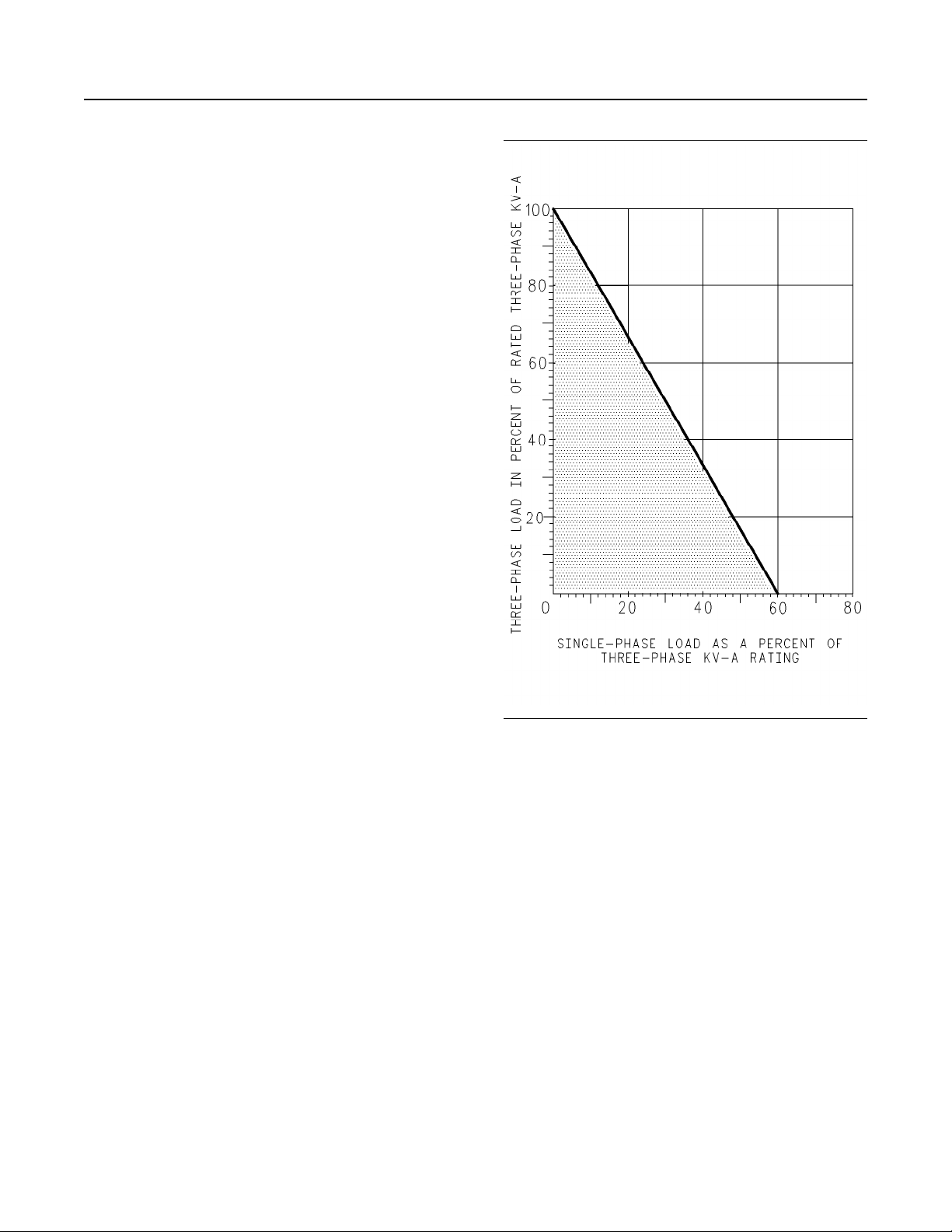
66 M0112246-02
Operation Section
Generator Operation
Generator Operation
i02309602
Generator Operation
SMCS Code: 4450
Loading of the Generator
When a generator is installed or reconnected, be
sure that the total current in one phase does not
exceed the nameplate rating. Each phase should
carry the same load. This allows the engine to work
at the rated capacity. An electrical unbalance can
result in an electrical overload and overheating if one
phase current exceeds the nameplate amperage.
Allowable combinations of unbalanced loads are
shown in Illustration 43 . When you operate with
significant single-phase loads, the combinations of
single-phase load and three-phase load may be
used. Such combinations should be located below
the line on the graph.
Illustration 43 g00627416
Allowable Combinations of Unbalanced Loads
Block Loading
When an electrical load is applied to a generator set,
block loading occurs. This load may be anywhere
from a moderate percentage of the rated load up to
the rated load.
The block loading capability of a generator set
depends on the following factors:
• Engine transient response
• Voltage regulator response
• Type of the voltage regulator
• Altitude of operation of the generator set
• Type of load
• The amount of load that is already present
Page 67

M0112246-02 67
Operation Section
Generator Operation
If a block load derating is required, refer to ISO 8528
Standards or SAE J1349 Standards. Also, reference
Engine Data Sheet, LEKX4066, “Loading Transient
Response” and Engine Data Sheet, LEKX4067,
“Block and Transient Response”.
Power Factor
Power factor (PF) determines the relationship
between true power and apparent power. The true
power is also known as the active power. The
apparent power is also called kVA. The true power
(kW) is the work that is done on the load by the
engine. The true power determines the amount of
power that is available for the load to do work. The
apparent power (kVA) is the total power that is
produced by the generator. Power factor can be
calculated by using the following formula.
PF = kW / kVA,
kW – kilowatts
kVA – Kilo-Volt-Ampere
KVAR stands for Kilo-Volt-Ampere-Reactive, which is
the unit of measurement for reactive power.
Note: The generator does NOT control power factor.
Power factor is determined by the load.
In most applications, electric motors, solid-state
controls, and transformers determine the power
factor of the system. Induction motors usually have a
power factor that is no larger than 0.8. Incandescent
lighting is a resistive load of about 1.0 power factor,
or unity. Solid-state controls, variable frequency
drivers (VFD), variable speed drivers (VSD), and
systems for the UPS can operate at any power factor,
leading or lagging. In this case, the power factor can
be between 0.4 and 1.0.
The power factor of a system may be determined by
a power factor meter or by calculations. Determine
the power requirement in kW by multiplying the
power factor by the kVA that is supplied to the
system. As the power factor increases, the total
current that is supplied to a constant power demand
will decrease. With equal loads, a lower power factor
will draw more current. A high power factor will result
in full engine load that is less than the generator's
rated amperage. A lower power factor increases the
possibility of overloading the generator.
Note: Normally, Caterpillar generators are designed
for a power factor of 0.8 lagging. Please consult your
Caterpillar dealer in order to check the generator
rating if the operation at less than 0.7 lagging power
factor or operation at a leading power factor of 0.8 is
desired.
Excitation Systems
Refer to the Operation and Maintenance Manual,
“Voltage Regulators” for information on excitation
systems.
Low Idle Adjustment
The low idle is typically 1200 rpm. On 60 Hz units,
low idle will be approximately 66 percent of the full
load speed. On 50 Hz units, low idle will be
approximately 80 percent of full load speed.
The low idle is set at the factory on generator sets
with mechanical governors. The low idle should only
be adjusted by your Caterpillar dealer if adjustment is
required.
Note: Operating the electric set at low idle speed for
an extended time will cause some voltage regulators
to shut off. The electric set must be completely shut
down. Then, the electric set must be restarted. This
will allow the voltage regulator to again produce an
output.
Standby Generator Sets
Most standby units are automatic. Without an
operator in attendance, standby units will perform the
following functions: start, pick up the load, run and
stop.
Standby units will not change the governor speed
control or voltage level settings automatically. The
governor speed and voltage level must be preset for
the proper operation of that unit. Whenever the set is
operated manually, ensure that the governor speed
and the voltage level settings are set correctly for
automatic operation. Check all switches for the
proper setting. The Engine Control Switch should be
in the AUTOMATIC position. Emergency Stop
Switches should be in RUN position.
Generator Options
Space Heaters
Most of the generators are provided with space
heaters. These space heaters are installed for
operation in all climates. For more information on
space heaters, refer to Maintenance Section, “Space
Heater - Check”.
Page 68

68 M0112246-02
Operation Section
Single Unit Operation
Embedded Temperature Detectors
Some generators are available with embedded
temperature detectors. The detectors are installed in
the slots of the main armature. The main armature is
also called a stator. The detectors are used with the
equipment that is provided by the customer. Thus,
the temperature of the main armature winding can be
measured or monitored. RTDtemperature detectors
are available. Contact your Caterpillar dealer for
more information.
Bearing Temperature Detectors
Bearing temperature detectors are available on
large-frame generators. Bearing temperature
detectors measure the main bearing temperature.
Thus, the temperature of the bearing can be
measured or monitored. Bearing temperature
measurements may help to prevent premature
bearing failure. Bearing temperature detectors are
used with customer provided equipment. Contact
your Caterpillar dealer for more information.
i07911802
Single Unit Operation
SMCS Code: 4450
6. Apply the load. Do not try to apply the full load.
Apply the load in increments to maintain system
frequency at a constant level.
7. Readjust the governor for rated frequency.
Adjust the Voltage
Use the following procedure to adjust the voltage and
frequency of the generator output.
1. From the “MAIN MENU” , use the down navigation
key (15) or the up navigation key (12) to navigate
to the “CONTROL” menu.
a. Press the “OK” key (14) to select the
“CONTROL” menu. “VOLT/HZ CONTROL” will
be displayed.
Note: The voltage can be controlled from the
control module over CAN data link, discrete
outputs, or analog outputs. The speed can only be
controlled if there is an ADEM on the engine.
b. Press the “OK” key (14).
c. Press the up navigation key (12) to increase the
voltage and press the down navigation key (15)
to decrease the voltage.
Initial Start-Up
Measure the insulation resistance of each winding if
the generator was exposed to the following
conditions:
• Rapid changes in temperature
• Freezing
• Wet climate during shipment
• Wet climate during storage
Refer to this Operation and Maintenance Manual,
“Insulation - Test”.
Note: These tests should be conducted prior to any
power connections or control connections that are
being made.
Starting
1. Make all preliminary engine starting checks.
2. Be sure that the main circuit breaker or the line
circuit breaker is open.
3. Start the engine. Allow the engine to warm up.
Note: When adjusting the voltage using the
navigation keys, an offset is applied to the set point
value for “GENERATOR NOMINAL OUTPUT
VOLTAGE” . The set point is transmitted over the
Primary CAN data link to the voltage regulator and
is retained until battery power is cycled to the
control module. Cycling the battery power to the
control module will remove the offset. Once the
offset is removed, the transmitted value reverts to
the set point value for “GENERATOR NOMINAL
OUTPUT VOLTAGE” .
d. Press the left navigation key (16) to decrease
the engine speed. Press the right navigation
key (13) to increase the engine speed.
Note: When the left and right navigation keys are
used to adjust the frequency, an offset is applied to
the set point value for “GENERATOR NOMINAL
OUTPUT FREQUENCY” . This data is transmitted
over the Primary CAN data link to the engine
controller and is retained until battery power is
cycled to the control module. Cycling the battery
power to the control module will remove the offset.
Once the offset is removed, the transmitted value
reverts to the set point value for “GENERATOR
NOMINAL OUTPUT FREQUENCY” .
4. Adjust to the full load engine speed.
5. Close the main circuit breaker.
Page 69

M0112246-02 69
Operation Section
Parallel Operation
Note: Unlike the setpoints or preferences, for
instance contrast, any changes to this screen takes
effect immediately. The “OK” key and escape key
will not save or cancel changes.
Stopping
1. Remove the load in increments.
2. Open the circuit breaker.
3. Press the “Stop/Reset Mode” button as described
in the Manual Stop Procedure section of this
Operation and Maintenance Manual.
4. Allow the engine to run for at least 3 minutes to
cool. The control module will shut down the engine
after cool down time has been reached.
i07916155
Parallel Operation
SMCS Code: 4450
For detailed information about paralleling, see
Special Instruction, UENR8557, “D350 Digital
Voltage Regulator”.
i05469037
Voltage Regulators
SMCS Code: 4467
D350 Digital Voltage Regulator
The purpose of this voltage regulator is to regulate
alternators with a field current of less than 5A in
continuous operations, and 10A maximum in the
event of short-circuit for 10 seconds maximum.
The design is in accordance with mounting in a
generator terminal box, or a control cabinet. At a
minimum, following the local protection and safety
standards is required, especially those standards
specific to electrical installations for voltages of 300
VAC phase-to-neutral maximum.
Page 70
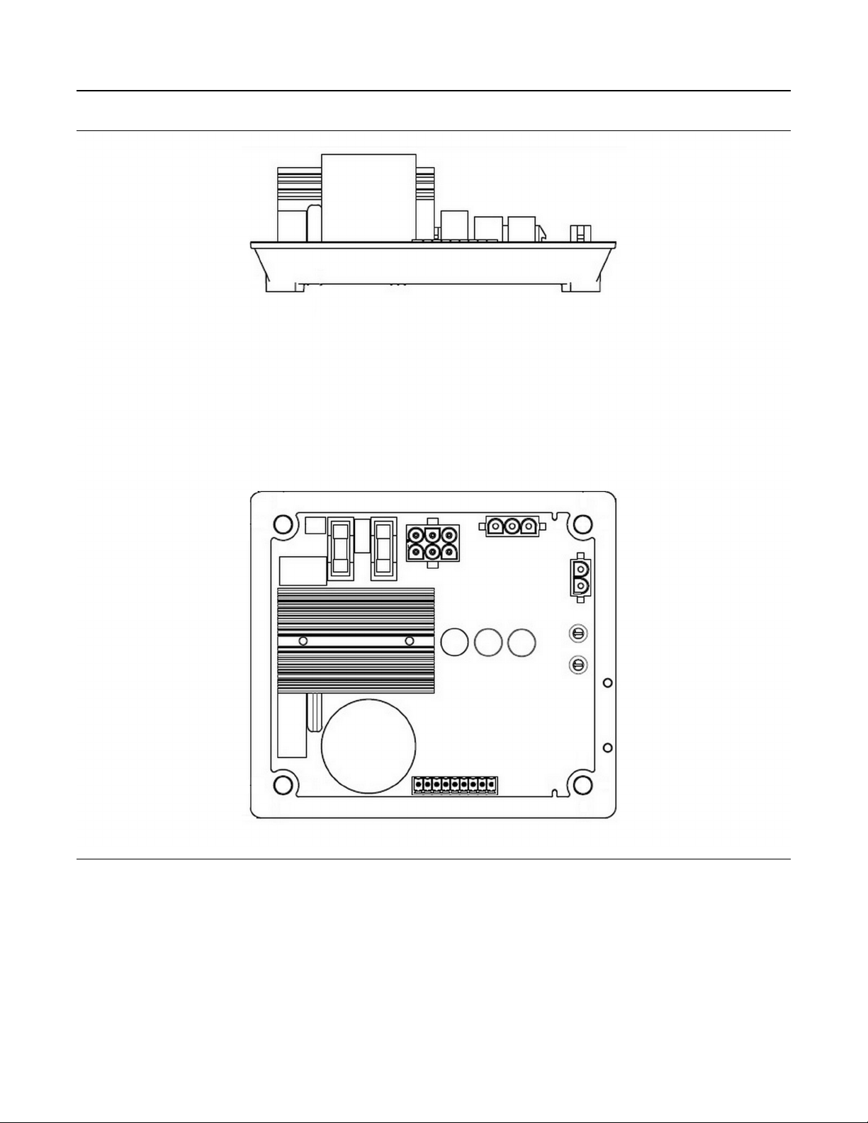
70 M0112246-02
Operation Section
Voltage Regulators
Illustration 44 g06476083
D350
Page 71
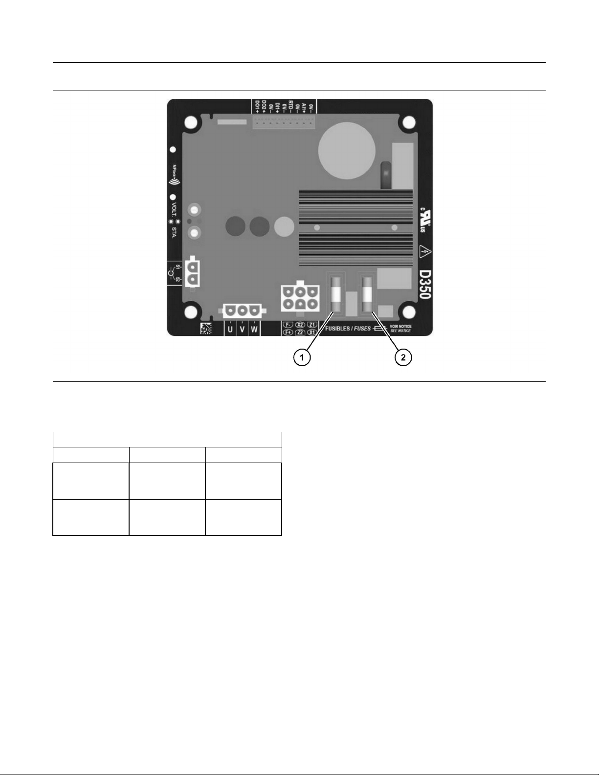
M0112246-02 71
Operation Section
Voltage Regulators
Illustration 45 g06475852
(1) F1 (2) F2
Table 5
Fuse References
F1 F2
In standard 10A, 250V ref.
Mersen Q206071T
or equivalent
For UL
applications
8A, 250V ref. Mers-
en T084013T or
equivalent
10A, 250V ref.
Mersen Q206071T
or equivalent
10A, 250V ref.
Mersen Q206071T
or equivalent
Similar to other AVR, the D350 is an electronic
printed circuit board, protected with a polyurethane
resin as shown in figure 45 .
For more information about D350, see Special
Instruction, “D350 Digital Voltage
Regulator”UENR8557.
Near Field Communication (NFC)
Configuration Module
The D350 is equipped with NFC technology for
communication and configuration purposes. For
specific information about how to configure this
feature on D350, refer to Special Instruction,
UENR8557, “D350 Digital Voltage Regulator” NFLink
Configuration Module.
Page 72
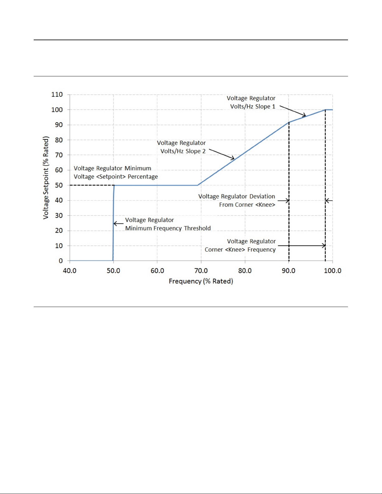
72 M0112246-02
Operation Section
Voltage Regulators
Excitation
Illustration 46 g03487998
Under-frequency (loading) profile (In this example slope1 = 1.0 V/Hz, slope2 = 2.0 V/Hz)
Page 73
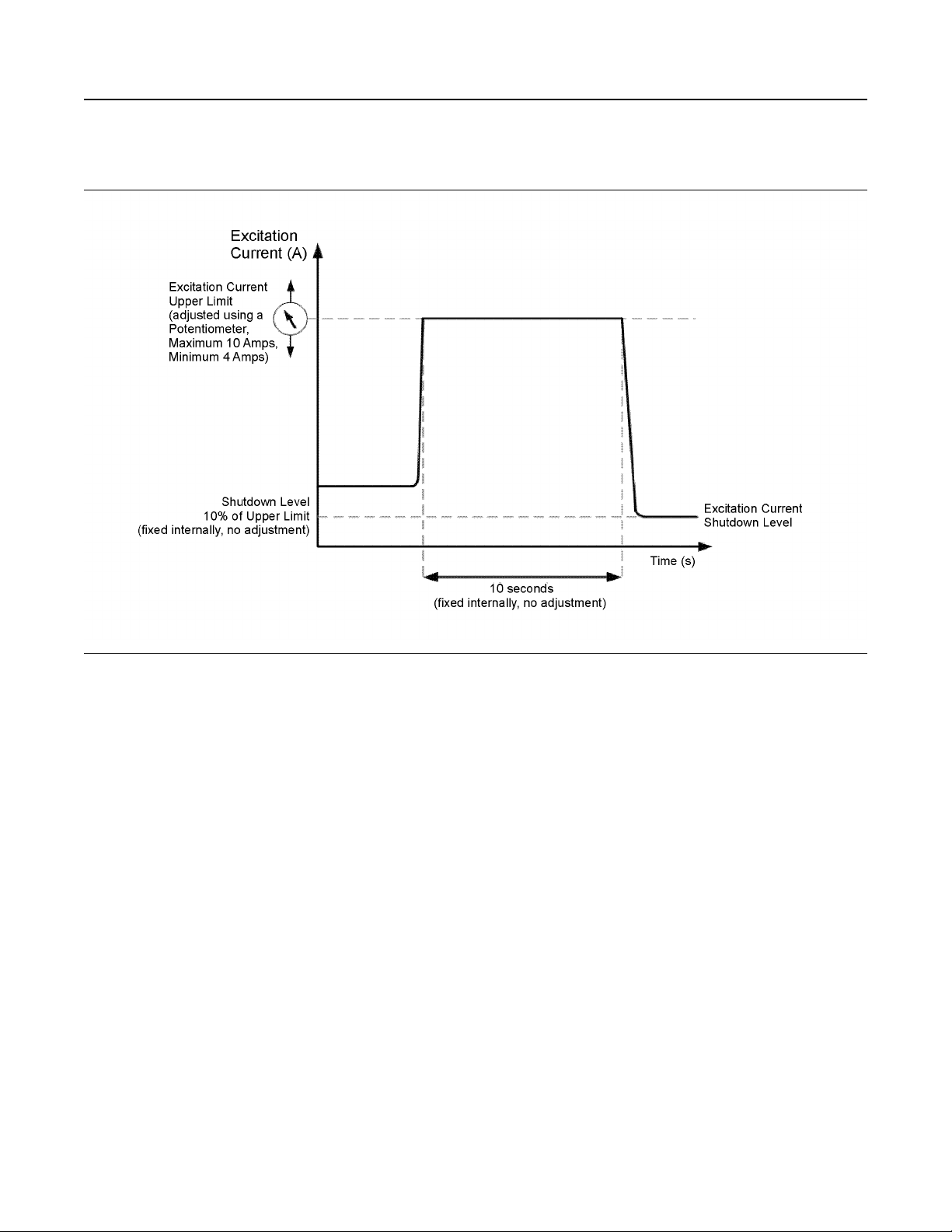
M0112246-02 73
Operation Section
Voltage Regulators
Over-Excitation Protection
Illustration 47 g03457278
• If a short-circuit fault occurs at the generator
terminals, the EM10 will allow the excitation
current to rise to the upper limit value set by the
adjustment potentiometer (maximum 10 Amps)
• The excitation current will be clamped at the upper
limit value for 10 seconds (fixed internally)
• After 10 seconds, the excitation current is reduced
to a value of 10% of the potentiometer setting
For more information about EM10, contact your Cat
dealer.
Page 74

74 M0112246-02
Operation Section
Cold Weather Operation
Cold Weather Operation
i08230315
Fuel and the Effect from Cold
Weather
SMCS Code: 1000; 1250; 1280
The following fuels are the grades that are available
for Cat engines:
• No. 1
• No. 2
• Blend of No. 1 and No. 2
No. 2 diesel fuel is the most commonly used fuel.
Either No. 1 diesel fuel or a blend of No. 1 and No. 2
is best suited for cold-weather operation.
Quantities of No. 1 diesel fuel are limited. No. 1
diesel fuels are available during the months of the
winter in the colder climates. During cold-weather
operation, if No. 1 diesel fuel is not available, use No.
2 diesel fuel, if necessary.
There are three major differences between No. 1 and
No. 2 diesel fuel. No. 1 diesel fuel has the following
properties:
• Lower cloud point
• Lower pour point
• Lower rating of kJ (BTU) per unit volume of fuel
When No. 1 diesel fuel is used, a decrease in power
and in fuel efficiency may be noticed.
• Engine oil pan heaters
• Engine coolant heaters
• Fuel heaters
• Fuel line insulation
For more information on cold-weather operation, see
Special Publication, SEBU5898, “Cold-Weather
Recommendations”.
i04369188
Fuel Related Components in
Cold Weather
SMCS Code: 1000; 1250; 1280
Fuel Tanks
Condensation can form in partially filled fuel tanks.
Top off the fuel tanks after operating the engine.
Fuel tanks should contain some provision for draining
water and sediment from the bottom of the tanks.
Some fuel tanks use supply pipes that allow water
and sediment to settle below the end of the fuel
supply pipe.
Some fuel tanks use supply lines that take fuel
directly from the bottom of the tank. If the engine is
equipped with this system, regular maintenance of
the fuel system filter is important.
Draining the fuel tank will help prevent water and/or
sediment from being pumped from the fuel storage
tank and into the engine fuel tank. Drain the water
and sediment from any fuel storage tank at the
following intervals:
The cloud point is the temperature when a cloud of
wax crystals begins to form in the fuel. These crystals
can cause the fuel filters to plug. The pour point is the
temperature when diesel fuel will thicken. The diesel
fuel becomes more resistant to flow through fuel
pumps and through fuel lines.
Be aware of these values when diesel fuel is
purchased. Anticipate the average ambient
temperature of the area. Engines that are fueled in
one climate may not operate well if the engines are
moved to another climate. Problems can result due to
changes in temperature.
Before troubleshooting for low power or for poor
performance in the winter, check the type of fuel that
is being used.
When No. 2 diesel fuel is used, the following
components provide a means of minimizing problems
in cold weather:
• Starting aids
• Weekly
• Oil changes
• Refueling of the fuel tank
Fuel Filters
NOTICE
Do not fill the fuel filters with fuel before installing
them. The fuel would not be filtered and could be con-
taminated. Contaminated fuel will cause accelerated
wear to fuel system parts.
NOTICE
Caterpillar requires the use of a 4 micron (c) secondary fuel filter for the following reasons: to maximize
fuel system life and to prevent premature wear out
from abrasive particles in the fuel. Cat high efficiency
fuel filters meet these requirements. Consult your Cat
dealer for the proper part numbers.
Page 75

M0112246-02
When the engine is equipped with a primary filter/
water separator, the primary filter/water separator
must use a 10 micron filter to a 15 micron filter. The
filters are becoming more critical as fuel injection
pressures increase to 209 MPa (30000 psi) and
higher psi. For more information on priming the fuel
system, see the Operation and Maintenance Manual,
“Fuel System - Prime” topic.
Fuel Heaters
Fuel heaters help to prevent fuel filters from plugging
in cold weather due to waxing. A fuel heater should
be installed in order for the fuel to be heated before
the fuel enters the primary fuel filter.
Select a fuel heater that is mechanically simple, yet
adequate for the application. The fuel heater should
also help to prevent overheating of the fuel. High fuel
temperatures reduce engine performance and the
availability of engine power. Choose a fuel heater
with a large heating surface. The fuel heater should
be practical in size. Small heaters can be too hot due
to the limited surface area.
75
Operation Section
Fuel Related Components in Cold Weather
Disconnect the fuel heater in warm weather.
Note: Only use fuel heaters that are controlled by the
water temperature regulator or fuel heaters that are
self-regulating. Fuel heaters that are not controlled by
the water temperature regulator can heat the fuel in
excess of 65° C (149° F). A loss of engine power can
occur if the fuel supply temperature exceeds 37° C
(100° F).
Note: Heat exchanger type fuel heaters should have
a bypass provision in order to prevent overheating of
the fuel when the engine operates in warm weather.
For further information on fuel heaters, consult your
Cat dealer.
Page 76
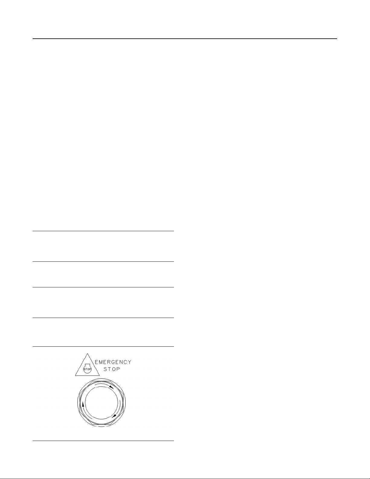
76 M0112246-02
Operation Section
Engine Stopping
Engine Stopping
i01895736
Stopping the Engine
SMCS Code: 1000
Note: Individual applications will have different
control systems. Ensure that the shutoff procedures
are understood. Use the following general guidelines
in order to stop the engine.
1. Remove the load from the engine. Reduce the
engine speed (rpm) to low idle. Perform this
procedure for five to six minutes in order to cool
the engine.
2. After the cool down period, move the switch to the
OFF position.
i02237582
Emergency Stopping
SMCS Code: 1000; 7418
The emergency stop button is in the OUT position for
normal engine operation. Push the emergency stop
button. The engine will not start when the button is
locked. Turn the button clockwise in order to reset.
i07911201
Emergency shutoff controls are for EMERGENCY
use ONLY. DO NOT use emergency shutoff devices
or controls for normal stopping procedure.
Ensure that any components for the external system
that support the engine operation are secured after
the engine is stopped.
Do not start the engine until the problem necessitating the emergency stop has been located and
corrected.
NOTICE
NOTICE
Emergency Stop Button
Illustration 48 g00104303
Typical emergency stop button
Page 77
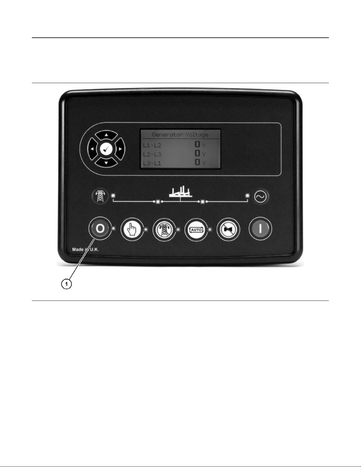
M0112246-02
Manual Stop Procedure
SMCS Code: 1000; 7418
77
Operation Section
Manual Stop Procedure
Illustration 49 g06476789
(1) Stop/reset mode button
Note: If a digital input configured to “Panel Lock” is
active, changing module modes is not possible.
Viewing the instruments and event logs is not
affected by “Panel Lock” .
For further details about module configuration, refer
to OEM manual.
In “Stop/Reset Mode” the module removes the
generator from load (if necessary) before stopping
the generator set.
If the generator does not stop when requested, the
“Fail to Stop” alarm is activated (subject to the setting
of the “Fail to Stop” timer. To detect the engine at
rest, the following must occur:
• Engine speed is zero as detected by the “CAN
ECU”
• Generator AC voltage and frequency must be zero
• Engine charge alternator voltage must be zero
• Oil pressure sensor must indicate low oil pressure
When the engine has stopped and the module is in
the “Stop/Reset Mode” , configuration files can be
sent to the module from “DSE Configuration Suite PC
software” . Entering the “Front Panel Editor” to
change parameters is also possible.
Any latched alarms that have been cleared are reset
when “Stop/Reset Mode” is entered.
The engine is not started when in “Stop/Reset Mode”
. If start signals are given, the input is ignored until
“Auto Mode” is entered.
Page 78

78 M0112246-02
Operation Section
After Stopping Engine
When left in “Stop/Reset Mode” without pressing any
buttons, no form of communication active/configured
for “Power Save Mode” , the module enters “Power
Save Mode” . To wake the module, press any of the
DSE buttons.
i02327953
After Stopping Engine
SMCS Code: 1000
• Check the engine crankcase oil level. Maintain the
oil level between the “ADD” and “FULL” marks on
the “ENGINE STOPPED” side of the oil level
gauge. Complete all of the lubrication
recommendations that are listed in Special
Publication, SEBU6251, “Caterpillar Commercial
Diesel Engine Fluids Recommendations”.
• If necessary, perform minor adjustments. Repair
any leaks and tighten loose bolts.
• Note the service hour meter reading. Perform the
maintenance that is in the Operation and
Maintenance Manual, “Maintenance Interval
Schedule”.
• Fill the fuel tank in order to help prevent
accumulation of moisture in the fuel. Do not overfill
the fuel tank.
Note: Only use the antifreeze coolant solutions that
are recommended in Special Publication,
SEBU6251, “Caterpillar Commercial Diesel Engine
Fluids Recommendations”. Failure to follow the
recommendations in Special Publication, SEBU6251,
“Caterpillar Commercial Diesel Engine Fluids
Recommendations” can cause engine damage.
• Allow the engine to cool. Check the coolant level.
Maintain the cooling system at 13 mm (0.5 inch)
from the bottom of the pipe for filling.
• If freezing temperatures are expected, check the
coolant for proper antifreeze protection. The
cooling system must be protected against freezing
to the lowest expected outside temperature. See
Special Publication, SEBU6251, “Caterpillar
Commercial Diesel Engine Fluids
Recommendations”. Add the proper coolant/water
mixture, if necessary.
Page 79
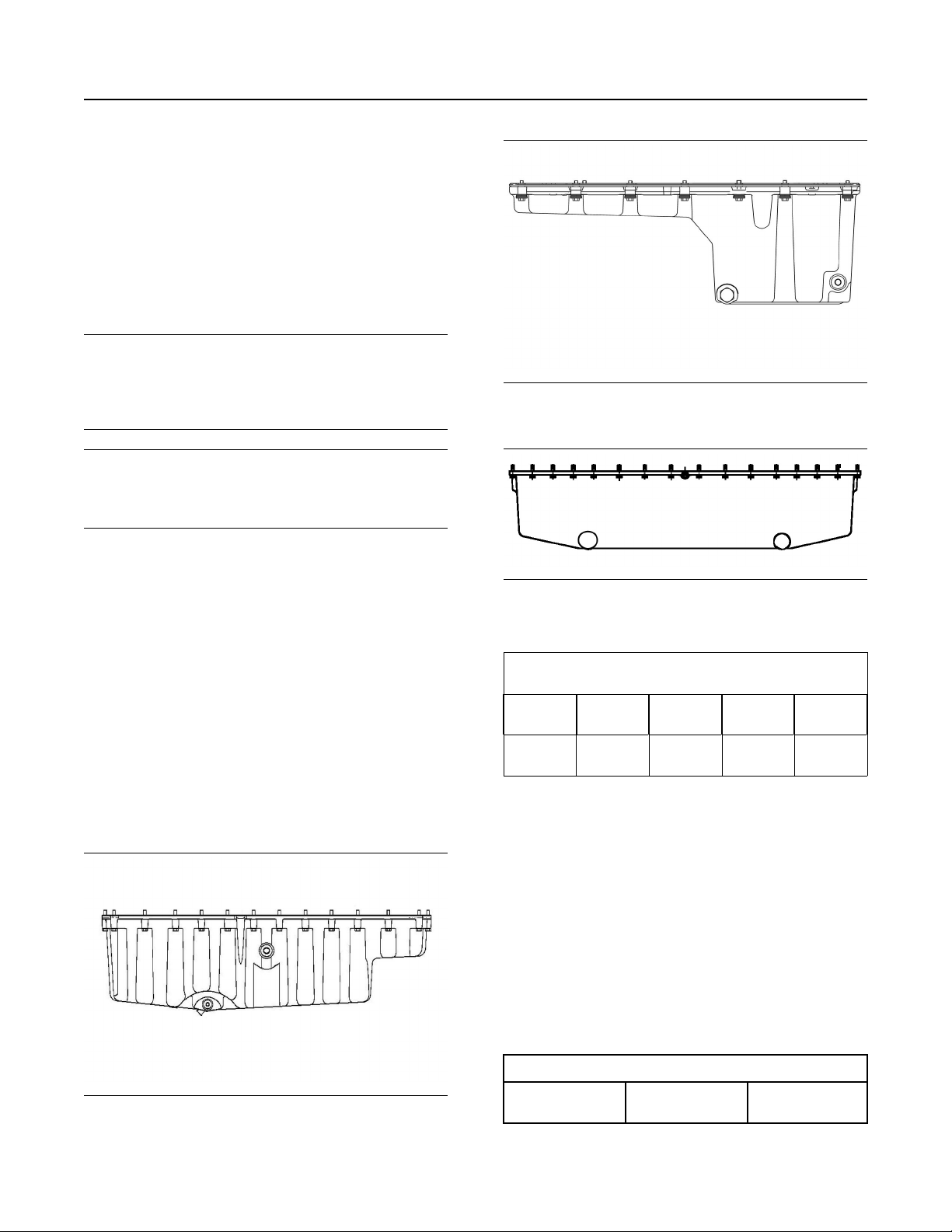
M0112246-02 79
Maintenance Section
Refill Capacities
Maintenance Section
Refill Capacities
i07920055
Refill Capacities
SMCS Code: 1000; 1348; 1395; 7560
Every attempt is made to provide accurate, up-to-
NOTICE
date information. By the use of this document, you
agree that Caterpillar Inc. is not responsible for errors
or omissions.
NOTICE
These recommendations are subject to change without prior notice. Contact your Caterpillar dealer for
the most up to date recommendations.
Refer to Special Publication, SEBU6251, “Caterpillar
Commercial Engine Fluids Recommendations” for
additional information.
Refer to this Operation and Maintenance Manual,
“Severe Service Application – Check” for information
about operating an engine in a severe service
application.
Diesel Engine Oil
The refill capacities for the engine crankcase reflect
the approximate capacity of the crankcase or sump
plus standard oil filters. Auxiliary oil filter systems will
require additional oil. Refer to the OEM specifications
for the capacity of the auxiliary oil filter. Refer to this
Operation and Maintenance Manual, “Fluid
Recommendations” for information about the types of
fluids for use in the engine.
Illustration 51 g06489025
Oil pan for the C13
Illustration 52 g02109598
Oil pan for the C15 and C18
Table 6
Approximate Refill Capacities
Engine
model
Engine
crankcase
(1)
These values are approximate capacities for the crankcase oil
sump which include the standard oil filters that are installed at
the factory. Engines with auxiliary oil filters will require additional oil. Refer to the OEM specifications for the capacity of the
auxiliary oil filter.
C9 C13
41 L
(43.3 qt)
Engine
(1)
40 L
(42.30 qt)
C15 C18
64 L
(67.6 qt)
68 L
(71.9 qt)
Illustration 50 g06489042
Oil pan for the C9
For more information about lubricants, refer to
Special Publication, SEBU6251, “Cat Commercial
Diesel Engine Fluids Recommendations”.
Cooling System
To maintain the cooling system, the total cooling
system capacity must be known. The capacity of the
total cooling system will vary. The capacity will
depend on the size of the radiator (capacity).
Table 7
Approximate Capacity of the Cooling System
Total Cooling System
(1)
Liters Quarts
(continued)
Page 80

80 M0112246-02
Maintenance Section
Fluid Recommendations
(Table 7, contd)
C9 45 47.5
C13 38 40.1
C15 43 45.4
C18 49 51.7
(1)
The total cooling system capacity includes the following components: the engine block, the radiator, and all coolant hoses and
lines.
For more information about coolants, refer to Special
Publication, SEBU6251, “Cat Commercial Diesel
Engine Fluids Recommendations”.
i04327214
Fluid Recommendations
SMCS Code: 1280; 1348; 1395; 7560
Refer to this Operation and Maintenance Manual,
“Severe Service Application” for information about
operating an engine in a severe service application.
Note: The interval for changing the coolant varies
depending on the type of coolant being replaced.
Refer to this article, “Coolant Recommendations”, for
the intervals for changing the coolant.
Diesel Engine Oil
For more information, refer to Special Publication,
SEBU6251, “Cat Commercial Diesel Engine Fluids
Recommendations”.
(Table 8, contd)
Cat Lubricants
Diesel Engine
Oil
Cat DEO
Cat DEO SYN SAE 5W-40
Viscosity Grade
SAE 15W-40
SAE 10W-30
Note: Cat DEO and Cat DEO-ULS multigrade oils
are the preferred oils for use in this Cat Diesel
Engine.
Commercial Oil
Note: Non-Cat commercial oils are second choice
oils for your engine.
Caterpillar does not warrant the quality or performance of non-Cat fluids.
The three current Caterpillar ECF specifications are:
Cat ECF-1-a, Cat ECF-2 and Cat ECF-3. Each
higher Cat ECF specification provides increased
performance over lower Cat ECF specifications.
A commercial oil must meet the following standards
to be considered an equivalent of a Cat Diesel
Engine Oil:
Table 9
Cat Engine Crankcase Fluids (ECF) Definitions
Cat Performance
Requirement
NOTICE
Cat ECF Specifications Requirements
Cat Diesel Engine Oil (Cat DEO)
Cat oils have been developed and tested in order to
provide the full performance and service life that has
been designed and built into Cat engines. Cat oils
are currently used to fill Cat Diesel Engines at the
factory. These oils are offered by Cat dealers for
continued use when the engine oil is changed.
Consult your Cat dealer for more information on
these oils.
Due to significant variations in the quality and in the
performance of commercially available oils,
Caterpillar makes the following recommendations:
Table 8
Cat Lubricants
Diesel Engine
Oil-Ultra Low
Sulfur
Cat DEO-ULS
Cat DEO-ULS SYN SAE 5W-40
Cat Cold Weather
DEO-ULS
Viscosity Grade
SAE 15W-40
SAE 10W-30
SAE 0W-40
(continued)
Cat ECF-3
Cat ECF-2
Cat ECF-1-a
API CJ-4 Oil Category performance
requirements
API CI-4 / CI-4 PLUS Oil Category per-
formance requirements
Passing standard Cat C13 engine test
per API requirements
Oils of sulfated ash > 1.50 percent are
not allowed
API CH-4 Oil Category performance
requirements
For oils that are between 1.30 percent
and 1.50 percent sulfated ash, passing
one additional Cat 1P SCOTE test
(“ASTM D6681”) is required
Oils of sulfated ash > 1.50 percent are
not allowed
In selecting oil for any engine application, both of the
following must be satisfied: the oil viscosity and the
category of oil performance or the specification for oil
performance . Using only one of these parameters
will not sufficiently define oil for an engine
application.
Page 81

M0112246-02 81
Maintenance Section
Fluid Recommendations
The proper SAE viscosity grade of oil is determined
by the following temperatures: minimum ambient
temperature during cold engine start-up and
maximum ambient temperature during engine
operation.
Refer to Table 10 (minimum temperature) in order to
determine the required oil viscosity for starting a cold
engine.
Refer to Table 10 (maximum temperature) in order to
select the oil viscosity for engine operation at the
highest ambient temperature that is anticipated.
Note: Generally, use the highest oil viscosity that is
available to meet the requirement for the temperature
at start-up.
Table 10
Lubricant Viscosities for Ambient Temperatures
for Cat Diesel Engines
Oil Type and Per-
formance
Requirements
Cat ECF-1-a
Cat ECF-2
Cat ECF-3
Cat Cold Weather
DEO-ULS
Cat ECF-1-a
Cat ECF-2
Cat ECF-3
Cat DEO-ULS
Cat ECF-1-a
Cat ECF-2
Cat ECF-3
Cat DEO-ULS SYN
Cat DEO
Cat ECF-1-a
Cat ECF-2
Cat ECF-3
Cat ECF-1-a
Cat ECF-2
Cat ECF-3
Cat DEO-ULS
Cat DEO
Viscosity
Grade
SAE 0W-30 −40 30 −40 86
SAE 0W-40 −40 40 −40 104
SAE 5W-30 −30 30 −22 86
SAE 5W-40 −30 50 −22 122
SAE 10W-
30
SAE 10W-
40
SAE 15W-
40
°C °F
Min Max Min Max
−18 40 0 104
−18 50 0 122
−9.5 50 15 122
Note: A cold soaked start occurs when the engine
has not been operated recently, allowing the oil to
become more viscous due to cooler ambient
temperatures. Supplemental heat is recommended
for cold soaked starts below the minimum ambient
temperature. Supplemental heat may be necessary
for cold soaked starts that are above the minimum
temperature depending on factors such as parasitic
load.
Total Base Number (TBN) and Fuel Sulfur
Levels
The use of Cat S·O·S Services oil analysis is
recommended strongly for determining oil life.
The minimum required Total Base Number (TBN) for
oil depends on the fuel sulfur level. The TBN for new
oil is typically determined by the “ASTM D2896”
procedure. For direct injection engines that use
distillate fuel, the following guidelines apply:
Table 11
TBN recommendations for applications in Cat engines
Fuel Sulfur Level per-
cent (ppm)
≤0.05 percent (≤500
ppm)
0. 1- 0.05 percent
(1000-500 ppm)
Above 0.1 percent
(above 1000 ppm)
(1)
When using fuel with 0.10% sulfur (1000 ppm) or higher, refer
to this Operation and Maintenance Manual, “Severe Service
Application” for more information.
(2)
For fuels of sulfur levels that exceed 1.0 percent (10,000 ppm),
refer to TBN and engine oil guidelines given in this section.
(3)
Cat DEO-ULS may be used if an oil analysis program is followed. Base the oil change interval on the analysis.
(2)
(1)
Cat Engine Oils
Cat DEO-ULS
Cat DEO
Cat DEO-ULS
Cat DEO
Cat DEO
(3)
TBN of Com-
mercial Engine
Oils
Min 7
Min 7
Min 10
S·O·S Services Oil Analysis
Caterpillar has developed a maintenance tool that
evaluates oil degradation. the maintenance
management also detects the early signs of wear on
internal components. The Caterpillar tool for oil
analysis is called S·O·S oil analysis and the tool is
part of the S·O·S Services program. S·O·S oil
analysis divides oil analysis into four categories:
• Component wear rate
• Oil condition
• Oil contamination
• Identification of oil
These four types of analysis are used to monitor the
condition of your equipment. The four types of
analysis will also help you identify potential problems.
A properly administered S·O·S oil analysis program
will reduce repair costs and the program will lessen
the impact of downtime.
Page 82

82 M0112246-02
Maintenance Section
Fluid Recommendations
The S·O·S Oil Analysis program uses a wide range
of tests to determine the condition of the oil and the
crankcase. Guidelines that are based on experience
and a correlation to failures have been established
for these tests. Exceeding one or more of these
guidelines could indicate serious fluid degradation or
a pending component failure. A trained person at
your Cat dealership should make the final analysis.
NOTICE
Always use a designated pump for oil sampling, and
use a separate designated pump for coolant sampling. Using the same pump for both types of samples may contaminate the samples that are being
drawn. This contaminate may cause a false analysis
and an incorrect interpretation that could lead to concerns by both dealers and customers.
Refer to Special Publication, SEBU6251, “Cat
Commercial Diesel Engine Fluids
Recommendations” in order to obtain additional
information about S·O·S Services oil analysis. You
can also contact your local Cat dealer.
Fuel
Note: Caterpillar strongly recommends the filtration
of fuel through a fuel filter with a rating of four
microns(c) absolute or less. This filtration should be
located on the device that dispenses the fuel to the
fuel tank for the engine. This filtration should also be
located on the device that dispenses fuel from the
bulk storage tank. Series filtration is recommended.
NOTICE
In order to meet expected fuel system component life,
4 micron(c) absolute or less secondary fuel filtration
is required for all Cat Diesel Engines that are
equipped with unit injected fuel systems. All current
Cat Diesel Engines are factory equipped with Cat Advanced Efficiency 4 micron(c) absolute fuel filters.
Caterpillar does not warrant the quality or performance of non-Cat fluids and filters.
Diesel engines can burn a wide variety of fuels.
These fuels are divided into two general groups. The
two groups are called the preferred fuels and the
permissible fuels.
Note: The permissible fuels are some crude oils,
some blends of crude oil with distillate fuel, some
biodiesel, and some marine diesel fuel. These fuels
are not suitable for use in all engine applications. The
acceptability of these fuels for use is determined on
an individual basis. A complete fuel analysis is
required.
For more information, refer to Special Publication,
SEBU6251, “Cat Commercial Diesel Engine Fluids
Recommendations” or consult your Cat dealer for
further information.
Diesel Distillate Fuel
Diesel engines may burn a wide variety of fuels.
These fuels are divided into two general groups. The
two groups are called the preferred fuels and the
permissible fuels.
The preferred fuels provide maximum engine
service life and performance. The preferred fuels
are distillate fuels. These fuels are commonly called
diesel fuel, furnace oil, gas oil, or kerosene. These
fuels must meet the “Cat Specification for Distillate
Diesel Fuel for Off-Highway Diesel Engines” found in
this Special Publication, “Distillate Diesel Fuel”
article.
Note: The permissible fuels are some crude oils,
some blends of crude oil with distillate fuel, some
biodiesel, and some marine diesel fuel. These fuels
are not suitable for use in all engine applications.
The acceptability of these fuels for use is determined
on a case by case basis. A complete fuel analysis is
required. Consult your Cat dealer for further
information.
The footnotes are a key part of the “Caterpillar Specification for Distillate Diesel Fuel for Off-Highway Diesel Engines” Table. Read ALL of the footnotes.
Table 12
Caterpillar Specification for Distillate Fuel for Nonroad
Specifications Requirements
Aromatics 35% maximum “D1319” “ISO 3837”
Ash
Carbon Residue
on 10% Bottoms
Cetane Number
Cloud Point
Copper Strip
Corrosion
Distillation
(1)
NOTICE
Diesel Engines
ASTM
Test ISO Test
0.01% maximum
(weight)
0.35% maximum
(weight)
40 minimum (DI
engines)
35 minimum (PC
engines)
The cloud point
must not exceed
the lowest expected ambient
temperature.
No. 3 maximum “D130” “ISO 2160”
10% at 282 °C
(540 °F)
maximum
“D482” “ISO 6245”
“D524” “ISO 4262”
“D613”
or
“D6890”
“D2500” “ISO 3015”
“D86” “ISO 3405”
“ISO 5165”
(continued)
Page 83

M0112246-02 83
Maintenance Section
Fluid Recommendations
(Table 12, contd)
Caterpillar Specification for Distillate Fuel for Nonroad
Diesel Engines
ASTM
Specifications Requirements
90% at 360 °C
(680 °F)
maximum
(2)
legal limit
Minimum of 80%
reflectance after
aging for 180 minutes at 150 °C
(302 °F)
30 minimum
45 maximum
6 °C (10 °F) minimum below ambient temperature
(3)(4)(5)
1.4 cSt minimum
and 20.0 cSt maximum as delivered
to the fuel injection pumps
1.4 cSt minimum
and 4.5 cSt maximum as delivered
to the rotary fuel
injection pumps
0.05% maximum
0.05% maximum
(weight)
10 mg per 100 mL
maximum
0.52 mm
(0.0205 inch)
maximum at 60 °C
(140 °F)
Flash Point
Thermal Stability
API Gravity
Pour Point
Sulfur
Kinematic
Viscosity
Water and
Sediment
Water 0.05% maximum “D6304”
Sediment
Gums and Resins
(6)
Lubricity
(1)
Alternatively, to ensure a minimum cetane number of 35 (PC
engines), and 40 (DI engines), distillate diesel fuel should have
a minimum cetane index of 37.5 (PC engines), and 44.2 (DI engines) when the “ASTM D4737-96a” test method is used. A fuel
with a higher cetane number may be required for operation at a
higher altitude or in cold weather.
Test ISO Test
“D93” “ISO 2719”
“D6468”
“D287”
“D97” “ISO 3016”
“D5453”
or
“D2622”
“D1796”
or
“D2709”
“D473” “ISO 3735”
“D381” “ISO 6246”
“D6079”
No equiva-
lent test
No equiva-
lent test
ISO 20846
or
ISO 20884
- -
“ISO 3734”
No equiva-
lent test
No equiva-
lent test
(Table 12, contd)
(2)
Via standards tables, the equivalent kg/m3(kilograms per cubic
meter) using the “ASTM D287” test method temperature of
15.56° C (60° F) for the minimum API gravity of 30 is 875.7 kg/
3
m
, and for the maximum API gravity of 45 is 801.3 kg/m3.
(3)
ULSD 0.0015% (<15 ppm S) is required by law for Tier 4 engines and engines with aftertreatment devices.
(4)
Certain Cat fuel systems and engine components can operate
on fuel with a maximum sulfur content of 3%. Contact your Cat
dealer for guidance about appropriate maintenance intervals
and fluids for engines operating on fuel with sulfur levels between 0.1% and 3%.
(5)
An engine which operates on fuel with 0.1% (1000 ppm) of sulfur or more is operating in a severe service application. Refer to
this Operation and Maintenance Manual, “Severe Service Application” for information about operating an engine in a severe
service application.
(6)
Follow the test conditions and procedures for gasoline (motor).
Biodiesel
A biodiesel blend of up to 20 percent may be used in
the engine when the fuel blend meets the
recommendations in table 13 and meets the
recommendations in Special Publication, SEBU6251,
“Biodiesel”.
Note: A complete Cat S·O·S Services oil analysis
program is recommended strongly when using
biodiesel blends above 5 percent.
Table 13
Biodiesel Blends for Cat Commercial Diesel Engines
Biodiesel blend stock Final blend
Caterpillar biodiesel
specification, “ASTM
D6751” or “EN14214”
B20: “ASTM
D7467” and “API”
gravity 30-45
Distillate diesel fuel
used for blend
Caterpillar distillate
diesel fuel specifica-
tion, “ASTM D975” or
“EN590”
Fuel Additives
Cat Diesel Fuel Conditioner
Cat Diesel Fuel Conditioner is a proprietary
formulation that has been extensively tested for use
with distillate diesel fuels for use in Cat Diesel
Engines. Cat Diesel Fuel Conditioner is a high
performance diesel fuel conditioner for use with lower
quality fuels that do not meet the minimum
requirements of any of the following:
• “Caterpillar Specification for Distillate Diesel Fuel”
• National Conference on Weights and Measures
(NCWM) Premium Diesel definition (refer to the
2004 or newer National Institute of Standards &
Technology (NIST) Handbook).
• EN590 (non-arctic)
(continued)
• ASTM D975
Page 84

84 M0112246-02
Maintenance Section
Fluid Recommendations
Cat Diesel Fuel Conditioner is the only fuel
conditioner/additive available to the end user that is
tested and approved by Caterpillar for use in Cat
Diesel Engines.
Refer to Special Publication, SEBU6251, “Cat
Commercial Diesel Engine Fluids
Recommendations” for information about the use of
Cat Diesel Fuel Conditioner.
Cat Diesel Fuel System Cleaner
Note: Cat Diesel Fuel System Cleaner is the only fuel
system cleaner available to the end user that is
tested and approved by Caterpillar for use in Cat
Diesel Engines.
Cat Diesel Fuel System Cleaner is a proven high
performance detergent product designed specifically
for cleaning deposits that form in the fuel system.
Deposits in the fuel system reduce system
performance and can increase fuel consumption. Cat
Diesel Fuel System Cleaner addresses the deposits
formed due to the use of degraded diesel fuel, poor
quality diesel fuel, and diesel fuel containing high
quantities of high molecular weight compounds. Cat
Diesel Fuel System Cleaner addresses deposits
formed due to the use of biodiesel, biodiesel blends,
and biodiesel that does not meet the appropriate
quality specifications. Continued use of Cat Diesel
Fuel System Cleaner is proven to inhibit the growth of
new deposits.
Caterpillar strongly recommends that Cat Diesel
Fuel System Cleaner be used with biodiesel and
biodiesel blends. Cat Diesel Fuel System Cleaner is
suitable for use with biodiesel/biodiesel blends that
meet Caterpillar biodiesel recommendations and
requirements. Not all fuel cleaners are suitable for
use with biodiesel/biodiesel blends. Read and follow
all applicable label usage instructions. Also, refer to
Special Publication, SEBU6251, “Cat Commercial
Diesel Engine Fluids Recommendations” “Distillate
Diesel Fuel”, article and also refer to the “Biodiesel”
article, which includes Caterpillar biodiesel
recommendations and requirements.
Aftermarket Fuel Additives
In special circumstances, Caterpillar recognizes the
need for fuel additives. Use fuel additives with
caution. The additive may not be compatible with the
fuel. Some additives may precipitate. This action
causes deposits in the fuel system. The deposits may
cause seizure. Some additives may plug fuel filters.
Some additives may be corrosive, and some
additives may be harmful to the elastomers in the fuel
system. Some additives may damage emission
control systems. Some additives may raise fuel sulfur
levels above the maximum levels that are allowed by
the following agencies: EPA and other regulatory
agencies. Contact your fuel supplier for those
circumstances when fuel additives are required. Your
fuel supplier can make recommendations for
additives to use and for the proper level of treatment.
Note: For best results, your fuel supplier should treat
the fuel when additives are needed.
Cooling System
Note: Refer to Special Publication , SEBU6251, “Cat
Commercial Diesel Engine Fluids
Recommendations” for complete information about
the proper fluids for use in the cooling system.
The cooling system operates under pressure
which is controlled by the radiator pressure cap.
Removing the cap while the system is hot may allow the escape of hot coolant and steam, causing
serious burns.
Before you remove the radiator cap, allow the
system to cool. Use a thick cloth and turn the radiator cap slowly to the first stop to allow pressure to escape before fully removing the cap.
Avoid contact with coolant.
NOTICE
Never add coolant to an overheated engine. Engine
damage could result. Allow the engine to cool first.
There are many different types of fuel additives that
are available to use. Caterpillar does not generally
recommend the use of fuel additives.
If the engine is to be stored in, or shipped to an area
NOTICE
with below freezing temperatures, the cooling system
must be either protected to the lowest outside temperature or drained completely in order to prevent
damage caused by freezing coolant.
Never operate an engine without water temperature
regulators in the cooling system. Water temperature
regulators help to maintain the engine coolant at the
proper operating temperature. Cooling system
problems can develop without water temperature
regulators. Removing the regulators allows some
coolant to bypass the radiator, potentially causing
overheating.
Page 85
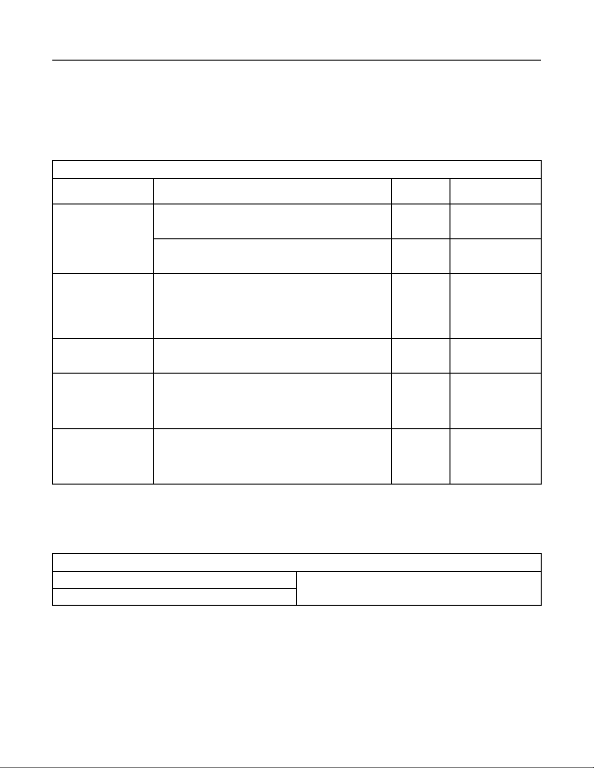
M0112246-02 85
Maintenance Section
Fluid Recommendations
Coolant Recommendations
Note: A Cat Diesel Engine equipped with air-to-air
aftercooling (ATAAC) requires a minimum of 30
percent glycol to help prevent water pump cavitation.
Table 14
Coolant Recommendations for use in Cat Diesel Engines
Recommendations Product
Cat ELC (Cat Extended Life Coolant)
Preferred
Cat ELI (Cat Extended Life Inhibitor)
Organic Additive Technology (OAT) based on a combination of a
Min requirements
Nitrite: minimum typical concentration of 500 ppm in new coolants
Acceptable Cat DEAC (Cat Diesel Engine Antifreeze/Coolant)
Min requirements for fully
formulated Heavy Duty
Commercial coolants
Min requirements for Com-
mercial coolants requiring
SCA precharge
(1)
New Coolants at 50 volume percent diluted. Coolants that are prediluted at the coolant manufacturer must be diluted with water that meets
Reagent 4 “ASTM D1193” requirements.
(2)
Maintain the in-service coolant at the given limits.
(3)
When referring to the service hours, use the interval that occurs first. These coolant change intervals are only achievable with annual S·O·S
Services Level 2 coolant sampling analysis.
Nitrite (as NO2) concentration: Minimum of 1200 ppm (70 grains/US
Silicon concentration: minimum of 100 ppm and maximum of 275
Nitrite (as NO2) concentration: Minimum of 1200 ppm (70 grains/US
Silicon concentration: minimum of 100 ppm and maximum of 275
Cat EC-1 specification and “ASTM D6210” and
monocarboxylic acid and a dicarboxylic acid
Phosphate, borate, and silicate free
Tolyltriazole: minimum typical concnetration of 900 ppm
“ASTM D6210” and
gal) and maximum of 2400 ppm (140 grains/US gal)
ppm
“ASTM D4985” and(1)
gal) and maximum of 2400 ppm (140 grains/US gal)
ppm
Service Hours
(1)(2)(3)
12000 hours or
6 years
12000 hours or
6 years
6000 hours or 6
years
3000 hours or 3
years
3000 hours or 2
years
3000 hours or 1
year
Required Maintenance
Add Cat ELC Extender at
6000 service hours or
one half of service life
Add Cat ELC Extender at
6000 service hours or
one half of service life
Add Extender at 3000
service hours or one half
of service life
SCA (Supplemental cool-
ant additive) at mainte-
nance intervals
SCA at maintenance
intervals
SCA at initial fill and SCA
at maintenance intervals
Table 15
Cat C7-C32 Marine Engines with heat exchangers
Cat diesel engines equipped with air-to-air aftercooling (ATAAC)
Special Requirements
Minimum of 30% glycol is required. 50% Glycol is recommended.
Water alone or water with SCA or with ELI is NOT allowed.
Page 86

86 M0112246-02
Maintenance Section
Fluid Recommendations
Use Only Approved SCAs and Extenders
NOTICE
Conventional coolants require the maintenance addition of SCA throughout the expected life of the coolants. Do NOT use an SCA with a coolant unless
approved specifically by the coolant supplier. The
coolant manufacturer is responsible for ensuring
compatibility and acceptable performance.
To help ensure expected performance, EC-1 coolants
require the one time maintenance addition of an extender at coolant service mid-life. Do not use an ex-
tender with a coolant unless the extender has been
approved specifically for use by the coolant manufac-
turer. The coolant manufacturer is responsible for ensuring compatibility and acceptable performance.
Failure to follow these recommendations can result in
shortened cooling system component life.
Cat ELC can be recycled into conventional coolants.
For more information, refer to Special Publication,
SEBU6251, “Cat Commercial Diesel Engine Fluids
Recommendations”.
S·O·S Services Coolant Analysis
Testing the engine coolant is important to ensure that
the engine is protected from internal cavitation and
corrosion. The analysis also tests the ability of the
coolant to protect the engine from boiling and
freezing. S·O·S coolant analysis can be done at your
Cat dealer. Cat S·O·S coolant analysis is the best
way to monitor the condition of your coolant and your
cooling system. S·O·S coolant analysis is a program
that is based on periodic samples.
Table 16
Recommended Interval
Type of
Coolant
Cat DEAC
Conventional Heavy-
Duty Coolants
Cat ELC
Cat ELI
Commercial EC-1
Coolants
(1)
The Level 2 Coolant Analysis should be performed sooner if a
problem is suspected or identified.
Note: Check the SCA (Supplemental Coolant
Additive) of the conventional coolant at every oil
change or at every 250 hours. Perform this check at
the interval that occurs first.
S·O·S Services Coolant Analysis (Level 1)
A coolant analysis (Level 1) is a test of the properties
of the coolant.
Level 1 Level 2
Every 250 hours Yearly
Optional Yearly
(1)
(1)
The following properties of the coolant are tested:
• Glycol concentration for freeze protection and boil
protection
• Ability to protect from erosion and corrosion
• pH
• Conductivity
• Visual analysis
• Odor analysis
The results are reported, and appropriate
recommendations are made.
S·O·S Services Coolant Analysis (Level 2)
A coolant analysis (Level 2) is a comprehensive
chemical evaluation of the coolant. This analysis is
also a check of the overall condition of the cooling
system.
The S·O·S coolant analysis (Level 2) has the
following features:
• Full coolant analysis (Level 1)
• Identification of metal corrosion and of
contaminants
• Identification of buildup of the impurities that
cause corrosion
• Identification of buildup of the impurities that
cause scaling
• Determination of the possibility of electrolysis
within the cooling system of the engine
The results are reported, and appropriate
recommendations are made.
For more information on S·O·S coolant analysis,
consult your Cat dealer.
Greases
If it is necessary to choose a single grease, always
choose a grease that meets or exceeds the
requirements of the most demanding application.
Remember that the products which barely meet the
minimum performance requirements can be
expected to barely produce the minimum lives of your
parts. False economy is being used if a grease is
purchased with the lowest cost as the only
consideration. Instead, use the grease that yields the
lowest total operating cost. The cost should be based
on an analysis that includes the costs of parts, labor,
downtime, and the cost of the amount of grease that
is required.
Page 87

M0112246-02 87
Maintenance Section
Fluid Recommendations
For more information, refer to Special Publication,
SEBU6251, “Cat Commercial Diesel Engine Fluids
Recommendations”.
Page 88

88 M0112246-02
Maintenance Section
Maintenance Recommendations
Maintenance
Recommendations
i08259062
General Maintenance
Information
SMCS Code: 4450; 7000
Note: Read the warnings and read the instructions
that are contained in the Safety Section of this
manual. These warnings and instructions must be
understood before you perform any operation or any
maintenance procedures.
Rotating electric machines are complex structures
that are exposed to the following forms of stress:
• mechanical
• electrical
• thermal
• environmental
• the application of electrical tests
Never perform a test over the rated potential. These
tests can damage insulation that is contaminated or
insulation that is in marginal condition. For more
information, refer to “I.E.E.E. Standard 432-1992” or
consult a Cat dealer.
i08186078
System Pressure Release
SMCS Code: 1250; 1300; 1350; 5050
Coolant System
Pressurized system: Hot coolant can cause serious burn. To open cap, stop engine, wait until radiator is cool. Then loosen cap slowly to relieve
the pressure.
To relieve the pressure from the coolant system, turn
off the engine. Allow the cooling system pressure cap
to cool. Remove the cooling system pressure cap
slowly to relieve pressure.
These stresses may be of varying magnitudes. The
electrical insulation systems are susceptible to
damage that is caused by the stresses that are listed
above. Exposure to these stresses may shorten the
effective life of the electrical insulation system.
Therefore, the service life of an electric machine will
largely depend on the serviceability of the electrical
insulation systems. An inspection program and a
testing procedure are recommended. An inspection
program and a testing procedure will ensure that the
equipment is maintained in satisfactory condition.
Maintaining the equipment will increase field
reliability.
A regular maintenance and inspection program can
provide an evaluation of the present condition of the
equipment. A regular maintenance program and a
regular inspection program can also reveal future
problems. The frequency of this maintenance
program will depend on the following factors:
• application
• environmental conditions
• experience level of the operator
• philosophy of the operator
Fuel System
To relieve the pressure from the fuel system, turn off
the engine.
High-Pressure Fuel Lines (If Equipped)
Contact with high pressure fuel may cause fluid
penetration and burn hazards. High pressure fuel
spray may cause a fire hazard. Failure to follow
these inspection, maintenance and service instructions may cause personal injury or death.
The high-pressure fuel lines are between the highpressure fuel pump and the high-pressure fuel
manifold. The high-pressure fuel lines are also
between the fuel manifold and cylinder head. These
fuel lines are different from fuel lines on other fuel
systems.
The following are the differences:
• The high-pressure fuel lines are constantly
charged with high pressure.
A regular maintenance program is recommended.
This program would involve the following steps:
• periodic disassembly
• knowledgeable visual examination of the
equipment
• The internal pressures of the high-pressure fuel
lines are higher than other types of fuel system.
Before any service or repair is performed on the
engine fuel lines, perform the following tasks:
1. Stop the engine.
Page 89
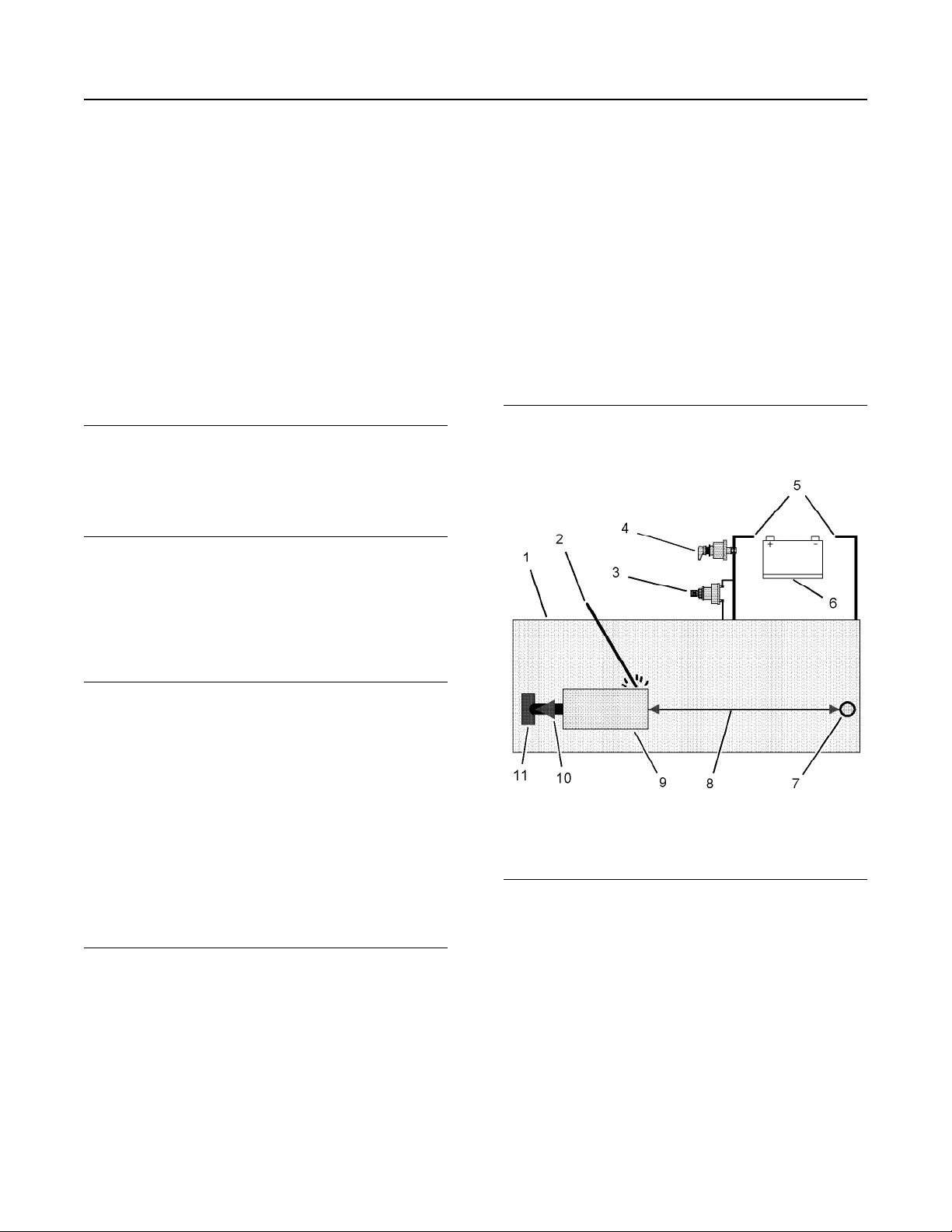
M0112246-02 89
Maintenance Section
Welding on Engines with Electronic Controls
2. Wait for 10 minutes.
Do not loosen the high-pressure fuel lines to remove
air pressure from the fuel system.
Engine Oil
To relieve pressure from the lubricating system, turn
off the engine.
i08254042
Welding on Engines with
Electronic Controls
SMCS Code: 1000
NOTICE
Because the strength of the frame may decrease,
some manufacturers do not recommend welding onto
a chassis frame or rail. Consult the OEM of the equipment or your Cat dealer regarding welding on a chassis frame or rail.
Proper welding procedures are necessary to avoid
damage to the engine ECM, sensors, and associated
components. When possible, remove the component
from the unit and then weld the component. If
removal of the component is not possible, the correct
procedure must be followed. When welding on a unit
that is equipped with a Cat Electronic Engine, the
following is considered to be the safest procedure:
3. Disconnect the J1/P1 and J2/P2 connectors from
the ECM. Move the harness to a position that will
not allow the harness to move back accidentally,
and contact any of the ECM pins.
4. Disconnect any component with a microprocessor
from the engine harness, such as:
• Engine ECM
• Product Link
• Cell/Sat Radio
• DOC Identity Modules
Do not ground the welder to electrical components
NOTICE
such as the ECM or sensors. Improper grounding
can cause damage to the drive train, the bearings,
hydraulic components, electrical components, and
other components.
Do not ground the welder across the centerline of the
package. Improper grounding could cause damage
to the bearings, the crankshaft, the rotor shaft, and
other components.
Clamp the ground cable from the welder to the component that will be welded. Place the clamp as close
as possible to the weld. This will help reduce the possibility of damage.
Note: Perform the welding in areas that are free from
explosive hazards.
1. Stop the engine. Turn the switched power to the
OFF position.
2. Disconnect the negative battery cable from the
battery. If a battery disconnect switch is provided,
open the switch.
Illustration 53 g01075639
Use the example above. The current flow from the
welder to the ground clamp of the welder will not
damage any associated components.
(1) Engine
(2) Welding electrode
(3) Keyswitch in the OFF position
(4) Battery disconnect switch in the open position
(5) Disconnected battery cables
(6) Battery
(7) Electrical/Electronic component
(8) Minimum distance between the component that is being
welded and any electrical/electronic component
(9) The component that is being welded
(10) Current path of the welder
(11) Ground clamp for the welder
Page 90

90 M0112246-02
Maintenance Section
Generator Start-up Checklist
5. Connect the welding ground cable directly to the
part that will be welded. Place the ground cable as
close as possible to the weld. This location will
reduce the possibility of welding current damage
to bearings, hydraulic components, electrical
components, and ground straps.
Note: If electrical/electronic components are used as
a ground for the welder, current flow from the welder
could severely damage the component. Current flow
from the welder could also severely damage
electrical/electronic components that are located
between the welder ground and the weld.
6. Protect the wiring harness from welding debris and
spatter.
7. Use standard welding practices to weld the
materials.
i01980600
Generator Start-up Checklist
SMCS Code: 4450
Table 17
GENERATOR START-UP CHECKLIST
RATING INFORMATION
Engine Serial Number: ___________________________________ Arrangement Number: ___________________
Generator Serial Number: _________________________________ Arrangement Number: ___________________
GENERATOR NAME PLATE INFORMATION
Voltage: ___________________ Package (prime, continuous, standby): _________________
Amperage: _________________ Kilowatts: ________________________________________
Storage Location:
Main Stator Megohmmeter Reading: Before Storage: After Storage:
Generator dried for 24 hours prior to start-up? (Y/N) Drying method:
SPACE HEATERS Yes No Comments
Space heaters operating properly?
Space heater operated 48 hours. before startup?
MEGOHMMETER TEST (SEHS9124) 30 sec.
reading
60 sec.
reading
30 sec.
corrected
60 sec.
corrected
Ambient
temp.
Comments
Beginning of
Storage
Main Stator
Main Rotor
Exciter Stator
Exciter Rotor
PMG Stator
(continued)
Page 91
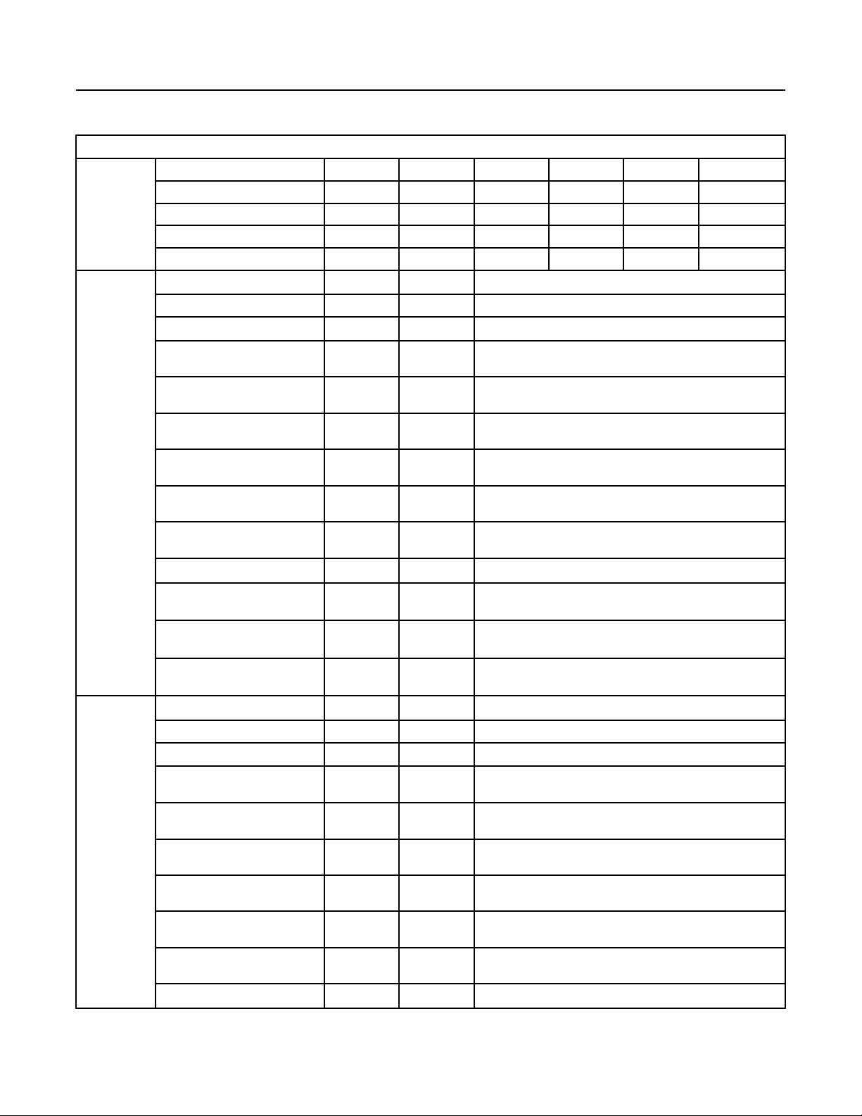
M0112246-02 91
Maintenance Section
Generator Start-up Checklist
(Table 17, contd)
GENERATOR START-UP CHECKLIST
Start-up Main Stator
Main Rotor
Exciter Stator
Exciter Rotor
PMG Stator
No Load Regulator R448 Voltage Amps Comments
E- to E+ DC
0 to 220 or 380
Self-Excited
X1 to X2
Permanent Magnet Excited
X1 to X2
Permanent Magnet Excited
X1 to Z2
Permanent Magnet Excited
X2 to Z2
AREP
X1 to X2
AREP
Z1 to Z2
Three-phase Sensing Module Voltage Amps Comments
(1)
AC
AC
AC
AC
AC
AC
AC
U
0 to 230 or 400
V
0 to 230 or 400
W
0 to 230 or 400
(1)
(1)
(1)
AC
AC
AC
Full Load Regulator R448 Voltage Amps Comments
E- to E+ AC
0 to 230 or 400
Self-Excited
(1)
AC
AC
X1 to X2
Permanent Magnet Excited
AC
X1 to X2
Permanent Magnet Excited
AC
X1 to Z2
Permanent Magnet Excited
AC
X2 to Z2
AREP
AC
X1 to X2
AREP
AC
Z1 to Z2
Three-phase Sensing Module Voltage Amps Comments
(continued)
Page 92

92 M0112246-02
Maintenance Section
Generator Start-up Checklist
(Table 17, contd)
GENERATOR START-UP CHECKLIST
U
0 to 230 or 400
(1)
V
0 to 230 or 400
(1)
W
0 to 230 or 400
(1)
This will depend on the configuration of the windings. For more information, refer to the schematic for the generator.
(1)
Table 18
GENERATOR START-UP CHECKLIST (CONT.)
ELECTRICAL Yes No Comments
Unit properly grounded
Check diodes
Over current protection
AC
AC
AC
Over voltage protection
Check for loose wiring
Adjust voltage
Adjust frequency
MECHANICAL Data Comments
Bearing temperature readings at full load Front __________ Rear ___________
Stator temperature readings at full load A0 _______ B0 _______ C0 _______
Air gap on main stator Top __________ Bottom __________
Air gap on exciter stator Top __________ Bottom __________
Air gap of PMG Top __________ Bottom __________
Ambient air to generator at full load Temperature ____________________
Supplier air opening to generator Size of Opening _________________
SWITCH GEAR/PARALLEL OPERATION
Manufacturer:
Setting 1 Setting 2 Setting 3 Comments
Circuit breaker type
Overload setting
Reverse power relay
VAR/PF Controller
Load share
INSTALLATION & LOAD INFORMATION
Neutral grounding system UPS
Enclosure type - Size
Motor: Other loads:
(continued)
Page 93
M0112246-02 93
Maintenance Section
Severe Service Application
(Table 18, contd)
- Total SKVA - Lighting
- Total HP - Computers
- Welding
- Non-linear
- Other
FULL LOAD DATA
Voltage Amps KW KVARS P.F.
i05083249
Severe Service Application
SMCS Code: 1000
An engine which operates outside of normal
conditions is operating in a severe service
application.
An engine that operates in a severe service
application may need more frequent maintenance
intervals in order to maximize the following
conditions:
• Reliability
• Service life
The number of individual applications cause the
impossibility of identifying all of the factors which may
contribute to severe service operation. Consult your
Caterpillar dealer for the unique maintenance that
may be necessary for your engine.
An application is a severe service application if any of
the following conditions apply:
Severe Environmental Factors
• Frequent operation in dirty air
• Frequent operation at an altitude which is above
1525 m (5000 ft)
• Frequent operation in ambient temperatures which
are above 32° C (90° F)
• Operation with inlet air which has a combustible
content
• Operation which is outside of the intended
application
• Operation with a plugged fuel filter
• Extended operation at low idle (more than 20% of
hours)
• Frequent cold starts at temperatures below 0° C
(32° F)
• Frequent dry starts (starting after more than 72
hours of shutdown)
• Frequent hot shutdowns (shutting down the
engine without the minimum of 2 minutes to 5
minutes of cool down time)
• Operation above the engine rated speed
• Operation below the peak torque speed
• Operating with fuel which does not meet the
standards for distillate diesel fuel as stated in
Special Publication, SEBU6251, “Caterpillar
Commercial Diesel Engine Fluids
Recommendations” “Distillate Diesel Fuel”
• Operating with fuel which contains greater than
1000 ppm (0.1%) sulfur
• Operating with a blend of distillate fuel which
contains more than 5 percent biodiesel
• Frequent operation in ambient temperatures which
are below 0° C (32° F)
Severe Operating Conditions
• Frequent operation with inlet air which has a
corrosive content
Improper Maintenance Procedures
(Maintenance Procedures Which
May Contribute to a Severe Service
Application)
• Inadequate maintenance of fuel storage tanks
from causes such as excessive water, sediment,
and microorganism growth.
Page 94

94 M0112246-02
Maintenance Section
Severe Service Application
• Extending maintenance intervals beyond the
recommended intervals
• Using fluids which are not recommended in
Special Publication, SEBU6251, “Caterpillar
Commercial Diesel Engine Fluids
Recommendations”
• Extending maintenance intervals for changing the
engine oil and engine coolant without S·O·S
validation
• Extending maintenance intervals for changing air
filters, oil filters, and fuel filters
• Failure to use a water separator
• Using filters which are not recommended by
Special Publication, PEWJ0074, “2008 Cat Filter
and Fluid Application Guide”
• Storing the engine for more than 3 months but less
than 1 yr (For information about engine storage,
refer to Special Publication, SEHS9031, “Storage
Procedure for Caterpillar Products”)
• Storing the engine for 1 yr to 2 years (For
information about engine storage, refer to Special
Instruction, REHS5001, “The Long Term Storage
and Recovery of Certain Commercial Engines”)
Page 95

M0112246-02 95
Maintenance Section
Maintenance Interval Schedule
i08289333
Maintenance Interval Schedule
SMCS Code: 1000; 4450; 7500
Ensure that all safety information, warnings, and
instructions are read and understood before any
operation or any maintenance procedures are
performed. The user is responsible for the
performance of maintenance, including all
adjustments, the use of proper lubricants, fluids, and
filters. The user is also responsible for the
replacement of components due to normal wear and
aging. Failure to adhere to proper maintenance
intervals and procedures may result in diminished
performance of the product and/or accelerated wear
of components. Use fuel consumption, service hours,
or calendar time, WHICH EVER OCCURS FIRST, to
determine the maintenance intervals. Products that
operate in severe operating conditions may require
more frequent maintenance. Before each
consecutive interval is performed, all maintenance
from the previous interval must be performed.
When Required
“ Battery - Recycle“ . . . . . . . . . . . . . . . . . . . . . . . . . 97
“ Battery or Battery Cable - Disconnect“ . . . . . . . . . 99
“ Coolant Extender (ELC) - Add“ . . . . . . . . . . . . . . 104
“ Film (Product Identification) - Clean“ . . . . . . . . . 119
“ Fuel System - Prime“. . . . . . . . . . . . . . . . . . . . . . 120
“ Generator Load - Check“. . . . . . . . . . . . . . . . . . . 128
“ Generator Set - Test“ . . . . . . . . . . . . . . . . . . . . . . 128
“ Power Factor - Check“. . . . . . . . . . . . . . . . . . . . . 136
“ Standby Generator Set Maintenance
Recommendations“ . . . . . . . . . . . . . . . . . . . . . . . . 138
“ Voltage and Frequency - Check“ . . . . . . . . . . . . 140
“ Walk-Around Inspection“ . . . . . . . . . . . . . . . . . . . 140
Every 250 Service Hours
Every 6 Months
“ Coolant Sample (Level 1) - Obtain“ . . . . . . . . . . 105
“ Generator Lead (Round Cable) - Check“ . . . . . . 127
Every Year
“ Alternator - Inspect“ . . . . . . . . . . . . . . . . . . . . . . . . 97
“ Belts - Inspect/Adjust/Replace“. . . . . . . . . . . . . . . 99
“ Coolant Sample (Level 2) - Obtain“ . . . . . . . . . . 106
“ Cooling System Supplemental Coolant Additive
(SCA) - Test/Add“. . . . . . . . . . . . . . . . . . . . . . . . . . 107
“ Crankshaft Vibration Damper - Inspect“ . . . . . . . 108
“ Engine - Clean“ . . . . . . . . . . . . . . . . . . . . . . . . . . 109
“ Engine Air Cleaner Element (Dual Element) -
Inspect/Clean/Replace“ . . . . . . . . . . . . . . . . . . . . . 110
“ Engine Crankcase Breather - Clean“ . . . . . . . . . 113
“ Engine Mounts - Inspect“ . . . . . . . . . . . . . . . . . . 115
“ Engine Oil Sample - Obtain“ . . . . . . . . . . . . . . . . 115
Every Week
“ Automatic Start/Stop - Inspect“. . . . . . . . . . . . . . . 97
“ Battery Charger - Check“ . . . . . . . . . . . . . . . . . . . 98
“ Battery Electrolyte Level - Check“ . . . . . . . . . . . . 98
“ Coolant Level - Check“ . . . . . . . . . . . . . . . . . . . . 104
“ Electrical Connections - Check“ . . . . . . . . . . . . . 109
“ Engine Air Cleaner Service Indicator -
Inspect“ . . . . . . . . . . . . . . . . . . . . . . . . . . . . . . . . . . 112
“ Engine Oil Level - Check“ . . . . . . . . . . . . . . . . . . 115
“ Fuel System Primary Filter/Water Separator -
Drain“ . . . . . . . . . . . . . . . . . . . . . . . . . . . . . . . . . . . 122
“ Generator - Inspect“. . . . . . . . . . . . . . . . . . . . . . . 125
“ Generator Bearing Temperature - Test/
Record“ . . . . . . . . . . . . . . . . . . . . . . . . . . . . . . . . . . 127
“ Jacket Water Heater - Check“ . . . . . . . . . . . . . . . 133
“ Engine Performance - Test“ . . . . . . . . . . . . . . . . 117
“ Engine Protective Devices - Check“ . . . . . . . . . . 118
“ Fuel System Primary Filter (Water Separator)
Element - Replace“ . . . . . . . . . . . . . . . . . . . . . . . . 121
“ Generator Set Vibration - Inspect“ . . . . . . . . . . . 130
“ Generator Set Vibration - Test/Record“ . . . . . . . 130
“ Hoses and Clamps - Inspect/Replace“. . . . . . . . 131
“ Radiator - Clean“ . . . . . . . . . . . . . . . . . . . . . . . . . 136
“ Rotating Rectifier - Check“ . . . . . . . . . . . . . . . . . 137
“ Starting Motor - Inspect“ . . . . . . . . . . . . . . . . . . . 139
“ Stator Lead - Check“ . . . . . . . . . . . . . . . . . . . . . . 139
“ Varistor - Check“ . . . . . . . . . . . . . . . . . . . . . . . . . 140
“ Varistor - Inspect“. . . . . . . . . . . . . . . . . . . . . . . . . 140
Page 96

96 M0112246-02
Maintenance Section
Maintenance Interval Schedule
“ Water Pump - Inspect“ . . . . . . . . . . . . . . . . . . . . . 141
Every 3 Years
“ Coolant (DEAC) - Change“ . . . . . . . . . . . . . . . . . 101
“ Coolant (ELC) - Change“. . . . . . . . . . . . . . . . . . . 103
“ Coolant Temperature Regulator - Replace“ . . . . 107
“ Turbocharger - Inspect“. . . . . . . . . . . . . . . . . . . . 139
Overhaul
“ Overhaul Considerations“ . . . . . . . . . . . . . . . . . . 133
Commissioning
“ Generator Set Alignment - Check“ . . . . . . . . . . . 129
Page 97

M0112246-02 97
Maintenance Section
Alternator - Inspect
i08259468
Alternator - Inspect
SMCS Code: 1405-040
Caterpillar recommends a scheduled inspection of
the alternator. Inspect the alternator for loose
connections and proper battery charging. Inspect the
ammeter (if equipped) during engine operation to
ensure proper battery performance and/or proper
performance of the electrical system. Make repairs,
as required.
Check the alternator and the battery charger for
proper operation. If the batteries are properly
charged, the ammeter reading should be very near
zero. All batteries should be kept charged. The
batteries should be kept warm because temperature
affects the cranking power. If the battery is too cold,
the battery will not crank the engine. The battery will
not crank the engine, even if the engine is warm.
When the engine is not run for long periods of time or
if the engine is run for short periods, the batteries
may not fully charge. A battery with a low charge will
freeze more easily than a battery with a full charge.
i08259470
Automatic Start/Stop - Inspect
SMCS Code: 4462
The generator set must be ready to operate under a
load at any time. After performing maintenance on
the generator set, inspect the position of the control
switches. Ensure the following conditions:
• The starting system is enabled.
i06738473
Battery - Replace
SMCS Code: 1401-510
Batteries give off combustible gases which can
explode. A spark can cause the combustible
gases to ignite. This can result in severe personal
injury or death.
Ensure proper ventilation for batteries that are in
an enclosure. Follow the proper procedures in order to help prevent electrical arcs and/or sparks
near batteries. Do not smoke when batteries are
serviced.
The battery cables or the batteries should not be
removed with the battery cover in place. The battery cover should be removed before any servicing is attempted.
Removing the battery cables or the batteries with
the cover in place may cause a battery explosion
resulting in personal injury.
Note: Always recycle a battery. Never discard a
battery. Return used batteries to an appropriate
recycling facility.
1. Turn the key start switch to the OFF position.
Remove the key and all electrical loads.
• The control switches are in the correct position for
automatic starting.
• The switchgear and the automatic transfer
switches that are associated with the generator
are enabled.
i08232552
Battery - Recycle
SMCS Code: 1401-510; 1401-561; 1401; 1401-005;
1401-535
Always recycle a battery. Never discard a battery.
Return used batteries to one of the following
locations:
• A battery supplier
• An authorized battery collection facility
• A recycling facility
2. Turn OFF the battery charger. Disconnect the
charger.
3. Turn battery isolator switch to OFF position.
4. The NEGATIVE “-” cable connects the NEGATIVE
“-” battery terminal to the ground plane.
Disconnect the cable from the NEGATIVE “-”
battery terminal.
5. The POSITIVE “+” cable connects the POSITIVE
“+” battery terminal to the starting motor.
Disconnect the cable from the POSITIVE “+”
battery terminal.
Note: Always recycle a battery. Never discard a
battery. Return used batteries to an appropriate
recycling facility.
6. Remove the used battery.
7. Install the new battery.
Note: Before the cables are connected, ensure that
the key start switch is OFF.
Page 98

98 M0112246-02
Maintenance Section
Battery Charger - Check
8. Connect the cable from the starting motor to the
POSITIVE “+” battery terminal.
9. Connect the cable from the ground plane to the
NEGATIVE “-” battery terminal.
i08230703
Battery Charger - Check
SMCS Code: 1401-535
Checking Before Start-Up
Check the battery charger for proper operation. If the
batteries are properly charged, the needle of the
ammeter will register near “0” (zero).
The battery charger must not produce excessive
current during start-up. Alternatively, the charger
must be automatically disconnected for start-up. If
the engine has an alternator, the charger must be
automatically disconnected during start-up and
during engine operation.
Charging the Battery
Never disconnect any charging unit circuit or battery circuit cable from the battery when the charging unit is operated. A spark can cause an
explosion from the flammable vapor mixture of
hydrogen and oxygen that is released from the
electrolyte through the battery outlets. Injury to
personnel can be the result.
Perform the following procedure to charge the
battery:
1. Ensure that the charger is turned OFF.
2. Adjust the voltage of the charger to match the
voltage of the battery.
3. Connect the POSITIVE “+” lead of the charger to
the POSITIVE “+” battery terminal. Connect the
NEGATIVE “-” lead of the charger to the
NEGATIVE “-” battery terminal.
• A strong odor of acid is present.
• The battery emits smoke or a dense vapor (gas).
Perform one of the following procedures if the battery
shows symptoms of overcharging:
• Reduce the rate of charging by a significant
amount. Complete the charging at the reduced
rate.
• Turn OFF the charger.
Table 19 describes the effects of overcharging on
different types of batteries.
Table 19
Effects of Overcharging Batteries
Type of Battery Effect
Cat General Service Batteries
Cat Premium High Output
Batteries
Cat Maintenance Free Batteries The battery may not accept a
All battery cells have a low level
of electrolyte.
When the plates of the battery
are inspected through the filler
holes, the plates may appear to
be warped. This condition can
be caused by excessive
temperature.
The battery may not pass a load
test.
charging current.
The battery may not pass a load
test.
Checking After Stopping
Ensure that the battery charger is connected
properly. Observe the meter of the charger. Record
the amperage.
i08265744
4. Turn ON the battery charger.
Overcharging of Batteries
Overcharging reduces the service life of batteries.
Use a battery charger that will not overcharge the
battery. DO NOT charge the battery if the meter of the
battery charger is in the RED zone.
Overcharging is indicated by the following symptoms:
• The battery is warm to the touch.
Battery Electrolyte Level Check
SMCS Code: 1401-535-FLV
When the engine has not run for long or short periods
of time, the batteries may not fully recharge. Ensure a
full charge to help prevent the battery from freezing.
In warmer climates, check the electrolyte level more
frequently.
Page 99

M0112246-02 99
Maintenance Section
Battery or Battery Cable - Disconnect
Ensure that the electrolyte level is 13 mm (0.5 inch)
above the top of the separators.
All lead-acid batteries contain sulfuric acid which
can burn the skin and clothing. Always wear a
face shield and protective clothing when working
on or near batteries.
1. Remove the filler caps. Maintain the electrolyte
level to the “FULL” mark on the battery.
If the addition of water is necessary, use distilled
water. If distilled water is not available, use clean
water that is low in minerals. Do not use artificially
softened water.
2. Check the condition of the electrolyte with the
245-5829 Coolant Battery Tester Refractometer.
3. Keep the batteries clean.
Clean the battery case with one of the following
cleaning solutions:
• A mixture of 0.1 kg (0.2 lb) of baking soda and
1 L (1 qt) of clean water
i06738663
Battery or Battery Cable Disconnect
SMCS Code: 1401; 1402-029
The battery cables or the batteries should not be
removed with the battery cover in place. The battery cover should be removed before any servicing is attempted.
Removing the battery cables or the batteries with
the cover in place may cause a battery explosion
resulting in personal injury.
1. Turn the start switch to the OFF position. Turn the
ignition switch (if equipped) to the OFF position
and remove the key and all electrical loads.
2. Disconnect the negative battery terminal at the
battery that goes to the start switch. Ensure that
the cable cannot contact the terminal. When four
12 volt batteries are involved, the negative side of
two batteries must be disconnected.
• A mixture of 0.1 L (0.11 qt) of ammonia and 1 L
(1 qt) of clean water
Thoroughly rinse the battery case with clean
water.
Use the 1U-9921 Battery Service Tool to clean
the battery terminals. Use a wire brush to clean
the cable clamps. Clean the items until the
surfaces are bright or shiny. DO NOT remove
material excessively. Excessive removal of
material can cause the clamps to fit improperly.
Coat the clamps and the terminals with the Loctite
®
product listed below, petroleum jelly or MPGM.
• For Americas North - Loctite LB8632
• For Europe and Africa, Middle East, CIS
(AMEC) - Loctite LB8104
• For Asia Pacific - Loctite LB8801
• For Americas South - Loctite LB Superlube
For ordering the products listed above, go to the
following address.
3. Tape the leads in order to help prevent accidental
starting.
4. Proceed with necessary system repairs. Reverse
the steps in order to reconnect all of the cables.
i02229322
Belts - Inspect/Adjust/Replace
SMCS Code: 1357-025; 1357-510; 1357-040
Inspection
Inspect the alternator belt and any accessory belts
for wear and for cracking. Replace the belts if the
belts are not in good condition.
Check the belt tension according to the information in
the Service Manual, “Specifications”.
Slippage of loose belts can reduce the efficiency of
the driven components. Vibration of loose belts can
cause unnecessary wear on the following
components:
• Belts
http://www.loctite.com/en/meta/meta-nav/
location-selector.html
• Pulleys
• Bearings
Page 100
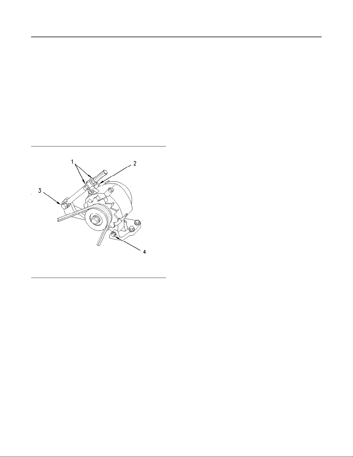
100 M0112246-02
Maintenance Section
Belts - Inspect/Adjust/Replace
If the belts are too tight, unnecessary stress is placed
on the components. This reduces the service life of
the components.
Replacement
For applications that require multiple drive belts,
replace the drive belts in matched sets. Replacing
one drive belt of a matched set will cause the new
drive belt to carry more load because the older drive
belts are stretched. The additional load on the new
drive belt could cause the new drive belt to fail.
Alternator Belt Adjustment
If new drive belts are installed, check the drive belt
tension again after 30 minutes of engine operation at
the rated rpm.
i07622832
Belts - Inspect/Adjust/Replace
SMCS Code: 1357-025; 1357-510; 1357-040
S/N: S361–Up
S/N: S371–Up
Inspect
Belt tension should be checked initially between
the first 20 to 40 hours of engine operation.
After the initial check, the belt tension should be
checked at every oil change.
To maximize the engine performance, inspect the
belts for wear and for cracking. Replace belts that are
worn or damaged.
For applications that require multiple drive belts,
replace the belts in matched sets. Replacing only one
belt of a matched set will cause the new belt to carry
more load because the older belt is stretched. The
additional load on the new belt could cause the new
belt to break.
Illustration 54 g00960176
(1) Adjusting nuts
(2) Mounting bolt
(3) Mounting bolt
(4) Mounting bolt
1. Remove the drive belt guard.
2. Loosen mounting bolts (2), (3), and (4). Loosen
adjusting nuts (1).
3. Turn adjusting nuts (1) in order to increase or
decrease the drive belt tension.
4. Tighten adjusting nuts (1). Tighten mounting bolts
(2), (3), and (4).
5. Reinstall the drive belt guard.
If the belts are too loose, vibration causes
unnecessary wear on the belts and pulleys. Loose
belts may slip enough to cause overheating.
If the belts are too tight, unnecessary stresses are
placed on the pulley bearings and on the belts.
Unnecessary stress may shorten the service life of
the components.
Remove the belt guard, if equipped. Inspect the
condition and adjustment of the alternator belts and
accessory drive belts (if equipped).
If the belt does not require replacement or
adjustment, install the belt guard. If the belt requires
adjustment or replacement, follow the procedure
below.
Replace (Serpentine Belt)
The tension on the serpentine belt may not be
adjusted.
 Loading...