

Page 1

Troubleshooting
RENR5042-02
February 2005
C11, C13,
Engines
JRE1-Up (Engine)
WJH1-Up
LGK1-Up (Engine)
GLS1-Up (Engine)
(Engine)
C15 and C18 Industrial
Page 2

i01658146
Important Safety Information
Most accidents t
basic safety rules or precautions. An accident can often be avoided by recognizing potentially hazardous
situations before an accident occurs. A person must be alert to potential hazards. This person should also
have the necess
Improper operation, lubrication, maintenance or repair of this product can be dangerous and
could result in injury or dea th.
Do not operate o
read and understood the operation, lubrication, maintenance and repair information.
Safety precautions and warnings are provided in this manual and on the product. If these hazard warnings
are not heeded
The hazards are identified by the “Safety Alert Symbol” and followed by a “Signal Word” such as
“DANGER”, “WARNING” or “CAUTION”. The Safety Alert “WARNING” label is shown below.
The meaning of this safety alert symbol is as follows:
Attention! Be
The message that appears under the warning explains the hazard and can be either written or pictorially
presented.
Operations th
this publication.
hat involve product operation, maintenance and repair are caused by failure to observe
ary training, skills and tools to perform these functions properly.
r perform any lubrication, maintenance or repair on this product, until you have
, bodily injury or death could occur to you or to other persons.
come Alert! Your Safety is Involved.
at may cause product damage are identified by “NOTICE” labels on the product and in
Caterpillar cannot anticipate every possible circumstance that might involve a potential hazard.
The warnings
procedure, work method or operating technique that is not specifically recommended by Caterpillar
is used, you must satisfy yourself that it is safe for you and for others. You should also ensure that
the product w
repair procedures that you choose.
The information, specifications, and illustrations in this publication are on the basis of information that
was availabl
measurements, adjustments, illustrations, and other items can change at any time. These changes can
affect the service that is given to the product. Obtain the complete and most current information before you
start any jo
in this publication and on the product are, therefore, not all inclusive. If a tool,
ill not be damaged or be made unsafe by the operation, lubrication, maintenance or
e at the time that the publication was written. The specifications, torques, pressures,
b. Caterpillar dealers have the most current information available.
When replacement parts are required for this
product Caterpillar recommends using Caterpillar replac
specifications including, but not limited to, physical dimensions, type, strength and material.
Failure to heed this warning can lead to premature failures, product damage, personal injury or
death.
ement parts or parts with equivalent
Page 3

RENR5042-02 3
Table of Contents
Table of Contents
Troubleshooting Section
Electronic Troubleshooting
System Overview .................................................... 5
Electronic Service Tools .......................................... 6
Electronic Display Module (If Equipped) ................. 8
Replacing the ECM ................................................. 8
Self-Diagnostics ...................................................... 9
Sensors and Electrical Connectors ....................... 10
Engine Wiring Information .................................... 13
Programming Parameters
Programming Parameters ..................................... 15
Customer Passwords ............................................ 15
Factory Passwords ............................................... 15
Factory Passwords Worksheet ............................. 16
Flash Programming .............................................. 16
Injector Trim File ................................................... 17
Service Information Report ................................... 18
System Configuration Parameters
System Configuration Parameters ........................ 20
Troubleshooting without a Diagnostic Code
Alternator (Charging Problem) .............................. 28
Battery .................................................................. 28
Can Not Reach Top Engine RPM ......................... 28
Coolant in Engine Oil ............................................ 30
Coolant Temperature Is Too High ......................... 30
ECM Will Not Accept Factory Passwords ............. 31
ECM Will Not Communicate with Other Systems or
Display Modules .................................................. 31
Electronic Service Tool Will Not Communicate with
ECM .............................................................. ...... 31
Engine Cranks but Will Not Start .......................... 32
Engine Has Early Wear ........................................ 35
Engine Misfires, Runs Rough or Is Unstable ........ 35
Engine Oil in Cooling System ............................... 36
Engine Oil Temperature Is Too High ..................... 37
Engine Stalls at Low RPM .................................... 37
Engine Vibration ................................................... 38
Engine Will Not Crank ........................................... 38
Excessive Black Smoke ........................................ 39
Excessive Engine Oil Consumption ...................... 40
Excessive Fuel Consumption ............................... 41
Excessive Valve Lash ........................................... 42
Excessive White Smoke ....................................... 42
Exhaust Temperature Is Too High ......................... 43
Fuel in Cooling System ......................................... 44
Fuel Dilution of Engine Oil .................................... 44
Intermittent Engine Shutdown ............................... 44
Intermittent Low Power or Power Cutout .............. 45
Low Engine Oil Pressure ...................................... 46
Low Power/Poor or No Response to Throttle ....... 46
Mechanical Noise (Knock) in Engine .................... 48
Noise Coming from Cylinder ................................. 49
Poor Acceleration or Response ............................ 49
Valve Rotator or Spring Lock Is Free .................... 51
Troubleshooting with a Diagnostic Code
Flash Codes .......................................................... 52
Diagnostic Codes .................................................. 52
Diagnostic Code Cross Reference ....................... 53
CID 0001 FMI 05 In
CID 0001 FMI 06 Injector Cylinder 1 short ........... 56
CID 0001 FMI 11 Injector Cylinder #1 fault ........... 57
CID 0002 FMI 05 In
CID 0002 FMI 06 Injector Cylinder 2 short ........... 57
CID 0002 FMI 11 Injector Cylinder #2 fault ........... 58
CID 0003 FMI 05 In
CID 0003 FMI 06 Injector Cylinder 3 short ........... 58
CID 0003 FMI 11 Injector Cylinder #3 fault ........... 59
CID 0004 FMI 05 Inj
CID 0004 FMI 06 Injector Cylinder 4 short ........... 59
CID 0004 FMI 11 Injector Cylinder #4 fault ........... 60
CID 0005 FMI 05 Inje
CID 0005 FMI 06 Injector Cylinder 5 short ........... 60
CID 0005 FMI 11 Injector Cylinder #5 fault ........... 61
CID 0006 FMI 05 Inje
CID 0006 FMI 06 Injector Cylinder 6 short ........... 61
CID 0006 FMI 11 Injector Cylinder #6 fault ........... 61
CID 0041 FMI 03 8 Vol
CID 0041 FMI 04 8 Volt DC Supply short to
ground ................................................................. 62
CID 0091 FMI 08 Thro
abnormal ............................................................. 62
CID 0091 FMI 13 Throttle Position calibration
required ............................................................... 63
CID 0094 FMI 03 Fuel Pressure open/short to
+batt .................................................................... 63
CID 0094 FMI 04 Fuel
CID 0100 FMI 03 Engine Oil Pressure open/short to
+batt .................................................................... 63
CID 0100 FMI 04 Engin
ground ................................................................. 64
CID 0100 FMI 10 Engine Oil Pressure Sensor
abnormal rate of ch
CID 0102 FMI 03 Boost Pressure Sensor short to
+batt .................................................................... 64
CID 0102 FMI 04 Boos
ground ................................................................. 65
CID 0102 FMI 10 Boost Pressure Sensor abnormal
rate of change ..................................................... 65
CID 0110 FMI 03 Engine Coolant Temperature
open/short to +batt .............................................. 65
CID 0110 FMI 04 Engi
to ground ............................................................. 66
CID 0111 FMI 02 Engine Coolant Level Sensor Loss
of Signal .............................................................. 66
CID 0168 FMI 00 System Voltage High ................ 66
CID 0168 FMI 01 System Voltage Low ................. 67
CID 0168 FMI 02 Syst
erratic .................................................................. 67
CID 0172 FMI 03 Intake Manifold Air Temp open/short
to +batt ................................................................ 67
CID 0172 FMI 04 Intake Manifold Air Temp short to
ground ................................................................. 68
CID 0174 FMI 03 Fuel
+batt .................................................................... 68
CID 0174 FMI 04 Fuel Temperature short to
ground ................................................................. 68
CID 0190 FMI 08 Engine Speed abnormal ........... 68
jector Cylinder 1 open circuit .. 56
jector Cylinder 2 open circuit .. 57
jector Cylinder 3 open circuit .. 58
ector Cylinder 4 open circuit .. 59
ctor Cylinder 5 open circuit .. 60
ctor Cylinder 6 open circuit .. 61
t DC Supply short to +batt .. 62
ttle Position signal
Pressure short to ground .. 63
e Oil Pressure short to
ange ..................................... 64
t Pressure Sensor short to
ne Coolant Temperature short
em Voltage intermittent/
Temperature open/short to
Page 4

4 RENR5042-02
Table of Contents
CID 0247 FMI 09 J1939 Data Link
communication
CID 0253 FMI 02 Personality Module mismatch .. 69
CID 0261 FMI 13 Engine Timing Calibration
required ............................................................... 69
CID 0262 FMI 03 5 Volt Sensor DC Power Supply
short to +batt ....................................................... 70
CID 0262 FMI 04 5
short to ground .................................................... 70
CID 0268 FMI 02 Check Programmable
Parameters ......................................................... 70
CID 0273 FMI 00 Turbo Outlet Pressure above
normal ................................................................. 71
CID 0274 FMI 03 A
to +batt ................................................................ 71
CID 0274 FMI 04 Atmospheric Pressure short to
ground ................................................................. 71
CID 0342 FMI 08 Secondary Engine Speed signal
abnormal ............................................................. 72
CID 0545 FMI 05 E
+batt .................................................................... 72
CID 0545 FMI 06 Ether Start Relay short to
ground ................................................................. 72
CID 1835 FMI 03 Auxiliary Pressure Sensor
open/short to +batt .............................................. 72
CID 1835 FMI 04
ground ................................................................. 73
CID 1836 FMI 03 Auxiliary Temperature Sensor
open/short to
CID 1836 FMI 04 Auxiliary Temperature Sensor short
to ground ............................... .............................. 73
CID 2417 FMI 05
current low .......................................................... 74
CID 2417 FMI 06 Ether Injection Control Solenoid
current high ......................................................... 7
s .................................................. 69
Volt Sensor DC Power Supply
tmospheric Pressure open/short
ther Start Relay open/short to
Auxiliary Pressure Sensor short to
+batt .............................................. 73
Ether Injection Control Solenoid
Electrical Power Supply Circuit - Test ................. 125
Engine Pressur
Test ................................................................... 129
Engine Speed/Timing Sensor Circuit - Test ........ 134
Engine Tempera
Test ................................................................... 140
Ether Injection System - Test .............................. 146
Injector Solen
Maintenance Due Lamp Circuit - Test ................. 160
PTO Switch Circuit - Test .................................... 163
Switch Circuits
Throttle Position Sensor Circuit - Test ................ 171
Warning Lamp Circuit - Test ................................ 176
Calibration Procedures
Engine Speed/Timing Sensor - Calibrate ............ 180
Throttle Positi
e Sensor Open or Short Circuit -
ture Sensor Open or Short Circuit -
oid Circuit - Test ............................ 152
- Test .......................................... 168
on Sensor - Calibrate .................... 182
Index Section
Index ................................................................... 185
4
Troubleshooting with an Event Code
Event Codes ........................................................ 75
E057 Low Engine Coolant Level Derate ............... 79
E058 Low Engine Coolant Level Shutdown .......... 79
E059 Low Engin
E096 High Fuel Pressure ...................................... 81
E360 Low Engine Oil Pressure ............................. 81
E361 High Engin
E362 Engine Overspeed ....................................... 83
E363 High Fuel Temperature ................................ 83
E443 High Auxili
E445 High Auxiliary Temperature ......................... 84
E539 High Intake Manifold Air Temperature ......... 85
Diagnostic Functional Tests
5 Volt Engine Pressure Sensor Supply Circuit -
Test ..................................................................... 87
Air Shutoff System - Test ...................................... 95
CAN Data Link Circuit - Test ............................... 100
Cat Data Link Cir
Coolant Level Sensor Circuit - Test .................... 106
Diagnostic Lamp Circuit - Test ............................. 110
Digital Sensor Su
ECM/Personality Module - Test ........................... 118
Electrical Connectors - Inspect ........................... 120
e Coolant Level Warning ............ 80
e Coolant Temperature .............. 82
ary Pressure ............................... 84
cuit - Test ................................. 104
pply Circuit - Test ..................... 114
Page 5

RENR5042-02 5
Troubleshooting Section
Troubleshooting Section
Electronic Troubleshooting
i02286178
System Overview
SMCS Code: 19
System Opera
This engine is electronically controlled. Each cylinder
has an electr
Module (ECM) sends a signal to each injector
solenoid in order to control the operation of the fuel
injection sy
Electronic Controls
The electronic system consists of the following
components: the ECM, the Mechanically Actuated
Electronic
wiring harness, the switches, and the sensors. The
ECM is the computer. The flash file is the software
for the com
maps. The operating maps define the following
characteristics of the engine:
Horsepower
•
Torque cur
•
TheECMdeterminesthetimingandtheamountof
fuel that
are based on the actual conditions and/or on the
desired conditions at any given time.
The ECM compares the desired engine speed to
the actual engine speed. The actual engine speed is
determin
The desired engine speed is determined with the
following factors:
Throttle signal
•
Other in
•
Certain diagnostic codes
•
If the desired engine speed is greater than the actual
engine speed, the ECM injects more fuel in order to
increas
ally Controlled Unit Injectors (MEUI), the
is delivered to the cylinders. These decisions
ed through the engine speed/timing sensor.
e the actual engine speed.
00
tion
onic unit injector. The Electronic Control
stem.
puter. The flash file contains the operating
ves
put signals from sensors
Fuel Injection
The ECM controls the amount of fuel that is injected
by varying the signals to the injectors. The injector will
pump fuel only
The ECM sends a high voltage signal to the solenoid.
This high voltage signal energizes the solenoid. By
controlling
voltage signal, the ECM can control injection timing
and the ECM can control the amount of fuel that is
injected.
The ECM limits engine power during cold mode
operation an
during cold mode operation. Cold mode operation
provides the following benefits:
Increased cold weather starting capability
•
Reduced war
•
Reduced white smoke
•
Cold mode is activated whenever the engine
temperature falls below a predetermined value. Cold
mode remain
rises above a predetermined value or until a time
limit is exceeded.
The flash file inside the ECM sets certain limits on
theamountoffuelthatcanbeinjected.The“FRC
Fuel Limit
control of emissions. The “FRC Fuel Limit” is a limit
that is based on the turbocharger outlet pressure.
A higher tu
thereismoreairinthecylinder.WhentheECM
senses a higher turbocharger outlet pressure, the
ECM incre
increases the “FRC Fuel Limit”, the ECM allows
more fuel into the cylinder. The “FRC Fuel Limit” is
program
Fuel Limit” cannot be changed.
The “Rat
power rating of the engine and on engine rpm. The
“Rated Fuel Limit” is similar to the rack stops and to
the torq
The “Rated Fuel Limit” provides the power curves
and the torque curves for a specific engine family and
for a sp
programmed into the ECM at the factory. The “Rated
Fuel Limit” cannot be changed.
Once the ECM determines the amount of fuel that
is required, the ECM must determine the timing
of the
center position of each cylinder from the engine
speed/timing sensor’s signal. The ECM decides when
fuel i
position and the ECM provides the signal to the
injector at the desired time. The ECM adjusts timing
for o
economy, and for optimum control of white smoke.
medintotheECMatthefactory.The“FRC
ue spring on a mechanically governed engine.
ecific engine rating. The “Rated Fuel Limit” is
fuel injection. The ECM calculates the top
njection should occur relative to the top center
ptimum engine performance, for optimum fuel
if the injector solenoid is energized.
the timing and the duration of the high
d the ECM modifies injection timing
m-up time
s active until the engine temperature
”isusedtocontroltheair/fuelratiofor
rbocharger outlet pressure indicates that
ases the “FRC Fuel Limit”. When the ECM
ed Fuel Limit” is a limit that is based on the
Page 6
6 RENR5042-02
Troubleshooting Section
Programmable P
arameters
Certain parameters that affect the engine operation
may be changed w
ith Caterpillar Electronic
Technician (ET). The parameters are stored in
the ECM, and some parameters are protected
from unauthor
ized changes by passwords. These
passwords are called factory passwords.
Passwords
Several syst
logged events are protected by factory passwords.
Factory passwords are available only to Caterpillar
dealers. Ref
Passwords” for additional information.
em configuration parameters and most
er to Troubleshooting, “Factory
i02290247
Electronic Service Tools
SMCS Code: 0
Caterpillar Electronic Service Tools are designed to
help the ser
Obtain data.
•
785
vice technician:
Table 1
Required Service Tools
Part
Number
N/A
6V-2197
7X-1171 Transducer Adapter
7X-1695
146-4080
7X-1710 Multimeter Probes
208-0059
7X-6370
167-9225
1U-5804
175-3700
4 mm Allen Wrench
Transducer
Cable As
Digital Multimeter Gp (RS232)
Adapter Cable As (70-PIN BREAKOUT)
Adapter Cable As (3-PIN BREAKOUT)
Harness (SERVICE TOOL ADAPTER)
Crimp Tool (12−AWG TO 18−AWG)
ConnectorRepairKit(DEUTSCHDT)
Description
Two short jumper wires are needed to check the
continuity of some wiring harness circuits by shorting
two adjacent terminals together in a connector. A
long extension wire may also be needed to check the
continuity of some wiring harness circuits.
Diagnose problems.
•
Read parame
•
Program parameters.
•
Calibrate sensors.
•
ters.
Required Service Tools
The tools th
order to enable a service technician to perform the
procedures.
at are listed in Table 1 are required in
Optional Service Tools
Table 2 lists the optional service tools that may help
you service the engine.
Table 2
Optional Service Tools
Part Number Description
198-4240
or
1U-5470
4C-4075
4C-4911
5P-7277
6V-9130
8T-5319
155-5176
(1)
Refer to Special Instructions, SEHS9249, “Use of 4C-4911
Battery Load Tester for 6, 8, and 12 Volt Lead Acid Batteries”
and Special Instructions, SEHS7633, “Battery Test Procedure”.
(2)
Refer to Special Instructions, SEHS 8382, “Use of the 6V-9130
Tem perature Adapter Group”.
Digital Pressure Indicator
Engine Pressure Group
Crimp Tool (4−AWG TO 10−AWG)
(1)
Battery Load Tester
Voltag e Teste r
(2)
Temperature Adapter (MULTIMETER)
Connector Tool Group
AC/DC Current Probe
Caterpillar Electronic Technician
(ET)
Cat ET can display the following information:
Page 7
RENR5042-02 7
Troubleshooting Section
Parameters
•
Event codes
•
Diagnostic cod
•
Engine configuration
•
es
Cat ET can be used by the technician to perform the
following functions:
Diagnostic tests
•
Sensor calibr
•
Flash programming
•
Set parameters
•
Table3listst
ation
he service tools that are required in
order to use Cat ET.
Table 3
Service Tools for the Use of Cat ET
Part
Number
Description
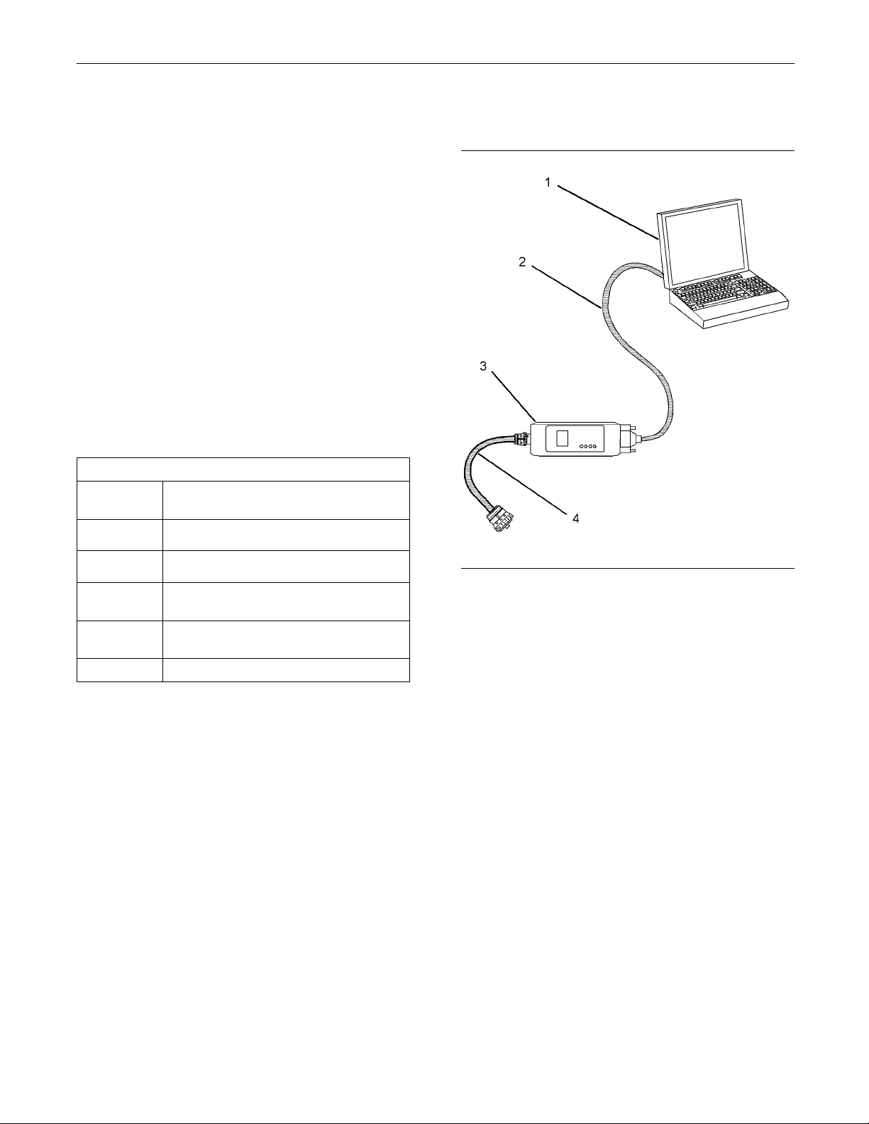
Connecting Cat ET and the
Communication
Adapter II
N/A Personal Computer (PC)
JERD2124
JERD2129
171-4400
237-7547
(1)
The 7X-1700 Communication Adapter Gp may also be used.
(2)
The 237-7547 Adapter C able As is required to connect to the
USB port on computers that are not equipped with a RS232
serial port.
Single user license for Cat ET
Data Subscription for All Engines and
Machines
Communication Adapter Gp (CAT ET TO
(1)
ECM INTERFACE) ()
(2)
Adapter Cable As
Note: For more information regarding the use of
Cat ET and the PC requirements for Cat ET, refer to
the documentation that accompanies your Cat ET
software.
Illustration 1
(1) Personal compu ter (PC)
(2) 196-0055 Adapter Cable As
(3) 1 71-4401 Comm unication Adapter As
(4) 207-6845 Adapter Cable As
g01115382
Note: Items (2), (3), and (4) are part of the 171-4400
Communication Adapter Gp.
Use the following procedure in order to connect Cat
ET and the Communication Adapter II.
1. Turn the keyswitch to the OFF position. If the
keyswitch is not in the OFF position, the engine
may start.
2. Connect cable (2) between the “COMPUTER”
end of communication adapter (3) and the RS232
serial port of PC (1).
Note: The 237-7547 Adapter Cable As is required
to connect to the USB port on computers that are not
equipped with a RS232 serial port.
3. Connect cable (4) between the “DATA LINK” end
of communication adapter (3) and the service tool
connector.
Page 8

8 RENR5042-02
Troubleshooting Section
4. PlacethekeyswitchintheONposition.If
Cat ET and the co
not communicate with the Electronic Control
Module (ECM), refer to the diagnostic procedure
Troubleshoot
Communicate With ECM”.
mmunication adapter do
ing, “Electronic Service Tool Will Not
i02139021
Electronic D isplay Module
(If Equipped)
SMCS Code: 7490
An electronic
display CID-FMI information from the electronic
control system. Refer to the service manual for your
electronic d
display module may be used to
isplay module for more information.
i02290070
Replacing the ECM
SMCS Code: 1901-510
NOTICE
Care must be taken to ensure that fluids are contained
during performance of inspection, maintenance, testing, adjusting and repair of the product. Be prepared to
collect the fluid with suitable containers before opening any compartment or disassembling any component containing fluids.
Refer to Special Publication, NENG2500, “Caterpillar
Tools and Shop Products Guide” for tools and supplies
suitable to collect and contain fluids on Caterpillar
products.
Dispose of all fluids according to local regulations and
mandates.
NOTICE
Keep all pa
Contaminants may cause rapid wear and shortened
component
rts clean from contaminants.
life.
Note: Ensure that the ECM is receiving power and
that the ECM is p
circuit before a replacement of the ECM is attempted.
Refer to Troubleshooting, “Electrical Power Supply
Circuit - Test
AtestECMcanbeusedtodetermineiftheECMis
faulty. Inst
Flash program the correct flash file into the test ECM.
Program the parameters for normal operation of the
engine. The p
in the suspect ECM. Refer to the following test steps
for details. If the test ECM resolves the problem,
connect the
returns. If the problem returns, replace the suspect
ECM.
Note: When a new ECM is not available, you may
need to remove an ECM from an engine that is not
in service.
ECM must match the interlock code for the suspect
ECM. Be sure to record the parameters from the
replaceme
Use the “Copy Configuration/ECM Replacement”
feature that is found under the “Service” menu on the
Caterpil
If the flash file and engine application are not matched,
engine da
Perform the following procedure in order to replace
the ECM:
1. Record the configuration data:
a. Connect Cat ET to the service tool connector.
b. Print the parameters from the “Configuration”
all a test ECM in place of the suspect ECM.
lar Electronic Technician (ET).
mage may result.
Refer to Troubleshooting, “Electronic Service
Too ls ”.
screen on
record all of the parameters. Record any
logged diagnostic codes and logged event
codes fo
codes from the “Calibrations” screen in the
“Service” menu on Cat ET.
roperly wired to the negative battery
”.
arameters must match the parameters
suspect ECM. Verify that the problem
The interlock code for the replacement
nt ECM on the “Parameters Worksheet”.
NOTICE
Cat ET. If a printer is unavailable,
r your records. Record the injector
The Electronic Control Module (ECM) contains no
moving parts. Replacement of the ECM can be
costly. Replacement can also be a time consuming
task. Follow the troubleshooting procedures in this
manual in order to ensure that replacing the ECM will
correct the problem. Verify that the suspect ECM is
the cause of the problem.
c. Use the “Copy Configuration/ECM
Replacement” feature that is found under the
ce” menu on Cat ET. Select “Load from
“Servi
ECM” in order to copy the configuration data
from the suspect ECM.
Note: If the “Copy Configuration” process fails and
the parameters were not obtained in Step 1.b, the
parame
parameters are stamped on the engine information
plate. Most of the parameters must be obtained from
the fa
ters must be obtained elsewhere. Some of the
ctory.
Page 9

RENR5042-02 9
Troubleshooting Section
2. Remove the ECM:
a. Turn the keyswitch to the OFF position.
b. Disconnect the
the ECM.
Use a suitable container to catch any fuel that might
spill. Clean u
Do not allow dirt to enter the fuel system. Thoroughly
clean the area around a fuel system component that
will be disconnected. Fit a suitable cover over disconnected fuel system component.
c. Remove the fuel lines (if equipped) from the
ECM.
d. Disconnect the ECM ground strap.
e. Remove the mounting bolts from the ECM.
3. Install the replacement ECM:
p any spilled fuel immediately.
P1 and P2 connectors from
NOTICE
NOTICE
c. If the “Copy Configuration” process from
Step 1.b was suc
Configuration/ECM Replacement” screen on
Cat ET and select “Program ECM”. Proceed to
Step 4.e when p
d. If the “Copy Configuration” process from Step
1.b was unsuc
ECM parameters. The parameters must match
the parameters from Step 1.b.
e. Program the engine monitoring system, if
necessary.
f. Load the injector trim files for the injectors.
Refer to Troubleshooting, “Injector Trim File”.
g. Calibrate the engine speed/timing. Refer
to Troubleshooting, “Engine Speed/Timing
Sensor - Cal
Self-Diagn
SMCS Code: 1901
cessful, return to the “Copy
rogramming is complete.
cessful, manually program the
ibrate”.
ostics
i02101273
a. Use the old mounting hardware to install the
replacement ECM.
b. Connect the fuel lines (if equipped).
Note: Verify that the fuel lines are installed correctly.
The fuel lines must not put tension on the ECM.
Rubber grommets are used to protect the ECM from
excessive vibration. The ECM should move slightly in
the rubber grommets. If the ECM cannot be moved
slightly, check that the fuel lines are not pulling the
ECM against one side of the grommets.
c. Connect the ECM ground strap.
d. Connect the P1 and P2 connectors. Tighten
the ECM connector (allen head screw) to
the proper torque. Refer to Troubleshooting,
“Electrical Connectors - Inspect” for the correct
torque value.
4. Configure the replacement ECM:
a. Flash program the flash file into the ECM.
Refer to Troubleshooting, “Flash Programming”
for the correct procedure.
b. Use Cat ET to match the engine application
and the interlock code if the replacement ECM
was used for a different application.
The Electronic Control Module (ECM) has the ability
to detect problems with the electronic system and
with engine
code is generated. An alarm may also be generated.
There are two types of codes:
Diagnostic
•
Event
•
Diagnostic Code – When a problem with the
electroni
diagnostic code. This indicates the specific problem
with the circuitry.
Diagnostic codes can have two different states:
Active
•
Logged
•
Active Code – An active diagnostic code indicates
that an active problem has been detected. Active
codes req
active codes prior to servicing logged codes.
Logged Co
the permanent memory of the ECM. The codes are
logged.
Event Code – An event code is generated by the
detection of an abnormal engine operating condition.
For exam
oil pressure is too low. In this case, the event code
indicates the symptom of a problem.
operation. When a problem is detected, a
c system is detected, the ECM generates a
uire immediate attention. Always service
de – Every generated code is stored in
ple, an event code will be generated if the
Page 10
10 RENR5042-02
Troubleshooting Section
Logged codes may not indicate that a repair is
needed. The pro
blem may have been temporary. The
problem may have been resolved since the logging
of the code. If the system is powered, it is possible
to generate an
active diagnostic code whenever a
component is disconnected. When the component is
reconnected, the code is no longer active. Logged
codes may be u
seful to help troubleshoot intermittent
problems. Logged codes can also be used to review
the performance of the engine and of the electronic
system.
Sensors and Electrical
Connectors
SMCS Code: 1900-NS; 7553-WW
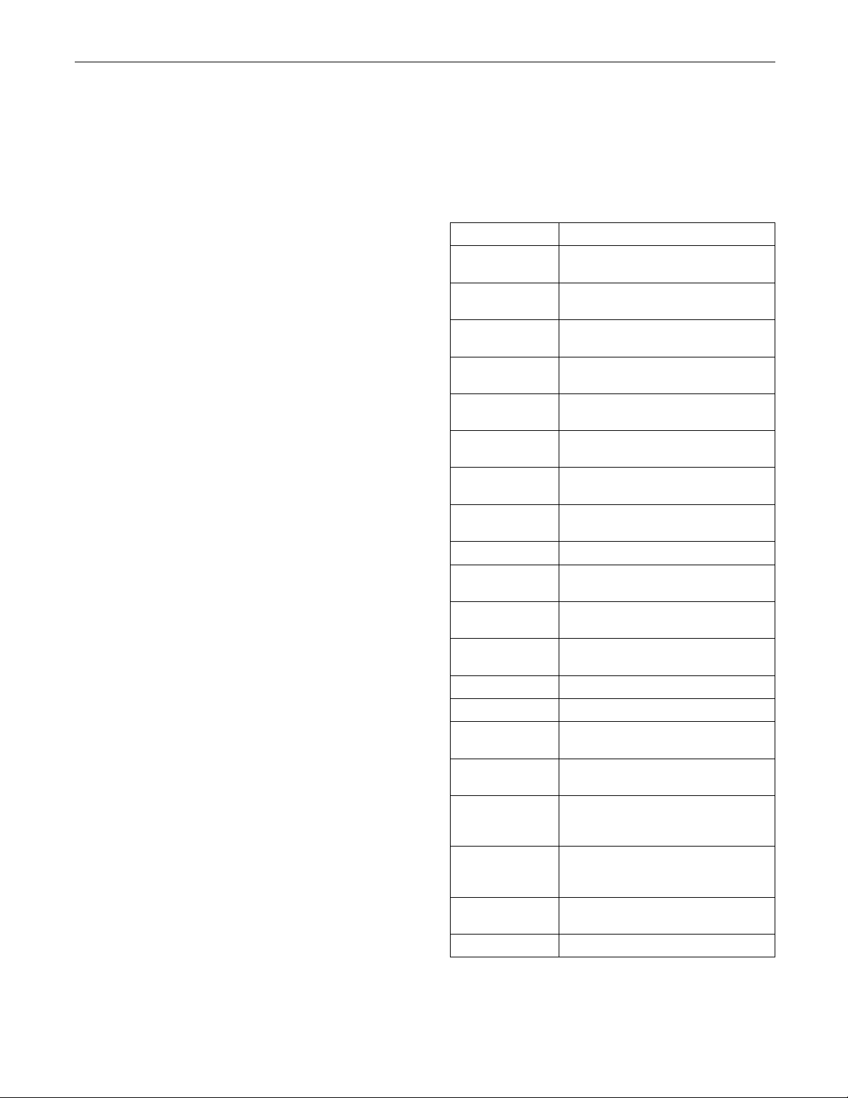
Table 4
Connector
J1/P1 ECM Connector
J2/P2 ECM Connector (“120-Pin Engine
J61/P61 Customer Connector (Optional)
J63/P63 Service Tool Connector (9-Pin
J66/P66 Customer Su
J100/P100 Coolant Temperature Sensor (2-Pin
J103/P103 Intake Manifold Air Temperature
J105/P105 Fuel Temperature Sensor (2-Pin
J142/P14
J200/P200 Boost Pressure Sensor (3-Pin
J201/P201 Engine Oil Pressure Sensor (3-Pin
J203/P203 Atmospheric Pressure Sensor (3-Pin
J209/P209 Fuel Pressure Sensor
J220/P220 Auxiliary Pressure Sensor
J300/P300 Injector Solenoid Harness (12-Pin
J400/P400 Engine Timing Calibration Probe
/P401
J401
J402/P402 Secondary Engine Speed/Timing
J403/P403 Throttle Position Sensor (3-Pin
J800/P800 Engine Coolant Level Sensor
Harness)
Harness”)
(40-Pin Connector)
Connector)
Connector (9-Pin Connector)
Connector)
Sensor (2-Pin Connector)
Connector)
2
Auxiliar
Connector)
Connector)
Connector)
Connector)
(2-Pin Connector)
ary Engine Speed/Timing
Prim
Sensor (Crankshaft) (2-Pin
Connector)
Sensor (Camshaft) (2-Pin
Connector)
Connector)
Function
(70-Pin Engine
pplied Service Tool
y Temperature Sensor
i02077683
Page 11
RENR5042-02 11
Troubleshooting Section
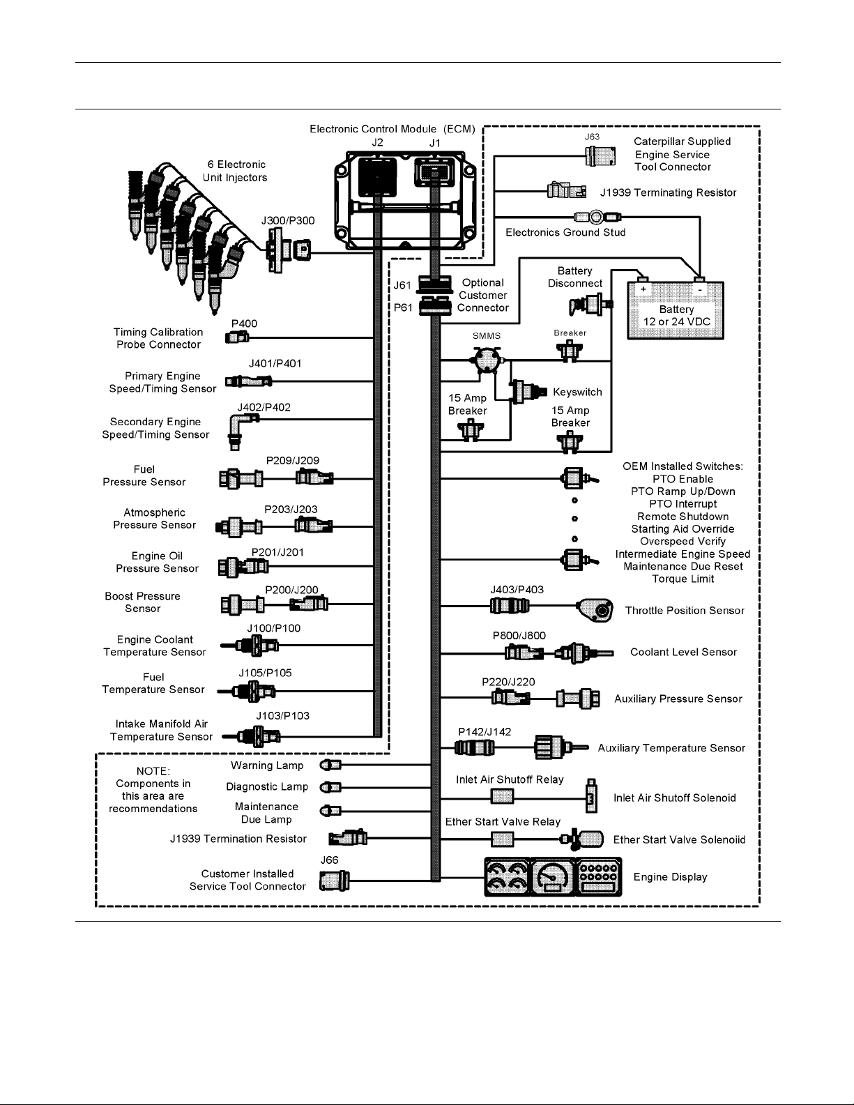
stration 2
Illu
Components for the engine’s c ontrol system
g01104142
Page 12
12 RENR5042-02
Troubleshooting Section
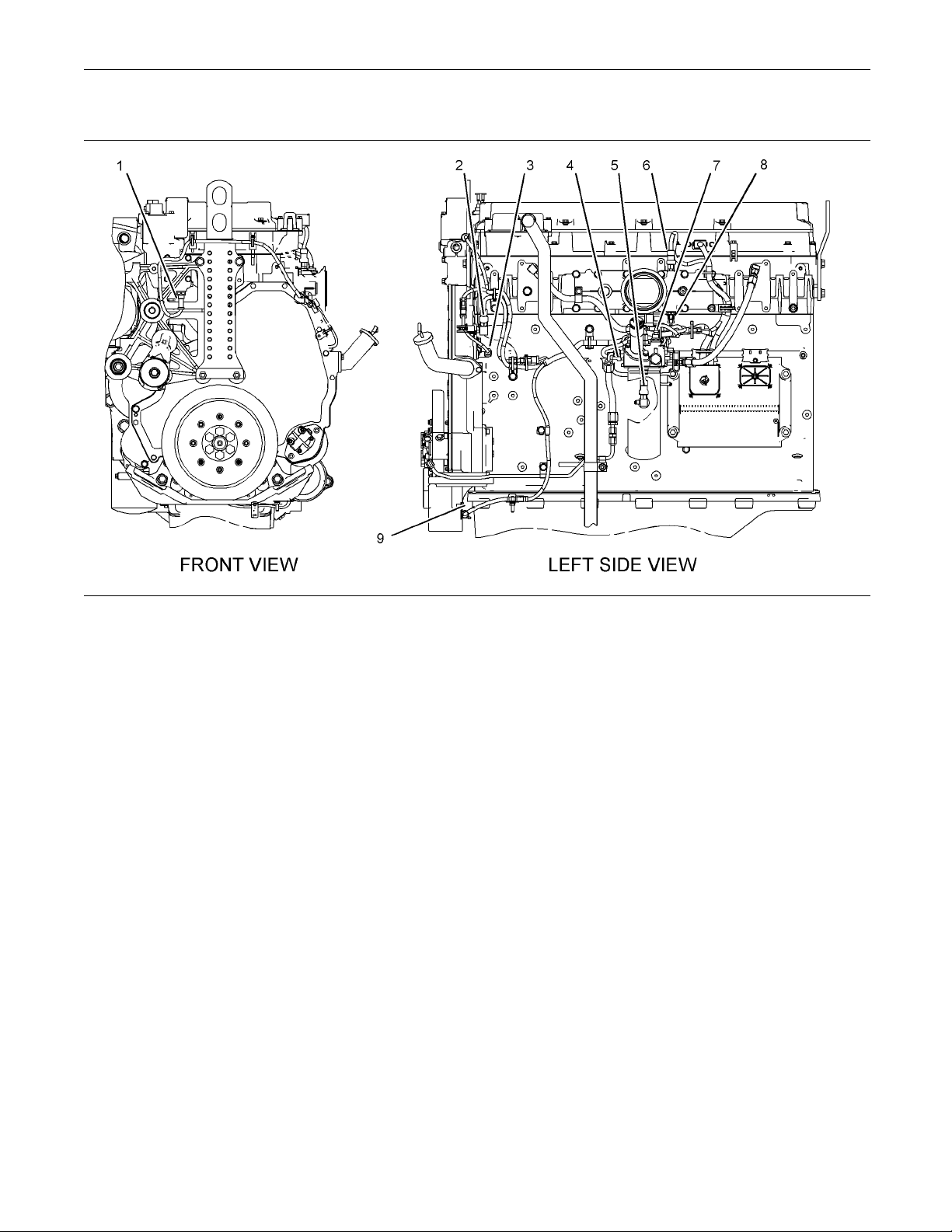
C11andC13Engines
Illustration 3
Location
(1) Coolant temperature sensor
(2) Atmospheric pressure sensor
(3) Secondary engine speed/timing sensor
s of the sensors on C11 and C13 engines
(4) Fuel pressure sensor
(5) Engine oil pressure s ensor
(6) Boost pressure sensor
g01099946
(7) Fuel temperature sensor
(8) Intake m anifold air temperature sensor
(9) Primary engine speed/timing sensor
Page 13
RENR5042-02 13
Troubleshooting Section
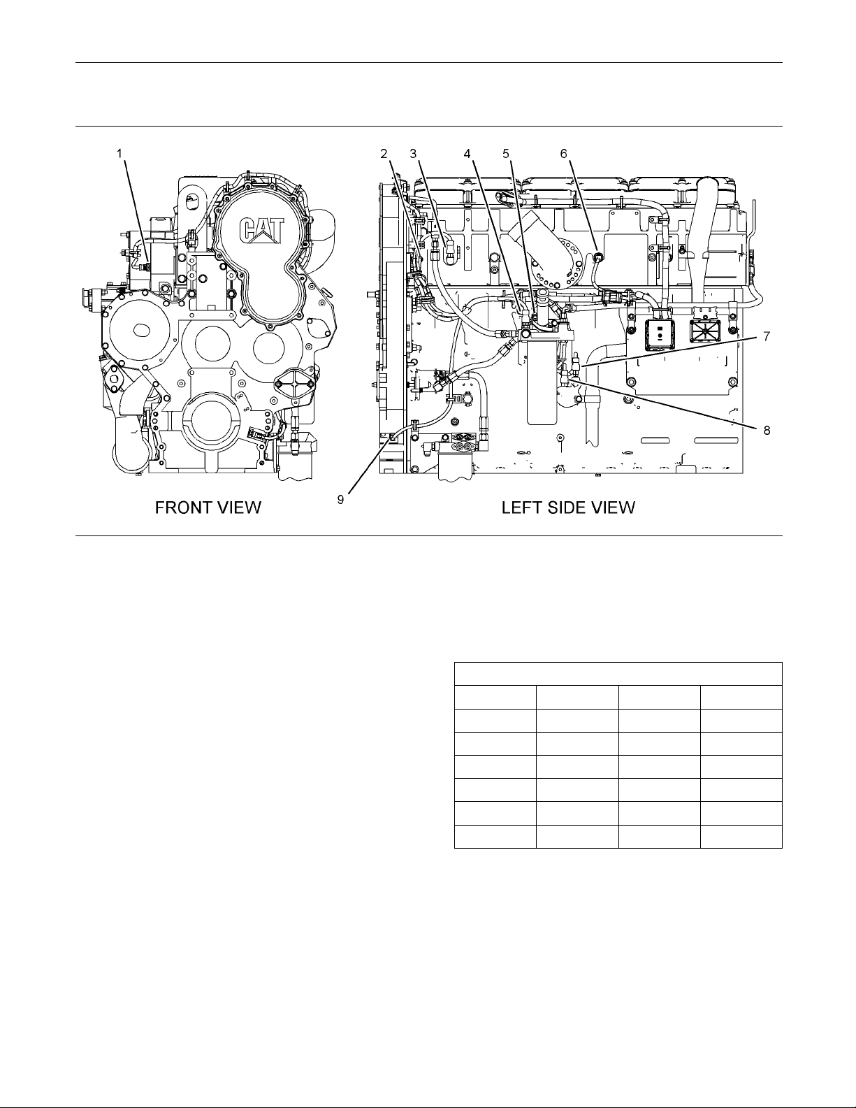
C15 and C18 Engines
Illustration 4
Location
(1) Coolant temperature sensor
(2) Secondary engine speed/timing sensor
(3) Boost pressure sensor
s of the sensors on C 15 and C1 8 engines
(4) Fuel pressure sensor
(5) Fuel temperature sensor
(6) Intake m anifold air temperature sensor
i0228538
Engine Wiring Information
SMCS Code: 1408
The wirin
The wiring schematics will change as updates are
made to the machine harness. For the most current
informa
schematic. Use the schematic with the latest revision
number.
Harness Wire Identification
Caterpillar identifies all wires with eleven solid colors.
The circuit number is stamped on the wire at a 25 mm
(1 inch
color codes.
g schematics are revised periodically.
tion, always check the revision number of the
) spacing. Table 5 lists the wire colors and the
g01099949
(7) Engine oil pressure sensor
(8) Atmospheric pressure sensor
(9) Primary engine speed/timing sensor
2
Table 5
Color Codes for the Harness Wire
Color Code Color Color Code Color
BK Black
BR Brown BU Blue
RD Red PU Purple
OR Orange GY Gray
YL Yell o w WH White
GN Green
PK Pink
For example, a wire identification of A701-GY on the
schematic would signify a gray wire with the circuit
number A701. A701-GY identifies the power circuit
for the No. 1 Injector solenoid.
Another wire identification on the schematic is the
size of the wire. The size of the wire will follow the
wire color. Wire size or gauge is referred to as AWG
(Americal Wire Gauge). AWG is a description of the
diameter of the wire.
Page 14
14 RENR5042-02
Troubleshooting Section
For example, a code of 150-OR-14 on the schematic
would indicate
thattheorangewireincircuit150isa
14 AWG wire.
If the gauge of
the wire is not listed, the wire is 16
AWG.
Conversion of
AWG Numbers to Metric
Measurements
Table6showst
used for the wires. The metric equivalent for the
diameter of each AWG number are also shown.
Table 6
Metric Equivalents for AWG Numbers
AWG
Number
20 0.8 14 1.6
18 1.0 12 2.0
16 1.3 4 3.2
he various AWG numbers that are
Diameter
(mm)
AWG
Number
Diameter
(mm)
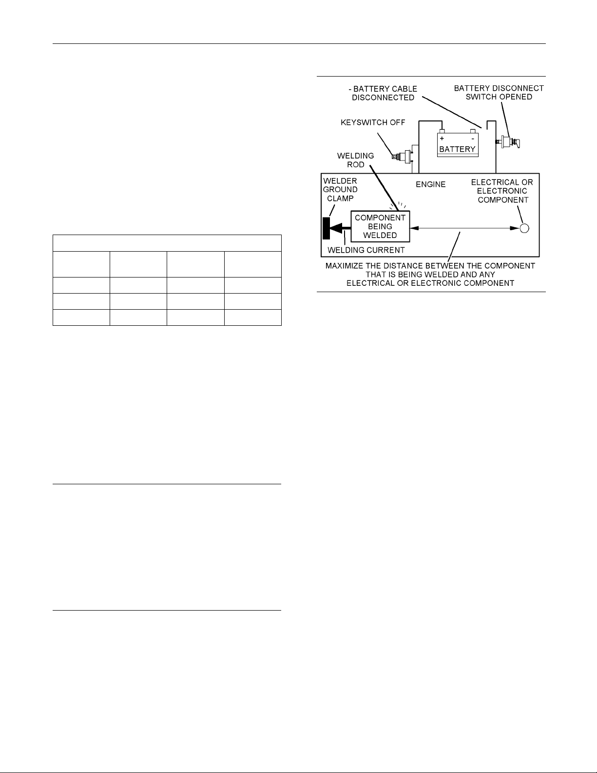
Welding on a Machine that is Equipped
ith an Electronic Control System (ECM)
w
Proper welding procedures are necessary in order
o avoid damage to the engine’s electronic control
t
module, sensors, and associated components. The
component that requires welding should be removed.
When welding on a machine that is equipped with an
ECM and removal of the component is not possible,
the following procedure must be followed. This
procedure provides the minimum amount of risk to
the electronic components.
Illustration 5
Service welding guide (typical diagram)
g01143634
3. Connect the welding ground cable as close
as possible to the area that will be welded.
Components which may be damaged by welding
include bearings, hydraulic components, and
electrical/electronic components.
4. Protect the wiring harness from welding debris
and from spatter.
5. Weld the materials by using standard welding
methods.
NOTICE
Do not ground the welder to electrical components
such as the ECM or sensors. Improper grounding can
cause damage to the drive train bearings, hydraulic
components, electrical components, and other components.
Clamp the ground cable from the welder to the component that will be welded. Place the clamp as close
as possible to the weld. This will help reduce the possibility of damage.
1. Stop the engine. Turn the keyswitch to the OFF
position.
2. Disconnect the negative battery cable from the
battery. If a battery disconnect switch is installed,
open the switch.
Page 15

RENR5042-02 15
Troubleshooting Section
Programming Pa
rameters
i02253984
Programming Parameters
SMCS Code: 1901
The Caterpillar Electronic Technician (ET) can be
used to view certain parameters that can affect the
operation of the engine. Cat ET can also be used
to change certain parameters. The parameters are
stored in the Electronic Control Module (ECM). Some
of the parameters are protected from unauthorized
changes by passwords. Parameters that can be
changed have a tattletale number. The tattletale
number shows if a parameter has been changed.
i02213792
Customer Pass words
SMCS Code: 0785
Customer pa
Alphanumeric
•
Eight characters in length
•
“Customer P
•
OR
“Customer Password #1” can be programmed and
•
“Customer Password #2” can be programmed.
sswords must meet the following criteria:
assword #1” can be programmed.
Use the following procedure in order to read customer
passwords with
1. Access the “Utilities menu”. Then access “View
Passwords” un
2. When the “Factory Password” screen appears,
record the inf
Passwords Worksheet”. Refer to Troubleshooting,
“Factory Passwords Worksheet” for additional
information
3. Obtain the factory passwords. The information
that is recor
Worksheet” must be provided. When you obtain
the factory passwords, a permanent record of your
access is gen
4. From the “Factory Password” screen, enter the
factory pas
5. When the “Read Customer Passwords” screen
appears, re
customer passwords may then be used to change
parameters that are customer programmable.
Cat ET:
der the “Utilities menu”.
ormation that is listed on the “Factory
.
ded on the “Factory Passwords
erated at Caterpillar.
swords.
cord the customer passwords. The
i02274501
Factory Passwords
SMCS Code: 0785
NOTICE
Operating the engine with a flash file not designed for
that engine will damage the engine. Be sure the flash
file is correct for your engine.
OR
No custome
•
If customer passwords have been entered, then
the custom
any parameter that is customer programmable.
Parameters that are customer programmable are
those para
limits, the power rating within an engine family
and the PTO operation. Refer to Troubleshooting,
“System C
on parameters that are customer programmable.
Use the Ca
change parameters that are customer programmable.
To obtain customer passwords, contact the owner
of the en
passwords, customer passwords may be read by
using Cat ET.
Note: Factory passwords are required in order to
read customer passwords.
r passwords are programmed.
er passwords are required to change
meters that affect the engine speed
onfiguration Parameters” for more detail
terpillar Electronic Technician (ET) to
gine. If the owner has lost the owner’s
Note: Factory passwords are provided only to
Caterpillar dealers.
Factory passwords are required to perform each of
the following functions:
Program a new Electronic Control Module (ECM).
•
When an ECM is replaced, the system
configuration parameters must be programmed
into the new ECM. A new ECM will allow these
parameters to be programmed once without factory
passwords. After the initial programming, some
parameters are protected by factory passwords.
Clear event codes.
•
Most event codes require the use of factory
passwords to clear the code once the code has
been logged. Clear these codes only when you are
certain that the problem has been corrected.
Page 16
16 RENR5042-02
Troubleshooting Section
Unlock parameters.
•
Factory passwords are required in order to unlock
certain system configuration parameters. Refer
to Troublesho
oting, “System Configuration
Parameters” for additional information.
Since factor
y passwords contain alphabetic
characters, the Caterpillar Electronic Technician (ET)
must be used to perform these functions. In order to
obtain facto
ry passwords, proceed as if you already
have the password. If factory passwords are needed,
Cat ET will request the factory passwords and
Cat ET will d
isplay the information that is required
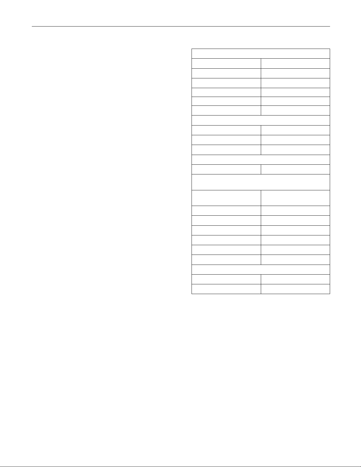
to obtain the passwords. For the worksheet that
is used for acquiring factory passwords, refer to
Troublesho
oting, “Factory Passwords Worksheet”.
i02170328
Factory Passwords Worksheet
SMCS Code: 0785
Note: A mistake in recording these parameters will
result in incorrect passwords.
Table 7
Factory Passwords Worksheet
Dealer Code
Customer’s Name
Address
Telephone Number
Information From the Engine Information Plate
Engine Serial Number
Full Load Setting
Full Torque Setting
Information From the Vehicle Odometer
Engine’s M
Information From the “Factory Password Entry
Screen” on the Caterpillar Electronic Technician (ET)
Electronic Service Tool
Serial Number
Engine Serial Number
ECM Serial Number
Total Tattletale
Reason Code
From Interlock
To I n te rl oc k
Factory Password (No. 1)
Factory Password (No. 2)
(1)
This parameter is required when the engine is being rerated.
This parameter is displayed only when the engine is being
rerated.
iles (km)
(1)
(1)
Factory Passwords
i02253997
Flash P rog ramming
SMCS Code: 1901-591
Flash Programming – This is a method of
programming or updating the flash file in an
Electronic Control Module (ECM).
The Caterpillar Electronic Technician (ET) can be
utilized to flash a new flash file into the ECM. The
flash is accomplished by transferring the data from a
PC to the ECM.
Page 17

RENR5042-02 17
Troubleshooting Section
Programming a F
1. Obtain the part number for the new flash file.
Note: If you do not have the flash file’s part number,
use the “Flash File Search” tool on the Service
Technician Wor
“Flash Software Files” feature on SIS Web.
Note: You mu s t
order to search for the flash file’s part number.
2. Connect Cat ET
3. Turn the keyswitch to the ON position. Do not start
the engine.
4. Select “WinFlash” from the “Utilities” menu on Cat
ET.
Note: If “WinFlash” will not communicate with the
ECM, refer to
Tool Will Not Communicate with ECM”.
5. Program the f
a. Select the engine ECM under the “Detected
ECMs”.
b. Press the “Browse” button in order to select
the part num
programmed into the ECM.
c. When the cor
the “Open” button.
d. Verify that
application. If the “File Values” do not match
the application, search for the correct flash file.
e. When the correct flash file is selected, press
the “Begin Flash” button.
kbench (STW). Alternatively, use the
have the engine serial number in
Troubleshooting, “Electronic Service
lash file into the ECM.
ber of the flash file that will be
the “File Values” match the
lash File
to the service tool connector.
rect flash file is selected, press
“WinFlash” Error Messages
If you receive any error messages during flash
programming, click on the “Cancel” button in order
to stop the pro
the “ECM Summary” under the “Information” menu.
Make sure that you are flashing the correct file for
your engine.
cess. Access the information about
i02289388
Injector Trim File
SMCS Code: 1290
The Caterpillar Electronic Technician (ET) is used to
load the injector trim files into the Electronic Control
Module (ECM).
The injector trim files must be loaded into the ECM if
any of the following conditions occur:
An injector is replaced.
•
The ECM is replaced.
•
A 268-02 diagnostic code is active.
•
Injectors are exchanged between cylinders.
•
Exchanging Injectors
Exchanging injectors can help determine if a
combustion problem is in the injector or in the
cylinder. If two injectors that are currently installed
in the engine are exchanged between cylinders,
the injector trim files can also be exchanged. Press
the “Exchange” button at the bottom of the “Injector
Trim Calibration” screen on Cat ET. Select the two
injectors that will be exchanged and press the “OK”
button. The tattletale for the injectors that were
exchanged will increase by one.
f. Cat ET will indicate when flash programming
has been successfully completed.
6. Start the engine and check for proper operation.
a. If a diagno
Programmable Parameters is generated,
program any parameters that were not in the
old flash
b. Access the “Configuration” screen under
the “Serv
the parameters that require programming.
Look under the “Tattletale” column. All of the
paramete
more. If a parameter has a tattletale of 0,
program that parameter.
stic code of 268-02 Check
file.
ice” menu in order to determine
rs should have a tattletale of 1 or
Note: The injector serial number and the injector
confirmation code are located on the injector.
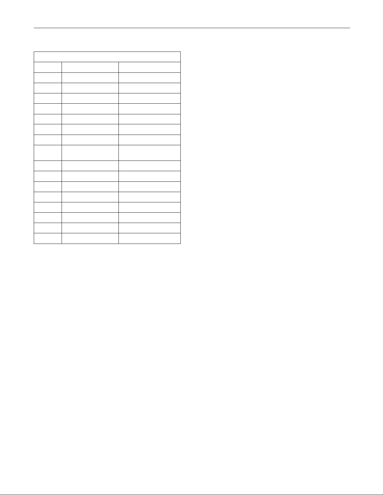
1. Refer to Table 8. Record the injector serial number
and the injector confirmation code for each
injector.
Page 18
18 RENR5042-02
Troubleshooting Section
Table 8
Information for the Injectors
Cylinder Serial Number Confirmation
1
2
3
4
5
6
7
8
9
10
11
12
13
14
15
16
2. Click on “Injector Trim Files” in SIS Web.
3. Enter the serial number for the injector in the
search field.
4. Download the injector trim file to the PC. Repeat
this procedure for each injector, as required.
5. Connect Cat ET to the service tool connector.
Refer to Troubleshooting, “Electronic Service
Too ls ”.
6. Turn the keyswitch to the ON position.
7. Select the following menu options on Cat ET:
Service
•
Calibrations
•
Injector Trim Calibration
•
Code
12. Enter the confirmation code if required by Cat ET.
13. Click on the “OK” button.
The injector tr
14. Repeat the procedure for each cylinder, as
required.
im file is loaded into the ECM.
i02278907
Service Information Report
SMCS Code: 0336
After verifyi
on the engine, it is critical to provide brief, detailed
information. This information helps Caterpillar better
serve you and
Recommendat
Customer’s Complaint
Obtain as much information from the customer
as possible. Investigate any written information
that is avai
that is gathered from the customer. The following
information is of particular importance:
Indicate if the diagnostic lamp was flashing.
•
Indicate if
•
lamp was on continuously.
Indicate t
•
present.
Be as speci
Cause of Failure
Comments on the cause of failure should include
the number of diagnostic codes that were logged.
Comments s
active code. Indicate the source of the problem. Also
indicate the method that was used to discover the
problem. E
discover the problem could be one of the following
methods:
ng the correct repair has been performed
the customer.
ions
lable and document any information
the warning lamp was flashing, or if the
he symptoms of engine operation that are
fic as possible.
hould also indicate if the code was an
xamples of the methods that were used to
8. Select the appropriate cylinder.
9. Click on the “Change” button.
10. Select the appropriate injector trim file from the
PC.
11. Click on the “Open” button.
A specific procedure in the manual was followed.
•
Avisuali
•
the engine harness existed.
nspection indicated that wire abrasion on
Page 19

RENR5042-02 19
Troubleshooting Section
An engine dynamometer test indicated that the
•
power was below
due to the loss of the no. 4 injector and an engine
dynamometer test indicated that the power was
below the spec
1700 rpm due to the loss of the no. 4 injector.
the specification at 1700 rpm
ification at all engine speeds above
Be as specifi
caspossible.
Repair Procedure
Comments on the repair procedure should include
the following types of information:
The wiring harness was repaired.
•
The Full Load
•
factory’s instructions.
Be as specifi
Setting (FLS) was changed per the
caspossible.
Page 20
20 RENR5042-02
Troubleshooting Section
System Configuration
Parameters
i02290263
System Configuration
Parameters
SMCS Code: 1901
System configuration parameters are parameters
that affect the emissions and the power of the engine.
Default values for the parameters are programmed
at the factory. Some parameters may be changed by
the customer in order to suit the needs of the specific
application.
Parameter Descriptions
“Equipment ID”
“Equipment ID” allows the customer to enter a
description into the Electronic Control Module (ECM)
in order to identify the machine. A maximum of
17 characters may be entered in the field. This
parameter is only for reference by the customer. This
parameter is not required.
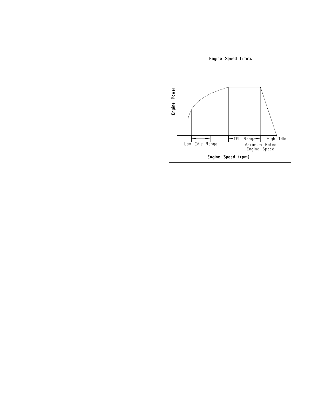
“Top Engine Limit” (TEL)
Illustration 6
“TEL” is a customer programmable parameter that
defines the maximum allowable engine speed for
maximum power. “TEL” can be programmed up to
the maximum rated engine speed. “TEL” is defined
along the engine’s lug curve.
g00763900
“Engine Serial Number”
Program the “Engine Serial Number” to match the
engine serial number that is stamped on the engine
information plate. If the ECM is replaced, the engine
serial number from the engine information plate must
be programmed into the new ECM.
Note: When you are requesting factory passwords,
always use the engine serial number that is
programmed in the ECM.
“Rating Number”
The “Rating Number” corresponds to the selected
set of performance maps for the application. This
selected set of performance maps comes out of
several unique sets of maps that are resident in the
flash file. The dealer and/or the OEM will need to
select the appropriate rating tier, if more than one
rating tier is present. The rating tiers are A through E.
Note: Factory passwords are required in order to
change the “Rating Number”.
“Engine Accel. Rate”
“Engine Accel. Rate” determines the rate of change
of the engine speed (acceleration or deceleration)
during PTO operation. This rate of change is also
used to achieve intermediate engine speed.
“Low Idle Speed”
“Low Idle Speed” is the minimum allowable operating
speed for the engine. This parameter can be
programmed between 600 and 1400 rpm.
“PTO Mode”
“PTO Mode” allows the ECM to be programmed to
either one of the two PTO configurations that are
available.
“Ramp Up/Ramp Down” – When “PTO Mode” is
programmed to “Ramp Up/Ramp Down”, the ECM
allows PTO operation with traditional features.
“Set/Resume” – When “PTO Mode” is programmed
to “Set/Resume”, the ECM allows PTO operation with
enhanced features.
Page 21
RENR5042-02 21
Troubleshooting Section
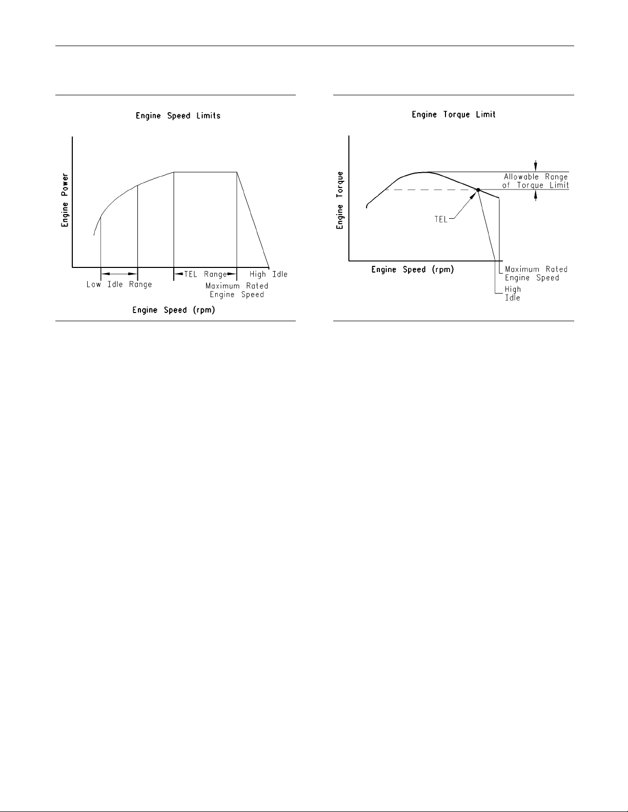
“High Idle S peed”
Illustration 7
“High Idle Speed” is the maximum no-load engine
speed when the throttle or the PTO switch is in the
maximum position.
g00763900
“Maximum Engine Torque Limit”
Illustration 8
“Engine Torque Limit” can be used to limit torque
output to the programmed value when the torque
limit switch is activated.
g00817759
Note: “High Idle Speed” cannot be programmed
lower than “TEL”.
“Intermediate Engine Speed”
“Intermediate Engine Speed” defines the speed
for the engine when the intermediate engine
speed switch is activated. This parameter can be
programmed to any engine speed between “Low Idle
Speed” and “TEL”. Engine speed will increase or
engine speed will decrease at the rate that is defined
by the programmed value for “Engine Accel. Rate”.
“Engine Power Trim”
This parameter cannot be changed.
“FLS” (Full Load Setting)
“FLS” is a number that represents the adjustment to
the fuel system that was made at the factory in order
to fine tune the fuel system. The correct value for
this parameter is stamped on the engine information
plate. Factory passwords are required in order to
change this parameter.
“FTS” (Full Torque Setting)
“FTS” is similar to “FLS”. Factory passwords are
required in order to change this parameter.
“Ether Control”
Program the “Ether Control” to “Enabled” if an
ether injection system is installed on the engine.
This allows the ECM to control ether injection. If
the engine is not equipped with ether, program this
parameter to “Disabled”.
“Air Shutoff ”
“Air Shutoff” allows the ECM to be programmed for
operation of an air shutoff system. If this parameter
is programmed to “Installed”, the ECM will activate
the air shutoff solenoid in the event of an engine
overspeed condition.
Page 22

22 RENR5042-02
Troubleshooting Section
Note: If an engine overspeed condition occurs
and “Air Shutof
switched power to the ECM must be cycled and the
air shutoff solenoid must be manually reset before
the engine wil
f” is programmed to “Enabled”, the
lrestart.
“Maintenance Indicator M ode”
The ECM records data that is related to equipment
maintenance. The ECM will activate the maintenance
indicator la
due. The maintenance indicator lamp can be reset
by actuating the maintenance clear switch. The
maintenance
hours or on fuel consumption. The ECM provides
information that pertains to maintenance intervals
and the last
mp when scheduled maintenance is
interval may be based on operating
maintenance that was performed.
“PM1 Interval”
“PM1 Interval” allows the customer to define the
maintenance interval if “Maintenance Indicator Mode”
is program
to the engine’s Operation and Maintenance Manual
for more information.
med to one of the manual options. Refer
“Aux Temp Sensor Installation Status”
Program “Aux Temp Enable” to “Installed” if an
auxiliary temperature sensor is installed. This will
allow the disp
(EMS) to monitor the temperature of another system.
Program this parameter to “Not Installed” if an
auxiliary te
lay for the Engine Monitoring System
mperature sensor is not installed.
“Throttle Position Sensor”
Program th
if a throttle position sensor is used for desired speed
control. Otherwise program this parameter to “Not
Installed
e “Throttle Position Sensor” to “Installed”
”.
“Coolant Level Sensor”
Program the “Coolant Level Sensor” to “Installed”
if a coolant level sensor is installed on the engine.
Otherwis
e program this parameter to “Not Installed”.
“Direct Fuel Control Mode”
Program the “Direct Fuel Control Mode” to “Enabled”
if an external governor is used. Once this parameter
is enable
disabled. Otherwise program this parameter to
“Disabled”.
d, the governing system in the ECM is
“Aux Press Sensor Installation Status”
Program
auxiliary pressure sensor is installed. This will allow
the display for the Engine Monitoring System (EMS)
to monit
this parameter to “Not Installed” if an auxiliary
pressure sensor is not installed.
“Aux Press Enable” to “Installed” if an
or the pressure of another system. Program
Page 23
RENR5042-02 23
Troubleshooting Section
System Configuration Parameters
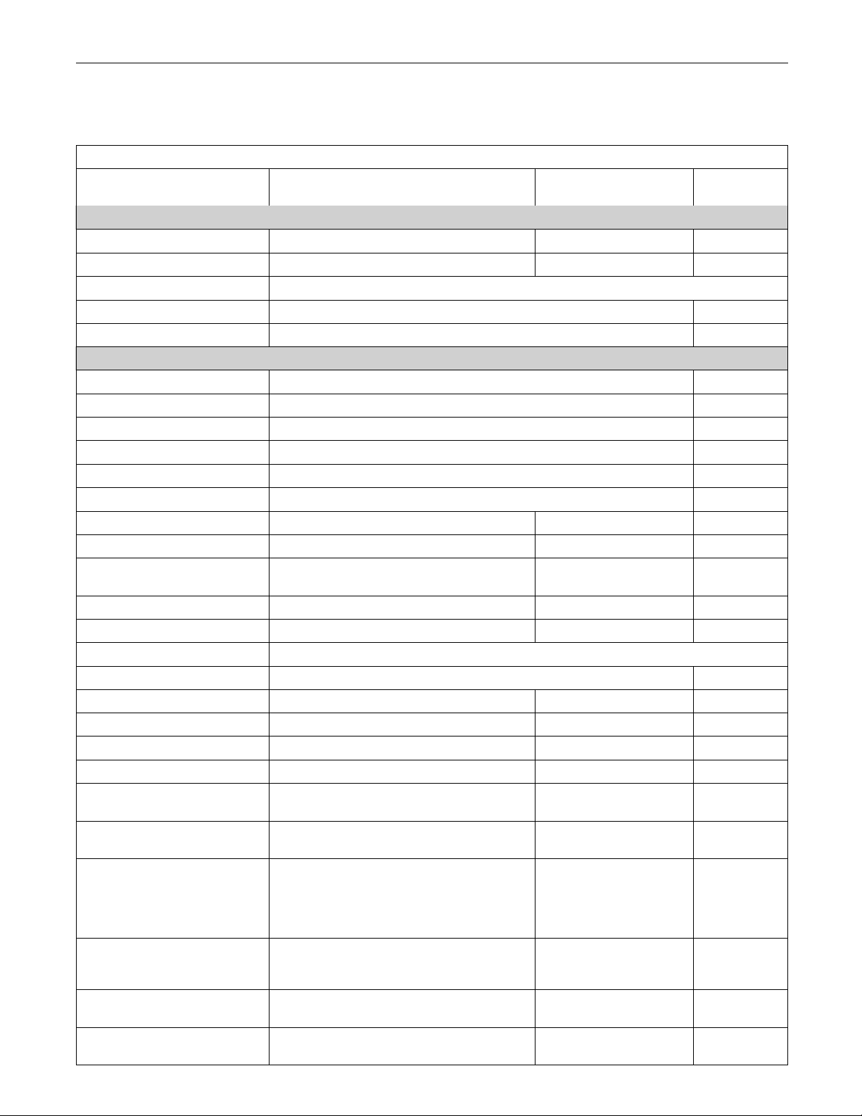
Table 9
System Configuration Parameters
Parameter Available Range or Options Default
ECM Identifi
cation Parameters
“Equipment ID” 17 alphanumeric characters “NOT PROGRAMMED” None
“Engine Serial Number” 0XX00000 or XXX00000 0XX00000 None
“ECM Serial Number” “Read Only”
(1)
“Software Gp Part Number” Software Dependent Read Only
“Software Gp Release Date” Software Dependent Read Only
Selected Engine Rating
“Rating Number” Software Dependent Customer
“Rated Power” Software Dependent Read Only
“Rated Peak Torque” Software Dependent Read Only
“Top Engine Speed Range” Software Dependent Read Only
“Test Spec” Software Dependent Read Only
“Top Eng
ine Limit”
Softwar
e Dependent
“Engine Accel. Rate” 50 to 1000 50 None
“Low Idle Speed” 600 to 1400 700 None
“PTO Mode”
dle Speed”
“High I
“Ramp Up/Ramp Down”
“Set/Resume”
“Ramp Up/Ramp Down” None
1800 to 2310 2310
“Intermediate Engine Speed” Programmed “Low Idle” to “TEL” 1100 None
“Engine Power Trim” This parameter cannot be changed.
“Maximum Engine Torque Limit” Software Dependent None
“Customer Password #1” 8 alphanumeric characters Blank Customer
“Customer Password #2” 8 alphanumeric characters Blank Customer
“FLS” (Full Load Setting) -128to127
“FTS” (Full Torque Setting) -128 to 127
her Control”
“Et
“Air Shutoff”
“No Ether”
“Continuous Flow”
“Enabled”
“Disabled”
0
0
Ether”
“No
“Disabled”
“OFF”
“Auto Fuel”
“Maintenance Indicator Mode”
“Auto Hour”
“OFF” None
“Man Fuel”
“Man Hour”
“PM1 Interval”
“Throttle Position Sensor”
“Coolant Level On”
100 to 750 Hours
or
to 28390 L (1000 to 7500 US gal)
3785
“Installed”
“Not Installed”
“Installed”
“Not Installed”
250 Hours
or
L (2500 US gal)
9463
“Not Installed” None
“Not Installed” None
Required
Password
Custome
Custom
er
Factory
Factory
None
None
None
tinued)
(con
(1)
(1)
(1)
(1)
(1)
(1)
r
Page 24
24 RENR5042-02
Troubleshooting Section
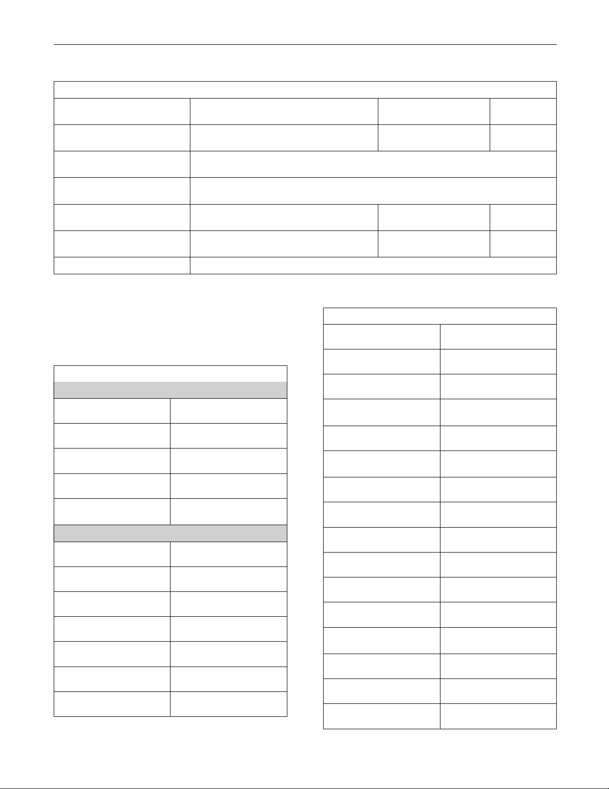
(Table 9, contd
)
System Configuration Parameters
Parameter Available Range or Options Default
“Direct Fuel Control Mode”
“Last Tool to change Customer
Parameters”
“Last Tool to c hange System
Parameters”
“Aux Temp Sensor Installation
Status”
“Aux Press Sensor Installation
Status”
“Installed”
“Not Installed”
Read Only
Read Only
“On”
“Off”
“On”
“Off”
“Total Tattletale” Read Only
(1)
The parameter can only be viewed. No changes are allowed.
Parameters Worksheet
Note: A mistake in recording this information will
result in incorrect passwords.
Table 10
(Tab le 10, contd)
“Low Idle Speed”
TO Mode”
“P
Engine Parameters
ECM Identification Parameters
“Equipment ID”
“High Idle Speed”
“Intermediate Engine
Speed”
“Engine Serial Number”
“Engine Power Trim”
Required
Password
“Not Installed” Factory
(1)
(1)
“Off” None
“Off” None
(1)
Engine Parameters
“ECM Serial Number”
“Software Gp Part Number”
“Software Gp Release
Date”
elected Engine Rating
S
“Rating Number”
“Rated Power”
“Rated Peak Torque”
“Top Engine Speed Range”
“Test Spec”
“Top Engine Limit”
“Engine Accel Rate”
(continued)
“Maximum Engine Torque
Limit”
Customer Password #1”
“
“Customer Password #2”
“FLS”
“FTS”
“Ether Control”
“Air Shutoff”
aintenance Indicator
“M
Mode”
“PM1 Interval”
“Throttle Position Sensor”
“Coolant Level Sensor”
(continued)
Page 25
RENR5042-02 25
Troubleshooting Section
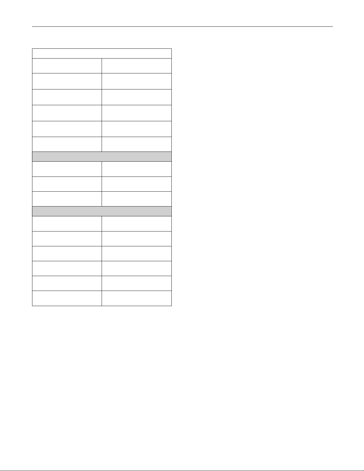
(Table 10, cont
“Direct Fuel Control Mode”
“Last Tool to change
Customer Parameters”
“Last Tool to change
System Parameters”
“Aux Press Temp
Installation Status”
“Aux Press Sensor
Installation Status”
“T otal Tattletale”
“Engine Serial Number”
“FLS”
“FTS”
d)
Engine Paramet
Information from Engine Information Plate
Injector Codes
ers
Engine speed/timing sensors
•
Inlet air temperature sensor
•
Boost pressure
•
Coolant level sensor
•
Fuel temperature sensor
•
Fuel pressure
•
Auxiliary temperature sensor
•
Auxiliary pressure sensor
•
The monitorin
sensor
sensor
g system can be locked out. In order
to change the settings, the monitoring system must
be unlocked. Access the “Parameter Lockout” under
the “Service”
menu on Cat ET in order to unlock the
monitoring system.
Warnings, de
rates, and shutdowns can be disabled
foranyparameterorforalloftheparameters.
Injector Code (1)
Injector Code (2)
Injector Code (3)
Injector Code (4)
Injector Code (5)
Injector Code (6)
Note: Compare the FLS and the FTS from the
ECM with the values that are listed on the engine
information plate. Only change the FLS and the FTS
because of a mechanical change in the engine. The
use of the wrong parameters could cause damage to
the engine. The use of the wrong parameters may
also void the Caterpillar warranty.
Monitoring System
The monitoring system determines the level of action
that is taken by the ECM in response to a condition
that can damage the engine. The monitoring of the
various sensors by the ECM can be turned “On” or
“Off”. These conditions are identified by the ECM
from the signals that are produced from the following
sensors:
Engine oil pressure sensor
•
Engine coolant temperature sensor
•
Page 26
26 RENR5042-02
Troubleshooting Section
Table 11
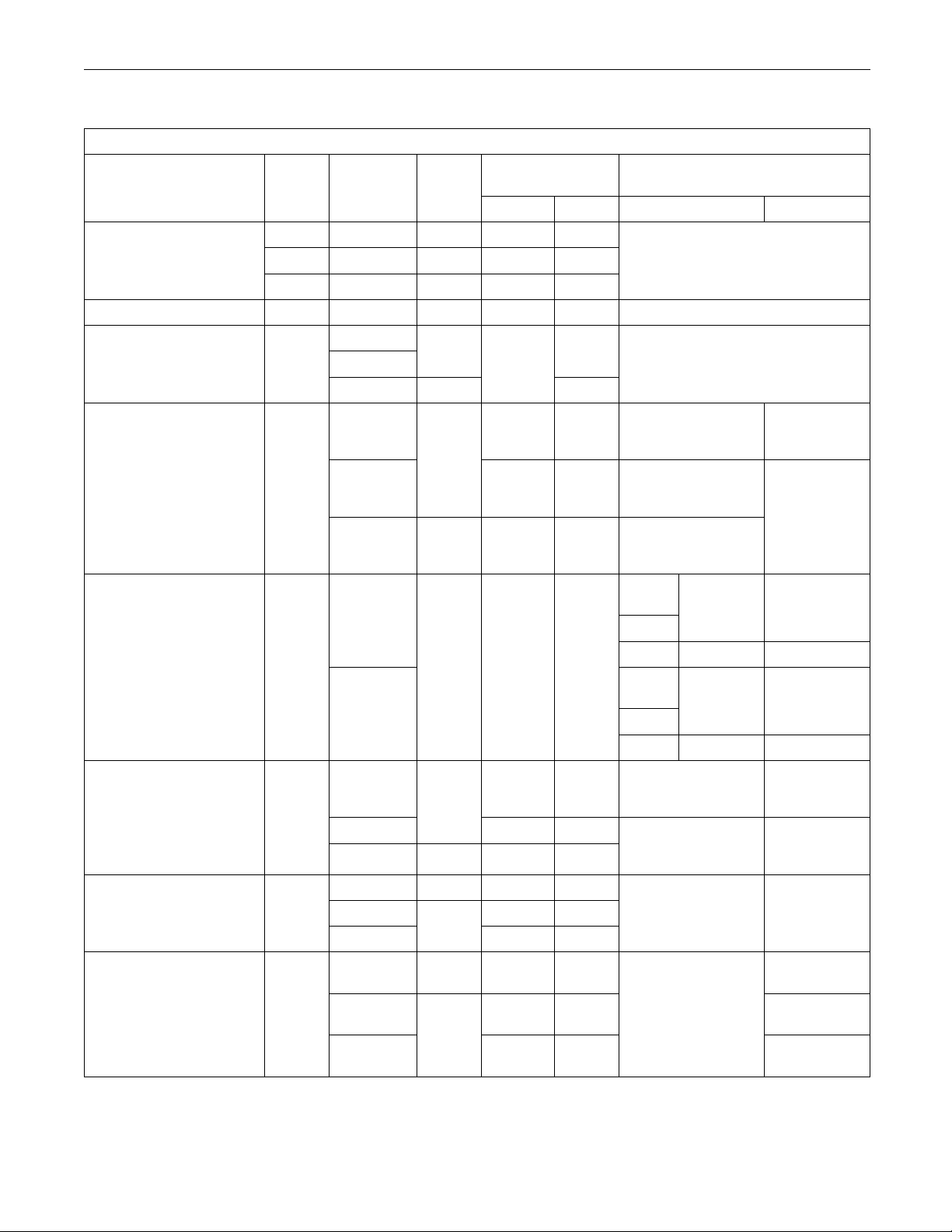
Settings for the Monitoring System
Parameter
Event
Code
E057 Derate On 1to54 10
“Low Coolant Level”
E058
E059 Warning
“High Fuel Pressure”
“Low Engine Oil Pressure”
“HighEngineCoolant
Temperature”
E096 Warning
E360
E361
“Engine Overspeed” E362
“High Fuel Temperature” E363
(2)
E443
“High Auxiliary
rature”
Te m pe
(2)
E445
Time Delay in
Action
Default
Value
Seconds
Range Default Range Default
Shutdown Off
On
On
1to54 10
1to54 10
None 8 Maps are not programmable.
Warning
On 8
Derate
Shutdown Off
None
4
Warning None 10
On
Derate
1to54 10
Shutdown Off 1to54 10
Warning
On None 1
Shutdown
Warning 1to54 30
On
Derate
Shutdown Off
1to54 10
1to54 10
Warning On 1to54 4
Derate 1to54 3“High Auxiliary Pressure”
Off
Shutdown
Warning
On
1to54 3
1to54 4
Derate 1to54 4
Off
Shutdown
1to54 4
Maps are not programmable.
85 °C (185 °F)
110°C(230°
86 °C (187 °F)
111 °C (232 °F)
87 °C (189 °F)
111 °C (232 °F)
C11/
C13
C15
C18
C11/
C13
C15
C18
70 °C (158 °F)
90 °C (194 °F)
71 °C (160 °F)
91 °C (196 °F)
0kPa(0psi)
3150 kPa (457 psi)
0°C(0
140 °C (284 °F)
Set Points
None
to
F)
110 °C
(230 °F)
to
111 °C
(232 °F)
to
1800-2600 2600
1800-2500 2500
1800-2800 2800
1800-2700 2700
to
to
to
90 °C (194 °F)
91 °C (196 °F)
1500 kPa
(218 psi)
105 °C
(221 °F)
°F)
to
106 °C
(223 °
107 °C
(224 °F)
(continued)
(1)
(1)
F)
Page 27

RENR5042-02 27
Troubleshooting Section
(Table 11, cont
d)
Settings for the Monitoring System
Parameter
“High Engine Air Inlet
Temperature”
(1)
The maps may b e different. The maps d epend on the model of the engine.
(2)
The engine must be equipped with the appropriate sensor.
Event
Code
E539
Action
Warning None 8
Derate
Default
Value
On
Time Delay in
Seconds
Range
Default
1to54 8
Range
None
Set Points
Default
75 °C (167 °F)
79 °C (174 °F)
Page 28

28 RENR5042-02
Troubleshooting Section
Troubleshooti
ng without a
Diagnostic Code
Alternator
(Charging Problem)
SMCS Code: 1405-035
Probable Causes
Alternator drive belts
•
Charging circuit
•
Regulator
•
Alternator
•
Recommended Actions
Alternator Drive Belts
i02119218
Probable Causes
Battery
•
An electrical device drains the battery.
•
Recommended Actions
Battery
1. Verify that the battery is no longer able to hold a
charge.
2. Replace the battery.
Electrical Device
1. Verify that an electrical device drained the battery
by being left in the ON position.
2. Charge the battery.
3. Verify that the battery is able to maintain a charge.
i02290338
1. Inspect the condition of the alternator drive belts.
If the alternator drive belts are worn or damaged,
replace the belts.
2. Check the tension on the alternator drive belts.
Adjust the tension, if necessary.
Charging Circuit
Inspect the battery cables, wiring, and connections in
the charging circuit. Clean all connections and tighten
all connections. Replace any faulty parts.
Alternator or Regulator
Verify that the alternator or the regulator is operating
correctly. Refer to Special Instruction, REHS0354,
“Charging System Troubleshooting” for the proper
testing procedures. Repair the alternator or replace
the alternator, as needed.
i02170483
Battery
SMCS Code: 1401-035
Can Not Reach Top Engine
RPM
SMCS Code: 1915-035
Note: If this
Troubleshooting, “Low Power/Poor or No Response
to Throttle”.
The connection of any electrical equipment and
the discon
cause an explosion hazard which may result in injury or death. Do not connect any electrical equipment or dis
explosive atmosphere.
Probable Causes
Diagnosti
•
Event codes
•
Programmable parameters
•
problem occurs only under load, refer to
nection of any electrical equipment may
connect any electrical equipment in an
c codes
Note: This is not an electronic system problem.
Refer to Special Instruction, REHS0354, “Charging
System Troubleshooting” for the proper testing
procedures.
Cold mode
•
Altitude derate
•
Throttle signal
•
Page 29

RENR5042-02 29
Troubleshooting Section
Rated fuel position and/or FRC fuel position
•
Boost pressure sensor
•
Fuel supply
•
Air inlet and exhaust system
•
Accessory equipment
•
Recommended Actions
Diagnostic Co
Certain diagnostic codes and/or event codes may
cause poor per
Electronic Technician (ET) and check for active codes
and logged codes. Troubleshoot any codes that are
present befor
Programmable Parameters
Check the following parameters on Cat ET:
“Throttle Po
•
“Desired Speed Input Configuration”
•
“Direct Fuel Control Mode”
•
Determine th
application. Program the parameters to match the
type of throttle that is used. Refer to Troubleshooting,
“Throttle Po
information.
Note: The en
parameters are not programmed correctly.
des and Event Codes
formance. Connect the Caterpillar
econtinuingwiththisprocedure.
sition Sensor”
etypeofthrottlethatisusedinthe
sition Sensor Circuit - Test” for more
gine will have poor performance if the
Throttle Signal
Connect Cat ET to the service tool connector. View
the status for the throttle position on the status
screen. Opera
position to the High Idle position. The status should
be 0 percent at low idle and the status should be 100
percent at hi
in the full range, refer to Troubleshooting, “Throttle
Position Sensor - Calibrate”.
Diagnostic codes that are related to the J1939 data
link will prevent correct operation of the throttle if the
throttle pos
there is a problem with the data link, the engine will
remain at low idle until the data link is repaired.
te the throttle from the Low Idle
gh idle. If the status can not operate
ition is transmitted over the data link. If
Boost Pressure Sensor, Rated Fuel
Position and/or FRC Fuel Position
1. With the engine at full load, monitor “Fuel Position”
and “Rated Fuel Limit” on the status screen. If
“Fuel Posi
then check air inlet manifold pressure.
2. Verify tha
that are associated with the boost pressure sensor
or with the atmospheric pressure sensor.
3. Monitor boost pressure and atmospheric pressure
on the status screen for normal operation.
Note: Atmospheric pressure is not a default
parameter on a status screen. You must manually
select th
order to monitor the atmospheric pressure sensor.
Fuel Supp
tion” does not equal “Rated Fuel Limit”
t there are no active diagnostic codes
e parameter for the atmospheric pressure in
ly
Cold Mode
Use the electronic service tool to verify that the
engine has e
appear if the engine is operating in cold mode. This
may limit engine speed.
xited cold mode. A status flag will
Altitude Derate
The engine
Connect Cat ET to the service tool connector. Check
for an active engine derate on the status screens.
Note: There are no event codes that are associated
with the altitude derate.
may be derated due to high elevation.
1. Check the fuel lines for the following problems:
restrict
problems are found with the fuel lines, repair the
lines and/or replace the lines.
2. Check the fuel tank for foreign objects which may
block the fuel supply.
3. Check for air in the low pressure fuel supply
system if any of the following procedures have
been per
•
•
•
4. Purge air from the low pressure fuel supply circuit.
Refer to
“Fuel System - Prime” for the correct procedure.
ions, collapsed lines, and pinched lines. If
formed:
Replacement of the fuel filters
Service o n the low pressure fuel supply circuit
Replace
ment of unit injectors
Operation and Maintenance Manual,
Page 30

30 RENR5042-02
Troubleshooting Section
Note: A sight glass in the low pressure supply line is
helpful in diag
5. Cold weather adversely affects the characteristics
of the fuel. Re
Maintenance Manual for information on improving
the characteristics of the fuel during cold weather
operation.
6. Check the fuel pressure during engine cranking.
Check the fue
the fuel filter. Refer to Specifications for correct
pressure values. If the fuel pressure is low,
replace the f
low, check the following items: fuel transfer pump,
fuel transfer pump coupling, and fuel pressure
regulating
nosing air in the fuel.
fer to the Operation and
l pressure on the outlet side of
uel filters. If the fuel pressure is still
valve.
Air Inlet and Exhaust System
1. Clean plugged air filters or replace plugged air
filters. Refer to the Operation and Maintenance
Manual.
2. Check the air inlet and exhaust system for
restricti
Adjusting, “Air Inlet and Exhaust System”.
Accessory
Check all accessory equipment for problems that
may create
any damaged components or replace any damaged
components.
ons and/or leaks. Refer to Testing and
Equipment
excessive load on the engine. Repair
i02119298
Recommended Ac
tions
Engine Oil Cooler Core
1. Check for leaks in the oil cooler core. If a leak is
found, install a new oil cooler core. Refer to the
Disassembly a
2. Drain the crankcase and refill the crankcase with
clean engine o
Refer to the Operation and Maintenance Manual.
Cylinder Head
1. Remove the cylinder head. Refer to the
Disassembly
2. Check the cylinder liner projection. Refer to the
Te s ti ng a n d A
3. Install a new cylinder head gasket and new water
seals in the s
and Assembly manual.
Cylinder He
Check for cracks in the cylinder head. If a crack
is found, re
the cylinder head. Refer to the Disassembly and
Assembly manual.
nd Assembly manual.
il. Install new engine oil filters.
Gasket
and Assembly manual.
djusting manual.
pacer plate. Refer to the Disassembly
ad
pair the cylinder head and/or replace
Cylinder Liner
Check for cr
cracked cylinder liners. Refer to the Disassembly and
Assembly manual.
acked cylinder liners. Replace any
Coolant in Engine Oil
SMCS Code
Probable
Engine oil cooler core
•
Cylinder head gasket
•
Cylinder
•
Cylinder liner
•
Cylinder block
•
: 1348-035; 1395-035
Causes
head
Cylinder Block
Inspect th
found, repair the cylinder block or replace the cylinder
block.
e cylinder block for cracks. If a crack is
i02194394
Coolant Temperature Is Too
High
SMCS Code: 1395-035
Refer to Systems Operation/Testing and Adjusting,
“Cooling System - Check” for information on
determin
ing the cause of this condition.
Page 31

RENR5042-02 31
Troubleshooting Section
i02285862
ECM Will N ot Accept Factory
Passwords
SMCS Code: 1901-035
Probable Causes
One of the foll
correctly on the Caterpillar Electronic Technician
(ET):
Passwords
•
Serial number
•
Total tattletale
•
Reason code
•
Recommended Actions
1. Verify that t
Check every character in each password. Remove
the electrical power from the engine for 30
seconds and t
owing items may not be recorded
s
he correct passwords were entered.
hen retry.
Electronic Control Module (ECM)
•
Recommended Actions
1. Connect the electronic service tool to the
service tool connector. If the ECM does not
communicate w
to Troubleshooting, “Electronic Service Tool Will
Not Communicate with ECM”.
2. Troubleshoot the Cat Data Link for possible
problems. Refer to Troubleshooting, “Cat Data
Link Circuit
3. Troubleshoot the CAN data link (if equipped) for
possible pro
“CAN Data Link Circuit - Test”.
ith the electronic service tool, refer
-Test”.
blems. Refer to Troubleshooting,
i02254038
Electronic Service Tool Will
Not Communicate with ECM
SMCS Code: 0785-035; 1901-035
Probable Causes
2. Verify that the Cat ET is on the “Factory Password”
screen.
3. Use Cat ET to verify that the following information
has been ente
Engine serial number
•
Serial number for the electronic control module
•
Serial numb
•
Total tattletale
•
Reason code
•
red correctly:
er for Cat ET
i02279167
ECM Will No t Communicate
with Other S yste ms or Display
Modules
SMCS Code: 1901-035
Probable Causes
Configurat
•
Electrical connectors
•
Communication adapter and/or cables
•
Electrical
•
connector
Caterpilla
•
hardware
Electrical
•
Module (ECM)
Flash file
•
Cat Data Link
•
ion for the communications adapter
power supply to the service tool
r Electronic Technician (ET) and related
power supply to the Electronic Control
Recommended Actions
Start the engine. If the engine starts, but the ECM
will not communicate with Cat ET, continue with
this proce
Troubleshooting, “Engine Cranks but Will Not Start”.
If the engine will not crank, refer to Troubleshooting,
“Engine W
dure. If the engine will not start, refer to
ill Not Crank”.
Wiring and/or electrical connectors
•
Cat Data Li
•
CAN data link (if equipped)
•
nk
Configuration for the Communications
Adapter
1. Access “Preferences” under the “Utilities” menu
on Cat ET.
Page 32

32 RENR5042-02
Troubleshooting Section
2. Verify that the correct “Communications Interface
Device” is sele
3. Verify that the correct port is selected for use by
the communica
Note: The most commonly used port is “COM 1”.
4. Check for any hardware that is utilizing the
same port as the communications adapter. If any
devices are co
or close the software programs for that device.
Electrical C
Check for correct installation of the J1/P1 and J2/P2
ECM connecto
Refer to Troubleshooting, “Electrical Connectors Inspect”.
cted.
tion adapter.
nfigured to use the same port, exit
onnectors
rs and of the service tool connector.
Communication Adapter and/or Cables
1. If you are us
ensure that the firmware and driver files for the
communication adapter are the most current files
that are ava
do not match, the communication adapter will not
communicate with Cat ET.
ing a “Communication Adapter II”,
ilable. If the firmware and driver files
Electrical Power Supply to the Electronic
Control Module
Check power to the ECM. Refer to Troubleshooting,
“Electrical P
Note: If the ECM is not rec eiving battery voltage, the
ECM will not co
ower Supply Circuit - Test”.
(ECM)
mmunicate.
Flash File
Ensure that the correct flash file is properly installed
in the ECM.
Note: The new ECM does not have a flash file.
The engine will not start and the engine will not
communicate
been installed. Refer to Troubleshooting, “Flash
Programming”.
with Cat ET until the flash file has
Cat Data Link
Troublesho
Refer to Troubleshooting, “Cat Data Link Circuit Tes t” .
ot the Cat Data Link for possible problems.
i02290294
2. Disconnect the communication adapter and the
cables from the service tool connector. Reconnect
the commun
connector.
3. Verify tha
the communication adapter and the service tool
connector. Refer to Troubleshooting, “Electronic
Service T
ication adapter to the service tool
t the correct cable is being used between
ools”.
Electrical Power Supply to the Service
Tool Conn
Verify that battery voltage is present between
terminal
communication adapter is not receiving power, the
display on the communication adapter will be blank.
ector
s A and B of the service tool connector. If the
Cat ET and Related Hardware
In order
as the problem, connect Cat ET to a different engine.
If the same problem occurs on a different engine,
check Ca
determine the cause of the problem.
to eliminate Cat ET and the related hardware
t ET and the related hardware in order to
Engine Cranks but Will Not
Start
SMCS Code: 1000-035
Probable Causes
Electrical power to the Electronic Control Module
•
(ECM)
Flash file
•
Remote shu
•
Air shutoff circuit
•
Starting motor solenoid or starting circuit
•
Engine spe
•
Electrical connections to the electronic unit injector
•
Fuel supply
•
Combustio
•
tdown switch
ed/timing sensors
n problem
Page 33

RENR5042-02 33
Troubleshooting Section
Recommended Ac
tions
Electrical Power to the ECM
1. Turn the keyswitch OFF.
2. Check the posit
connections to the ECM.
3. Perform a pull
negative battery wires.
4. Check the nega
engine ground.
5. Turn the keysw
6. The warning lamps should illuminate for five
seconds.
If the warning lamp illuminates for five seconds,
continue wit
If the warning lamp does not illuminate for five
seconds, ref
Supply Circuit - Test”.
ive battery and negative battery
test on positive battery wires and
tive battery connection to the
itch ON.
h this procedure.
er to Troubleshooting, “Electrical Power
Starting Motor Solenoid or Starting
Circuit
1. Test the operation of the starting motor solenoid.
2. Check the engine wiring to the starting motor
solenoid.
3. Test the operation of the starting motor.
4. Inspect the st
ring gear for damage.
Engine Speed/
Observe the engine speed on Cat ET while the
engine is bein
Thissituationmayrequireadirecthookuptothe
batteries in
cranking. Refer to Illustration 9 for the wiring diagram.
arter motor pinion and the flywheel
Timing Sensors
g cranked.
order to power Cat ET while the engine is
Flash File
If a new ECM has been installed on the engine, the
engine will n
with the Caterpillar Electronic Technician (ET) until
the correct flash file has been loaded into the ECM.
Check for a 253-02 Personality Module mismatch
diagnostic code. If the code is active, load the correct
flashfilei
“Flash Programming”.
Remote Shu
Access the screen on Cat ET that displays the remote
shutdown s
status on Cat ET is called “User Shutdown”.
Table 12
Shutdown
Status”
ot start. The ECM will not communicate
nto the ECM. Refer to Troubleshooting,
tdown Switch
witch status. The remote shutdown switch
“User
Switch Status
ON Negative battery <0.9 VDC
OFF Open circuit >10 VDC
Measured
Voltage at P1-44
or P6-27
If the voltage is not in the proper range, refer to
Troubleshooting, “Remote Shutdown Switch Circuit Tes t” .
Air Shutoff Circuit
Refer to Troubleshooting, “Air Shutoff System - Test”
for additional information.
Page 34
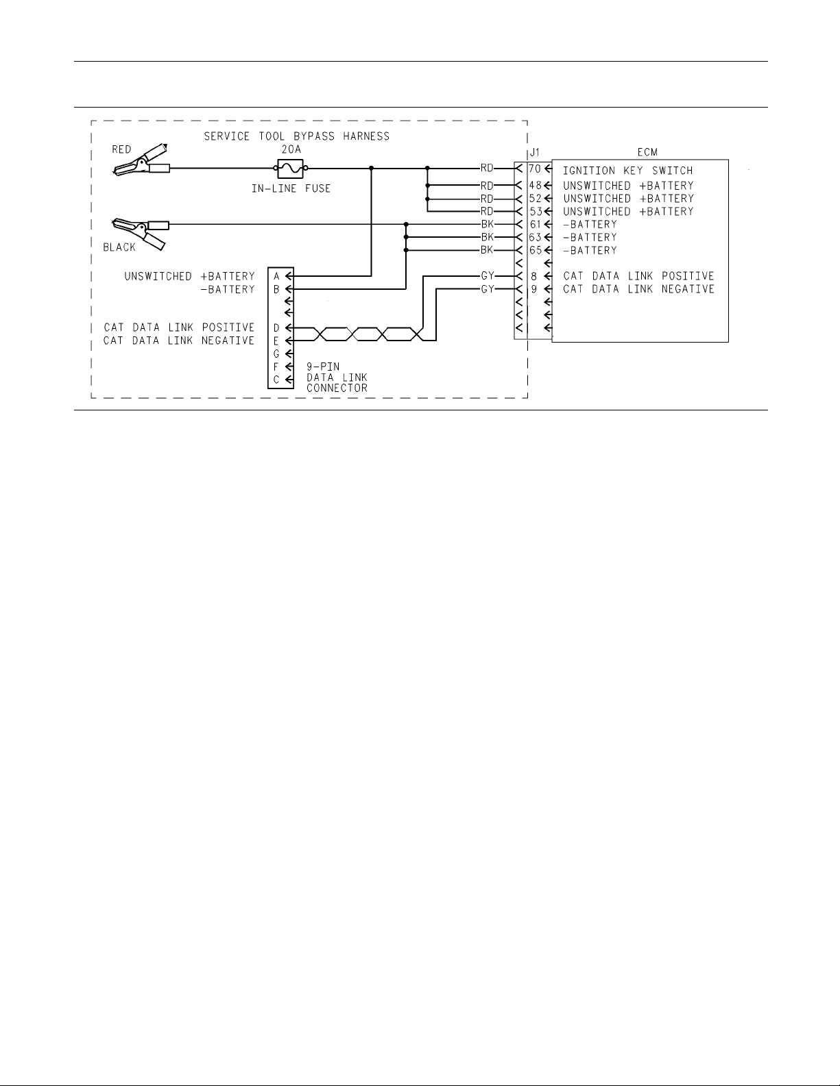
34 RENR5042-02
Troubleshooting Section
Illustration 9
Direct connection of Cat ET to the P1 connector
If the engine is cranking and Cat ET displays zero
rpm, a problem exists in the circuits for the engine
speed/timing sensors. Refer to Troubleshooting,
“Engine Speed/Timing Sensor Circuit - Test”.
If an engine speed is present, check the sensor
installation. If the sensor is not properly installed,
the ECM may read engine speed, but the ECM
cannot determine the tooth pattern. The ability for
the ECM to read the tooth pattern is necessary to
determine the cylinder position. Engine speed is
present when engine speed is greater than 50 rpm.
Refer to Troubleshooting, “Engine Speed/Timing
Sensor Circuit - Test”.
Electrical Connections to the Electronic
Unit Injector
1. Ensure that the electronic unit injector connector
(J300/P300) is fully connected and free of
corrosion.
2. Check for logged diagnostic codes that are related
to the cylinder. Refer to Troubleshooting, “Injector
Solenoid Circuit - Test” if diagnostic codes that are
related to the cylinder are present.
g00781203
If no smoke is present, there may be a problem
with the fuel quality or there may be a problem
with the fuel supply.
3. Check the fuel pressure. Refer to Systems
Operation/Testing and Adjusting, “Fuel System
Pressure - Test”.
4. Ensure that the fuel system has been primed.
Refer to Systems Operation/Testing and Adjusting,
“Fuel System - Prime”.
5. Check for fuel supply lines that are restricted.
6. Check the fuel filters.
7. Cold weather adversely affects the characteristics
of the fuel. Refer to the Operation and
Maintenance Manual for information on improving
the characteristics of the fuel during cold weather
operation.
Check for Combustion Problems
Examples of conditions that may cause combustion
problems are shown in the following list:
Check the Fuel Supply
1. Check the fuel level.
2. Monitor the exhaust for smoke while the engine
is being cranked.
Cold temperatures
•
Injector misfiring
•
Low compression
•
Mechanical problem
•
Valvelashsettings
•
Page 35

RENR5042-02 35
Troubleshooting Section
Refer to the engine’s Systems Operation/Testing
and Adjusting f
problem.
Engine Has Ear
SMCS Code: 1000-035
ormoreinformationonaparticular
i02170800
ly Wear
Probable Causes
Incorrect engine oil
•
Contaminate
•
Contaminated air
•
Contaminated fuel
•
Low oil press
•
Recommended
Incorrect Engine Oil
d engine oil
ure
Actions
Low Oil P ressure
When some components of the engine show bearing
wear in a short time, the cause can be a restriction in
a passage for e
An indicator for the engine oil pressure may indicate
sufficient pr
to a lack of lubrication. In such a case, look at the
passage for the engine oil supply to the component.
Refer to Syst
“Lubrication System” for additional information.
ngine oil.
essure, but a component is worn due
ems Operation/Testing and Adjusting,
i02290324
Engine Misfires, Runs Rough
or Is Unstable
SMCS Code: 1000-035
Note: If the symptom is intermittent and the symptom
cannot be repeated, refer to Troubleshooting,
“Intermittent Low Power or Power Cutout”. If the
symptom is consistent and the symptom can be
repeated, continue with this procedure.
Use engine oil that is recommended and change the
engine oil at the interval that is recommended by the
engine’s Ope
ration and Maintenance Manual.
Contaminated Engine Oil
Drain the crankcase and refill the crankcase with
clean engine oil. Install new engine oil filters. Refer
to the engin
for more information.
If the oil fi
filtered. Check the oil filter bypass valve for a weak
spring or for a broken spring. If the spring is broken,
replace th
and Assembly manual. Make sure that the oil bypass
valve is operating correctly.
e’s Operation and Maintenance Manual
lter bypass valve is open, the oil will not be
e spring. Refer to the engine’s Disassembly
Contaminated Air
Inspect th
the gaskets and the connections. Repair any leaks.
Inspect t
e air inlet system for leaks. Inspect all of
he air filter. Replace the air filter, if necessary.
Contaminated Fuel
Inspect the fuel filter. Replace the fuel filter, if
necessary.
Contaminants in the fuel such as hydrogen sulfide
and sulfur can lead to the formation of acids in the
crankcas
e. Obtain a fuel analysis.
Probable Causes
Diagnostic codes
•
Programmable parameters
•
Electrical connectors
•
Cold mode
•
Throttle signal
•
Unit injectors
•
Fuel supply
•
Air inlet and exhaust system
•
Recommended Actions
Note: If the symptom only occurs under certain
operating conditions (high idle, full load, engine
operating temperature, etc), test the engine under
those conditions. Troubleshooting the symptom
under other conditions can give misleading results.
Diagnostic Codes
Check for active diagnostic codes on the Caterpillar
Electronic Technician (ET). Troubleshoot any active
codes before continuing with this procedure.
Programmable Parameters
Check the following parameters on Cat ET:
Page 36

36 RENR5042-02
Troubleshooting Section
ThrottlePositionSensor
•
Desired Speed Input Configuration
•
Direct Fuel Con
•
Determine the type of throttle that is used in the
application.
type of throttle that is used. Refer to Troubleshooting,
“Throttle Position Sensor Circuit - Test” for more
information.
Note: The engine will have poor performance if the
parameters a
trol Mode
Program the parameters to match the
re not programmed correctly.
Electrical Connectors
Check for correct installation of the Electronic Control
Module (ECM) connectors and the unit injector
connectors.
Connectors - Inspect”.
Refer to Troubleshooting, “Electrical
Cold Mode
Use Cat ET to verify that the engine has exited cold
mode. Cold m
run rough and the engine power may be limited.
Throttle Si
Monitor the throttle signal on Cat ET. Verify that the
throttle si
thehighidleposition.
Unit Injec
1. Use Cat ET to determine if there are any active
diagnosti
2. Perform the injector solenoid test on Cat ET in
order to de
are being energized by the ECM. Refer to
Troubleshooting, “Injector Solenoid Circuit - Test”
for the pro
3. Perform the cylinder cutout test on Cat ET in order
to identif
Refer to Troubleshooting, “Injector Solenoid
Circuit - Test” for the proper procedure.
ode operation may cause the engine to
gnal
gnal is stable from the low idle position to
tors
c codes for the unit injectors.
termine if all of the injector solenoids
per procedure.
y any injectors that might be misfiring.
3. Check for air in the low pressure fuel supply
system if any of
been performed:
Replacement o
•
Service o n the low pressure fuel supply circuit
•
Replacement of unit injectors
•
4. Purge air from
Refer to Operation and Maintenance Manual,
“Fuel System - Prime” for the complete procedure.
Note: A sight glass in the low pressure supply line is
helpful in diagnosing air in the fuel.
5. Cold weather adversely affects the characteristics
of the fuel. Refer to the Operation and
Maintenance
the characteristics of the fuel during cold weather
operation.
6. Check the fuel pressure during engine cranking.
Check the fuel pressure after the fuel filter. Refer
to Systems O
System” for the correct pressure values. If the fuel
pressure is low, replace the fuel filters. If the fuel
pressure is
transfer pump, fuel transfer pump coupling, and
fuel pressure regulating valve.
the following procedures have
f the fuel filters
the low pressure fuel supply circuit.
Manual for information on improving
peration/Testing and Adjusting, “Fuel
still low, check the following items: fuel
Air Inlet and Exhaust System
1. Check for a
filters or replace plugged air filters. Refer to the
Operation and Maintenance Manual for additional
informat
2. Check the air inlet and exhaust system for
restrict
Operation/Testing and Adjusting, “Air Inlet and
Exhaust System”.
n air filter restriction. Clean plugged air
ion.
ions and/or for leaks. Refer to Systems
i02173692
Engine Oil in Cooling System
SMCS Code: 1348-035; 1350-035
Fuel Supply
1. Check the
restrictions, collapsed lines, and pinched lines. If
problems are f ound with the fuel lines, repair the
lines an
2. Check the fuel tank for foreign objects which may
block th
fuel lines for the following problems:
d/or replace the lines.
e fuel supply.
Probable Causes
Engine oil cooler core
•
Cylinder head gasket
•
Page 37

RENR5042-02 37
Troubleshooting Section
Recommended Ac
tions
Engine Oil Cooler C ore
1. Inspect the engine oil cooler core for leaks. If a
leak is found, replace the oil cooler core. Refer to
Disassembly a
Remove”.
2. Drain the cran
clean engine oil. Install new engine oil filters.
Refer to the Operation and Maintenance Manual
for more info
nd Assembly, “Engine Oil Cooler -
kcase and refill the crankcase with
rmation.
Cylinder Head Gasket
1. Remove the cylinder head. Refer to Disassembly
and Assembly, “Cylinder Head - Remove” for the
correct proc
2. Check the cylinder liner projection. Refer to
Systems Ope
correct procedure.
3. Install a ne
seals in the spacer plate. Refer to Disassembly
and Assembly, “Cylinder Head - Install” for the
correct pro
edure.
ration/Testing and Adjusting for the
w cylinder head gasket and new water
cedure.
Engine Oil Temperature Reading
Compare the engine oil temperature reading from
the Caterpillar Electronic Technician (ET) to the
temperature f
(MULTIMETER). Verify that the readings are
reasonably close.
rom a 6V-9130 Temperature Adapter
Coolant temperature
If a high coola
occurring, refer to Troubleshooting, “Coolant
Temperature is Too High”.
nt temperature condition is also
Engine Oil Cooler Bypass Valve
Clean the eng
the engine oil cooler bypass valve. Clean the bore for
the valve. Ensure that the bypass valve is not stuck
in the open po
necessary.
Engine Oil C
Clean the engine oil cooler core or replace the engine
oil cooler c
ine oil cooler bypass valve and inspect
sition. Replace the bypass valve, if
ooler Core
ore.
i02253823
i02214225
Engine Oil Temperature Is Too
High
SMCS Code: 1348-035-TA
Probable Causes
Engine oil level
•
Engine oil
•
Coolant temperature
•
Engine oil cooler bypass valve
•
Engine oil
•
Recommen
Engine Oil Level
Inspect the engine oil level. If necessary, add oil.
temperature reading
cooler core
ded Actions
Engine Stal
SMCS Code: 1915-035
ls at Low RPM
Probable Causes
Unit injectors
•
Fuel supply
•
Accessory equipment
•
Recommended Actions
Unit Injectors
1. Check for co
J2/P2 connectors for the Electronic Control
Module (ECM). Check for correct installation of
the J300/P
Refer to Troubleshooting, “Electrical Connectors
- Inspect”.
2. Perform the “Injector Solenoid Test” with the
Caterpillar Electronic Technician (ET) in order to
determin
energized by the ECM.
rrect installation of the J1/P1 and
300 connectors for the unit injectors.
e if all of the injector solenoids are being
3. Perform t
in order to identify any injectors that might be
misfiring. Refer to Troubleshooting, “Injector
Solenoid
he “Cylinder Cutout Test” with Cat ET
Circuit - Test” for the proper procedure.
Page 38

38 RENR5042-02
Troubleshooting Section
Fuel Supply
1. Check the fuel pressure. Refer to Systems
Operation/Testing and Adjusting, “Fuel System”
for the correc
2. Check the fuel lines for the following problems:
restrictions
problems are f ound with the fuel lines, repair the
lines and/or replace the lines.
3. Check the fuel tank for foreign objects which may
block the fuel supply.
4. Check for air in the low pressure fuel supply
system if any of the following procedures have
been perform
Replacement of the fuel filters
•
Service on the low pressure fuel supply circuit
•
Replacement
•
Note: A sight glass in the low pressure supply line is
helpful in d
Operation/Testing and Adjusting, “Fuel System” for
more information.
t procedure.
, collapsed lines, and pinched lines. If
ed:
of unit injectors
iagnosing air in the fuel. Refer to Systems
i02214232
Engine Vibration
SMCS Code: 1000
Probable Cause
Vibration damper
•
Engine supports
•
Driven equipm
•
Engine misfiring or running rough
•
Recommended Actions
Vibration Damper
Check the vibr
new vibration damper, if necessary. Inspect the
mounting bolts for damage and/or for wear. Replace
any damaged b
Assembly manual.
Engine Suppo
-035
s
ent
ation damper for damage. Install a
olts. Refer to the Disassembly and
rts
NOTICE
Do not crank
30 seconds. Allow the starting motor to cool for two
minutes before cranking the engine again.
5. Purge air from the low pressure fuel supply circuit.
Refer to the Operation and Maintenance Manual,
“Fuel Syst
6. Cold weather adversely affects the characteristics
of the fuel
Maintenance Manual for information on improving
the characteristics of the fuel during cold weather
operation
7. Check the fuel pressure after the fuel filter while
the engine
Operation/Testing and Adjusting manual for the
correct pressure values. If the fuel pressure is low,
replace t
low, check the following items: fuel transfer pump,
fuel transfer pump coupling, and fuel pressure
regulat
the engine continuously for more than
em - Prime” for the correct procedure.
. Refer to the applicable Operation and
.
is being cranked. Refer to the Systems
he fuel filters. If the fuel pres sure is still
ing valve.
Accessory Equipment
Check all accessory equipment for problems that
may create excessive load on the engine. Repair
any dama
components.
ged components or replace any damaged
Inspect the mounts and the brackets while you run
the engine th
and brackets that are loose and/or broken. Tighten
all of the mounting bolts. Install new components, if
necessary.
rough the speed range. Look for mounts
Driven Equipment
Check the alignment and the balance of the driven
equipment.
Engine Misfiring or Running Rough
Refer to Tro
Rough or Is Unstable”.
ubleshooting, “Engine Misfires, Runs
i02214238
Engine Will Not Crank
SMCS Code: 1000-035
Probable Causes
Batteries
•
Battery cables
•
Starting circuit
•
Page 39

RENR5042-02 39
Troubleshooting Section
Starting motor solenoid
•
Starting motor
•
Flywheel ring g
•
Transmission
•
Engine accessories
•
Hydraulic cyl
•
Internal engine problem
•
ear
inder lock
Recommended Actions
Batteries and/or Battery Cables
1. Inspect the ma
and battery cables for loose connections and
for corrosion. If the battery cables are corroded,
remove the ba
cables. Tighten any loose connections.
2. Inspect the b
a. Charge the batteries. Refer to Special
Instruction
Procedure”.
b. Load test the
Instruction, SEHS9249, “Use of 4C-4911
Battery Load Tester for 6, 8 and 12 Volt Lead
Acid Batter
in power switch, battery posts,
ttery cables and clean the battery
atteries.
, SEHS7633, “Battery Test
batteries. Refer to Special
ies”.
The following list illustrates examples of engine
accessories th
Hydraulic pump that is driven from the rear gear
•
group
Air compressor
•
Engine oil pump
•
Other compone
•
at may lock up the engine:
nts that are driven by the engine
Hydraulic Cylinder Lock
Check for fluid in the cylinders (hydraulic cylinder
lock) by removing the individual unit injectors.
Note: Drain the fuel from the cylinder head. Fuel will
flow from the cylinder head into the cylinders when
the unit injec
tor is removed.
Internal Engine Problem
Disassemble the engine. Refer to the Disassembly
and Assembly manual. Inspect the internal
components f
Seizure
•
Broken components
•
Bent compone
•
or the following conditions:
nts
i02280902
Starting Motor Solenoid or Starting
Circuit
1. Test the operation of the starting motor solenoid.
2. Check the wiring to the starting motor solenoid.
Starting Mo
1. Test the operation of the starting motor.
2. Inspect the starter motor pinion and the flywheel
ring gear for damage.
tor or Flywheel Ring Gear
Transmission or Engine Accessories
1. Ensure fre
2. Ensure that the timing pin was not left in the
flywheel h
3. Remove any engine accessories that may lock up
the engine
that may lock up the engine.
e movement of the driveline.
ousing.
and inspect any engine accessories
Excessive Black Smoke
SMCS Code: 1088-035
Probable Causes
Air inlet an
•
Engine speed/timing sensor
•
Atmospheric pressure sensor
•
Boost press
•
“Fuel Position” and/or “FRC Fuel Limit”
•
Flash file
•
Fuel qualit
•
Valve adjustment
•
d exhaust system
ure sensor
y
Page 40

40 RENR5042-02
Troubleshooting Section
Recommended Ac
tions
Air Inlet and Exhaust System
1. Check the air inlet system for restrictions and/or
for leaks.
a. Check for an air filter restriction.
b. Check for dera
c. Perform a visual inspection of the system for
restrictions
2. Ensure that the turbocharger has not failed.
3. Check the exhaust system for restrictions.
4. Repair any lea
any restrictions that were found. Replace any
damaged components that were found.
tes and for alarms.
and/or for leaks.
ks that were found. Remove
Engine Speed/Timing
1. Check the cal
sensor. Refer to Troubleshooting, “Engine
Speed/Timing Sensor - Calibrate”.
2. Verify that the crankshaft and the camshaft drive
gears are set with the proper orientation. Refer to
the Disassem
ibration of the engine speed/timing
bly and Assembly manual.
Note: A problem with the FRC will only cause black
smoke during ac
will not cause black smoke during steady state
operation.
celeration. A problem with the FRC
Flash File
Verify that th
to Troubleshooting, “Flash Programming” for more
information.
ecorrectflashfileisinstalled.Refer
Fuel Quality
Cold weather
the fuel. Refer to Operation and Maintenance Manual
for information on improving the characteristics of the
fuel during c
adversely affects the characteristics of
old weather operation.
Valve Adjustment
Check the valve adjustment. Refer to Systems
Operation/Testing and Adjusting, “Air Inlet and
Exhaust Sys
tem”.
i01405645
Excessive Engine Oil
Consumption
SMCS Code: 1348-035
Atmospheric Pressure Sensor
Check the atmospheric pressure sensor for dirt
and/or for debris. Remove any dirt and/or debris that
is present.
pressure is between 50 kPa (7.25 psi) and 100 kPa
(14.5 psi).
The correct reading for the atmospheric
Boost Pressure Sensor, “Fuel Position”,
and/or “FRC Fuel Limit”
1. Monitor the status of “Fuel Position” and “Rated
Fuel Limit” while the engine is operating under full
load.If“F
and “Fuel Position” is less than “FRC Fuel Limit”,
the electronics are operating correctly. Otherwise,
proceed t
2. Verify that there are no active diagnostic codes for
the boost
3. Monitor the status of “Boost Pressure” and
“Atmosph
the Caterpillar Electronic Technician (ET). When
the engine is not running, “Boost Pressure” should
be 0 kPa (0
uel Position” equals “Rated Fuel Limit”
o the next Step.
pressure sensor.
eric Pressure” for normal operation on
psi).
Probable Causes
Oil leaks
•
Oil level
•
Engine oil temperature
•
Turbocharger
•
Valve guides
•
Piston rings
•
Recommended Actions
Oil Leaks
Locate all oil leaks. Repair the oil leaks. Check for
dirty crankcase breathers.
Oil Level
Remove excess oil. Locate the source of the excess
fluid. Repair the leaks that are causing the problems.
Recheck all fluid levels.
Page 41

RENR5042-02 41
Troubleshooting Section
Engine Oil Temperature
Refer to Troubleshooting, “Engine Oil Temperature
is Too High”.
Turbocharger
Check the air i
the turbocharger or replace the turbocharger.
nlet manifold for oil. If necessary, repair
Valve Guides
If the valve guides are worn, reconditioning of the
cylinder head
is required.
Piston Rings
Inspect the internal engine components. Replace any
worn components.
i02253900
Excessive Fuel C on sumption
SMCS Code: 12
50-035
Fuel Leaks
Check the fuel pressure during engine cranking.
Check the fuel pressure after the fuel filter. Refer
to Systems Ope
System” for the correct pressure values. If the fuel
pressure is low, replace the fuel filters. If the fuel
pressure is s
transfer pump, fuel transfer pump coupling, and fuel
pressure regulating valve.
ration/Testing and Adjusting, “Fuel
till low, check the following items: fuel
Fuel Quality
Cold weather
of the fuel. Refer to the applicable Operation and
Maintenance Manual for information on improving
the characte
operation.
Engine Spee
Calibrate the engine speed/timing sensors. Refer
to Troubles
-Calibrate”.
Unit Inject
adversely affects the characteristics
ristics of the fuel during cold weather
d/Timing
hooting, “Engine Speed/Timing Sensor
ors
Probable Cau
Engine operation
•
Fuel leaks
•
Fuel quality
•
Engine speed/timing
•
Unit injectors
•
Air inlet an
•
Accessory equipment
•
d exhaust system
ses
Recommended Actions
Engine Operation
Use the Cate
check the “Current Totals” for excessive idle time
and/or for a high load factor which would be indicative
of poor ope
Note: Engine operation may also be affected by
environme
rpillar Electronic Technician (ET) to
rating habits.
ntal conditions such as wind and snow.
1. Check for correct installation of the J1/P1
and J2/P2 E
connectors and the unit injector connectors.
Refer to Troubleshooting, “Electrical Connectors
- Inspect”
2. Perform the “Injector Solenoid Test” on Cat ET in
order to de
are being energized by the ECM.
3. Perform t
in order to identify any injectors that might be
misfiring. Refer to Troubleshooting, “Injector
Solenoid
lectronic Control Module (ECM)
.
termine if all of the injector solenoids
he “Cylinder Cutout Test” on Cat ET
Circuit - Test” for the proper procedure.
Air Inlet and Exhaust System
1. Inspect the air filter for a restriction. If the air filter
shows signs of being plugged, clean the air filter
or replac
2. Check the air inlet and exhaust system for
restric
Operation/Testing and Adjusting, “Air Inlet and
Exhaust System”.
e the air filter.
tions and/or for leaks. Refer to Systems
Accessory Equipment
Check al
may create excessive load on the engine. Repair
any damaged components or replace any damaged
compon
l accessory equipment for problems that
ents.
Page 42

42 RENR5042-02
Troubleshooting Section
i02280972
Excessive Valve Lash
SMCS Code: 1105
Probable Cause
Lubrication
•
Valve lash
•
Valve tr ain co
•
Recommended A
Lubrication
1. Remove the valve mechanism covers. Refer to
the engine’s Disassembly and Assembly manual
for the corre
2. Check the lubrication in the valve compartment.
Ensure that t
the valve compartment. The passages for the
engine oil must be clean.
-035
s
mponents
ctions
ct procedure.
here is adequate engine oil flow in
3. Adjust the engine valve lash. Refer to the engine’s
Systems Operat
for the correct procedure.
Excessive Whi
SMCS Code: 1088-035
Note: Some white smoke may be present during
cold start-up conditions when the engine is operating
normally. If
a problem.
the white smoke persists, there may be
ion/Testing and Adjusting manual
i02290300
te Sm oke
Probable Causes
Diagnostic c
•
Starting aids
•
Water temperature regulators
•
Unit inject
•
Flash file
•
odes
ors
Valve Lash
Adjust the en
Systems Operation/Testing and Adjusting manual for
the correct procedure.
gine valve lash. Refer to the engine’s
Valve Train Components
1. Inspect the
train:
Rocker arms
•
Pushrods
•
Valve lifters
•
Camshaft
•
Valve stems
•
Rocker shafts
•
2. Check the co
abnormal wear, excessive wear, straightness, and
cleanliness. Replace parts, if necessary.
following components of the valve
mponents for the following conditions:
Fuel supply
•
Cooling syst
•
Component wear
•
em
Recommended Actions
Diagnostic Codes
Check for ac
Electronic Technician (ET). Troubleshoot any active
codes before continuing with this procedure.
Starting Aids
Air Inlet He
Ensure that the air inlet heater is functioning properly.
For additio
“Air Inlet Heater Circuit - Test”.
Ether Inje
Ensure that the ether injection system is programmed
to “On”.
tive diagnostic codes on the Caterpillar
ater (If Equipped)
nal information, refer to Troubleshooting,
ction System (If Equipped)
Note: If you replace the camshaft, you must also
replace the valve lifters.
Ensure that the ether injection system is functioning
properly.
Troubleshooting, “Ether Injection System - Test”.
For additional information, refer to
Page 43

RENR5042-02 43
Troubleshooting Section
Water Temperature Regulators
Check the water temperature regulators for correct
operation. Refer to Systems Operation/Testing and
Adjusting, “C
ooling System” for the proper procedure.
Unit Injectors
Use Cat ET to perform the cylinder cutout test. Try
to simulate the conditions for the test that were
experienced d
individually for approximately one minute in order
to isolate any misfiring cylinders. If the misfire
can be isolat
Troubleshooting, “Injector Solenoid Circuit - Test”.
uring operation. Cut out each cylinder
ed to a specific cylinder, proceed to
Flash File
Verify that the correct flash file is installed. The flash
file that is i
(ECM) will be displayed on the “Configuration” screen
on Cat ET.
nstalled in the Electronic Control Module
Fuel Supply
1. Monitor the
is being cranked.
If no smoke i
with the fuel quality or there may be a problem
with the fuel supply.
exhaust for smoke while the engine
s present, there may be a problem
Pistons
•
Rings
•
Cylinder liner
•
s
i02214294
Exhaust Temperature Is Too
High
SMCS Code: 1088-035-TA
Probable Causes
Diagnostic codes
•
Electrical connectors
•
Air inlet and exhaust system
•
Recommended Actions
Diagnostic Codes
Connect the Caterpillar Electronic Technician (ET)
and check for active diagnostic codes. Troubleshoot
any active diagnostic codes before continuing with
this procedure.
2. Check the fuel pressure. Refer to Systems
Operation/Testing and Adjusting, “Fuel System
Pressure -
3. Ensure that the fuel system has been primed.
Refer to Sy
“Fuel System - Prime”.
4. Check for f
5. Cold weather adversely affects the characteristics
of the fue
Maintenance Manual for information on improving
the characteristics of the fuel during cold weather
operatio
Te s t” .
stems Operation/Testing and Adjusting,
uel supply lines that are restricted.
l. Refer to the Operation and
n.
Cooling System
Check for an internal coolant leak. Check for coolant
in the engine oil, coolant in the cylinders, and
coolant
Operation/Testing and Adjusting, “Cooling System Tes t” .
in the exhaust system. Refer to Systems
Component Wear
Electrical Connectors
Check for correct installation of the J2/P2 Electronic
Control Module (ECM) connector and of the
J300/P300 unit injector connectors. Refer to
Troubleshooting, “Electrical Connectors - Inspect”
for more information.
Air Inlet and Exhaust System
1. Check the air inlet manifold pressure. Check for
air inlet restrictions and/or leaks. Refer to Systems
Operation/Testing and Adjusting, “Air Inlet and
Exhaust System” for more information.
2. Check for leaks between the exhaust manifold
and the turbocharger. Check for exhaust
restrictions. Refer to Systems Operation/Testing
and Adjusting, “Air Inlet and Exhaust System” for
more information.
Check th
Valves
•
e following components for excessive wear:
Page 44

44 RENR5042-02
Troubleshooting Section
i01405833
Fuel in Cooling System
SMCS Code: 1350
Probable Cause
Internal cylinder head
•
Recommended Actions
Internal Cylinder Head
1. Remove the val
2. Remove the fuel supply and the fuel return line
from the cylin
3. Cap the fuel return connector and apply 700 kPa
(100 psi) max
connector. Check for fuel leakage around the unit
injectors. If leakage is present, remove the unit
injector and
-035
s
ve mechanism covers.
der head.
imum air pressure to the fuel supply
install a new O-ring seal.
Leaking Seals on the Fuel Line Adapter
for the Cylinde
Look for signs of damage to the seals on the fuel line
adapter for th
lines or components and/or replace any leaking fuel
lines or components.
rHead
e cylinder head. Repair any leaking fuel
Excessive Leakage from the Unit Injector
Tip or Breakage of the Unit Injector Tip
Look for signs of damage to the unit injectors. If
necessary, repair the unit injectors or replace the unit
injectors.
Cracked Fuel Supply Manifold
Look for signs of damage to the fuel supply manifold.
Leaking Fuel
Ensure that the weep hole is not plugged. If
necessary,
the fuel transfer pump.
Transfer Pump Seal
repair the fuel transfer pump or replace
i02119587
Fuel Dilution of Engine Oil
SMCS Code: 1348-035
Probable Causes
Leaking seals on the case of the unit injector or on
•
the barrel of the unit injector
Leaking seals on the fuel line adapter for the
•
cylinder head
Excessive leakage from the unit injector tip or
•
breakage of the unit injector tip
Cracked fuel supply manifold
•
Leaking seal on the fuel transfer pump
•
Recommended Actions
Leaking Seals on the Case of the Unit
Injector or on the Barrel of the Unit
Injector
Look for signs of damage to the seals for the unit
injectors. Replace any seals that are leaking.
i02290607
Intermitte
SMCS Code: 1000-035
Note: Use this procedure only if the engine shut
down completely and it was necessary to restart the
engine.
Probable C
Diagnostic codes or event codes
•
Selected engine rating parameters
•
Electrica
•
Faulty remote shutdown
•
Circuit breakers
•
Fuel suppl
•
Faulty overspeed verify switch
•
Note: If the problem only occurs under certain
conditions such as high engine speed, full load or
engine op
under those operating conditions.
nt Engine Shut do wn
auses
l connections
y
erating temperature, then perform the test
Page 45

RENR5042-02 45
Troubleshooting Section
Recommended Ac
tions
Diagnostic Codes or Event Codes
Certain diagnostic codes and/or event codes
may cause the engine to shutdown. Connect the
Caterpillar E
active codes and/or for logged codes. Troubleshoot
any codes that are present before continuing with
this procedu
lectronic Technician (ET) and check for
re.
Selected Engine Rating Parameters
The engine may be shut down due to low pressure
levels or other factors. Connect Cat ET and check for
active shutd
If a shutdown is active, “Injection Disabled” will
appear in the
ET.
An engine sh
device if the device is capable of displaying diagnostic
codes.
owns or diagnostic codes.
third box of any status screen on Cat
utdown event will appear on a J1939
Electrical Connections
1. Check the fo
installation:
J1/P1 and J2
•
Control Module (ECM)
J61/P61 Cus
•
llowing connectors for proper
/P2 connectors for the Electronic
tomer connectors
Table 13
“User Shutdown” Status
ON <0.9 VDC
OFF >10 VDC
3. If the voltage is not in the proper range, refer to
ubleshooting, “Switch Circuits - Test”.
Tro
Measured Voltage at
J1-44 or P61-27
Circuit Breakers
Check the circuit breakers. The circuit breakers may
exceed the trip point due to overheating. Reset the
rcuit breakers if the circuit breakers are tripped.
ci
Fuel Supply
Check for a problem with the fuel supply. Verify
that the fuel pressure is correct. Verify that the
el pressure sensor is installed. Refer to Systems
fu
Operation/Testing and Adjusting, “Fuel System” for
additional information.
Faulty Overspeed Verify Switch (If
Equipped)
A problem with the circuit for the overspeed verify
feature may be causing the engine to shut down.
here are no diagnostic codes or event codes that
T
are associated with the overspeed verify feature.
Refer to Troubleshooting, “Switch Circuits - Test”.
J300/P300 Connectors for the injector solenoid
•
harness
J401/P401 and J402/P402 Engine speed/timing
•
sensor con
2. Check the associated wiring for the following
condition
incorrect attachment.
Refer to Tr
- Inspect”.
Note: Afte
interrupt power to th e ECM. Check for correct
installation and for operation of aftermarket engine
protecti
the aftermarket devices in order to continue testing.
on devices. It may be necessary to bypass
Faulty Re
1. Access the status screen that displays the remote
shutdown
switch status on Cat ET is called “User Shutdown”.
2. Refer to
each terminal that is listed and the engine ground.
nectors
s: damage, abrasion, corrosion, and
oubleshooting, “Electrical Connectors
rmarket engine protection devices usually
mote Shutdown
switch status. The remote shutdown
Table 13. Measure the voltage between
i02290319
Intermittent Low Power or
Power Cutout
SMCS Code: 1000-035
Note: Use this procedure only if the engine does not
shut down completely.
Probable Causes
Diagnostic codes
•
Event codes
•
Throttle signal
•
Electrical connectors
•
Fuel supply
•
Page 46

46 RENR5042-02
Troubleshooting Section
Recommended Ac
tions
Diagnostic Codes and Event Codes
Certain diagnostic codes and/or event codes may
cause poor performance. Connect the Caterpillar
Electronic Te
and logged codes. Troubleshoot any codes that are
present before continuing with this procedure.
chnician (ET) and check for active codes
Throttle Signal
Connect Cat ET
the status for the throttle position on the status
screen. Operate the throttle from the low idle position
tothehighid
percent at low idle and the status should be 100
percent at high idle. Refer to Troubleshooting,
“Throttle Po
is incorrect.
Diagnostic
link will prevent correct operation of the throttle if the
throttle position is transmitted over the data link. If
there is a p
remain at low idle until the data link is repaired.
Electrica
1. Inspect the battery wires from the Electronic
Control Mo
compartment. Refer to the Electrical System
Schematic. Inspect the wires and the power relay.
Check the p
the ECM. Refer to the diagnostic functional test
Troubleshooting, “Electrical Power Supply Circuit
- Test” fo
to the service tool connector. View
le position. The status should be 0
sition Sensor - Calibrate” if either value
codesthatarerelatedtotheJ1939data
roblemwiththedatalink,theenginewill
l Connectors
dule (ECM) back to the battery
ower and ground connections to
r more information.
Note: A sight glass in the low pressure supply line is
helpful in diag
Operation/Testing and Adjusting, “Fuel System” for
more information.
Do not crank the
30 seconds. Allow the starting motor to cool for two
minutes before cranking the engine again.
4. Purge air from the low pressure fuel supply circuit.
Refer to Operation and Maintenance Manual,
“Fuel System
5. Cold weather adversely affects the characteristics
of the fuel. R
Maintenance Manual for information on improving
the characteristics of the fuel during cold weather
operation.
6. Check the fuel pressure after the fuel filter while
the engine i
Operation/Testing and Adjusting, “Fuel System
Pressure - Test” for the correct pressure values.
If the fuel p
If the fuel pressure is still low, check the following
items: fuel transfer pump, fuel transfer pump
coupling,
to Systems Operation/Testing and Adjusting, “Fuel
System” for additional information.
nosing air in the fuel. Refer to Systems
NOTICE
engine continuously for more than
- Prime” for the correct procedure.
efer to the Operation and
s being cranked. Refer to Systems
ressure is low, replace the fuel filters.
and fuel pressure regulating valve. Refer
i02171503
Low Engin e Oil Pressu re
SMCS Code: 1348-035-LP
Fuel Supply
1. Check the fuel lines for the following problems:
restrictions, collapsed lines, and pinched lines. If
problem
lines and/or replace the lines.
2. Check th
block the fuel supply.
3. Check fo
system if any of the following procedures have
been performed:
•
•
•
s are found with the fuel lines, repair the
e fuel tank for foreign objects which may
r air in the low pressure fuel supply
Replacement of the fuel filters
Service
Replacement of unit injectors
on the low pressure fuel supply circuit
NOTICE
Do not operate the engine with low oil pressure.
Engine damage will result. If measured oil pressure is
low, discontinue engine operation until the problem is
corrected.
Refer to Systems Operation/Testing and Adjusting,
“Lubrication System” for information on engine oil
pressure.
i02290611
Low Power/Poor or No
Response to Throttle
SMCS Code: 1000-035
Probable Causes
Diagnostic codes
•
Page 47

RENR5042-02 47
Troubleshooting Section
Event codes
•
Engine rating
•
Programmable p
•
Cold mode
•
Altitude derate
•
Electrical co
•
PTO enable switch
•
Intermediate speed switch
•
Throttle sign
•
Circuit for electronic unit injectors
•
Fuel supply
•
Boost pressur
•
fuel position and/or FRC fuel position
Air inlet and e
•
arameters
nnectors
al
e sensor (intake manifold air), rated
xhaust system
Determine the type of throttle that is used in the
application. P
type of throttle that is used. Refer to Troubleshooting,
“Throttle Position Sensor Circuit - Test” for more
information.
Note: The engine will have poor performance if the
parameters a
rogram the parameters to match the
re not programmed correctly.
Cold Mode
Monitor the status screen on Cat ET in order to verify
that the engine has exited cold mode. Observe the
reading for c
engine should exit cold mode whenever the coolant
temperature is above 18 °C (64 °F).
oolant temperature on Cat ET. The
Altitude Derate
Theenginema
Connect Cat ET to the service tool connector. Check
for an active engine derate on the status screens.
Note: There are no event codes that are associated
with the altitude derate.
ybederatedduetohighelevation.
Recommended A
Note: If the problem only occurs under certain
conditions, t
Examples of certain conditions are high rpm, full load
and engine operating temperature. Troubleshooting
the symptoms
misleading results.
Diagnostic C
Certain diagnostic codes and/or event codes may
cause poor p
Electronic Technician (ET) and check for active codes
and for logged codes. Troubleshoot any codes that
are present
est the engine under those conditions.
under other conditions can give
odes and Event Codes
erformance. Connect the Caterpillar
before continuing with this procedure.
ctions
Engine Rating
Verify that the correct engine rating is being used for
the application.
Programmable Parameters
Check the f
ThrottlePositionSensor
•
Desired Speed Input Configuration
•
Direct Fuel
•
ollowing parameters on Cat ET:
Control Mode
Electrical Connections to the Electronic
Control Module (ECM)
Check the associated wiring for damage, abrasion,
corrosion or incorrect attachment on the following
connector
J61/P61 customer connector (optional), and
J403/P403 throttle position sensor connector. Refer
to Troubl
for additional information.
PTO Enabl
Connect Cat ET and verify that the “PTO Enable
Switch” i
parameter does not match the position of the switch,
there is a problem with the circuit for the PTO enable
switch. R
Tes t” .
If the va
matches the position of the switch, continue to next
step.
s. J1/P1 and J2/P2 ECM connectors,
eshooting, “Electrical Connectors - Inspect”
eSwitch
s “Not Engaged”. If the value of the
efer to Troubleshooting, “Switch Circuits -
lue of the “PTO Enable Switch” parameter
Intermediate Spe ed Switch
Verify t
Switch”matchesthepositionoftheswitch.Ifthe
value of the parameter does not match the position
of the s
for the switch for the intermediate speed. Refer to
Troubleshooting, “Switch Circuits - Test”.
hat the value of the “Intermediate Speed
witch, there is a problem with the circuit
Verify that the injector trim files are programmed.
Page 48

48 RENR5042-02
Troubleshooting Section
If the value of the “Intermediate Speed Switch”
parameter matc
continue to next step.
Throttle Sign
View the status for the throttle position on the status
screen. Opera
to the high idle position. The status should be 0
percent at low idle and the status should be 100
percent at hi
the full range, refer to Troubleshooting, “Throttle
Position Sensor - Calibrate”.
Diagnostic codes that are related to the J1939 data
link will prevent correct operation of the throttle if the
throttle pos
thereisaproblemwiththedatalink,theenginewill
remain at low idle until the data link is repaired.
hes the position of the switch,
al
tethethrottlefromthelowidleposition
gh idle. If the status cannot operate in
ition is transmitted over the data link. If
Circuit for the Electronic Unit Injector
Inspect the
unit injector connector for proper connections. Refer
to Troubleshooting, “ Electrical Connectors - Inspect”.
Cut out eac
cylinder or cylinders. If the results are inconclusive,
shut off half of the cylinders and repeat the cylinder
cutout tes
in order to locate those cylinders that are missing.
Refer to Troubleshooting, “Injector Solenoid Circuit Tes t” .
J2/P2 ECM connector and the J300/P300
h cylinder in order to isolate the misfiring
t on the active cylinders that are remaining
Note: Atmospheric pressure is not a default
parameter on th
e status screen.
Air Inlet and Exhaust System
Check the air inlet and exhaust systems for
restrictions and for leaks. Refer to Systems
Operation/Te
Exhaust System”. Look for an indication of the
warning lamp or restriction indicators that are
tripped if th
These indicators are associated with plugged filters.
Replace the plugged air filters or clean the plugged
air filters a
Operation and Maintenance Manual. Repair any
leaks that are found in the system.
sting and Adjusting, “Air Inlet and
e filters are equipped with these devices.
ccording to the guidelines in the engine’s
i02281043
Mechanical Noise (Knock) in
Engine
SMCS Code: 1000-035
Probable Causes
Driven equipment
•
Cylinder head and related components
•
Gear train
•
Fuel Supply
Check for a problem with the fuel supply and verify
the fuel pressure. Verify that the fuel pressure sensor
P209/J20
to Systems Operation/Testing and Adjusting, “Fuel
System”.
9 is installed. For further information, refer
Boost Pressure Sensor (Intake Manifold
Air), Rated Fuel Position and/or FR C Fuel
Positio
1. With the engine at full load, monitor “Fuel Position”
2. Verify that there are no active diagnostic codes
3. Monitor air inlet manifold pressure and
n
and “Rat
“Fuel Position” does not equal “Rated Fuel Limit”,
then check air inlet manifold pressure.
that are associated with the boost pressure sensor
or with
atmosp
status screen.
ed Fuel Limit” on the status screen. If
the atmospheric pressure sensor.
heric pressure for normal operation on the
Crankshaft and related components
•
Piston
•
Recommended Repairs
Driven Equipment
Inspect the alignment and the balance of the driven
equipment. Inspect the coupling. If necessary,
disconnect the driven equipment and test the engine.
Cylinder Head and Related Components
Inspect the components of the valve train for good
condition. Check for signs of damage and/or wear
to the valves, cylinder head gasket, etc. Inspect the
condition of the camshafts. If a camshaft is replaced,
new valve lifters must be installed.
Gear Train
Inspect the condition of the gear train.
Page 49

RENR5042-02 49
Troubleshooting Section
Inspect the engine oil filters for nonferrous material.
Flaking of nonf
gear train bearings.
errous material could indicate worn
Crankshaft
Inspect the crankshaft and the related components.
Inspect the co
surfaces on the crankshaft. Make sure that the
bearings are in the correct position.
Look for worn thrust plates and wear on the
crankshaft.
Check the counterweight bolts.
nnecting rod bearings and the bearing
Piston
Make sure that the piston pin is correctly installed.
Inspect the condition of the pistons according
to Guidelines for Reusable Parts and Salvage
Operations
.
i02257027
Noise Comi ng from Cy linder
SMCS Code: 1000-035
Probable Causes
Diagnostic
•
Fuel quality
•
Unit injectors
•
Valve lash
•
codes
Unit Injectors
1. Check for correct installation of the J1/P1
and J2/P2 Electronic Control Module (ECM)
connectors an
connectors. Refer to Troubleshooting, “Electrical
Connectors - Inspect”.
2. Perform the “Injector Solenoid Test” on Cat ET in
order to determine if all of the injector solenoids
are being ene
3. Perform the “Cylinder Cutout Test” on Cat ET
in order to id
misfiring. Refer to Troubleshooting, “Injector
Solenoid Circuit - Test” for additional information.
d the J300/P300 unit injector
rgized by the ECM.
entify any injectors that might be
Valve Lash
Refer to Trou
bleshooting, “Excessive Valve Lash”.
i02290312
Poor Acceleration or Response
SMCS Code: 1000-035
Probable Causes
Engine “Derated”
•
Cold mode operation
•
Flash file
•
Throttle position sensor
•
Electrical connectors
•
Unit injectors
•
Recommende
d Actions
Diagnostic Codes
Check for active diagnostic codes on the Caterpillar
Electronic Technician (ET). Troubleshoot any active
codes befo
re continuing with this procedure.
Fuel Quality
Refer to Operation and Maintenance Manual for
information on improving the characteristics of the
fuel durin
g cold weather operation.
Fuel Position, Rated Fuel Limit, and FRC Fuel
•
Position
Air inlet and exhaust system
•
Fuel supply
•
Recommended Actions
Engine “Derated”
The engine may be derated due to dirty air filters
or other factors. Use the Caterpillar Electronic
Technician (ET) in order to check for engine derates.
Page 50

50 RENR5042-02
Troubleshooting Section
Cold Mode Operation
Monitor the status screen on Cat ET in order to verify
that the engine has exited cold mode. Observe the
reading for co
to Troubleshooting, “System Overview” for additional
information.
olant temperature on the Cat ET. Refer
Flash File
Verify that th
e correct flash file is installed.
Throttle Position Sensor
Monitor “Throttle Status” on Cat ET. Verify that the
throttle position is stable and that the engine is able
to reach high
“Throttle Position Sensor Circuit - Test” for the proper
troubleshooting procedure.
idle rpm. Refer to Troubleshooting,
Electrical Connectors
Check for co
connectors for the Electronic Control Module (ECM).
Check for correct installation of the JH300/P300
unit inject
“Electrical Connectors - Inspect”.
Unit Inject
1. Use Cat ET to determine if there are any active
diagnostic
2. Perform the injector solenoid test on Cat ET in
order to de
are being energized by the ECM. Refer to
Troubleshooting, “Injector Solenoid Circuit - Test”
for the pro
rrect installation of the J1/P1 and J2/P2
or connectors. Refer to Troubleshooting,
ors
codes for the unit injectors.
termine if all of the injector solenoids
per procedure.
3. Monitor the “Boost Pressure” and “Atmospheric
Pressure” for n
is not running, “Boost Pressure” should be 0 kPa
(0 psi).
ormal operation. When the engine
Air Inlet and Exhaust System
1. Check for an ai
plugged air filters or replace plugged air filters.
Refer to the Operation and Maintenance Manual.
2. Check the air inlet and exhaust system for
restrictions and/or leaks. Refer to Systems
Operation/T
Exhaust System”.
r filter restriction indicator. Clean
esting and Adjusting, “Air Inlet and
Fuel Supply
1. Check the fuel lines for the following problems:
restriction
problems are found with the fuel lines, repair the
lines and/or replace the lines.
2. Check the fuel tank for foreign objects which may
block the fuel supply.
3. Check for air in the low pressure fuel supply
system if any of the following procedures have
been perfo
Replacement of the fuel filters
•
Service o n the low pressure fuel supply circuit
•
Replacemen
•
Note: A sight glass in the low pressure supply line is
helpful in
and Adjusting for more information.
s, collapsed lines, and pinched lines. If
rmed:
t of unit injectors
diagnosing air in the fuel. Refer to Testing
3. Perform the cylinder cutout test on Cat ET in order
to identi
Refer to Troubleshooting, “Injector Solenoid
Circuit - Test” for the proper procedure.
fy any injectors that might be misfiring.
Fuel Position, Rated Fuel Limit, and FRC
Fuel Position
1. Monitor the status of “Fuel Position” and “Rated
Fuel Limit” while the engine is operating under full
load. If
and “Fuel Position” is less than “FRC Fuel Limit”,
the electronics are operating correctly. Otherwise,
proceed
2. Verify that there are no active diagnostic codes for
the boos
“Fuel Position” equals “Rated Fuel Limit”
to the next Step.
t pressure sensor.
NOTICE
Do not cran
30 seconds. Allow the starting motor to cool for two
minutes before cranking the engine again.
4. Purge air from the low pressure fuel supply circuit.
Refer to Operation and Maintenance Manual,
“Fuel Syst
5. Cold weather adversely affects the characteristics
of the fue
Maintenance Manual for information on improving
the characteristics of the fuel during cold weather
operatio
k the engine continuously for more than
em - Prime” for the correct procedure.
l. Refer to the Operation and
n.
Page 51

RENR5042-02 51
Troubleshooting Section
6. Check the fuel pressure after the fuel filter while
theengineisbe
Adjusting for the correct pressure values. If the
fuel pressure is low, replace the fuel filters. If
the fuel press
items: fuel transfer pump, fuel transfer pump
coupling, and fuel pressure regulating valve. Refer
to Systems Op
more information.
ing cranked. Refer to Testing and
ure is still low, check the following
eration/Testing and Adjusting for
i01405939
Valve Rotator or Spring Lock
Is Free
SMCS Code: 1109-035
Probable Causes
Cracked valv
•
Broken spring locks
•
Broken valve spring(s)
•
Broken valv
•
Recommende
1. Determinethecauseofanengineoverspeedthat
would crack
2. Inspect the following components for damage:
Valve rotators
•
Spring lock
•
Valve springs
•
Valves
•
Note: Ensur
piston. If the valve has contacted the piston, check
the exhaust system for debris.
e rotator
e
d Actions
the valve rotator. Repair the condition.
s
e that the valve has not contacted the
3. Replace any damaged components.
Page 52
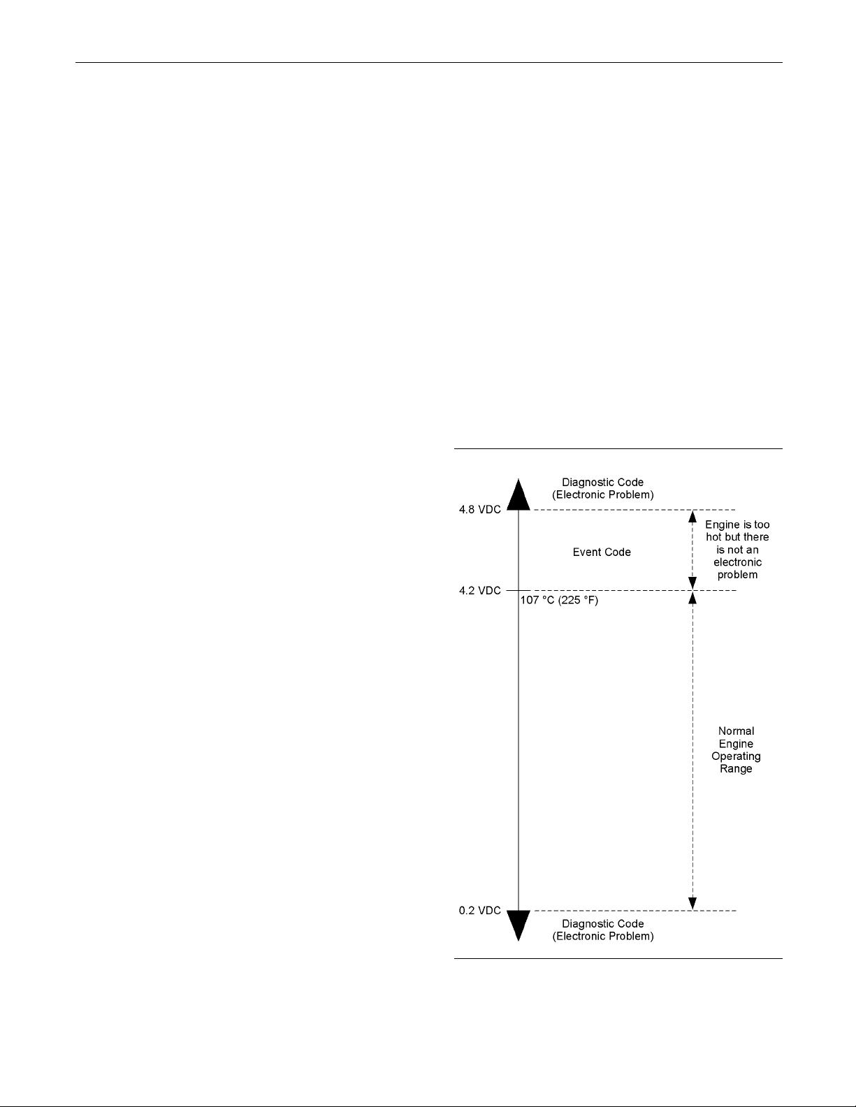
52 RENR5042-02
Troubleshooting Section
Troubleshooti
ng with a
Diagnostic Code
i02085761
Flash Codes
SMCS Code: 1900
Flash codes are a simple way to alert the operator
that a problem exists with the engine’s control system
or with the engine’s operation. Each flash code is
a two digit number. The diagnostic lamp flashes in
order to identify the flash code.
EXAMPLE
Note: Flash Code 27 would flash on the diagnostic
lamp in the following manner:
Two short flashes
•
Hesitation
•
Seven short flashes
•
Refer to Troubleshooting, “Diagnostic Code Cross
Reference” for
codes and a description of each code. There is a
troubleshooting procedure for every diagnostic code.
Refer to Troub
Diagnostic Code”.
Whenadiagno
Control Module (ECM) transmits information about
the code over the J1939 data link. Some J1939
devices may d
will be displayed with a SPN-FMI code. Refer to
Troubleshooting, “Diagnostic Code Cross Reference”
for a crossdiagnostic codes.
Do not confu
Event codes alert the operator that an abnormal
operating condition such as low oil pressure or high
coolant tem
Troubleshooting, “Troubleshooting with an Event
Code” for additional information on event codes.
the complete list of the diagnostic
leshooting, “Troubleshooting With A
stic code is activated, the Electronic
isplay the code. However, the code
reference between SPN-FMI codes and
se diagnostic codes with event codes.
perature has been detected. Refer to
For the descriptions of the flash codes, refer to
Troubleshooting, “Diagnostic Code Cross Reference”.
i02286316
Diagnostic Codes
SMCS Code:
Diagnosti
Diagnostic codes alert the operator that a problem in
the electr
codes also indicate the nature of the problem to
the service technician. The Caterpillar Electronic
Technicia
designed to run on a personal computer. Diagnostic
codes may be viewed on a personal computer that
has Cat ET
the component identifier (CID) and the failure mode
identifier (FMI).
Component Identifier (CID) – The CID is a number
with three or four digits. The CID indicates the
compone
the CID number 0001 identifies the fuel injector for
the number one cylinder.
1900
cCodes
onic system has been detected. Diagnostic
n (ET) is a software program that is
software. Diagnostic codes consist of
nt that generated the code. For example,
Failure Mode Identifier (FMI) – The FMI is a two
digit code that indicates the type of failure.
Illustration 10
Output voltage from a typical analog temperature sensor
g01117578
Page 53

RENR5042-02 53
Troubleshooting Section
Illustration 10 indicates the signal range for a typical
analog sensor.
the sensor’s output signal is below 0.2 VDC or above
4.8 VDC.
Diagnostic codes will be generated if
Active Diagnostic Codes
An active diagnostic code represents a problem with
the electronic control system. Correct the problem
as soon as pos
When the ECM generates an active diagnostic code,
the “Active A
Status” on Cat ET) is activated in order to alert the
operator. If the condition that generated the code
is momentary
list of active diagnostic codes. The diagnostic code
becomes logged.
sible.
larm” indicator (“Engine Control Alarm
, the message disappears from the
Logged Diagnostic Codes
When the ECM generates a diagnostic code, the
ECM logs the code in permanent memory. The
ECM has an in
will record the following information when a code is
generated:
ternal diagnostic clock. Each ECM
i02172201
Diagnostic Code Cross
Reference
SMCS Code: 1900
Problems with
reported via these types of codes: flash codes,
SPN/FMI codes, diagnostic codes, and event codes.
For information on flash codes, refer to
Troubleshooting, “Flash Codes”.
For information on SPN/FMI codes, refer to
Troubleshooting, “Diagnostic Codes”.
For information on diagnostic codes, refer to
Troubleshooting, “Diagnostic Codes”.
For information on event codes, refer to
Troubleshooting, “Event Codes”.
Use Table 14 as a cross reference between the
various types of codes.
the electronic control system are
The hour of the first occurrence of the code
•
The hour of
•
The number of occurrences of the code
•
This information is a valuable indicator for
troubleshooting intermittent problems.
A code is cleared from memory when one of the
following conditions occur:
The service technician manually clears the code.
•
Thecodedo
•
A new code is logged and there are already ten
•
codes in me
cleared.
Some diag
Some diagnostic codes may log occurrences that
did not result in complaints. The most likely cause
of an inte
or damaged wiring. The next likely cause is a
component failure. The least likely cause is the failure
of an ele
logged repeatedly may indicate a problem that needs
special investigation.
the last occurrence of the code
es not recur for 100 hours.
mory. In this case, the oldest code is
nostic codes may be easily triggered.
rmittent problem is a faulty connection
ctronic module. Diagnostic codes that are
Note: Always clear logged diagnostic codes after
investigating and correcting the problem which
generat
ed the code.
Page 54
54 RENR5042-02
Troubleshooting Section
Table 14
Cross Reference for Diagnostic Codes
Flash Code SPN
(1)
/FMI Code
Diagnostic Co
or
Event Code
1835-15 High Auxiliary Pressure Warning
1835-16 High Auxiliar
E443
1835-00
1836-15 High Auxiliary Temperature Warning
1836-16 High Auxiliary Temperature Derate
E445
1836-00
545-05
626-05
N/A
2417-05
545-06 Ether Start Relay short to ground
626-06
2417-06 Ether Injection Control Solenoid short to ground
1835-03 1835-03 Auxiliary Pressure Sensor open/short to +batt
1835-04 1835-04 Auxiliary Pressure Sensor short to ground
1836-03 1836-03 Auxiliary Temperature Sensor open/short to +batt
1836-04 1836-04 Auxiliary Temperature Sensor short to ground
111-02 111- 0 2 Engine Coolant Level Sensor Loss of Signal
174-03 174-03
13
174-04 174-04 Fuel Temperature short to ground
678-03 41-03 8 Volt DC Supply short to +batt
678-04 41-04
620-03
21
262-03 5 Volt Sensor DC Power Supply short to +batt
1079-03
620-04
262-04
04
1079-
100-03 100-03 Engine Oil Pressure open/short to +batt
100-04 100-04 Engine Oil Pressure short to ground24
100-10 100-10 Engine Oil Pressure abnormal rate of change
102-03 102-03 Boost Pressure Sensor short to +batt
102-04 102-04 Boost Pressure Sensor short to ground25
102-10 102-10 Boost Pressure Sensor abnormal rate of change
108-03 274-03 Atmospheric Pressure open/short to +batt
26
108-04 274-04 Atmospheric Pressure short to ground
110-03 110- 0 3 Engine Coolant Temperature open/short to +batt
27
110-04 110- 0 4 Engine Coolant Temperature short to ground
28 91-13 91-13 Throttle Position calibration required
32 91-08 91-08 Throttle Position signal abnormal
de
Description of Code
(2)
y Pressure Derate
High Auxiliary Pressure Shutdown
(2)
High Auxiliary Temperature Shutdown
Ether Start Relay open/short to +batt
Ether Injec
tion Control Solenoid open/short to +batt
Fuel Temperature open/short to +batt
8 Volt DC Supply s hort to ground
5 Volt Sensor DC Power Supply short to ground
(continued)
Page 55
RENR5042-02 55
Troubleshooting Section
(Table 14, cont
d)
Cross Reference for Diagnostic Codes
Diagnostic Code
Flash Code SPN
(1)
/FMI Cod
e
or
Event Code
190-08 190-08
Engine Speed signal abnormal
34
35
723-08 342-08
190-15
E362
190-00
(2)
Secondary Engine Speed signal abnormal
Engine Overspeed Warning
Engine Overs
peed Shutdown
94-03 94-03 Fuel Pressure open/short to +batt
37
94-04 94-04 Fuel Pressure short to ground
105-03 172-03
Intake Manif
old Air Temp open/short to +batt
38
105-04 172-04 Intake Manifold Air Temp short to ground
42 637-13 261-13 Engine Timing calibration required
100-17
100-18 Low Engine Oil Pressure Derate46
100-01
E360
Low Engine O
(2)
Low Engine Oil Pressure Shutdown
il Pressure Warning
168-00 168-00 System Voltage high
168-01 168-01 System Voltage low51
168-02 168-02 System Voltage intermittent/erratic
56 630-02 268-02 Check Programmable Parameters
58 639-09 247-09 J1939 Data Link communications
110-15 High Engine Coolant Temperature Warning
110-16 High Engine Coolant Temperature Derate61
110-00
111-17 E059
111-18 E057
111-01 E058
E361
(2)
High Engine Coolant Temperature Shutdown
Low Engine Coolant Level Warning
Low Engine Coolant Level Derate
Low Engine Coolant Level Shutdown
62
111-17
111-18
111-01
E2143
(2)
Low Engine Coolant Level Warning
Low En
gine Coolant Level Derate
Low Engine Coolant Level Shutdown
63 94-15 E096 High Fuel Pressure Warning
64
1636-15 High Inlet Air Temperature Warning
1636-00
E539
(2)
High Inlet Air Te mperature Shutdown
174-15 High Fuel Temperature Warning
E363
(2)
High Fuel Temperature Shutdown
Injector Cylinder 1 open circuit
Injector Cylinder 1 short
Injector Cylinder #1 fault
71
174-16 High Fuel Temperature Derate65
174-00
651-05 001-05
651-06 001-06
651-11 001-11
Description of
Code
(continued)
Page 56
56 RENR5042-02
Troubleshooting Section
72
75
76
d)
Cross Reference for Diagnostic Codes
(1)
/FMI Cod
652-05 002-05
652-06 002-06
652-11 002-11
653-05 003-05
653-06 003-06 Injector Cylinder 3 short73
653-11 003-11 Injector Cylinder #3 fault
654-05 004-05 Injector Cylinder 4 open circuit
654-06 004-06 Injector Cylinder 4 short74
654-11 004-11 Injector Cylinder #4 fault
655-05 005-05 Injector Cylinder 5 open circuit
655-06 005-06 Injector Cylinder 5 short
655-11 005-11
656-05 006-05
656-06 006-06
656-11 006-11
Diagnostic Code
e
or
Event Code
Description of
Injector Cylinder 2 open circuit
Injector Cylinder 2 short
Injector Cylinder #2 fault
Injector Cyl
Injector Cylinder #5 fault
Injector Cylinder 6 open circuit
Injector Cylinder 6 short
Injector Cylinder #6 fault
inder 3 open circuit
Code
(Table 14, cont
Flash Code SPN
(1)
Suspect Parameter Number
(2)
Caterpillar Electronic Technician (ET) w ill display the number 1, 2, or 3 after the event code in order to designate a warning, a derate,
or a shutdown.
i02257686
CID 0001 FMI 05 Injector
Cylinder 1 open circuit
SMCS Code: 1290-038
Conditions Which Generate This Code:
The Electronic Control Module (ECM) is attempting
to operate the injector. The ECM detects an open
circuit in the circuit for the injector.
System Response:
The ECM will log the diagnostic code. The ECM will
continue to attempt to operate the injector after the
code has been logged.
Possible P erformance Effect:
Engine misfires
•
Low power
•
Troubleshooting:
Perform the following diagnostic procedure: “Injector
Solenoid Circuit - Test”
Results:
OK – STOP.
•
i02257712
CID 0001 FMI 06 Injector
Cylinder 1 short
SMCS Code: 1290-038
Conditions Which Ge n erate This Code:
The Electronic Control Module (ECM) is attempting to
operate the injector. The ECM detects a short circuit
in the circuit for the injector.
System Response:
The ECM will log the diagnostic code. The ECM will
continue to attempt to operate the injector after the
code has been logged.
Page 57

RENR5042-02 57
Troubleshooting Section
Possible P erformance Effect:
Engine misfires
•
Low power
•
Troubleshooting:
Perform the following diagnostic procedure: “Injector
Solenoid Circuit - Test”
Results:
OK – STOP.
•
i02214566
CID 0001 FMI 11
Injector
Cylinder #1 fault
SMCS Code: 12
Conditions Which Generate This Code:
The Electronic Control Module (ECM) is attempting
to operate the injector. The ECM detects an open
circuit or a s
If the cause of the diagnostic code is a problem in the
common wire,
of the shared common wire for the injectors.
System Respo
90-038
hort circuit in the circuit for the injector.
two cylinders will be affected because
nse:
i02257733
CID 0002 FMI 05 Injector
Cylinder 2 open circuit
SMCS Code: 1290-038
Conditions Wh
The Electronic Control Module (ECM) is attempting
to operate the
circuit in the circuit for the injector.
System Respon
The ECM will log the diagnostic code. The ECM will
continue to at
code has been logged.
Possible Perf
Engine misfires
•
Low power
•
Troubleshoo
Perform the following diagnostic procedure: “Injector
Solenoid Cir
Results:
OK – STOP.
•
ich Generate This Code:
injector. The ECM detects an open
se:
tempt to operate the injector after the
ormance Effect:
ting:
cuit - Test”
The ECM will log the diagnostic code. The ECM will
continue t o
code has been logged.
The injecto
exists.
Possible Pe
Engine misfires
•
Low power
•
Perform the
Solenoid Circuit - Test”
Results:
OK – STOP.
•
attempt to operate the injector after the
r may not operate while the condition
rformance Effect:
following diagnostic procedure: “Injector
i02257748
CID 0002 FMI 06 Injector
Cylinder 2 short
SMCS Code: 1290-038
Conditions
The Electronic Control Module (ECM) is attempting to
operate the
in the circuit for the injector.
System Resp
The ECM will log the diagnostic code. The ECM will
continue to
code has been logged.
Possible P
Engine misfires
•
Low power
•
Which Generate This Code:
injector. The ECM detects a short circuit
onse:
attempt to operate the injector after the
erformance Effect:
Page 58

58 RENR5042-02
Troubleshooting Section
Troubleshooting:
Perform the following diagnostic procedure: “Injector
Solenoid Circuit - Test”
Results:
OK – STOP.
•
i02214575
CID 0002 FMI 11
Injector
Cylinder #2 fault
SMCS Code: 129
Conditions Which Generate This Code:
The Electronic Control Module (ECM) is attempting
to operate the injector. The ECM detects an open
circuit or a s
If the cause of the diagnostic code is a problem in the
common wire,
of the shared common wire for the injectors.
0-038
hort circuit in the circuit for the injector.
two cylinders will be affected because
i02257759
CID 0003 FMI 05 Injector
Cylinder 3 open circuit
SMCS Code: 1290-038
Conditions Wh
The Electronic Control Module (ECM) is attempting
to operate the
circuit in the circuit for the injector.
System Respon
The ECM will log the diagnostic code. The ECM will
continue to at
code has been logged.
Possible Perf
Engine misfires
•
Low power
•
Troubleshoo
ich Generate This Code:
injector. The ECM detects an open
se:
tempt to operate the injector after the
ormance Effect:
ting:
System Respo
The ECM will log the diagnostic code. The ECM will
continue t o a
code has been logged.
The injector
exists.
Possible Pe
Engine misfires
•
Low power
•
Perform the
Solenoid Circuit - Test”
Results:
OK – STOP.
•
nse:
ttempt to operate the injector after the
may not operate while the condition
rformance Effect:
following diagnostic procedure: “Injector
Perform the following diagnostic procedure: “Injector
Solenoid Cir
Results:
OK – STOP.
•
cuit - Test”
i02257773
CID 0003 FMI 06 Injector
Cylinder 3 short
SMCS Code: 1290-038
Conditions
The Electronic Control Module (ECM) is attempting to
operate the
in the circuit for the injector.
System Resp
The ECM will log the diagnostic code. The ECM will
continue to
code has been logged.
Which Generate This Code:
injector. The ECM detects a short circuit
onse:
attempt to operate the injector after the
Possible P
Engine misfires
•
Low power
•
erformance Effect:
Page 59

RENR5042-02 59
Troubleshooting Section
Troubleshooting:
Perform the following diagnostic procedure: “Injector
Solenoid Circuit - Test”
Results:
OK – STOP.
•
i02214584
CID 0003 FMI 11
Injector
Cylinder #3 fault
SMCS Code: 129
Conditions Which Generate This Code:
The Electronic Control Module (ECM) is attempting
to operate the injector. The ECM detects an open
circuit or a s
If the cause of the diagnostic code is a problem in the
common wire,
of the shared common wire for the injectors.
0-038
hort circuit in the circuit for the injector.
two cylinders will be affected because
System Response:
The ECM will log the diagnostic code. The ECM will
continue to attempt to operate the injector after the
code has been l
Possible Performance Effect:
Engine misfires
•
Low power
•
Troubleshooting:
Perform the following diagnostic procedure: “Injector
Solenoid Circuit - Test”
Results:
OK – STOP.
•
CID 0004 FMI 0
ogged.
i02257789
6Injector
Cylinder 4 short
System Respo
The ECM will log the diagnostic code. The ECM will
continue t o a
code has been logged.
The injector
exists.
Possible Pe
Engine misfires
•
Low power
•
Perform the
Solenoid Circuit - Test”
Results:
OK – STOP.
•
nse:
ttempt to operate the injector after the
may not operate while the condition
rformance Effect:
following diagnostic procedure: “Injector
i02257781
CID 0004 FMI 05 Injector
Cylinder 4
SMCS Code: 1290-038
open circuit
SMCS Code: 12
Conditions Which Ge n erate This Code:
The Electronic Control Module (ECM) is attempting to
operate the injector. The ECM detects a short circuit
in the circui
System Response:
The ECM will log the diagnostic code. The ECM will
continue to attempt to operate the injector after the
code has bee
Possible Performance Effect:
Engine misfires
•
Low power
•
Troubleshooting:
Perform the following diagnostic procedure: “Injector
Solenoid Circuit - Test”
Results:
OK – STOP.
•
90-038
t for the injector.
n logged.
Conditions Which Generate This Code:
The Electr
to operate the injector. The ECM detects an open
circuit in the circuit for the injector.
onic Control Module (ECM) is attempting
Page 60

60 RENR5042-02
Troubleshooting Section
i02214587
CID 0004 FMI 11 Injector
Cylinder #4 fault
SMCS Code: 1290-038
Conditions Wh
The Electronic Control Module (ECM) is attempting
to operate the
circuit or a short circuit in the circuit for the injector.
If the cause of
common wire, two cylinders will be affected because
of the shared common wire for the injectors.
System Response:
The ECM will lo
continue to attempt to operate the injector after the
code has been logged.
The injector may not operate while the condition
exists.
Possible P erformance Effect:
Engine misfi
•
Low power
•
Perform the following diagnostic procedure: “Injector
Solenoid Circuit - Test”
ich Generate This Code:
injector. The ECM detects an open
the diagnostic code is a problem in the
g the diagnostic code. The ECM will
res
Possible Performance Effect:
Engine misfires
•
Low power
•
Troubleshooting:
Perform the following diagnostic procedure: “Injector
Solenoid Circuit - Test”
Results:
OK – STOP.
•
i02257807
CID 0005 FMI 06
Injector
Cylinder 5 short
SMCS Code: 12
Conditions Which Ge n erate This Code:
The Electronic Control Module (ECM) is attempting to
operate the injector. The ECM detects a short circuit
in the circui
System Response:
The ECM will log the diagnostic code. The ECM will
continue to attempt to operate the injector after the
code has been
90-038
t for the injector.
logged.
Results:
OK – STOP.
•
i02257799
CID 0005 FMI
05 Injector
Cylinder 5 open circuit
SMCS Code: 1
Conditions Which Generate This Code:
The Electronic Control Module (ECM) is attempting
to operate the injector. The ECM detects an open
circuit in
System Response:
The ECM will log the diagnostic code. The ECM will
continue to attempt to operate the injector after the
code has be
290-038
the circuit for the injector.
en logged.
Possible Performance Effect:
Engine misfires
•
Low power
•
Troubleshooting:
Perform the following diagnostic procedure: “Injector
Solenoid Circuit - Test”
Results:
OK – STOP.
•
Page 61

RENR5042-02 61
Troubleshooting Section
i02214590
CID 0005 FMI 11 Injector
Cylinder #5 fault
SMCS Code: 1290-038
Conditions Wh
The Electronic Control Module (ECM) is attempting
to operate the
circuit or a short circuit in the circuit for the injector.
If the cause of
common wire, two cylinders will be affected because
of the shared common wire for the injectors.
System Response:
The ECM will lo
continue to attempt to operate the injector after the
code has been logged.
The injector may not operate while the condition
exists.
Possible P erformance Effect:
Engine misfi
•
Low power
•
Perform the following diagnostic procedure: “Injector
Solenoid Circuit - Test”
ich Generate This Code:
injector. The ECM detects an open
the diagnostic code is a problem in the
g the diagnostic code. The ECM will
res
Low power
•
Troubleshooting:
Perform the fol
Solenoid Circuit - Test”
Results:
OK – STOP.
•
lowing diagnostic procedure: “Injector
i02257844
CID 0006 FMI 06 Injector
Cylinder 6 sho
SMCS Code: 1290-038
Conditions Which Ge n erate This Code:
The Electron
operate the injector. The ECM detects a short circuit
in the circuit for the injector.
System Response:
The ECM will l
continue to attempt to operate the injector after the
code has been logged.
Possible Performance Effect:
Engine misfi
•
ic Control Module (ECM) is attempting to
og the diagnostic code. The ECM will
res
rt
Results:
OK – STOP.
•
i02257822
CID 0006 FMI
05 Injector
Cylinder 6 open circuit
SMCS Code: 1
Conditions Which Generate This Code:
The Electronic Control Module (ECM) is attempting
to operate the injector. The ECM detects an open
circuit in
System Response:
The ECM will log the diagnostic code. The ECM will
continue to attempt to operate the injector after the
code has be
Possible P erformance Effect:
Engine misfires
•
290-038
the circuit for the injector.
en logged.
Low power
•
Troubleshooting:
Perform the f
Solenoid Circuit - Test”
Results:
OK – STOP.
•
ollowing diagnostic procedure: “Injector
i02214594
CID 0006 FMI 11 Injector
Cylinder #6
SMCS Code: 1290-038
Conditions Which Ge n erate This Code:
The Electro
to operate the injector. The ECM detects an open
circuit or a short circuit in the circuit for the injector.
If the cause of the diagnostic code is a problem in the
common wire, two cylinders will be affected because
of the shar
nic Control Module (ECM) is attempting
ed common wire for the injectors.
fault
Page 62

62 RENR5042-02
Troubleshooting Section
System Response:
The ECM will log the diagnostic code. The ECM will
continue to attempt to operate the injector after the
code has been l
The injector may not operate while the condition
exists.
Possible P erformance Effect:
Engine misfires
•
Low power
•
Perform the following diagnostic procedure: “Injector
Solenoid Circ
Results:
OK – STOP.
•
ogged.
uit - Test”
i02257966
CID 0041 FMI 03 8 Volt DC
Supply short to +batt
SMCS Code: 5574-038
i02257985
CID 0 041 FMI 04 8 Volt DC
Supply short to ground
SMCS Code: 5574-038
Conditions Wh
The output voltage of the 8 volt supply falls below 7.5
VDC for at leas
System Response:
The Electronic Control Module (ECM) will log the
diagnostic code. The diagnostic code may be viewed
onadisplaymo
Technician (ET). The ECM flags all digital sensors
as invalid data and all digital sensors are set to the
respective d
Possible Performance Effect:
Low power
•
Troubleshoo
Perform the following diagnostic procedure: “Digital
Sensor Suppl
ich Generate This Code:
t two seconds.
dule or on Caterpillar Electronic
efault values.
ting:
yCircuit-Test”
Conditions W
The output voltage of the 8 volt supply exceeds 8.5
VDC for at lea
System Response:
The Electronic Control Module (ECM) will log the
diagnostic code. The diagnostic code may be viewed
on a display
Technician (ET). The ECM flags all digital sensors
as invalid data and all digital sensors are set to the
respective
Possible P erformance Effect:
Low power
•
Troublesho
Perform the following diagnostic procedure: “Digital
Sensor Sup
Results:
OK – STOP.
•
hich Generate This Code:
st two seconds.
module or on Caterpillar Electronic
default values.
oting:
ply Circuit - Test”
Results:
OK – STOP.
•
i02258022
CID 0091 FMI 08 Throttle
Position signal abnormal
SMCS Code: 1913-038
Conditions
The frequency of the signal from the throttle that is
connected t
System Response:
The Electronic Control Module (ECM) will log the
diagnostic code. The ECM flags the throttle position
as invalid
is used.
Possible P
Theenginespeedislimitedtolowidle.
Which Generate This Code:
o the primary throttle input is incorrect.
data and a default value of zero percent
erformance Effect:
Page 63

RENR5042-02 63
Troubleshooting Section
Troubleshooting:
Perform the following diagnostic procedure: “Throttle
Position Sensor Circuit - Test”
Results:
OK – STOP.
•
i02258069
CID 0091 FMI 13
Throttle
Position calibration required
SMCS Code: 191
Conditions Which Generate This Code:
The duty cycle of the signal from the throttle that is
connected to the primary throttle input is incorrect.
System Response:
The Electron
diagnostic code. The ECM flags the throttle position
as invalid data and a default value of zero percent
is used.
3-038
ic Control Module (ECM) will log the
System Response:
The Electronic Control Module (ECM) will log the
diagnostic code. The ECM flags fuel pressure as
invalid data a
is used.
Perform the fo
Pressure Sensor Open or Short Circuit - Test”
Results:
OK – STOP.
•
nd a default value of 600 kPa (88 psi)
llowing diagnostic procedure: “Engine
i02286373
CID 0094 FMI 04 Fuel Pressure
short to g rou
SMCS Code: 1718-038
Conditions Which Ge n erate This Code:
The signal vo
below 0.1 VDC for at least eight seconds.
System Respo
ltage from the fuel pressure sensor is
nse:
nd
Possible P erformance Effect:
The engine speed is limited to low idle.
Troubleshoo
Perform the following diagnostic procedure: “Throttle
Position Se
Results:
OK – STOP.
•
ting:
nsor - C alibrate”
i02286369
CID 0094 F M I 03 Fuel P ressure
open/short to +batt
SMCS Code: 1718-038
Conditions
The signal voltage from the fuel pressure sensor is
above4.95V
Which Generate This Code:
DC for eight seconds.
The Electronic Control Module (ECM) will log the
diagnostic c
invalid data and a default value of 600 kPa (88 psi)
is used.
Perform the following diagnostic procedure: “Engine
Pressure Sensor Open or Short Circuit - Test”
Results:
OK – STOP.
•
CID 0100 FMI
ode. The ECM flags fuel pressure as
i02281072
03 Engine Oil
Pressure open/short to +batt
SMCS Code: 1
Conditions Which Ge n erate This Code:
The signal voltage from the engine oil pressure
sensor is above 4.95 VDC for at least eight seconds.
System Response:
924-038
The Electr
diagnostic code. The ECM flags oil pressure as
invalid data and a default value of 600 kPa (88 psi)
is used.
Perform the following diagnostic procedure: “Engine
Pressure S
onic Control Module (ECM) will log the
ensor Open or Short Circuit - Test”
Page 64

64 RENR5042-02
Troubleshooting Section
Results:
OK – STOP.
•
i02226250
CID 0100 FMI 04 Engine Oil
Pressure short to gro un d
SMCS Code: 1924-038
Conditions Wh
The Electronic Control Module (ECM) detects all of
the following
The signal voltage from the engine oil pressure
•
sensor is belo
Engine speed equals 0 rpm or barometric pressure
•
is greater th
Note: The trip point may be affected by the type of
sensor that i
System Response:
ich Generate This Code:
conditions:
w 0.1 VDC for eight seconds.
an 47 kPa (6.8 psi).
s used for barometric pressure.
The engine oil pressure signal is within the
•
acceptable ran
The engine oil pressure signal remains abnormally
•
constant.
All of the above conditions occur simultaneously
•
foratleastth
System Response:
The ECM will log the diagnostic code. The diagnostic
code may be viewed on the electronic service tool.
The ECM will f
data. The value of the engine oil pressure is set to
a default value.
Possible Performance Effect:
None
Troubleshooting:
Perform the following diagnostic procedure: “5 Volt
Engine Pressure Sensor Supply Circuit - Test”
Results:
ge.
irty seconds.
lag the engine oil pressure as invalid
The ECM will log the diagnostic code. The ECM flags
oil pressure as invalid data and a default value of
600kPa(87ps
Troubleshooting:
Perform the following diagnostic procedure: “Engine
Pressure Sensor Open or Short Circuit - Test”
Results:
OK – STOP.
•
CID 0100 FMI
i) is used.
i02214839
10 Engine Oil
Pressure Sen sor abnormal
rate o f change
SMCS Code: 1924-038
Condition
This diagnostic code is designed to detect the loss of
the 5 volt s
The Electronic Control Module (ECM) detects the
following
The engine speed is greater than 600 rpm.
•
s Which Generate This Code:
upply at the sensor connector.
conditions:
OK – STOP.
•
i02281074
CID 0102 FMI 0
3Boost
Pressure Sensor short to +batt
SMCS Code: 1
Conditions Which Ge n erate This Code:
The signal voltage from the boost pressure sensor is
above 4.8 VDC for one second.
System Response:
The Electro
diagnostic code. The ECM will flag the boost pressure
as invalid data and a default value is used for the
boost pres
Possible Performance Effect:
Low power
Troublesh
Perform the following diagnostic procedure: “Engine
Pressure S
917-038
nic Control Module (ECM) will log the
sure.
ooting:
ensor Open or Short Circuit - Test”
Page 65

RENR5042-02 65
Troubleshooting Section
Results:
OK – STOP.
•
i02281075
CID 0102 F MI 04 Boost
Pressure Sensor short to
ground
SMCS Code: 1917-038
Conditions Which Generate This Code:
The signal vol
below 0.2 VDC for at least two seconds.
System Respon
The Electronic Control Module (ECM) will log the
diagnostic c
as invalid data and a default value is used for the
boost pressure.
Possible P erformance Effect:
Low power
tage from the boost pressure sensor is
se:
ode. The ECM will flag the boost pressure
All of the above conditions occur simultaneously
•
for at least 30 s
System Response:
The ECM will log the diagnostic code. The diagnostic
code may be viewed on the electronic service tool.
The ECM will fl
The value of the boost pressure is set to a default
value.
Possible Performance Effect:
Engine perfo
Troubleshooting:
Perform the following diagnostic procedure: “5 Volt
Engine Pressure Sensor Supply Circuit - Test”
Results:
OK – STOP.
•
CID 0110 FMI 0
econds.
ag the boost pressure as invalid data.
rmance is adversely affected.
i02214851
3Engine
Coolant Temperatu re
Troubleshooting:
Perform the following diagnostic procedure: “Engine
Pressure Sensor Open or Short Circuit - Test”
Results:
OK – STOP.
•
i02214842
CID 0102 F MI
10 Bo ost
Pressure Sen sor abnormal
rate o f change
SMCS Code: 1917-038
Conditions
This diagnostic code is designed to detect the loss of
the 5 volt s
The Electronic Control Module (ECM) detects all of
the follow
The engine speed is greater than 1000 rpm.
•
The signal from the boost pressure sensor is within
•
the acceptable range.
Which Generate This Code:
upply at the sensor connector.
ing conditions:
open/short to + bat t
SMCS Code: 1906-038
Conditions
The Electronic Control Module (ECM) detects the
following c
The engine has been running for more than seven
•
minutes.
The signal voltage from the engine coolant
•
temperatur
more than eight seconds.
System Resp
The ECM will log the diagnostic code if the engine
has been ru
check engine lamp will illuminate after a delay.
The ECM wil
to a default value.
The engine
diagnostic code is active.
The ECM wil
has been active for more than eight seconds.
Which Generate This Code:
onditions:
e sensor is greater than 4.95 VDC for
onse:
nning for more than seven minutes. The
l set the value of the coolant temperature
will not go into cold mode while this
l activate the cooling fan after this code
The signal from the boost pressure sensor remains
•
abnormally constant.
Page 66

66 RENR5042-02
Troubleshooting Section
Possible P erformance Effect:
None
Troubleshooti
Perform the following diagnostic procedure: “Engine
Temperature S
Results:
OK – STOP.
•
ng:
ensor Open or Short Circuit - Test”
i02214871
CID 0110 FMI 04 Engine
Coolant Temperatu re short to
ground
SMCS Code: 1906-038
Conditions Which Generate This Code:
The Electron
following conditions:
The engine ha
minutes.
ic Control Module (ECM) detects the
s been running for more than seven
i02290633
CID 0111 FMI 02 Engine
Coolant Lev el Sensor Loss o f
Signal
SMCS Code: 5574-038-CLT
Conditions Which Ge n erate This Code:
The signal fro
System Response:
The Electronic Control Module (ECM) will log the
diagnostic code. The diagnostic code may be viewed
on a display mo
Troubleshooting:
Perform the following diagnostic procedure: “Coolant
Level Sensor Circuit - Test”
Results:
OK – STOP.
•
m the coolant level sensor is missing.
dule or on the electronic service tool.
i02281079
The signal vo
temperature sensor is less than 0.2 VDC for more
than eight seconds.
System Response:
The E CM will
engine lamp will illuminate after a delay.
The ECM will
to a default value.
The engine w
diagnostic code is active.
The ECM will
has been active for more than eight seconds.
Troublesho
Perform the following diagnostic procedure: “Engine
Temperatu
Results:
OK – STOP.
•
ltage from the engine coolant
log the diagnostic code. The check
set the value of the coolant temperature
ill not go into cold mode while the
activate the cooling fan after this code
oting:
re Sensor Open or Short Circuit - Test”
CID 0168 FMI 0
0 System
Voltage High
SMCS Code: 14
Conditions Which Ge n erate This Code:
The Electronic Control Module (ECM) has been
powered for at least three seconds. The ECM detects
the followi
For 12 volt systems, the ECM reads battery voltage
•
that is abov
For 24 Volt systems, the ECM reads battery
•
voltage tha
Note: Excessive voltage to the ECM may damage
the ECM.
System Response:
The ECM will log the diagnostic code.
Possible P
None
ng condition:
01-038
e16VDC.
t is above 32 VDC.
erformance Effect:
Page 67

RENR5042-02 67
Troubleshooting Section
Troubleshooting:
Perform the following diagnostic procedure:
“Electrical Power Supply Circuit - Test”
Results:
OK – STOP.
•
i02281080
CID 0168 FMI 01
System
Voltage Low
SMCS Code: 140
Conditions Which Generate This Code:
The Electronic Control Module (ECM) has been
powered for at least three seconds. The ECM detects
the followin
For 12 volt systems, the ECM reads battery voltage
•
that is below
For 24 volt systems, the ECM reads battery voltage
•
that is below
System Response:
The ECM will log the diagnostic code.
g condition:
1-038
9VDC.
18 VDC.
The engine is running and battery voltage drops
•
below9VDCfora
battery voltage recovers.
The engine is r
•
drops below 9 VDC three times in the last seven
seconds.
System Response:
The ECM will lo
Possible Performance Effect:
Engine misfires
•
Engine shutdo
•
Troubleshooting:
Perform the following diagnostic procedure:
“Electrical Power Supply Circuit - Test”
Results:
OK – STOP.
•
CID 0172 FMI 0
t least 0.06 seconds before the
unning and the battery voltage
g the diagnostic code.
wn
i02258949
3Intake
Manifold Air Temp open/short
Possible Per
Engine misfires
•
Engine shutdown
•
Troubleshoo
Perform the following diagnostic procedure:
“Electrica
Results:
OK – STOP.
•
formance Effect:
ting:
l Power Supply Circuit - Test”
i01942656
CID 0168 FMI 02 System
Voltage intermittent/erratic
SMCS Code: 1401-038
Conditions
The Electronic Control Module (ECM) detects one of
the followi
Which Generate This Code:
ng conditions:
to +batt
SMCS Code: 1921-038
Conditions
The engine coolant temperature is above −10 °C
(14 °F). The
air temperature sensor is greater than 4.95 VDC for
more than eight seconds.
System Response:
The Electro
diagnostic code. The ECM flags engine coolant
temperature as invalid data and a default value of
40 °C (104 °
Possible Performance Effect:
None
Troublesh
Perform the following diagnostic procedure: “Engine
Temperatu
Results:
Which Generate This Code:
signal voltage from the intake manifold
nic Control Module (ECM) will log the
F) is used.
ooting:
re Sensor Open or Short Circuit - Test”
OK – STOP.
•
Page 68

68 RENR5042-02
Troubleshooting Section
i02259267
CID 0172 FMI 04 Intake
Manifold Air Temp short to
ground
SMCS Code: 1921-038
Conditions Which Generate This Code:
The signal vol
temperature sensor is less than 0.2 VDC for more
than eight seconds.
System Response:
The Electroni
diagnostic code. The ECM will flag the intake
manifold air temperature as invalid data and a default
value of 40 °C
Possible P erformance Effect:
None
Troubleshoo
Perform the following diagnostic procedure: “Engine
Temperature
tage from the intake manifold air
c Control Module (ECM) will log the
(104 °F) is used.
ting:
Sensor Open or Short Circuit - Test”
Troubleshooting:
Perform the following diagnostic procedure: “Engine
Temperature Sensor Open or Short Circuit - Test”
Results:
OK – STOP.
•
i02259293
CID 0174 FMI 04
Fuel
Temperatur e short to grou nd
SMCS Code: 192
Conditions Which Ge n erate This Code:
The signal voltage from the fuel temperature sensor
is below 0.2 VDC for eight seconds.
System Response:
The Electron
diagnostic code. The ECM flags engine coolant
temperature as invalid data and a default value of
50 °C (122 °F)
Possible Performance Effect:
2-038
ic Control Module (ECM) will log the
is used.
Results:
OK – STOP.
•
i02259280
CID 0174 FMI 03 Fuel
Temperature open/short to
+batt
SMCS Code: 1922-038
Conditions Which Generate This Code:
The engine c
(14 °F). The signal voltage from the fuel temperature
sensor is above 4.95 VDC for eight seconds.
System Response:
The Electr
diagnostic code. The ECM flags engine coolant
temperature as invalid data and a default value of
50 °C (122 °
Possible P erformance Effect:
Low power
•
oolant temperature is above −10 °C
onic Control Module (ECM) will log the
F) is used.
Low power
•
Troubleshoo
Perform the following diagnostic procedure: “Engine
Temperatur
Results:
OK – STOP.
•
ting:
e Sensor Open or Short Circuit - Test”
i02259324
CID 0190 FMI 08 Engine Speed
abnormal
SMCS Code: 1907-038
Conditions
The engine speed is greater than 120 rpm. The
pattern for
System Response:
The Electronic Control Module (ECM) will log the
diagnostic code. If a valid signal is not received from
the primar
default to the secondary engine speed/timing sensor.
Which Generate This Code:
the timing ring is incorrect for five seconds.
y engine speed/timing sensor, the ECM will
Page 69

RENR5042-02 69
Troubleshooting Section
Possible P erformance Effect:
Engine misfires
•
Engine shutdow
•
Note: The engine will shut down only if the signals
from the prima
secondary engine speed/timing sensor are abnormal.
Troubleshoot
Perform the following diagnostic procedure: “Engine
Speed/Timing
Results:
OK – STOP.
•
n
ry engine speed/timing sensor and the
ing:
Sensor Circuit - Test”
i02048968
CID 0247 FMI 09 J1939 Data
Link co mmunications
SMCS Code: 1901-038
Conditions W
The Electronic Control Module (ECM) has detected a
loss of commu
hich Generate This Code:
nications with the J1939 data link.
System Response:
The Electronic Control Module (ECM) will not log this
code. The Caterpillar Electronic Technician (ET) will
not be able to c
Possible Performance Effect:
Fuel injection is disabled. The engine will not start.
Troubleshoot
lear the code.
ing:
Check the Part Number of the Flash File
A. Turn the keyswitch to the ON position.
B. Verify that th
with the latest update that is available on Service
Technician Workbench (STW), or on SIS Web.
Expected Result:
The correct f
Results:
OK – The correct flash file is installed in the ECM.
•
Repair: The e
diagnostic code is cleared. Clearing this code
requires factory passwords.
e part number for the flash file agrees
lash file is installed in the ECM.
ngine will not start until the 253-02
System Response:
The ECM will log the diagnostic code.
Possible Per
The engine may not operate properly. The equipment
may not have e
Perform the following diagnostic procedure: “CAN
Data Link Ci
Results:
OK – STOP.
•
formance Effect:
ngine speed control.
rcuit - Test”
i02265592
CID 0253 FMI 02 Perso nality
Module mismatch
SMCS Code: 1902-038
Conditions
The flash file that is used for replacement is for
a different
application.
Which Generate This Code:
engine family or for a different engine
Acquire factory passwords. Clear the 253-02
diagnostic code. Return the engine to service.
STOP.
Not OK – The co
•
the ECM.
Repair: Fla
flash file. Refer to Troubleshooting, “Flash
Programming”. Verify that the problem is resolved.
STOP.
rrect flash file is not installed in
sh program the ECM with the correct
i02214901
CID 0261 FMI 13 Engine Timing
Calibration required
SMCS Code: 1912-038
Conditions
Thetiminghasnotbeencalibratedsincethe
Electroni
calibration is incorrect.
System Res
Which Generate This Code:
c Control Module (ECM) was installed or the
ponse:
The ECM will log the diagnostic code.
Page 70

70 RENR5042-02
Troubleshooting Section
The ECM uses default timing.
Possible P erformance Effect:
Engine misfire
•
Low power
•
Reduced engine speed
•
White exhaust
•
Troubleshooting:
Perform the following diagnostic procedure: “Engine
Speed/Timing Sensor - Calibrate”
Results:
OK – STOP.
•
CID 0262 FMI 03
s
smoke
i02259562
5 Volt Sensor
DC Power Supply short to
i02259643
CID 0262 FMI 04 5 Volt Sensor
DC Power Supply short to
ground
SMCS Code: 5574-038
Conditions Which Ge n erate This Code:
The voltage le
VDC for more than one second.
System Respon
The Electronic Control Module (ECM) will log the
diagnostic co
sensors to the respective default values.
Troubleshoo
Perform the following diagnostic procedure: “Analog
Sensor Suppl
Results:
vel of the 5 volt supply is less than 4.84
se:
de. The ECM sets all of the pressure
ting:
yCircuit-Test”
+batt
SMCS Code: 5574-038
Conditions W
The voltage level of the 5 volt supply is greater than
5.16 VDC for m
System Response:
The Electronic Control Module (ECM) will log the
diagnostic code. The ECM sets all of the pressure
sensors to t
Troubleshooting:
Perform the following diagnostic procedure: “Analog
Sensor Supply Circuit - Test”
Results:
OK – STOP.
•
hich Generate This Code:
ore than one second.
he respective default values.
OK – STOP.
•
i02261912
CID 0268 FMI 02 Check
Programmable Parameters
SMCS Code: 1901-038
Conditions
One or more of the programmable parameters have
not been pro
System Response:
The Electronic Control Module (ECM) will activate
the diagnostic code.
Possible Performance Effect:
Engine perf
unprogrammed parameters. The ECM may use a
default torque map or the ECM may limit the engine
to low idle
Which Generate This Code:
grammed.
ormance may be affected by the
.
Troubleshooting:
Program the system configuration parameters.
Refer to Troubleshooting, “System Configuration
Parameter
s” for additional information.
Page 71

RENR5042-02 71
Troubleshooting Section
Results:
OK – STOP.
•
i02071664
CID 0273 FMI 00 Turbo Outlet
Pressure above normal
SMCS Code: 1917-038
Conditions Wh
The Electronic Control Module (ECM) detects all of
the following
The outlet pressure of the turbocharger is greater
•
than 200 kPa (2
The engine speed is within 50 rpm of low idle for
•
five seconds
The ECM has been powered for at least three
•
seconds.
System Response:
ich Generate This Code:
conditions:
9psi).
.
System Response:
The Electronic Control Module (ECM) will log
the diagnostic code. The ECM flags atmospheric
pressure as in
100 kPa (15 psi) is used.
Possible Perf
Low power
Troubleshooting:
Perform the fo
Pressure Sensor Open or Short Circuit - Test”
Results:
OK – STOP.
•
validdataandadefaultvalueof
ormance Effect:
llowing diagnostic procedure: “Engine
i02281092
CID 0274 FMI 04 Atmospheric
Pressure sho
SMCS Code: 1923-038
rt to ground
The ECM will log the diagnostic code.
The ECM flags
pressure as invalid data and a default value of 0 kPa
(0 psi) is used.
Possible P erformance Effect:
Low power
•
Troubleshooting:
Perform the following diagnostic procedure: “Engine
Pressure Sensor Open or Short Circuit - Test”
Results:
OK – STOP.
•
CID 0274 FMI
turbocharger compressor outlet
i02281091
03 Atmospheric
Pressure open/short to +batt
SMCS Code: 1
923-038
Conditions Which Ge n erate This Code:
The signal vo
sensor is below 0.2 VDC for at least eight seconds.
System Respo
The Electronic Control Module (ECM) will log
the diagnos
pressure as invalid data and a default value of
100 kPa (15 psi) is used.
Possible Performance Effect:
Low power
Troubleshooting:
Perform the following diagnostic procedure: “Engine
Pressure Sensor Open or Short Circuit - Test”
Results:
OK – STOP.
•
ltage from the atmospheric pressure
nse:
tic code. The ECM flags atmospheric
Conditions Which Generate This Code:
The signal voltage from the atmospheric pressure
sensor is above 4.8 VDC for at least eight seconds.
Page 72

72 RENR5042-02
Troubleshooting Section
i02286859
CID 0342 FMI 08 Secondary
Engine Speed si gnal abnormal
SMCS Code: 1907-038
Conditions Wh
The Electronic Control Module (ECM) detects the
following con
The engine speed is greater than 120 rpm.
•
The pattern for the timing ring is incorrect for five
•
seconds.
System Response:
The ECM will lo
the secondary engine speed signal as invalid data
and a default value of zero rpm is used.
Possible P erformance Effect:
Engine misfi
•
Engine shutdown
•
Note: The engine will shut down only if the primary
engine speed/timing sensor and the secondary
engine speed
ich Generate This Code:
ditions:
g the diagnostic code. The ECM flags
res
/timing sensor are abnormal.
Possible Performance Effect:
The engine may be difficult to start.
Troubleshooti
Perform the following diagnostic procedure: “Ether
Injection Sys
Results:
OK – STOP.
•
ng:
tem - Test”
i02179467
CID 0545 F MI 06 Ether Start
Relay short to ground
SMCS Code: 4493-038
Conditions W
The Electronic Control Module (ECM) is attempting
to energize t
circuit in the circuit for the ether relay.
System Respo
The ECM will log the diagnostic code.
Possible Performance Effect:
hich Generate This Code:
he ether relay. The ECM detects a short
nse:
Troubleshooting:
Perform the following diagnostic procedure: “Engine
Speed/Timing Sensor Circuit - Test”
Results:
OK – STOP.
•
i02179461
CID 0545 FMI
05 Ether S tart
Relay op en/short to +batt
SMCS Code: 4
Conditions Which Generate This Code:
The Electronic Control Module (ECM) is attempting to
energize the ether relay. The ECM detects an open
circuit in
System Response:
The ECM will log the diagnostic code.
493-038
the circuit for the ether relay.
The engine ma
Troubleshooting:
Perform the following diagnostic procedure: “Ether
Injection System - Test”
Results:
OK – STOP.
•
CID 1835 FMI 0
y be difficult to start.
i02290640
3 Auxiliary
Pressure Sensor open /sho rt to
+batt
SMCS Code: 5574-038-PX
Conditions
The signal voltage from the auxiliary pressure sensor
is greater t
Which Generate This Code:
han 4.8 VDC.
Page 73

RENR5042-02 73
Troubleshooting Section
System Response:
The Electronic Control Module (ECM) logs the
diagnostic code. The value of the auxiliary pressure
issettoadefa
Possible P erformance Effect:
None
Troubleshoot
Perform the following diagnostic procedure: “Engine
Pressure Sens
Results:
OK – STOP.
•
ult value.
ing:
or Open or Short Circuit - Test”
i02290644
CID 1835 FMI 04 Auxiliary
Pressure Sensor short to
ground
SMCS Code: 5574-038-PX
i02290965
CID 1836 FMI 0 3 Auxiliary
Temperature Sensor
open/short to
SMCS Code: 5574-038-TA
Conditions Which Ge n erate This Code:
The output f ro
greater than 4.8 VDC.
System Respon
The Electronic Control Module (ECM) will log the
diagnostic co
the default value.
Possible Per
None
Troubleshooting:
Perform the f
Temperature Sensor Open or Short Circuit - Test”
m the auxiliary temperature sensor is
se:
de. The auxiliary temperature is set to
formance Effect:
ollowing diagnostic procedure: “Engine
+batt
Conditions Which Generate This Code:
The signal vo
is less than 0.2 VDC.
System Respo
The Electronic Control Module (ECM) logs the
diagnostic
is set to a default value.
Possible Pe
None
Troubleshooting:
Perform the
Pressure Sensor Open or Short Circuit - Test”
Results:
OK – STOP.
•
ltage from the auxiliary pressure sensor
nse:
code. The value of the auxiliary pressure
rformance Effect:
following diagnostic procedure: “Engine
Results:
OK – STOP.
•
i02290973
CID 1836 FMI 0 4 Auxiliary
Temperatur
e Sen so r short to
ground
SMCS Code: 5
Conditions Which Ge n erate This Code:
The signal voltage from the auxiliary temperature
sensor is less than 0.5 VDC.
System Response:
The Electro
the diagnostic code. The value of the auxiliary
temperature is set to a default value.
Possible Performance Effect:
574-038-TA
nic Control Module (ECM) logs
None
•
Troubleshooting:
Perform the following diagnostic procedure: “Engine
Temperature Sensor Open or Short Circuit - Test”
Page 74

74 RENR5042-02
Troubleshooting Section
Results:
OK – STOP.
•
i02178158
CID 2417 FMI 05 Ether Injection
Control Solenoid current low
SMCS Code: 5479-038
Conditions Wh
The Electronic Control Module (ECM) is attempting to
energize the e
circuit in the circuit for the ether relay.
System Respon
The ECM will log the diagnostic code.
Possible P erformance Effect:
Theenginema
Troubleshooting:
ich Generate This Code:
ther relay. The ECM detects an open
se:
y be difficult to start.
Results:
OK – STOP.
•
Perform the following diagnostic procedure: “Ether
Injection System - Test”
Results:
OK – STOP.
•
i02214983
CID 2417 FMI 0
6 Ether Injection
Control Solenoid current high
SMCS Code: 54
Conditions Which Generate This Code:
The Electronic Control Module (ECM) is attempting to
energize the ether relay. The ECM detects excessive
current flo
System Response:
The ECM will log the diagnostic code.
Possible Pe
79-038
w in the circuit for the ether relay.
rformance Effect:
The engine may be difficult to start.
Troubleshooting:
Perform the
Injection System - Test”
following diagnostic procedure: “Ether
Page 75
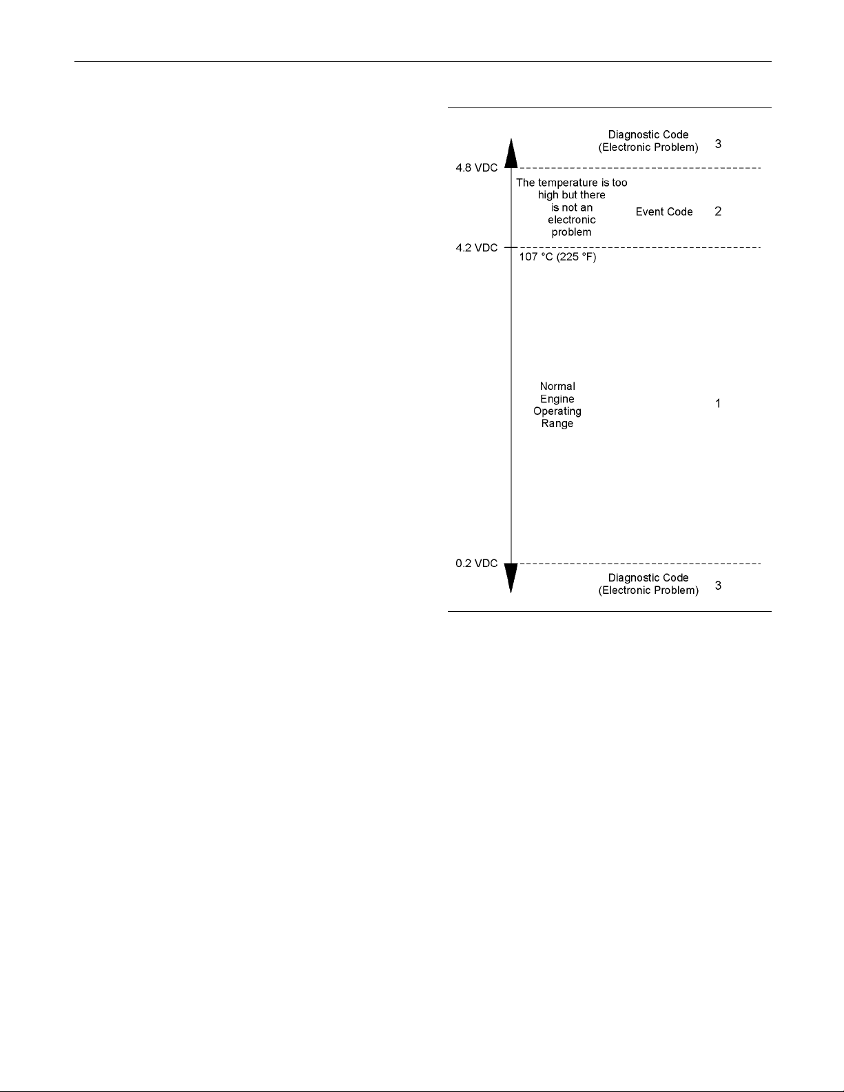
RENR5042-02 75
Troubleshooting Section
Troubleshooti
ng with an
Event Code
i02290980
Event C odes
SMCS Code: 190
Event codes alert the operator that an abnormal
engine operat
high coolant temperature has been detected. When
the event code is generated, the event is active.
Active Event Codes
An active event code represents a problem with
engine operation. Correct the problem as soon as
possible.
Active event codes are listed in ascending numerical
order. The c
Illustration 11 is an example of the operating range of
a temperatu
troubleshoot temperature sensors.
1
ing condition such as low oil pressure or
ode with the lowest number is listed first.
re sensor. Do not use the Illustration to
Illustration 11
Example of the typical operating range of a temperature sensor
(1) This area represents the normal operating range of the
parameter. The normal output voltage of the s ensor is b etween
0.2 V DC and 4.2 VDC.
(2) In this area, the temperature above 107 °C (22 5 °F) is higher
than normal. The output voltage of the sensor will generate an
event code. The sensor does not have an electronic problem.
(3) In these areas, the output voltage of the sensor is too high
or too low. T he voltage is outside of the normal range. The
electronic problem will generate a diagnostic code. Refer to
Troubleshooting, “Troubleshooting with a Diagnostic Code” for
additional information on diagnostic codes.
Events are represented in two formats. In the first
format, the “E” means that the code is an event
code. The “XXX” represents a numeric identifier for
the event code. This is followed by a description of
the code. If a warning, a derate, or a shutdown is
applicable, the numeric identifiers are different. Refer
to the following example:
E004 Engine Overspeed Shutdown
•
In the second format, the “E” means that the code is
an event code. The “XXX-X” represents a numeric
identifier for the event code. The fourth “X” identifies
the event as a warning, a derate, or a shutdown. This
is followed by a description of the code. Refer to the
following example:
g01138880
Page 76

76 RENR5042-02
Troubleshooting Section
E360-1 Low Oil Pressure Warning
•
E360-2 Low Oil Pressure Derate
•
E360-3 Low Oil P
•
The definition for a warning, a derate, and a shutdown
are defined be
Warning – This condition represents a serious
problem with e
condition does not require a derate or a shutdown.
Derate – For th
engine’s power in order to help prevent possible
engine damage.
Shutdown – For this condition, the ECM shuts down
theengineinordertohelppreventpossibleengine
damage.
Logged Event
When the ECM generates an event code the ECM
logs the code
an internal diagnostic clock. The ECM will record
the following information when an event code is
generated:
ressure Shutdown
low:
ngine operation. However, this
is condition, the ECM reduces the
Codes
in permanent memory. The ECM has
Troubleshooti
For basic troubleshooting of the engine, perform the
following step
1. Obtain the following information about the
complaint:
Theeventandthetimeoftheevent
•
Determine the conditions for the event. The
•
conditions will include the engine rpm and the
load.
Determine if there are any systems that were
•
installed by t
could cause the event.
Determine wh
•
occurred.
2. Verify that t
engine operation. Verify that the complaint is not
due to error of the operator.
3. Narrow the probable cause. Consider the operator
information, the conditions of operation, and the
history of t
s in order to diagnose a malfunction:
he engine.
ng
he dealer or by the customer that
ether any additional events
he complaint is not due to normal
The hour of the first occurrence of the code
•
The hour of the last occurrence of the code
•
The number o
•
Logged events are listed in chronological order. The
most recent
This information can be helpful for troubleshooting
intermitt
used to review the performance of the engine.
ent problems. Logged codes can also be
f occurrences of the code
event code is listed first.
Clearing Event Co des
Acodeiscl
following conditions occur:
Thecodedo
•
A new code is logged and there are already ten
•
codes in me
cleared.
The servic
•
Always clear logged event codes after investigating
and corre
code.
eared from memory when one of the
es not recur for 100 hours.
mory. In this case, the oldest code is
e technician manually clears the code.
cting the problem which generated the
4. Perform a visual inspection. Inspect the following
items:
Fuel supply
•
Oil level
•
Oil supply
•
Wiring
•
Connectors
•
Be sure to ch
important for problems that are intermittent. Refer to
Troubleshooting, “Electrical Connectors - Inspect”.
If these steps do not resolve the problem, identify
the procedures in this manual that best describe the
event. Che
tests that are recommended.
eck the connectors. This is very
ck each probable cause according to the
Trip Points for the Monitoring
System
The monitoring system determines the level of action
that is ta
in response to a condition that can damage the
engine. When any of these conditions occur, the
appropri
ken by the Electronic Control Module (ECM)
ate event code will trip.
Page 77

RENR5042-02 77
Troubleshooting Section
Table 15 contains the conditions that are monitored
and the default
condition has an associated parameter. The settings
for each parameter can be viewed with the Caterpillar
Electronic Te
of the parameters may be adjustable with Cat ET .
trip points for each condition. Each
chnician (ET). The trip points for some
Page 78
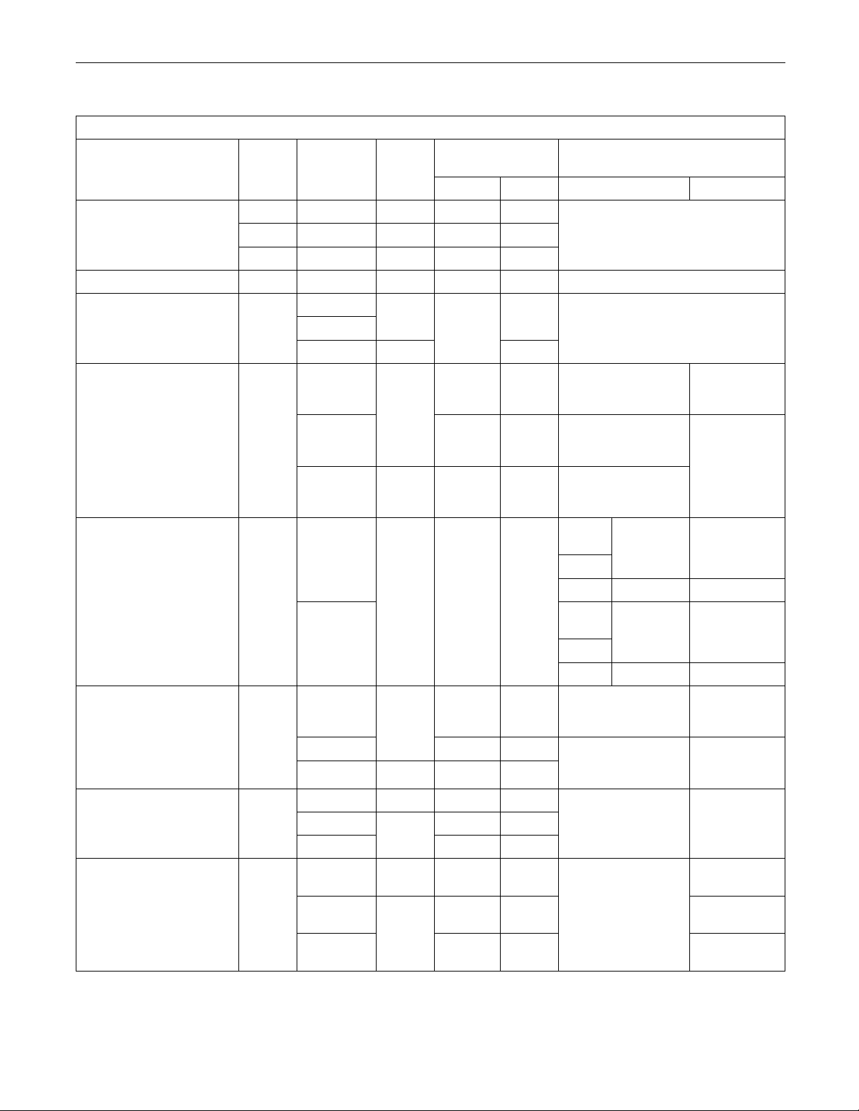
78 RENR5042-02
Troubleshooting Section
Table 15
Trip Points for the Monitoring System
Parameter
Event
Code
Action
E057 Derate On 1to54 10
Low Coolant Level
E058
Shutdown Off
E059 Warning
High Fuel Pressure E096 Warning
Warning
Low Engine Oil Pressure
E360
Derate
Shutdown Off
Warning None 10
High Engine Coolant
Temperature
E361
Derate
Shutdown Off 1to54 10
Warning
Engine Overspeed E362
Shutdown
Warning 1to54 30
High Fue
l Temperature
E363
Derate
Shutdown Off
Warning On 1to54 4
(2)
E443
Derate 1to54 3High Auxiliary Pressure
Shutdown
Warning
High Auxiliary
Temperature
(2)
E445
Derate 1to54 4
Shutdown
Default
Seconds
Value
Range Default Range Default
1to54 10
Time Delay in
On
On
1to54 10
None 8 Maps are not programmable.
On 8
None
On
1to54 10
On None 1
On
1to54 10
1to54 10
Off
1to54 3
On
1to54 4
Off
1to54 4
Maps are not programmable.
4
85 °C (185 °F)
110°C(230°
86 °C (187 °F)
111 °C (232 °F)
87 °C (189 °F)
111 °C (232 °F)
C11/
C13
C15
C18
C11/
C13
C15
C18
70 °C (158 °F)
90 °C (194 °F)
71 °C (160 °F)
91 °C (196 °F)
0kPa(0psi)
3150 kPa (457 psi)
0°C(0
140 °C (284 °F)
Set Points
None
to
F)
110 ° C
(230 °F)
to
111 °C
(232 °F)
to
1800-2600 2600
1800-2500 2500
1800-2800 2800
1800-2700 2700
to
to
to
90 °C (194 °F)
91 °C (196 °F)
1500 kPa
(218 psi)
105 °C
(221 °F)
°F)
to
106 °C
(223 °
107 °C
(224 °F)
(continued)
(1)
(1)
F)
Page 79
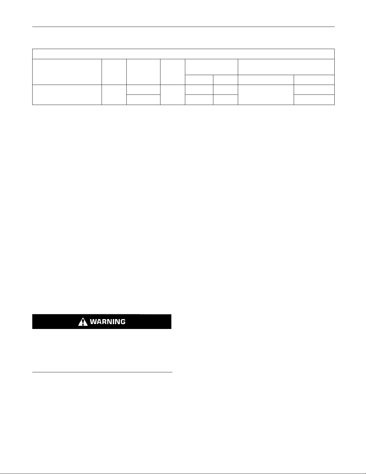
RENR5042-02 79
Troubleshooting Section
(Table 15, cont
High Engine Air Inlet
(1)
The maps may b e different. The maps d epend on the model of the engine.
(2)
The engine must be equipped with the appropriate sensor.
d)
Parameter
Temperature
Event
Code
E539
Trip Points for the Monitoring System
Action
Warning None 8
Derate
Default
Value
On
i02264589
E057 Low Engine Coolant
Level Derate
SMCS Code: 1395-038-LO
Conditions Which Generate This Code:
The coolant level is below the coolant level sensor.
System Response:
The ECM will log the event.
Possible P erformance Effect:
Engine power is reduced.
Troubleshooting:
The coolant level is most likely low.
•
There may be a problem with the coolant level
•
sensor.
Time Delay in
Seconds
Range
1to54 8
Default
Range
None
Set Points
Default
75 °C (167 °F)
79 °C (174 °F)
Results:
OK – The coolant level is low.
•
Repair: Check the cooling system for leaks. Repair
any problems that are found. Refill the cooling
system to the proper level.
STOP.
Not OK – The coolant level is not low.
•
Repair: There may be a problem with the coolant
level sensor. Refer to the diagnostic functional test
Troubleshooting, “Coolant Level Sensor Circuit Test” in order to verify that the coolant level sensor
is operating correctly.
Ensure that any repairs eliminate the problem.
STOP.
E058 Low Engine Coolant
i02274242
Check the Coolant Level
Pressurized System: Hot coolant can cause seri-
s burns. To open the cooling system filler cap,
ou
stop the engine and wait until the cooling system
components are cool. Loosen the cooling system
essure cap slowly in order to relieve the pres-
pr
sure.
op the engine.
A. St
B. After allowing the engine to cool, check the coolant
vel. Refer to the Operation and Maintenance
le
Manual for the proper procedure.
xpected Result:
E
The coolant level is low.
Level Shutdown
SMCS Code: 1395-038-LO
Conditions Which Ge n erate This Code:
The Electronic Control Module (ECM) detects a
problem with the engine’s cooling system. Information
on default settings and ranges for this event code
can be found in Troubleshooting, “Event Codes”.
System Response:
The event code will be logged.
Possible Performance Effect:
E058 (Shutdown)
The engine will shut down.
Troubleshooting:
The coolant level is most likely low.
•
Page 80
80 RENR5042-02
Troubleshooting Section
There may be a problem with the coolant level
•
sensor.
Check the Coolant Level
Pressurized System: Hot coolant can cause serious burns. To open the cooling system f iller cap ,
stop the engine and wait until the cooling system
components are cool. Loosen the cooling system
pressure cap slowly in order to relieve the pressure.
A. Stop the engine.
B. After allowing the engine to cool, check the coolant
level. Refer to the Operation and Maintenance
Manual for the proper procedure.
Expected Result:
The coolant level is low.
Results:
OK – The coolant level is low.
•
System Response:
The event code will be logged.
Possible Perfo
E057 (Warning)
None
Troubleshoot
The coolant level is most likely low.
•
There may be a problem with the coolant level
•
sensor.
rmance Effect:
ing:
Check the Coolant Level
Pressurized System: Hot coolant can cause serious burns. To open the cooling system filler cap,
stop the engine and wait until the cooling system
components are cool. Loosen the cooling sy stem
pressure cap slowly in order to relieve the pressure.
Repair: Check the cooling system for leaks. Repair
any problems that are found. Refill the cooling
system to the proper level.
STOP.
Not OK – The coolant level is not low.
•
Repair: There may be a problem with the coolant
level sensor. Refer to the diagnostic functional test
Troubleshooting, “Coolant Level Sensor Circuit Test” in order to verify that the coolant level sensor
is operating correctly.
Ensure that any repairs eliminate the problem.
STOP.
i02274243
E059 Low Engine Coolant
Level Warning
SMCS Code: 1395-038-LO
Conditions Which Generate This Code:
A. Stop the engine.
B. After allowing the engine to cool, check the coolant
level. Refer to the Operation and Maintenance
Manual for the proper procedure.
Expected Result:
The coolant level is low.
Results:
OK – The coolant level is low.
•
Repair: Check the cooling system for leaks. Repair
any problems that are found. Refill the cooling
system to the proper level.
STOP.
Not OK – The coolant level is not low.
•
Repair: There may be a problem with the coolant
level sensor. Refer to the diagnostic functional test
Troubleshooting, “Coolant Level Sensor Circuit Test” in order to verify that the coolant level sensor
is operating correctly.
The Electronic Control Module (ECM) detects a
problem with the engine’s cooling system. Information
on default settings and ranges for this event code
can be found in Troubleshooting, “Event Codes”.
Ensure that any repairs eliminate the problem.
STOP.
Page 81

RENR5042-02 81
Troubleshooting Section
i02277367
E096 High Fuel Pressure
SMCS Code: 1250
Conditions Which Generate This Code:
The Electronic Control Module (ECM) detects a
problem with the engine’s fuel pressure. Information
on default set
can be found in Troubleshooting, “Event Codes”.
System Respon
The event code will be logged.
Possible P erformance Effect:
E096 (Warning
None
Check the Fuel System
A. Verify that th
operating correctly. Check for damage or for dirt
in the check valve.
B. Check the return line from the check valve to the
fuel tank for damage or collapse.
Results:
-038-HQ
tings and ranges for this event code
se:
)
e check valve in the fuel manifold is
E360-2 (Derate)
The engine power will be derated.
E360-3 (Shutdo
The engine will shut down.
Troubleshooting:
There may be a p
system.
Check the Engi
A. Check the engine oil level. If the oil level is below
the oil pump’s
have the ability to supply enough lubrication to
the engine components. If the engine oil level is
low, add engin
engine oil level.
B. Check the fol
the engine oil pump:
a. Air leakage i
will also cause cavitation and loss of oil
pressure. Check the supply side of the oil pump
and make nec
b. Oil pump gears that have too much wear will
causearedu
engine oil pump.
wn)
roblem with the engine’s lubrication
ne’s Lubrication System
supply tube, the oil pump will not
e oil in order to obtain the correct
lowing problems that may occur to
n the supply side of the oil pump
essary repairs.
ction in oil pressure. Repair the
OK – A problem
•
valve or in the return line to the fuel tank.
Repair: Repl
STOP.
was found in either the check
ace all suspect parts.
i02274316
E360 Low E ng ine Oil Pressure
SMCS Code: 1348-038-LP
Conditions W
The Electronic Control Module (ECM) detects a
problem wit
on default settings and ranges for this event can be
found in Troubleshooting, “Event Codes”.
System Response:
The event co
Possible P erformance Effect:
E360-1 (Warning)
None
hich Generate This Code:
h the engine’s oil pressure. Information
de will be logged.
c. If the engin
pump, the scavenge pump may not be
supplying oil to the main engine oil pump.
C. The inlet screen of the oil suction tube for the
engine oil pump can have a restriction. This
restricti
engine oil pressure. Check the inlet screen on
the oil pickup tube and remove any material that
may be rest
pressure may also be the result of the oil pickup
tube that is drawing in air. Check the joints of the
oil picku
seal.
D. If the eng
open position, a reduction in the oil pressure can
be the result. This may be due to debris in the
engine o
stuck in the open position, remove each engine
oil bypass valve and clean each bypass valve in
order to
each bypass valve bore.
E. Engine o
will cause low engine oil pressure. High engine
oil level in the crankcase can be an indication of
contam
on will cause cavitation and a loss of
ination.
e is equipped with a scavenge
ricting engine oil flow. Low engine oil
p tube for cracks or a damaged O-ring
ine oil bypass valves are held in the
il. If the engine oil bypass valves are
correct this problem. You must also clean
il that is contaminated with fuel or coolant
Page 82

82 RENR5042-02
Troubleshooting Section
F. Excessive clearance at engine bearings will
cause low engin
components for excessive bearing clearance.
G. An oil line tha
will cause low engine oil pressure.
Expected Resu
An inspection of the engine’s lubrication system
indicated a pr
Results:
OK – There is a problem in the engine’s lubrication
•
system.
Repair: Repair the problem. Ensure that the repair
eliminates the problem.
STOP.
e oil pressure. Check the engine
t is open, broken, or disconnected
lt:
oblem.
i02274479
E361 High Engine Coolant
Temperature
Check the Engine’s Cooling System
A. Verify that the cooling system is filled to the proper
level. If the coolant level is too low, air will get into
thecoolingsy
cause a reduction in coolant flow.
B. Check the radi
restriction to coolant flow.
a. Check for debr
of the radiator core. Debris between the fins of
the radiator core restricts air flow through the
radiator cor
b. Check internally for debris, dirt, or deposits on
the radiator
restrict the flow of coolant through the radiator.
C. Check the mix
sure that the recommendations in the Operation
and Maintenance Manual are followed.
D. Check the water temperature regulator. A water
temperature regulator that does not open, or a
water tempe
of the way can cause overheating.
stem. Air in the cooling system will
ator or the heat exchanger for a
is or damage between the fins
e.
core. Debris, dirt, or deposits will
ture of antifreeze and water. Make
rature regulator that only opens part
SMCS Code: 1395-038-TA
Conditions W
The Electronic Control Module (ECM) detects a
problem with
on default settings and ranges for this event can be
found in Troubleshooting, “Event Codes”.
System Response:
The event co
Possible P erformance Effect:
E361-1 (Warning)
None
E361-2 (Derate)
The engine power will be derated.
E361-3 (Shu
The engine will shut down.
Troubleshooting:
There may be
system.
hich Generate This Code:
the engine’s cooling system. Information
de will be logged.
tdown)
a problem with the engine’s cooling
E. Check the wa
damaged impeller does not pump enough coolant.
Remove the water pump and check for damage
to the impe
F. If the cooling system for this application is
equipped w
fan. A fan that is not turning at the correct speed
can cause improper air speed across the radiator
core. The
radiator core can cause the coolant not to cool to
the proper temperature differential.
G. Check for air in the cooling system. Air can enter
the cooling system in d ifferent ways. The most
common c
the incorrect filling of the cooling system and
combustion gas leakage into the cooling system.
Combust
inside cracks, a damaged cylinder head, or a
damaged cylinder head gasket.
H. Check the cooling system hoses and clamps.
Damaged hoses with leaks can normally be seen.
Hoses t
operation. The soft areas of the hose can become
kinked or crushed during operation. These areas
of the h
become soft and/or get cracks after a period of
time. The inside of a hose can deteriorate, and the
particles of the hose can restrict the coolant
loose
flow.
ter pump. A water pump with a
ller.
ith a fan, check the operation of the
lack of proper air flow across the
auses of air in the cooling system are
ion gas can get into the system through
hat have no visual leaks can soften during
ose can restrict the coolant flow. Hoses
Page 83

RENR5042-02 83
Troubleshooting Section
I. If the cooling system for this application is
equipped with a
line for the expansion tank. The shunt line must be
submerged in the expansion tank. A restriction of
the shunt line
of the jacket water pump will cause a reduction in
water pump efficiency. A reduction in water pump
efficiency w
J. If the cooling system for this application
is equipped w
aftercooler. A restriction of air flow through the air
to air aftercooler can cause overheating. Check
for debris o
flow of air through the aftercooler.
K. Check for a r
restriction of the air that is coming into the engine
can cause high cylinder temperatures. High
cylinder te
temperatures in the cooling system.
L. Check for a
A restriction of the air that is coming out of the
engine can cause high cylinder temperatures.
M. Consider high ambient temperatures. When
ambient temperatures are too high for the rating
of the coo
temperature difference between the ambient air
and coolant temperatures.
N. Consider high altitude operation. The cooling
capability of the cooling system is reduced at
higher al
is large enough to keep the coolant from boiling
must be used.
titudes. A pressurized cooling system that
n expansion tank, check the shunt
from the expansion tank to the inlet
ill result in low coolant flow.
ith an aftercooler, check the
r deposits which would prevent the free
estriction in the air inlet system. A
mperatures cause higher than normal
restriction in the exhaust system.
ling system, there is not enough of a
E362 Engine Overspeed
SMCS Code: 7410
Conditions Which Ge n erate This Code:
The Electronic Control Module (ECM) detects
an overspeed condition. Information on default
settings and r
Troubleshooting, “Event Codes”.
System Respon
The event code will be logged.
Possible Performance Effect:
E362-1 (Warni
None
E362-2 (Derate)
None
E362-3 (Shutdown)
The engine will be shut down.
Troubleshoot
The operator may be operating the machine
incorrectly.
Talk to the Operator
-038; 7427-038
anges for this event can be found in
se:
ng)
ing:
i02291001
O. The engine may be running in the lug condition.
When the load that is applied to the engine is
too larg
When the engine is running in the lug condition,
engine rpm does not increase with an increase of
fuel. T
coolant flow through the system.
Expect
A thorough inspection of the cooling system revealed
aprobl
Results:
OK – There is a problem with the cooling system.
•
Repair
eliminates the problem.
STOP.
e, the engine will run in the lug condition.
his lower engine rpm causes a reduction in
ed Result:
em.
: Repair the problem. Ensure that the repair
Determine the events that caused the overspeed of
the engine.
Results:
OK – STOP.
•
i02291100
E363 High Fu e
SMCS Code: 1250-038-TA
Conditions Which Ge n erate This Code:
The temperat
point. Information on default settings and ranges for
this event code can be found in Troubleshooting,
“Event Code
System Response:
The event code is logged.
ure of the fuel has exceeded the trip
s”.
l Temperature
Page 84

84 RENR5042-02
Troubleshooting Section
Possible P erformance Effect:
E363-1 (Warning)
None
E363-2 (Derate)
The engine power is derated.
E363-3 (Shutd
Theengineisshutdown.
Troubleshooting:
Check the Fuel
Check the fuel system.
Expected Result:
A thorough ins
a problem.
Results:
own)
System
pection of the fuel system revealed
The Electronic Control Module (ECM) will derate
engine power.
443-3 (Shutdown)
The engine will shut down.
Troubleshoot
Use the Caterpillar Electronic Technician (ET) to view
the parameter
that the set points are valid for the application.
Determine the
Make corrections in order to prevent the high
pressure from recurring.
Results:
OK – STOP.
•
E445 High Aux
ing:
setting for auxiliary pressure. Verify
cause of the high pressure condition.
i02291151
iliary
Temperature
OK – There is a problem with the fuel system.
•
Repair: Make the necessary repairs. Verify that
the repair eliminates the problem.
STOP.
i02291109
E443 High Au xiliary Pressure
SMCS Code: 50
Conditions Which Generate This Code:
The pressure that is sensed by the auxiliary pressure
sensor has exceeded the trip point. Information on
default sett
found in Troubleshooting, “Event Codes”.
System Respo
The event code will be logged.
Possible P erformance Effect:
443-1 (Warni
None
443-2 (Derate)
95-038-AX
ings and ranges for this event can be
nse:
ng)
SMCS Code: 50
Conditions Which Ge n erate This Code:
The pressure that is sensed by the auxiliary
temperature sensor has exceeded the trip point.
Information
event can be found in Troubleshooting, “Event
Codes”.
System Response:
The event co
Possible Performance Effect:
443-1 (Warning)
None
443-2 (Derate)
The Electronic Control Module (ECM) will derate
engine power.
443-3 (Shutdown)
Theenginew
Troubleshooting:
Use the Caterpillar Electronic Technician (ET) to view
the parameter setting for auxiliary temperature. Verify
that the se
95-038-AX
on default settings and ranges for this
de will be logged.
ill shut down.
t points are valid for the application.
Page 85

RENR5042-02 85
Troubleshooting Section
Determine the cause of the high temperature
condition. Mak
high temperature from recurring.
Results:
OK – STOP.
•
e corrections in order to prevent the
i02286870
E539 High Intake Manifold Air
Temperature
SMCS Code: 1050-038-TA
Conditions Which Generate This Code:
The Electroni
a problem with the engine’s intake manifold air
temperature. Information on default settings and
ranges for th
“Event Codes”.
System Respo
The event code will be logged.
Possible P erformance Effect:
E539-1 (Warn
None
E539-2 (Derate)
c Control Module (ECM) detects
is event can be found in Troubleshooting,
nse:
ing)
b. Check the quality of the coolant. Follow
the recommenda
Maintenance Manual.
c. Check the radi
the inlet temperature of the coolant for the
radiator. Compare the reading to the regulated
temperature
the outlet temperature of the coolant. A high
temperature differential indicates an insufficient
flow rate.
d. Check for air in the cooling system. Air can
enter the coo
most common causes of air in the cooling
system are the incorrect filling of the cooling
system and c
cooling system. Combustion gas can get into
the system through inside cracks, a damaged
cylinder he
gasket.
e. Check the c
Damaged hoses with leaks can normally be
seen. Hoses that have no visual leaks can
soften dur
hose can become kinked or crushed during
operation. These areas of the hose can restrict
the coola
cracks after a period of time. The inside of a
hose can deteriorate, and the loose particles of
the hose c
f. If a sea water strainer is used in the application,
verify t
ing operation. The soft areas of the
nt flow. Hoses become soft and/or get
hat the sea water strainer is not plugged.
tions in the Operation and
ator for blockage. Check
. If the temperature is OK, check
ling system in different ways. The
ombustion gas leakage into the
ad, or a damaged cylinder head
ooling system hoses and clamps.
an restrict the coolant flow.
Theenginep
Troubleshooting:
Intake manifold air temperature can be high for the
following reasons:
Engine’s cooling system
•
High ambien
•
High inlet air restriction and/or high altitude
•
Restriction in the exhaust system
•
Faulty inle
•
ower will be derated.
t air temperature
t air temperature sensor and/or circuit
Perform the following Inspections
A. Check the Engine’s C ooling System.
a. Verify that
proper level. If the coolant level is too low,
air will get into the cooling system. Air in the
cooling sys
flow.
the cooling system is filled to the
tem will cause a reduction in coolant
g. Check the heat exchanger for a restriction to
the flow
h. Check the water pump. A water pump with
a damage
coolant. Remove the water pump and check for
damage to the impeller.
i. Check the water temperature regulator. A water
temperature regulator that does not open, or a
water t
part of the way can cause overheating.
j. If the c
equipped with an expansion tank, check the
shunt line for the expansion tank. The shunt
line m
tank. A restriction of the shunt line from the
expansion tank to the inlet of the jacket water
pump w
efficiency. A reduction in water pump efficiency
will result in low coolant flow.
of water.
d impeller does not pump enough
emperature regulator that only opens
ooling system for this application is
ust be submerged in the expansion
ill cause a reduction in water pump
Page 86

86 RENR5042-02
Troubleshooting Section
k. If the cooling system for this application
is equipped wit
aftercooler. A restriction of air flow through the
air to air aftercooler can cause overheating.
Check for debr
prevent the free flow of air through the
aftercooler.
l.
m. Theenginema
When the load that is applied to the engine
is too large, the engine will run in the lug
condition. W
lug condition, engine rpm does not increase
with an increase of fuel. This lower engine rpm
causes a red
system.
B. Check for Hi
a. Determine if the ambient air temperature
is within t
cooling system. When ambient temperatures
are too high for the rating of the cooling
system, th
difference between the ambient air and coolant
temperatures.
h an aftercooler, check the
is or deposits which would
y be running in the lug condition.
hen the engine is running in the
uction in coolant flow through the
gh Ambient Air Temperature
he design specifications for the
ere is not enough of a temperature
e. Consider high altitude operation. The cooling
capability of t
higher altitudes. A pressurized cooling system
that is large enough to keep the coolant from
boiling must b
settings for the engine are correct for the
altitude.
D. Check the Engine’s Exhaust System.
Check for a re
A restriction of the air that is coming out of the
engine can cause high cylinder temperatures.
Expected Result:
A thorough in
Results:
Yes – A thorough inspection revealed a problem.
•
Repair: Repa
eliminates the problem.
STOP.
he cooling system is reduced at
e used. Make sure that the
striction in the exhaust system.
spection revealed a problem.
ir the problem. Ensure that the repair
b. Determine the cause of the high air
temperature. Make corrections, when possible.
C. Check for High Inlet Air Restriction and/or
High Altitude
a. When inlet air pressure is low, the turbocharger
works harder in order to achieve the desired
inlet man
temperature.
b. Measure t
is operating under load. For specific data, refer
to the Technical Marketing Information for the
engine.
c. Check for plugged air filters. Check for
obstruc
air that is coming into the engine can cause
high cylinder temperatures. High cylinder
tempera
temperatures in the cooling system.
d. Replac
obstruction from the air inlet.
ifold pressure. This increases inlet air
he inlet air pressure while the engine
tions to the air inlet. A restriction of the
tures cause higher than normal
e the air filters and/or remove the
Page 87

RENR5042-02 87
Troubleshooting Section
Diagnostic Fun
ctional
Tests
i02289813
5 Volt Engine Pressure Senso r
SupplyCircuit-Test
SMCS Code: 5574-038
System Opera
The Electronic Control Module (ECM) creates a
regulated vo
to terminal A of the harness connectors for these
sensors:
Injection actuation pressure sensor
•
Boost pressu
•
Atmospheric pressure sensor
•
Fuel pressure sensor
•
tion Description:
ltage of 5.0 ± 0.2 VDC that is supplied
re sensor
Engine oil pr
•
Auxiliary pressure sensor (if equipped)
•
This procedure covers the following diagnostic codes:
262-03 5 Volt
•
+batt
262-04 5 Vol
•
ground
100-10 Engi
•
of change
102-10 Boos
•
change
A +5 V diagno
short circuit to ground or a short circuit to another
voltage source in the harness. The next likely cause
is a proble
a problem with the ECM.
essure sensor
Sensor DC Power Supply short to
t Sensor DC Power Supply short to
ne Oil Pressure Sensor abnormal rate
t Pressure Sensor abnormal rate of
stic code is probably caused by a
m with a sensor. The least likely cause is
Page 88
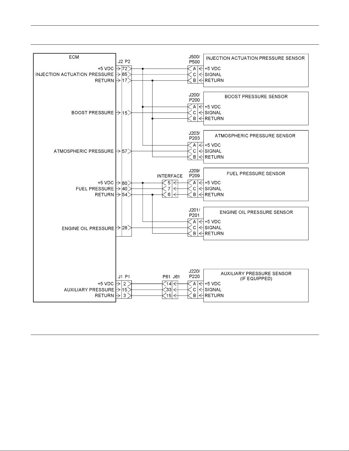
88 RENR5042-02
Troubleshooting Section
Illustration 12
Schematic for the 5 volt supply
Test Step 1. Inspec t the Electrical
Connectors and the Wiring
A. Turn the keyswitch to the OFF position.
g01119880
Page 89
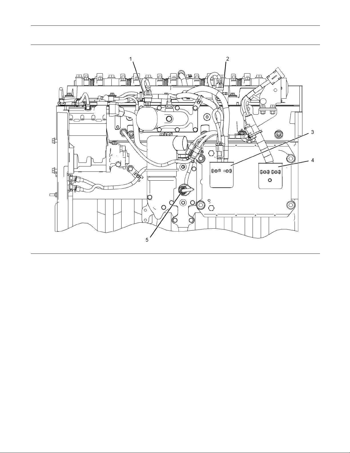
RENR5042-02 89
Troubleshooting Section
Illustration 13
Left side view
(1) Boost pressure sensor
(2) Atmospheric pressure sensor
(3) J2/P2 con nectors
(4) J1/P1 con nectors
(5) Engine oil pressure sensor
g01121143
Page 90
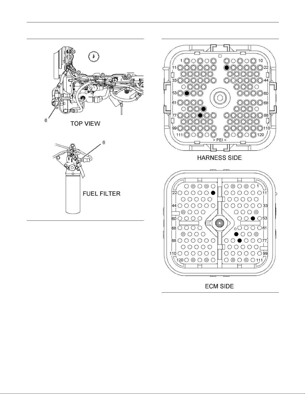
90 RENR5042-02
Troubleshooting Section
Illustration 14
The location of the fuel pressure sensor depends on the engine’s
configuration.
(6) F uel pressure sensor
g01121144
B. Thoroughly inspect connectors (3) and (4).
Thoroughly inspect the connectors for each
pressure sensor. Refer to Troubleshooting,
“Electrical Connectors - Inspect”.
Illustration 15
P2 terminals tha t are associated with the 5 volt supply for the
pressure sensors
(P2-17) Return
(P2-54) Return
(P2-72) +5 VDC
(P2-80) +5 VDC
g01123205
Page 91
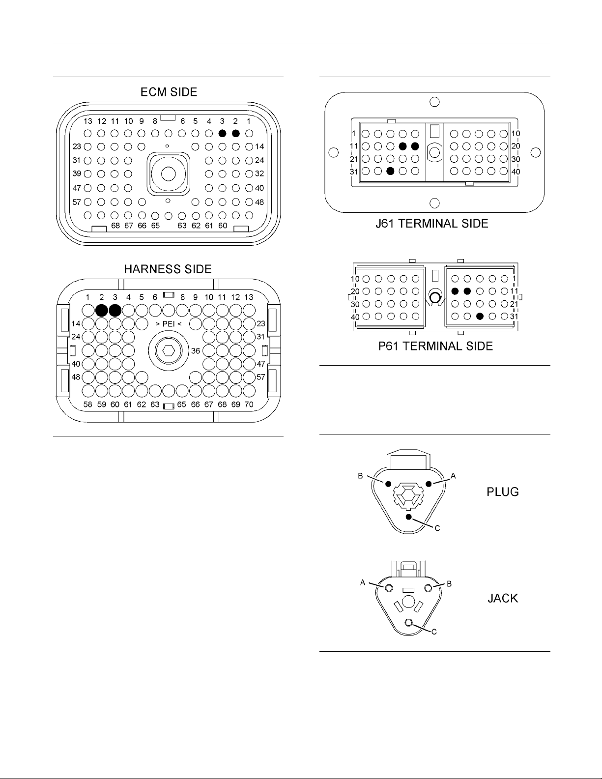
RENR5042-02 91
Troubleshooting Section
Illustration 16
P1 terminals that are ass ociated with the 5 volt supply for the
pressure sensors
(P1-2) +5 VDC
(P1-3) Return
g01123207
ion 17
Illustrat
J61/P61 terminals that are associated with the 5 volt s upply for the
pressure sensors
(14) +5 VDC
(15) Return
g01123208
Illustration 18
Connectors for the sensors
(A) Supply
(B) Return
(C) Signal
g01123211
C. Perform a 45 N (10 lb) pull test on each of the
wires that are associated with the pressure sensor
supply.
Page 92

92 RENR5042-02
Troubleshooting Section
D. Check the allen head screw on each ECM
connector for t
Troubleshooting, “Electrical Connectors - Inspect”
for the correct torque values.
E. Check the allen head screw on the customer
connector for the proper torque. Refer to
Troubleshoo
for the correct torque value.
F. Check the har
and for pinch points from each sensor back to the
ECM.
Expected Result:
All of t he con
coupled and/or inserted and the harness and wiring
are free of corrosion, of abrasion and of pinch points.
Results:
OK – The harn
•
OK. Proceed to Test Step 2.
Not OK – The c
•
OK.
Repair: Rep
Replace parts, if necessary. Ensure that all of the
seals are properly in place and ensure that the
connector
repair eliminates the problem.
he proper torque. Refer to
ting, “Electrical Connectors - Inspect”
ness and the wiring for abrasion
nectors, pins and sockets are completely
ess and connectors appear to be
onnectors and/or wiring are not
air the wiring and/or the connectors.
s are completely coupled. Verify that the
Results:
Active 03 code – An 03 diagnostic code is active.
•
ProceedtoTestStep3.
Active 04 code – An 04 diagnostic code is active.
•
ProceedtoTestStep5.
Active 10 code – A 10 diagnostic code is active.
•
ProceedtoTestStep4.
No active codes – None of the above codes are
•
active.
Repair: If any of the above codes are logged
and the engine is not running properly, refer to
Troubleshoo
Diagnostic Code”.
If the engine
may be an intermittent problem in a harness
that is causing the codes to be logged. Refer to
Troublesho
STOP.
ting, “Troubleshooting Without a
is running properly at this time, there
oting, “Electrical Connectors - Inspect”.
Test Step 3. Check the Voltage on the +5
V Supply Wire
A. Turn the key
B. Disconnect the harness connectors for the
following s
switch to the OFF position.
ensors:
STOP.
Test Step 2. Check for Active Diagnostic
Codes
A. Connect the Caterpillar Electronic Technician
(ET) to the service tool connector. Refer to
Troubles
B. Turn the keyswitch to the ON position.
C. Observe the “Active Diagnostic” screen on Cat ET.
Wait at least 15 seconds so that any codes may
become ac
•
•
•
•
Expected Result:
One of the
hooting, “Electronic Service Tools”.
tive. Look for these codes:
262-03
262-04
100-10
102-10
above codes is active.
Injection actuation pressure sensor J500/P500
•
Boost pressure sensor J200/P200
•
Atmospher
•
Fuel pressure sensor J209/P209
•
Engine oil pressure sensor J201/P201
•
Auxiliary
•
equipped)
C. Turn the ke
Note: Be sure to wiggle the harness during the
following
intermittent condition.
D. Measure th
at each sensor connector on the engine harness.
Expected
Each voltage measurement is 5.0 ± 0.2 VDC.
ic pressure sensor J203/P203
pressure sensor J220/P220 (if
yswitch to the ON position.
measurements in order to reveal an
e voltage between terminals A and B
Result:
Page 93

RENR5042-02 93
Troubleshooting Section
Results:
OK – Each voltage measurement is 5.0 ± 0.2 VDC.
•
Repair: Connec
Clear all diagnostic codes. Check for active
diagnostic codes. If the problem is intermittent,
refer to Troub
- Inspect”.
STOP.
Not OK – At least one voltage measurement is not
•
5.0 ± 0.2 VDC.
or with the ECM. Proceed to Test Step 6.
Test Step 4. C
V Supply Wire
A. Turn the keyswitch to the OFF position.
B. Disconnect the harness connectors for the
suspect sensor.
C. Turn the keyswitch to the ON position.
Note: Be sur
following measurement in order to reveal an
intermittent condition.
D. Measure the voltage between terminals A and B
on the harness connector for the suspect sensor.
t all of the sensor connectors.
leshooting, “Electrical Connectors
There is a problem with the wiring
heck the Voltage on the +5
for the Suspect Sensor
e to wiggle the harness during the
Boost pressure sensor J200/P200
•
Atmospheric pressure sensor J203/P203
•
Fuel pressure s
•
Engine oil pressure sensor J201/P201
•
Auxiliary pressure sensor J220/P220 (if
•
equipped)
B. Wait for 15 seconds after you disconnect each
sensor. Look for the active 262-04 code to
deactivate.
Expected Result:
The 262-04 diagnostic code deactivates when a
particular sensor is disconnected.
Results:
OK – The 262-0
•
when a particular sensor is disconnected.
Repair: Conn
returns, replace the sensor.
Connect all o
problem is resolved.
STOP.
ensor J209/P209
4 diagnostic code deactivates
ect the suspect sensor. If the code
f the connectors. Verify that the
Expected Result:
The voltag
Results:
Yes – The voltage measurement is 5.0 ± 0.2
•
VDC. The 5 volt supply is present at the harness
connector
is an active 10 diagnostic code.
Repair: Re
Verify that the problem is resolved.
STOP.
No – The vol
•
VDC. The 5 volt supply is not present at the
harness connector. There is a problem with the
wiring or
e measurement is 5.0 ± 0.2 VDC.
for the suspect sensor. However, there
place the suspect sensor.
tage measurement is not 5.0 ± 0.2
with the ECM. Proceed to Test Step 6.
Te st Step 5. Disconnect the +5 V Pressure
Sensors and C heck for Active Diagnostic
Codes
A. Disconnect the following sensors one at a time:
on actuation pressure sensor J500/P500
Injecti
•
Not OK – The 262-04 diagnostic code remains
•
after all of t
the sensors disconnected. Proceed to Test Step 6.
Test Step 6.
for a Short t
he sensors are disconnected. Leave
Check the +5 V Supply Wire
o Engine Ground or a Short
Circuit
A. Turn the keyswitch to the OFF position.
B. Disconnect the J2/P2 ECM connector. Disconnect
the J1/P1 ECM connector.
C. Verify that all of the pressure sensors are
disconnected.
Note: Wiggle the harness during the following
measurements in order to reveal an intermittent
conditio
D. Measure the resistance between terminal P2-72
E. Measure t
F. Measure t
n.
(+5 V Supp
P2 connector.
and the engine ground.
(+5 V Supply) and all of the other terminals on the
P2 connector.
ly) and all of the other terminals on the
he resistance between terminal P2-72
he resistance between terminal P2-80
Page 94

94 RENR5042-02
Troubleshooting Section
G. Measure the resistance between terminal P2-80
and the engine g
H. Measure the resistance between terminal P1-2
(+5 V Supply) a
on the P1 connector.
a. Measure the re
and the engine ground.
Expected Resu
Each resistance measurement indicates an open
circuit.
Results:
OK – Each resistance measurement indicates an
•
open circuit. Proceed to Test Step 7.
Not OK – At least one of the resistance
•
measurements does not indicate an open circuit. A
+5 V supply wi
problem with a connector.
Repair: Rep
when possible. Replace parts, if necessary. Verify
that the problem is resolved.
round.
nd all of the remaining terminals
sistance between terminal P1-2
lt:
re has a problem. There may be a
air the wire and/or the connector,
Repair: Repair the wire and/or the connector,
when possible.
that the problem is resolved.
STOP.
Replace parts, if necessary. Verify
Test Step 8. Check the +5 V Supply at the
ECM
A. Remove terminal 72 (+5 V Supply) from the
P2 connector. Install a wire jumper with socket
terminals on
B. Connect ECM connectors J2/P2.
C. Remove terminal 2 (+5 V Supply) from the P1
connector. Install a wire jumper with socket
terminals on
D. Connect ECM connectors J1/P1.
E. Turn the keyswitch to the ON position.
F. Measure the
P1-2 and the engine ground.
G. Measure the
P2-2 and the engine ground.
both ends into P2-72.
both ends into P1-2.
voltage between the wire jumper in
voltage between the wire jumper in
STOP.
Test Step 7.
the Sensor C
A. Install a wire jumper between terminals P2-72 (+5
V Supply) a
B. Install a wire jumper between terminals P1-2 (+5
V Supply) a
Note: Wiggle the harness during the following
measureme
short condition.
C. Measure th
B at the harness connector for each pressure
sensor.
Expected Result:
Each resi
Results:
OK – Each measurement is less than ten Ohms.
•
Proceed to Test Step 8.
Check the +5 V Supply and
ommon for an Open Circuit
nd P2-3 (Sensor Common).
nd P1-3 (Sensor Common).
nts in order to reveal any intermittent
e resistance between terminals A and
stance measurement is less than ten Ohms.
H. Turn the key
I. Restore both wires to the original configuration.
Expected Result:
Both voltag
Results:
OK – Both voltage measurements are 5.0 ± 0.2
•
VDC.
Repair: Clear all diagnostic codes. Check for active
diagnostic codes. If the problem is intermittent,
refer to Tr
- Inspect”.
STOP.
Not OK – At least one voltage measurement is
•
not 5.0 ± 0.
Repair: Replace the ECM. Refer to
Troublesh
STOP.
switch to the OFF position.
e measurements are 5.0 ± 0.2 VDC.
oubleshooting, “Electrical Connectors
2 VDC.
ooting, “Replacing the ECM”.
Not OK – At least one resistance measurement is
•
greater than ten Ohms. The +5 V supply wire or
the retur
may be a problem in a connector.
n wire has excessive resistance. There
Page 95
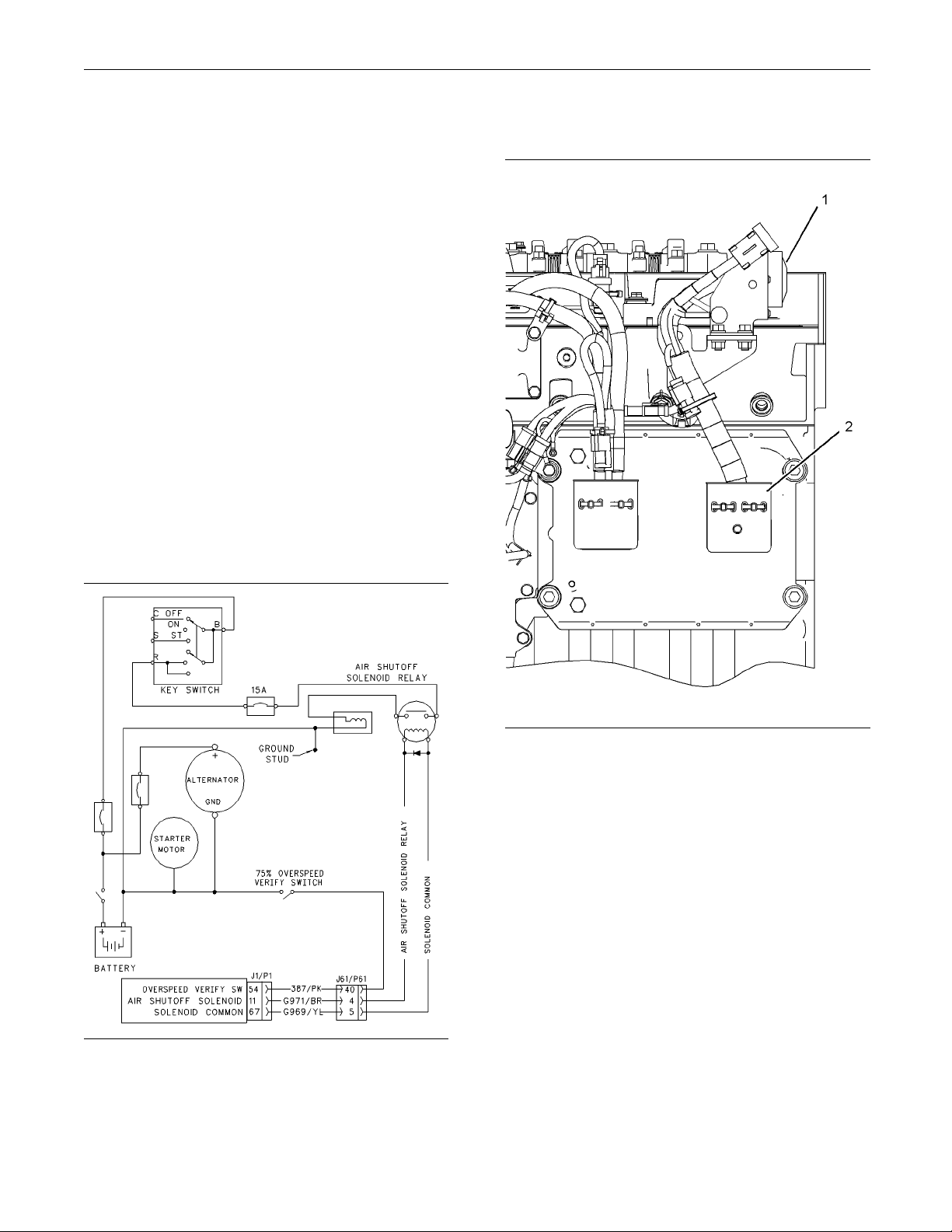
RENR5042-02 95
Troubleshooting Section
i02289818
Air Shuto ff System - Test
SMCS Code: 1078
System Operation Description:
The Electronic Control Module (ECM) has the ability
to stop the engine by shutting off the inlet air supply
in an emergenc
relay which energizes the air shutoff solenoid. The
solenoid trips the air shutoff valve.
There are two conditions which can cause the ECM
to activate the air shutoff relay. The first condition
occurs when t
The relay will be energized until the ECM detects
an engine speed of 0 rpm. The second condition
occurs when a
Theoverspeedverifyswitchisactivated.Whenthe
engine speed reaches 75 percent of the programmed
overspeed s
etpoint, the ECM will activate the air
shutoff relay. Again, this is used for testing purposes.
The air shut
off valve must be manually reset to the
OPEN position.
-038
y situation. The ECM activates a
he ECM detects an engine overspeed.
test of the air shutoff relay is made.
B. Verify that the air shutoff valves are set to the
Open position.
Illustration 19
Schematic for the air shutoff s ystem
Test Step 1. Inspec t the Electrical
Connectors and the Wiring
A. Turn the keyswitch to the OFF position.
g00743757
Illustration 20
Left side view
(1) P61 customer connector
(2) J1/P1 EC M c onnectors
g01121151
C. Thoroughly inspect connectors (1) and (2). Refer
to Troubleshooting, “Electrical Connectors Inspect”.
Page 96
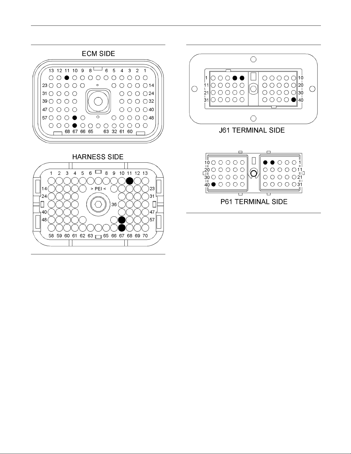
96 RENR5042-02
Troubleshooting Section
Illustration 21
P1 terminals that are associated with the air shutoff system
(P1-11) Air shutoff solenoid
(P1-54) O verspeed verify switch
(P1-67) Solenoid common
g01102047
ion 22
Illustrat
J61/P61 terminals that are associated with the air shutoff system
(4) Air s hutoff solenoid
(5) Solenoid common
(40) Ov erspeed verify switch
D. Perform a 4
5 N (10 lb) pull test on each of the
g01123348
wires that are associated with the circuit for the
air shutoff system.
E. Check the allen head screw on each ECM
connector for the proper torque. Refer to
Troubles
hooting, “Electrical Connectors - Inspect”
for the correct torque values.
F. Check the
allen head screw on the customer
connector for the proper torque. Refer to
Troubleshooting, “Electrical Connectors - Inspect”
for the co
rrect torque value.
G. Check the harness and the wiring for abrasion
and for pi
nch points from the air shutoff solenoid
to the ECM.
Expecte
dResult:
All connectors, pins, and sockets are completely
coupled
and/or inserted, and the harness and wiring
are free of corrosion, of abrasion and of pinch points.
Page 97

RENR5042-02 97
Troubleshooting Section
Results:
OK – The connectors and wiring are OK. Proceed
•
to Test Step 2.
Not OK – The connectors and/or wiring are not
•
OK.
Repair: Repair the wiring and/or the connectors.
Replace parts, if necessary. Ensure that all of
the seals are p
problem is resolved.
STOP.
roperly connected. Verify that the
Test Step 2. Test for Voltage from the
Normally Open Contacts of the Air
Shutoff Relay
A. Turn the keyswitch to the OFF position.
B. Remove the w
of the air shutoff relay that goes to the air shutoff
solenoid.
C. Connect a test lamp between the normally open
contact of the air shutoff relay and engine ground.
ire from the normally open contacts
C. Connect a test lamp between the wire from the
normally open c
engine ground.
D. Start the engi
E. Activate the overspeed verify switch.
F. Monitor the test lamp while you increase the
engine speed past 75 percent of the programmed
overspeed set
Expected Result:
The test lamp illuminated when the engine speed
increased past 75 percent of the programmed
overspeed se
Results:
OK – The test lamp illuminated. The voltage is
•
present at the air shutoff solenoid.
Repair: Verify the continuity of the wire from the
air shutoff solenoid to the negative battery before
proceeding
that the problem is resolved.
ontact of the air shutoff relay and
ne.
point.
tpoint.
. Replace the air shutoff solenoid. Verify
D. Start the engine.
E. Activate t
F. Monitor the test lamp while you increase the
engine spe
overspeed setpoint.
G. Turn the ke
H. Disconnect the test lamp’s leads. Connect the
wire to the
Expected Result:
The test lamp illuminated when the engine speed
increased past 75 percent of the programmed
overspee
Results:
OK – The test lamp illuminated. The air shutoff
•
relay is operating correctly. Proceed to Test Step 3.
Not OK – The test lamp did not illuminate. Proceed
•
to Test Step 4.
he overspeed verify switch.
ed past 75 percent of the programmed
yswitchtotheOFFposition.
normally open contact.
d setpoint.
Test Step 3. Test for Voltage at the Air
Shutoff Solenoid
STOP.
Not OK – The test lamp did not illuminate. System
•
voltage was
There is a problem in the wiring between the air
shutoff solenoid and the air shutoff relay. There
maybeaprob
Repair: Repair the wiring and/or the connector.
Replace pa
is resolved.
STOP.
not present at the air shutoff solenoid.
lem with a connector.
rts, if necessary. Verify that the problem
Test Step 4. Test for Voltage at the Coil of
the Air Shutoff Relay
A. Turn the keyswitch to the OFF position.
B. Disconnec
from the ECM to the air shutoff relay. Disconnect
the wire at the coil of the air shutoff relay.
C. Connect the test lamp between the end of the wire
and engine ground.
D. Start the engine.
E. Activate
t the wire that carries the drive signal
the overspeed verify switch.
A. Turn the
B. Disconnect the wires that are connected to the
coil of t
keyswitch to the OFF position.
he air shutoff solenoid.
F. Monitor the test lamp while you increase the
engine sp
overspeed setpoint.
eed past 75 percent of the programmed
Page 98
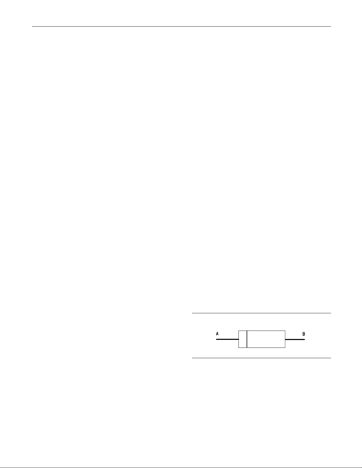
98 RENR5042-02
Troubleshooting Section
Expected Result:
The test lamp illuminated when the engine speed
increased past 75 percent of the programmed
overspeed set
Results:
OK – The test lamp illuminated. Verify the
•
continuity of the wire from the coil of the air
shutoff relay
proceeding. Proceed to Test Step 6.
Not OK – The te
•
voltage from the ECM was not present at the coil
of the air shutoff relay. Proceed to Test Step 5.
point.
to the ECM connector P1-67 before
st lamp did not illuminate. The
Test Step 5. Short the Overspeed Verify
Switch at the ECM
A. Turn the keys
B. Disconnect ECM connector P1.
C. Remove terminal P1-54 (overspeed verify switch).
D. Insert one e
for P1-54 (overspeed verify swtich). Connect the
other end of the wire jumper to engine ground.
witchtotheOFFposition.
nd of a wire jumper into the socket
Repair: Verify the continuity of the wire for the
overspeed veri
Close the overspeed verify switch and measure
the continuity from P1-54 to the negative battery.
If the wire doe
negative battery, repair the wire and/or replace the
overspeed verify switch.
If the wire for the overspeed verify switch has
continuity to the negative battery, there is a
problem in th
shutoff relay. Repair the circuit connectors or wiring
and/or replace the circuit connectors or wiring.
Verify that
STOP.
Not OK – The test lamp did not illuminate.
•
Repair: Per
1. Remove all jumpers and reconnect all terminals.
2. Temporarily install a new ECM. Refer to
Troubleshooting, “Replacing the ECM”.
3. Check the system for active diagnostic codes.
4. Perform thi
fy switch to the negative battery.
s not have continuity to the
ewiringbetweenP1-11andtheair
the problem is resolved.
form the following procedure:
sTestStepagain.
E. Remove terminal P1-11 (air shutoff solenoid).
F. Insert one e
for P1-11 (air shutoff solenoid).
G. Connect on
of the jumper wire in P1-11 (air shutoff solenoid).
H. Connect th
battery.
I. Start the e
J. Activate the overspeed verify switch.
K. Monitor the test lamp while you increase the
engine speed past 75 percent of the programmed
overspeed
Expected Result:
The test lamp illuminated when the engine speed
increased past 75 percent of the programmed
overspee
Results:
OK – The test lamp illuminated.
•
nd of the wire jumper into the socket
e lead of the test lamp to the other end
e other lead of the test lamp to negative
ngine.
setpoint.
d setpoint.
5. If the problem is resolved with the test ECM,
reconnect t
problem returns. If the problem returns with the
suspect ECM, replace the ECM.
6. Verify that the problem is resolved.
STOP.
he suspect ECM. Verify that the
Test Step 6. Test the Diode for Current
Flow in One Direction
Illustration 23
Diode
A. Disconnect the wires from the air shutoff relay.
B. Remove the diode from the air shutoff relay.
C. Put the digital voltmeter (DVM) in “Diode Check”.
g00761537
Page 99

RENR5042-02 99
Troubleshooting Section
D. Refer to Illustration 23. Place the red lead of the
DVM on the diode
lead of the DVM on the diode at location (B).
E. Measure the vo
Expected Result:
The voltage drop across the diode is less than one
volt.
Results:
OK – The voltag
•
than one volt. Proceed to Test Step 7.
Not OK – The vol
•
greater than one volt.
Repair: Repla
is resolved.
STOP.
at location (A). Place the black
ltage drop across the diode.
e drop across the diode is less
tage drop across the diode is
ce the diode. Verify that the problem
Test Step 7. Test the Diode for Current
Flow in the Opposite Direction
A. Reverse the locations of the leads for the DVM.
B. Measure the v
oltage drop across the diode.
Expected Result:
The test lamp illuminates.
Results:
OK – The test lamp illuminated.
•
Repair: Replace the air shutoff relay. Verify that
the problem is resolved.
STOP.
Not OK – The tes
•
to Test Step 9.
Test Step 9. Ch
Keyswitch to
A. Turn the keyswitch to the OFF position.
B. Remove the wire from terminal R of the keyswitch.
C. Turn the keys
D. Measure the voltage between terminal B of the
keyswitch an
E. Measure the voltage between terminal R of the
keyswitch an
t lamp did not illuminate. Proceed
eck the Voltage from the
the Air Shutoff Relay
witch to the ON position.
d engine ground.
d engine ground.
Expected Result:
The voltage drop across the diode is an OL.
Results:
OK – The voltage drop across the diode is an OL.
•
Proceed to T
Not OK – The voltage drop across the diode is
•
less than on
Repair: Replace the diode. Verify that the problem
is resolved
STOP.
est Step 8.
evolt.
.
Test Step 8. Check the Voltage from
the Keyswitch to the Normally Open
Contacts of the Air Shutoff Relay
A. Turn the k
B. Disconnect the wire to the normally open contacts
of the air
C. Connectthetestlampbetweenthewireand
engine gr
D. Turn the keyswitch to the ON position.
eyswitch to the OFF position.
shutoff relay from the keyswitch.
ound.
F. Turn the keyswitch to the OFF position.
Expected Result:
Voltage is p
the keyswitch.
Results:
OK – Voltage is present on terminal B and terminal
•
R at the keys
Repair: If voltage is present on terminal R, repair
thewirebet
relay. Verify that the breaker is not tripped. Return
all wiring to the original configuration. Verify that
the problem
STOP.
Not OK – Voltage is not present on terminal B at
•
the keyswitch.
Repair: If voltage is not present on terminal
B, repair the wire between the +Battery and
the keyswi
tripped. Verify that the battery disconnect switch
is operating correctly. Check the battery’s
no-load v
configuration. Verify that the problem is eliminated.
resent on terminal B and terminal R at
witch.
ween the keyswitch and the air shutoff
is eliminated.
tch. Verify that the breaker is not
oltage. Return all wiring to the original
STOP.
Page 100
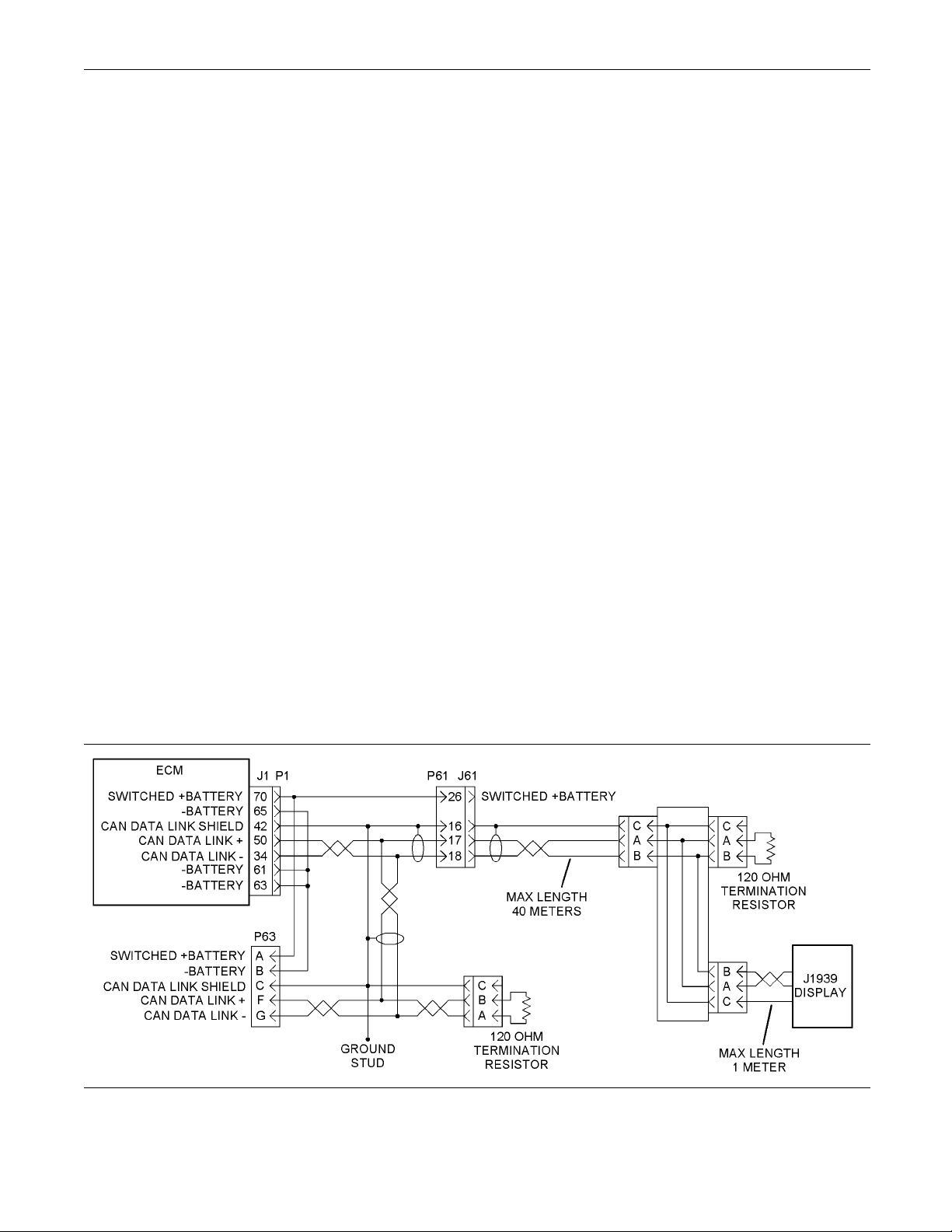
100 RENR5042-02
Troubleshooting Section
Not OK – Voltage is not present on terminal R at
•
the keyswitch.
Repair: If voltage is present on terminal B of the
keyswitch but
the keyswitch. Return all wiring to the original
configuration. Verify that the problem is eliminated.
STOP.
not present on terminal R, replace
i02289824
CAN Data Link Circuit - Test
SMCS Code: 190
System Operation Description:
The CAN data link is used to communicate
information between the Electronic Control Module
(ECM) and oth
troubleshoot any suspect problems with the CAN
data link.
This procedure covers the 247-09 diagnostic code.
This procedure identifies the following problems:
Faulty connectors
•
Missing ter
•
Short circuits
•
Open circuits
•
Faulty J193
•
1-038
er modules. Use this procedure to
mination resistors
9display
Illustration 24
Schematic for the CAN data link
g01119843
 Loading...