

Page 1
Special Instruction
REHS7414
18 January 2012
i04694729
Autonomous Stop (A-Stop)
System for Autonomous
Hauling
SMCS Code:
Off-Highway Truck/Tractor
793D (S/N: FDB1-Up)
793F (S/N: SSP1-Up; RBT1-Up)
797F (S/N: LAJ1-Up)
Table of C ontents
Introduction ........................................................... 1
Overview ............................................................... 1
A-Stop Operation .................................................. 3
Stopping ............................................................ 4
Clearing an A-Stop ............................................ 5
Resuming Autonomous Operation .................... 5
Testing the A-Stop System ................................... 5
Electrical Input Components ................................. 5
Autonomous Stop Receivers ............................. 5
Electrical Output Components .............................. 6
A-Stop Transmitter ............................................ 6
Note: Modifications not expressly approved by
the manufac
operate the equipment under FCC rules.
turer could void the user's authority to
Overview
Introduction
This document contains operational information
about the A-Stop System.
Note: This equipment has been tested and found to
comply with the limits for a Class A digital device,
pursuant to part 15 of the FCC rules. These limits
are designed to provide protection against harmful
interference when the equipment is operated in a
commercial environment. This equipment generates,
uses, and can radiate radio frequency energy and,
if not installed and used in accordance with the
instruction manual, may cause harmful interference
to radio communications. Operation of this equipment
in a residential area is likely to cause harmful
interference in which case the user will be required to
correct the interference at their own expense.
1
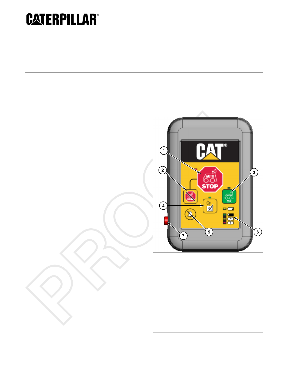
Illustration 1
e1
Tabl
Callout Button Description
Used to transmit
an A-Stop Signal
1
A-Stop Button
machines within
transmit until the
A-Stop Reset (2)
99169
g027
received by all
autonomous
range. The
A-Stop signal
will continue to
is pressed.
(1)
(continued)
Page 2
(Table 1, contd)
Callout
Button Description
Used to stop
transmitting the
A-Stop signal.
The A-Stop
Reset button
(2) will only stop
2
A-Stop Reset
Button
the transmission
of the A-Stop
signal, this
button will not
clear an effected
machine
to resume
operation.
Used to signal
all machines in
theareathat
those machines
can resume
autonomous
operation. Each
3 Clear Button
transmitter that
has signaled
an A-stop must
be pressed
before the
effect machine
can resume
operation.
Used to initiate
an A-Stop
system test
between the
transmitter and
4 Test Button
all autonomous
machines in
range of the
transmitter. The
test button (4) is
amomentary
switch
Used to silence
5
Alarm Silence
the audible
alarm during an
A-Stop event.
Used to show
6
Battery Charge
Indicators
status of the
transmitter
battery.
7 Charging Port
(1)
Only the transmitter that sent the A -Stop signal can cancel
the A-Stop command.
(2)
Pressing the c lear button (3) does not allow the truck to
resume the task it was assigned before the A-Stop was
initiated. The clear button (3) only allows the truck to receive
another assignment. MineStar must be used to assign an
autonomous ready truck after an A-Stop event.
Used to charge
the transmitter.
The autonomous stop (A-Stop) system is used to
stoptheautonomoustrucksintheareaincaseof
emergency or un
planned need. The system sends a
radio signal to all the trucks within the operating range
of the handheld transmitter. The communications of
the A-Stop sys
tem operate independently from the
normal autonomy system and can be used even if
MineStar cannot communicate with the truck.
Each person working in the area of autonomous
operation shall be issued an A-Stop transmitter and
is required t
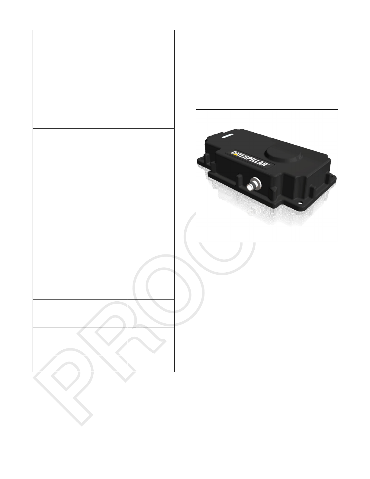
(2)
Illustration 2
Receiver
o carry the transmitter at all times.
g02799149
Each autonomous haul truck has two receivers which
operate on different data links. The receivers are
powered by the machine and send out a heartbeat
message to the truck under normal operation.
2
Page 3
A-Stop Operation
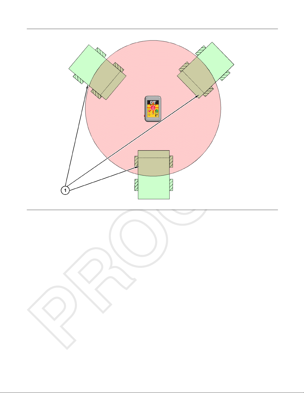
Illustration 3
Single transmitter in operation
(1) Autonomous machines with on-board
A-Stop receiver
Illustration 3 shows three Autonomous machines
with on-board A-Stop receivers. The flashing light
on the A-Stop remote indicates that an A-Stop has
been activated. The large circle in the illustration is
the range of the A-Stop remote. In the illustration,
the three Autonomous machines that are in range
of the A-Stop remote are stopped due to the A-Stop
button that was pressed.
g02728442
3
Page 4
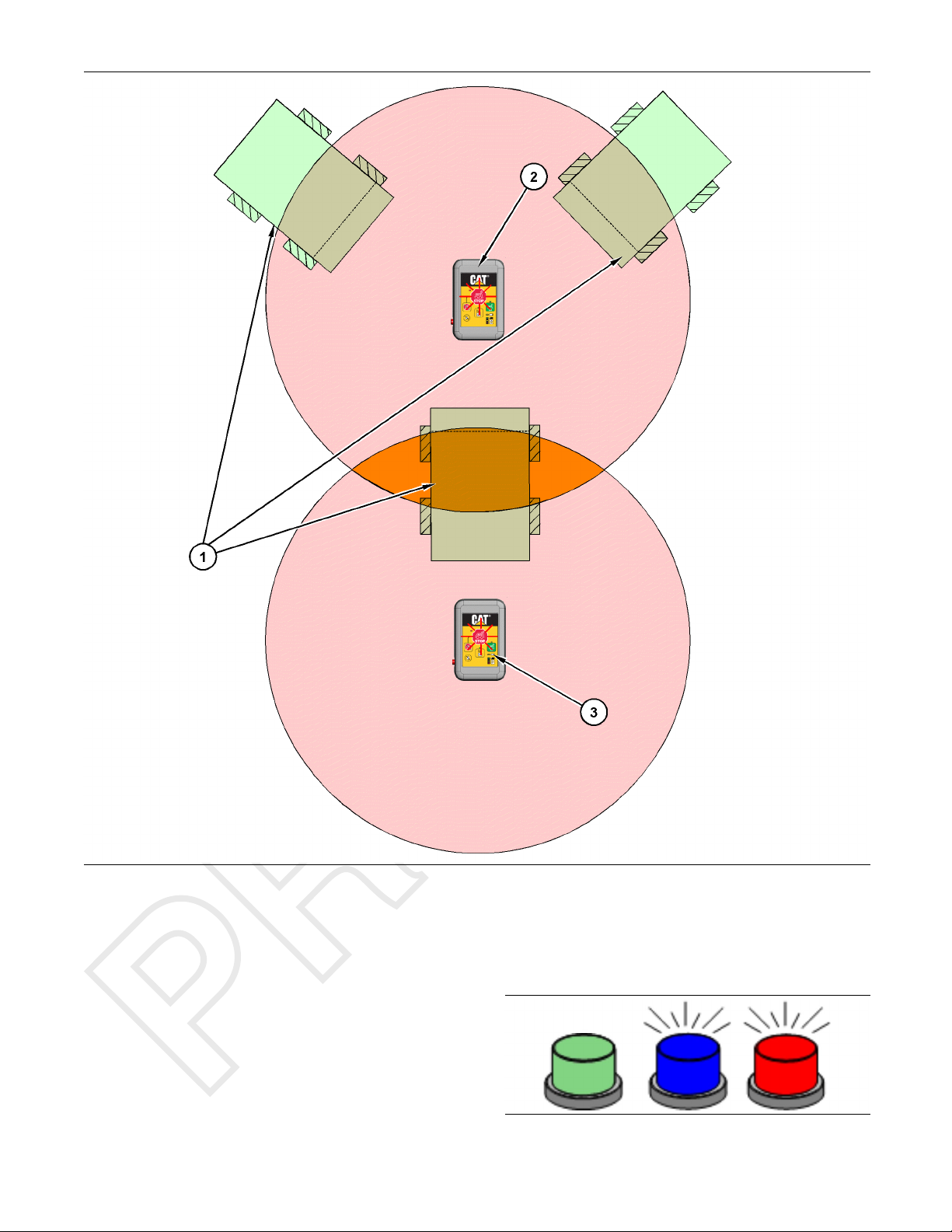
Illustration 4
Multiple transmitters in operation
(1) Autonomous machines with on-board
A-Stop receiver
g02727922
Once an A-Stop event has occurred, any machines
in the range of the remote transmitter will be stopped
for as long as the remote is transmitting. A “Clear”
signal will need to be sent before any of the machines
affected will be able to resume normal operation.
When more than one remote is activated at once, all
remotes that sent an A-Stop command will need to
send a “Clear” signal. Refer to Illustration 4 for an
example of multiple transmitters in operation at once.
Stopping
Illustration 5
4
g02742797
Page 5
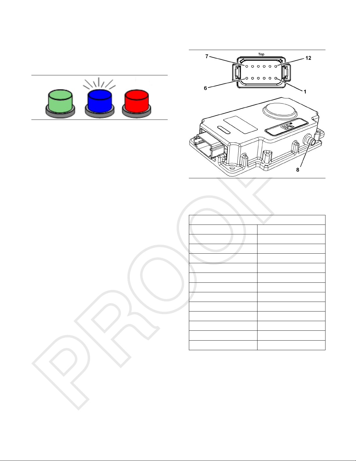
When a truck receives an A-Stop stop signal, the
truck immediately initiates a controlled stop. While
the truck is in a
utonomous mode with A-Stop active,
the autonomous mode and A-Stop lights will be
flashing. Refer to Illustration 5 for an example.
Clearing an A-Stop
Electrical Input Components
Autonomous Stop Receivers
Illustration 6
g02742856
The truck identifies and records which transmitter or
transmitters have initiated the A-Stop. The truck can
only resume autonomous operation when an A-Stop
clear message is received from all the transmitters
that the truck received a stop message from. Once
the truck has received a clear message from every
transmitter that the truck received a stop message
from, the truck will deactivate the A-Stop and the
A-Stop light with stop flashing. Refer to Illustration 6
for an example.
Resuming Autonomous Operation
When the truck has received all the necessary clear
messages, the truck is ready for a new assignment.
The truck will not automatically resume the task that
was assigned prior to the A-Stop. The truck requires
theMineStaroperatortoassignthetruckatask.
Testing the A-Stop System
An A-Stop transmitter can test the transmitter and
truck system by using the test button (4). Press and
hold the test button for 2 or more seconds while in
range of one or more autonomous trucks. The trucks
that receive the test message will acknowledge the
test by honking the truck horn.
The A-Stop system also has a self-test function.
The self-test is different from a test using an A-Stop
transmitter. Periodically, the truck will send out A-Stop
self-test signals that can detect a system failure all
the way down to the antenna. The truck will notify the
MineStar operator if a failure is detected in a self-test.
Illustration 7
A-Stop Receiver
(8) antenna connector
Table 2
Pin Location
1+Battery
2 - Battery
3
4
5
6
7
8CANHi
9CANLo
10 CAN Shield
11 NC
12 NC
g02799818
A-Stop Connector
Signal Identification
NC
NC
NC
NC
NC
5
Page 6
There are two A-Stop receivers per autonomous
truck. The receivers are powered from the machine
24V supply. The
MHz through the antenna which connects with a
cable to the antenna connector (8) located on the
side of the rec
with the autonomous machine using a CAN bus.
For redundancy, one receiver communicates
over the machi
communicates over the autonomous CAN circuit.
Under normal operation, the receivers transmit a
periodic hea
Stop (A-Stop) command from an A-Stop Transmitter
is received. The receivers also transmit to each other
for redunda
receivers send and transmit at 919
eiver. Each receiver communicates
ne CAN circuit and one receiver
rtbeat message until an Autonomous
ncy.
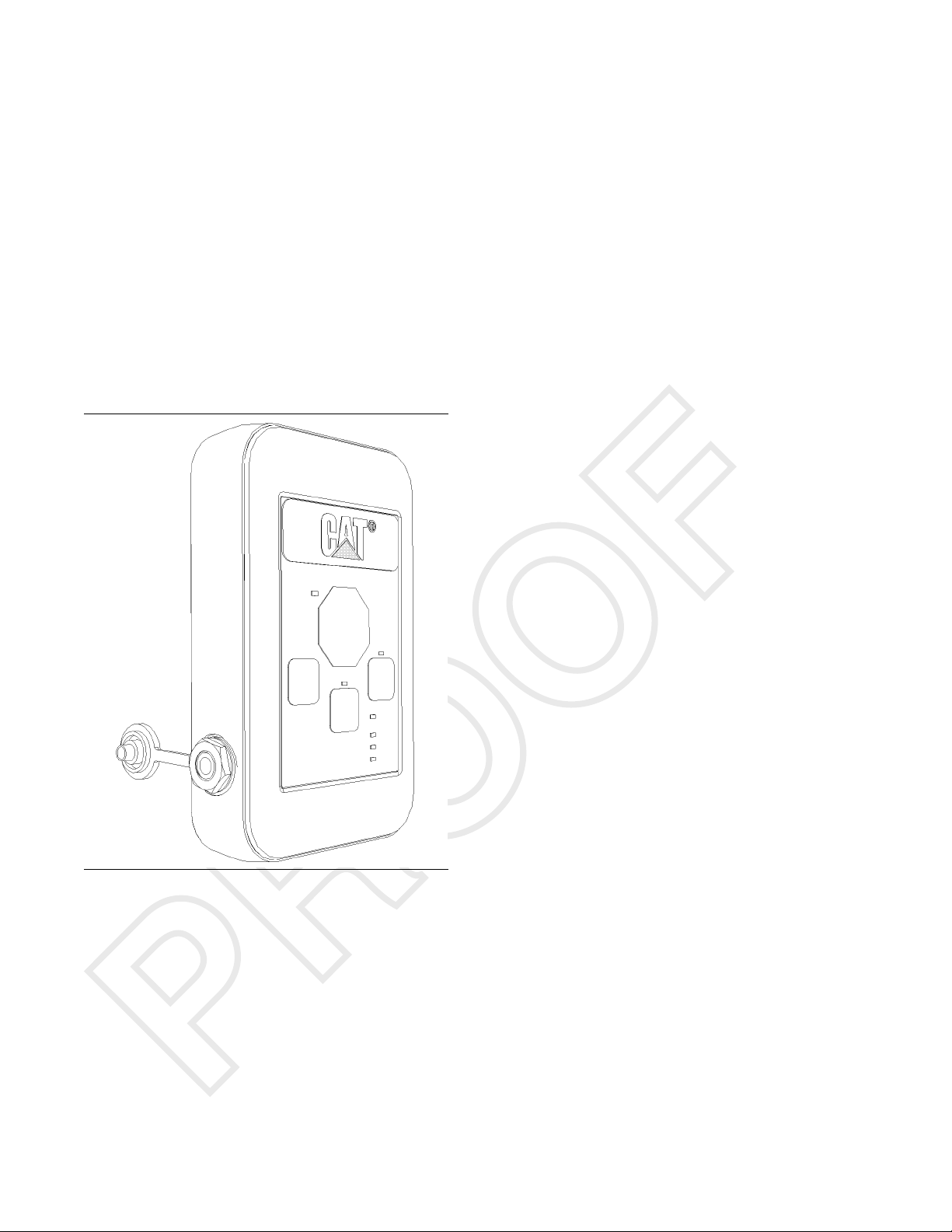
The A-Stop transmitter is a hand held unit that can
be carried by each individual within the area of
autonomous ope
1.2 V NiMH battery which is charged using the port
on the side of the transmitter. The transmitter sends
signals at a 91
receivers within the transmitter operating range. The
transmitter can stop every autonomous truck within
approximatel
indicator lights for Stop, Clear, Test, Low Battery,
Battery Charging, and Battery Fault functions. The
transmitter
24 hours of inactivity or can be triggered manually.
ration. It runs off a rechargeable,
9MHzfixed frequency to the A-Stop
y 300 m. The transmitter also has LED
will enter a power-saving sleep mode after
Electrical
Output Components
A-Stop Transmitter
Illustration 8
A-Stop Transmitter
g02799960
6
Page 7

7
Page 8

©2012 Caterpillar
All Rights Reserved
Cat, Caterpillar, their respective logos, “Caterpillar Yellow” and the Power edge
trade dress, as well as corporate and product identity used herein, are trademarks
of Caterpillar and may not be used without permission.
 Loading...