

Page 1
SERVICE MANUAL
& PARTS LIST
REF. NO. S/M-817
JUN. 2003
MODULE NO.
QW-2727/2730
WVA-400D WVA-400DJ
R
Ver.1 : Nov. 2003
(WITHOUT PRICE)
Page 2

CONTENTS
Page
1. SPECIFICATIONS: MODULE QW-2727/2730 ........................................... 1
2. OPERATION CHART: MODULE QW-2727 ............................................... 2
3. DRAWINGS: MODULE QW-2727/2730
3-1. LCD DIAGRAM ............................................................................................. 9
3-2. CIRCUIT DIAGRAM .....................................................................................10
3-3. CHECKING TERMINALS AND COMPONENTS ......................................... 12
3-4. N1, N2, R1~ R3 PADS ................................................................................. 13
4. EXPLODED VIEW: MODULE QW-2727/2730 .......................................... 14
5. PARTS LIST: MODULE QW-2727/2730 ................................................... 16
6. PRECAUTIONS FOR REPAIR: MODULE QW-2727/2730
6-1. AC (ALL CLEAR) AND REMOVING OF MODULE .....................................17
6-2. ACCURACY CHECKING ............................................................................. 17
6-3. SOLAR CELL-PCB ASS'Y CONTACT CHECKING....................................18
6-4. HOW TO CHECK TILT SENSOR................................................................. 18
7. TROUBLESHOOTING: MODULE QW-2727/2730.................................... 19
Page 3
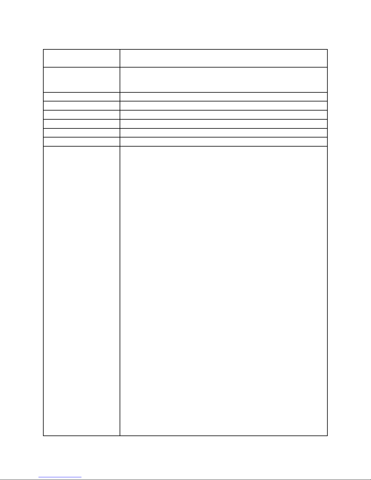
1. SPECIFICATIONS: MODULE QW-2727/2730
Item Detail
Battery CTL1616 (Storage battery)
Note: Use CTL1616 only. Other storage battery or CR1616 can cause
damage to the watch.
Battery life Approx. 5 months (from full charged condition)
Current consumption 0.568 µA maximum
Alarm system Piezo plate on Cover/Back
Accuracy ±15 sec./month
Accuracy setting system Trimmer capacitor
Accuracy checking See page 17
Functions • LED light
Afterglow
• Solar powered
• Time calibration signal reception
Auto receive
Manual receive
Last date/time received display
• Time Calibration Signal
QW-2727: Receivable Time Calibration Signals
Mainflingen, Germany (Call Sign: DCF77, Frequency: 77.5kHz)
QW-2730: Receivable Time Calibration Signals Fort Collins,
Colorado (Call Sign: WWVB, Frequency: 60kHz)
Fukushima, Japan (Call Sign: JJY, Frequency: 40kHz)
Fukuoka/Saga, Japan(Call Sign: JJY, Frequency: 60kHz)
• e-DATE MEMORY
Meomory capacity: Up to 40 records for Internet access codes and other
data (when there are 7characters per record), actual number of records
depends on the number of characters per record
• World Time
29 time zones (30 cities), daylight saving time on/off
• Time Memo
Memory for up to 10 time memos, each with date (month and day) and time
• 1/100-sec. stopwatch
Measuring capacity: 23:59’59.99"
Measuring modes: Elapsed time, split time, 1st-2nd place times
• Daily alarms
5 independent daily alarms snooze feature for one alarm only
• Hourly time signal
• Low battery warning display
• Auto-calendar (to year 2039)
• 12/24-hour format
• Regular timekeeping:
Analog: 3 hands (Hr, min, sec)
Digital: Hr, min, sec, pm, month, date, day
— 1 —
Page 4
2. OPERATION CHART: MODULE QW-2727
Getting Acquainted
Congratulations upon your selection of this CASIO watch. To get the most out of your
purchase, be sure to carefully read this manual and keep it on hand for later reference
when necessary.
Expose the watch to bright light to charge its battery before using it.
You can use this watch even as its battery is being charged by exposure to bright
light.
• Be sure to read “Battery” of this manual f or important information you need to
know when exposing the watc
If the digital display of the watch is blank...
l
l
l
l
l
l
l
l
l
l
l
l
l
h to bright light.
If the Power Saving indicator (PS) is flashing on the display,
it means that the display is blank because the watch’s
Power Saving function has turned off the display to
conserve power. Power Saving automatically turns off the
display and enters a sleep state whenever your watch is
left for a certain period where it is dark. If the watch is kept
in the dark for a longer period, the analog hands will also
stop moving after a few days.
• The initial factory default setting is Power Saving on.
• The watch recovers from the sleep state if you move it to
a well-lit area, if you press any button, or if you angle the
watch towards your face for reading.
• See “Power Saving Function” for more inf
ormation.
About This Manual
• Button operations are indicated using the letters shown
in the illustration.
• Each section of this manual provides you with the
information you need to perform operations in each
mode. Further details and technical information can be
found in the “Reference”
section.
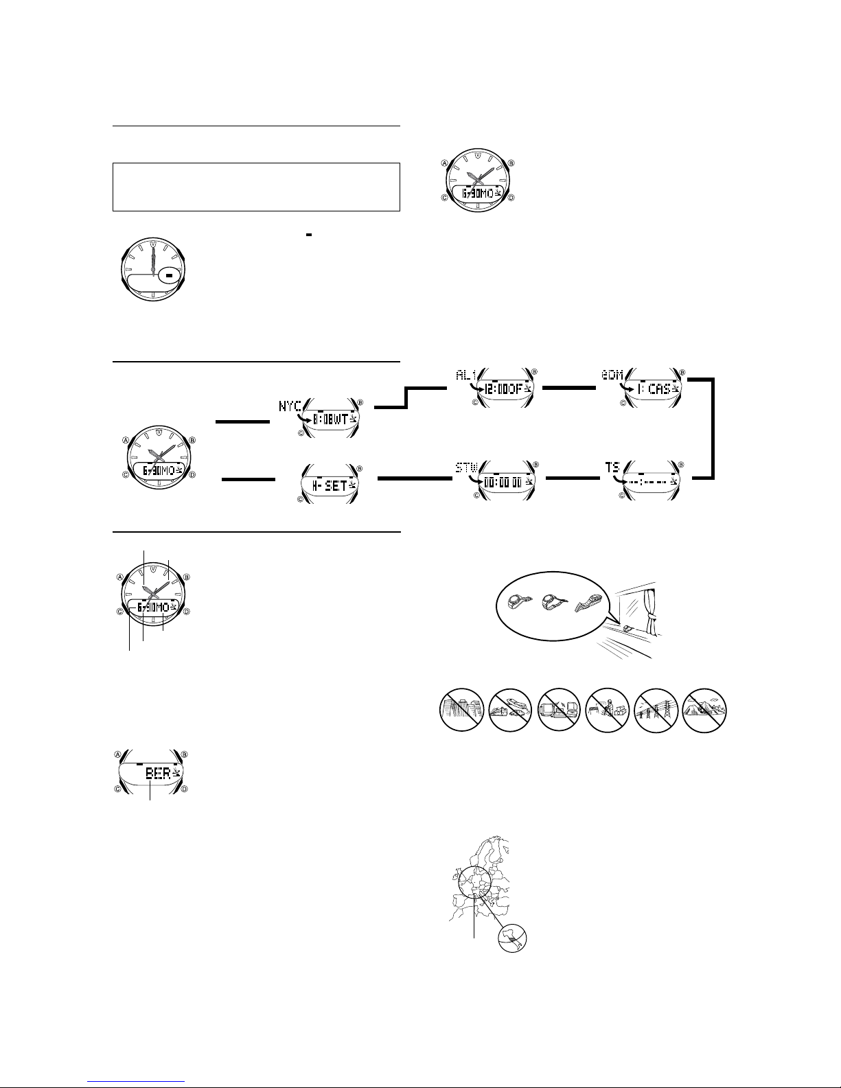
General Guide
• Press C to change from mode to mode.
• In any mode, press B to illuminate the display.
Timekeeping Mode
Press C
.
▲
World Time Mode
Hand Setting Mode
▲
Radio-controlled Timekeeping
Hour hand
Minute hand
Day of week
Seconds hand
Month – Day
To set your Home City
l
l
l
l
l
l
l
l
l
l
l
l
City code
Time Calibration Signal Reception
There are two different methods you can use to receive the time calibration signal:
auto receive and manual receive.
• Auto Receive
With auto receive, the watch automatically picks up the time calibration signal five
times a day at 0:00 a.m., 1:00 a.m., 2:00 a.m., 3:00 a.m., and 4:00 a.m. For more
information, see “About Auto Receive”.
• Manual Receive
Manual receive lets you start a time calibration receive operation with the press of a
button. For more information, see “To perform manual receive”.
This watch is designed to pick up a time calibration signal
transmitted from Mainflingen, Germany (located 25
kilometers southeast of Frankfurt), and update its time
setting accordingly. The time calibration signal includes
both Standard Time and Daylight Saving Time (summer
time) data.
Current Time Setting
This watch automatically adjusts its time setting in
accordance with a time calibration signal. You can also
perform a manual procedure to set the time and date,
when necessary.
• The first thing you should do after purchasing this watch
is to set your Home City, which is the city where you will
normally use the watch. For more information, see “To
set your Home City” below.
• See “Setting the Digital Time and Date Manually” for
information about manual settings
• The analog time of this watch is synchronized with the
digital time. Because of this, the analog time setting is
automatically adjusted whenever you change the digital
setting. See “Analog Timek eeping” f or more information.
1. In the Timekeeping Mode, hold down A until the city
code starts to flash, which indicates the setting screen.
• The second hand will move at high speed to the 12
l
l
l
l
l
o’clock position, where it will stop.
2. Use D (+) and B (–) to select the city code you want to
use as your Home City.
• The following are the city codes for major cities in the
Western Europe time zones.
BER
and
PAR
: Berlin, Paris, Milan, Rome,
Amsterdam, Hamburg,
LON
: London
3. Press A twice to e
• The second hand will advance at high speed to the
correct position in accordance with seconds count of the
digital time, and resume normal movement from there.
• Normally, your watch should show the correct time as
soon as you select your Home City Code. If it does not,
it should adjust automatically after the next auto receive
operation (in the middle of the night). You can also
perform manual receive or you can set the time
manually.
• If you are in an area that does not use Daylight Saving
Time (summer time), turn off the DST setting.
Frankfurt, Vienna
xit the setting screen.
.
Alarm Mode
▲
Stopwatch
Mode
▲
Important!
• Position the watch as shown in the nearby illustration, with its 12 o’clock side facing
towards a window. Make sure there are no metal objects nearby
• Proper signal reception can be difficult or even impossible under the conditions listed
below
.
Inside or
among
buildings
About Auto Receive
When auto receive is turned on, the watch automatically starts to receive the time
calibration signal when the time in the Timekeeping Mode reaches 0:00 a.m., 1:00
a.m., 2:00 a.m., 3:00 a.m., and 4:00 a.m. each day (calibration times). The watch will
also perform an additional auto receive operation at 5:00 a.m. if none of regularly
scheduled auto receive operations are successful.
Frankfurt
Inside a
vehicle
▲
Resin
Band
Metal Band
Near
household
appliances or
office
equipment
• Signal reception is normally better at night than during
the day.
• Time calibration signal reception takes from two to six
minutes. Take care that you do not perform any button
operations or move the watch during this time.
• This watch is able to receive the time calibration signal
transmitted from Mainflingen, Germany (located 25
kilometers southeast of Frankfurt). Signal reception is
possible within the area represented by a circle with a
radius of about 1,000 kilometers.
• At distances further than about 500 kilometers, the
signal may become weak and reception may be
impossible under certain conditions.
• Signal reception may be poor in the shaded area on the
map, even though it is within 1,000 kilometers of the
signal transmitter.
• See the information under “Signal Receive
Troubleshooting” if you experience problems with time
calibr
ation signal reception.
Data Memory Mode
▲
Time Recorder Mode
Near a
construction
site, airport, or
other sources
of electrical
noise
.
Near hightension
power lines
▲
Among or
behind
mountains
— 2 —
Page 5
Note
•
The auto receive operation is performed only if the watch is in the Timekeeping
Mode or World Time Mode when one of the calibration times is reached. It is not
performed if a calibration time is reached while an alarm is sounding, or while you
are configuring settings (while settings are flashing on the display).
•
When a receive operation starts, the second hand will move at high speed to the 12
o’clock position where it will stop until the receive operation is complete.
•
Auto receipt of the calibration signal is designed to be performed early in the
morning, while you sleep (provided that the Timekeeping Mode time is set correctly).
Before going to bed for the night, remove the watch from your wrist, and put it in a
location where it can easily receive the signal.
•
When auto receive is turned on, the watch receives the calibration signal for two to
six minutes everyday when the time in the Timekeeping Mode reaches each of the
five calibration times. Do not perform any button operation within six minutes before
or after any of the five calibration times. Doing so can interfere with correct
calibration.
•
Remember that reception of the calibration signal depends on the time kept in the
digital display. The receive operation will be performed whenever the display shows
one of the five calibration times, regardless of whether or not the displayed time is
actually the correct time.
•
When two, three, four, or five receptions are successful, the watch uses the data of
the last reception for calibration. When only one reception is successful, the watch
uses the data of the successful reception.
About the Receiving Indicator
The receiving indicator shows the strength of the calibration signal being received. For
best reception, be sure to keep the watch in a location where signal strength is
strongest.
Receiving indicator
l
l
l
l
l
l
l
l
l
l
l
l
l
l
l
•
Even in an area where signal strength is strong, it takes about 10 seconds for signal
reception to stabilize enough for the receiving indicator to indicate signal strength.
•
Use the receiving indicator as a guide for checking signal strength and for finding the
best location for the watch during signal receive operations
•
The Level 4 receiving indicator remains on the display in all modes following
reception of the time calibration signal and calibration of the watch’s time setting.
The Level 4 receiving indicator is not displayed if signal reception was unsuccessful
or after manual adjustment of the current time setting.
•
The Level 4 receiving indicator indicates that at least one of the five calibration
signal receive operations was successful. Note, however , that the Level 4 receiving
indicator is cleared from the display at 3:00 a.m. each day.
To perform manual receive
Receiving indicator
l
l
l
l
l
l
l
l
l
l
Note
•
To interrupt a receive operation and return to the Timekeeping Mode, press D.
•
If the receive operation is unsuccessful, the message
for about one or two minutes. After that, the watch returns to the Timekeeping Mode.
•
You can also change from the Last Signal or
timekeeping screen by pressing
To turn auto receive on and off
On/off status
l
l
l
l
l
l
l
l
l
l
l
l
l
To display the Last Signal screen
In the Timekeeping Mode, press D to display the Last Signal screen. The Last Signal
screen shows the date and time that the time calibration signal was last receiv
l
l
l
l
l
l
l
l
l
l
l
l
l
l
Weak
(Level 1)
Strong
(Le
vel 4)
.
1.Place the watch on a stable surface so its top (12
o’clock side) is facing towards a window.
•
Note that signal reception will be poor if the watch is
on its back or side.
l
l
2.In the Timekeeping Mode, hold down
l
l
l
l
l
l
l
l
l
l
l
l
l
seconds until the watch beeps.
l
l
l
l
3.Release
D
and the current time or date flashes to
indicate that signal reception has started.
•
When a receive operation starts, the second hand will
move at high speed to the 12 o’clock position where it
will stop until the receive operation is complete
•
Time calibration signal reception takes from two to six
minutes. Take care that you do not perform any button
operations or move the watch during this time.
•
After signal reception is complete, the display of the
watch changes to the Last Signal screen.
ERR
ERR
D
.
1.In the Timekeeping Mode, hold down A until the city
code starts to flash, which indicates the setting screen.
•
The second hand will move at high speed to the 12
o’clock position, where it will stop.
C
twice to move the flashing to the auto receive
2.Press
on/off setting.
3.Press
D
to toggle auto receive on (ON) and off (OF).
•
If the current Home City setting is a city code that
does not support auto receive, “
of the on/off indicator. This means you cannot turn
auto receive on or off.
A
twice to exit the setting screen.
4.Press
•
The second hand will advance at high speed to the
correct position in accordance with the digital time
seconds count, and resume normal movement from
there
.
screen to the normal
D
for about two
.
appears on the display
__
” appears in place
ed.
Receive time
Alternate at twosecond interva
l
Press .
▲
▲
Receive date
Last Signal Screen
Signal Receive Troubleshooting
Check the following points whenever you experience problems with calibration signal
reception.
Problem
Cannot perform
manual receive
Auto receive is
turned on, but
the Level 4
receiving
indicator does
not appear on
the display
Time setting is
incorrect
following signal
reception.
•
For further information, see “Time Calibration Signal Reception” and “Time
Calibration Signal Reception Precautions”
.
.
Probable Cause
•
The watch is not in the Timekeeping Mode.
• Your current Home City is not one of the
follo
wing city codes:
BER, PAR , LON, or AT H.
You changed the time setting manually.
••The watch was not in the Timekeeping
or World Time Mode, or you w ere
performing some button operation
during the auto receive operation.
•
Even if receive is successful, the Level 4
receiving indicator disappears every day
at 3 a.m.
• If the time is one hour off, the DST
setting may be incorrect.
• The Home City code setting is not
correct for the area where you are using
tch.
the wa
.
What you should do
• Enter the Timekeeping Mode
and try again.
• Select BER, PAR, LON, or
ATH as your Home City
• Perform manual signal receive
or wait until the next auto
signal receive operation is
performed.
• Check to make sure the watch
is in a location where it can
receive
the signal.
• Change the DST setting to
Auto DST.
• Select the correct Home City
code
.
.
Timekeeping
Use the Timekeeping Mode to set and view the current time and date.
Day
Month —
Press .
▲
Day of week
Setting the Digital Time and Date Manually
Make sure you select your Home City code before you change the current time and
date settings. World Time Mode times are all displayed in accordance with the
Timekeeping Mode settings. Because of this, World Time Mode times will not be
correct if you do not select the proper Home City code before setting the time and
date in the Timekeeping Mode
To set the current digital time and date manually
l
l
l
l
l
l
l
l
l
l
l
l
l
l
City code
3. When the setting you want to change is flashing, use and/or to change it as
described below
Screen: To do this:
BER
DST
R/C
12H
Screen (flashing):
P
'02
ON
4. After configuring the Power Saving on/off setting, press to exit the setting screen.
•
The second hand will advance at high speed to the correct position in accordance
with the digital time seconds count, and resume normal movement from there.
•
See “City Code Tab le” for a complete list of av ailable city codes .
•
See “Power Saving Function” for details about the Power Saving.
•
The auto receive setting is used for time calibration signal reception only. See “About
Auto Receive” for details
Change the city code
Toggle between Daylight Saving
Time (ON) and Standard Time
(
OF
Toggle between auto receiv
(
ON
Toggle between 12-hour (
24-hour (
.
1.In the Timekeeping Mode, hold down
code starts to flash, which indicates the setting screen.
•
l
l
l
The second hand will move at high speed to the 12
o’clock position, where it will stop.
A
2.Press or
shown below to select other settings
Press
12/24-Hour
Format
Power
Saving
.
)
) and off (OF)
) timekeeping
24H
To do this:
Reset the seconds to
Change the hour
Change the minu
Change the ye
Change the month
Change the day
Toggle Power Saving on
(
) and off (OF)
ON
.
Hour: Minutes Seconds
A
▲
A
until the city
C
to move the flashing in the sequence
/ Press
C
.
DSTCity Code
Seconds
Day
e on
) and
12H
tes
ar
.
A
.
Auto
Receive
Hour Minutes
Month Year
D
B
Do this:
Use
D
(+) and
B
D
.
Press
D
• Pressing
Press
performs a
different operation when
BER, PAR, LON, or ATH is
selected as Home City code.
See “To change the Daylight
Saving
Time (summer time)
setting”.
D
.
Press D.
Do this:
Press D.
Use
D
(+) and B (–).
D
.
Press
A
(–).
— 3 —
Page 6
Daylight Saving Time (DST)
Daylight Saving Time (summer time) advances the time setting by one hour from
Standard Time. Remember that not all countries or even local areas use Daylight
Saving Time.
The time calibration signal transmitted from Mainflingen includes both Standard Time
and DST data. When the DST setting is turned on, the watch switches between
Standard Time and DST (summer time) automatically in accordance with the
Mainflingen signal.
•
The default DST setting is Auto DST (
or
ATH
as your Home City code.
•
If you experience problems receiving the time calibration signal in your area, it is
probably best to switch between Standard Time and Daylight Saving Time (summer
time) manually .
To change the Daylight Saving Time (summer time) setting
1. In the Timekeeping Mode, hold down A until the city code starts to flash, which
indicates the setting screen.
2. Press C and the DST setting screen appears.
3. Use D to cycle through the DST settings in the sequence shown below.
Auto DST (A) DST off (OF) DST on (
4. When the setting you want is selected, press A twice to e
Analog Timekeeping
The analog time of this watch is synchronized with the digital time. The analog time
setting is adjusted automatically whenever you change the digital time.
Note
•
The hands for the analog timepiece move to adjust to a new setting whenever any of
the following occurs.
When you change the digital time setting manually
When the digital time setting is changed by time calibration signal reception
When you change the Home City code and/or DST setting
•
If the analog time does not match the digital time for any reason, use the procedure
described under “To adjust the analog time” to match the analog setting to the digital
setting.
•
Whenever you need to adjust both the digital and the analog time settings manually,
make sure you adjust the digital setting first.
•
Depending on how much the hands have to move in order to adjust to the digital
time, it may take some time before the analog hands stop mo
To adjust the analog time
l
l
l
l
l
l
l
l
l
l
l
l
l
l
l
l
When you want to do this:
Move the hand setting
forw
ard 20 seconds
Move the hand setting back
20 seconds
Move the hand setting a short
ard at high speed
way forw
Move the hand setting a
short way bac
Move the hand setting a
long way forward at high
speed
Move the hand setting a long
way back
6. Press A to exit the setting screen.
•
The minute hand will be adjusted slightly to match the seconds when you exit the
setting screen.
•
To return to the Timekeeping Mode, press C.
k at high speed
at high speed
A
) whenever you select
1.In the Timekeeping Mode, press C six times to enter
the Hand Setting Mode.
2.Hold down A until
the setting screen.
•
The second hand will move at high speed to the 12
o’clock position, where it will stop.
3.If the second hand is not pointing precisely at 12 o’clock
at this time, use D to adjust its position.
•
Each press of D causes the second hand to advance
by one second.
4.Press C. This will cause the time on the digital display
to flash, which indicates that adjustment of hour and
minute hands is selected.
5. Use D and B to adjust the analog setting as
described below
•
Press D.
•
Press B.
•
Hold down D.
•
Release D when the hands reach the setting
you want.
•
Hold down B.
•
Release B when the hands reach the setting
you want.
•
While holding down D to move the hands at
high-speed, press B to lock the high-speed
hand movement.
•
To stop the hand movement, press any
button.
•
Hand movement stops automatically if the hour
hand makes one full (12-hour) revo
•
While holding down B to move the hands at
high-speed, press D to lock the high-speed
hand movement.
•
To stop the hand movement, press any
button.
•
Hand movement stops automatically if the hour
hand makes one full (12-hour) revo
“” starts to flash, which indicates
.
Perform this button operation:
BER, PAR, LON
ON
)
xit the setting screen.
ving.
lution.
lution.
World Time
City Code
,
Current time in the
selected city code
To view the time in another city
While in the World Time Mode, press D to scroll through the city codes (time zones).
• For full information on city codes, see the “City Code Table”.
To toggle a city code time between Standard Time and Daylight Saving Time
DST indicator
The World Time Mode digitally displays the current time in
30 cities (29 time zones) around the world.
•
Pressing A in the World Time Mode causes the
applicable city code to appear on the digital display for
about two seconds.
•
If the current time shown for a city is wrong, check your
Home City time settings and make the necessary
changes.
•
The watch will perform a signal receive operation even if
it is in the World Time Mode when a calibration time is
reached. If this happens, the World Time Mode time
settings will be adjusted in accordance with the
Timekeeping Mode’s Home City time.
•
All of the operations in this section are performed in the
World Time Mode, which you enter by pressing C.
1.In the World Time Mode, use D to display the city code
(time zone) whose Standard Time/Daylight Saving Time
setting you want to change.
•
Pressing A in the World Time Mode causes the
applicable city code to appear on the digital display for
about two seconds.
2.Hold down A to toggle Daylight Saving Time (
displayed) and Standard Time (
•
Note that you cannot use the World Time Mode to
change the DST setting of the Home City code you
currently have selected in the Timekeeping Mode. See
“Daylight Saving Time(DST)” for information about
turning the Home City code DST setting on and off
DST
•
The
indicator will appear on the display whenever
you display a city code for which Daylight Saving Time is
turned on.
•
Note that the DST/Standard Time setting affects only the
currently displayed city code. Other city codes are not
aff
ected.
DST
DST
not displayed).
.
Alarms
The Alarm Mode gives you a choice of four one-time
Alarm name
Alarm time
(Hour : Minutes)
To set an alarm time
l
l
l
l
l
l
l
l
l
l
l
l
l
l
l
l
l
l
l
l
l
l
l
l
Target Alarm Screen
Alarm Operation
The alarm tone sounds at the preset time for 10 seconds, regardless of the mode the
watch is in. In the case of the snooze alarm, the alarm operation is performed a total
of seven times, every five minutes, or until you turn the alarm off.
The target alarm counts the time remaining from the current Home City time to the
target alarm time.
•
Pressing any button stops the alarm tone operation.
•
Performing any one of the following operations during a 5-minute interval between
snooze alarms cancels the current snooze alarm operation.
Displaying the Timekeeping Mode setting screen
Displaying the alarm setting screen
To test the alarm
In the Alarm Mode, hold down D to sound the alarm.
alarms and one snooze alarm. One of the one-time
alarms functions as a “target alarm,” which counts the time
remaining from the current Home City time to the target
alarm time.
You should also use the Alarm Mode to turn the Hourly
Time Signal on and off.
•
There are five alarms named
(target alarm), and
snooze alarm only. Alarms
TAL
can be used as one-time alarms only.
•
All of the operations in this section are performed in the
Alarm Mode, which you enter by pressing C.
1.In the Alarm Mode, use D to scroll through the alarm
screens until the one whose time you want to set is
displayed.
AL1 AL2 AL3
SIG SNG TAL
2.After you select an alarm, hold down until the hour
setting of the alarm time starts to flash, which indicates
the setting screen.
•
This operation automatically turns on the alarm.
3.Press C to move the flashing between the hour and
minute settings.
4.While a setting is flashing, use D (+) and B (–) to
change it.
•
When setting the alarm time using the 12-hour format,
take care to set the time correctly as a.m. (no
indicator) or p.m. (P indicator).
5.Press A to exit the setting screen.
•
With the target alarm (
countdown as soon as you set the alarm time.
AL1, AL2, AL3, TAL
SNZ SNZ
. You can configure
AL1, AL2, AL3
TAL
), the time starts to
, and
as a
— 4 —
Page 7
To select the alarm operation type
Snooze on
Alarm on
indicator
indicator
To turn the Hourly Time Signal on and off
Hourly time signal
on indicator
1.In the Alarm Mode, use D to select the screen for the
alarm (
AL1, AL2, AL3, TAL
alarm type you want to select.
2.Press A to cycle through the available settings in the
sequence shown below.
Alarm/
Snooze off
• The alarm on indicator (ALM) or snooze on indicator
(SNZ) is displayed for each alarm (
TAL, SNZ
• The snooze on indicator (SNZ) flashes during the 5-
minute interval between snooze alarms.
• The alarm on indicator (ALM) and snooze on indicator
(SNZ) are displayed in all modes.
• In all modes, the alarm on indicator (ALM) is shown for
any alarm (
tur
1.In the Alarm Mode, use D to select the Hourly Time
2.Press A to toggle it on (SIG displayed) and off (SIG
• The Hourly Time Signal on indicator (SIG) is displayed
in all modes when the Hourly Time Signal is tur
) for which alarm on is selected.
AL1, AL2, AL3, TAL
ned on.
Signal (
SIG
).
not displayed).
, or
Alarm/
Snooze on
AL1, AL2, AL3
SNZ
) whose
) that is currently
ned on.
Data Memory
You can use the watch’s data memory to store e-mail
addresses, Web page URLs, and other te xt data.
• All of the operations in this section are performed in the
Data Memory Mode, which you enter by pressing C.
Data Memory Records
Each data memory record can contain up to 63
characters. Records are stored in memory in the
Text
Record number
To create a new data memory record
Cursor
l
l
l
l
l
l
l
l
l
Text
Record number
To recall data memory records
1. In the Data Memory Mode, press D to scroll forward through data memory records.
• Each press of D advances to the next record and shows its record number and
first three characters of its text.
• Pressing D while the last record in memory is on the display changes to the
remaining memory screen. Pressing D again displays the first record.
2. Use A to scroll through the text, three characters at a time.
First three characters
Each press of A shows the next three characters.
• An end mark indicates the end of the te
To edit a data memory record
1. In the Data Memory Mode, display the record you want to edit.
2. Hold down A until the flashing cursor appears on the display.
3. Press C to move the flashing to the character you want to change.
4. Use D and B to change the character.
5. After making the changes you want, press A to store them and return to the data
memory record screen.
To delete a data memory record
1. In the Data Memory Mode, display the record you want to delete.
2. Hold down A until the flashing cursor appears on the display.
3. Press B and D at the same time to delete the record.
•The message CLR appears to indicate that the record is being deleted. After the
record is deleted, the cursor appears on the display, ready for input.
4. Input data or press A to return to the remaining memor
sequence they are created.
• The number of records you can store in data memory
depends on the number of characters that make up
each record. See “Data Memory Management” for more
infor
mation.
1.In the Data Memory Mode, press A and D at the
same time to display the remaining memory screen.
• You do not have to perform the above step if the
remaining memory screen is already on the display.
• If 0% is shown for remaining memory, it means that
memory is full. To store another record, you will first
have to delete some of the records stored in memory.
2.Hold down A until the flashing cursor appears on the
display, which indicates the setting screen.
3.Use B and D to cycle through characters at the
current cursor location, and C to move the cursor to
the right. See “Inputting Text” for more information.
• If memory becomes full while you are inputting text,
the cursor will jump to the first (leftmost) character of
the text when you press C, instead of advancing to
the ri
ght.
4.Press A to store your data and return to the data
memory record screen (without the cursor).
• The message SET appears for about two seconds,
followed by a data memory record screen, which shows
the text you just input, along with a record number
automatically assigned by the w
Second three characters
atch.
End mark
xt.
y screen.
,
— 5 —
Time Recorder
The Time Recorder Mode lets you store up to 10 time
entries (month, day, hour, minutes, seconds) with the
touch of a button. One way you can use the Time
Recorder Mode is to record the start time and the end
time of a particular event.
• All of the operations in this section are performed in the
Time Recorder Mode, which you enter by pressing CC.
To record a Time Recorder time
Hour : Minutes Seconds
Standby Screen
To recall Time Recorder times
1. In the Time Recorder Mode, press A to recall Time Recorder times.
2. Use D to scroll through times stored in memory.
Time record number
• Each press of D scrolls through time records from higher numbered (newer)
records to lower numbered records.
• If you recorded a new Time Recorder time since you last entered the Time Recorder
Mode, the newest record appears first. If you have not recorded a new time, the
record you were viewing when you last viewed the Time Recorder times appears first.
To delete all Time Recorder times
In the Time Recorder Mode, press A and D at the same time to delete all Time
Recorder times
.
1.Use C to enter the Time Recorder Mode.
This displays the Time Recorder standb
2.Press D to record the current date and time (month,
day, hour, minutes, seconds).
•• The recorded time flashes for about two seconds and
then assigned the next available record number, in the
ange of through . Next the time recorder standby
r
screen appears.
• A new time is recorded each time you press D while
the standby screen is on the display.
•
Records are assigned numbers sequentially from
through .
• Storing a new time record when there are already 10
records stored in memor
shifts the remaining records upwards by 1, and stores
the ne
w record as .
▲
Recorded time
(Month – Day)
y automatically deletes record ,
Alternate at twosecond interval
▲
y screen.
▲
Recorded time
(Hour : Minutes Seconds)
Stopwatch
The stopwatch lets you measure elapsed time, split times,
and two finishes.
• The display range of the stopwatch is 99 minutes, 59.99
seconds.
• The stopwatch continues to run, restarting from zero
after it reaches its limit, until you stop it.
• Exiting the Stopwatch Mode while a split time is frozen
on the display clears the split time and returns to
Minutes
Seconds
1/100 second
elapsed time measurement.
• The stopwatch measurement operation continues even
if you exit the Stopwatch Mode.
• All of the operations in this section are performed in the
Stopwatch Mode, which you enter by pressing
.
To measure times with the stopwatch
Elapsed Time
D
Start Stop
D
➤ ➤
D
Re-start Clear
D
➤
Stop
A
➤
Split Time
A
D
Start Split
➤
A
➤
Split release
D
➤
Stop
A
➤
Clear
Two Finishes
D
Start Split
A
➤
First runner
finishes.
Display time of
first runner.
D
➤
Stop
Second runner
finishes.
A
➤
Split release
Display time of
second runner
A
➤
Clear
.
Backlight
The backlight uses an LED (light-emitting diode) and a
Auto light switch
on indicator
light guide panel that cause the entire display to glow for
easy reading in the dark. The watch’s auto light switch
automatically turns on the backlight when you angle the
watch towards your face in the dark.
• The auto light switch must be turned on (indicated by
the auto light switch on indicator) for it to operate.
• See “Backlight Precautions” for other important
information about using the backlight.
To turn on the backlight manually
In any mode, press B to illuminate the display for about
one second.
• The above operation turns on the backlight regardless of
the current auto light sw
itch setting.
Page 8

About the Auto Light Switch
Turning on the auto light switch causes the backlight to turn on for about one second,
whenever you position your wrist as described below in any mode. Note that this
watch features a “Full Auto LED Light,” so the auto light switch operates only when
available light is below a certain level. It does not turn on the backlight under bright
light.
Moving the watch to a position that is parallel to the ground and then tilting it
towards you more than 40 degrees causes the backlight to turn
Parallel to
ground
Warning!
• Always make sure you are in a safe place whenever you are reading the
display of the watch using the auto light switch. Be especially careful when
running or engaged in any other activity that can result in accident or injury.
Also take care that sudden illumination by the auto light switch does not
surprise or distract others around you.
• When you are wearing the watch, make sure that its auto light switch is turned
off before riding on a bicycle or operating a motorcycle or any other motor
vehicle. Sudden and unintended operation of the auto light switch can create a
distraction, which can result in a traffic accident and serious personal injury.
To turn the auto light switch on and off
In the Timekeeping Mode, hold down B for about two seconds to toggle the auto light
switch on (the auto light switch on indicator displayed) and off (the auto light switch on
indicator not displayed).
• The auto light switch on indicator is on the display in all modes while the auto light
switch is tur
ned on.
on.
More than
40°
Battery
This watch is equipped with a solar cell and a rechargeable battery (secondary
battery) that is charged by the electrical power produced by the solar cell. The
illustration shown below shows how you should position the watch for charging.
Example: Orient the watch so its
face is pointing at a light source.
• Note that charging efficiency
drops when any part of the solar
cell is blocked by clothing, etc.
• The illustration shows how to
position a watch with a resin band.
Important!
• Storing the watch for long periods in an area where there is no light or wearing it in
such a way that it is blocked from exposure to light can cause rechargeable battery
power to run down. Be sure that the watch is normally exposed to bright light
whenever possible
• Normally, the rechargeable battery should not need replacement, but after very long
use over a number of years, the rechargeable battery may lose its ability to achieve
a full charge. Should you notice problems with getting the rechargeable battery to a
full charge, contact your dealer or CASIO distributor about having the rechargeable
battery replaced.
• The rechargeable battery should be replaced with a CASIO-specified CTL1616
battery only. Other rechargeable batteries can cause damage to the watch.
• All data stored in memory is deleted, and the current time and all other settings
return to their initial factory defaults whenever battery power drops to Level 4 and
when you have the battery replaced.
• Turn on the watch’s Power Saving function and keep it in an area normally exposed
to bright light when storing it for long periods. This helps to keep the rechargeable
battery from going dead.
Battery Power Indicator
The battery power indicator on the display shows you the current status of the
rechargeable battery’s power
Battery power indicator
• The flashing CHARGE indicator (C) at Level 3 tells you that battery power is very
low, and that exposure to bright light for charging is required as soon as possible.
• At Level 4, all functions are disabled and settings return to their initial factory
defaults. Functions are enabled once again after the rechargeable battery is
charged, but you need to set the time and date, after the battery reaches Level 3
(indicated by flashing CHARGE indicator (
configure any of the other settings until the battery reaches Level 2 (no CHARGE
indicator) after dropping to Level 4.
• Leaving the watch in direct sunlight or some other very strong light source can
cause the battery power indicator to temporarily show a reading that is higher than
the actual battery level. The correct battery power indicator should appear after a
few minutes.
• If you use the light or alarms a number of times during a short period, a RECOVER
indicator (
until battery power recovers.
Backlight
Beeper tone
Coordination between digital and analog timekeeping
Time calibration signal reception
After some time, battery power will recover and the RECOVER indicator will
disappear, indicating that the above functions are enabled again.
.
.
Battery Po
vel
Le
Indicator
Mid
Hi
1
Mid
Hi
2
3
Mid
Hi
Mid
Hi
4
R
) appears on the display and the following operations become disabled
Function Status
wer
w
Lo
All functions enabled.
w
Lo
All functions enabled.
Auto and manual signal
Low
l
C
l
l
l
l
l
l
l
l
l
l
l
l
l
receive, alarm, hourly time
signal, backlight, and display
are disabled. Though the hands
of the watch do not move, time
continues to be kept internally.
All functions, including
Lo
w
timekeeping, disabled.
C
) ) from Level 4. You will not be able to
Solar cell
Charging Precautions
Certain charging conditions can cause the watch to become very hot. Avoid leaving
the watch in the areas described below whenever charging its rechargeable battery.
Also note that allowing the watch to become very hot can cause its liquid crystal
display to black out. The appearance of the LCD should become normal again when
the watch returns to a lower temperature.
Warning!
Leaving the watch in bright light to charge its rechargeable battery can cause it
to become quite hot. Take care when handling the watch to avoid burn injury.
The watch can become particularly hot when exposed to the following
conditions for long periods.
• On the dashboard of a car parked in direct sunlight
• Too close to an incandescent lamp
• Under direct sunlight
Charging Guide
After a full charge, timekeeping remains enabled for up to about 5 months, while the
watch is used under the conditions described below.
Operating Conditions
•
Watch is not exposed to light
•
1 backlight operation (1.5 seconds) per day
•
10 seconds of alarm operation per day
•
5 time calibration signal receptions per day
Charge Times
Exposing the watch to light for the periods shown below each day restores the power
used by the above operating conditions.
Exposure Le
vel (Brightness)
Outdoor Sunlight (50,000 lux)
Sunlight Through a Window (10,000 lux)
Daylight Through a Window on a Cloudy Da
(5,000 lux)
Indoor Fluorescent Lighting (500 lux)
Approximate Exposure
5 minu
24 minutes
y
48 minu
8 hours
tes
tes
Time
• Stable operation is promoted by frequent charging.
Recovery Times
The table below shows the amount exposure that is required to take the battery from
one level to the ne
Exposure Level
(Brightness)
Outdoor Sunlight (50,000 lux)
Sunlight Through a Windo
(10,000 lux)
Daylight Through a
on a Cloudy Day (5,000 lux)
Indoor Fluorescent Lighting
(500 lux)
The above exposure time values are all for reference only. Actual required exposure
•
times depend on lighting conditions.
xt.
Window
Approximate Exposure Time
Level 4 Level 3 Level 2 Lev
▲
▲
1 hour
w
3 hours
5 hours
45 hours
13 hours
66 hours
▲
– –
– – –
el 1
4 hours
18 hours
–
Reference
This section contains more detailed and technical information about watch operation.
It also contains important precautions and notes about the various features and
functions of this watch.
Power Saving Function
l
l
l
l
Power Saving
indicator
Approximate Pe
in sleep state
3 to 4 da
ys
ys or more
8 da
The sleep state is indicated by a blank screen with the Power Saving indicator (PS)
flashing on it.
Wearing the watch inside the sleeve of clothing can cause it to enter the sleep state.
• • Even when the watch is in the sleep state, digital-analog time coordination and auto
signal receive are both performed.
To recover from the sleep state
Perform any one of the following operations.
• Move the watch to a well-lit area.
• Press any button.
• Angle the watch towards your face for reading.
When turned on, the Power Saving function automatically
enters a sleep state whenever the watch is left in an area
where lighting is dim (less than about 30 lux).
The following shows how watch functions are affected
l
l
when left in a dark place while in the sleep state
l
l
l
l
l
l
l
riod
• LCD off
• Alarm, hourly time signal, analog timek
signal receive enabled
• LCD off, alarm and hourly time signal disabled
• Analog timekeeping stopped at 12 o’clock
• Auto signal receive disab
Functions
led
.
eeping and auto
▲
— 6 —
Page 9

To turn Power Saving on and off
l
l
l
l
l
l
l
l
l
l
l
l
l
l
Auto Return Features
• If you leave the watch in the Alarm, Data Memory, or Hand Setting Mode for two or
three minutes without performing any operation, it automatically returns to the
Timekeeping Mode.
• If you leave the watch with a flashing setting or cursor on the display for two or three
minutes without performing any operation, the watch automatically exits the setting
screen.
Scrolling
The B and D buttons are used in various modes and setting screens to scroll
through data on the display. In most cases, holding down these buttons during a scroll
operation scrolls through the data at high speed.
Initial Screens
When you enter the World Time, Alarm, or Data Memory Mode, the data you were
viewing when you last exited the mode appears first.
Time Calibration Signal Reception Precautions
• Strong electrostatic charge can result in the wrong time being set.
• Even when the watch is within the reception range of the transmitter, signal
reception is impossible if the signal is blocked by mountains or other geological
formations between the watch and signal source.
• Signal reception is affected by weather, atmospheric conditions, and seasonal
changes.
• The time calibration signal is bounced off the ionosphere. Because of this, such
factors as changes in the reflectivity of the ionosphere, as well as movement of the
ionosphere to higher altitudes due to seasonal atmospheric changes or the time of
day may change the reception range of the signal and make reception temporarily
impossible.
• Even if the time calibration signal is received properly, certain conditions can cause
the time setting to be off by up to one second.
• The current time setting in accordance with the time calibration signal takes priority
over any time settings you make.
• The watch is designed to automatically update the date and day of the week for the
period January 1, 2000 to December 31, 2099. Setting of the date by the time
calibration signal cannot be performed starting from January 1, 2100.
• This watch can receive signals that differentiate between leap years and non-leap
years.
• Though this watch is designed to receive both time data (hour, minutes, seconds)
and date data (year, month, day), certain signal conditions can limit reception to time
data only.
• When all five auto receptions are successful (0:00 a.m., 1:00 a.m., 2:00 a.m., 3:00
a.m., and 4:00 a.m.), the watch uses the data of the last reception for calibration.
When only one reception is successful, the watch uses the data of the successful
reception.
• Normally, the signal reception date shown by the Last Signal screen is the date data
included in the received time calibration signal. When only time data is received,
however, the Last Signal screen shows the date as kept in the Timekeeping Mode at
the time of signal reception.
• If you are in an area where proper time calibration signal reception is impossible, the
watch keeps time within 15 seconds a month at normal temperature.
• If you have problems with proper time calibration signal reception or if the time
setting is wrong after signal reception, check your current city code, DST (summer
time), and auto receive settings. The following are the initial factory defaults for these
settings
.
Setting
City code
DST (summer time)
Auto receiv
e
Timekeeping
• Resetting the seconds to 00 while the current count is in the range of 30 to 59
causes the minutes to be increased by 1. In the range of 00 to 29, the seconds are
reset to 00
• The day of the week is automatically displayed in accordance with the date (year,
• The year can be set in the range of 2000 to 2099.
• The watch’s built-in full automatic calendar makes allow ances for different month
• The current time for all city codes in the Timekeeping Mode and World Time Mode is
• GMT differential is calculated by this watch based on Universal Time Coordinated
* The letters “UTC” stands for “Universal Time Coordinated,” which is the world-wide scientific
without changing the minutes.
month, and day) settings.
lengths and leap years. Once you set the date, there should be no reason to change
it except after you have the watch’s battery replaced or when battery power drops to
Level 4.
calculated in accordance with the Greenwich Mean Time (GMT) differential for each
city, based on your Home City time setting.
(UTC*) data.
standard of timekeeping. It is based upon carefully maintained atomic (cesium) clocks that
keep time accurately to within microseconds. Leap seconds are added or subtracted as
necessary to keep UTC in sync with the Earth’s rotation. The reference point for UTC is
Greenwich, England.
1.In the Timekeeping Mode, hold down A until the city
code starts to flash, which indicates the setting screen.
l
l
l
l
• The second hand will move at high speed to the 12
l
l
o’clock position, where it will stop.
2.Press A again.
3.Press C seven times until the Power Saving on/off
screen appears.
4.Press D to toggle Power Saving on (
(
).
OF
5.Press A to e
• The second hand will advance at high speed to the
correct position in accordance with the digital time
seconds count, and resume normal movement from
there.
• The Power Saving indicator (
modes while the Power Saving is turned on.
xit the setting screen.
±
Initial Factor
BER
A
DST
ON R/C
y Default
(Berlin)
(Auto switching)
(Auto receive)
) and off
ON
PS
) is on the display in all
12-hour/24-hour Timekeeping Formats
The 12-hour/24-hour timekeeping format you select in the Timekeeping Mode is also
applied in all other modes.
• With the 12-hour format, the P (PM) indicator appears on the display for times in the
range of noon to 11:59 p.m. and no indicator appears for times in the range of
midnight to 11:59 a.m.
• With the 24-hour format, times are displayed in the range of 0:00 to 23:59. The
indicator 24 indicates the 24-hour format.
Inputting Text
The following describes how to input text in the Data Memory Mode.
To input characters
Cursor
l
l
l
l
l
l
l
l
l
l
l
l
Data Memory
Input Screen
Data Memory Management
Data memory can hold up to 315 characters total, while each record can contain up to
63 characters. This means that 40 records can be stored in data memory when each
record contains seven characters of text or less.
Backlight Precautions
• The illumination provided by the backlight may be hard to see when viewed under
direct sunlight.
• The backlight automatically stops illuminating whenever an alarm sounds.
• Frequent use of the backlight shortens the battery life.
Auto light switch precautions
• Wearing the watch on the inside of your wrist, as well as movement or vibration of
your arm can cause the auto light switch to activate and illuminate the display. To
avoid running down the battery, turn off the auto light switch whenever engaging in
activities that might cause frequent illumination of the display.
More than 15 degrees
too high
1.When the cursor is on the display, use B and D to
cycle through the available letters, numbers and
symbols, in the sequence shown below.
Press D.
(space)
0
to
9
(number)
2.When the character you want is at the cursor position,
press C to move the cursor to the right.
3.Repeat steps 1 and 2 to input the rest of the characters
you wa
nt.
• See the “Character List” for information about the
characters you can input.
• The backlight may not light if the face of the watch is
more than 15 degrees above or below parallel. Make
sure that the back of your hand is parallel to the ground.
• The backlight turns off in about one second, even if you
keep the watch pointed towards your face.
• Static electricity or magnetic force can interfere with
proper operation of the auto light switch. If the backlight
does not light, try moving the watch back to the starting
position (parallel with the ground) and then tilt it back
toward you again. If this does not work, drop your arm
all the way down so it hangs at your side, and then bring
it back up again.
• Under certain conditions, the backlight may not light until
about one second after you turn the face of the watch
towards you. This does not necessarily indicate
malfunction of the backlight.
• You may notice a very faint clicking sound coming from
the watch when it is shaken back and forth. This sound
is caused by mechanical operation of the auto light
switch, and does not indicate a prob
a
to
(lower-case)
Press B.
z
A
to
Z
(upper-case)
lem with the watch.
to
*
(symbol)
+
City Code Table
City
Code
– – –
HNL
ANC
DEN
NYC
CCS
– –
– – –
GMT
LON
BER
THR
DXB
DAC
RGN
BKK
HKG
SYD
NOU
WLG
• Based on data as of June 2002.
LAX
CHI
RIO
PAR
AT
CAI
JRS
JED
KBL
KHI
DEL
TY
SEL
ADL
–
H
O
City
HONOLULU
ANCHORAGE
LOS ANGELES
DENVER
CHICAGO
NEW YORK
CARACAS
RIO DE JANEIRO
LONDON
PAR IS
BERLIN
ATHENS
CAIRO
JERUSALEM
JEDDA
TEHRAN
DUBAI
KAB
KARACHI
DELHI
DHAKA
YANGON
BANGKOK
HONG K
TOKY
SEOUL
ADELAIDE
SYDNEY
NOUMEA
WELLINGTON
UL
H
ONG
O
GMT
Differential
11
–
–10
–9
–
8
–7
–6
–5
–4
–
3
2
–
–1
+0
+1
+2
+3
+3.5
+4
+4.5
+5
+5.5
+6
+6.5
+7
+8
+9
+9.5
+10
+11
+12
Other major cities in same time zone
GO
PAGO PA
PAPEETE
NOME
SAN FRANCISCO, LAS VEGAS, VANCOUVER,
SEATTLE, DAWSON CITY
EL PASO, EDMONTON
HOUSTON, DALLAS/FORT WOR
NEW ORLEANS, MEXICO CITY, WINNIPEG
MONTREAL, DETROIT, MIAMI, BOSTON,
PANAMA CITY, HAVANA, LIMA, BOGOTA
LA PAZ, SANTIAGO, PORT OF SPAIN
SAO PAULO, BUENOS AIRES, BRASILIA,
MONTEVIDEO
PRAIA
DUBLIN, LISBON, CASABLANCA, D
ABIDJAN
MILAN, ROME, MADRID, AMSTERDAM, ALGIERS,
HAMBURG, FRANKFURT, VIENNA, STOCKHOLM
HELSINKI, ISTANBUL, BEIRUT, DAMASCUS,
WN
CAPE TO
KUWAIT, RIYADH, ADEN, ADDIS ABABA, NAIROBI,
MOSCO
W
SHIRAZ
ABU DHABI, MUSCA
MALE
MUMBAI, KOLKATA
COLOMBO
JAKARTA, PHNOM PENH, HANOI, VIENTIANE
SINGAPORE, KUALA LUMPUR, BEIJING, TAIPEI,
MANILA, PERTH, ULAANBAATAR
PYONGYANG
DARWIN
MELBOURNE, GUAM, RABAUL
PORT VILA
CHRISTCHURCH, NADI, NAUR
T
TH,
AKAR,
U ISLAND
— 7 —
Page 10

Character List
(space)
a
a
b
b
c
c
d
d
e
e
f
f
g
g
h
h
i
i
j
k
l
m
n
o
p
q
r
r
j
s
k
t
u
l
v
m
w
n
x
o
y
p
z
q
*
–
s
t
–
@
u
~
v
/
w
?
x
#
y
!
z
%
*
_
@
/
?
#
!
%
.
.
:
:
,
'
,
,
&
&
=
=
e
X
-
–
+
+
A
A
B
B
C
C
D
D
E
E
F
F
G
G
H
H
I
I
J
J
K
K
L
L
M
M
N
N
O
O
P
P
Q
Q
R
R
S
S
T
T
U
U
V
V
W
W
X
X
Y
Y
Z
Z
0
0
1
1
2
2
3
3
4
4
5
5
6
6
7
7
8
8
9
9
— 8 —
Page 11

3. DRAWINGS: MODULE QW-2727/2730
3-1. LCD DIAGRAM: MODULE QW-2727/2730
SEG.
COM.
L 4
L 5
L 6
L 7
L 8
L 9
L10
L11
L12
L13
L14
L15
L16
L17
a_light
p
y4
24
y0
x3 x4 x5x0 x1 x2
L30
L29
L28
L27
L26
L25
L24
LC1 LC2 LC3 LC4
x22y0
x21y0
x20y0
x19y0
x18y0
x17y0
x16y0
x15y0
x14y0
x13y0
x12y0
x11y0
x10y0
x9y0
x22y1
x21y1
x20y1
x19y1
x18y1
x17y1
x16y1
x15y1
x14y1
x13y1
x12y1
x11y1
x10y1
x22y4
x21y4
x20y4
x19y4
x18y4
x17y4
x16y4
x15y4
x14y4
x13y4
x12y4
snz
x10y4
x9y4
L23
x9y1
high clow r ps
col1
hyp
col0
L22
L21
L20
L19
x22y2
x21y2
x20y2
x19y2
x18y2
x17y2
x16y2
x15y2
x14y2
x13y2
x12y2
x11y2
x10y2
x9y2
mid
y4
y0
x6 x12 x13 x17 x18
dstsnzsigalm
L9
L18
L17
L16
L15
L14
L13
L12
L11
COM.
LC5 L30
SEG.
x22y3
x21y3
x20y3
x19y3
x18y3
x17y3
x16y3
x15y3
x14y3
x13y3
x12y3
x11y3
x10y3
LC1 LC2 LC3 LC4 LC5
x8y4
L18
x11y4
L19
x6y4
L20
x5y4
L21
L22
L23
L24
L25
L26
L27
high
x3y4
x2y4
p
x0y4
mid
L28
L29
L31
dst
L10
x8y0
sig
x6y0
x5y0
alm
x3y0
x2y0
24
x0y0
a_light
rc0
L8
L7
x8y1
x7y0
x6y1
x5y1
x4y0
x3y1
x2y1
x1y0
x0y1
col0
rc1
x22
L6L5L4
x9y3
x8y2
x7y2
x6y2
x5y2
x4y2
x3y2
x2y2
x1y2
x0y2
hyp
rc2
rc2
rc1
rc0
L31
LC1
LC2
LC3
LC4
LC5
x8y3
x7y4
x6y3
x5y3
x4y4
x3y3
x2y3
x1y4
x0y3
col1
low/c
ps
r
— 9 —
Page 12

3-2. CIRCUIT DIAGRAM: MODULE QW-2727
14
14
✽ 13✽
✽
Rs
Rd
14
✽
FET
14
14
14
✽
✽
✽
Rant3
Cc
Rant1
14
Crl3
Crl2
Crh3
Crh1
Crl1
Crh2
✽
14
✽
ANT
14
✽
14
✽
Rant2
16
REG
IN1
1
Creg
15
IN2 PON
2
14
AGC
VCC
3
Cagc
13
FIL1
IC
OUT1
4
Cf13
12
FIL2
OUT2
5
14
✽
Cf12
Rxt3
Rxt2
11
TCO
GND
6
Cxt
Xtal3
Xtal2
Rpd
14
✽
14
✽
10
HOLD
REC
7
Rcp
9
DEC2
DEC1
8
Ccp9
Cbat
Rbat
✽ 8. L28~L30 are used as static drive pins.
✽ 9. Motor drive pins are used in this module (01, 02, 03).
✽ 10. Normal Low
✽ 11. LD2 (Normal Low) is used in this module.
✽ 12. LD3 (Normal High) is used in this module.
✽ 13. Not shorted (Soldering) in this module.
✽ 14. Rant1, Rant3, FET , Rs, Rd, Cc, Crl1, Crl2, Crl3, Rxt3,
Xtal3, Rant2, and Rpd are not used in this module.
Cp
RP1RP2
SCR
SCIN
1
✽
1
✽
SDO SCK CSB
1
✽
SDI
1
✽
L32 - - L36
L37 - - - L55
An.B2
An.B1
8
✽
L4 - - - L31 LC1 - - - LC5
9
✽
9
✽
9
✽
L1 L2 L3
T1T2T3
AC
LCD ( 2.8V 1/3b 1/5d )
Tr3
RPM
KC4
KC1
R2
KC3
12
✽
3
XTB
R3
XT
4
Xtal
CT
C3
C2
C1
VDD1
C4
VDSP
C5
VCH VDD3 VC1 VC2
C6
VHF
C7
VC3 VC4
R1
BD
Di2
GND VDD2
10
VSC
✽
LD1
LL1
Tr1
PZ
Z
✽ 1. No bonding
✽ 2. GND-KI6: Open (No Soldering)
GND-KI7: Open (No Soldering)
GND-KI8: Short (Soldering)
✽ 3. Latch type key
✽ 4. Short (Soldering) (R trimming)
✽ 5. Inclination sensor
✽ 6. Short (Soldering) (N trimming)
✽ 7. GNDB is used for the bias on the back of the tip.
BAT
C8
Di1
SCC9
R4
LED3
R3
LED2LED1
Tr2
R2
7
✽
GNDB
Rb
VPM
KC2
11
✽
LSI
TOTAL 106PINS
BONDING 84PINS
3
3
3
KI1
KI2
T4
S2
S1
S4
✽ 3✽
KI3
KI4
KI5
KI6
5
✽
2
KS
S3
SK
✽ 2✽
✽ 3✽ 3✽ 3✽ 3✽
✽
✽
KI7
KI8
KI9
N1
N2
R1
✽ 2✽ 6✽ 6✽ 4✽ 4✽
— 10 —
Page 13

MODULE QW-2730
Crl2
Crh3
Crh1
RP1RP2
SDO SCK CSB
SDI
Rs
FET
SCR
1
✽
1
✽
1
✽
Rant3
Crl3
Crl1
Crh2
SCIN
13
✽
Rd
14
14
✽
✽
Cc
Rant1
ANT
Cp
14
✽
Rant2
16
REG
IN1
1
Creg
15
IN2 PON
2
VPM
RPM
14
AGC
VCC
3
Tr3
Cagc
13
FIL1
IC
OUT1
4
Cf13
11
✽
KC2
12
FIL2
OUT2
5
Cf12
Rxt3
Rxt2
Rpd
Rcp
14
✽
Ccp9
KC1
Xtal3
Xtal2
10
HOLD
REC
7
9
DEC2
DEC1
8
KC3
12
✽
KC4
VDD1
VDSP
VCH VDD3 VC1 VC2
VHF
Cbat
Rbat
✽ 8. L28~L30 are used as static drive pins.
✽ 9. Motor drive pins are used in this module (01, 02, 03).
✽ 10. Normal Low
✽ 11. LD2 (Normal Low) is used in this module.
✽ 12. LD3 (Normal High) is used in this module.
✽ 13. Short (Soldering) in this module.
Short (Soldering) after tuning ANT when mounting ANT
tuning condensor on the PCB.
✽ 14. Rant1, Rant2, Rant3, and Rpd are not used in this module.
C3
C2
C1
C4
C5
C6
11
TCO
GND
6
Cxt
1
✽
L32 - - L36
L37 - - - L55
An.B1
8
✽
L4 - - - L31 LC1 - - - LC5
9
✽
9
✽
9
✽
L1 L2 L3
T1T2T3
AC
LCD ( 2.8V 1/3b 1/5d )
An.B2
T4
LSI
TOTAL 106PINS
BONDING 84PINS
3
✽
✽ 3✽ 3✽ 3✽ 3✽ 3✽ 3✽ 3✽ 3✽
KI1
KI2
KI3
KI4
KI5
KI6
KI7
5
✽
2
KS
SK
S1
S4
S3
S2
✽ 2✽
KI8
KI9
R1
R2
N1
N2
✽ 2✽ 6✽ 6✽ 4✽ 4✽
3
4
R3
XT
XTB
Xtal
CT
— 11 —
C7
VC3 VC4
LL1
Tr1
R1
BD
Di2
GND VDD2
Di1
10
VSC
✽
LD1
PZ
Z
✽ 1. No bonding
✽ 2. GND-KI6: Open (No Soldering)
GND-KI7: Open (No Soldering)
GND-KI8: Open (No Soldering)
✽ 3. Latch type key
✽ 4. Short (Soldering) (R trimming)
✽ 5. Inclination sensor
✽ 6. Short (Soldering) (N trimming)
✽ 7. GNDB is used for the bias on the
back of the tip.
BAT
C8
R4
SCC9
Tr2
Rb
LED3
R3
LED2LED1
R2
7
✽
GNDB
Page 14

3-3. CHECKING TERMINALS AND COMPONENTS: MODULE QW-2727
Diode
Di1
6. Sensor/Tilt
(7105 5275)
Capacitor/Chip
C5
Capacitor/Chip
Creg
Capacitor/Chip
Cagc
Transistor
Rcp
Transistor
Rbat
Capacitor/Chip
C6
Capacitor/Chip
C2
Capacitor/Chip
C8
5. Oscillator/
Xtal1
Crystal
(7110 0715)
GND
GND
D
D
D
D
GND
S
S
G
GND
GND
K11
VDD2
LED2
LED2
K14
GND
VDD2
VSC
GND
GND
SCIN
GND
VSC
SCIN
R
GND
SCR
GND
VSC
VCH
VDSP
GND
SCIN
SCINVSC
R3
R2
R1
N2
GND
GND
N1
G
SDO
2
Rcp
KI8GNDKI6GND
GND KI7
GND
3. PCB ASS'Y
(7640 6322)
VDD2
Rcp
3
GND
1416
9
GND
13
12
GND
VHF
GND
VDD2
VDD3
L1
L2
VDD1
GND
XTB
GND
GNDB
KI3
GND
VDD2
LED1
XT
KI2
GND
LED3
VDD2
Xtal3
KI3
VC3
VC2
VC4
GND
KI2
LED1
Capacitor/Chip
C7
C3
GND
3
4
5
Xtal3
7
VC1
GND
VC1
XT
GND
R
LED3
R
AC
R4 VPM
Capacitor/Chip
Capacitor/Chip
Cbat
Capacitor/Chip
Cxt
IC
21S
2
7
KI9
KI9
L2
234
5
7
8
GND
1
9
121314
16 1
KI9
KC3
KC4
L1
L3
Cmos
Oscillator/Crystal
Xtal2
LL1
1
1
1
2
2
1616
7
1
S1122
S
S
GND
Xtal2
Xtal2
4
VDSP
VDD2
Coil
1
S
VCH
LL1
LD1
VDD2
KI5GND
KI5
GND
LL1 GND
VDD2
LL1
R5
LL1
GND
LD1
GND
KC2GND
R
VSC
R4
R
K14
G
K11
VDD2
R5
R5
BD
K14
C1
Cf12
Capacitor/Chip
Ccp9
Capacitor/Chip
Cf13
Capacitor/Chip
C4
Resistor/Chip
RP1
Capacitor/Chip
Cp
Resistor/Chip
RP2
Capacitor/Chip
C9
Resistor/Chip
R3
Top view of P.C.B. ass'y Bottom view of P.C.B. ass'y
LED3
Resistor/Chip
Rb
Capacitor/Chip
Capacitor/Chip
Rxt2
Resistor/Chip
RPM
Resistor/Chip
R4
Resistor/Chip
R2
4. Capacitor/Trimmer
CT
(1001 0950)
— 12 —
Tr3
Transistor
Tr1
Resistor/Chip
Tr2
Varistor
Z
Transistor
Diode
Di2
Transistor
R1
Resistor/
Chip
Page 15

MODULE QW-2730
Diode
Di1
6. Sensor/Tilt (7105 5275)
Capacitor/Chip
C5
Transistor
FET
Resistor/Chip
Rd
Capacitor/Chip
Cc
Capacitor/Chip
Creg
Capacitor/Chip
Cagc
Capacitor/Chip
Ccp9
Transistor
Rcp
Transistor
Rbat
Capacitor/Chip
C6
Capacitor/Chip
C2
GND
GND
D
D
D
D
S
GND
SG
2
2
GND
GND
K11
VSC
GND
VDD2
GND
SCIN
GND
VSC
LED2
SCIN
R
LED2
GND
SCR
GND
K14 K14
VSC
VCH
VDSP
GND
VDD2
GND
SCIN
R3
R2
R1
3. PCB ASS'Y
N2
GND
GND
G
(7640 6222)
N1
SDO
Rcp
KI8GNDKI6GND
GND KI7
GND
VDD2
Rcp
3
GND
1416
9
GND
13
12
GND
VHF
GND
VDD2
VDD3
L1
L2
VDD1
GND
XTB
GND
GNDB
GND
GND
LED3
VDD2
KI3 KI3
VDD2
LED1
XT
KI2
Capacitor/Chip
C7
Capacitor/Chip
C3
Xtal3
Xtal3
VC3
VC4
GND
KI2
7
VC2
VC1
XT
LED1
R
R
R4 VPM
Oscillator/Crystal
Resistor/Chip
Rxt3
Cbat
GND
3
4
LED3
AC
7
5
Xtal3
KI9
KI9
VC1
GND
GND
L1
L2
L3
Capacitor/Chip
Capacitor/Chip
Cxt
Detection IC
IC
Xtal2
21S
1
1
2
2
234
5
7
8
GND
9
KI9
KC3
121314
2
1
1616
7
16 1
KC4
Oscillator/Crystal
Resistor/Chip
Rb
Coil
LL1
1
1
1
S
S1122
S
GND
Xtal2
Xtal2
4
VDSP
VDD2
S
VCH
GND
LL1 GND
LL1
LL1
LL1
KC2GND
R4
LD1
G
VDD2
KI5GND
GND
VSC
R
K14
KI5
VDD2
R5
GND
LD1
R
K11
VDD2
R5
R5
BD
Capacitor/
C4
Chip
Resistor/
RP1
Chip
Capacitor/Chip
Cp
Resistor/Chip
RP2
Capacitor/Chip
C9
Resistor/Chip
R3
Cf13
C1
Cf12
Capacitor/Chip
Top view of P.C.B. ass'y Bottom view of P.C.B. ass'y
3-4. N1, N2, R1 ~ R3 PADS
Never solder or desolder these pads, because they have been selected best in the production line.
A new PCB ass'y as a spare parts will be supplied with factory adjustment of these pads.
LED3
Xtal
Capacitor/Chip
C8
Resistor/Chip
Rb
Capacitor/Chip
Capacitor/Chip
5. Oscillator/
Crystal
(7110 0715)
CT
— 13 —
Resistor/
Rxt2
Chip
Tr3
Transistor
Tr1
Resistor/Chip
RPM
Resistor/Chip
R4
Resistor/Chip
R2
4. Capacitor/Trimmer
(1001 0950)
Tr2
Varistor
Z
Transistor
Diode
Di2
Transistor
Resistor/
R1
Chip
Page 16

4. EXPLODED VIEW: MODULE QW-2727/2730
23 (1010 6520)
28 (7227 0294)
7 (7640 6260)
18 (1010 6517)
14 (1010 6506)
29 (7235 0913)
27 (1010 6508)
2 (1010 6522)
24 (1010 6509)
1 (1010 3493)
17 (1010 6516)
19 (1010 6519)
11 (1002 7903)
26 (7201 9249)
25 (1010 6510)
15 (1010 6521)
3a (7640 6322)
3b (7640 6222)
PCB ass'y
12 (7231 1777)
21 (1012 3230)
16 (1010 6512)
(1013 4221)
22
13 (1011 7191)
8 (1006 5657)
Battery Storage (CTL1616)
— 14 —
Page 17

ANALOG BLOCK: MODULE QW-2727/2730
9 (1010 3617)
20 (7228 0511)
10 (1010 3618)
— 15 —
Page 18

5. PARTS LIST: MODULE QW-2727/2730
-
-
-
(-)
p
Note: 1. Prices and specifications are subject to change without prior notice.
2. Spare parts are classified as follows according to their importance in after-sales service.
A Rank ------------------------------B Rank ------------------------------C Rank -------------------------------
3. Batteries in Bulk pack on the tray will be supplied from our Overseas Spare Parts Section under charge basis.
Batteries in Blister pack will be supplied from our Sales Department.
4. As for order/supply of spare parts, refer to the separate publication "GUIDE BOOK for spare parts supply".
Item Code No. Parts Name Specification Applicable Q R
1010 9022 MODULE/WITH MOVEMENT QW-2727YCSA-01 WVA-400D-1A1V/1A2V 1 A
1010 5754
1 1010 3493 LCD C2730-01 QW-2727YCSA/2730YCSA Common 1 A
2 1010 6522 LED LNJ411K830CS QW-2727YCSA/2730YCSA Common 2 A
3a 7640 6322 PCB ASS'Y Q256086*1TK QW-2727YCSA-01 1 A
7640 6222 PCB ASS'Y Q255907*1TK QW-2730YCSA-01 1
3b
4 1001 0950 CAPACITOR/TRIMMER CTZ2E-30C-W2-P QW-2727YCSA/2730YCSA Common 1 B
7110 0715 OSCILLATOR/CRYSTAL DT-26SF
5
6 7105 5275 SENSOR/TILT TS-2418-P QW-2727YCSA/2730YCSA Common 1 B
7 7640 6260 ANALOG BLOCK QW-2730MV-82TK QW-2727YCSA/2730YCSA Common 1 A
8 1006 5657 BATTERY/STORAGE CTL1616 QW-2727YCSA/2730YCSA Common 1 B
9 1010 3617 COIL ASS'Y Q371418*1 QW-2727YCSA/2730YCSA Common 1 A
10 1010 3618 COIL ASS'Y Q371419*1 QW-2727YCSA/2730YCSA Common 1 A
11 1002 7903 CONTACT/BATTERY
12 7231 1777 HOLDER 1381 Q456843-1 QW-2727YCSA/2730YCSA Common 1 C
13 1011 7191 HOLDER/BATTERY Q255819B-2 QW-2727YCSA/2730YCSA Common 1 C
14 1010 6506 HOLDER/HOUR WHEEL Q372164-1 QW-2727YCSA/2730YCSA Common 1 C
15 1010 6521 INTERCONNECTOR Q470505-1 QW-2727YCSA/2730YCSA Common 1 C
16 1010 6512 LABEL Q471007-1 QW-2727YCSA/2730YCSA Common 1 C
17 1010 6516 LIGHT GUIDE Q372165-1 QW-2727YCSA/2730YCSA Common 1 C
18 1010 6517 LIGHT GUIDE Q372166-1 QW-2727YCSA/2730YCSA Common 1 C
19 1010 6519 REFLECTOR Q470501A-1 QW-2727YCSA/2730YCSA Common 1 C
20 7228 0511 SCREW Q422638-1 QW-2727YCSA/2730YCSA Common 3 B
21 1012 3230 SCREW RJQ513792-001V01 QW-2727YCSA/2730YCSA Common 3 B
22 1013 4221 SHEET/INSULATION RJQ515739-001V01 QW-2727YCSA/2730YCSA Common 1 C
23 1010 6520 SOLAR CELL BCS2926D5 QW-2727YCSA/2730YCSA Common 1 C
24 1010 6509 SPRING/COIL Q470503-1 QW-2727YCSA/2730YCSA Common 3 B
25 1010 6510 SPRING/COIL Q470504-1 QW-2727YCSA/2730YCSA Common 4 B
26 7201 9249 SPRING/COIL 675-3 Q413389A-1 QW-2727YCSA/2730YCSA Common 1 B
27 1010 6508 SPRING/LEAF Q372167-1 QW-2727YCSA/2730YCSA Common 1 C
28 7227 0294 WASHER/745 Q436294A-1 QW-2727YCSA/2730YCSA Common 1 C
29 7235 0913 WHEEL/HOUR 2315 Q364087B-1 QW-2727YCSA/2730YCSA Common 1 B
MODULE/WITH MOVEMENT
Very Important
Important
Less important
QW-2730YCSA-01 WVA-400DJ-1A1/1A2/9A 1
WVA-400TDJ-1A/9A
QW-2727YCSA/2730YCSA Common 1 A
Q39603B-1 QW-2727YCSA/2730YCSA Common 1 C
A
A
For the
Notes: Q - Used quantity
rices and minimum order/supply quantities of the above parts, refer to the Parts Price List P.P.L.-595.
R - Rank
— 16 —
Page 19

6. PRECAUTIONS FOR REPAIR: MODULE QW-2727/2730
6-1. AC (ALL CLEAR) AND REMOVING OF MODULE
1. Perform AC (ALL CLEAR) when inserting a new battery, or else the memories and/ or counters may give
erratic displays.
Touch the AC contact and the main plate with the metallic tweezers.
The contact should be made for about two seconds.
2. On removing of the module from the case, please insert the precision screw driver between the module
and the case pointed by arrows.
6-2. ACCURACY CHECKING
Check the accuracy of the module with the quartz timer after switching the module to “ACCURACY
CHECKING MODE”.
The operations are shown below:
A) SWITCHING TO “ACCURACY CHECKING MODE”
While pressing the D button, press A and C buttons at the normal timekeeping mode.
Then all the segments are displayed and the LCD drive signals are changed to the static drive signal
of “32 Hz” so that you can check the accuracy with the quartz timer.
B) CANCELLATION OF THE “ACCURACY CHECKING MODE”
Press any button.
Then the display is returned to its original state.
NOTE: The “ACCURACY CHECKING MODE” will
automatically return to the regular mode
in 1 ~ 2 hour(s) without any operation.
— 17 —
A
C
QW-2727/2730
B
D
Page 20

ALM SIG SNZ DST
ALM SIG SNZ DST
6-3. SOLAR CELL-PCB ASS'Y CONTACT CHECKING
ALM SIG SNZ DST
ALM SIG SNZ DST
ALM SIG SNZ DST
Check a Solar cell and PCB ass'y are contacted correctly by contact spring, when a module is
disassembled.
1. To enter TEST mode.
1) While pressing D button, press A and B buttons at the normal timekeeping mode.
2. Check a Solar cell and PCB ass'y contact in the following order.
1) Display side up and place the watch on the desk.
2) Check the display indicates as figure 2.
3) Display side down and place the watch on the desk more than two seconds.
Or go to a dark room and place the watch more than two seconds.
4) Check the display indicates as figure 3.
If "88" is not appeared on the display, disassemble again the module and check the contact spring
between the Solar cell and PCB.
A
B
Press D, A and B buttons
C
D
Figure 1
Appear "88" on display.
3. To exit from TEST mode
Press any button.
6-4. HOW TO CHECK TILT SENSOR
1) Press A, B and C buttons at the normal timekeeping mode.
2) Check the display indicates as figure 4.
3) Tilt the watch towards you more than 40 degrees.
4) Check the display indicates as figure 5.
Figure 2
Place the watch in a dark
room more than two seconds.
Figure 3
Figure 4 Figure 5
Appear "TLT" on display.
Tilt the watch towards you
more than 40°
— 18 —
Appear "88" on display.
More than 40°
Page 21

7. TROUBLESHOOTING: MODULE QW-2727/2730
This is a flow chart about signal reception.
START
Check whether the Home City
code is selected correctly.
To perform MANUAL time
calibration signal reception
Signal
reception OK?
No
To perform AUTO time
calibration signal reception
Signal
reception OK?
No
Replace the PCB ass'y
Signal
reception OK?
Yes
OK
Yes
OK
Yes
OK
No
Replace the Case center
ass'y with antenna
Yes
Signal
reception OK?
No
There is a possibility of location bad.
— 19 —
OK
Page 22

Ver. 1 : Correction of page 14, and 16
CASIO TECHNO CO.,LTD.
Overseas Service Division
Shibuya-ku, Tokyo 151-8543, Japan
6-2, Hon-machi 1-Chome
 Loading...