

Page 1

VM-1000
INDEX
(KX-661BXA)
APR. 1999
(without price)
R
Page 2

CONTENTS
1. SPECIFICATIONS ................................................................................................................... 1
2. ADJUSTMENT ......................................................................................................................... 2
2-1. Adjustments to be done................................................................................................... 2
2-2. Adjustments...................................................................................................................... 2
3. PRINTED CIRCUIT BOARDS.................................................................................................. 6
4. EXPLODED VIEW.................................................................................................................... 9
5. PARTS LIST........................................................................................................................... 11
6. SCHEMATIC DIAGRAMS...................................................................................................... 15
Page 3

1. SPECIFICATIONS
Monitor (VM-102)
Display Element: High-resolution color LCD
Pixels: 224,640 (234 x 960)
Driver: TFT active matrix
Light Source: Internal backlight; high luminosity fluorescent lamp
Speaker: One (3.6cm) round speaker
Connection Cable: 16-pin RGB (Approximate Length: 2.5 m)
Operating Temperature: 0°C to 40°C
Storage Temperature: -20°C to 60°C
Dimensions: 6-1/8" (W) x 1" (D) x 4-5/8" (H)
15.5 (W) x 2.5 (D) x 11.8 (H) cm (excluding projections)
Approximate Weight: 18.0oz (510g) (including cables)
Video Terminal Unit (VU-100)
Monitor Terminal: 16-pin
Power Cord: Cigarette lighter plug (Approximate Length: 1.8m)
VIDEO IN: PIN plug
AUDIO IN: PIN plugs x 2 (L/R)
Power Supply: 12V DC (car battery, negative ground only)
Approximate Power Consumption: 8.8W (with 12V DC input)
Operating Temperature: 0°C to 40°C
Storage Temperature: -20°C to 60°C
Dimensions: 7-1/16" (W) x 4-13/16" (D) x 1-1/16" (H)
18.0 (W) x 12.3 (D) x 2.7 (H) cm (excluding projections)
Approximate Weight: 18.0oz (510g) (including cables)
Accessories: Two sets of cloth fasteners, audio/video cable (1.5m)
Center Console Box Stand (OS-25FT)
Dimensions: 3-5/8" (W) x 3-1/16" (D) x 2-13/16" (H)
9.2 (W) x 7.8 (D) x 7.1 (H) cm
Approximate Weight: 5.3oz (150g)
Accessories: Two sets of large cloth fasteners, one set of small cloth fasteners,
three cable clamps
Headrest Stand (OS-22R)
Stand Length: 15-3/4"
40.0cm (when extended)
Approximate Weight: 18.0oz (510g)
— 1 —
Page 4
2. ADJUSTMENTS
2-1. Adjustments to be done
Adjustments Necessary equipment Adjusting block
1. VCC2 voltage adjustment Power supply, Digital multimeter (FD730C) Video unit
2. Contrast adjustment Power supply, Pattern generator, Signal generator, Oscilloscope Video unit
3. Tint, Color adjustments Power supply, Pattern generator, Signal generator, Oscilloscope Video unit
4. VCC4-1 adjustment Power supply, Oscilloscope M-PCB
5. VCC9 adjustment Power supply, Oscilloscope M-PCB
6. VCO Free Run adjustment Power supply, Video PG, Frequency counter M-PCB
7. V-COM coarse adjustment Power supply, Oscilloscope M-PCB
8. V-COM fine adjustment Power supply, Video PG, V-COM jig, Oscilloscope M-PCB
9. Brightness adjustment Power supply, Video PG, Oscilloscope M-PCB
10. Monostable multivibrator adjustment Power supply, Pattern generator, Oscilloscope M-PCB
2-2. Adjustments
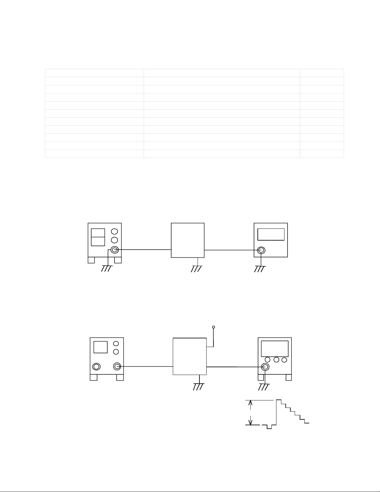
1. VCC2 adjustment
Power supply
Set Digital multimeter
Input Output
CP120
CP102
1) Adjust the output voltage of power supply so that CP120 voltage becomes 11.5 ± 0.05V.
2) Adjust VR102 so that CP102 voltage becomes 5.0 ± 0.02V.
2. Contrast adjustment
GND
SGVideo Signal Oscilloscope
Set
CP313
Video
Input
Output
CP310
1)Ground CP313
2)Apply 75% color bar signal to video input of the set.
3)Observe CP310 signal with an oscilloscope. Adjust VR310 so that
0.6 ± 0.1Vp-p
the amplitude between pedestal and white level is 0.6 ± 0.1Vp-p.
— 2 —
Page 5
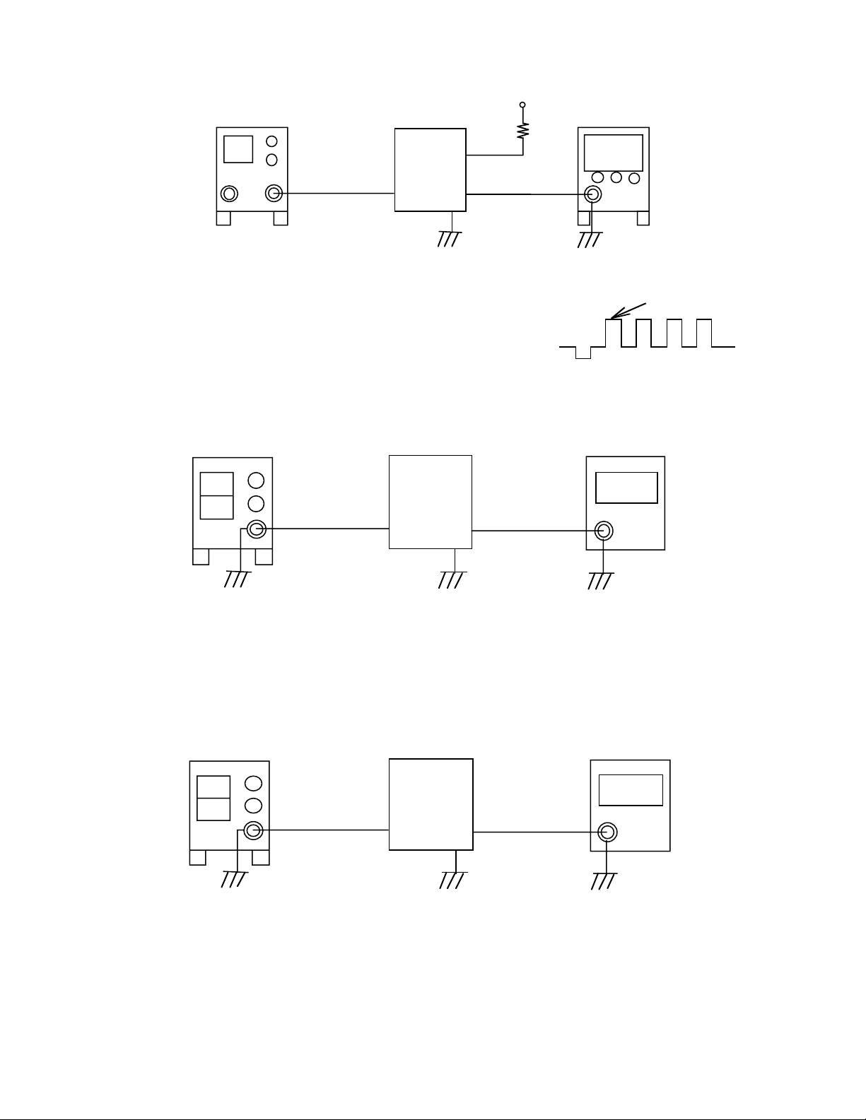
3. Tint/Color adjustment
Video signal Oscilloscope
Set
CP313
Video
Input
1)Ground CP313 via 33k ohm resistor.
2)Unsolder (open circuit) IF pad HP200.
3)Apply 75% color bar signal to video input of the set.
4)Observe CP337 signal. Adjust VR300 (TINT) and VR301 (COLOR)
so that the difference between the four pulses is within 0.2V.
4. VCC4-1 adjustment
Output
CP337
GND
33kw
Pulses 2 and 3 are adjusted by TINT
While pulses 1 and 4 are controlled byCOLOR.
1234
Power supply
Input
DC12V
1) Adjust power supply output so that CP172 voltage becomes 11.5 ± 0.05V.
2) Connect a digital multimeter to CP166 and adjust VR161 so that the meter reading is 4.50 ± 0.02V.
5. VCC9 adjustment
Power supply
Input
DC12V
Set + monitor
Output
CP166
Set + monitor
Output
CP163
Digital multimeter
Digital multimeter
1)Adjust power supply voltage so that CP172 voltage becomes 11.5 ± 0.05V.
2)Connect a digital multimeter to CP163 and adjust VR161 so that the meter reading is 8.3 ± 0.3V.
— 3 —
Page 6

6. VCO Free run adjustment
4.0 ± 0.1V
DClevel=0.1 ± 0.5V
Minimize the amplitude.
Power supply
Set + monitor
CP756
CP757(VCC4-2)
Frequency counter
Input
DC12V
Output
CP181
1)Adjust power supply voltage so that CP172 voltage becomes 11.5 ± 0.05V.
2) Connect CP756 and CP757 (VCC4-2).
3) Connect a frequency counter to CP181 and adjust VR751 so that the counter reading is 15.73 ± 0.1kHZ.
7. V-COM coarse adjustment
Power supply
Input
DC12V
Set + monitor
Digital multimeter
Output
CP802
1) Adjust power supply voltage so that CP172 voltage becomes 11.5±0.05V.
2) Connect an oscilloscope to CP802. Observing the oscilloscope, adjust
VR850 so that pulse amplitude is 4.0±0.1V.
3) Adjust VR801so that pulse's "H" level is 0.1 ± 0.5V.
8. V-COM fine adjustment
Photo diode
Pattern generator
Photo sensor amplifier
Input
Video
Set + monitor
1) Adjust power supply so that CP172 voltage become 11.5 ± 0.05V.
2) Apply black raster signal to the set through Video Input terminal and
turn the brightness control dial all the way to the maximum position.
3) Set the adjustment jig on the monitor as shown on the figure above.
4) observe the sensor amplifier output with an oscilloscope. Adjust VR801 so
that 60Hz component becomes minimum.
— 4 —
Page 7

9. Brightness adjustment
Pattern generator
Input
Video
Set + monitor
Output
CP803~CP805
CP802
1) Apply color bar signal to video input terminal.
2) Provide trigger pulse from CP802 to an oscilloscope.
3) Connect the oscilloscope to CP804 terminal. Observing the oscilloscope,
adjust VR805 so that the voltage level between
positive and negative pedestal is 4.0 ± 0.1V.
4) Perform the same adjustment on CP803 with VR800.
5) Perform the same adjustment on CP805 with VR803.
10. Contrast adjustment
Pattern generator
Set + monitor
Oscilloscope
Trigger
4.0 ± 0.1V
Oscilloscope
Input
Video
Output
CP804
CP802
1) Apply color bar signal to video input terminal.
2) Provide a trigger pulse from CP802 to an oscilloscope.
3) Observing CP804 waveform with the oscilloscope, adjust VR804 so that
voltage level between pedestal and white level is 2.7 ± 0.1V.
11. Monostable multivibrator
Pattern generator
Input
Video
Set + monitor
Output
CP181
CP760
Trigger
2.7 ± 0.1V
Oscilloscope
Trigger
1) Apply color bar signal to video input terminal.
2) Connect CP760 to an oscilloscope as a trigger.
3) Observe CP760 and CP181 signals at the same time. Adjust VR750 so that
delay time between the two pulses is 1.0 ± 0.6µsec. (in case of kx-650) and
0.0 ± 0.8µsec. (in case of kx-660).
— 5 —
CP760
CP181
0.1 ± 0.1µ sec
Page 8

3. PRINTED CIRCUIT BOARDS
650A-M-A PCB
— 6 —
Page 9

661B-L PCB (Top View)
NOTE : Parts in the gray areas are not used.
— 7 —
Page 10

661B-L PCB (Bottom View)
NOTE : Parts in the gray areas are not used.
— 8 —
Page 11

4. EXPLODED VIEW
Video unit
S2
S1
S2
1
2
10
9
S3,S4
S3,S4
S3,S4
4
3
S3,S4
6
8
5
— 9 —
7
Page 12

Monitor
1
S1
a
2
3
S1
S1
4
5
S1
6
8
S4
9
10
S2
11
S3
7
12
S2
S5
13
a
— 10 —
Page 13

5.PARTS PRICE LIST
VM-1000
N Item Code No. Parts Name Specification Q Price Code R
N 1 66100341 Name plate AM-K365 K440276A-1 1 AF X
N 2 66112010 Sensor cover AM-K660 K340585-2 1 AL X
3 66111980 Upper case AM-K660 K140268-2 1 AI X
4 66140180 Rating plate BXA-K661 K440824-6 1 AA X
N 5 27251349 TFT-LCD module COD55T5011RN 1 EK C
N 6 66112587 BLM ass'y K240498*1 1 CM B
N 7 38511911 CRT CAS-26L5.5-1 1 BD A
N 8 66140174 PCB-K661B-M ass'y 4 K241153*1 1 DL B
N 9 38311083 Speaker T036S23C4310 1 AY C
N 10 66112000 Lower case AM-K650 K140269-1 1 AU X
11 66100360 Face shoe AM-K635 K340292-1 1 AI X
N 12 66100370 Cable clamp AM-K635 K440210-1 1 AA X
N 13 35021508 Cable connector R41-1571A 1 CG C
N S1 66112110 Tapping screw A-K650 K440850-1 8 AA X
N S2 58612159 Precision tapping screw 4 AA X
N S3 66112120 Precision flathead screw 4 AA X
S4 66307430 PS screw with washer AK-K618 K440305-1 3 AA X
N S5 58609828 Panhead screw with washer A5112 BTN 2X5 BC 1 AA X
N Item Code No. Parts Name Specification Q Price Code R
N 1 66140190 Upper case BXA-K661 K240242-4 1 AX X
N 2 10151423 Car plug cord CP-K953W 1 AZ X
N 3 66140178 PCB -K661B-L ass'y 4 K241152*1 1 DJ B
N 4 66103260 Lower case AT-K636 K240243-1 1 AS X
N 5 66140200 Rating plate BXA-K661 K440390-3 1 AA X
N 6 66140210 Blind A-K661 K441686-1 1 AA X
N 7 66140220 Blind B-K661 K441687-1 1 AB X
N 8 66140230 Blind C-K661 K441688-1 1 AB X
N 9 66101520 Switch blind K635 K440397-1 1 AA X
N 10 66140240 Spacer BXA-K661 K441690-1 1 AB X
N S1 58610003 Precision panhead screw 1 AA X
N S2 58609905 Tapping screw 2.6X5 black 2 AA X
N S3 58609933 Tapping screw 2.6X5 NI 4 AA X
N S4 58610073 Toothed lock washer 3 NI 4 AA X
N Item Code No. Parts Name Specification Q Price Code R
N - 37011139 AV cord YAF11-0745 1 AM X
- 38511883 Car front stand OS-25FT-(D)-M 1 BV X
N - 38512115 Rear stand OS-22R-(D) 1 CR X
N - 66102300 Tape A-K960 K440345-1 1 AH X
Note : Q - Quantity per unit
R - Rank
N - New Parts
Monitor
Tuner
Accessory
- 11 -
Page 14

M PCB
N Item Code No. Parts Name Specification Q Price Code R
Diodes
D170 23901449 Chip schottky diode MA701A-(TX) 1 AC C
D172 71011194 Chip diode MA111-(TX) 1 AA C
N D173 23602940 Chip zener diode MA3180-H(TX) 1 AA C
D174 23901379 Chip schottky diode MA729-(TX) 1 AB C
D176 23901379 Chip schottky diode MA729-(TX) 1 AB C
D178 71011194 Chip diode MA111-(TX) 1 AA C
D179 23601953 Chip zener diode MA3120-M(TX) 1 AA C
D180 23901470 Chip diode MA143A-(TX) 1 AA C
D500 23701211 Led SLR-342VR3F 1 AA C
D750 71011194 Chip diode MA111-(TX) 1 AA C
D800 23901470 Chip diode MA143A-(TX) 1 AA C
D905 71011194 Chip diode MA111-(TX) 1 AA C
D910 71011194 Chip diode MA111-(TX) 1 AA C
Fuse
FU160 36320343 Chip fuse SSFC1AR12A4 1 AH A
ICs
IC160 21142660 Linear IC FA7611M-TE1 1 AS B
IC170 21144816 IC PQ05SZ5U 1 AL B
N IC500 21143388 OP amplifier BA10324AF-T1 1 AD B
IC650 21141750 Linear IC NJM386-M-T1 1 AE B
N IC750 21143794 LSI MSM6780GS-VK-6001 1 AX B
IC751 21051414 IC TC7S04F-TE85L 1 AC B
N IC800 21145474 IC M52338FP-T1 1 AW B
N IC901 21143780 IC TC74HC393AF(TP1) 1 AI B
N IC902 21054109 IC TC7S14F(TE85L) 1 AC B
Inductors
L160 30131673 Choke coil RCH855-181K 1 AD C
N L161 30132387 Choke coil RCH654-102K-C 1 AE C
N L165 30132401 Choke coil RCH855-221K 1 AC C
L171 30131379 Chip inductor LEM4532-101K-TP 1 AB C
L750 30131043 Chip inductor NLC322522-101K-TP 1 AB C
N L751 30131400 Chip inductor LK2125-120K-TP 1 AA C
N L755 30132394 Chip inductor BK2125HM102-T 1 AA C
L760 30131043 Chip inductor NLC322522-101K-TP 1 AB C
L761 30131043 Chip inductor NLC322522-101K-TP 1 AB C
L800 30131379 Chip inductor LEM4532-101K-TP 1 AB C
L801 30131379 Chip inductor LEM4532-101K-TP 1 AB C
L900 30132401 Choke coil RCH855-221K 1 AC C
Transistors
N Q160 22510868 Transistor 2SB1261K-Z-E1 1 AE C
Q161 22520714 Chip transistor 2SD1623S,T-TD 1 AC C
Q163 22510189 Chip transistor 2SB1218A-R(TX) 1 AA C
Q164 22530133 Chip transistor 2SD1819A-R(TX) 1 AA C
Q170 22530133 Chip transistor 2SD1819A-R(TX) 1 AA C
Q171 22591540 Digital transistor DTC144EU-T106 1 AA C
Q500 22530133 Chip transistor 2SD1819A-R(TX) 1 AA C
Q501 22510189 Chip transistor 2SB1218A-R(TX) 1 AA C
N Q502 22591029 Digital transistor DTC114EU-T106 1 AA C
Q750 22510189 Chip transistor 2SB1218A-R(TX) 1 AA C
N Q800 22591106 Chip transistor FMY1-T148 1 AA C
Q902 22591540 Digital transistor DTC144EU-T106 1 AA C
Note : Q - Quantity per unit
R - Rank
N - New Parts
- 12 -
Page 15

N Item Code No. Parts Name Specification Q Price Code R
Q910 22530308 Chip transistor 2SD1119-R(TX) 1 AC C
Q911 22530308 Chip transistor 2SD1119-R(TX) 1 AC C
Q921 22510189 Chip transistor 2SB1218A-R(TX) 1 AA C
Q922 22591540 Digital transistor DTC144EU-T106 1 AA C
Resistor
N R552 10147758 CDS P1201-01 1 AK C
Converter
N T160 30121491 DC/DC converter CST104-004 1 AW B
N T900 30121484 Inverter converter 2348(W95-152) 1 AW B
Thermistor
TM750
27751092 Chip thermistor 157-154-53015-TP 1 AB C
Variable resistors
VR161 27752751 Chip semi-fixed resistor EVN5ESX50B23 1 AB C
VR650 27650616 Volume RK09H11T-10KB 1 AD C
VR751 27752786 Chip semi-fixed resistor EVN5ESX50B53 1 AA C
N VR801 27752793 Chip semi-fixed resistor EVN5ESX50B52 1 AA C
VR804 27752800 Chip semi-fixed resistor EVN5ESX50B24 1 AA C
VR805 27650623 Volume RK09H11T-20KB 1 AD C
VR850 27752758 Chip semi-fixed resistor EVN5ESX50B14 1 AA C
L PCB
N Item Code No. Parts Name Specification Q Price Code R
Diodes
D100 23902436 Chip schottky diode RB050L-40TE25 1 AC C
D102 23901421 Chip schottky diode MA738-(TX) 1 AD C
D105 23602457 Chip zener diode MA3220-L(TX) 1 AA C
D300 23901470 Chip diode MA143A-(TX) 1 AA C
D350 23900455 Chip diode MA142K-(TX) 1 AA C
N D600 23602492 Diode RD9.1EW 1 AB C
D602 23602492 Diode RD9.1EW 1 AB C
D603 23602492 Diode RD9.1EW 1 AB C
D604 23901470 Chip diode MA143A-(TX) 1 AA C
D605 23901470 Chip diode MA143A-(TX) 1 AA C
F310 38501267 Chroma trap TPS3.58MJ 1 AC C
Fuse
FU100 36320469 Fuse PI-251001(F10) 1 AE A
Oscillator
H310 25900427 Crystal oscillator NR-18 1 AH C
ICs
IC100 21142695 IC FA7615M-TE1 1 AT B
IC110 21143773 IC PQ09SZ1U 1 AM B
IC300 21142835 Linear IC M51405AFP-T1 1 AW B
IC314 21143976 IC BA7046F-T1 1 AJ B
IC315 21010618 MOS IC TC7S08F-TE85L 1 AC B
N IC612 21144354 IC NJM2234M-T1 1 AE B
IC613 21144354 IC NJM2234M-T1 1 AE B
N IC615 21143969 IC BA3121F-T1 1 AL B
Jack
N JK301 35019912 Jack JPJ1166-010432 1 AJ B
Inductors
N L100 38411855 Choke coil LHL10NB151K 1 AD C
N L102 30132079 Choke coil RCR-110D-102K 1 AI C
Note : Q - Quantity per unit
R - Rank
N - New Parts
- 13 -
Page 16

N Item Code No. Parts Name Specification Q Price Code R
L310 30130693 Chip inductor MLF2012C150K-TP 1 AB C
N L350 30131015 Chip inductor NLC453232-100K-TP 1 AA C
L600 30130917 Chip inductor NLC322522-100K-TP 1 AB C
Transistors
Q102 22510560 Transistor 2SB1261K 1 AD C
Q104 22520588 Chip transistor 2SC2412K-T146R 1 AA C
Q303 22501162 Chip transistor 2SA1576A-T106R 1 AA C
Q304 22501162 Chip transistor 2SA1576A-T106R 1 AA C
Q305 22501162 Chip transistor 2SA1576A-T106R 1 AA C
Q315 22520637 Chip transistor 2SC4081-T106R 1 AA C
N Q316 22591365 Array transistor FMW1-T148 1 AB C
Q611 79110126 Digital transistor DTA144EUA-T106 1 AA C
Q621 22520637 Chip transistor 2SC4081-T106R 1 AA C
Q622 22520637 Chip transistor 2SC4081-T106R 1 AA C
Switch
N
SW100
34121582 Slide switch HSW1847-01-040 1 AF B
Variable resistors
N VR102 27752821 Chip semi-fixed resistor EVN5ESX50B13 1 AA C
VR300 27752786 Chip semi-fixed resistor EVN5ESX50B53 1 AA C
VR301 27752800 Chip semi-fixed resistor EVN5ESX50B24 1 AA C
VR310 27752800 Chip semi-fixed resistor EVN5ESX50B24 1 AA C
Note : Q - Quantity per unit
R - Rank
N - New Parts
- 14 -
Page 17

6. SCHEMATIC DIAGRAM
Monitor / M PCB
— 15 —
Page 18

Video unit / L PCB (1/2)
NOTE : Parts in the gray areas are not used.
— 16 —
Page 19

Video unit / L PCB (2/2)
NOTE : Parts in the gray areas are not used.
— 17 —
Page 20

CASIO TECHNO CO.,LTD.
Overseas Service Division
Nishi-Shinjuku Kimuraya Bldg. 1F
5-25, Nishi-Shinjuku 7-Chome
Shinjuku-ku, Tokyo 160-0023, Japan
 Loading...