

Page 1
EXTERNAL PRINTER
FEB. 2000
MODEL UP-250
(without price)
TECHNICAL MANUAL
Page 2

1. This document contains confidential, proprietary information of CASIO or its affiliates.
You must keep such information confidential. If the user is a business entity or organization,
you must limit disclosure to those of your employees, agents and contractors who have
a need to know and who are also bound by obligations of confidentiality.
2. On the earlier of (a) termination of your relationship with CASIO, or (b) CASIO’s request,
you must stop using the confidential information. You must then return or destroy the
information, as directed by CASIO.
3. If a court, arbitrator, government agency or the like orders you to disclose any confidential
information, you must immediately notify CASIO. You agree to give CASIO reasonable
cooperation and assistance in resisting disclosure.
4. You may use confidential information only for the purpose of operating or servicing the
products to which the document relates, unless you obtain the prior written consent of CASIO
for some other use.
5. CASIO warrants that it has the right to disclose the confidential information.
CASIO MAKES NO OTHER WARRANTIES CONCERNING THE CONFIDENTIAL
INFORMATION OR ANY OTHER INFORMATION IN THE DOCUMENT, INCLUDING
(WITHOUT LIMITATION) ANY WARRANTY OF TITLE OR NON-INFRINGEMENT.
CASIO has no liability for loss or damage arising from or relating to your use of or
reliance on the information on the document.
6. You may not reproduce, store or transmit the confidential information in any form or by any
means (electronic, mechanical, photocopying, recording, or otherwise) without the prior
written permission of CASIO.
7. Your obligations under this Agreement are in addition to any other legal obligations.
CASIO does not waive any right under this Agreement by failing to exercise it. The laws of
Japan apply to this Agreement.
CONFIDENTIALITY AGREEMENT
BY USING THIS DOCUMENT, YOU AGREE TO ABIDE BY THE TERMS OF THIS
AGREEMENT. PLEASE RETURN THIS DOCUMENT IMMEDIATELY IF YOU DO NOT AGREE
TO THESE TERMS.
Page 3

FCC CLASS A
FCC Compliance Statement
For American Users
This equipment has been tested and found to comply with the limits for a Class A digital device, pursuant to Part 15 of the
FCC Rules. These limits are designed to provide reasonable protection against harmful interference when the equipment
is operated in a commercial environment.
This equipment generates, uses, and can radiate radio frequency energy and, if not installed and used in accordance with
the instruction manual, may cause harmful interference to radio communications. Operation of this equipment in a
residential area is likely to cause harmful interference, in which case the user will be required to correct the interference
at his or her own expense.
WARNING
The connection of a non-shielded printer interface cable to this printer will invalidate the FCC Verification of this device
and may cause interference levels which exceed the limits established by the FCC for this equipment.
You are cautioned that changes or modifications not expressly approved by the party responsible for compliance could void
your authority to operate the equipment.
FOR CANADIAN USERS
This Class A digital apparatus meets all requirements of the Canadian Interference-Causing Equipment Regulations.
Cet appareil numérique de la classe A respecte toutes les exigences du Règlement sur le matériel brouilleur du Canada.
GEREÄUSCHPEGEL
Gemäß der Dritten Verordrung zum Gerätesicherheitsgecsetz (Maschinenlärminformations- Verordnung-3. GSGV) ist der
arbeitsplatzbezogene Geräusch-Emissionswert kleiner als 70 dB(A) (basierend auf ISO 7779).
Page 4

Introduction
PU-250 Series (Type B) printers are one-station printers for ECR and POS use that can print the results of weighing or
measuring. The main features of the PU-250 Series (Type B) printers are the following:
o High-speed printing through logic-seeking control
o Excellent reliability and long life resulting from the use of two stepping motors, one for moving the carriage and one
for paper feeding
o Flexible paper feed setting permits printing in accordance with any user-defined format
o Command protocol based on ESC/POS, a widely used standard
o Built-in drawer kick-out interface provides capability to drive two drawers
o Selectable character fonts (7 x 9, 9 x 9)
o Semi-automatic paper loading capability
o AC adapter (included) provides compact power supply
o Compact and light in weight
o Automatic Status Back (ASB) function to automatically send printer status changes
o Auto-cutter euipped
o Two-color printing: black and red are selectable.
Notes and Cautions
Note:
Notes have important information and useful tips on the operation of your printer.
CAUTION:
Cautions must be observed to avoid damage to your equipment.
Page 5

CONTENTS
Chapter 1 Features and General Specifications ......................................................1
Features .......................................................................................................................... 2
Printing Specifications ........................................................................................................ 2
Character Specifications..................................................................................................... 3
Paper .................................................................................................................................. 4
Auto-cutter .......................................................................................................................... 5
Paper Roll Supply Device................................................................................................... 5
Receive Buffer .................................................................................................................... 5
Electrical Specifications...................................................................................................... 5
Ribbon Cassette .................................................................................................................5
External Dimensions and Weight........................................................................................ 6
Environmental Specifications ............................................................................................. 6
Reliability ............................................................................................................................ 7
Safety Standards ................................................................................................................7
Printer Installation Position ................................................................................................. 7
Hardware Configuration ................................................................................................ 8
Main Unit Specifications ............................................................................................... 9
Paper Feed Motor............................................................................................................... 9
Carriage Motor.................................................................................................................... 9
Print Head Unit ................................................................................................................... 9
Home Position Sensor........................................................................................................ 9
Paper End Detector .......................................................................................................... 10
Paper Roll Near-end Detector (Optional) ......................................................................... 10
Connectors ................................................................................................................... 10
Interface Connector .......................................................................................................... 10
Power Supply Connector...................................................................................................11
Drawer Kick-Out Connector............................................................................................... 11
Interface ........................................................................................................................ 13
RS-232 Serial Interface .................................................................................................... 13
RS-485 Serial Interface (option) ....................................................................................... 16
IEEE 1284 Parallel Interface ............................................................................................ 16
Buttons and Switches ................................................................................................. 19
Power Switch....................................................................................................................19
Panel Button ..................................................................................................................... 19
DIP Switches ....................................................................................................................20
Panel LEDs ................................................................................................................... 22
Self-test......................................................................................................................... 22
Error Processing.......................................................................................................... 23
Printer Operation When an Error Occurs........................................................................... 23
Data Receive Error ............................................................................................................ 23
Buffer Full Printing ...................................................................................................... 23
Detectors and Printing ................................................................................................ 23
Hexadecimal Dump...................................................................................................... 24
Performing a Hexadecimal Dump..................................................................................... 24
Options .........................................................................................................................24
External Power Supply PS-170 ........................................................................................ 25
Page 6

Chapter 2 Mechanism Configuration and Operating Principles...........................26
Printer Mechanism Operating Principles................................................................... 26
Print mechanism unit ........................................................................................................ 27
Print head unit movement................................................................................................. 28
Wire movement when a single dot is printed.................................................................... 28
Printing a character (9x9 font) ......................................................................................... 29
Paper Feed Mechanism Unit ............................................................................................ 30
Paper loading (semi-automatic loading) ........................................................................... 31
Paper feeding ...................................................................................................................31
Ribbon Feed Mechanism Unit .......................................................................................... 32
Ribbon feeding ................................................................................................................. 33
Detection Mechanism Unit................................................................................................ 34
Home position detection mechanism................................................................................ 34
Paper detection mechanism ............................................................................................. 35
Paper roll near-end detection mechanism (optional)........................................................ 35
Auto-cutter mechanism..................................................................................................... 35
Ribbon Switch Mechanism Unit ................................................................................. 36
Switching from Black to Red............................................................................................. 36
Releasing from Red to Black ............................................................................................ 36
Electrical Circuitry Operating Principles ................................................................... 37
Hardware Configuration.................................................................................................... 37
Principles of Operation ............................................................................................... 41
Power Supply Circuitry ..................................................................................................... 41
Control Circuitry................................................................................................................ 42
CPU .................................................................................................................................. 43
Various detector circuits.................................................................................................... 46
Host interface circuit ......................................................................................................... 47
Drawer kick-out drive circuit ............................................................................................. 47
DIP switch read circuit ...................................................................................................... 48
Printer Mechanism Driver Circuits ............................................................................. 50
Print head driver circuit..................................................................................................... 50
Paper feed motor driver circuit ......................................................................................... 51
Carriage motor driver circuit ............................................................................................. 51
Auto-cutter driver circuit.................................................................................................... 52
Chapter 3 Handling and Maintenance .....................................................................53
Handling Precautions .................................................................................................. 53
Storage Precautions ......................................................................................................... 53
Use Precautions ............................................................................................................... 53
Paper Handling Precautions ............................................................................................. 53
Ribbon Cassette Handling Precautions ............................................................................ 54
Replacing the Paper Roll............................................................................................. 54
Replacing the Ribbon Cassette .................................................................................. 57
Removing Jammed Paper ........................................................................................... 60
Using the Power Switch Cover ................................................................................... 64
Inspection and Maintenance....................................................................................... 65
Cleaning........................................................................................................................66
Page 7

Lubricants..................................................................................................................... 66
Standard Lubrication ........................................................................................................ 66
Lubricants ......................................................................................................................... 66
Lubrication Points ............................................................................................................. 67
Tool List ........................................................................................................................ 67
Chapter 4 Troubleshooting ......................................................................................68
Self-test......................................................................................................................... 68
Initiating the Self-test ........................................................................................................68
Self-test Standby .............................................................................................................. 68
Ending the Self-test .......................................................................................................... 68
Troubleshooting Flowchart......................................................................................... 69
Troubleshooting Tables ............................................................................................... 76
Error Types and Countermeasures ............................................................................ 82
Chapter 5 Disassembly, Assembly, and Adjustment .............................................87
Small Part Specifications ............................................................................................ 87
Disassembly ................................................................................................................. 88
Removing the fuse............................................................................................................ 88
Removing the print head unit............................................................................................ 89
Removing the auto-cutter ................................................................................................. 91
Removing the main circuit board assembly ...................................................................... 92
Sub-assembly A ........................................................................................................... 94
Paper feed frame unit assembly ....................................................................................... 94
Main Assembly 1 .......................................................................................................... 98
Ribbon switch lever, ribbon release spring, ribbon release lever,
ribbon intermediate gear, ribbon transmission gear, ribbon take-up assembly,
and ribbon drive plate assembly ....................................................................................... 98
Main Assembly 2 ........................................................................................................ 100
Tension plate assembly .................................................................................................. 100
Main Assembly 3 ........................................................................................................ 100
Paper feed frame assembly ............................................................................................ 100
Main Assembly 4 ........................................................................................................ 101
Carriage motor assembly................................................................................................ 101
Main Assembly 5 ........................................................................................................ 102
Carriage sub assembly................................................................................................... 102
Main Assembly 6 ........................................................................................................ 103
Carriage shaft assembly................................................................................................. 103
Main Assembly 7 ........................................................................................................ 104
Adjustment roller shaft holder assembly......................................................................... 104
Main Assembly 8 ........................................................................................................ 105
Carriage guide shaft assembly ....................................................................................... 105
Main Assembly 9 ........................................................................................................ 105
Belt tension spring assembly.......................................................................................... 105
Page 8

Main Assembly 10 ...................................................................................................... 106
Sensor assembly ............................................................................................................ 106
Main Assembly 11 ...................................................................................................... 108
Carriage motor heat sink assembly ................................................................................ 108
Main Assembly 12 ...................................................................................................... 108
Print head FPC assembly ............................................................................................... 108
Main Assembly 13 ...................................................................................................... 110
Print head unit ................................................................................................................ 110
Main assembly 14....................................................................................................... 111
Left cover fixing plate and right cover fixing plate........................................................... 111
Main Assembly 15 ...................................................................................................... 112
Ribbon frame earth plate ................................................................................................ 112
Main Assembly 16 ...................................................................................................... 113
Ribbon frame assembly , ribbon frame spring, and ribbon frame fixing plate.................. 113
Main Assembly 17 ...................................................................................................... 114
Thumb-screw and head cover ........................................................................................ 114
Main Assembly 1 (Case Unit).................................................................................... 115
Lower cutter plate assembly ........................................................................................... 115
Main Assembly 2 (Case Unit).................................................................................... 116
Upper plate assembly ..................................................................................................... 116
Main Assembly 3 (Case Unit).................................................................................... 118
Main circuit board assembly ........................................................................................... 118
Main Assembly 4 (Case Unit).................................................................................... 119
Inserting the cables ........................................................................................................ 119
Main Assembly 5 (Case Unit).................................................................................... 120
Lower case assembly ..................................................................................................... 120
Main Assembly 6 (Case Unit).................................................................................... 121
Manual cutter assembly and auto-cutter fixing plate ...................................................... 121
Main Assembly 7 (Case Unit).................................................................................... 123
Auto-cutter assembly ...................................................................................................... 123
Main Assembly 8 (Case Unit).................................................................................... 126
Paper roll receive rollers, upper case, guide roller, and switch panel assemblies .......... 126
Main Assembly 9 (Case Unit).................................................................................... 128
Interface circuit board assembly and connector plate .................................................... 128
Main Assembly 10 (Case Unit).................................................................................. 130
Lower plate, ROM cover, and rubber foot assembly....................................................... 130
Main Assembly 11 (Case Unit) .................................................................................. 131
Main cover assembly ...................................................................................................... 131
Main Assembly 12 (Case Unit).................................................................................. 132
Near-end detector assembly (optional)........................................................................... 132
Adjustment ................................................................................................................. 134
Platen gap adjustment.................................................................................................... 134
Page 9

Appendix....................................................................................................................135
RS-485 Serial Interface .............................................................................................. 135
Main Circuit Board Parts Layout .............................................................................. 140
RS-232 Serial Interface Circuit Board Parts Layout ............................................... 141
IEEE 1284 Parallel Interface Circuit Board Parts Layout ....................................... 142
RS-485 Serial Interface Circuit Board Parts Layout ............................................... 143
Main Circuit Board Diagram...................................................................................... 144
RS-232 Serial Interface Circuit Board Diagram....................................................... 145
IEEE 1284 Parallel Interface Circuit Board Diagram............................................... 146
RS-485 Serial Interface Circuit Board Diagram....................................................... 147
Printer Mechanism Unit Overall Exploded Diagram ............................................... 148
Case Unit Overall Exploded Diagram....................................................................... 149
Printer Mechanism Unit Lubrication Points Diagram............................................. 150
Case Unit Lubrication Points Diagram .................................................................... 151
Parts List....................................................................................................................152
EXPLODED DIAGRAM FOR TM-U200B/U210B NO.1 .............................................154
EXPLODED DIAGRAM FOR TM-U200B/U200PB/U210B/U210PB NO.2 ................155
Page 10
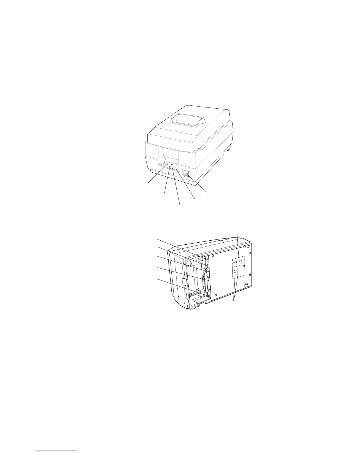
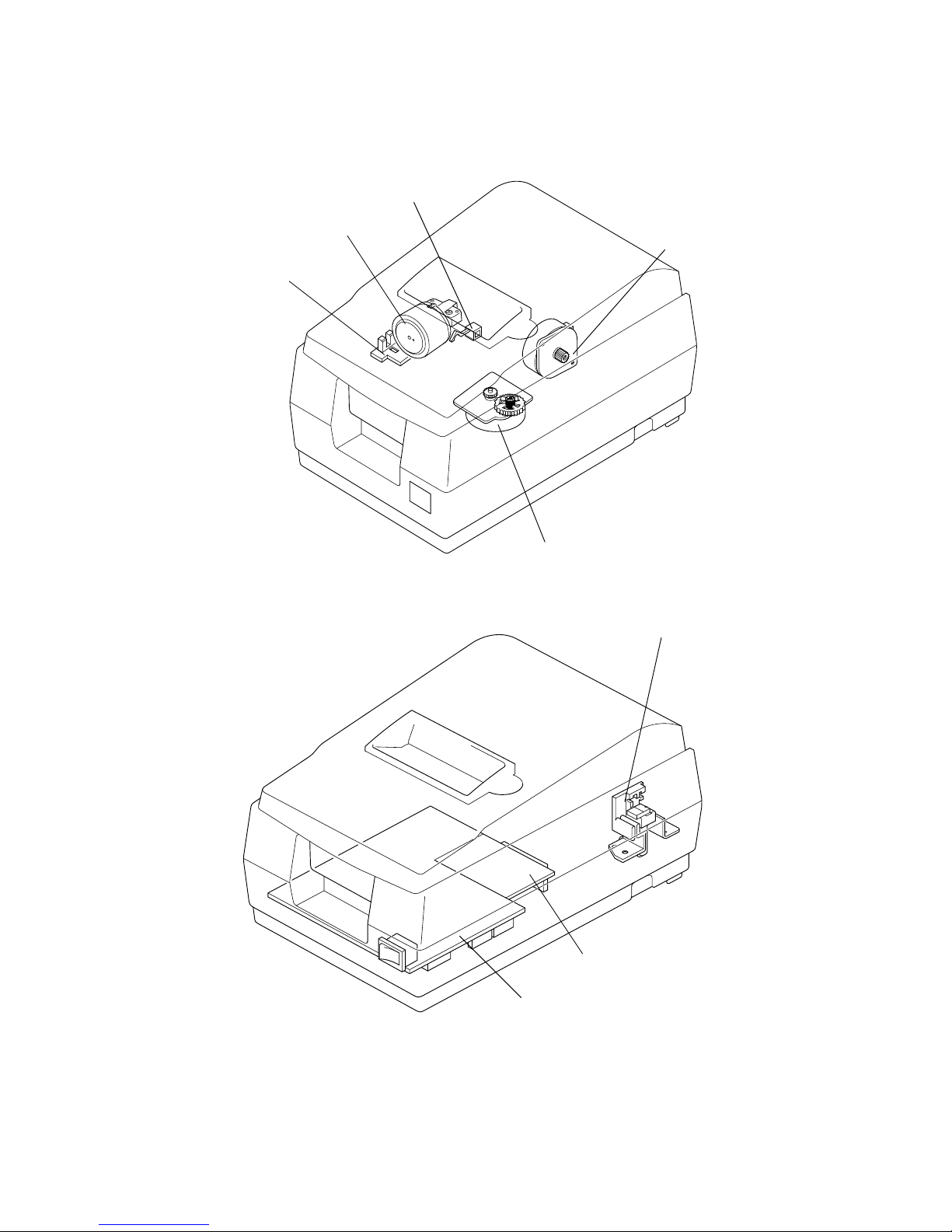
Figure 1-1 PU-250 appearance
POWER LED
Power switch
PAPER OUT LED
ERROR LED
FEED button
(PAPER OUT/PRESS FEED)
PROM
DIP switches
Power supply connector
Drawer kick-out connector
Frame ground screw
Interface connector
Frame ground screw
— 1 —
Chapter 1
Features and General Specifications
Page 11

Features
Printing Specifications
NOTE:
If the print duty ratio is too high, the operation of the print head is stopped by the duty limit. In
such circumstances, the print speeds shown above cannot be guaranteed.
cpi = characters per inch.
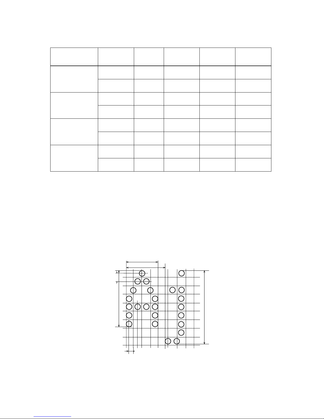
Printing method: Serial impact dot-matrix
Head wire configuration: 9-pin serial type
Figure 1-2 Dot configuration
Dot pitch: 0.353 mm (1/72")
Dot wire diameter 0.29 mm (0.01")
Printing direction: Bidirectional with logic seeking
Printing width: 63.34 mm (2.49")
Line feed: 4.233 mm (1/6"): default setting
Programmable in units of 1/144 inch by using commands.
Paper feed method Friction feed
Paper feed speed: Approximately 4.17 inches/second (25 lines/second) during
continuous paper feeding
Characters per line: See the table on the next page.
Characters per inch: See the table on the next page.
Total dot count (horizontal
direction)
7 x 9 font: 400 half-dot positions per line
9 x 9 font: 400 half-dot positions per line
Print speed Approximately 3.5 lines/second (40 columns, 16 cpi)
Approximately 6.4 lines/second (16 columns, 16 cpi)
0.29 mm (0.01")
(wire diameter)
0.317 mm (0.012")
0.353 mm
(0.014")
— 2 —
Page 12
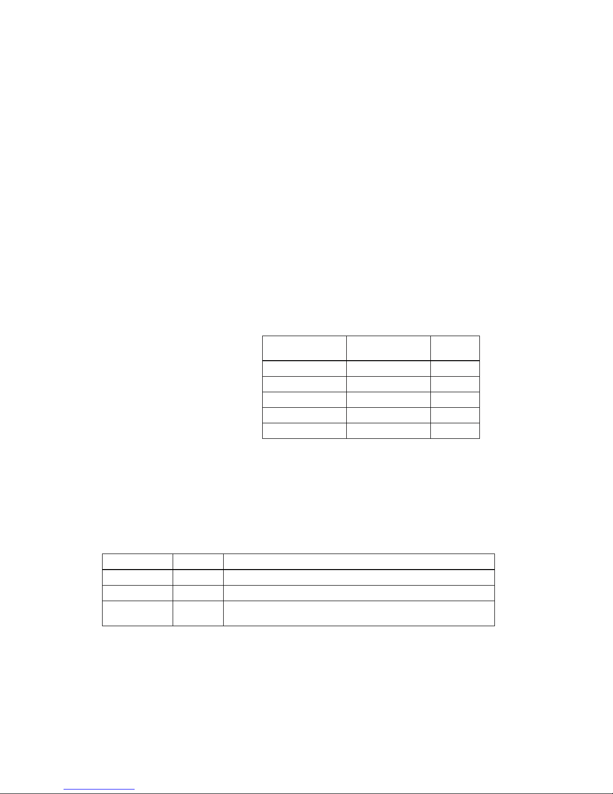
Character dimensions, characters per inch, characters per line
NOTE:
The default font is 7 x 9; the dot spacing between characters is either 3 half dots or 2 half dots,
depending on the setting of DIP switch 2-1.
Character Specifications
Character Structure
Horizontal x Vertical
Character
Structure
Character Set
Character
Dimensions
WxH
Dot Spacing
Between
Characters
Characters Per
Line (cpl)
Characters Per
Inch (cpi)
7 x 9
ANK
1.2 x 3.1 mm
(.047 x .122")
3 half dots 40 16
Graphics
1.7 x 3.1 mm
(.070 x .122")
0 40 16
9 x 9
ANK
1.6 x 3.1 mm
(.063 x .122")
3 half dots 33 13.3
Graphics
2.0 x 3.1 mm
(.079 x .122")
0 33 13.3
7 x 9
ANK
1.2 x 3.1 mm
(.047 x .122")
2 half dots 42 17.8
Graphics
1.6 x 3.1 mm
(.063 x .122")
0 42 17.8
9 x 9
ANK
1.6 x 3.1 mm
(.063 x .122")
2 half dots 35 14.5
Graphics
1.9 x 3.1 mm
(.075 x .122")
0 35 14.5
Character sets: Alphanumeric: 95
International: 32
Graphics: 128 x 8 pages
Character structure: 7 x 9 with 400 half-dot positions per line
9 x 9 with 400 half-dot positions per line
Figure 1-3 Character size (7 x 9 font example)
3.1 mm
(0.122")
2.4 mm
(0.094")
1. 24 m m (0 .049" )
1.59 m m (0.0 63")
0.159 mm (0.006")
0.353 mm
(0.014")
— 3 —
Page 13
Paper
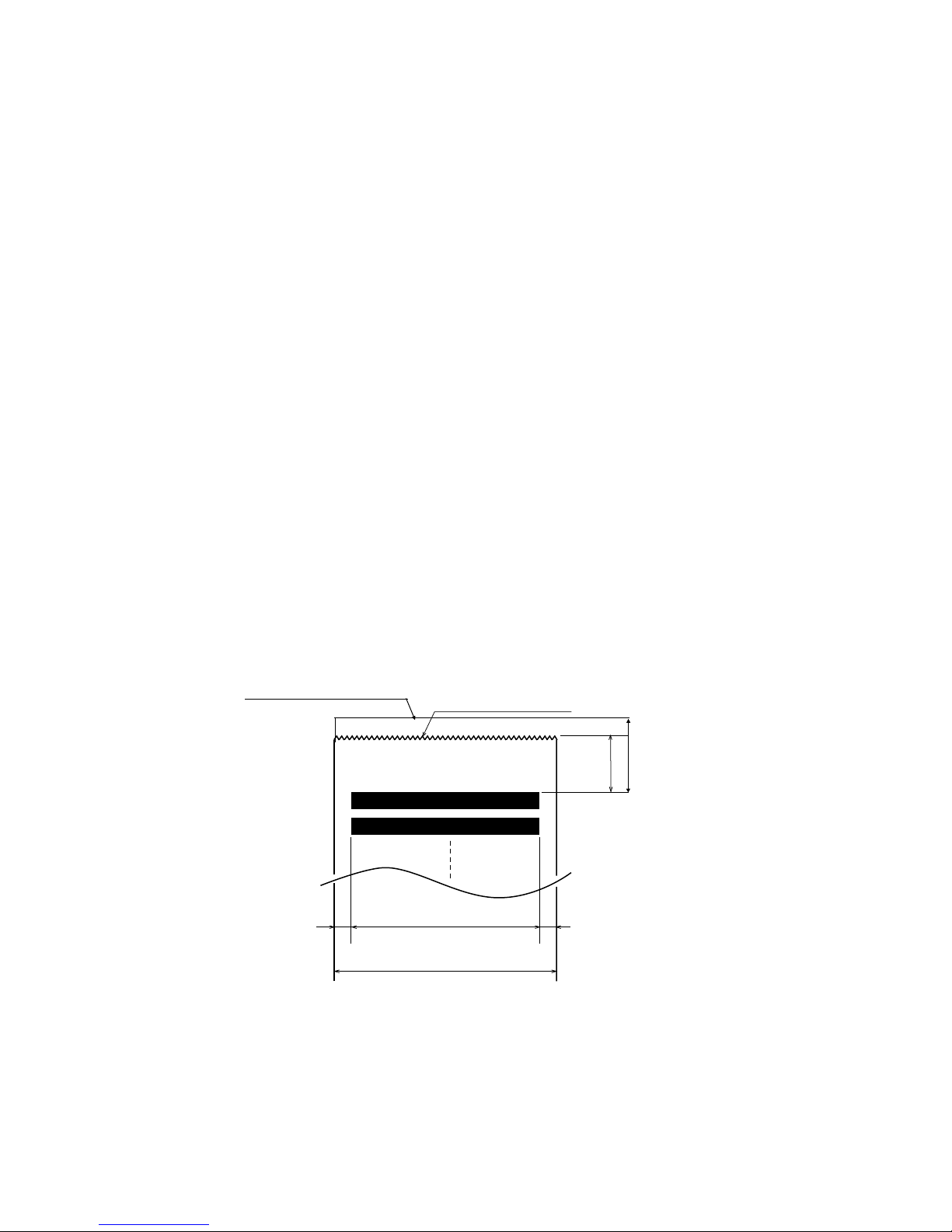
(*1)
This dimension shows the distance from the manual cutter to the print position.
(*2)
Values fo r the p rin ting are a are calcul ated (between dot cen ters) wit h the wi re diameter (0.29 m m [.011 "]).
Paper types: Paper roll: Plain paper or pressure-sensitive paper
Paper roll width: 76 ± 0.5 mm (2.99 ± .020")
Paper roll maximum
diameter:
83 mm (3.27")
Paper roll core: Unless there is an optional near-end detector, you cannot use a paper
roll with the core and paper glued together.
Normal paper: Thickness: 1 sheet: 0.06 to 0.085 mm (.0024 to .0034")
Weight: 52.3 to 64 g/m
2
(13.9 to 17 lb)
(45 to 55 kg/1000 sheets/1091 x 788)
Pressure-sensitive paper Original sheet + up to 1 copy sheet
Thickness: 1 sheet: 0.05 to 0.08 mm (.0020 to .0031")
Total thickness: 0.2 mm (.0079") or less
Recommended paper: Mitsubishi - carbonless paper (blue)
Top and middle sheets: N40Hi
paper thickness: 0.06 mm (.0024")
weight: 47.2 g/m
2
(12.6 lb)
Bottom sheet: N60
paper thickness: 0.08 mm (.0031")
weight: 68.0 g/m
2
(18.1 lb)
Figure 1-4 Printing area
Maximum of 200 dots, 400 positions
76 mm (2.99")
20.2 mm (0.79") (*1)
Cutting position (manual cutter)
(*2)
63.34 mm (2.49")
[5.9 mm (0.23")] [6.76 mm (0.27")]
Cutting position (auto-cutter)
27 mm (1.063")
— 4 —
Page 14
Auto Cutter
Partial cut is executed by a command. (A partial cut leaves one point uncut.)
Paper Roll Supply Device
Receive Buffer
Either 1KB or 40 bytes, selectable by DIP switches.
Electrical Specifications
Ribbon Cassette
Ribbon cassette specifications
(*1)
Ribbon life is based on the following conditions:
Character font: 7 x 9 font (with descenders)
Print pattern: ASCII 96-character rolling pattern. See the specification published by EPSON for the print
pattern example.
NOTE:
Malfunctions and other problems may occur if a ribbon cassette other than the specified one is used.
Supply device: Drop-in loading
Power supply One of the following five AC adapters is included, depending on
the specifications:
AC adapter specifications
Power consumption
(except when driving
drawer kick-out):
Operating: Mean average 43 W
Standby: Average 6 W
Model number Color Ribbon life (*1)
ERC-38 (P) Purple 4 million characters (with continuous printing at 25° C [77° F])
ERC-38 (B) Black 3 million characters (with continuous printing at 25° C [77° F])
ERC-38 (B/R)
Black and
Red
Black: 1.5 million characters (with continuous printing at 25° C [77° F])
Red: 750,000 characters (with continuous printing at 25° C [77° F])
Settings and
shipment
Input voltage range
Model
name
Japan 100 V ± 10%, 50/60 Hz PA-6508
North America 120 V ± 10%, 60 Hz PB-6509
Europe (Germany) 230 V ± 10%, 50 Hz PB-6510
Europe (U.K.) 230 V ± 10%, 50 Hz PA-6511
Australia 240 V ± 10%, 50 Hz PA-6513
— 5 —
Page 15
External Dimensions and Weight
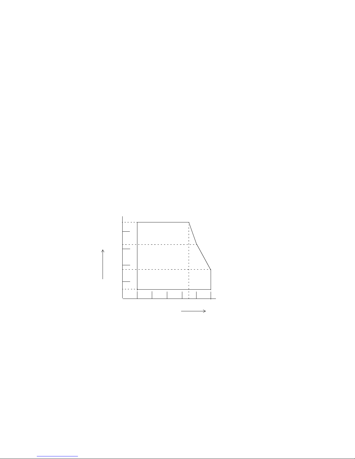
Environmental Specifications
Height: 150 mm (5.91")
Width: 160 mm (6.30")
Depth: 248 mm (9.76")
Weight: Approximately 2.5 kg (5.5 lb)
Color: EPSON standard gray
Temperature: Operating: 0° to 50° C (32° to 122° F)
At 34° C (93° F) or higher, there are humidity restrictions;
see the figure below.
Storage: –10° to 50° C (14° to 122° F), except paper and ribbon
Humidity: Operating: 10% to 90% RH (non-condensing)
Storage: 10% to 90% RH (non-condensing), except paper and ribbon
Figure 1-5 Operating temperature and humidity range
Vibration resistance: When packed:
Frequency: 5 to 55 Hz
Acceleration: 2 G
Sweep: 10 minutes (half cycle)
Duration: 1 hour
Directions: x, y, and z
Operating Temperature Range
40° C (104° F), 65%
34° C (93° F), 90%
50° C (122° F), 35%
80
60
40
20
0
0 10 40
Environmental Temperature
Relative Humidity [% RH]
50
90
10
3020
— 6 —
Page 16

Reliability
Safety Standards
The following standards are applied only to the printers that are so labeled.
Printer Installation Position
Install the printer horizontally. Make sure it does not tilt more than 15°. The printer must also be installed
so that it does not move or vibrate during paper cutting or the drawer kick-out operation. Fastening tape
is available as an option.
Impact resistance: When packed:
Package: EPSON standard package
Height: 60 cm (23.62")
Directions: 1 corner, 3 edges, and 6 surfaces
When unpacked:
Height: 5 cm (1.97")
Directions: Lift one edge and release it (for all 4 edges)
Life
Mechanism: 7,500,000 lines (See the UP-250) Specification for the print color
switching number.
Print head: 150 million characters (using an average of 2 dots/wire per character.)
(The print pattern is shown in the UP-250 Specification in Figure A-1.)
Auto cutter: 800,000 cuts
End of life is defined as the point at which the printer reaches the
beginning of the wear out period.
MTBF 180,000 hours
Failure is defined as a random failure occurring within the time of the
random failure period.
MCBF 18,000,000 lines
This is an average failure interval based on failures relating to wear out
and random failures up to the life of 7,500,000 lines.
For Europe: CE Marking: EN55022, EN50082-1, EN45501
Safety standards: TÜV
EMI: FCC class A
For USA:
Safety standards: UL1950-2TH-D3
c-UL
— 7 —
Page 17
Hardware Configuration
Figure 1-6 UP-250 main unit configuration
Carriage motor
Paper feed motor
Paper end detector
Print head unit
Home position sensor
Paper roll near-end detector (optional)
Main circuit board
Interface circuit board
— 8 —
Page 18

Type: 4-phase, 48-polarity, PM-type stepping motor
Drive voltage: 24 VDC ± 10%
Winding resistance: 58 Ω ± 2.9 Ω at 25°C (77°F), per phase
Current consumption: Peak: 1.1 A in worst case
Average: 200 mA at 24 VDC, 25°C (77°F), 600 pps
350 mA maximum
Type: 4-phase, 48-polarity, PM-type stepping motor
Drive voltage: 24 VDC ± 10%
Winding resistance: 39.5 Ω ± 1.9 Ω at 25°C (77°F), per phase
Current consumption: Peak: 1.5 A maximum
Average: 400 mA at 24 VDC, 25°C (77°F), 952 pps
600 mA maximum
Number of solenoids: 9
Winding resistance: 19.2 Ω ± 5% at 25°C (77°F), per phase
Drive voltage: 24 VDC ± 10%
Type: Photo sensor
Voltage: 5 VDC ± 5%
Output level: LOW when the carriage home position is detected
— 9 —
Main Unit Specifications
Paper Feed Motor
Carriage Motor
Print Head Unit
Home Position Sensor
Page 19
Paper End Detector
Paper Roll Near-end Detector (Optional)
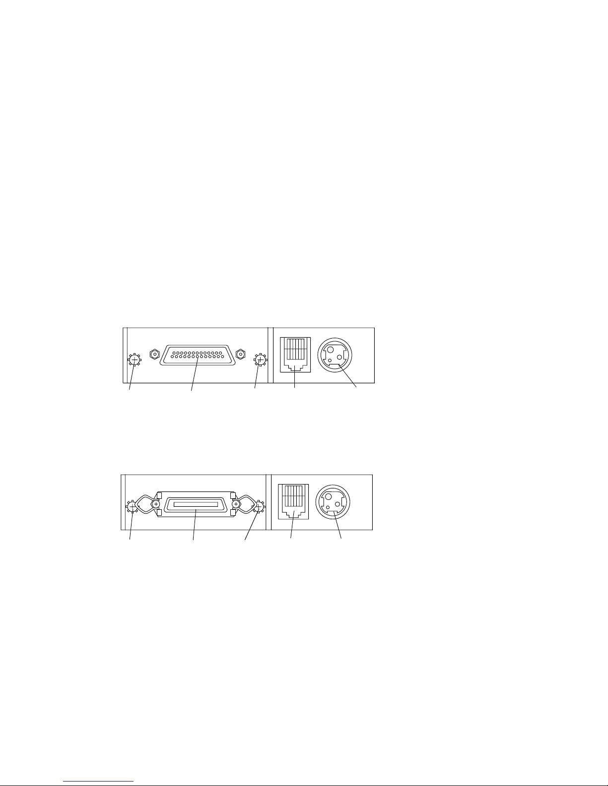
Connectors
Figure 1-7 Connector panel (serial interface)
Figure 1-8 Connector panel (parallel interface)
Interface Connector
See the interface section.
Type: Microswitch
Voltage: 5 VDC ± 5%
Output level: High when paper end is detected
Type: Microswitch
Voltage: 5 VDC ± 5%
Output level: Low when a paper near-end is detected
Frame ground
screw connector
Power supplyDrawer kick-out
connector
Interface
connector
Frame ground
screw
Power supply
connector
Drawer kick-out
connector
Frame ground
screw
Interface
connector
Frame ground
screw
— 10 —
Page 20
— 11 —
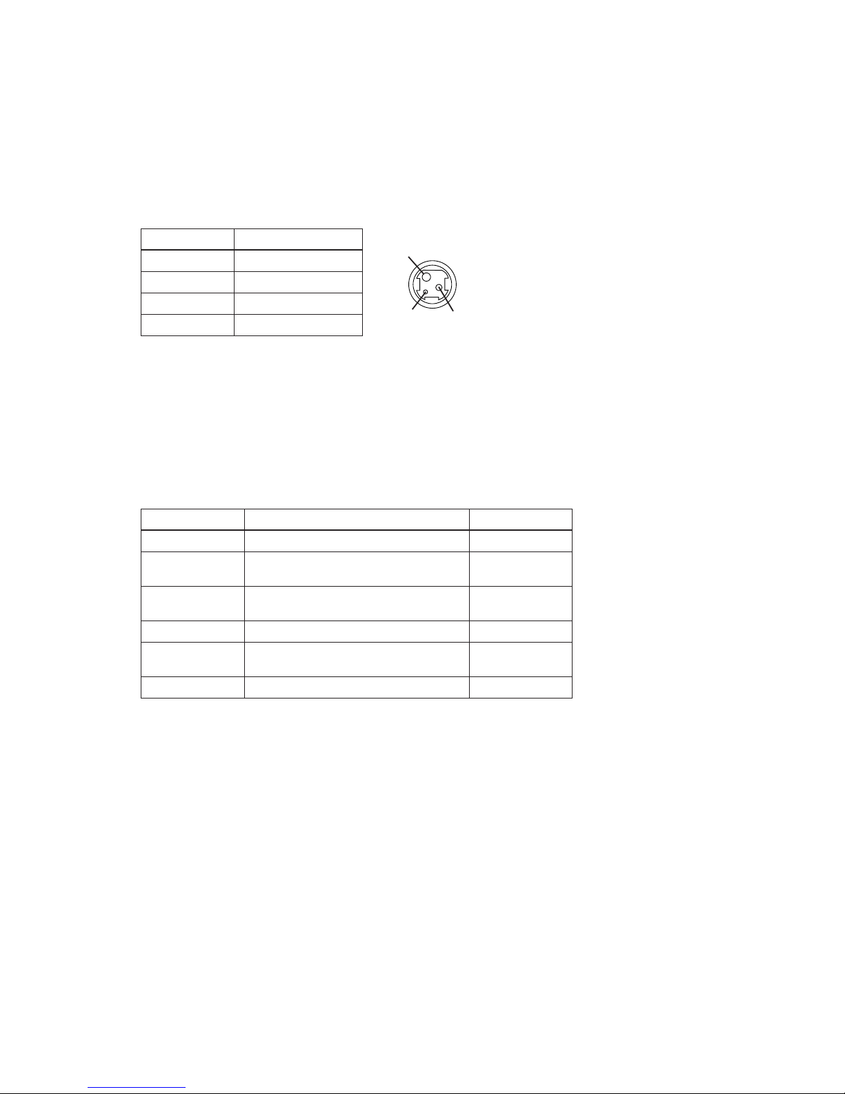
This connector is used to connect the printer to an external power source.
NOTE:
Be sure to ground the frame ground (FG) screw on the board at the bottom of the unit. Ground
wire terminal hole diameter: 3.2 mm (.13"). Ground wire thickness: AWG 18 or equivalent.
A pulse specified by the
ESC p
command is output to the drawer kick-out connector. The host
can confirm the status of the input signal by using the
GS a
,
GS r
, or
DLE EOT
commands.
The host computer can check the drawer open/closed status with the
DLE EOT, GS a
, and
GS r
commands.
Pin assignments: See the table below.
Pin Number
1 + power supply
2 GND
3NC
Shell Frame GND
Pin Number Signal name Direction
1 Frame GND
2
Drawer kick-out drive signal 1
(See "Drawer kick-out drive signal," below.)
Output
3
Drawer open/close signal
(See "Drawer open/closed signal," below.)
Input
4 +24
—
—VDC
5
Drawer kick-out drive signal 2
(See "Drawer kick-out drive signal," below.)
Output
6 Signal GND —
Input signal level: LOW = 0 V
HIGH = 2 to 5 V (at connector pin 3)
2
3 1
Signal Name
Power Supply Connector
Drawer Kick-Out Connector
Power supply connector pin assignments
Drawer kick-out connector pin assignments
Drawer open/closed signal
Page 21
NOTES:
❏
Two driver transistors cannot be energized simultaneously.
❏
The drawer drive duty must be as shown below:
❏
Be sure to use the printer power supply (connector pin 4) for the drawer power source.
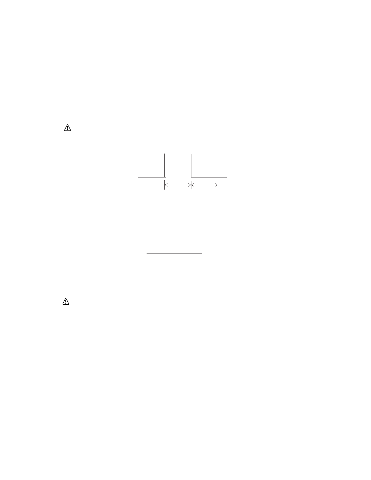
Output signal: Voltage = Approximately 24 VDC
Current = 1 A or less
Output waveform: Outputs the waveforms in Figure 1-8 to pins
2 and 5 of the connector.
t
1 (ON time) and t2
(OFF time) are specified by
ESC p
.
t
1 x 2 ms
t
2 x 2 ms
ON time
(ON time + OFF time)
≤ 0.2
— 12 —
Drawer kick-out drive signal
CAUTION:
To avoid overcurrent, resistance of the drawer kick-out solenoid must be 24 Ω or more.
Figure 1-9 Drawer kick-out drive signal output waveform
CAUTION:
Do not connect a telephone line to the drawer kick-out connector; otherwise the printer and the telephone
line may be damaged.
Page 22

Interface
RS-232 Serial Interface
NOTES:
❏
Handshaking, data word length, baud rate, and parity depend on DIP switch settings.
❏
Data transmitted from the printer has 1 stop bit (fixed).
Data transmission: Serial (compatible with RS-232)
Synchronization: Asynchronous
Handshaking: DTR/DSR or XON/XOFF control
Signal levels: MARK = -3 to -15 V: Logic 1/OFF
SPACE = +3 to +15 V: Logic 0/ON
Baud rates: 4800, 9600 bps
Data word length: 7 or 8 bits
Parity settings: None, even, odd
Stop bits: 1 or more
Connector: Female D-SUB 25-pin connector or equivalent
— 13 —
Page 23
NOTES:
❏
When the remaining space in the receive buffer is 16 bytes, the printer buffer becomes full.
This status continues until the space in the receive buffer increases to 32 bytes.
❏
The printer ignores data received when the remaining space in the receive buffer is 0 bytes.
❏
XON is not transmitted when the receive buffer is full.
Pin number Signal name I/O Function
1 FG — Frame ground
2 TXD O Transmit data
3 RXD I Receive data
4 RTS O Same as the DTR signal
6 DSR I This signal indicates whether the host computer can receive data. SPACE
indicates the host computer can receive data, and MARK indicates the host
computer cannot receive data. When DTR/DSR control is selected, the printer
transmits data after confirming this signal (except when transmitting data by
DLE
EOT
and
GS a
). When XON/XOFF control is selected, the printer does not check
this signal. Changing the DIP switch setting lets this signal be used as a reset
signal for the printer. The printer is reset when the signal remains MARK for
1 ms or more.
7 SG — Signal ground
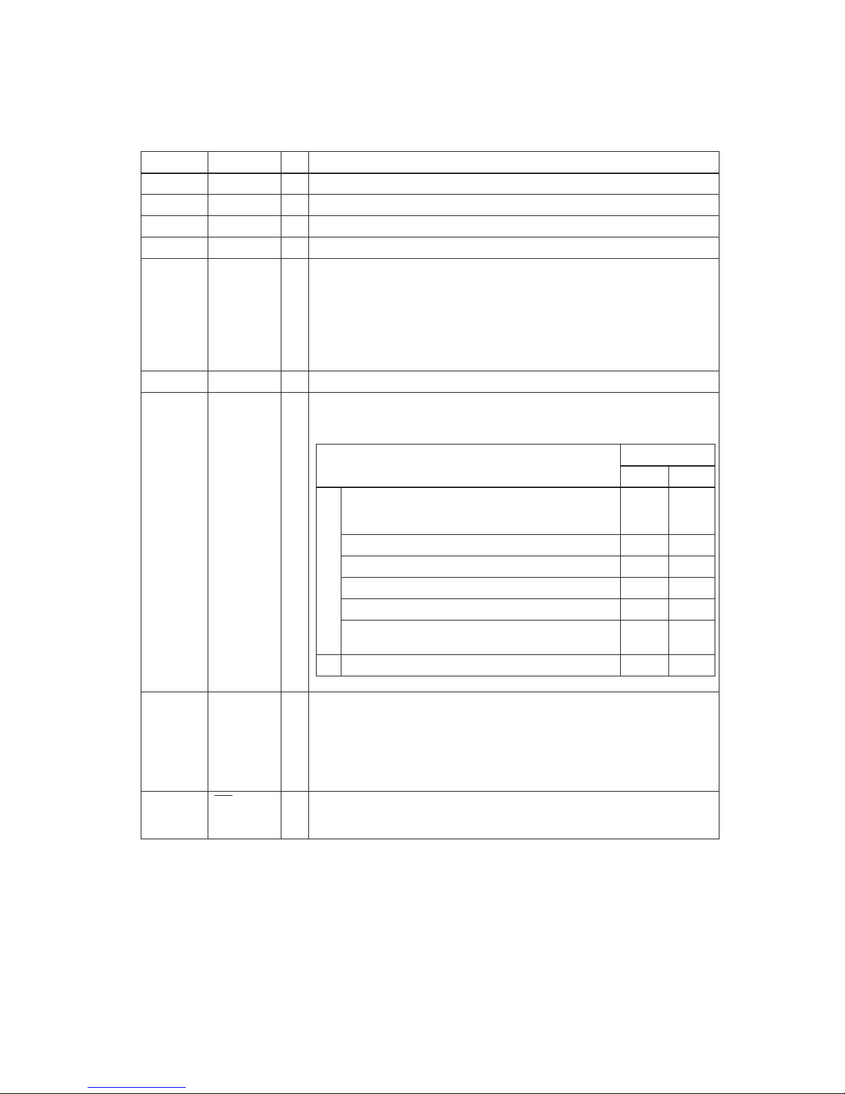
20 DTR O 1) When DTR/DSR control is selected, this signal indicates whether the printer is
busy. SPACE indicates the printer is ready to receive data, and MARK indicates
the printer is busy. A busy condition can be changed using DIP SW 1-8 as follows:
2) When XON/XOFF control is selected:
This signal indicates whether the printer is correctly connected and ready to
receive data. SPACE indicates the printer is ready to receive data. The signal is
always SPACE except in the following cases:
❏
During the period after power on until the printer is ready to receive data.
❏
During self test.
25 INIT
I Changing DIP switch setting enables this signal to be used as a reset signal for
the printer (see the DIP switch settings in the “Buttons and Switches” section of
this chapter). The printer is reset when the signal remains SPACE for 1 ms or more.
Printer
DIP SW 1-8 status
ON OFF
1. During the period from when power is turned on
(including reset using the interface) to when the
printer is ready to receive data.
BUSY BUSY
2. During self-test BUSY BUSY
3. During paper feeding using the paper FEED button — BUSY
4. When the printer stops printing for a paper-end. — BUSY
5. When an error has occurred. — BUSY
6. When a temporary abnormality occurs in the
power supply voltage
— BUSY
7. When the receive buffer becomes full. (See Notes.) BUSY BUSY
Off line
20 DTR
RS-232 interface connector pin assignments and functions
Interface Connector Pin Assignments
— 14 —
Page 24

Switching between on line and off line
The printer does not have an on-line/off-line button. It goes off line under the following
conditions:
❏
Between the time when power is turned on (including reset using the interface) and when
the printer is ready to receive data.
❏
During the self-test.
❏
During paper feeding using the paper
FEED
button.
❏
Between the time when the printer stops printing for a paper-end and when the on-line
recovery wait time finishes after loading paper (if an empty paper supply is detected by
either the paper roll end detector or the paper roll near-end detector with a printing halt
feature enabled for low paper by
ESC c 4
).
❏
When an error has occurred.
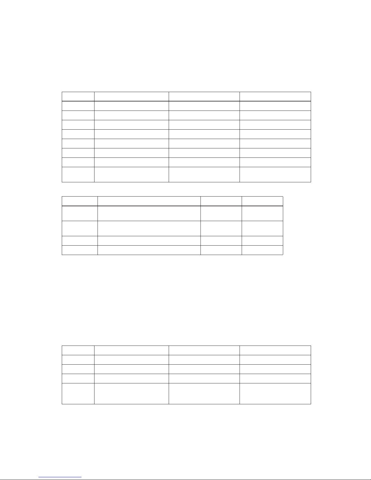
XON/XOFF transmission timing
When XON/XOFF control is selected, the printer transmits XON or XOFF signals as follows.
(
*1) XON is not transmitted when the receive buffer is full.
(*2) XOFF is not transmitted when the receive buffer is full.
NOTE:
The XON code is 11H and the XOFF code is 13H.
Printer status
DIP SW 1-8 status
ON OFF
XON
transmission
• When the printer goes on line after turning power on or after
reset using the interface.
• When the receive buffer is released from the buffer full state.
• When the printer switches from off line to on line (*1).
• When the printer recovers from an error through a command.
Transmission
Transmission
----
----
Transmission
Transmission
Transmission
Transmission
Transmission
Transmission
XOFF
transmission
• During an error condition.
• When the receive buffer becomes full (*2).
Transmission
----
Transmission
Transmission
Serial interface connection example
NOTES:
❏
Set handshaking so that transmitted data can be received.
❏
Transmit data to the printer after turning on the power and initializing the printer.
Host
Printer
TXD
DSR
CTS
RXD
DTR
FG
SG
RXD
DTR
RTS
TXD
DSR
FG
SG
— 15 —
Page 25

RS-485 Serial Interface (option)
Refer to the Appendix for details.
IEEE 1284 Parallel Interface
Complies with the standard described in t he IEEE 12 84 specificat ion by the I nstitute o f Electr ical
and Electronic Engineers, Inc.
Specification
Data transmission: 8-bit parallel
Synchronization: Externally supplied STRO BE
signals
Handshaking:
and BUSY signals
Signal levels: TTL-compatible
Connector: 57RE-40360-830B (DDK) or equivalent (IEEE 1284 Type B)
Reverse communication
(Printer to host): Nibble or byte mode
Reverse Mode (Data Transmission from Printer to Host)
Status data transmission from the printer to the host occurs in nibbl e or byte mode. These modes
allow data transmission from the asynchronous printer under control of the host. Data
transmissions in nibble mode are made via the existing control lines in u nits of four bits (a
nibble). In byte mode, data transmissions proceed by making the eight-bit data lines
bidirectional. Both modes fail to proceed concurrently in compatibility mode, causing half
duplex transmission. The IEEE 1284 nibble/byte modes are under development in draft form
and may be subject to change.
ACK
— 16 —
Page 26

Interface Connector Pin Assignments
IEEE 1284 interface connector pin assignments and functions
NOTES:
❏
❏
❏
❏
❏
❏
Overscored signal names are LOW active signals.
If a host does not provide for the signal lines listed above, two-way communication fails.
For interfacing, signal lines must use twisted pair cables with the return sides connected to signal
ground level.
Interfacing conditions must all be based on the TTL level to meet the characteristics described below.
In addition, both the rise and fall time of each signal must be 0.5 µs or less.
Data transmission must not ignore the ACK or BUSY signal. An attempt to transmit data with either
the ACK or BUSY signal ignored can cause lost data. (Data transmissions to the printer must be made
after verifying the ACK signal or while the BUSY signal is at a LOW level.)
Interface cables should be as short in length as possible.
NC: Not Connected
ND: Not Defined
— 17 —
Pin number Source Compatibility Mode Nibble Mode Byte Mode
1 Host Strobe
Host Clk Host Clk
2 Host/Ptr Data0 (LSB) Data0 (LSB) Data0 (LSB)
3 Host/Ptr Data1 Data1 Data1
4 Host/Ptr Data2 Data2 Data2
5 Host/Ptr Data3 Data3 Data3
6 Host/Ptr Data4 Data4 Data4
7 Host/Ptr Data5 Data5 Data5
8 Host/Ptr Data6 Data6 Data6
9 Host/Ptr Data7 (MSB) Data7 (MSB) Data7 (MSB)
10 Printer Ack
PtrClk PtrClk
11 Printer Busy PtrBusy/Data3,7 PtrBusy
12 Printer PError
AckDataReq/
Data2,6
AckDataReq
13 Printer Select Xflag/Data1,5 Xflag
14 Hostr AutoFd
HostBusy HostBusy
15 NC ND ND
16 GND GND GND
17 FG FG FG
18 Printer Logic-H Logic-H Logic-H
19-30 GND GND GND
31 Host Init
Init Init
32 Printer Fault DataAvail /Data0, 4 DataAvail
33 GND ND ND
34 Printer DK_STATUS ND ND
35 Printer +5V ND ND
36 Host SelectIn
1284-Active 1284-Active
Page 27

Reception of status from the printer through the bidirectional parallel interface
In bidirectional parallel interface operation, printer status transmission is available using the
two-way communication facility of the IEEE 1284-compatible nibble/byte modes. In this case,
unlike in RS-232 serial interface operation, real-time interruptions from the printer to the host
are disabled, and so you must pay attention to the following.
❏
The maximum capacity of the printer’s internal buffer is 100 bytes (except ASB status).
Status signals exceeding this capacity are discarded. To prevent possible loss of status, the
host must be ready for data reception (Reverse Mode).
❏
When ASB is used, the host is preferably in the wait state for data reception (Reverse Idle
Mode). When this state is not available, the host enters Reverse Mode to continually monitor
data presence.
❏
When ASB is used, preference is given to ASB status for transmission over other status
signals. Any accumulated ASB status signals left for transmission from the last to the newest
ASB status transmissions are transmitted together at one time as one ASB status showing the
presence of change, followed by the latest ASB status.
Example: In the normal (wait) state, the ASB status is configured as follows:
In a sequence of operations including near end detection and the paper FEED button being pressed
and released, the following pieces of data are accumulated.
When ASB status is received following this, a total of eight (8) bytes of ASB will be transmitted as follows:
Accumulated ASB (
➀+➁+➂).
First Status Second Status Third Status Fourth Status
0001 0000 0000 0000 0000 0000 0000 0000
First Status Second Status Third Status Fourth Status
➀
0001 0000 0000 0000 0000 0011 0000 0000
Near end
detection.
➁
0101 1000 0000 0000 0000 0011 0000 0000
Paper FEED
button is
pressed.
➂
0001 0000 0000 0000 0000 0011 0000 0000
Paper FEED
button is
released.
First Status Second Status Third Status Fourth Status
Accumulated ASB (
➀+ ➁+ ➂
) 0101 1000 0000 0000 0000 0011 0000 0000
+ First Status Second Status Third Status Fourth Status
The latest ASB (➂)
Fourth Status
0001 0000 0000 0000 0000 0011 0000 0000
— 18 —
Page 28

Notes on setting DIP switch 1-8 to ON
The printer mechanism stops but does not become busy when an error occurs, printing stops for
a paper end, or paper is fed using the FEED button.
When setting DIP switch 1-8 to ON to enable handshaking with the printer, be sure to check the
printer status with
GS a
and ASB function. In this setting, the default value of
n
for
GS a
is 2.
The printer automatically transmits the printer status, depending on on-line/off-line changes.
When using
DLE EOT
and
DLE ENQ
, be sure that the receive buffer does not become full.
❏
If the host cannot transmit data when the printer is busy or if an error occurs,
DLE EOT
and
DLE ENQ
cannot be used when printer is busy because the receive buffer has become full.
❏
With a host that can transmit data when the printer is busy, if the printer’s receive buffer
becomes full while the host is sending bit-image data, a
DLE EOT
or
DLE ENQ
command
transmitted during sending of bit-image data is processed as bit-image data, not as a
command. Secondly, any data transmitted when the receive buffer is full may be lost.
Example: Check printer status using
GS r
after transmitting each line of data and use the 1KB
receive buffer. Transmit one line of data so that the receive buffer does not become full.
Buttons and Switches
Power Switch
Note:
Turn on the power only after connecting the power supply.
Panel Button
The panel button is enabled or disabled by the
ESC c 5
command. This button is inactive if it is
disabled.
Note:
The
ESC c 5
command enables or disables the panel button. When disabled, the button does not
function. However, when loading a paper roll, you can feed paper with the
FEED
button during the
paper loading waiting time if the paper loading waiting time is set by
GS z 0
. Press the
FEED
button
again after the
PAPER OUT LED
starts blinking to return the printer to the on-line state.
Type: Rocker switch
Function: The power switch turns the power on or off.
Feed
(FEED
) button: Type: Non-locking push button
Function: Feeds paper based on the line feed amount set by
ESC 2
and
ESC 3
.
— 19 —
Page 29
DIP Switches
Serial interface (RS-232 and RS-485 (option))
The DIP switches are located at the bottom of the case.
NOTES:
❏
Do not change the setting of DIP switch 2-2 (fixed to ON).
❏
Changes in DIP switch settings (excluding switches 2-3 and 2-4, which are I/F reset signals) are
recognized only when printer power is turned on or reset using the interface. If the DIP switch setting
is changed after printer power is turned on, the change does not take effect until the printer is turned
on again or reset.
Parallel interface (IEEE 1284)
The DIP switches are located at the bottom of the case.
DIP switch 1
DIP Switch Function ON OFF
1 Data receive error Ignored Prints “?”
2 Receive buffer capacity Data buffer 40 bytes Data buffer 1KB
3 Handshaking XON/XOFF DTR/DSR
4 Data word length 7 bits 8 bits
5 Parity check Yes No
6 Parity selection Even Odd
7 Baud rate selection 4800 bps 9600 bps
8 Busy condition When the receive buffer is full
When the receive buffer is full
in off-line status
DIP switch 2
DIP Switch Function ON OFF
1
Print column selection
7 ✕ 9 font/9 ✕ 9 font
42CPL/35CPL 40CPL/33CPL
2
For internal use only
Setting must not be changed. (Fixed to ON.)
3 I/F pin 6 reset signal Enabled Disabled
4 I/F pin 25 reset signal Enabled Disabled
DIP switch 1
DIP Switch Function ON OFF
1 Auto line feed Enabled Disabled
2 Receive buffer 40 bytes Approximately 1KB
3-7 Undefined
8 Busy condition
Receive buffer full
Scanning data
Off-line
Receive buffer full
Scanning data
— 20 —
Page 30

NOTES:
❏
Do not change the setting of DIP switches 2-2 and 2-4 (fixed to ON).
❏
Changes in DIP switch settings (excluding switch 2-4, which is the I/F reset signal) are recognized
only when printer power is turned on or reset using the interface. If the DIP switch settings are changed
after printer power is turned on, the change does not take effect until the printer is turned on again or
reset.
DIP switch 2
DIP Switch Function ON OFF
1
Print column selection
I/F Init reset signal
7 ✕ 9 font/9 ✕ 9 font
42CPL/35CPL 40CPL/33CPL
2 Internal use (See Notes.)
3 Undefined
4
Fixed to ON Fixed to ON
— 21 —
Page 31

Panel LEDs
Self-test
The printer has a self-test function that checks the following:
❏
Control circuit functions
❏
Printer mechanisms
❏
Print quality
❏
Control ROM version
❏
DIP switch settings.
See Chapter 4 for instructions on running a self-test.
Power (
POWER
) LED: Green
On: 24 V power supply is stable.
Off: 24 V power supply is not stable.
Paper roll near-end
(
PAPER OUT
) LED:
Red
On: Paper roll near-end is detected. (*1)
Off: Adequate paper remains on the paper roll (normal
condition).
Blinking: Waiting for restart test print on paper roll or for
return to on-line status after automatic paper
feeding.
(*1)
The near-end detector is an option.
Error (
ERROR
) LED: Red
On: Off-line (except during paper feeding using the
FEED
button and during the self-test).
Off: Normal operation.
Blinking Error state. (Refer to “Error types and
countermeasures” in Chapter 4.)
— 22 —
Page 32

Error Processing
Printer Operation When an Error Occurs
The printer executes the following operations upon detecting an error:
Serial interface
❏
All mechanical operations stop.
❏
DTR signal is set to MARK (only when DTR/DSR is selected and DIP switch 1-8 is off).
❏
The
ERROR
LED blinks.
❏
XOFF is transmitted when XON/XOFF control is selected (only when DIP switch 1-8 is off).
Parallel interface
❏
All mechanical operations stop.
❏
The BUSY signal is set to HIGH (only when DIP switch 1-8 is off).
❏
The
ERROR
LED blinks.
❏
Fault
signal is set to LOW.
Data Receive Error
If one of the following errors occurs, the printer prints “?” or ignores the data, depending on the
setting of DIP switch 1-1:
❏
Parity error
❏
Framing error
❏
Overrun error.
Buffer Full Printing
When subsequent data is received after the printer processes one line of data in the print buffer,
the printer automatically prints the processed data and feeds the paper one line.
Detectors and Printing
When the printer detects a paper near-end, it stops or continues printing, depending on the
ESC
c 4
command setting. The roll paper detector always halts printing when there is no paper.
— 23 —
Page 33

Hexadecimal Dump
This function prints data transmitted from the host computer in hexadecimal numbers and in
their corresponding ASCII characters.
Performing a Hexadecimal Dump
1. Turn the printer power off.
2. Set DIP switch 1-2 to on to select 40 bytes for the receive buffer capacity.
3. Turn the power on while pressing the
FEED
button.
4. Before finishing the initialization of the printer, release the
FEED
button, then press the
FEED
button again. The printer first prints “Hexadecimal Dump” on the paper roll, and prints the
data received thereafter in hexadecimal numbers and their corresponding characters until
the printer is turned off.
NOTES:
❏
“.” is printed if no printable ASCII character corresponds to the data received.
❏
Control commands are printed in bold for emphasis.
❏
During the hexadecimal dump, all commands except DLE EOT and DLE ENQ are disabled.
❏
Insufficient print data to fill the last line can be printed by taking the printer off line.
(See “Switching between on line and off line“ earlier in this chapter.)
Sample hexadecimal dump
Hexadecimal Dump
1B 21 00 1B 26 02 40 40 1B 69 : . ! . . & . @ @.i
1B 25 01 1B 63 34 00 1B 30 31 : . % . c4 . .. 01
41 42 43 44 45 46 47 48 49 4A : ABCDEFGHIJ
Options
❏
Paper roll near end detector (dealer option)
❏
External power supply PS-170
❏
Printer fastening tape (DF-10)
❏
RS-485 serial interface
❏
IEEE 1284 compatible interface board (Bidirectional parallel: factory-installed)
❏
RS-232 compatible interface board (factory-installed)
— 24 —
Page 34

External Power Supply PS-170
Specifications
Input Conditions
Output specifications
Compliance to safety regulation
The following standards are applied only to the equipment with marks and statements
NOTE:
Use o n l y t he EP SON PS-1 7 0 power supply to avoid da mage t o the printer and the power supply.
100 V, 120 V, or 230 V (specified at time of purchase)
Input voltage (rating) 90 to 264 V
(100 VAC-10% to 230 VAC + 15%)
108 VAC to 132 V (120 V type)
Frequency (rating) 50 to 60 Hz ± 3 Hz
Input current (rating) Less than 100 VA
AC switch None
Energizing LED None
Output voltage (rating) 24 VDC ± 5%
Output voltage (rati ng) 2.0 A
Output electric power
(rating)
48 W
Output peak current 4.5 A (within 300 msec)
UL/C-UL/TÜV
— 25 —
Page 35

Chapter 2 Mechanism Configuration and Operating Principles
Printer Mechanism Operating Principles
The M-U200 printer mechanism mounted in the UP-250 is composed of six mechanisms: print, paper
feed, ribbon feed, detector, auto-cutter, and ribbon switch.
Figure 2-1 M-U200
— 26 —
Page 36

Print mechanism unit
The print mechanism unit consists of the parts shown in the figure below.
Figure 2-2 Print mechanism unit
Paper feed
frame assembly
Belt
Print head unit
Belt tension
pulley
Carriage
guide shaft
Carriage shaft
Carriage motor
assembly
Print head FPC
Print head ground
plate assembly
Carriage sub
assembly
— 27 —
Page 37

Print head unit movement
When the carriage motor is driven and the carriage motor gear moves in the direction of arrow B
(forward rotation), the rotational power is conveyed to the belt drive pulley, then the belt. Next,
the carriage sub assembly, which is fixed to the belt, moves in the direction of arrow B.
When the carriage motor gear rotates in the direction of arrow A (reverse rotation), the carriage
sub assembly moves in the direction of arrow A.
Wire movement when a single dot is printed
When the specified print head drive pulse is input to the drive coil, the iron core is magnetized,
and the actuating plate is pulled in the direction of arrow A. This action pushes the wire toward
the platen. When the wire strikes the ink ribbon and paper against the platen, a single dot is
printed. (The “platen” is the portion of the paper feed frame being struck by the wires during
printing.)
When energizing of the drive coil is completed, the wire and actuating plate are returned to the
standby position by the wire return spring and actuating plate spring.
Figure 2-3 Print head unit movement
Figure 2-4 Printing
Belt
Carriage motor gear
Belt drive pulley
Carriage sub assembly
B
A
Actuating
Paper roll
Ink ribbon
Wire return
Drive coil
plate
spring
Wire
Wire guide
Iron core
Platen
— 28 —
Page 38

Printing a character (9x9 font)
A character is printed by energizing the print solenoids with respect to the carriage sub
assembly portion. (The reference timing for the print solenoids is the carriage motor phase
switching signals.) The print head unit moves 0.31 7 mm (0.012”) (in approximately 1.05 ms) each
time the carria ge motor rotates on e step (7.5°).
To print the character “2,” print solenoids 2 and 9 are energized first using the same timing as
the carriage motor phase switching signal. Then, print solenoid 8 is energized at TnH (being
delayed a half dot). The remaining print solenoids are energized correspondingly, and the
character “2” is finally printed.
Figure 2-5 Print timing chart
1
2
3
5
4
6
7
8
9
Tn
TnH
Tn+2Tn+1
TnH(4)
Tn+5Tn+4
Carriage motor phase
switch timing
Print solenoid
Tn+3
— 29 —
Page 39

Paper Feed Mechanism Unit
The paper feed mechanism unit consists of the parts shown in the figure below. Paper feeding is
performed by driving the paper feed motor (stepping motor).
Figure 2-6 Paper feed mechanism unit
Paper hold
spring
Paper hold roller
Paper hold
roller shaft
Paper feed
roller assembly
Upper paper guide
Paper feed
frame assembly
Paper feed
reduction gear
Paper feed motor
— 30 —
Page 40

Paper loading (semi-automatic loading)
When the paper roll is manually inserted into the paper feed roller, the paper detection switch in the paper
path detects the paper, and semi-automatic loading is executed. (Semi-automatic loading is the function
that automatically feeds paper to the top of the paper feed frame assembly when a paper roll is inserted
in the paper path after the detector detects no paper.)
Paper feeding
Paper feeding is performed by conveying the paper feed motor’s rotational power from the paper feed
motor gear through the paper feed reduction gear, paper feed gear, and paper feed roller.
Since the paper feed roller and paper hold roller are pressed together, paper advances to the top of the
paper feed frame assembly because of the friction between the rubber of the paper feed roller and the
paper hold roller.
Figure 2-7 Paper loading
Paper
Paper feed
Upper paper guide
Guide roller
Upper case
Paper feed roller
Base frame assembly
Paper hold roller
Paper hold
plate spring
frame
— 31 —
Page 41

During printing, the paper feed motor is driven after each line is printed, causing the paper to be
fed a specified amount. While the
FEED
button on the control panel is pressed, the paper feed
motor is driven and the paper roll is fed.
Ribbon Feed Mechanism Unit
The ribbon feed mechanism unit consists of the parts shown in the figure below. The printer
feeds the ribbon automatically as the carriage motor rotates.
Figure 2-8 Paper feeding
Figure 2-9 Ribbon feed mechanism unit
Paper roll
Paper feed roller
Paper feed
Paper feed
Paper feed gear
Paper hold roller
reduction gear
motor gear
Ribbon intermediate gear
Ribbon cassette
Ribbon take-up
assembly
Ribbon drive
plate assembly
Ribbon transmission
gear
Ribbon frame
assembly
— 32 —
Page 42

Ribbon feeding
When the carriage motor rotates forward and the carriage motor gear rotates in the direction of arrow A,
the ribbon intermediate gear and ribbon drive gear rotate in the directions of arrows B and C, respectively.
This causes the ribbon drive plate to move in the direction of arrow D, with the ribbon intermediate gear
shaft in the center, until the ribbon drive gear engages the ribbon transmission gear.
Since the ribbon transmission gear and the ribbon take-up gear are always engaged, the ribbon take-up
gear rotates in the direction of arrow E.
When the carriage motor rotates in the reverse direction and the carriage motor gear rotates in the
direction of arrow F, the ribbon drive plate moves in the direction of arrow G, disengaging the ribbon
drive gear from the ribbon transmission gear.
Therefore, the ribbon take-up assembly rotates in the direction of arrow E only when the carriage motor
rotates forward. Then the ribbon feed and ribbon hold rollers in the ribbon cassette, which are engaged
with the ribbon take-up assembly, rotate and the ribbon is fed.
Figure 2-10 Ribbon feeding
Carriage motor gear
Ribbon intermediate gear
Ribbon take-up
Ribbon take-up
Ribbon transmission gear
gear
assembly
Ribbon drive
gear
F
A
C
B
G
D
E
Ribbon feed roller
Ribbon drive
plate
— 33 —
Page 43

Detection Mechanism Unit
The detection mechanism unit consists of the home position detection, paper detection, and
near-end detection (optional) mechanisms.
Home position detection mechanism
The home position detection mechanism consists of the detection protrusion at the left side of the
carriage sub assembly and the sensor sub assembly at the left side of the base frame. It determines the
home position, identifies the carriage position, and detects carriage sub assembly operation errors.
The sensor sub assembly consists of an LED and photo transistor. When the carriage sub assembly
moves, the detection protrusion passes between the LED and photo transistor and blocks the optical
axis of the photo transistor, changing the output level of the photo transistor.
The change in the output level is used as a signal to detect the movement of the carriage sub assembly.
Figure 2-11 Detection mechanism unit
Figure 2-12 Home position detection diagram
Paper detector
Home position sensor
Printer side
The light is blocked
The light is
not blocked
Carriage sub assembly detection protrusion
Signal level at A
High
Low
+5V
GND
A
— 34 —
Page 44

Paper detection mechanism
The paper detection mechanism is located in the paper path. The mechanism provides paper end
detection for the paper roll and semi-automatic loading by detecting presence or absence of the paper
roll when it is inserted. Since the paper detector switch sub assembly is a micro switch, it is always ON
when the paper roll is loaded.
Paper roll near-end detection mechanism (optional)
The near-end detector assembly consists of the near-end detector lever and a microswitch sensor and
is located on the right side of the lower case. This detector senses the amount of paper left on the paper
roll.
The tip of the near-end detection lever is always pressed against the edge of the paper roll by a spring
inside the microswitch. Therefore, when there is a large amount of paper remaining on the roll, the nearend detection lever is pressed against the side of the paper roll as depicted by the solid lines in the figure
below. This keeps the microswitch turned on. When the amount of paper left on the roll decreases below
a predetermined amount, the tip of the near-end detection lever no longer presses against the side of the
roll and moves in the direction indicated by the arrow into the hole in the center of the roll core.
This turns the microswitch off and generates a signal indicating that the paper roll is near its end.
Auto-cutter mechanism
The printer executes a partial cut (one point left uncut) by driving the cutter motor.
When the motor is energized from the standby state, the wormwheel rotates in the direction indicated
by arrow A through the gears from the motor. The resulting motion of the wheel pin through arm slot C
causes the arm to move in direction B. This, in turn, causes slot D to move the
Figure 2-13 Paper roll near-end detection mechanism
Paper roll center
Lower case
Microswitch
Near-end
detection lever
Paper roll
— 35 —
Page 45

movable blade drive pin in direction E to make the blade execute a cut. If the motor continues
rotating, the wormwheel makes one rotation and it makes the movable blade return to the
standby position and the cutting is finished.
Figure 2-14 Auto-cutter mechanism
Ribbon Switch Mechanism Unit
The ribbon switch mechanism unit consists of the carriage motor assembly, carriage sub assembly,
tension plate assembly, tension belt pulley, home position detector assembly, ribbon frame assembly,
ribbon frame spring, ribbon switch lever, ribbon release lever, and ribbon release spring.
The mechanism unit is placed at the left and right of the carriage sub assembly, whose position is
controlled by the number of carriage motor steps, using the home position as the reference position.
It switches between the black and red ribbon in the ribbon switch and ribbon release areas outside the
printing area.
Switching from Black to Red
When the carriage, sub assembly (print head unit) moves in direction E and reaches the ribbon switch
area, the ribbon switch lever is pushed by the ribbon switch section and moved to position A (shown by
the dotted lines). The ribbon assembly frame is pushed upward by the push face for the ribbon frame.
The detent face for the ribbon switch falls into the ribbon switch lever hole in the ribbon frame assembly
and the ribbon frame assembly is set to the red position.
Releasing from Red to Black
When the carriage sub assembly moves in the D direction and reaches the ribbon release area, the
ribbon release lever is pushed by the ribbon release section. Then portion C pushes theribbon frame
assembly upward. At this time, the detent face for the ribbon switch is released from the ribbon switch
lever hole in the ribbon frame assembly and the ribbon switch lever is returned to ribbon switch lever
position B (shown by the solid lines) by the spring power of the
Wormwheel
Movable blade drive pin
Slot D
Arm
Wheel pin
Movable blade
— 36 —
Page 46

ribbon release spring. When the carriage sub assembly moves in the E direction, the ribbon
frame assembly and ribbon release lever return to their original positions because of the spring
power of the ribbon frame spring.
Electrical Circuitry Operating Principles
Hardware Configuration
Component connection diagram
The electrical circuitry of the printer consists of the main circuit board and the interface circuit
boards (UB-S01/RS-232, UB-P01/1284, or UB-S02/RS-485). The figure below is a component
connection diagram for the electrical circuitry.
Figure 2-15 Ribbon Switching
Figure 2-16 Component connection diagram
Ribbon switch lever
Ribbon switch lever hole
A
B
Detent face for ribbon switch
Push face for ribbon frame
C
E
D
Ribbon release lever
Ribbon release range Ribbon switch range
Ribbon switch section
Ribbon release section
— 37 —
Page 47

The main circuit board unit contains the following electrical circuits:
❏ Power supply circuit
❏ Reset circuit
❏ CPU [internal RAM: 16K bits (2K x 8 bits)]
❏ Memory [EPROM: 512K bits (64K x 8 bits)]
❏ Operation panel control circuit
❏ Drawer kick-out driver circuit
❏ Print head driver circuit
❏ Paper feed motor driver circuit
❏ DIP switch read circuit
❏ Various detector circuits
❏ Carriage motor driver circuit
❏ Auto-cutter driver circuit
The interface circuit board contains the following:
❏ Reset circuit
❏ Host interface circuit
— 38 —
Circuit board block diagram
Page 48

The figure below illustrates the circuit block diagram for the printer.
Figure 2-17 Circuit board block diagram
— 39 —
Page 49

Memory Map
The following parts are mapped on the printer memory map:
❏ CPU
❏ EPROM (program)
Figure 2-18 Memory map
Program,
character
generator area
Can not to be used.
(Interral ROM
program area)
Can not to be used.
Internal RAM (2KB)
Internal I/O (96bytes)
0000H
FFFFH
F000H
F7A0H
FFA0H
FFFFH
0000H0000H
FFFFH
0000H
FFFFH
0000H
FFFFH
0000H
FFFFH
(For multi-lingual)
Character
generator area
(2)
64KB
(For multi-lingual)
Character
generator area
(1)
64KB
(For multi-lingual)
Character
generator area
(3)
64KB
(For multi-lingual)
Character
generator area
(4)
64KB
Cannot be used
F7A0H
Cannot be used.
— 40 —
Page 50

Principles of Operation
Power Supply Circuitry
The power supply circuit is compact, uses a switching method, and is attached to the main
circuit board. The following sections describe printer power supply circuitry. The following
table shows power supply voltages and their usages.
Filter circuit
The +24 V (24 to 30 V) DC power is input from CN1 through the filter circuit, which reduces
outside noise and keeps internally generated noise from flowing through the +24 V power line.
+24 VDC circuit
The +24 V power from the filter circuit is input to printer power and the +5 V regulator circuit.
Printer power and drawer drive power are the converted +24 ± 1 V that is regulated by series of
regulators (U2 to U4).
+5 VDC control circuit
The +5 V regulator circuit switches the +24 V power input and converts it to +5 V. The switching
regulator IC (U1) switches the +24 V input, smooths it via C1, and outputs +5 V. Power for the
RS-232 is generated by the internal charge-up circuit on the RS-232 interface driver.
Power supply voltage usage
Voltage Usage
+5 V
Logic circuit Interface circuit board
Operation panel circuit Various detector circuits
+24 V
Printer:
Carriage motor Paper feed motor
Print head Auto-cutter
Drawer kick-out drive
Figure 2-19 Power supply circuit diagram
— 41 —
Page 51

Control Circuitry
Reset circuit
The reset circuit is used to prevent the CPU from operating erratically and the print head from
printing unexpectedly during the period of unstable voltage immediately after power is turned
on. To accomplish this, the OUT terminal output (pin 5) of the reset IC (U9) is supplied to the
CPU (U5) as the RESET
input signal (pin 21).
The reset IC (U9) monitors the +5 V voltage. When the voltage is 4.5 V or more, reset is released
for the CPU and other components, and the printer becomes ready.
In addition, the C terminal (pin 4) of the reset IC (U9) is connected to the reset signal (DSR signal
or pin 25 input signal) from the host interface via DIP switches 2-3 and 2-4. If a reset signal is
applied to this pin, reset IC output goes LOW and the CPU and other components are reset.
The reset signals differ, depending on the interface specifications:
RS-232 serial interface: Two signals can be selected (DSR signal or pin 25 input signal).
IEEE 1284 parallel interface: Pin 25 must be used for the RESET signal. DIP switch 2-4 is fixed
to ON. The printer can be reset with the Init
signal (pin 31) from
the host.
Figure 2-20 Reset circuit
Pin 29 of CN4 is the reset signal of the IEEE 1284 parallel interface circuit board.
— 42 —
Page 52

CPU
The printer uses an external 8-bit and internal 16-bit CPU, with an external clock of 14.7 MHz.
The CPU (U5) controls the internal processing of the printer according to the printer control
program written in EPROM (U8).
CPU pin functions
Pin
No.
CPU
Function
Signal Name I/O Level Description
1 P57 ELED/DSW9
I/O TTL
ERROR LED. LOW: on. DIP SW 2-1 is read when
P100, P101 are LOW.
2 NMI NMI I TTL Not used (connected to +5 V directly).
3P100AC1/DSEL
OTTL
Auto cutter drive (1) and DIP SW read selection.
LOW: read (read once after initialization).
HIGH: break status when used as motor control
port.
4P101AC
OTTL
Auto cutter drive (2) and DIP SW read selection.
LOW: read (read once after initialization).
HIGH: break status when used as motor control
port. This pin must change at the same time as
P100.
5 AVCC AVCC I (+5 V) Analog/digital converter standard voltage.
6 AVSS AVSS I (0 V) Analog/digital converter GND terminal.
7 P60/AN0 V DTC I Analog +24 V power voltage detection.
8 P61/AN1 HD TEMP I Analog Head temperature detection.
9P62 NE ITTL
Paper roll near-end detection.
LOW: no paper; HIGH: paper present.
10 P63 DK S I TTL Drawer open/closed. LOW: open.
11 P64 RE I TTL
Paper roll end detection.
LOW: paper present; HIGH: no paper.
12 P65 HP DTC I TTL
Carriage home position sensor.
LOW: home position.
13 P66 DET I TTL Host interface DET.
14 P67 AC RST I TTL Auto cutter position detection (reset).
15 VCC VCC I (+5 V) Main power terminal.
16 P70 CTS
I TTL Host interface CTS. LOW: on.
17 P71 CCE
O TTL 4M ROM CE signal. LOW: active.
18 P72/RXD1 RD I TTL Host interface RD. LOW: on.
19 P73/CLK1 CLK IN/DTR I/O TTL Host interface CLK IN/DTR.
20 P74/TXD1 SD O TTL Host interface SD. LOW: on.
21 RESET
RESET I --- CPU reset input. LOW: on.
22 CLK CLK O TTL Not used. Open.
23 VSS VSS I (0 V) GND terminal.
2/DSEL
— 43 —
Page 53

24 X1 X1 I ---
Connected to ceramic vibration generator.
f=14.74 MHz ± 0.5%.
25 X2 X2 O --- Connected to ceramic. f=14.74 MHz ± 0.5%.
26 EA
EA I TTL
External memory access. LOW: external ROM
HIGH: internal ROM (CPU mask).
27 P75 P75 (A16) O TTL External memory address A16 (software).
28 P76 P76 (A17) O TTL External memory address A17 (software).
29 P77 P77 (A18) O TTL External memory address A18 (software).
30 P80 WDTOUT O TTL
Watch dog timer error (and hardware limited
time power supply switch). LOW: error (reset).
31 P81/INT0 CLK IN/DTR I TTL Connected to pin #19.
32 P82 PF SW I TTL Paper feed switch. LOW: active.
33 ALE ALE O TTL
Address latch enable signal. Latches address
on bus AD0 to AD7 at fall.
34 VCC VCC I (+5 V) Main power terminal (+5 V).
35 AD AD0
3-state TTL
Address/data bus.
Transmits address (lower 8 bits) and data.
36 AD AD1
37 AD2 AD2
38 AD3 AD3
39 AD4 AD4
40 AD5 AD5
41 AD6 AD6
42 AD7 AD7
43 A8 A8
O TT LAddress bus (address upper 8 bits).
44 A9 A9
45 A10 A10
46 A11 A11
47 A12 A12
48 A13 A13
49 A14 A14
50 A15 A15
51 VSS VSS I (0 V) GND terminal.
52 P20 CR A/DSW1
I/O TTL
Carriage motor driver control 2-2 phase
excitation. All terminals on (LOW): hold.
DIP SW 1-1 to 1-4 read when P100, P101 are
LOW.
53 P21 CR B/DSW2
54 P22 CR C/DSW3
55 P23 CR D/DSW4
CPU pin functions
Pin
No.
CPU
Function
Signal Name I/O Level Description
— 44 —
Page 54

ROM (512K bit)
The printer control program and the character generator data are written in ROM (U8). The
control program controls the basic operations of the printer. All CPU (U5) operations follow this
program.
56 P90 PF A/DSW5
I/O TTL
Paper feed motor driver control 2-2 phase
excitation. All terminals on (LOW): hold.
DIP SW 1-5 to 1-8 read when P100, P101 are
LOW.
57 P91 PF B/DSW6
58 P92 PF C/DSW7
59 P93 PF D/DSW8
60 RD RD O TTL External memory data read signal.
61 WR WR O TTL External memory data write signal.
62 P32 DKD1
O TTL Drawer kick-out driver signal 1. LOW: active.
63 P33 DKD2 O TTL Drawer kick-out driver signal 2. LOW: active.
64 P40 HEAD8
O TTL Print head #8 driver signal. LOW: on.
65 P41 HEAD7 O TTL Print head #7 driver signal. LOW: on.
66 P42 HEAD6
O TTL Print head #6 driver signal. LOW: on.
67 P43 HEAD5 O TTL Print head #5 driver signal. LOW: on.
68 P44 HEAD4
O TTL Print head #4 driver signal. LOW: on.
69 P45 HEAD3 O TTL Print head #3 driver signal. LOW: on.
70 P46 HEAD2
O TTL Print head #2 driver signal. LOW: on.
71 P47 HEAD1 O TTL Print head #1 driver signal. LOW: on.
72 P48 HEAD9
O TTL Print head #9 driver signal. LOW: on.
73 P51/T04 +24VCOM SW
OTTL
Head, auto cutter, drawer kick-out power
switch. LOW: drive.
74 P52 CRCOM SW
OTTL
Carriage motor power switch. LOW: motor
drive.
75 VCC VCC I (+5 V) Main power terminal (+5 V).
76 P53 PFCOM SW OTTL
Paper feed motor power switch LOW: motor
drive.
77 P54 CLK REQ O TTL HOST interface CLK REQ.
78 VSS VSS I (0 V) GND terminal.
79 P55 RTS O TTL Host interface RTS. LOW: on.
80 P56 PLED/DSW0
I/O TTL
PAPER OUT LED. Low: on.
DIP SW 2-2 read when P100 is LOW.
CPU pin functions
Pin
No.
CPU
Function
Signal Name I/O Level Description
— 45 —
Page 55

RAM (CPU internal 2K bit)
RAM is used as temporary storage for the following:
❏ Data received from the interface (receive buffer)
❏ Pattern data to be printed by the print head (printer buffer)
❏ Data used by the CPU (U5) during processing (flags, pointers, etc.).
Operation panel
The operation panel is located on the main circuit board and has 3 LEDs ( POWER , ERROR, and
PAPER OUT) and 1 switch ( FEED). The POWER LED is driven at the same time as +5 V is
supplied by the power supply circuit. The ERROR and PAPER OUT LEDs are driven by U5.
Switch detection is also executed by the U5.
Various detector circuits
When the printer detects paper, the paper detector at the paper inlet turns the input signal to the
CPU (U5) LOW. This detector also functions as the semi-automatic loading detector.
A home position sensor is provided to detect the print head position. The input signal to the
CPU (U5) becomes LOW when home position is detected.
Figure 2-21 Operation panel circuit
P82
C17
R55
Q35 Q36
R56
R41
R54
R15
SW2
1 1 1
222
(PAPER)
D12
(ERROR)
D11
(POWER)
D13
+5V
U5
32 PF SW
1 ELED/DSW9
80 PLED/DSW0
P57/T03
P56/INT3/TI2
GND
— 46 —
Page 56

A near-end detector is an option that detects the remaining amount of a paper roll. The input
signal to the CPU (U5) becomes LOW when a paper near-end is detected.
Host interface circuit
The printer has universal interfaces for connection to the host computer. There are three kinds of
interfaces:
❏ EIA/TIA RS-232 intrface
❏ IEEE 1284 interface
❏ EIA/TIA RS-485 interface
See the interface circuit board diagrams in the Appendix.
Drawer kick-out drive circuit
Activating the DKD1 and DKD2 signals from the CPU (U5) causes transistors Q29 and Q30 to
turn on. This causes transistor array QM5 to turn on, and the drawer drive signal is output. The
drawer status signal DK_S, which indicates whether or not the drawer is open, is input to the
CPU (U5), allowing the host to check the status via the interface.
Figure 2-22 Various detector circuits
4
3
1
2
CN8
4
2
3
1
1
2
2
1
CN11
R40
R37
R39
R16
R36
R38
C23C22 C46
R53
Mechanism 1
Mechanism 2
C44
+5V +5R
GND
NEC
HPC
REC
NE
HP DET
RE
P62/AN2
12
P64/AN4
9
11
P65/AN5
U5
1
1
GND
+5V
R.E
H.P
N.E
GND
Printer mechanism
+5V
2
2
— 47 —
Page 57

The +24 V drawer power supply is supplied via the regulator IC (U2), which cuts off the supply
in case of excessive current.
There are 8 switches in DIP switch bank 1 and 2 switches in DIP switch bank 2 that are statusreadable switches. Each signal is input to the CPU. The signal is read as LOW when the switch is
on, and HIGH when the switch is off.
{5 V
R28
{5 V
Q34
C39
Q29
Q30
D2
R48
R47
8
6
4
2
9
7
5
3
1
1
0
QM5
C45
G
N
D
VI VO
U2
1
2
3
4
5
6
FG
DKD 1P
DKD SW
DKD 2P
SG
CN2
DKD
U5
62
63
10
P32
P33
P63
+
C16
+
D8
{5 V
R13
DC 24-30V IN
D8
D46
+5V
+5V
+24V
+5V
— 48 —
Figure 2-23 Drawer kick-out drive circuit
DIP switch read circuit
Page 58

CPU (U5) pins 52 to 55, pins 56 to 59, and pins 1 and 81 are also used for the carriage motor drive
circuit, paper feed motor drive circuit, and operation panel control circuit. The pins are used to
read DIP switches temporarily immediately after the printer initialization (or the power is
turned on).
(*1): Resistance between E and B is used for pull-up resistors in the transistor.
Figure 2-24 DIP switch read circuit
{ 5V
52
53
54
55
56
57
58
59
P20
P21
P22
P23
P90
P91
P92
P93
1234 5 768
DSW1
U5
D24 D23 D22 D21 D20 D19 D18 D17
Q14 Q15 Q16 Q17 Q18 Q19 Q20 Q21 Q36 Q35
D14 D25
12
DSW2
1
80
P57
P56
R33
{ 5 V
Q39
Q28
Q38
R32
+5 V
R29
{ 5 V
3
P100
4
P101
(*1)
+5V
+5V
+5V
— 49 —
Page 59

Printer Mechanism Driver Circuits
Print head driver circuit
The head driver signal is output from CPU (U5) pins 64 to 72. Receiving this drive signal,
transistor array QM1 and QM2 and transistor array QM3 turn On, Off, and drive the head.
Power supply time to the head is adjusted by the supplied power voltage. The CPU (U5)
changes the power voltage between analog and digital at AN0 (pin 7) and decides and controls
the head power supply time according to the internal time table.
To prevent damage to the head during excessive printing, a heat sensor has been installed in the
print head. An analog-digital conversion of the partial pressure difference between the heat
sensor and R18 is carried out in AN1 (pin 8) of the CPU (U5) and the temperature is calculated. If
the head is overheating or working improperly, the
ERROR
LED flashes.
Figure 2-25 Print head driver circuit
COM (# 3.5.7 )
# 5
# 7
# 1
# 3
Print head unit
HEAD1
HEAD5
HEAD6
HEAD2
RM3
87
65
43
21
Q4
9
7
5
3
8
6
4
2
1
1
0
QM1
Q6
Q5
Q7
+5V
RM4
87
65
43
21
Q8
9
7
5
3
8
6
4
2
1
1
0
QM2
Q10
Q9
Q11
HEAD3
HEAD7
HEAD9
HEAD8
+24A
D7
68
69
65
72
Q12
R20
1
2
3
CN7
4
5
6
7
8
9
10
11
12
13
14
15
P44
P45
P41
P50
HEAD4
67
66
70
P43
P42
P46
71
P47
64
P40
8 HD TEMP
P61/AN1
7 V DTC
P60/ANO
6
AVSS
5
AVCC
C30C31
R45
R46
R18
C19
C29
R8
+
C33
_
R19
+24DT
# 9
C0M ( # 1.2.9 )
THEM1
THEM2
# 4
# 6
# 8
COM (# 4.6.8 )
# 2
FG
D27 D28
Q13
U5
+5V
+5V
D50
D32
D38
D39
D40
D41
D42
D43
D45
D44
— 50 —
Page 60

Paper feed motor driver circuit
The paper feed motor (stepping motor) possesses an accurate angle of rotation and permits
speed control. It is driven with 2-2 phase excitation. By turning P53 of the CPU to LOW, +24 V
(labeled +24C signal in the figure below) is applied to the COM terminal of its coil, and it is
made to run by changing P90, P91, P92 and P93 to HIGH and LOW. Its speed is determined by
the speed of changing P90, P91, P92, and P93 between HIGH and LOW. At the end of paper
feeding, P53 of the CPU is once again set to HIGH.
Carriage motor driver circuit
The carriage motor (stepping motor) possesses an accurate angle of rotation and permits speed
control. It is driven with 2-2 phase excitation. By turning P52 of the CPU to LOW, +24 V (labeled
+24B signal in the figure below) is applied to the COM terminal of its coil, and it is made to run
by changing P20, P21, P22, and P23 to HIGH and LOW. Its speed is determined by the speed of
changing P20, P21, P22, and P23 between HIGH and LOW. At the end of paper feeding, P52 of
the CPU is once again set to HIGH.
Figure 2-26 Paper feed motor driver circuit
Figure 2-27 Carriage motor driving circuit
RM2
87
65
43
21
Q18
9
7
5
3
8
6
4
2
1
1
0
QM4
1
2
3
1
2
3
CN6
4
5
4
5
Q20
Q19
Q21
PF A/DSW5
PF C/DSW7
PF B/DSW6
PF D/DSW8
PF A
PF C
PF COM
PF B
PF D
+24C
D10
(ROTOR)
+5V
+5V
+24C
U5
56
58
57
59
P90/M10
P92/M12
P91/M11
P93/M13
Paper feed motor
D35
D33
D34
D37
CR A/DSW1
CR C/DSW3
CR B/DSW2
CR D/DSW4
RM1
87
65
43
21
Q14
9
7
5
3
8
6
4
2
1
1
0
QM3
1
2
3
1
2
3
CN5
4
5
4
5
Q16
Q15
Q17
CR A
CR C
CR COM
CR B
CR D
+24B
D9
(ROTOR)
+5V
+24B
U5
52
54
53
55
P20/M00
P22/M02
P21/M01
P23/M03
Carriage motor
D29
D30
D31
D36
— 51 —
Page 61

Auto-cutter driver circuit
Rotating the DC motor counterclockwise or clockwise causes the auto-cutter to execute a full cut
or a partial cut (one point left uncut). The driver IC (U6) has a full-bridge configuration and
controls motor rotation, clockwise and counterclockwise.
The position of the auto-cutter blade is detected by the signal connected to P67 of the CPU.
Figure 2-28 Auto-cutter drive circuit
1
2
3
CN9
4
AC M1
AC M2
GND
AC RES
Auto-cutter
12
C21
+5V
R35
R34
IN1
IN2
U6
+24V
R57
R58
VM
OUTA
OUTA
GND
P100
P101
3
4
1
2
TA8428K
7
3
5
4 GND
1
2
3
4
GND
P67
C20
BLOCK (1)
U5
— 52 —
Page 62

——
53
Handling Precautions
Storage Precautions
Avoid storing the printer in a dusty, humid, or extremely cold area. Also avoid areas that are
exposed to direct sunlight for long periods of time.
For long-term storage, place the printer in a polyethylene bag with anti-rust paper (VCI
paper) and keep it in a dry place.
Use Precautions
Always install a ribbon cassette and load paper before printing.
•
If the paper runs out, be sure to load new paper before you resume printing.
•
If you try to print when there is no paper or no ribbon cassette in the printer, the print
quality of subsequent print jobs may suffer (the printing color may become uneven, or
some dots may not be printed) because of damage to the surface of the platen, printing
wires, or ribbon.
❏ Use a ground wire connected to the frame ground (FG) screw to ground the printer.
❏ Be careful when wiring and connecting the interface, power, and drawer kick-out cables to
avoid subjecting the connectors to excessive pressure.
Paper Handling Precautions
❏ Use only paper that meets the paper specifications described in Chapter 1 of this manual.
❏ If the paper used does not meet the required specifications, any of the following may occur:
•
Print quality deterioration
•
Problems in loading paper
•
Paper jams
•
The ribbon may catch on the paper
•
Ink may stain the paper.
❏
❏
❏
Chapter 3 Handling and Maintenance
Page 63

——
54
Ribbon Cassette Handling Precautions
❏ Use only the ribbon cassette specified in Chapter 1 of this manual. If another ribbon cassette
is used, any of the following may occur:
●
Print quality deterioration
●
Printer life may be shortened
●
Ink may leak
●
The ribbon may catch on the print head.
❏ Do not re-ink a ribbon. If a ribbon is re-inked:
●
Print quality could deteriorate due to a malfunction of the print wires
●
Ink may leak.
Replacing the Paper Roll
Note:
Be sure to use roll paper that meets the specifications.
1. Turn on the printer.
2. Open the printer cover.
3. Pull the paper and cut the paper at the dotted line shown in the illustration below.
Cut here
Printer cover
Page 64

——
55
4. Press the FEED button to remove the cut paper.
5. Remove the used paper roll.
6. Using scissors, cut the leading edge of the paper roll perpendicular to the paper feed
direction, as shown below.
7. Insert the paper roll.
Note:
Be sure to note the correct direction that the paper comes off the roll, as shown below.
Page 65

——
56
8. Open the auto-cutter by pulling the tab up and toward you.
9. Hold both edges of the paper and insert it straight into the paper slot. The printer feeds the
paper automatically.
10. If the paper is not coming out of the manual cutter, press the paper FEED button until the
paper comes out.
Page 66

——
57
11. Cut the paper on the manual cutter.
12. Close the auto cutter by using the tab.
13. Close the printer cover.
14. When the PAPER OUT light blinks, press the paper FEED button to set the printer on line.
Note:
The printer is off line until the PAPER OUT light is off.
Replacing the Ribbon Cassette
CAUTION:
Make sure the printer is not receiving data when you replace a ribbon cassette;
otherwise, data may be lost.
1. Open the printer cover.
2. Open the auto-cutter by pulling the tab up and toward you.
3. Remove the used ribbon cassette.
4. Turn the ribbon cassette’s knob in the direction of the arrow to take up any slack in the ribbon.
Page 67

——
58
CAUTION:
Never turn the ribbon cassette’s feed knob in the opposite direction of the arrow
marked on the cassette; otherwise the ribbon cassette may be damaged.
5. Insert the ribbon in the position shown in the illustration below and push the ribbon cassette
until it clicks.
Note:
Make sure that the ribbon is installed between the print head and the platen without wrinkles or
creases.
Page 68

——
59
6. Turn the ribbon cassette’s knob 5 or 6 times in the direction of the arrow again to take up any
slack in the ribbon.
Page 69

——
60
2. Pull the paper and cut it at the position shown by the dotted line in the illustration below.
3. Remove the paper roll.
4. Open the auto cutter by pulling the tab up and toward you.
5. Remove the jammed paper by pulling it in the direction of paper feeding.
Cut here
Removing Jammed Paper
Follow these steps to clear a paper jam:
CAUTION:
The print head becomes very hot during printing. Allow it to cool before you reach into
the printer.
1. Turn the printer off and open the printer cover.
Page 70

——
61
Note:
Do not pull the jammed paper in the opposite direction of paper feeding.
6. If paper still remains in the printer, follow the steps below.
7. Remove the ribbon cassette.
8. Loosen the screw securing the print head cover. Turn the screw only until you can tilt it as
shown in the illustrious.
Page 71

——
62
Note:
Do not remove the screw from the print head cover.
9. Remove the print head cover.
10. Remove all the jammed paper.
Note:
Do not pull the jammed paper in the opposite direction of paper feeding.
11. Replace the print head cover and secure it with the screw.
12. Replace the ribbon cassette and close the auto cutter.
Page 72

——
63
13. If the auto cutter blade is not in its normal position (if you can see the blade in the auto cutter
slit, the blade is not in the normal position), insert a screwdriver into the right side of the
auto cutter and turn the gear inside to move the blade to the normal position.
14. Replace the paper roll and close the printer cover.
Page 73

——
64
Using the Power Switch Cover
You can use the provided power switch cover to protect the power switch from accidental or
improper operation. Attach the cover as shown in the illustration below.
You can turn the power on or off with the switch cover attached by inserting a pointed object
(like a ball point pen) through either of the two small holes on the switch cover.
CAUTION:
If an accident occurs when the power switch cover is attached, pull the AC adapter
cord out of the outlet immediately; otherwise the printer may be damaged.
Page 74

——
65
Inspection and Maintenance
Proper performance of the inspection and maintenance procedures described below allows this
unit to perform for the years of trouble-free operation for which it is designed.
Maintenance Procedures
The inspection procedures described here are divided between two types: daily inspection,
which can be performed by those who use the unit on a daily basis, and periodic inspection, to
be performed by individuals who have a more detailed technical knowledge of the unit.
Daily inspection
Inspection item
Setup
Check for proper installation of roll
paper and ribbon cassette. Is the
ribbon passing along the proper route?
Check the ribbon for damage.
Reconnect any cables that have
come loose.
Correctly install roll paper and the
ribbon cassette.
Replace the ribbon cassette, if
damaged.
Paper particles, paper
scraps, foreign matter
Open the roll paper cover and make
sure there are no large pieces of paper
or other foreign matter present.
Clean out any paper or foreign
matter.
Periodic inspection
Checkpoints Standards Remedies
Dust, paper particles, or
dirt on and in the printer
No dust, paper particles, or dirt should be
allowed to build up on or in the printer.
Clean the printer thoroughly with a
vacuum cleaner.
No small pieces of paper should be
left in the paper path.
Remove any pieces of paper from
the paper path.
Lubrication See the “Lubricants” section. Lubricate the points listed in the
“Lubrication Points” section.
Operation check When each printer component is
checked, no abnormalities should be
found.
Check the printer following the
Troubleshooting flowcharts in
Chapter 4.
Shape of the springs No spring should be bent or deformed. Replace any deformed springs.
Ribbon cassette
The ribbon cassette should be properly
installed in the printer.
See “Replacing the Ribbon Cassette”
in this chapter.
Check for proper connection of cables.
Action
Page 75

——
66
Cleaning
1. Wipe off stains with a clean, dry cloth. If the stains cannot be wiped off, use a neutral
detergent.
CAUTION:
Never use benzene, alcohol, thinner, trichloroethylene, or any of the ketone family of
solvents because they may deform or damage plastic and rubber components.
2. Thoroughly clean all parts of the printer with a vacuum cleaner.
Note:
Check the amount of lubrication in each cleaned area and lubricate as needed. See “Lubricants”
below.
Lubricants
Lubrication is critical to retaining the printer at its initial performance level throughout its
product life, as well as avoiding potential problems. Always lubricate at prescribed intervals,
using the correct lubricants.
Standard Lubrication
❏ During disassembly and reassembly, clean the parts first, then lubricate them. See the
lubrication points table in this chapter and the lubrication and adhesive points diagrams in
the Appendix.
❏ Lubricate or overhaul after every 7.5 million lines printed.
Lubricants
The types of lubricants used greatly affect the printer’s performance and durability, and a
lubricant’s low-temperature characteristics require special attention. EPSON has conducted
thorough analyses of the technical data and wide-ranging experimentation on different
lubricants. The EPSON selection of lubricants prescribed for use with the printer is based on the
results of such research. The prescribed EPSON lubricants are available in 40 cc (40 gr) metal
cans or plastic containers (the smallest unit of supply).
The two types of lubricants used with this printer are G-31 and O-10.
Page 76

——
67
Lubrication Points
The following table describes the lubrication points, type, and class. The numbers in the
following table correspond to the numbers in the lubrication and adhesive points diagrams in
the Appendix on pages A-7 and A-8.
Tool List
The required tools for this printer are as follows:
❏ Brush #1
❏ Cleaning brush
❏ Phillips screwdriver No. 1
❏ Phillips screwdriver No. 2
❏ Phillips screwdriver No. 2 (with long handle)
❏ Flatblade screwdriver
❏ Pliers
❏ Retaining pliers #2.3
❏ Thickness gauge (0.50 mm, 0.55 mm, 0.60 mm)
❏ Tweezers
❏ Slanted blade cutter
Lubrication points
No. Lubricant typeLubrication point
(1)
Contact points between the carriage shaft and
carriage sub assembly (2 points)
O-10
G-31
G-31
G-31
G-31
G-31
G-31
(2) Ribbon intermediate gear shaft
(3) Both ends of the guide roller
(4) Both ends of the receive roller
(5) Switching points of ribbon switch lever
(6) Switching point of ribbon release lever
(7)
Left and right ribbon frame assembly mounting
shaft in the base frame assembly
G-31
(8) Middle of the paper hold roller shaft
Lubricants and adhesives list
Lubricants and adhesives
Type/name
Grease/G-31
Oil/O-3
Quantity
40 gr (1.4 oz)
40 gr (1.4 oz)
Page 77

——
68
Use the following to troubleshoot and repair the printer:
Self-test
This procedure tests control circuitry (other than serial communication and parallel
communication send / receive control) and the printer mechanism.
Troubleshooting flowchart
When the source of the problem is not clear, use the flowchart to find and replace a defective
component.
Troubleshooting table
Follow the steps outlined in this table to repair a defect whose symptoms are known.
Self-test
Initiating the Self-test
1. Insert a paper roll and a ribbon cassette in the printer, and close the printer cover.
2. Turn off the printer.
3. Turn on the printer while keeping the FEED button depressed. The self-test starts, and status
information is printed.
Self-test Standby
1. When status information printing is complete, the following is printed:
“Self-test printing. Please press paper FEED button.”
The PAPER OUT LED flashes alternately to indicate the standby condition.
2. Press the FEED button to continue the self-test.
Ending the Self-test
The printer prints “*** completed *** “ and ends the self-test. The printer automatically becomes
ready to receive data after the self-test.
Chapter 4 Troubleshooting
Page 78

——
69
Troubleshooting Flowchart
If the source of a problem is not clear, use the flowchart below to find and replace the defective
component. Normally, perform servicing by component replacement. Repairs of the PCBs and
other components should be performed only by technicians.
Execute the self-test
Start
Power on
Is POWER
Is PAPER
Is paper roll in
Is self-test
normal?
END
Replace or insert paper roll.
1
3
No
Yes
Yes
No
Yes
No
Yes
No
No
Yes
LED lit?
OUT LED lit?
near-end condition
or not inserted?
2
4
5
loading executed?
Semi-automatic
No
Yes
Is ERROR
LED flashing?
Take steps described in
“Error types and
countermeasures.”
END
Does auto-cutter
perform normally?
Host sends print data
Is printout
Yes
No
normal?
6
No
Yes
Page 79

——
70
(See Replacing the fuse in Chapter 5)
1
Connect power supply cable properly.
Replace external power supply.
Replace Fuse F1
Replace main PCB
OK?
OK?
OK?
Is power supply
cable connected
properly?
Does external power
supply have proper output
voltage rating? (approximately
+40 V in no-load
condition)
Has fuse F1 on
main PCB blown?
End
End
End
End
No
No
No
No
No
No
Yes
Yes
Yes
Yes
Yes
1 POWER LED does not light
Yes
Make sure main PCB does not
have any damage such as burns.
Page 80

——
71
roll near end sensor’s
continuity normal?*
Replace the near-
end sensor.
No
OK?
Replace printer mechanism
assembly.
OK?
Replace main PCB.
No
No
END
END
END
Is the paper
Yes
2 PAPER LED is lit.
2
Yes
Yes
(*) The near-end sensor is optional.
Turn the power on again.
OK?
Yes
No
END
(*)
Page 81

——
72
3
OK?
OK?
OK?
END
END
END
END
Is paper jammed in
the paper inlet path?
Remove the paper.
Is connector CN6
attached firmly?
Attach connector
firmly.
Replace printer mechanism
assembly.
Replace main PCB.
No
No
No
No
No
Yes
Yes
Yes
Yes
Yes
3 Semi-automatic loading is not executed.
Page 82

——
73
(*) Confirm the voltage at each terminal in the table below:
Checkpoint
Pin 3 of U2, U3, U4
R54
Specified value
Approx. 24 V
Approx. 5 V
4
Does the printer not
Replace main PCB.
END
Yes
No
4 Self-test is not normal.
END
OK?
No
Yes
perform at all?
Replace printer
mechanism assembly.
Is the output voltage
of the regulator circuit on
the main board within
the specified
range?(*)
END
OK?
END
No
Replace the mechanism.
No
Replace the main PCB.
Yes
Page 83

——
74
5
Replace the main
OK?
No
Replace the auto-cutter unit.
No
Yes
Yes
Yes
Is there
Remove jammed paper.
End
End
End
OK?
5 The auto-cutter does not perform correctly.
Yes
a paper jam in
the auto-cutter?
circuit board.
Turn on the power again.
Disassembly of the auto-cutter unit
is prohibited. If you disassemble it,
performance cannot be guaranteed.
Page 84

——
75
6
Replace printer
End
OK?
No
Replace interface PCB.
No
No
No
No
No
No
Yes
No
Yes
Yes
Yes
Yes
Set DIP switch 1–1 to OFF.
Send data from host to printer.
Is “?” printed?
Are serial
interface parameters
set to identical values at
host and printer?
Make settings identical.
Replace with a proper cable.
Is
Connect the interface
End
End
End
End
OK?
OK?
OK?
6 Data from host is not printed normally.
Yes
Does
interface
cable match
specifications?
Yes
connected to the
main PCB
firmly?
interface PCB
PCB firmly.
mechanism assembly
Yes
(*)
(*) Dotted line indicates
the process of checking
problems for the serial
interface.
Page 85

——
76
Troubleshooting Tables
The tables contain the following columns:
❏ Problem
This is a symptom that can be verified.
❏ Probable cause
This is a listing of one or several possible causes that should be examined.
❏ Level
Level A
general knowledge, but special technical skills are not required.
Level B
The problem can be corrected by persons familiar with the printer who have
The problem requires thorough knowledge and familiarity with the printer as
well as technical skills and experience.
❏ Checkpoint
These are one or more areas in the printer that should be checked.
❏ Action
These are the steps to correct the problem. If the problem persists after taking these steps,
check the other possible causes listed.
Table 4-1 Troubleshooting table for printer operation failure
Problem Checkpoint ActionLevelProbable cause
The POWER
LED does not
light when the
power is on.
The AC adapter
may be bad.
Check output voltage of the
AC adapter (approximately
+40 VDC with no load).
Replace the AC adapter.
The fuse may be
blown.
Check if fuse F1 on the
main circuit board assembly
is blown.
Replace fuse F1. (See
“Replacing the Fuse” in
Chapter 5.)
Check if fuse (R42) on the main
circuit board assembly is blown
Replace the main circuit
board.
The main PCB may
be bad.
The cause is none of the
above.
Replace the main PCB.
The printer
does not print
the self test.
The main PCB may
be bad.
Check the self test using
another main circuit board unit.
Replace the main PCB.
The FEED button
may be bad.
Check the continuity of the
FEED button (SW2).
Replace SW2.
The printer
mechanism assembly
may be bad.
The cause is none of the
above.
Replace the mechanism
assembly.
B
B
B
B
B
B
B
Page 86

——
77
Data from the
host is printed
incorrectly.
An incorrect interface
cable may be used.
A Check if the interface cable
matches the printer
specifications.
Use the correct interface
cable.
For the serial interface
models, the printer
DIP switch settings
do not match the
host settings.
A
Check if the printer DIP switch
settings match the host
settings.
Change the printer DIP
switch settings or host
settings so that they
match.
The main circuit board
unit may be bad.
B
Check the printer using another
main circuit board unit.
Replace the main circuit
board unit.
The mechanism
assembly may be
bad.
B The cause is none of the
above.
Replace the mechanism
assembly.
The PAPER OUT
LED does not
correctly
indicate the
status of the
paper roll.
The near-end
detector assembly
may be bad. (The
near-end detector is
an option.)
B
Check the signal of the near-
end detector assembly.
Replace the near-end
detector assembly.
The printer is not
initialized (home
position
detection error).
The connector is not
inserted correctly.
A Check if the pins of CR motor
cable are inserted in connector
CN5 of the main circuit board
unit.
Reinsert the connector.
The carriage motor
assembly may be
bad.
B Check the continuity of each
terminal.
Replace the carriage
motor assembly.
The carriage motor
may be bad.
B The cause is none of the
above.
Replace the carriage
motor assembly.
The home position
detector assembly
may be bad.
Using an oscilloscope, check
if the detection signal is
output when the print head
unit passes above the home
position detector assembly.
Replace the home position
detector assembly.
Table 4-1 Troubleshooting table for printer operation failure (continued)
Problem Checkpoint ActionLevelProbable cause
B
Page 87

——
78
Semi-automatic
loading is not
executed.
(Paper is not
fed.)
The paper supply
operation may be
incorrect.
Check if the paper roll
meets printer specifications.
Use the correct paper roll.
(See “Paper Specifications”
in Chapter 1.)
The paper path may
be incorrect.
Check if the paper supply
path is blocked by paper
particles or foreign materials.
Remove any pieces of
paper, paper particles, or
foreign materials.
The connector is not
inserted correctly.
Make sure the PF motor cable
pins are inserted in connector
CN6 of the main circuit board.
Reinsert the connector.
The paper feed
motor may be bad.
Check if the motor rotates
during semi-automatic loading.
Replace the paper feed
motor.
The paper hold
roller assembly may
be worn.
Check if the paper hold
rollers are worn or
damaged.
Replace the paper hold
roller assembly.
The gears may be
worn or damaged.
Check if the paper feed
reduction gear and paper feed
gear are worn or damaged.
Replace any worn or
damaged parts.
The paper detection
switch assembly
may be bad.
Using an oscilloscope, check
if the detection signal is output
when roll paper is inserted.
Replace the paper
detection switch assembly.
Table 4-2 Troubleshooting table for bad printing
Problem
The printer does
not print. (The
carriage motor
operates, but
nothing is
printed, or the
print color is
light.)
The ribbon in the
ribbon cassette may
be bad.
Check if the color of the
ribbon is faded or the ribbon
is wrinkled or torn.
Replace the ribbon
cassette.
The platen gap may
be incorrect.
Check the platen gap
(standard: 0.55 mm ± 0.05 mm).
Adjust the platen gap.
(See “Adjustments” in
Chapter 5.)
The common wire of
the print head unit
may be bad.
Check the continuity of the
common wire.
Replace the print head
unit.
The head flexible
plastic cable (FPC)
may be bad.
Check the continuity of the
common line.
Replace the head FPC.
Dots are missing
continuously. (A
specific dot is
not printed.)
The head FPC may
be bad.
Check the continuity of the
head FPC.
Replace the head FPC.
The drive coil of the
print head unit may
be bad.
Using a meter, check the
resistance of the
corresponding drive coil.
(Standard: 19.2 ohms ± 5%)
Replace the print head
unit.
The dot wires of the
print head unit may
be bad.
Check if the dot wires are
broken.
Replace the print head
unit.
Table 4-1 Troubleshooting table for printer operation failure (continued)
Problem
Probable cause
Probable cause
Action
Action
Checkpoint
Checkpoint
Level
Level
A
A
A
B
B
B
B
B
B
B
B
B
B
A
Page 88

——
79
Dots are
missing
occasionally.
The head FPC may
be bad.
Check the continuity of the
head FPC.
Replace the head FPC.
The print head unit
may be bad.
Check if there are paper
particles or ink on the tips of the
dot wires of the print head unit.
Remove any paper
particles or ink, or replace
the print head unit.
The print head unit
may be worn.
The cause is none of the
above.
Replace the print head
unit.
The character
width is
incorrect.
Paper particles or
foreign substances
may be attached to
gears, belt driving
pulley, or the belt.
Check if any paper particles
or foreign substances are
attached to the belt driving
pulley, belt tension pulley,
and belt.
Remove any paper
particles or foreign
substances.
The gears, belt driving
pulley, or the belt may
be damaged or worn.
Check for wear and damage
in the belt driving pulley, belt
tension pulley, and belt.
Replace any worn or
damaged parts.
Paper is not
fed.(Printing is
performed on
one line.)
The operation of the
paper supply may be
incorrect.
Check if the specified paper
roll is used.
Use the correct paper roll.
(See “Paper Specifications”
in Chapter 1.)
The paper path may
be incorrect.
Check if the paper supply
path is blocked.
Remove paper particles
and foreign substances.
The connector is not
inserted correctly.
Make sure that the PF motor
cable pins are inserted in
connector CN6 of the main
circuit board.
Reinsert the connector.
The paper feed roller
may be bad.
Check for wear and damage
on the surface of the roller.
Replace the paper feed
roller.
The paper hold roller
assembly may be
worn or damaged.
Check for wear and damage
to the rollers of the paper
hold roller assembly.
Replace the paper hold
roller assembly.
Paper is not
fed. (Printing is
performed on
one line.)(cont.)
Gears may be worn
or damaged.
Check for wear and damage
to the paper feed reduction
gear and paper feed gear.
Replace any worn or
damaged parts.
Paper feed motor
assembly may be
bad.
Check the continuity of the
PF motor cable assembly.
Replace the paper feed
motor cable assembly.
The paper feed
motor may be bad.
The cause is none of the
above.
Replace the paper feed
motor.
Table 4-2 Troubleshooting table for bad printing (continued)
Problem Probable cause Level Checkpoint Action
B
B
B
B
B
A
A
A
B
B
B
B
B
Page 89

——
80
The paper feed
pitch is not
uniform.
Operation of the
paper supply may be
incorrect.
Check if the specified paper
roll is used.
Use the correct paper roll.
(See “Paper Specifications”
in Chapter 1.)
The paper path may
be incorrect.
Check if the paper supply
path is blocked.
Remove paper particles
and foreign substances.
The connector is not
inserted correctly.
Make sure the PF motor cable
pins are inserted in connector
CN6 of the main circuit board.
Reinsert the connector.
The paper feed roller
may be worn or
damaged.
Check for wear and damage
on the surface of the roller.
Replace paper feed
roller.
The paper hold roller
assembly may be
bad.
Check if the paper hold roller
assembly rotates smoothly.
Clean and lubricate the
paper hold roller
assembly or replace it.
The paper hold roller
assembly may be
worn or damaged.
Check for wear and damage
to the rollers of the paper
hold roller assembly.
Replace the paper hold
roller assembly.
Gears may be worn
or damaged.
Check for wear and damage
to the paper feed reduction
gear and paper feed gear.
Replace any worn or
damaged parts.
The printer
prints, but the
ribbon is not
fed.
The ribbon cassette
may be loose.
Check if the ribbon cassette is
installed correctly.
Install the ribbon cassette
correctly. (See “Replacing
the Ribbon Cassette” in
Chapter 3.)
The ribbon cassette
may be bad.
Check if the ribbon is fed by
rotating the ribbon-tightening
knob.
Replace the ribbon
cassette.
The ribbon drive
plate assembly may
be bad.
Check if the ribbon drive plate
assembly moves smoothly.
Replace the ribbon drive
plate assembly.
The clutch portion of
ribbon take-up
assembly may be
worn.
Check whether the ribbon
moves smoothly when you
turn the upper portion of the
ribbon take-up assembly.
Replace ribbon take-up
assembly.
Gears may be worn
or damaged.
Check if the ribbon drive
assembly, ribbon intermediate
gear, ribbon transmission gear,
and ribbon take-up assembly
are worn or damaged.
Replace any worn or
damaged parts.
Check if any foreign
substances are attached to
gears.
Remove the foreign
substances.
Table 4-2 Troubleshooting table for bad printing (continued)
Problem Checkpoint ActionLevelProbable cause
B
B
B
B
A
A
B
B
B
B
A
A
A
Page 90

——
81
The print color
is mixed. (Half
of the character
is black and the
other half is
red.)
The ribbon cassette
is floating.
Verify that the ribbon cassette
is mounted correctly.
Mount the ribbon cassette
in the correct position.
(See “Replacing the
Ribbon Cassette” in
Chapter 3.)
The ribbon is placed
incorrectly.
Verify that the ribbon is not
placed between the print
head mask assembly and
paper feed frame assembly.
Place the ribbon between
the print head unit and
print head mask
assembly.
The ribbon frame
assembly is deformed.
Verify that the ribbon frame
assembly is not deformed.
If deformed, replace the
ribbon frame assembly.
The ribbon is
defective.
Verify that the color of the
ribbon is not blurred, or the
ribbon is not rumpled or
worm
Replace the ribbon
cassette if the ribbon is
worn or the print color is
light.
Color does not
change. (Black
to red or red to
black.)
The ribbon release
spring is unhooked
or damaged.
Verify that the ribbon release
spring is not unhooked or
damaged.
If the spring is unhooked,
hook it back on. If it is
damaged, replace it.
The ribbon frame
spring is unhooked
or damaged.
Verify that the ribbon frame
spring is not unhooked or
damaged.
If the spring is unhooked,
hook it back on. If it
damaged, replace it.
Table 4-2 Troubleshooting table for bad printing (continued)
Problem ActionCheckpointLevelProbable cause
B
B
A
B
A
A
Page 91

——
82
Error Types and Countermeasures
Follow the flowcharts on the next page based on the ERROR LED blinking patterns in the table
below and repair the printer. The printer does the following when an error occurs:
❏ All operations stop
❏ The printer goes off-line (when DIP SW 1-8 is off).
❏ The ERROR LED blinks.
ERROR LED blinking patterns
ERROR LED Blinking PatternError Error Description Action
(1) Head high temperature
error (*1)
Print head temperature is too
high.
(2)Home position
(7) Auto-cutter
error
Action 1
Action 2
Action 3
Action 4
Action 3
Action 4
160 ms
detection error
Home position cannot be
detected due to a paper jam or
other problem.
Print head temperature is out
of normal operating range.
(3) High-voltage
error
(4) Low-voltage
error
(5) CPU execution
error
(6) Print head
temperature
detection error.
Abnormality occurs in the
auto-cutter.
CPU is trying to execute an
invalid address.
Power supply voltage is too
low.
Power supply voltage is too
high.
(*1) This error can occur for a short time during normal printing, when the print head reaches a high
temperature. No repair is necessary in this case.
Approx. 2.56 sec
** See troubleshooting flowchart.
**
Page 92

——
83
Action 1
Wait for the print head temperature to drop.
printer recovered
from the error?
Replace main PCB.
Yes
No
END
END
END
No
OK?
Action 1
Yes
Replace printer mechanism assembly.
Has the
Page 93

——
84
Action 2
No
Yes
No
Is connector CN5
Remove paper.
Insert the connector
OK?
END
END
OK?
OK?
END
Replace main PCB.
Action 2
Yes
END
No
Yes
No
Yes
Yes
inserted firmly?
firmly.
Replace printer
mechanism assembly.
Are there
any chips of paper
in the home position
sensor?
Page 94

——
85
END
END
END
Yes
Yes
No
No
No
Action 3
Turn the printer power off.
Does external power
supply have proper output
voltage rating? (approx. 40 V
in no-load condition)
Replace external
power supply.
Replace main PCB.
Replace printer mechanism assembly.
OK?
OK?
Action 3
Yes
Page 95

——
86
END
END
Yes
No
Action 4
Replace main PCB.
Replace printer
OK?
Action 4
mechanism assembly.
Page 96

——87
Small Part Specifications
This section uses abbreviations for small parts, such as screws and washers. The following is a
list of these abbreviations and illustrations of the screw types.
❏ CCS-tite Cross-recessed Cup head S-tite self-tapping screw
❏ CBS-tite Cross-recessed Binding head S-tite self-tapping screw
❏ CBB-tite Cross-recessed Binding head B-tite self-tapping screw
❏ CBT-B Cross-recessed Binding head self-tapping screw not fluted class 2
❏ CP(O) Cross-recessed Pan head screw with outside toothed lock washer
❏ CPS-tite Cross-recessed Path head S-tite self-tapping screw
❏ CPS-tite(O) Cross-recessed Pan head S-tite screw with outside toothed lock washer
❏ CPS-tite(S-P4) Cross-recessed Pan head S-tite self-tapping screw with Spring lock washer
and plain washer
❏ CPT-B Cross-recessed Pan head self-tapping screw not fluted class 2
❏ CPP-tite Cross-recessed Pan head P-tite self-tapping screw
Head (top) Head (side) Body Washer (assembled)
C (Cross) P (Pan)
B (Bind)
C (Cup)
S-tite
T-B
B-tite
P-tite
(O)
Chapter 5 Disassembly, Assembly, and Adjustment
Page 97

—— 88
Disassembly
Removing the fuse
1. Turn off the printer.
2. Disconnect the external power supply.
3. Remove the main cover assembly from the printer.
4. Remove the lower plate from the printer.
5. Use tweezers to remove the blown fuse.
6. Replace the fuse with a 125 V, 2.0 AT Littelfuse 154002T.
CPS-tite (M3x6)
[0.59 to 0.78 N • m
(6 to 8 kgf • cm)]
Fuse
Page 98

—— 89
Removing the print head unit
1. Remove 4 screws, and remove the upper case.
2. Remove the right side screw securing the auto-cutter fixing plate.
3. Loosen the thumb-screw and remove the head cover.
Upper case
Auto-cutter
fixing plate
screw
Thumb-screw
Head cover
Page 99

4. Remove the ribbon frame spring and ribbon frame fixing plate; then remove the ribbon
frame assembly.
5. Remove the screw seuring the print head unit.
6. Disconnect the print head FPC and remove the print head unit.
Refer to the corresponding assembly section(s) in this chapter for the assembly procedure.
Ribbon frame
fixing plate
Ribbon frame
assembly
Ribbon frame
spring
Print head unit
Print head FPC
—— 90
Page 100

—— 91
Removing the auto-cutter
1. Open the main cover assembly.
2. Remove 1 screw, and remove the auto-cutter cover. Remove the cable connector from the
auto-cutter cover (See the second part of the illustration below). Then disconnect the autocutter cable from the cable connector for the auto-cutter.
(The illustration does not have the main cover assembly. However, it’s not necessary to
remove it.)
3. Remove 2 REs.
4. Remove the auto-cutter plate shaft, auto-cutter plate spring shaft, and auto-cutter plate
spring. Then remove the auto-cutter.
Auto-cutter
cable
Auto-cutter
cover
screw
Connector
Auto-cutter
Auto-cutter
plate spring
Auto-cutter
plate spring shaft
Auto-cutter
plate shaft
 Loading...