


Casio SI-460 Manual
TABLE OF CONTENTS
PROGRAMMING THE |
|
REMOTE ACCESS CODE |
|
Programming the Remote Access Code .... |
31 |
Check Your Remote Access Code .............. |
31 |
PROGRAMMING |
|
THE AUTO ATTENDANT |
|
Auto Attendant & Directed Messaging ....... |
32 |
Auto Attendant ....................................... |
32 |
Call Priority ............................................ |
32 |
Private Line Support .............................. |
32 |
Operation ............................................... |
33 |
Answering System Operation and |
|
Programming ......................................... |
33 |
Turning Auto Attendant On ........................ |
34 |
Turning Auto Attendant Off ........................ |
34 |
Setting Auto Attendant Timer On ............... |
34 |
Voice Mail On/Off ....................................... |
34 |
Auto Attendant Check List ......................... |
34 |
TELEPHONE OPERATION |
|
Off Hook Options ....................................... |
35 |
Headset Operation .................................. |
35 |
Speakerphone Operation ........................ |
35 |
Call Duration Time .................................. |
35 |
Answering Calls ......................................... |
36 |
Line Selection ........................................ |
36 |
Automatic Line Selection ........................ |
36 |
Manual Line Selection ............................ |
36 |
Answering Calls when Auto Attendant |
|
is Not On ............................................ |
36 |
Answering Calls when Auto Attendant |
|
is On ................................................... |
37 |
Answering a Call on Another Line |
|
During a Conversation ........................ |
38 |
Answering a Call Waiting Caller ID Call .. |
38 |
Making Calls .............................................. |
38 |
Memory Storage ........................................ |
39 |
Making a Call Using Caller ID ................. |
39 |
Display Redial ........................................ |
39 |
Redial ..................................................... |
39 |
Auto Busy Redial .................................... |
40 |
No Answer Redial ................................... |
40 |
Reviewing Autodial Entries ..................... |
40 |
Dialing Stored Autodial Numbers ........... |
41 |
Storing a Scratch Pad Number ............... |
41 |
Dialing a Scratch Pad Number ............... |
41 |
Display & Dial Number ........................... |
41 |
Storing a Number in Memory Dial .......... |
42 |
Reviewing a Number Stored in |
|
Memory Dial ....................................... |
42 |
Dialing a Memory Dial Number .............. |
42 |
Conversation Record ................................. |
42 |
Hold ........................................................... |
43 |
Audible Hold Reminder .......................... |
43 |
Mute .......................................................... |
43 |
Do Not Disturb (DND) ................................ |
43 |
Transferring Calls ....................................... |
44 |
Blind Call Transfer .................................. |
44 |
Attended Call Transfer ............................ |
44 |
Call Privacy & Conference Calling .............. |
45 |
Call Privacy ............................................ |
45 |
Call Privacy Release/Restore .................. |
45 |
Conference Calling with Two Outside |
|
Lines .................................................. |
45 |
Privately Talking to One of the Conference |
|
Call Parties ......................................... |
46 |
Conference Calling with One Outside Line |
|
and Two Stations ................................ |
46 |
ANSWERING SYSTEM |
|
Call Screening ............................................ |
47 |
Message Retrieval ..................................... |
47 |
Voice Mail .............................................. |
47 |
Play New Messages ............................... |
47 |
Linked Caller ID Record to Message ...... |
48 |
Play All Messages .................................. |
48 |
Repeat Messages ................................... |
48 |
Skip Backward ....................................... |
48 |
Skip Forward .......................................... |
49 |
Pause Message Playback ....................... |
49 |
Variable Speed PlaybackTM ..................... |
49 |
Erase an Individual Message .................. |
50 |
Erase All Messages ................................ |
50 |
Automatic Save ...................................... |
50 |
Memo Record ............................................ |
50 |
1

TABLE OF CONTENTS
INTERCOM & PAGING |
|
OPERATION |
|
Intercom & Paging .................................... |
51 |
Intercom Display Messages ................... |
51 |
Making an Intercom Call Using the |
|
Speakerphone ..................................... |
51 |
Making an Intercom Call Using the |
|
Headset or Handset ............................ |
52 |
Answering Intercom Calls when Auto |
|
Answer is On ...................................... |
52 |
Answering Intercom Calls when Auto |
|
Answer is Off ...................................... |
52 |
Answering Intercom Calls When You |
|
Are On the Line ................................... |
53 |
All Station Page ...................................... |
53 |
Room Monitor ........................................ |
53 |
CALL WAITING CALLER ID |
|
Reviewing and Deleting Stored Caller ID |
|
Records .............................................. |
54 |
Linked Message to Caller ID Record ...... |
54 |
Toll Call Indicator ................................... |
54 |
Caller ID with Auto Attendant On ............ |
54 |
Caller ID Link ......................................... |
54 |
REMOTE OPERATION |
|
Remote Quick Reference Guide .............. |
55 |
Voice Assisted Remote Operation .......... |
55 |
Bypass Greeting ..................................... |
55 |
ADDITIONAL INFORMATION
Wall Mounting Pedestal ............................. |
56 |
Desk Top Pedestal ..................................... |
56 |
Power Failure Operation ............................ |
57 |
Permanent Memory Protection .............. |
57 |
Short Term Memory ............................... |
57 |
Battery Installation ..................................... |
57 |
Performing a System Update ..................... |
58 |
Station Reset ............................................. |
58 |
Displays ..................................................... |
59 |
Troubleshooting ......................................... |
63 |
Questions? Here’s How to Reach Us .......... |
65 |
FCC Requirements ..................................... |
66 |
Limited Warranty ....................................... |
67 |
Accessories ............................................... |
68 |
IMPORTANT SAFETY INSTRUCTIONS
INSTALLATION INSTRUCTIONS
1.Never install telephone wiring during a lightning storm.
2.Never install telephone jacks in wet locations unless the jack is specifically designed for wet locations.
3.Never touch uninsulated telephone wires or terminals unless the telephone line has been disconnected at the network interface.
4.Use caution when installing or modifying telephone lines.
SAFETY PRECAUTIONS
When using your telephone equipment, basic safety precautions should always be followed to reduce the risk of fire, electric shock and injury to persons, including the following:
1.Read and understand all instructions.
2.Follow all warnings and instructions marked on the product.
3.Unplug this product from the wall outlet before cleaning. Do not use liquid cleaners or aerosol cleaners. Use a damp cloth for cleaning.
4.Do not use this product near water: for example, near a bath tub, wash bowl, kitchen sink or laundry tub, in a wet basement, or near a swimming pool.
5.Do not place this product on an unstable cart, stand, or table. The product may fall, causing serious product damage.
6.Slots and openings in the cabinet and the back or bottom are provided for ventilation. To protect it from overheating, these openings must not be blocked or covered by placing the product on the bed, sofa, rug, or other similar surface. This product should never be placed near or over a radiator or heat register. This product should not be placed in an enclosed environment unless proper ventilation is provided.
7.Do not allow anything to rest on the power cord. Do not locate this product where the cord will be abused by animals or persons walking on it.
8.Do not overload wall outlets and extension cords as this can result in the risk of fire or electric shock.
9.Never push objects of any kind into this product through cabinet slots as they may touch dangerous voltage points or short out parts that could result in a risk of fire or electric shock.
10.Never spill liquid of any kind on the product.
11.To reduce the risk of electric shock, do not disassemble this product. Take it to a qualified serviceperson when service or repair work is required. Opening or removing covers may expose you to dangerous voltages or other risks. Incorrect re-assembly can cause electric shock when the appliance is subsequently used.
12.Unplug this product from the wall outlet and refer servicing to qualified service personnel under the following conditions:
A.When the power supply cord or plug is damaged or frayed.
B.If liquid has been spilled into the product.
C.If the product has been exposed to rain or water.
D.If the product does not operate normally by following the operating instructions. Adjust only those controls that are covered by the operating instructions because improper adjustment of other controls may result in damage and will often require extensive work by a qualified technician to restore the product to normal operation.
E.If the product has been dropped or the cabinet has been damaged.
F.If the product exhibits a distinct change in performance.
13.Avoid using a telephone (other than a cordless type) during an electrical storm. There may be a remote risk of electric shock from lightning.
14.Do not use the telephone to report a gas leak while near the leak.
15.You should use ONLY the power adapter supplied with your telephone. If you need a replacement, please see ACCESSORIES on page 68 to place an order.
SAVE THESE INSTRUCTIONS
SETUP INITIAL
2 |
3 |

INITIAL SETUP
|
INITIAL SETUP |
|
|
|
PACKING LIST |
Telephone Base |
Two Long RJ14 Telephone Cords |
Handset |
Two Short RJ14 Line Cords |
Coiled Handset Cord |
AC Adapter |
Owner’s Guide |
Mounting Pedestal |
Quick Guide |
Spare Autodial Station Card |
To purchase any of the items listed above, please see ACCESSORIES on page 68.
EXECUTIVE SERIES TERMS
To assist you in better understanding the owner’s guide here are a couple of terms used within, Station or Unit - Any Executive Series phone
System - Two or more Executive Series phones
Voice Mail/Answering System - Answering Machine
DISPLAY & LED INDICATION
BUTTONS & INDICATORS
Headset (Answer) HEADSET
ANSWER
Intercom INTERCOM
Mute |
MUTE |
|
|
|
|
Screen (Do Not Disturb) |
SCREEN |
||||
DO NOT |
|||||
|
|
|
|
|
DISTURB |
Speaker |
|
L DUP |
LE |
|
|
UL |
|
|
|||
|
F |
|
X |
|
|
|
SPEAKER |
|
|
||
Transfer |
TRANSFER |
|
|
||
Voicemail (On/Off) |
VOICEMAIL |
||||
ON/OFF
|
ACTION |
DESCRIPTION |
|
|
Lights red |
When pressed to go off-hook using a |
|
|
|
headset |
|
|
Lights red |
During an all station page |
|
|
Lights red |
When pressed to intercom another |
|
|
|
station or during intercom |
|
|
|
|
|
|
Flashes red |
When your station is being intercommed |
|
|
|
and Auto Answer is turned off |
|
|
Lights red |
When pressed to mute an intercom or |
|
|
|
off-hook conversation |
|
|
Lights red |
When call screening is activated |
|
|
Lights red |
When the speakerphone is activated |
|
|
|
|
|
|
Flashes red |
REDIAL |
|
|
When AUTO REDIAL has been pressed |
|
|
|
Lights red |
When pressed to transfer a call |
|
|
|
|
|
|
Flashes red |
When a call is being transferred |
|
|
Lights red |
When pressed to turn voice mail on and |
|
|
|
there are no messages |
|
|
|
|
|
|
Rapidly flashes red |
When new messages have been received |
|
|
|
|
|
|
Slowly flashes red |
When messages have been played and |
|
|
|
saved |
|
4
|
|
|
INITIAL SETUP |
|
|
|
|
|
|
|
|
|
|
|
|
|
|
|
|
|
|
DISPLAY & LED INDICATION (cont.) |
|
|
|
|
|
|
|
LINE STATUS |
|
|
|
|
|
|
|
|
|
INDICATOR |
LINE 1 |
|
DESCRIPTION |
|
|
|
|
|
|
|
|
|
|
|
|
|
|
|
|
|
|
|
|
|
|
|
|
|
|
Off |
|
|
Line is available to use or |
|
|
|
|
|
|
|
|
|
Unconnected line |
|
|
|
|
|
|
Solid Red |
|
|
Private line is in use at another extension |
|
|
|
|
|
|
|
|
|
|
||||||
Rapid Flashing Green |
|
Call has been on hold at this station for over two minutes or call is |
|
||||||
|
|
|
being transferred to another station |
|
|
|
|
|
|
|
|
|
|||||||
Slow Flashing Green |
|
Call has been placed on hold at this station for less than two minutes |
|||||||
|
|
|
|
|
|
|
|
|
|
Solid Green |
|
|
Line is in use at this station or |
|
|
|
|
|
|
|
|
|
Station is participating in a conference call |
|
|
|
|
|
|
Rapid Flashing Red |
|
Line ringing |
|
|
|
|
|
|
|
Slow Flashing Red |
|
Call on hold or privacy released call at another station or a non-system |
|||||||
|
|
|
phone has answered this line |
|
|
|
|
|
|
STATION STATUS INDICATION (BUSY LAMP FIELD) |
|
|
|
|
|
|
|||
The SI-460 allows you to view the activity of all stations in the |
|
|
AM |
16 |
13 |
18 |
|||
|
|
|
|
5/10 |
8:50 |
11 |
12 |
14 |
|
system at a glance. When the station number icon displays on the |
21 |
|
|
LCD, this indicates that this station is on an outside line, intercom |
|
call, in Do Not Disturb mode or receiving a transferred call. |
|
|
|
IMPORTANT SI-460 FEATURES |
|
LIFETIME MEMORY PROTECTION
No batteries are required to maintain recorded voice messages, caller ID information, programmed settings and autodial names and numbers. Non-volatile memory protects your entries in the event of a power failure.
SUPERTWIST NEMATIC (STNTM) LCD
Advanced technology in the SI-460 provides clear, multi-angle viewing of data on the large display.
HELP TEXT
If a delay of over 15 seconds occurs during programming the station ID, setting the time and date, setting auto attendant or other programming, help text scrolls across the display to assist.
CALL WAITING
The SI-460 supports call waiting caller ID, however, a subscription to call waiting, caller ID and call waiting caller ID is required from your local telephone company to view caller ID records or call waiting caller ID records.
5
SETUP INITIAL

|
|
|
|
|
|
|
|
|
|
|
|
|
|
|
INITIAL SETUP |
||||||||||||||
|
|
Thank you for purchasing Casio Communications’ SI-460 4-line fully customizable telephone |
|||||||||||||||||||||||||||
SETUP |
|||||||||||||||||||||||||||||
|
system. To fully take advantage of the Executive Series’ robust system features and to ensure |
||||||||||||||||||||||||||||
|
correct installation, it is important to review and follow the owner’s guide carefully. |
||||||||||||||||||||||||||||
INITIAL |
|
|
|
|
|
|
|
|
|
|
|
|
|
|
|
|
|
|
|
|
|
|
|
|
|
|
|
|
|
|
|
|
|
|
|
|
CREATING YOUR UNIQUE SYSTEM |
||||||||||||||||||||||
|
|
|
|
|
|
|
|
||||||||||||||||||||||
|
|
IDENTIFYING EXISTING WIRING |
|||||||||||||||||||||||||||
|
|||||||||||||||||||||||||||||
|
|
To properly connect the Executive Series to your telephone lines, you must identify the type of |
|||||||||||||||||||||||||||
|
|
jacks available. |
|
|
|
|
|
|
|
|
|
|
|
|
|
|
|
|
|
|
|
|
|
|
|
|
|
||
|
|
|
|
|
|
|
|
|
|
|
|||||||||||||||||||
|
|
|
|
|
|
|
|
|
|
|
|
|
|
|
|
|
|
|
|
|
|
|
|
|
|
|
|
|
|
|
|
|
|
|
|
|
|
|
|
|
|
|
|
|
|
|
|
|
|
|
|
|
|
|
|
|
|
|
|
|
|
|
|
|
|
|
|
|
|
|
|
|
|
|
|
|
|
|
|
|
|
|
|
|
|
|
|
|
|
|
|
If you are installing or having installed telephone jacks, two RJ14 jacks are recommended. |
|||||||||||||||||||||||||||
|
|
|
|
|
|
|
|
|
|
|
|
|
|
|
|
|
|
|
|
|
|
|
|
|
|
|
|
|
|
|
|
|
|
|
|
|
|
|
|
|
|
|
|
|
|
|
|
|
|
|
|
|
|
|
|
|
|
|
|
|
|
|
|
|
|
|
|
|
|
|
|
|
|
|
|
|
|
|
|
|
|
|
|
|
|
|
|
|
|
|
|
|
|
|
|
|
|
|
|
|
|
|
|
|
|
|
|
|
|
|
|
|
|
|
|
|
|
|
|
If the installation site is currently wired with RJ11 jacks, it is recommended that you upgrade to RJ14 jacks, available at your telephone supplier.
SYSTEM COMMUNICATION
For the Executive Series phones to operate, line 1 must be common to all Executive Series stations. Using RF technology, the Executive Series communicates with each other using the wiring of line 1, without affecting normal telephone operation. System information like station status and line use status is communicated over this common wire along with up to two simultaneous intercom conversations. The remaining lines, lines 2, 3 and 4 can be common to all or some of the stations.
SQUARE CONFIGURATION
When all lines are all common to all stations, the configuration is called “square”. The chart below shows a simple square configuration. Since all lines are common, calls on any line can be
transferred to any station. |
|
Line 1 |
|
Line 2 |
|
Line 3 |
|
Line 4 |
|
|
|
|
|
|
|
||||||
|
|
|
|
|
|
|
||||
|
Station 11 |
|
X |
|
X |
|
X |
|
X |
|
|
Station 12 |
|
X |
|
X |
|
X |
|
X |
|
|
Station 13 |
|
X |
|
X |
|
X |
|
X |
|
|
Station 14 |
|
X |
|
X |
|
X |
|
X |
|
|
Station 15 |
|
X |
|
X |
|
X |
|
X |
|
|
Station 16 |
|
X |
|
X |
|
X |
|
X |
|
|
Station 17 |
|
X |
|
X |
|
X |
|
X |
|
|
Station 18 |
|
X |
|
X |
|
X |
|
X |
|
|
Station 19 |
|
X |
|
X |
|
X |
|
X |
|
|
Station 20 |
|
X |
|
X |
|
X |
|
X |
|
|
Station 21 |
|
X |
|
X |
|
X |
|
X |
|
|
Station 22 |
|
X |
|
X |
|
X |
|
X |
|
|
|
|
|
6 |
|
|
|
|
|
|
INITIAL SETUP
CREATING YOUR UNIQUE SYSTEM (cont.)
NON-SQUARE CONFIGURATION – PRIVATE LINE SUPPORT
As the diagram below illustrates, lines 1 and 2 are common to all stations and lines 3 through 10 are available to groups of stations, or departments. The sales stations, 14 and 15, each have private lines, lines 8 and 9. The President also has a private line, line 10.
Calls to lines 1 and 2 can be transferred to any station. Calls on line 3 can only be transferred to all stations except stations 14 and 15. Calls on line 6 can only be transferred to the stations which have that line, stations 12 and 13. Calls on line 7 can only be transferred to stations 20 and 21.
In this example, the auto attendant is station 11. Since the first 4 lines are available at the auto attendant station, the auto attendant will only be able to answer lines 1,2,3 and 4.
Station ID |
Department |
|
|
|
|
Line Number |
|
|
|
|
|||
|
|
1 |
2 |
3 |
4 |
|
5 |
6 |
|
7 |
8 |
9 |
10 |
Station 11 |
Reception |
X |
X |
X |
X |
|
|
|
|
|
|
|
|
|
Auto Attendant |
|
|
|
|
|
|
|
|
|
|
|
|
Station 12 |
Marketing |
X |
X |
X |
|
|
|
X |
|
|
|
|
|
Station 13 |
Marketing |
X |
X |
X |
|
|
|
X |
|
|
|
|
|
Station 14 |
Sales |
X |
X |
|
|
|
X |
|
|
|
X |
|
|
Station 15 |
Sales |
X |
X |
|
|
|
X |
|
|
|
|
X |
|
Station 16 |
Customer Service |
X |
X |
X |
X |
|
|
|
|
|
|
|
|
Station 17 |
Customer Service |
X |
X |
X |
X |
|
|
|
|
|
|
|
|
Station 18 |
Warehouse |
X |
X |
X |
|
|
X |
|
|
|
|
|
|
Station 19 |
Warehouse |
X |
X |
X |
|
|
X |
|
|
|
|
|
|
Station 20 |
Accounting |
X |
X |
X |
|
|
|
|
|
X |
|
|
|
Station 21 |
Accounting |
X |
X |
X |
|
|
|
|
|
X |
|
|
|
Station 22 |
President |
X |
X |
X |
|
|
|
|
|
|
|
|
X |
|
|
|
|
|
|
|
|
|
|
|
|
|
|
USING STANDARD TELEPHONES WITH THE EXECUTIVE SERIES
Standard telephones will operate when used in conjunction with Executive Series phones however there are some particulars you should understand:
1.A standard phone connected to a system line can join a call without the Executive Series phone releasing privacy.
2.A standard phone sharing a system line is not able to utilize system functions such as transfer and intercom.
3.If a standard phone goes off hook on a system line, one Executive Series phone can join the call. When the standard phone hangs-up while the Executive Series phone continues talking to the outside line, the station user will need to press CONFERENCE to restore system privacy.
7
SETUP INITIAL

INITIAL SETUP
INITIAL SETUP
CREATING YOUR UNIQUE SYSTEM (cont.)
PLANNING YOUR SYSTEM
1.Identify the number of stations you will need. (Maximum is twelve)
2.Determine how many lines are needed. (Maximum is four per station)
3.Identify how many lines you want connected to each Executive Series phone in the system.
4.Determine which stations will get which lines.
5.Decide if each station requires a private line.
Create a chart to assist you in organizing your phone system, for example:
|
|
Line 1: |
Line 2: |
Line 3: |
Line 4: |
Location / User |
||||||
111-4567 222-4567 |
333-4567 |
444-4567 |
|
|||||||||
Station 11 |
X |
|
|
X |
|
|
X |
X |
Receptionist Area / Lisa |
|||
Station 12 |
X |
|
|
X |
|
|
X |
|
Warehouse / Jake |
|||
INSTALLATION CHART |
|
|
|
|
|
|
|
|
||||
Station |
|
Line 1: |
|
Line 2: |
|
Line 3: |
|
|
Line 4: |
|
Location / User |
|
|
|
|
|
|
||||||||
|
|
- |
|
- |
|
|
- |
|
|
- |
|
|
|
|
|
|
|
|
|
|
|
|
|
|
|
11 |
|
|
|
|
|
|
|
|
|
|
|
|
|
|
|
|
|
|
|
|
|
|
|
|
|
12 |
|
|
|
|
|
|
|
|
|
|
|
|
|
|
|
|
|
|
|
|
|
|
|
|
|
13 |
|
|
|
|
|
|
|
|
|
|
|
|
|
|
|
|
|
|
|
|
|
|
|
|
|
14 |
|
|
|
|
|
|
|
|
|
|
|
|
|
|
|
|
|
|
|
|
|
|
|
|
|
15 |
|
|
|
|
|
|
|
|
|
|
|
|
|
|
|
|
|
|
|
|
|
|
|
|
|
16 |
|
|
|
|
|
|
|
|
|
|
|
|
|
|
|
|
|
|
|
|
|
|
|
|
|
17 |
|
|
|
|
|
|
|
|
|
|
|
|
|
|
|
|
|
|
|
|
|
|
|
|
|
18 |
|
|
|
|
|
|
|
|
|
|
|
|
|
|
|
|
|
|
|
|
|
|
|
|
|
19 |
|
|
|
|
|
|
|
|
|
|
|
|
|
|
|
|
|
|
|
|
|
|
|
|
|
20 |
|
|
|
|
|
|
|
|
|
|
|
|
|
|
|
|
|
|
|
|
|
|
|
|
|
21 |
|
|
|
|
|
|
|
|
|
|
|
|
|
|
|
|
|
|
|
|
|
|
|
|
|
22 |
|
|
|
|
|
|
|
|
|
|
|
|
|
|
|
|
|
|
|
|
|
|
|
|
|
INSTALL YOUR SI-460 SYSTEM
PHONE INSTALLATION
Any equipment connected to the phone line such as faxes, other phones or modems should be temporarily disconnected. Follow the installation sequence for best results.
Connecting Lines 1 and 2
1.CONNECT one end of the telephone cord into the jack labeled L1/L2, on the bottom of the SI-460.
2.Guide the line cord through one of the cord channels on the bottom of the unit.
3.Connect the other end of the telephone cord into the two-line RJ14 wall jack.
Connecting Lines 3 and 4
4.CONNECT one end of the other telephone cord into the jack labeled L3/L4, on the bottom of the SI-460.
5.Guide the line cord through the cord channels on the bottom of the unit.
6.CONNECT the other end of the telephone cord into the two-line RJ14 wall jack.
7.Connect the AC adapter plug into the AC adapter outlet on the bottom of the SI-460.
8.Thread the AC adapter cord through the channel on the bottom of the unit to prevent accidental disconnection.
9.Determine if you want the phone to set on your desk or to be wall mounted. Install the pedestal. See PEDESTAL INSTALLATION on page 56.
10.Plug one end of the coiled handset cord into the handset. Plug the other side of the coiled cord into the outlet on the left side of the SI-460 base with the icon of a handset below. Place the handset in the cradle.
11.Plug the AC adapter into an electrical wall outlet. The LCD will flash and you will see “INITIAL SETUP START”. “PRESS START TO SETUP STATION” will scroll across the screen if the soft key under START is not pressed within 15 seconds. The SI-460 is now ready to program. See page 11.
12.Install four AA alkaline batteries (not included) into the bottom side of the SI-460 base to enable the telephone to operate up to 1 hour during a power failure. (See page 57 for battery installation). Batteries are not necessary for the SI-460 to operate and retain stored data with AC power.
SETUP INITIAL
8 |
9 |
INITIAL SETUP
INSTALL YOUR SI-460 SYSTEM
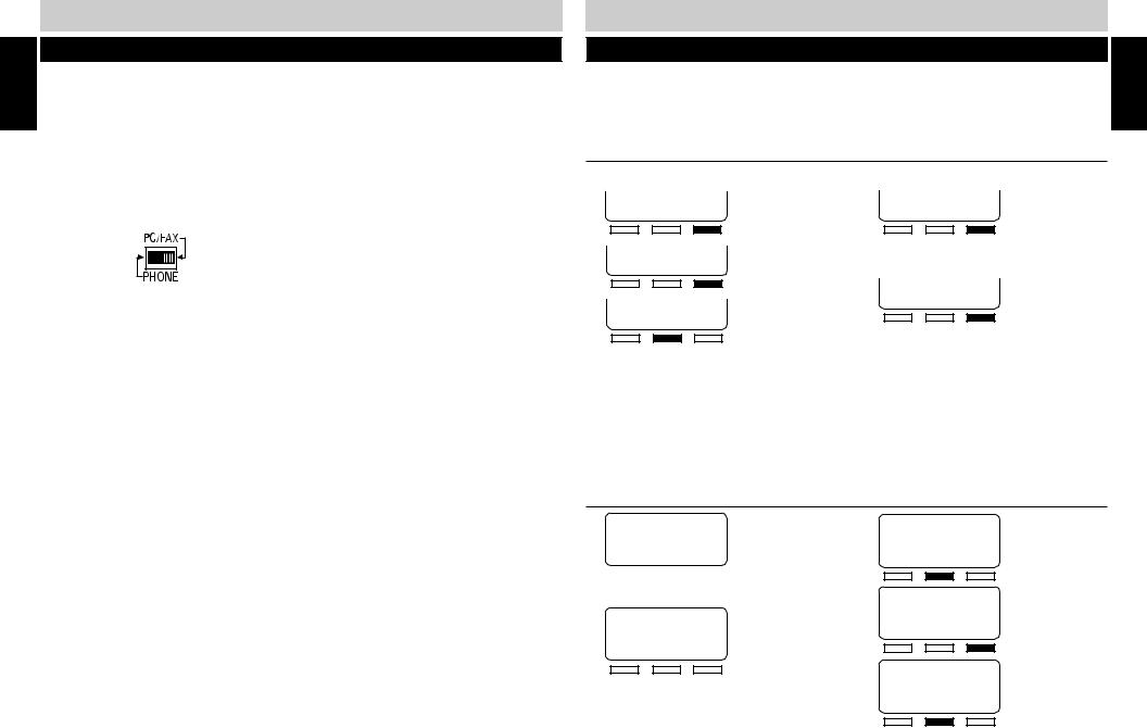
CONNECTING A FAX OR PC MODEM TO THE DATA PORT
You can connect a fax or PC modem to the SI-460 Data Port, located on the upper left rear side of the unit. This data port is connected to line 2. When a fax or PC modem is connected to the Data Port, and it is in use by the fax or PC modem, the connection is protected and cannot be interrupted by incoming or transferred calls.
The data port is ALWAYS active, regardless of the position of the PC/FAX switch. Placing the switch in the PC/FAX position silences the ring and turns off line status indication for that line and prevents the voice mail from answering incoming modem or fax calls.
1.Connect the line cord of the fax or PC modem into the Data Port, labeled “DOWN STREAM”.
2.Position the PC/FAX switch to the PC/FAX position.
If a fax is connected at a station that is sharing line 2, each station connected to the common line 2 should have the PC/FAX switch set to the “PC/FAX” postion. When a call is received on line 2, only the fax will ring and answer the call. If auto attendant in on, line 2 will not ring and auto attendant will not answer the call. When set to the PC/FAX setting, line two is a dedicated fax and modem line.
10
INITIAL SETUP
QUICK SETUP
On initial power-up (the line cord(s) and AC adapter are connected) each station will prompt the user to set the station ID, time and date. All other system defaults (see SYSTEM DEFAULTS on page 13) are in place and the station is immediately ready for use. Refer to your completed system configuration diagram, on page 8, for rapid installation.
ASSIGNING A STATION EXTENSION NUMBER
Each station must have a different extension number assigned.
1. INITIAL SETUP START
2. SET STATION ID NEXT
3. SET STATION 11 CHANGE SAVE
Press the soft key under “CHANGE” until the chosen extension number (11-22) appears in the display.
NOTE:
■If another station’s ID number is chosen, an error beep will be heard and “NOT AVAIL” will appear in the display. Press the soft key under “CHANGE” to select another extension number.
4.
5.
6.
SET STATION 12
CHANGE SAVE
Press the soft key under “SAVE” to save station selection.
STATION 12 SET
BACK NEXT
Press the soft key under “NEXT” to program the time.
SETTING THE TIME AND DATE
1. 1/01 12:00 AM
TIME (HH:MM)
BACK SAVE NEXT
Use the keypad to enter the hour (two digits) and minutes (two digits).
2. 1/01 8:24 AM
TIME (HH:MM)
BACK SAVE NEXT
Your entries will appear in the display as they are typed. If the time entry is incorrect, press the soft key under “BACK” to re-enter the time.
3. 1/01 8:24 AM
TIME (HH:MM)
BACK SAVE NEXT
4. 1/01 8:24 AM
TIME (HH:MM)
BACK SAVE NEXT
5. 1/01 8:24 PM
AM/PM
BACK CHANGE NEXT
Press the soft key under “CHANGE” to toggle between “AM” and “PM”.
CONTINUED NEXT PAGE
11
SETUP INITIAL

INITIAL SETUP |
|
INITIAL SETUP |
SETUP |
|
|
|
|
|
|
|
|
|
|
|
|
|
QUICK SETUP (cont.) |
|||||||||||||||
|
SETTING THE TIME AND DATE (cont.) |
|
|
|
|
|
|
|
|
|
|
|
|
|
|
|
|||||||||||||
INITIAL |
|
|
|
|
|
|
|
|
|
|
|
|
|
|
|
|
|||||||||||||
|
6 |
. |
|
|
|
|
|
|
|
|
|
|
|
10. |
|
|
|
|
|
|
|
|
|
|
|
|
|
|
|
1/01 |
|
8:24 PM |
|
|
|
DAY: SUNDAY |
|||||||||||||||||||||||
|
|
|
|
|
AM/PM |
|
|
|
BACK CHANGE NEXT |
||||||||||||||||||||
|
|
|
|
|
|
|
|
|
|||||||||||||||||||||
|
|
|
|
|
|
|
|
|
|
|
|
|
|
|
|
|
|
|
|
|
|||||||||
|
|
|
|
|
BACK CHANGE NEXT |
|
|
|
|
|
|
|
|
|
|
|
|
|
|
|
|||||||||
|
|
|
|
|
|
Press the soft key under “CHANGE” until |
|||||||||||||||||||||||
|
|
|
|
|
|
|
|
|
|
|
|
|
|
|
|
||||||||||||||
|
|
|
|
|
|
|
|
|
|
|
|
|
|
|
|
||||||||||||||
|
|
7. Use the keypad to enter the month (01-12) |
|
the correct week day appears in the |
|||||||||||||||||||||||||
|
|
|
|
and day (01-31). To edit your entry, press |
|
|
display. |
|
|
||||||||||||||||||||
|
|
|
|
11. |
|
|
|
|
|
|
|
|
|
|
|
|
|
|
|||||||||||
|
|
|
|
the soft key under “BACK” to re-enter the |
|
|
|
DAY: MONDAY |
|||||||||||||||||||||
|
|
|
|
date. |
|
|
|
|
|
|
|
|
|
BACK CHANGE NEXT |
|||||||||||||||
|
8 |
. |
4/ 18 |
|
8:24 PM |
|
|
|
|
|
|
|
|
|
|
|
|
|
|
|
|||||||||
|
|
12. “INITIAL SETUP COMPLETE” will |
|||||||||||||||||||||||||||
|
|
|
|
|
|
DATE |
|
(MM:DD) |
|||||||||||||||||||||
|
|
|
|
|
BACK |
|
|
SAVE NEXT |
|
appear in the display. |
|||||||||||||||||||
|
9. |
|
|
|
|
|
|
|
|
|
|
|
|
|
|
|
|
|
|
|
|
|
|
|
|
||||
|
|
|
|
|
|
|
|
|
|
|
|
|
|
|
|
|
|
|
|
|
|
|
|
|
|
|
|||
|
|
|
|
|
|
|
|
|
|
|
|
|
|
|
|
|
|
|
|
|
|
|
|
|
|
|
|||
|
|
|
DATE |
|
(MM:DD) |
|
|
|
|
|
|
|
|
|
|
|
|
|
|
|
|||||||||
|
|
|
|
|
BACK |
|
SAVE NEXT |
|
|
|
|
|
|
|
|
|
|
|
|
|
|
|
|||||||
|
|
|
|
|
|
|
|
|
|
|
|
|
|
|
|
|
|
|
|||||||||||
|
|
|
|
|
|
|
|
|
|
|
|
|
|
|
|
|
|
|
|
|
|
|
|
|
|
|
|
|
|
|
|
VERIFYING STATION AND LINE CONFIGURATION |
|||||||||||||||||||||||||||
|
1 |
. Press |
LINE 1 . The LINE 1 INDICATOR will light green and the speakerphone LED will |
||||||||||||||||||||||||||
|
|
|
|
light red. |
|
|
|
|
|
|
|
|
|
|
|
|
|
|
|
||||||||||
|
2 |
. The station ID will appear in the display to indicate the station is |
in use. |
1/01 12:57 AM 12 |
|||||||||||||||||||||||||
|
3 |
. Dial the telephone number for line 2 on a standard phone. The LINE |
INDICATOR for line 2 |
|
|||||||||||||||||||||||||
|
|
|
|
should flash red. If the line indicator, for the line you called, does not |
flash, check to make |
|
|||||||||||||||||||||||
|
|
|
|
sure lines are correctly installed. |
|
|
|
|
|
|
|
|
|
|
|
|
|
|
|
||||||||||
|
4 |
. Repeat step 2 and call the telephone numbers for line 3 and 4. |
|||||||||||||||||||||||||||
|
5 |
. If the indicators of the lines you called flashed, you have successfully installed this station! |
|||||||||||||||||||||||||||
|
|
VERIFYING SYSTEM CONFIGURATION |
|
|
|
|
|
|
|
|
|
|
|
|
|
|
|
||||||||||||
|
|
To verify that all stations are communicating, |
|
|
|
|
|
|
|
|
|
|
|
|
|
|
|
||||||||||||
|
1 |
. Press and hold PAGE ALL . |
|
|
|
|
|
|
|
|
|
|
|
|
|
|
|
||||||||||||
|
2 |
. “PAGING” and the station icons for all properly connected stations will appear in the Station |
|||||||||||||||||||||||||||
|
|
|
|
Status Display. It may take a moment for all the icons to appear. |
|||||||||||||||||||||||||
|
3 |
. Check to see if all stations connected to line 1, appear in the display. If they did, the system is |
|||||||||||||||||||||||||||
|
|
|
|
successfully configured. If all the stations do not appear in the display, note the station(s) that |
|||||||||||||||||||||||||
|
|
|
|
did not appear in the display. Go to the noted station and make sure the lines are connected |
|||||||||||||||||||||||||
|
|
|
|
and in the correct line jacks. |
|
|
|
|
|
|
|
|
|
|
|
|
|
|
|
||||||||||
|
|
|
|
|
|
|
|
|
12 |
|
|
|
|
|
|
|
|
|
|
|
|
|
|
|
|||||
QUICK SETUP (cont.)
INSTALLATION CHECKLIST
AC adapter is connected at stations
Line cords have been connected
Line 1 is common on all stations
All stations have been assigned an extension number
The time and date have been set at all stations
SYSTEM DEFAULTS
Once initial setup is complete, the SI-460 is ready to use with the following program defaults. Programming each of the settings below needs to be done at each station:
|
PROGRAM FEATURE |
FACTORY PRESET SETTING |
REFERENCE PAGE |
|
|
Always Ring |
Always Ring is OFF |
18 |
|
|
Answering System |
The answering system is OFF |
22 |
|
|
|
|
|
|
|
Answering System Ringer |
The answering system ringer is set to 4 rings |
25 |
|
|
|
|
|
|
|
Area Code |
The area code is set to “000” |
16 |
|
|
|
|
|
|
|
Auto Answer |
Auto Answer is ON for intercom use |
15 |
|
|
Auto Attendant |
Auto Attendant is OFF |
34 |
|
|
|
|
|
|
|
Caller ID |
Caller ID is set to ON and ANSWER, |
30 |
|
|
|
so all answered caller ID records are retained |
|
|
|
|
|
|
|
|
Call Screen |
Call Screen is set to OFF |
47 |
|
|
|
|
|
|
|
Call Waiting Caller ID |
Call Waiting Caller ID is ON |
30 |
|
|
|
|
|
|
|
Default Ringer Volume |
The default ringer volume is set to HIGH |
17 |
|
|
|
(on the back of the SI-460) |
|
|
|
|
|
|
|
|
Flash |
Flash is set to 600 MS |
17 |
|
|
Greeting Mode Select |
The greeting mode is set to ANSWER |
24 |
|
|
|
|
|
|
|
Greeting Select |
The greeting select mode is set to answer |
22 |
|
|
|
with greeting 1 |
|
|
|
|
|
|
|
|
Greeting Timer |
Greeting Timer is OFF |
23 |
|
|
|
|
|
|
|
Outside Line |
The outside line is set to “-“ |
16 |
|
|
|
|
|
|
|
Pre-Recorded Greeting |
When the user has not recorded a greeting, |
20 |
|
|
|
when they play the greeting they will hear |
|
|
|
|
“Please record a new greeting one.” |
|
|
|
|
|
|
|
|
Private Line |
Private Line is OFF on line 3 and 4 |
18 |
|
|
|
|
|
|
|
Remote Code |
The remote code is set to “1-2-3” |
31 |
|
|
|
|
|
|
|
Ringer |
The ringer is ON for all installed lines |
17 |
|
|
|
13 |
|
|
SETUP INITIAL

PROGRAMMING THE TELEPHONE
The SI-460 can be customized to meet your needs.
ASSIGNING A STATION EXTENSION NUMBER
Each station must have a different extension number assigned.
PROGRAMMING
1.
2.
3.
4.
Press PROGRAM .
PLEASE SELECT PHON ANSW OTHER
CALLER ID ON BACK CHANGE NEXT
SET STATION ID BACK ENTER NEXT
5. SET STATION 11 BACK CHANGE SAVE
Press “CHANGE” until the chosen extension number (11-22) appears in the display.
NOTE:
■If another station’s ID number is chosen, an error beep will be heard and “NOT AVAIL” will appear in the display. Press the soft key under “CHANGE to select another extension number.
6. SET STATION 11 BACK CHANGE SAVE
7. Press PROGRAM to exit.
SETTING THE TIME AND DATE
The LCD displays the time and day and a synthesized voice announces the time and day a message was received, prior to a message being playbacked.
1.
2.
3.
4.
5.
Press PROGRAM .
PLEASE SELECT
PHON ANSW OTHER
AUTO ATTND:OFF
BACK CHANGE NEXT
TIME&DAY SETUP
BACK ENTER NEXT
“TIME (HH:MM)” will appear in the display. Use the keypad to enter the hour (01-12) and minutes (00-59).
14
6. 1/01 12:57 AM
TIME (HH:MM)
BACK SAVE NEXT
Your entries will appear in the display as they are typed. If the time entry is incorrect, press the soft key under “BACK” to re-enter the time.
7. 1/01 12:57 AM
TIME (HH:MM)
BACK SAVE NEXT
The programmed time will then appear in the display.
CONTINUED NEXT PAGE
PROGRAMMING THE TELEPHONE
SETTING THE TIME AND DATE (cont.)
8. 1/01 12:57 AM
TIME (HH:MM)
BACK SAVE NEXT
9. Press the soft key under “CHANGE” to toggle between “AM” and “PM.”
10. 1/01 12:57 PM
AM/PM
BACK CHANGE NEXT
11. “DATE (MM/DD)” will appear in the display. Use the keypad to enter the month (01-12) and the day (01-31). To edit your entry, press the soft key under “BACK” to re-enter the date.
12. 4/ 16 12:57 PM
DATE (MM:DD)
BACK SAVE NEXT
13. DATE (MM:DD) BACK SAVE NEXT
14. DAY: SUNDAY BACK CHANGE NEXT
Press the soft key under “CHANGE” until the correct week day appears in the display.
15. DAY: MONDAY BACK CHANGE NEXT
16. Press PROGRAM to exit.
PROGRAMMING
SETTING AUTOMATIC ANSWER
When auto answer is turned on and a station receives an intercom call, the station does not intercom ring, instead, the speakerphone automatically answers the intercom call.
To program the auto answer feature,
1 |
. Press |
PROGRAM . |
6. Press the soft key under “CHANGE” to |
||||||||||||||
2 |
. |
|
|
|
|
|
|
|
|
toggle between “ON” and “OFF.” |
|||||||
|
PLEASE SELECT |
|
|||||||||||||||
|
|
|
|
|
|
|
|
|
|
||||||||
|
|
PHON |
ANSW OTHER |
|
|
|
|
|
|
|
|
|
|||||
|
|
|
|
|
|
|
|
|
|
|
AUTOANSWER: ON |
||||||
|
|
|
|
|
|
|
|
|
|
||||||||
3 |
. |
|
|
|
|
|
|
|
|
BACK CHANGE NEXT |
|||||||
|
FLASH: 600 MS |
||||||||||||||||
|
|
|
|
|
|
|
|
|
|
||||||||
|
|
|
|
|
|
|
|
|
|
||||||||
4 |
. |
BACK CHANGE NEXT |
7. Once your selection appears in the display, |
||||||||||||||
|
|
|
|
|
|
|
|||||||||||
|
|
|
|
|
|
|
|||||||||||
|
|
|
|
|
|
|
|||||||||||
|
|
|
|
press PROGRAM to exit. |
|||||||||||||
|
AUTODIAL SETUP |
||||||||||||||||
|
|
BACK |
ENTER NEXT |
|
|
|
|
|
|
|
|
|
|||||
5 |
. |
|
|
|
|
|
|
|
|
|
|
|
|
||||
|
|
|
|
|
|
|
|
|
|
|
|
|
|
|
|
||
|
|
|
|
|
|
|
|
|
|
|
|
||||||
|
RINGER SELECT |
|
|
|
|
|
|
|
|
|
|||||||
|
|
BACK |
ENTER NEXT |
|
|
|
|
|
|
|
|
|
|||||
|
|
|
|
|
|
|
|
|
15 |
|
|
|
|
|
|
|
|
|
|
|
|
|
|
|
|
|
|
|
|
|
|
|
|
|
|
|
|
|
|
|
|
|
|
|
|
|
|
|
|
|
|
|
|

PROGRAMMING
PROGRAMMING THE TELEPHONE
SETTING THE OUTSIDE LINE
If you must dial an outside line to access a dial tone, you can program the phone to automatically dial the outside digit when calling a stored caller ID record.
1.
2.
3.
4.
5.
Press PROGRAM .
PLEASE SELECT PHON ANSW OTHER
CALLER ID BACK ENTER NEXT
CWCID ON
BACK CHANGE NEXT
SAVE: ALL BACK CHANGE NEXT
6. OUTSIDE LINE:- BACK CHANGE NEXT
Press the soft key under “CHANGE” until the correct digit is displayed. (0 1 2 3 4 5 6 7 8 9 )
NOTE:
■If an outside line is not needed, make sure there is a “-” in the display.
7. When the correct outside line digit
appears in the display, press PROGRAM to exit.
SETTING THE AREA CODE
The area code is always included in caller ID records with telephone numbers. When your local area code is programmed into the SI-460 and you press DIAL to call a local caller ID record, the area code is automatically removed.
If your local telephone company only requires 7-digits to make local calls, you need to program your local area code. If your telephone company requires you to dial 10-digits for local calls, you do NOT need to program the area code into the SI-460. If you are uncertain of your local calling services, please contact your local telephone company.
To program your local area code,
1 |
. |
Press |
PROGRAM . |
5 |
. |
|
|
SAVE: ALL |
||||||||||||||||
|
|
|
|
|
|
|
|
|
|
|
|
BACK CHANGE NEXT |
||||||||||||
2 |
. |
|
|
|
|
|
|
|
|
|
|
|
|
|
|
|||||||||
|
PLEASE SELECT |
|
|
|
|
|
|
|
|
|
|
|
||||||||||||
|
|
PHON |
|
ANSW OTHER |
6 |
. |
|
|
|
|
|
|
|
|
|
|||||||||
|
|
|
|
|
|
|
|
|
|
|
||||||||||||||
|
|
|
|
|
|
|
|
|
|
|
|
|
|
|
|
|
|
|
|
|
|
|||
|
|
|
|
|
|
|
|
|
|
|
|
|
|
|
OUTSIDE LINE:- |
|||||||||
|
|
|
|
|
|
|
|
|
|
|
|
|
|
|||||||||||
|
|
|
|
|
|
|
|
|
|
|
|
|
|
|||||||||||
3 |
. |
|
|
|
|
|
|
|
|
|
|
|
|
|
|
BACK CHANGE NEXT |
||||||||
|
CALLER ID |
|
|
|
||||||||||||||||||||
|
|
|
|
|
|
|
|
|
|
|
|
|||||||||||||
|
|
BACK |
ENTER NEXT |
|
|
|
|
|
|
|
|
|
|
|
||||||||||
|
|
7 |
. Using the keypad, enter in your three digit |
|||||||||||||||||||||
|
|
|
|
|
|
|
|
|
|
|
|
|
||||||||||||
|
|
|
|
|
|
|
|
|
|
|
|
|
||||||||||||
|
|
|
|
|
|
|
|
|
|
|
|
|
||||||||||||
4 |
. |
|
|
|
|
|
|
|
|
|
|
|
|
|
area code. |
|
||||||||
|
CWCID ON |
8 |
. |
|
||||||||||||||||||||
|
|
|
|
|
|
|
||||||||||||||||||
|
|
BACK CHANGE NEXT |
|
|
|
|
|
|
|
|
||||||||||||||
|
|
AREA CODE: 310 |
||||||||||||||||||||||
|
|
|
|
|
|
|
|
|
|
|
|
|
|
|
|
BACK |
SAVE NEXT |
|||||||
|
|
|
|
|
|
|
|
|
|
|
|
|
|
|
|
|||||||||
|
|
|
|
|
|
|
|
|
|
|
|
|
|
|
|
|||||||||
|
|
|
|
|
|
|
|
|
|
|
|
|
|
|
|
|
|
|||||||
|
|
|
|
|
|
|
|
|
|
|
|
|
|
|
|
|
|
|
|
|
|
|
|
|
|
|
|
|
|
|
|
|
|
|
|
|
|
9 |
. Press |
PROGRAM to exit. |
|||||||||
|
|
|
|
|
|
|
|
|
|
|
|
|
16 |
|
|
|
|
|
|
|
|
|
|
|
PROGRAMMING THE TELEPHONE
SETTING THE RINGER ON/OFF BY LINE
Ringer settings for each outside line are individually controlled at each station. When the ringer is turned “ON,” the line will ring when calls are received. When the ringer is turned “OFF,” that line will not ring when a call is received. Whether the ringer is turned on or off, the LINE INDICATORS will operate normally.
You can determine which lines ring at your station. All four lines are factory preset to ring on the SI-460.
1. Press PROGRAM .
2. PLEASE SELECT PHON ANSW OTHER
3. FLASH: 600 MS BACK CHANGE NEXT
4. AUTODIAL SETUP BACK ENTER NEXT
5. RINGER SELECT BACK ENTER NEXT
The “LINE RING” and line number will appear on the display.
6. LINE1 RING:ON BACK CHANGE NEXT
Press the soft key under “CHANGE” to toggle between turning the ringer “ON” or “OFF” for the selected line.
7. LINE1 RING:OFF BACK CHANGE NEXT
Press the soft key under “NEXT” to advance to the next line selection.
8. Repeat steps 6 and 7 until all lines have been programmed.
9. Press PROGRAM to exit.
RINGER VOLUME
The ringer volume can be set to HI, LOW or OFF. The ringer volume is factory preset to HIGH. The ringer volume switch is located on the back of the SI-460. To adjust the ringer volume, move the ringer volume switch to the desired position. When the ringer volume is turned off, the unit will not ring when a call is received.
OFF LO HI RING VOL.
ADJUSTING FLASH DURATION
The flash setting is factory preset to 600 milliseconds, which is appropriate for most areas. The flash can be set to 100 MS – 1000MS. If you are in an environment where a different flash duration is needed:
1.
2.
Press PROGRAM .
PLEASE SELECT PHON ANSW OTHER
3. FLASH: 600 MS BACK CHANGE NEXT
Press the soft key under “CHANGE” until your selection flash duration appears.
4. Press PROGRAM to exit.
17
PROGRAMMING

PROGRAMMING
PROGRAMMING THE TELEPHONE
SETTING ALWAYS RING
The Always Ring default setting is OFF. There are a few situations when a station will not ring.
1.A station will not ring when the auto attendant is on, unless the incoming call is transferred to your station.
2.Your unit will ring when the auto attendant is off, but if you are already on the line, your station will not ring when someone is calling in on another line.
If you would like your station to ring when off-hook on another line or when a call comes into the auto attendant, set Always Ring to ON.
1 |
. Press |
PROGRAM . |
5. |
RINGER SELECT |
|
2 |
. |
PLEASE SELECT |
|
BACK ENTER NEXT |
|
|
|
||||
|
|
PHON |
ANSW OTHER |
6. |
|
|
|
|
|
AUTOANSWER: OFF |
|
3 |
. |
FLASH: 600 MS |
|
BACK CHANGE NEXT |
|
|
|
||||
|
|
BACK CHANGE NEXT |
7. ALWAYSRING: OFF |
||
|
|
|
|
||
4 |
. |
AUTODIAL SETUP |
|
BACK CHANGE NEXT |
|
|
|
||||
|
|
BACK |
ENTER NEXT |
8. Press PROGRAM to exit. |
|
|
|
|
|
||
SETTING A PRIVATE LINE
You must share lines 1 and 2 with all other stations in the system. However you can create a non-square configuration as described on page 7 using lines 3 and/or 4 so that your station has different telephone numbers from the other stations’ lines 3 and/or 4. More than one station can share a private line. Once the private lines are connected to your unit, follow the programming
steps below: |
7. ALWAYSRING: OFF |
Press PROGRAM . |
BACK CHANGE NEXT |
PLEASE SELECT PHON ANSW OTHER
FLASH: 600 MS BACK CHANGE NEXT
AUTODIAL SETUP BACK ENTER NEXT
RINGER SELECT BACK ENTER NEXT
AUTOANSWER: OFF BACK CHANGE NEXT
8. PRIV LINE: OFF BACK CHANGE NEXT
9. OFF
BACK SAVEON/OFF
10. Use the keypad to select the line(s) that you want to be private. Your private line selection will appear in the display.
11. ON:SELECT LN34 BACK SAVEON/OFF
12. Press PROGRAM to exit.
NOTE:
■Two or more stations can share the same private line(s), but under this condition your private line calls will always be accessible (privacy is always released) to other stations that share the same line.
PROGRAMMING THE VOLUME
You can individually set the volume level for the handset, speaker and headset and when using or switching applications, the set volume level is automatically adjusted.
HANDSET VOLUME
While using the handset: |
|
||
1 |
. Press |
to adjust the handset volume. |
PROGRAMMING |
|
setting will remain at this level until it is changed or a power failure occurs. |
||
|
|
VOLUME |
|
2 |
. As the volume is adjusted, 1-5 bars will appear on the LCD to visually display the handset |
|
|
|
volume level. (1 bar representing low and 5 bars representing high volume.) The volume |
|
|
4/25 3:52 PM 15
VOLUME
SPEAKERPHONE / INTERCOM VOLUME
When using the speakerphone/intercom or when the phone is in standby mode,
1. Press |
to set the speakerphone volume to the desired level. |
|
VOLUME |
2. As the volume is adjusted, 1-8 sets of bars will appear to visually display the volume level on the LCD. The volume setting will remain at this level until it is changed or a power failure occurs. The lowest speakerphone volume is off.
When set to off, the display will show:
|
HEADSET VOLUME |
While using the headset: |
|
1. Press |
to adjust the headset volume. |
|
VOLUME |
2. As the volume is adjusted, 1-5 bars on the LCD will appear to visually display the headset volume level. (1 bar representing low and 5 bars representing high volume.) The volume setting will remain at this level until it is changed or a power failure occurs.
18 |
19 |
PROGRAMMING
PROGRAMMING THE ANSWERING SYSTEM
Each SI-460 in the system has its own built-in answering system capable of playing up to six greetings. The total recording time for each SI-460 is 28 minutes. To program the auto attendant station, see page 32.
Each of the SI-460’s six greetings have the following default greeting, “Please record a message after the tone” and should be personalized to direct callers to access any station’s additional greetings by entering the corresponding numbers as follows:
Greeting 1 - Caller dials: 01 |
Greeting 4 - Caller dials: 04 |
Greeting 2 - Caller dials: 02 |
Greeting 5 - Caller dials: 05 |
Greeting 3 - Caller dials: 03 |
Greeting 6 - Caller dials: 06 |
Bypass greetings to record a message - Caller presses: #
Greetings can be set up to 1) greet the caller, 2) provide specific information to callers, 3) allow the caller to record a message, 4) route a call or 5) announce a message only and not enable the caller to leave a message.
An example, of a station greeting would be:
“Hello, you have reached the desk of Jane Dee, Financial Consultant. If you would like to leave a message, begin speaking after the tone. To hear today’s top ten mutual funds, press 02 now. To hear a listing of today’s top stock bargains, press 03 now. To listen to today’s interest rate, please press 04. To hear what the NASDAQ, Dow Jones 30 and Standard and Poor Indexes last closed at, press 05 now. To hear this week’s stock news highlights, press 06 now. If you would like this greeting to repeat, press 01 now.”
Greetings 2, 3 and so on should be recorded accordingly.
You can also select different greetings to play during specified times. See page 23 under “SETTING THE GREETING TIMER ON.”
RECORDING GREETINGS
Record the primary greeting and then all the additional greetings for a station. You should script your station greeting to save time and ensure all pertinent information is included.
When all necessary greetings have been recorded you need to:
1.Select which greeting will answer all incoming calls and
2.Select whether callers will be able to leave messages on the unit (ANSWER), or if all callers will be able to only hear messages and not leave messages (ANNOUNCE ONLY).
20
1.
2.
3.
4.
5.
Press PROGRAM .
PLEASE SELECT
PHON ANSW OTHER
AUTO ATTND:OFF
BACK CHANGE NEXT
TIME&DAY SETUP
BACK ENTER NEXT
GREETING SETUP
BACK ENTER NEXT
CONTINUED NEXT PAGE
PROGRAMMING THE ANSWERING SYSTEM
|
|
|
|
|
|
RECORDING GREETINGS (cont.) |
|||||||||
6. |
|
|
|
|
|
|
9. |
|
|
||||||
|
RECORD GRT |
|
RECORDING 1 |
||||||||||||
|
BACK ENTER NEXT |
|
|
|
|
STOP |
|||||||||
|
|
|
|
|
|
|
|
|
|
|
|
|
|
|
|
|
|
|
|
|
|
|
|
|
|
|
|
|
|
|
|
7. |
|
|
|
|
|
|
Press the soft key under “STOP” when you |
||||||||
|
RECORD GRT 1 |
|
|||||||||||||
|
|
have finished recording. The greeting will |
|||||||||||||
|
BACK ENTER NEXT |
|
|||||||||||||
automatically playback.
Press the soft key under “NEXT” to scroll to the greeting you want to record.
8. Press the soft key under “ENTER“ when you are ready to begin recording your greeting. “RECORDING 1” will appear in the display and you will hear, “Please record a new greeting one” followed by a beep. After the beep, begin speaking clearly, about eight inches from the microphone.
10. RECORD GRT1 BACK ENTER NEXT
Press the soft key under “NEXT” until the next greeting you want to record appears in the display.
11. Repeat steps 7-10 to continue recording the remaining greetings.
12. Press PROGRAM to exit.
CHECKING THE GREETING
You can listen to your recorded greetings at anytime. If a greeting has not been recorded, you
will hear “Please record a new greeting.”
To review recorded greetings,
1. Press PROGRAM .
2. PLEASE SELECT PHON ANSW OTHER
3. AUTO ATTND:OFF BACK CHANGE NEXT
4. TIME&DAY SETUP BACK ENTER NEXT
5. GREETING SETUP BACK ENTER NEXT
6. RECORD GRT BACK ENTER NEXT
7. SELECT GRT BACK ENTER NEXT
8. GRT MODESELECT BACK ENTER NEXT
9. CHECK GREETING BACK ENTER NEXT
10. PLAY GREETING1 BACK START NEXT
Press the soft key under “NEXT” until the selected greeting appears in the display.
11. PLAY GREETING2 BACK START NEXT
12. Press PROGRAM to exit programming.
21
PROGRAMMING

PROGRAMMING
PROGRAMMING THE ANSWERING SYSTEM
SELECTING THE PRIMARY GREETING
The SI-460 can play up to six greetings. Once the primary greeting and all additional greetings have been recorded, the primary greeting should be set to answer calls.
NOTE:
■When greeting timer is programmed to play, you cannot select a primary greeting. The greeting that plays during the programmed time is always greeting 1. Greeting 2 plays the remainder of the time.
1.
2.
3.
4.
5.
6.
Press PROGRAM .
PLEASE SELECT PHON ANSW OTHER
AUTO ATTND:OFF BACK CHANGE NEXT
TIME&DAY SETUP BACK ENTER NEXT
GREETING SETUP BACK ENTER NEXT
RECORD GRT
BACK ENTER NEXT
7. SELECT GRT BACK ENTER NEXT
NOTE:
■If greeting timer is turned on, “CANNOT SELECT GREETING - GREETING TIMER IS ON” will scroll across the display.
8. GRT1 RECORDED BACK DONE CHANGE
Press the soft key under “CHANGE” to select the main greeting you want to answer calls.
9. Once your greeting selection appears in the display:
GRT2 RECORDED
BACK DONE CHANGE
10. Press PROGRAM to exit.
TURNING THE ANSWERING SYSTEM ON / OFF
The Executive Series is a business system and may operate differently than your home answering machine. Calls will not automatically be answered when a station has Voice Mail on. In order for calls to be automatically answered, Auto Attendant must be turned on in the system. The Auto Attendant will only answer the lines it is programmed to answer.
Voice Mail must be ON at a station in order to record messages. When a stations’ Voice Mail is OFF and calls are directed to that station, the station will ring without messages being taken. When the answering system is turned ON, the VOICEMAIL INDICATOR will light and the following display will appear on the LCD to indicate the number of new messages received and the total of all messages received.
To turn a station’s answering system on or off:
1. Press VOICEMAIL . ON/OFF
The VOICEMAIL INDICATOR will light to indicate voice mail is turned on.
22
2. Press VOICEMAIL again.
ON/OFF
The VOICEMAIL INDICATOR will not light to indicate voice mail is not turned on.
PROGRAMMING THE ANSWERING SYSTEM
SETTING THE GREETING TIMER ON
The SI-460 can be set to play greeting 1 at a pre-programmed time. The remainder of the time, greeting 2 will play as your primary greeting.
1. Press PROGRAM .
2. PLEASE SELECT PHON ANSW OTHER
3. AUTO ATTND:OFF BACK CHANGE NEXT
4. TIME&DAY SETUP BACK ENTER NEXT
5. GREETING SETUP BACK ENTER NEXT
6. RECORD GRT BACK ENTER NEXT
7. SELECT GRT BACK ENTER NEXT
8. GRT MODESELECT BACK ENTER NEXT
9. CHECK GREETING BACK ENTER NEXT
10. GRT TIMER OFF BACK CHANGE NEXT
11. OFF
BACK SAVE ON
12. 08:00 TO 05:00 BACK SET OFF
13. Use the keypad to enter the time |
||||||||
|
(4 digits) you want to initiate the |
|||||||
|
greeting timer. |
|||||||
14. |
|
|
|
|||||
|
FROM (09:30) |
|||||||
|
BACK |
|
|
|
NEXT |
|||
15. |
|
|
|
|
||||
|
|
|
|
|
|
|
|
|
|
|
|
|
|
|
|
|
|
|
FROM AM |
|||||||
|
BACK CHANGE NEXT |
|||||||
|
|
|
|
|||||
|
|
|
|
|
|
|
|
|
|
Press the soft key under “CHANGE” to |
|||||||
16. |
toggle between “AM” and “PM.” |
|||||||
|
FROM AM |
|||||||
|
BACK CHANGE NEXT |
|||||||
|
|
|
|
|
|
|||
|
|
|
|
|
|
|
|
|
17. Use the keypad to enter the time (4 |
||||||||
|
digits) you want to end the greeting |
|||||||
18. |
timer. |
|
|
|
|
|
|
|
|
TO (06:30) |
|
||||||
|
BACK |
|
|
|
NEXT |
|||
19. |
|
|
|
|
||||
|
|
|
|
|
|
|
|
|
|
|
|
|
|
|
|
|
|
|
|
|
|
|
||||
|
TO |
|
PM |
|||||
|
BACK CHANGE NEXT |
|||||||
|
|
|||||||
|
|
|
|
|
|
|
|
|
|
Press the soft key under “CHANGE” to |
|||||||
20. |
toggle between “AM” and “PM.” |
|||||||
|
TO |
|
PM |
|||||
BACK CHANGE NEXT
21. GRT2 FOR REST BACK YES NO
22. Press PROGRAM to exit.
23
PROGRAMMING
 Loading...