

Page 1
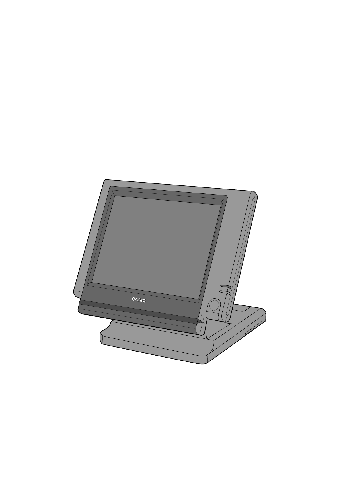
QT-6100
Touch Screen Smart Terminal
———————————————————————
Reference Manual
Version 1.0 June 2008
c
Page 2

Preface
This manual is intended to be used as a reference to the QT-6100 system. It provides details
to allow whole understanding of the system capabilities, its operation, and how it can be used
to solve many problems within the retail outlet. This manual does not describe actual
programming, which is covered in the QT-6100 programming manual.
This manual consists of the following chapters:
1. Introduction
This chapter describes the concepts of development of the QT-6100 system.
2. Hardware configuration
This chapter outlines the hardware, optional devices and configurations of QT-6100
system.
3. Application systems
This chapter outlines the application system and overviews the function provided for the
QT-6100 system.
4. Manager operation
This chapter explains the manager operations to use QT-6100 system.
5. Registrations
This chapter explains actual registration operations with example.
6. Refund mode operation
This chapter explains registrations in the RF or REG– mode.
7. Read and reset
This chapter explains detail of the read and reset operations and reports.
8. Appendices
These chapters show the record format and descriptions of individual files, total
calculation method, meaning of error messages, etc.
• System down and recovery (in the Installation and Down Recovery manual)
This chapter explains actions to take and recovery methods when the system goes down.
Note: Casio reserves the right to change equipment and specifications without obligation
and notification. The terms used in this manual may be different from those used in
other manuals of Casio’s product.
Printing history
Manual version Software version
Version 1.0: June, 2008 First Edition: June, 2008 Version 1.0
R-2
Page 3

Introduction
The QT-6100 is a versatile intelligent terminal developed in accordance with the following concepts.
1) System concept
Developing a high performance economical system by adopting the restaurant, bar, fast
food system.
– Shared check tracking
The QT-6100 system has the capability of check tracking system.
– Shared printer system
All terminals can share remote printer(s).
–Collection, consolidation, and auto-program functions
The QT-6100 system is equipped with these functions by utilizing high-speed in-line data
transfer system.
–Versatile terminal
With the QT-6100 system, any terminal has the same function, and can be designated as
the master terminal by programming.
2) Software concept
A flexible application system for development, adopting the following methods:
– Function classified application system
3) Terminal hardware concept
Color LCD with touch panel
In addition to the above, the QT-6100 is also a terminal following characteristics:
– Expandability
The QT-6100 system can be connected to various peripheral devices (slip printer, modem,
a personal computer, etc.)
– Reliability
The QT-6100 is provided with a self-diagnosis program so that the terminal can check the
hardware. When a malfunction occurs during processing, an error report is logged into the
system memory so that the error can quickly be corrected.
QT-6100 Reference Manual
R-3
Page 4

Contents
To prevent malfunctions caused by the weak batteries, charge the memory
protection batteries for over 12-hours before installation or after a longtime vacation
(over 30 days).
• Before installation, initialize the terminal and leave it turn on over 12-hours.
• After a longtime vacation, initialize the terminal and restore the program data if the
terminal is in malfunction, and leave it turn on over 12-hours.
• Over 48-hours charging makes the batteries fully charged.
R-4
Page 5

1. Hardware configuration ..................................................................... R-10
1-1. General configuration ............................................................................................ R-10
1-2. Hardware diagram ................................................................................................. R-11
1-3. Keyboard ............................................................................................................... R-12
1-4. Display................................................................................................................... R-13
1-5. Cash drawer .......................................................................................................... R-14
1-6. Input/output connectors......................................................................................... R-15
1-7. Optional peripherals .............................................................................................. R-16
1-8. System configuration............................................................................................. R-17
2. Application systems........................................................................... R-23
2-1. General description of application system ...................................... R-23
2-1-1. File concept ........................................................................................................... R-23
2-1-2. Linkage of totalizers .............................................................................................. R-24
2-1-3. Function keys ........................................................................................................ R-25
2-1-4. Keyboard layout..................................................................................................... R-25
2-1-5. Mode control ......................................................................................................... R-26
2-1-6. Operation prompt and error messages ................................................................. R-26
2-1-7. Printing control system .......................................................................................... R-26
2-2. General description of individual function keys ............................. R-29
2-2-1. System keys .......................................................................................................... R-29
2-2-2. Finalize keys.......................................................................................................... R-30
2-2-3. Transaction keys.................................................................................................... R-30
2-3. Remote printer control ....................................................................... R-38
2-3-1. Remote printer system configuration .................................................................... R-38
2-3-2. Remote printer control setting ............................................................................... R-39
2-3-3. Remote printer output control................................................................................ R-40
2-3-4. Remote printer backup processes ........................................................................ R-40
2-4. Check tracking system....................................................................... R-43
2-4-1. Shared check tracking system .............................................................................. R-43
2-4-2. Shared check tracking requirement....................................................................... R-44
2-4-3. Data backup when the master goes down ............................................................ R-44
2-5. Other check tracking system control ............................................... R-45
2-5-1. The timing to clear check detail and index file after finalization ............................ R-45
2-5-2. Table transfer ......................................................................................................... R-45
2-5-3. Store and recall ..................................................................................................... R-45
2-6. Clerk control function ........................................................................ R-47
2-6-1. Clerk interrupt ....................................................................................................... R-47
2-6-2. Clerk detail memory .............................................................................................. R-48
2-6-3. Clerk training ......................................................................................................... R-48
2-6-4. Manager mode control .......................................................................................... R-48
QT-6100 Reference Manual
R-5
Page 6

Contents
2-7. Arrangement key function and scheduler........................................ R-50
2-7-1. Arrangement key function ..................................................................................... R-50
2-7-2. Arrangement program example............................................................................. R-54
2-7-3. Scheduled execution of arrangement key function................................................ R-54
2-8. Making graphic logo........................................................................... R-55
2-8-1. About graphic logo ................................................................................................ R-55
2-8-2. Making graphic logo procedure ............................................................................. R-55
2-9. Hourly item .......................................................................................... R-56
2-9-1. Programming necessary files before using hourly item function. .......................... R-56
2-10. Time and attendance .......................................................................... R-57
2-10-1. Corresponding relations of the file ........................................................................ R-58
2-10-2. Clock-in operation ................................................................................................. R-60
2-10-3. Clock-out operation ............................................................................................... R-63
2-11. Sign on control ................................................................................... R-65
2-11-1. Sign on .................................................................................................................. R-65
2-11-2. Solution to abnormality of master terminal ............................................................ R-66
2-11-3. Solution to abnormality of satellite terminal .......................................................... R-66
2-11-4. Sign on compulsory .............................................................................................. R-66
2-12. IDC (Item Data Capture) ..................................................................... R-67
2-12-1. Available capturing items ...................................................................................... R-67
2-12-2. Set up the IDC start / end ..................................................................................... R-70
2-12-3. How to memorize the captured items .................................................................... R-71
2-12-4. IDC data file structure ........................................................................................... R-72
2-12-5. IDC data type ........................................................................................................ R-76
2-12-6. Transferring IDC .................................................................................................... R-77
2-13. Electronic journal ............................................................................... R-78
2-13-1. Storing electronic journal ...................................................................................... R-78
2-13-2. Issuing electronic journal report ............................................................................ R-78
2-13-3. Displaying electronic journal and producing guest receipts after sales ................. R-78
2-13-4. Transferring electronic journal memory ................................................................. R-79
3. Manager operation ............................................................................. R-82
3-1. Machine initialization ......................................................................... R-82
3-1-1. INIT ....................................................................................................................... R-82
3-1-2. Flag clear .............................................................................................................. R-82
3-1-3. INIT 2 .................................................................................................................... R-83
3-1-4. INIT code............................................................................................................... R-83
3-2. IPL (Initial Program Loading) ............................................................ R-83
3-2-1. IPL ......................................................................................................................... R-83
3-2-2. System configuration before IPL operation ........................................................... R-84
3-2-3. IPL operation ......................................................................................................... R-85
R-6
Page 7

3-3. Manager function................................................................................ R-86
3-3-1. System connection check ..................................................................................... R-86
3-3-2. Remote on............................................................................................................. R-87
3-3-3. Remote off............................................................................................................. R-87
3-3-4. Busy reset ............................................................................................................. R-88
3-3-5. Stock maintenance ................................................................................................ R-89
3-3-6. Drawer for clerk ..................................................................................................... R-90
3-3-7. CHK# (Clerk interrupt)........................................................................................... R-90
3-3-8. Order ID change.................................................................................................... R-91
3-3-9. Error log print ........................................................................................................ R-92
3-3-10. System re-configuration ........................................................................................ R-93
3-3-11. Item Data Capture ................................................................................................. R-94
3-3-12. Euro change over .................................................................................................. R-95
3-3-13. Clerk window ......................................................................................................... R-96
3-3-14. Customer ............................................................................................................... R-97
3-3-15. Customer busy reset ............................................................................................. R-98
3-3-16. Sound .................................................................................................................... R-98
3-3-17. Clerk number ......................................................................................................... R-99
3-3-18. Operation monitor ................................................................................................. R-99
3-3-19. FTP client ........................................................................................................... R-99-1
3-4. System command execution ........................................................... R-100
3-4-1. X/Z reporting ....................................................................................................... R-100
3-4-2. X/Z collection / consolidation............................................................................... R-101
3-4-3. Remote power control ......................................................................................... R-102
3-5. Data Communication System .......................................................... R-103
3-5-1. Inline / online connectors .................................................................................... R-103
3-5-2. Hardware interface .............................................................................................. R-104
3-5-3. Inline / online functions........................................................................................ R-106
3-6. Collection/Consolidation system .................................................... R-107
3-6-1. X/Z collection....................................................................................................... R-109
3-6-2. X/Z consolidation................................................................................................. R-111
3-6-3. X/Z collection / consolidation............................................................................... R-113
3-7. Auto-programming function ............................................................ R-116
3-7-1. Auto-programming functions ................................................................................ R-116
3-7-2. Auto-program operation and CF card utilities ...................................................... R-117
4. Registrations..................................................................................... R-122
4-1. Clerk sign on / off operation ................................................................................ R-122
4-2. Voiding the last registered item (<VOID> key operation) .................................... R-123
4-3. Voiding the previous registered item (<VOID> key operation)............................. R-124
4-4. Cancelling of all data registered during the transaction ...................................... R-124
4-5. Using the list function .......................................................................................... R-126
4-6. Using the set menu function and pulldown group function .................................. R-127
4-7. Post entry ............................................................................................................ R-130
4-8. Separate check ................................................................................................... R-131
QT-6100 Reference Manual
R-7
Page 8

Contents
4-9. Open check ......................................................................................................... R-132
4-10. Split payment (Dutch account) ............................................................................ R-132
4-11. Media change...................................................................................................... R-133
4-12. Eat-in / Takeout ................................................................................................... R-134
4-13. Scanning PLU ..................................................................................................... R-134
4-14. Shift PLU ............................................................................................................. R-135
4-15. Printing barcode on receipts (UP-360) ................................................................ R-135
4-16. Round repeat function ......................................................................................... R-136
4-17. (future use)
4-18. Customer............................................................................................................. R-138
4-19. Table sharing ....................................................................................................... R-139
4-20. Order character change ...................................................................................... R-139
5. Refund mode operation ................................................................... R-142
5-1. Selecting REF or REG– mode ............................................................................ R-142
6. Read and reset operations .............................................................. R-144
6-1. The procedures of reading or resetting ............................................................... R-144
6-2. Report sample ..................................................................................................... R-146
Appendix-1 Function key list ...................................................................... R-160
Appendix-2. File format ............................................................................... R-164
Appendix-3 Counter and Totalizer calculation method ............................ R-194
Index ...............................................................................................................R-206
R-8
Page 9

1. Hardware configuration ......................................................................... R-10
1-1. General configuration.................................................................................... R-10
1-2. Hardware diagram ........................................................................................ R-11
1-3. Keyboard ....................................................................................................... R-12
1-4. Display .......................................................................................................... R-13
1-5. Cash drawer .................................................................................................. R-14
1-6. Input/output connectors ................................................................................ R-15
1-7. Optional peripherals ...................................................................................... R-16
1-8. System configuration .................................................................................... R-17
QT-6100 Reference Manual
R-9
Page 10
Hardware Configuration
1. Hardware configuration
This section outlines the hardware, optional devices, and configurations of the QT-6100
system.
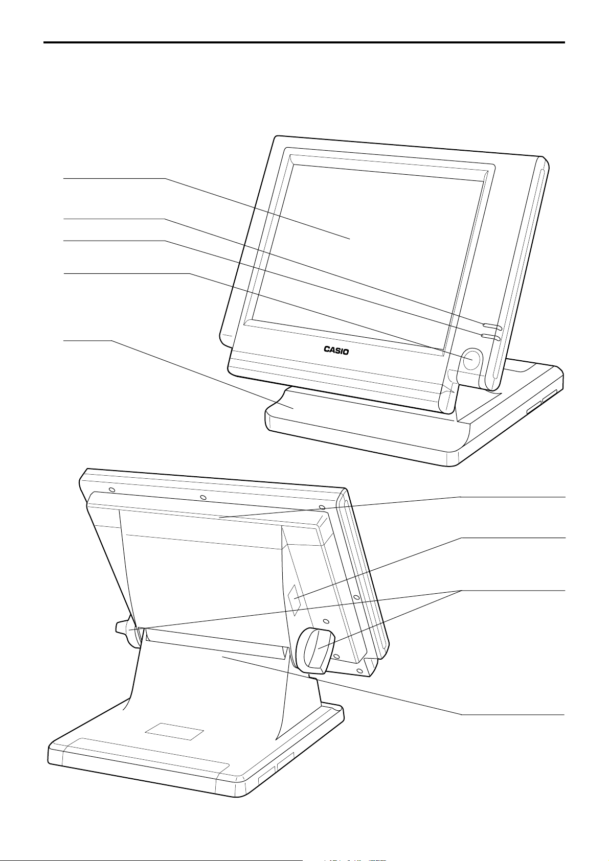
1-1. General configuration
Front view
Touch screen panel
Display on/off key
Pilot lamp
i-Button key receiver
(only for QT-6100-DLS)
Stand
Card slot cover
Power switch cover
Panel fixing screw
R-10
Connector cover
Rear view
Page 11
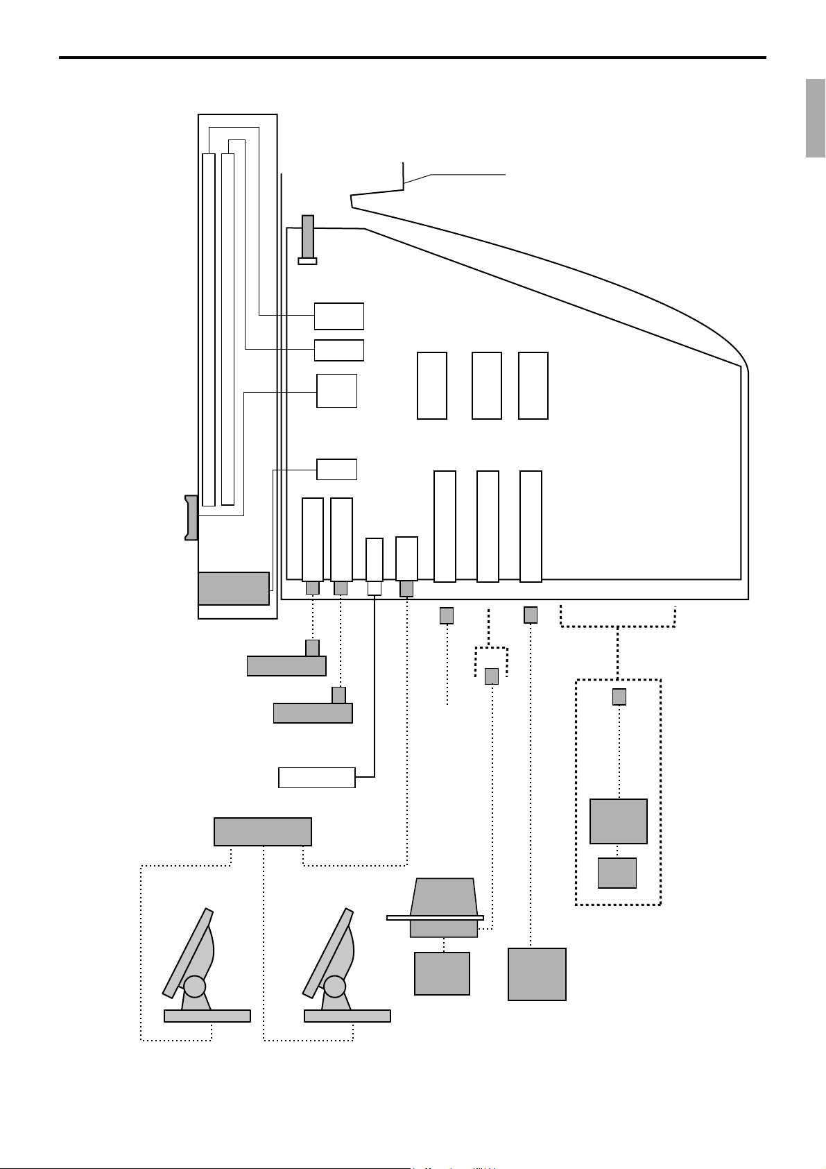
1-2. Hardware diagram
800 x 600 dot color LCD
Max. 95 key touch screen
CF card
i-Button
key i/f
Card slot cover
CPU
RAMFlash
Memory
16MB 32MB
QT-6011DLS
(except for
QT-6100-DLS)
Other terminals
or PC
MCR
QT-6046MCR
Drawer
HUB
Drawer 1 i/f
Drawer
AC Adptor
Drawer 2 i/f
CAT5 UTP cable
Inline
RS-232C COM1
PRL-CB-2
MODEM
or
PC
Slip
printer
SP-1300
Power
supply
AD31U/E
RS-232C COM2
RS-232C COM3
COM1/COM2/COM3
PRT-CB-8C
QT-6061CB or QT-6062CB
Remote
display
QT-6060D
PRT-CB-8A/-8B
Remote
printer
UP-360
Power
supply
Note: Shadowed device and dot line indicate option devices.
QT-6100 Reference Manual
R-11
Page 12
Hardware Configuration
1-3. Keyboard
1-3-1. Standard keyboard
REG C01 31-10-04 12:34 PM 001234
1234567890123456789012345678901234567890
1234567890123456789012345678901234567890
1234567890123456789012345678901234567890
1234567890123456789012345678901234567890
1234567890123456789012345678901234567890
1234567890123456789012345678901234567890
1234567890123456789012345678901234567890
1234567890123456789012345678901234567890
1234567890123456789012345678901234567890
1234567890123456789012345678901234567890
1234567890123456789012345678901234567890
•0.00
12345678901234567890
ESC/
SKIP
CLK4
CLK3
CLK2
CLK1
C X VOID
789
456
123
000•
• The keyboard layout is different by IPL.
YES NO
FUNC
LIST
COVERS
SEP
CHK
FIN.
LIST
RECEIPT
MODE CLK#
#/NS
SUBTOTAL NB
CASH/AMT
/TEND
PAGE
PLU010 PLU020 PLU030 PLU040 PLU050
UP
PLU009 PLU019 PLU029 PLU039 PLU049
PLU008 PLU018 PLU028 PLU038 PLU048
HOME
PLU007 PLU017 PLU027 PLU037 PLU047
PAGE
PLU006 PLU016 PLU026 PLU036 PLU046
DOWN
PLU005 PLU015 PLU025 PLU035 PLU045
PLU004 PLU014 PLU024 PLU034 PLU044
MENU
TBL
PLU003 PLU013 PLU023 PLU033 PLU043
TRANS
PLU002 PLU012 PLU022 PLU032 PLU042
NEW/OLD
PLU001 PLU011 PLU021 PLU031 PLU041
CHK
1-3-2. Hard key code of keyboard
005 010 015 020 025 030 035
(C)
004 009 014 019 024 029 034
(7) (8) (9)
003 008 013 018 023 028 033
(4) (5) (6)
002 007 012 017 022 027 032
(1) (2) (3)
001 006 011 016 021 026 031
(0) (00) (•)
045 055 065 075 085 095
044 054 064 074 084 094
043 053 063 073 083 093
042 052 062 072 082 092
041 051 061 071 081 091
040 050 060 070 080 090
039 049 059 069 079 089
038 048 058 068 078 088
037 047 057 067 077 087
036 046 056 066 076 086
R-12
• In case of assigning a double or quadruple key, the key code of the key is shadowed part
of the key.
Page 13
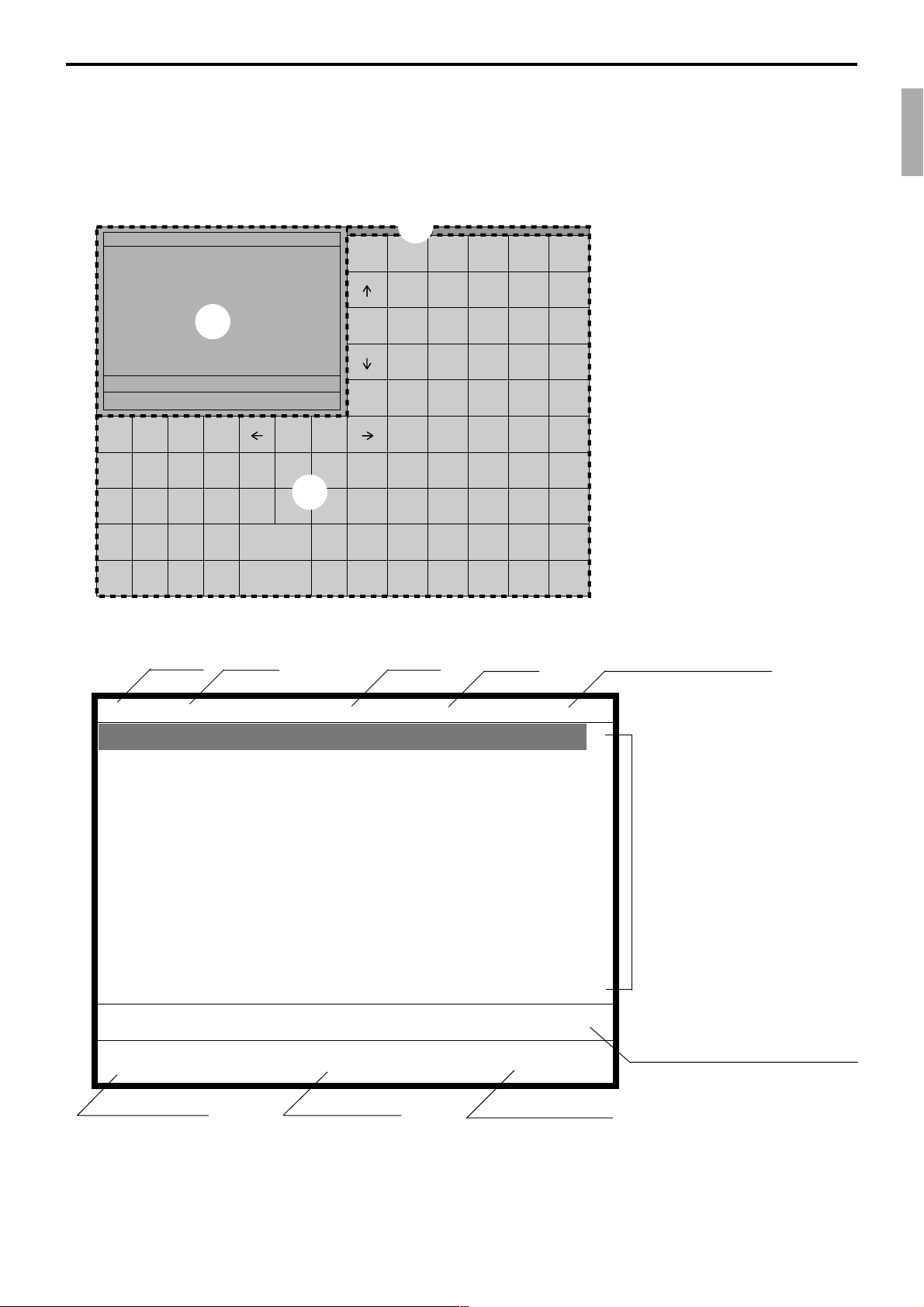
1-4. Display
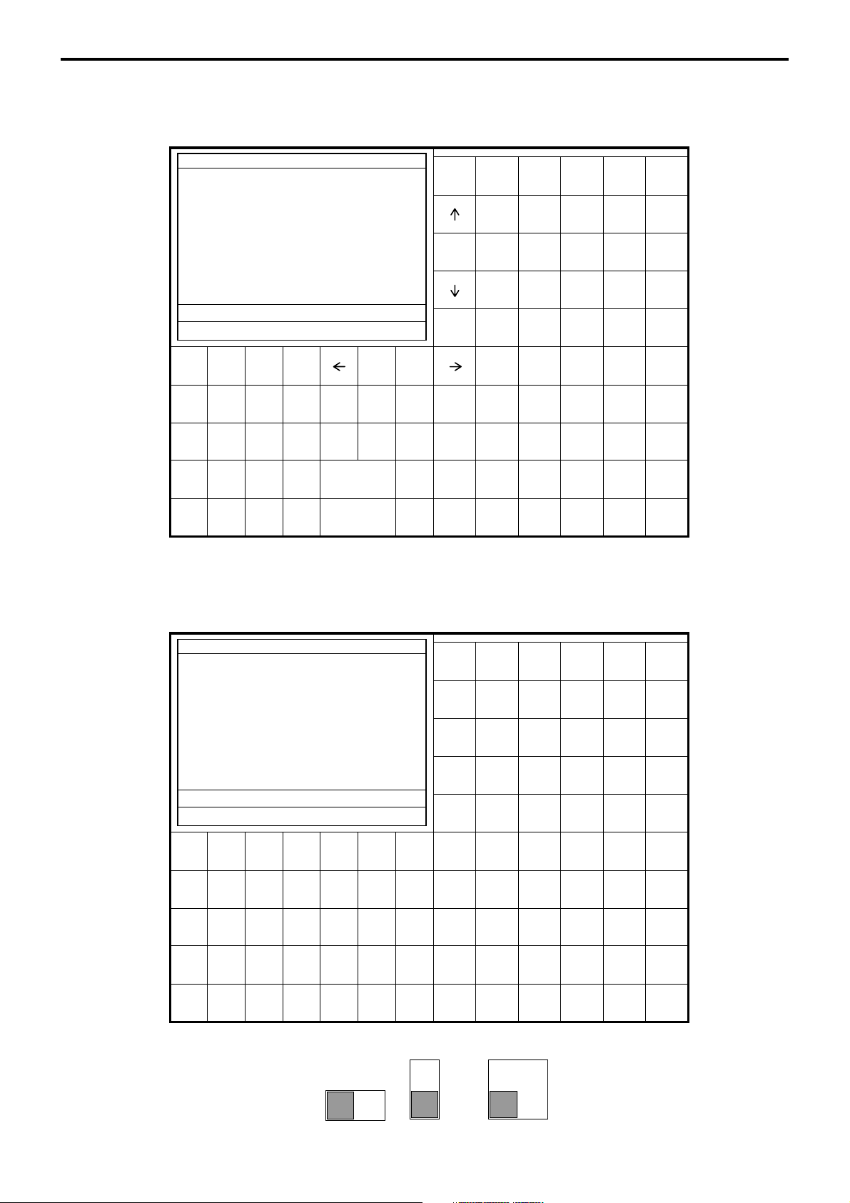
1-4-1. Main display part
1 Main display part: Used for displaying numeric entries, registration, subtotal amount, etc.
2
Menu level display part: Used for displaying the current shift PLU, menu sheet and 2nd unit price level.
3 Keyboard part: Mainly used for keyboard (sometimes it is used for pop-up window)
REG C01 31-10-04 12:34 001234
1
•0.00
ESC/
C X VOID
SKIP
CLK4
789
CLK3
456
CLK2
123
CLK1
000•
1-4-2. Main display part contents
Mode Clerk Date Time Consecutive number
YES NO
3
FUNC
LIST
COVERS
SEP
CHK
FIN.
LIST
RECEIPT
MODE CLK#
#/NS
SUBTOTAL NB
CASH/AMT
/TEND
Shift PLU1 Menu1 2nd@
2
PAGE
PLU010 PLU020 PLU030 PLU040 PLU050
UP
PLU009 PLU019 PLU029 PLU039 PLU049
PLU008 PLU018 PLU028 PLU038 PLU048
HOME
PLU007 PLU017 PLU027 PLU037 PLU047
PAGE
PLU006 PLU016 PLU026 PLU036 PLU046
DOWN
PLU005 PLU015 PLU025 PLU035 PLU045
PLU004 PLU014 PLU024 PLU034 PLU044
MENU
TBL
PLU003 PLU013 PLU023 PLU033 PLU043
TRANS
PLU002 PLU012 PLU022 PLU032 PLU042
NEW/OLD
PLU001 PLU011 PLU021 PLU031 PLU041
CHK
REG C01 01-01-01 12:34 001234
1 Spagetti •20.00 T1↑
1 Spagetti •20.00 T1
7.5%
%- -1.75 T1
1 Coffee •8.00
1 Hamburger •2.00 T1
15%
%- -0.30 T1
1 Milk •2.00
2 Apple Juice •5.00
1 Coffee •8.00 ↓
Spagetti •20.00
§ ©ª 12 •76.50
Status Icons
• Communication: § • Receipt on: ©
• Master/BM error: ¶ • Character shift:
• Cut off Master or BM:
ß Double size: ª
Items sold
Total amount
Standard size: π
Scroll area
Current transaction amount/change
QT-6100 Reference Manual
R-13
Page 14
Hardware Configuration
1-4-3. Menu level display part contents
SHIFT PLU 1 Menu shift 1 2nd@
Shift PLU level (1 ~ 8) Menu sheet (1 ~ 15) 2nd unit Price level (1 ~ 2)
1-4-4. Main display brightness control
Dark Bright
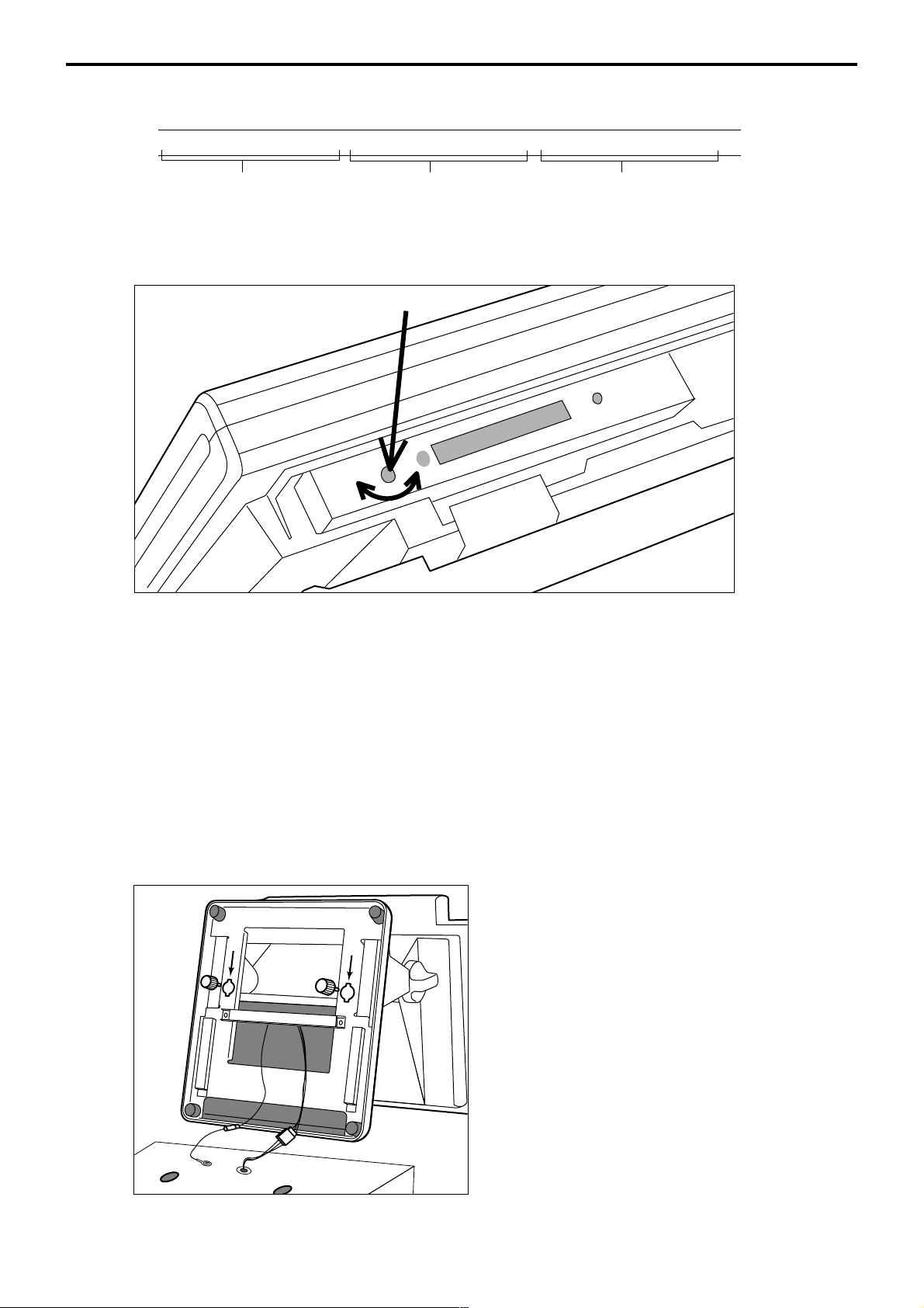
1-5. Cash drawer
Connect the drawer.
Mount the cash register.
In case of connecting drawer, follow the procedure below.
1. Connect drawer connector (three color lead on drawer) to the terminal.
2. Connect frame drawer connector (green lead on drawer) to the terminal.
1. Screw in 2 fixing screws bottom side of the terminal.
2. Mount the terminal on the top of the drawer, ensuring that the feet on the bottom of the
terminal go into the holes on the drawer.
R-14
Page 15
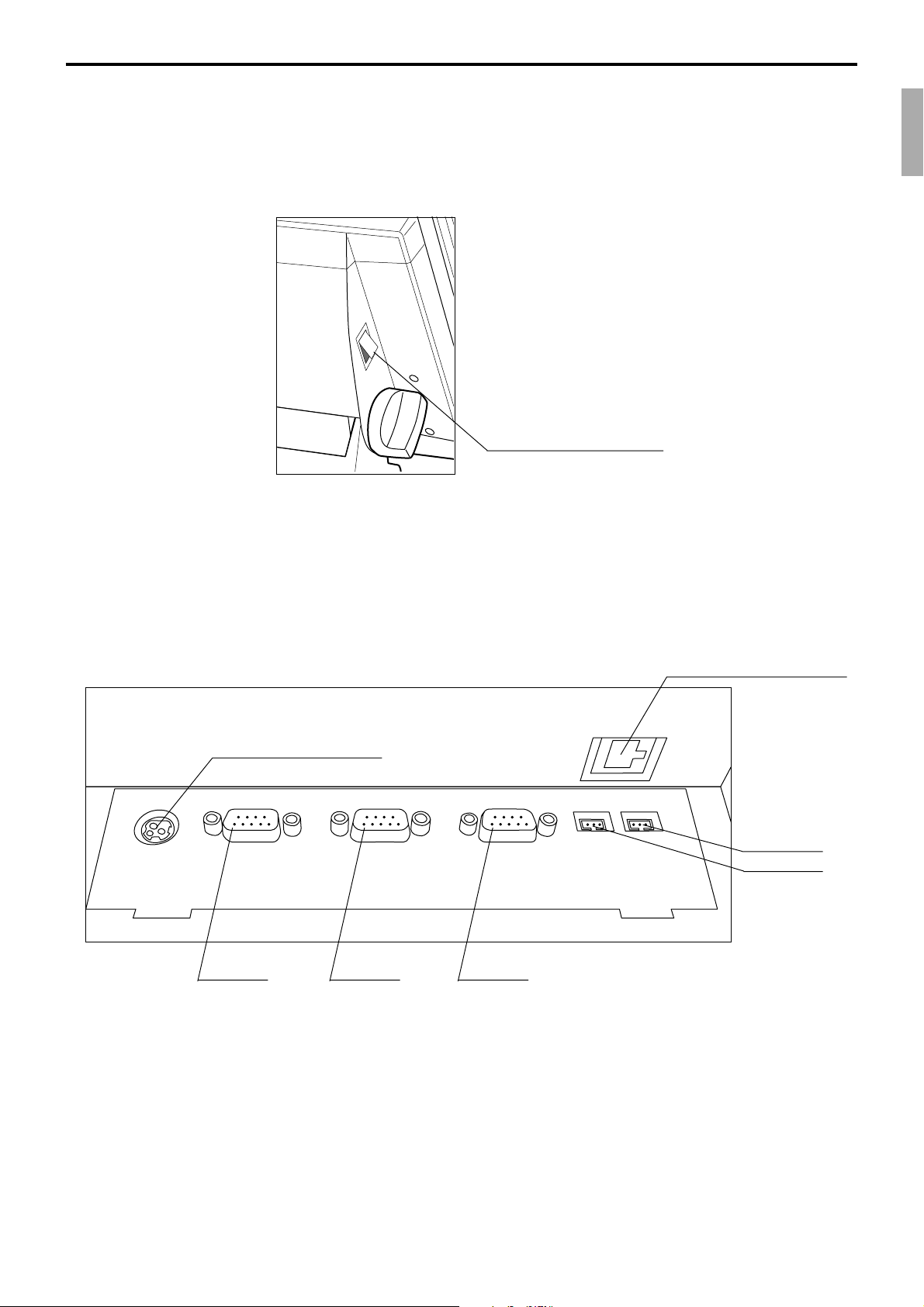
1-6. Input/output connectors
Power switch
Main power switch is located in the power switch cover.
Power switch cover
Input /output connectors
Inline connector, COM port, and drawer cable are located in the bottom connector cover.
Bottom side of the terminal
From the AC adaptor
DC IN
PC/MODEM
COM1
COM1 COM2 COM3
SCANNER
COM2
DISPLAY
COM3
LAN1
DRW1
Inline (10/100Base-T)
DRW2
Drawer 2
Drawer 1
QT-6100 Reference Manual
R-15
Page 16

Hardware Configuration
1-7. Optional peripherals
The following optional peripherals can be used by plugging them into the appropriate port.
1) Personal computer / MODEM: RS-232C COM 1 port
2) Scanner: RS-232C COM 2 port
3) Remote display (QT-6060D) : RS-232C COM 3 port
4) Remote printer (UP-360): RS-232C COM 1 ~ 3 port
The remote printer is used for reports/kitchen orders/receipts.
5) Slip printer (SP-1300) : RS-232C COM 2 or 3 port
SP-1300 can not be connected to COM 1 port.
6) Inline: Inline port
You can use CAT5 UTP cable.
7) Drawer: drawer port
8) CF card: CF card slot (in the card slot cover)
R-16
Page 17
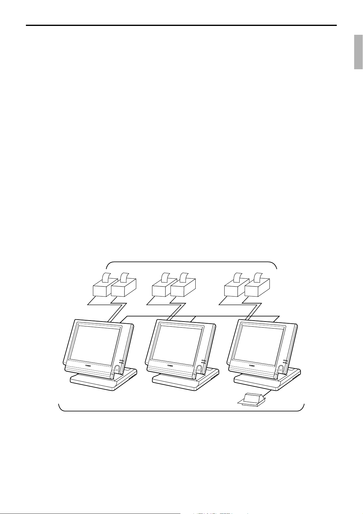
1-8. System configuration
This section represents the system configuration of the QT-6100. The QT-6100 have three
different system configurations, such as shared check tracking / floating clerk interrupt
system, Inline collection / consolidation system and Online collection / consolidation
system.
Before detail explanation, we should define the words:
1) Check master:
Check master is the master server of shared check tracking system and floating clerk
interrupt system. This terminal has check index and detail files and controls them.
2) Check backup master:
Check backup master is the backup server of shared check tracking system and floating
clerk interrupt system. This terminal also has check index and detail files and update
them at the same timing of master.
When the check master goes down, the backup master plays the role of check master.
3) Check self master:
Check self master has its check tracking system files and clerk interrupt files for itself.
4) Satellite:
The terminal which is not assigned to 1) ~ 3) above.
5) Remote printer:
Remote printer prints data sent from both its own terminal and other terminal of the
system.
6) Local printer:
Local printer prints data sent from its own terminal.
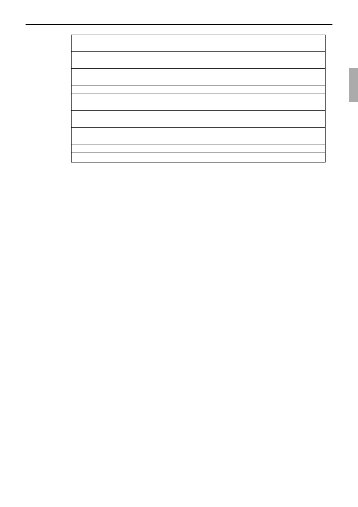
1-9-1. Shared check tracking system/floating clerk interrupt system
Up to 6 remote printers
OrderOrder
PRN (1) PRN (2)
PRN (1) PRN (2)
CHK/BM
OrderOrder
PRN (1) PRN (2)
inline
CHK/M
OrderOrder
Slip
QT-6100 Reference Manual
Up to 3 terminals
R-17
Page 18
Hardware Configuration
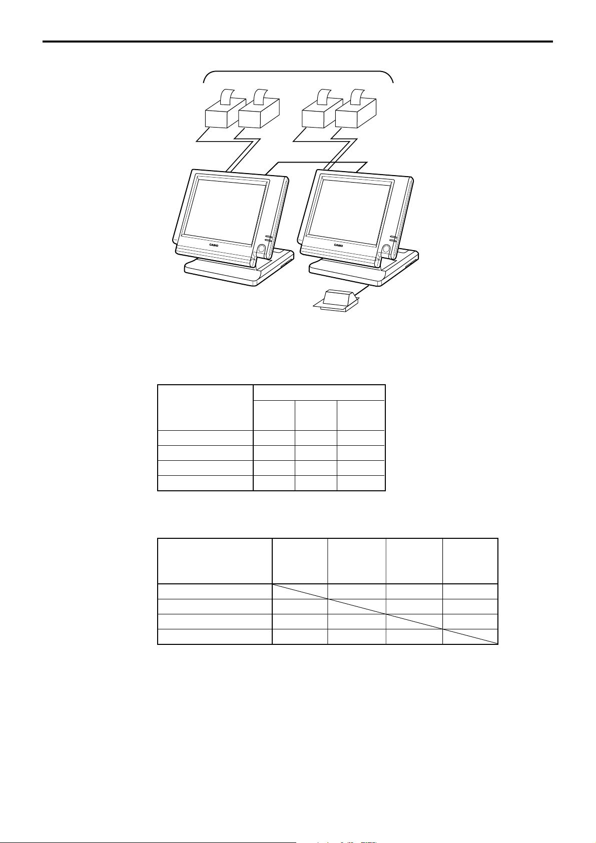
Up to 4 remote printers
OrderOrder
PRN (1) PRN (2)
CHK/MCHK/BM
2 terminals/system
Available peripherals versus ECR definition
✓: Available
Peripherals
ECR definition Remote Slip PC/
printer printer
OrderOrder
PRN (1) PRN (2)
Slip
MODEM
Check master ✔✔✔
Check backup master ✔✔✔
Self master ✔✔✔
Satellite ✔✔✔
Available combinations ECR definition
✓: Available
ECR definition master backup master w/ remote
Check master ✔
Check backup master ✔
Self master ✔
Terminal w/ remote printer ✔✔✔
Note:
1) Please follow the system recommendation above. Otherwise the system performance
may be slow down.
Check Check Self Terminal
master printer
R-18
Page 19
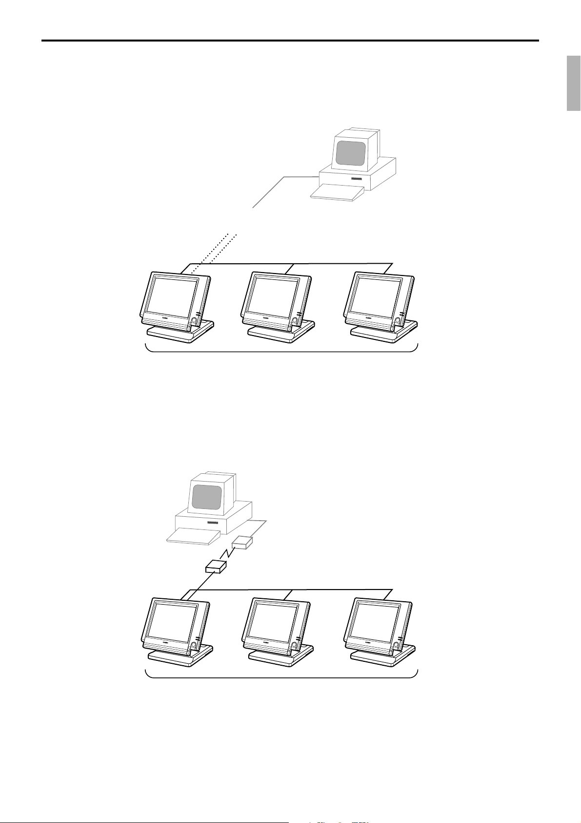
1-8-2. Inline collection/consolidation system
• Inline collection/consolidation and auto-programming for up to 3 terminals.
Note: Maximum 2 remote printers in the 1 terminal system, 4 remote printers / 2 terminal system,
6 remote printers in the 3 terminal can be defined.
PC
Via COM 1 port of the master terminal or Inline
Maximum 3 terminals
1-8-3. Online collection / consolidation system
• Online collection / consolidation and auto-programming for up to 3 terminals.
Note: Maximum 2 remote printers in the 1 terminal system, 4 remote printers / 2 terminal system,
6 remote printers in the 3 terminal can be defined.
PC
on-line (Public / Private Telephone line)
QT-6100 Reference Manual
Maximum 3 terminals
R-19
Page 20
Hardware Configuration
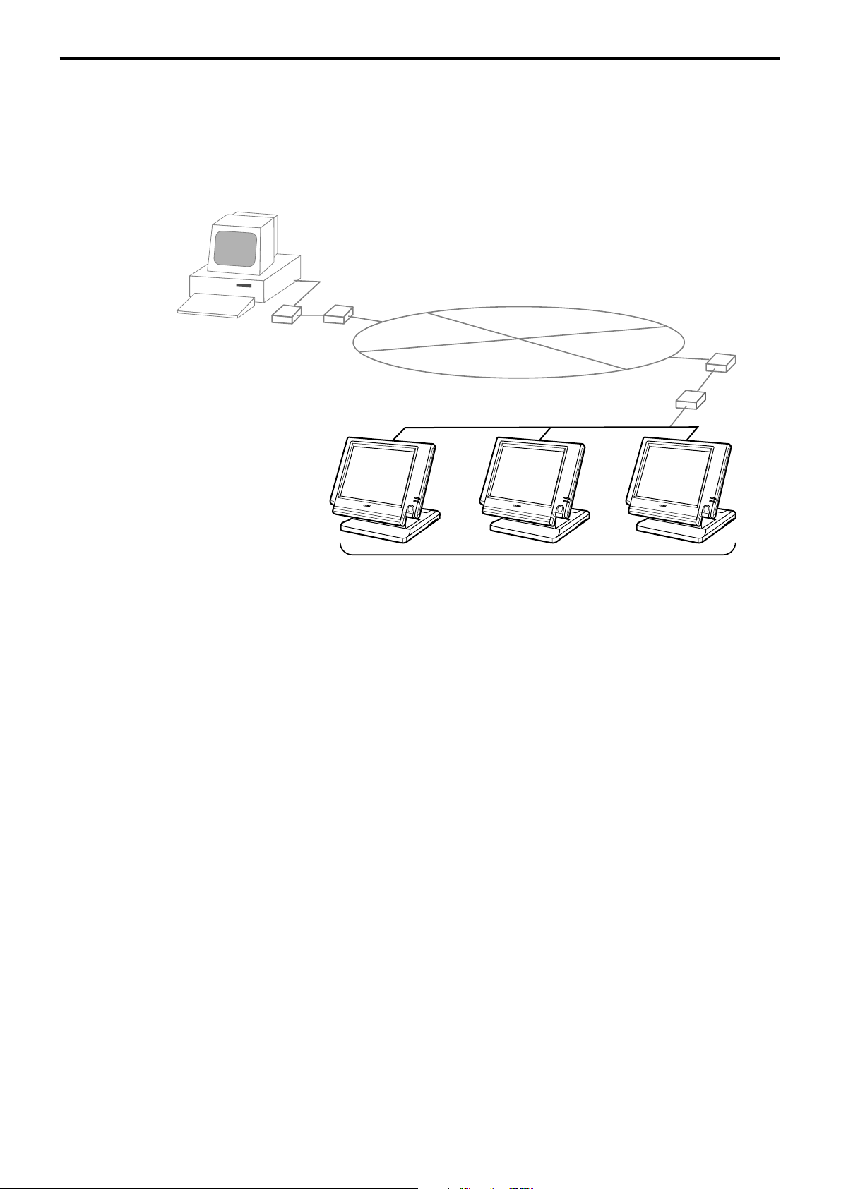
1-8-4. Online collection / consolidation system (use FTP feature)
• Online collection / consolidation and auto-programming for up to 3 terminals.
Note: Maximum 2 remote printers in the 1 terminal system, 4 remote printers / 2 terminal system,
6 remote printers in the 3 terminal can be defined.
ADSL/FTTH
PC
VPN router
MODEM
Internet
ADSL/FTTH
MODEM
VPN router
Maximum 3 terminals
R-20
Page 21

2. Application systems............................................................................ R-23
2-1. General description of application system ....................................... R-23
2-1-1. File concept................................................................................................... R-23
2-1-2. Linkage of totalizers ...................................................................................... R-24
2-1-3. Function keys ................................................................................................ R-25
2-1-4. Keyboard layout ............................................................................................ R-25
2-1-5. Mode control ................................................................................................. R-25
2-1-6. Operation prompt and error messages ......................................................... R-26
2-1-7. Printing control system.................................................................................. R-26
2-2. General description of individual function keys ............................... R-29
2-2-1. System keys.................................................................................................. R-29
2-2-2. Finalize keys ................................................................................................. R-30
2-2-3. Transaction keys ........................................................................................... R-30
2-3. Remote printer control ........................................................................ R-38
2-3-1. Remote printer system configuration ............................................................ R-38
2-3-2. Remote printer control setting....................................................................... R-39
2-3-3. Remote printer output control ....................................................................... R-40
2-3-4. Remote printer backup processes ................................................................ R-40
2-4. Check tracking system ........................................................................ R-43
2-4-1. Shared check tracking system ...................................................................... R-43
2-4-2. Shared check tracking requirement .............................................................. R-44
2-4-3. Data backup when the master goes down .................................................... R-44
2-5. Other check tracking system control ................................................. R-45
2-5-1. The timing to clear check detail and index file after finalization .................... R-45
2-5-2. Table transfer ................................................................................................ R-45
2-5-3. Store and recall............................................................................................. R-45
2-6. Clerk control function ......................................................................... R-47
2-6-1. Clerk interrupt ............................................................................................... R-47
2-6-2. Clerk detail memory ...................................................................................... R-48
2-6-3. Clerk training................................................................................................. R-48
2-6-4. Manager mode control .................................................................................. R-48
2-7. Arrangement key function and scheduler ......................................... R-50
2-7-1. Arrangement key function ............................................................................. R-50
2-7-2. Arrangement program example .................................................................... R-54
2-7-3. Scheduled execution of arrangement key function ....................................... R-54
2-8. Making graphic logo ............................................................................ R-55
2-8-1. About graphic logo ........................................................................................ R-55
2-8-2. Making graphic logo procedure..................................................................... R-55
2-9. Hourly item ........................................................................................... R-56
2-9-1. Programming necessary files before using hourly item function................... R-56
2-10. Time and attendance ........................................................................... R-57
2-10-1. Corresponding relations of the file ................................................................ R-58
2-10-2. Clock-in operation ......................................................................................... R-60
2-10-3. Clock-out operation ....................................................................................... R-63
QT-6100 Reference Manual
R-21
Page 22

Application System
2-11. Sign on control .................................................................................... R-65
2-11-1. Sign on .......................................................................................................... R-65
2-11-2. Solution to abnormality of master terminal ................................................... R-66
2-11-3. Solution to abnormality of satellite terminal .................................................. R-66
2-11-4. Sign on compulsory ...................................................................................... R-66
2-12. IDC (Item Data Capture) ...................................................................... R-67
2-12-1. Available capturing items .............................................................................. R-67
2-12-2. Set up the IDC start / end ............................................................................. R-70
2-12-3. How to memorize the captured items ........................................................... R-71
2-12-4. IDC data file structure ................................................................................... R-72
2-12-5. IDC data type ................................................................................................ R-76
2-12-6. Transferring IDC ............................................................................................ R-77
2-13. Electronic journal ................................................................................ R-78
2-13-1. Storing electronic journal .............................................................................. R-78
2-13-2. Issuing electronic journal report .................................................................... R-78
2-13-3. Displaying electronic journal and producing guest receipts after sales ........ R-78
2-13-4. Transferring electronic journal memory ......................................................... R-79
R-22
Page 23

2. Application systems
This section describes the configuration of application system and their related setting with
the QT-6100. Reading this section provides a general understanding of the overall system
of the terminal.
2-1. General description of application system
2-1-1. File concept
Programming data for each function, as well as registration data, are assigned and handled
in the RAM of the terminal in data blocks called files. Each files identified by a 3-digit file
number consists of multiple records.
Memory management on a file basis allows flexibility memory allocation in accordance
with the application of a specific terminal. The number of records per file can be
programmed, and a file can even be programmed for zero records.
There are three types of files:
– Terminal files:
Terminal files include system work files, daily total files, periodic total 1, periodic total
2 files, buffer files, and program files. Periodic total files have only totalizer field, and
totalize the same data which is accumulated to terminal files at the same time. The
periodic total 1 files have 100 order file numbers, and the periodic total 2 files have 200
order file numbers.
These files can be reset individually and separately from the terminal files. This
provides access to weekly and monthly total data. The periodic total 1 files and 2 files
have the same functions, and can accumulate data with different periods. The same
number of records as the corresponding terminal file must be reserved for each periodic
total files.
– Consolidation files:
Consolidation files are work files for consolidation of daily total, periodic 1 total and
periodic 2 total data from each terminal, and have 300, 400 and 500 order file numbers,
respectively. The same number of records as the corresponding terminal files must be
reserved for each file, on the master terminal.
– Consolidation work files:
Consolidation work files are work files for collection/consolidation of daily, periodic
1/2 data from each terminal. The files have 600 order file numbers.
The file number of records as the corresponding terminal file must be reserved for each
consolidation file.
Each file requires an internal work area, so calculation of actual file size can be performed
using the following formula:
Record length × Number of records + Work area = Actual file size
The table on the page 14 ~ 17 of the programming manual shows all the files available for
the terminal. See the Appendix A-2 of this manual for detail formats of individual files.
QT-6100 Reference Manual
R-23
Page 24
Application System
2-1-2. Linkage of totalizers
Registered data is accumulated to totalizers which are reserved for each functions.
The QT-6100 has the following types of totalizers:
1) Fixed totalizers
Registration data is accumulated for individual terminals.
2) Function key totalizers
Data input by finalize or transaction keys is accumulated in totalizers for each key.
Operation types, as well as data used in operation differ depending on the key.
3) Subdepartment totalizers
Registration data is accumulated in totalizers for each subdepartment.
4) Department totalizers
Registration data is accumulated in totalizers for each department.
5) Group totalizers
Registration data is accumulated in totalizers for each group.
6) PLU totalizers
Registration data is accumulated in totalizers for each PLU.
7) Clerk totalizers
Registration data is accumulated for each relevant clerk. A clerk detail totalizer can be
linked to a fix totalizer, finalize key, transaction key, or item totalizer (department /
PLU / subdepartment / group), and accumulate data registered for the destination
totalizer of each relevant clerk.
8) Other totalizer
Functions for hourly sales, monthly sales void reason, table analysis, time attendance
and hourly item also have totalizers.
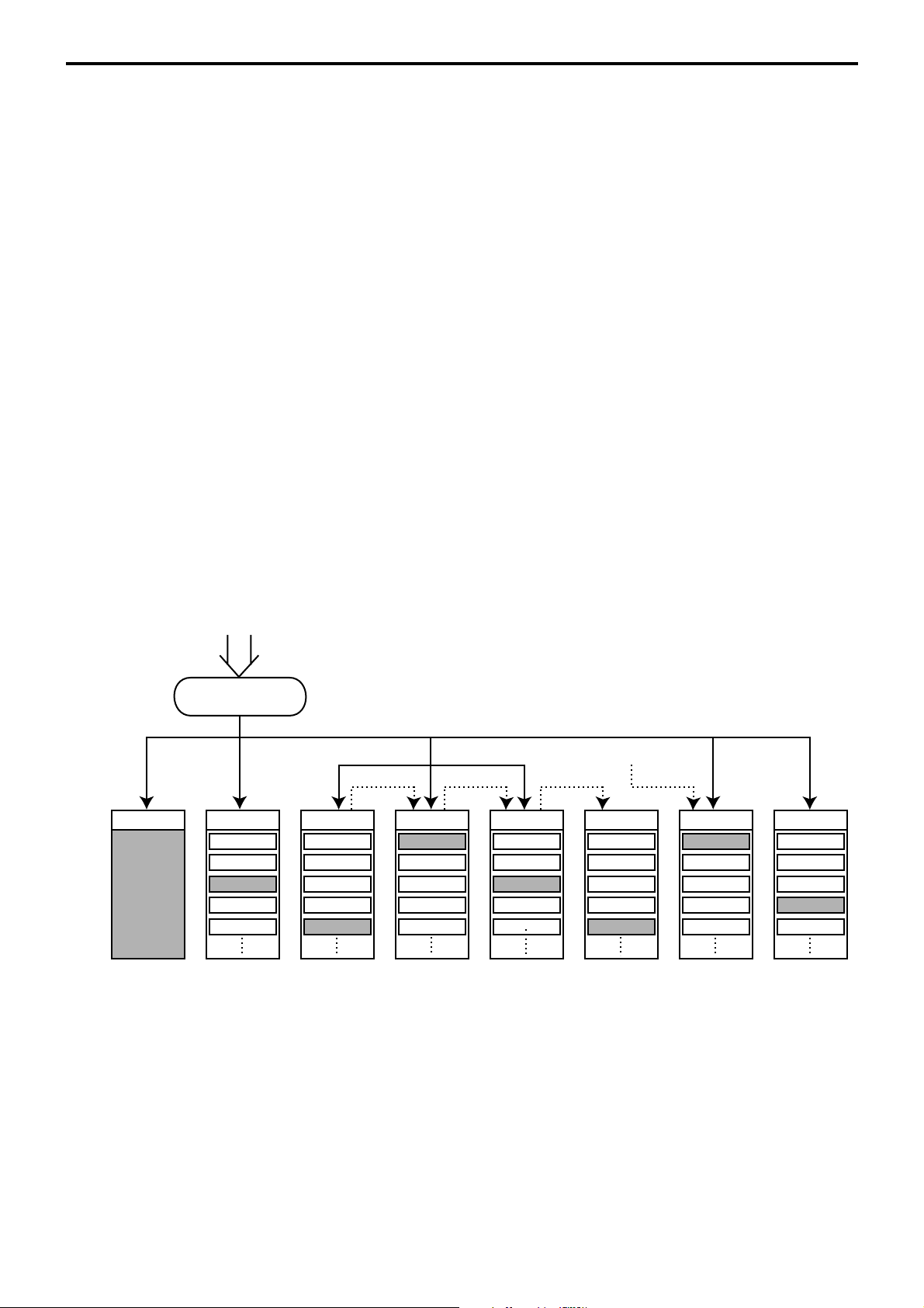
Registration data flow
Registration
Calculation
*2
*1 *1 *1
Fixed totalizer PLU file Subdept. file Dept. file Group file
Function key
totalizer
*1
*2
Linking between PLUs, subdepartments, departments and groups can be programmed
to meet the needs of the retail environment.
PLUs can be programmed to link with subdepartments, departments or group, while
subdepartment can be programmed to link with department or group, and department
can be programmed to link with group.
When a PLU is programmed to link with a department, data registered for the PLU is
also accumulated to the department. In addition, when the department is programmed
to link with a group, data registered for the PLU is simultaneously reflected the
department totalizer and group totalizer.
When data is registered to a totalizer which is preset in the clerk detail link table, the
data is also accumulated to the clerk detail totalizer reserved for each relevant clerk.
Clerk detail file
Other file
R-24
Page 25

2-1-3. Function keys
The keys on the keyboard can be assigned various functions that are used for registration
as required for the terminal. For convenience sake, these functions are called by function
keys.
There are two types of function keys:
1) System keys
Numeric keys, clear key, home position key, left / right / up / down arrow keys, yes key,
no key, mode selection keys, ESC/SKIP key, page up / down key are system keys.
2) Function keys
These function keys are used for finalize a transaction, to specify the functions for a
registration or to specify the meaning of a entry. These function keys have programmable functions, which are set to the transaction key / department / subdepartment /
PLU file.
Function keys include finalize key, transaction key, department key, subdepartment
key and flat PLU key.
The list of all function keys is shown in the Program 4 chapter of the programming manual.
General descriptions of individual function keys are found in the chapter 2-2.
2-1-4. Keyboard layout
Normally, the keyboard is assigned functions which are required for registration of
transactions. The keyboard is also used for character input when entering descriptors or
names during programming.
The QT-6100 automatically switches the keyboard to its character input function when it
determines that character input is required for the operation sequence you are performing.
This means that you can input characters without having to worry about manually changing
the keyboard input mode.
The function key (except system keys) allocation is fully programmable to meet the
specific needs of each terminal. The actual programming of key layouts can be performed
in the PGM4 mode, and programmed data is written onto the key table (file 074/174).
The allocation can also be programmed when programming each function file for
programming function keys such as finalize keys, transaction keys, department keys,
subdepartment keys, and flat PLU keys.
Character key layout
Refer to the page 104, 105 of the programming manual.
QT-6100 Reference Manual
R-25
Page 26

Application System
2-1-5. Mode control
With the QT-6100, each clerk can be programmed to enable or disable operations in the
following modes:
– REF mode
– REG– mode
– REG mode
– X/Z mode
– Program 1 ~ 6 mode
– Manager mode
– Inline X/Z mode
– Inline auto program
– CF backup / restore mode
Also, each clerk can be programmed to enable or disable operations of every function key.
Though the terminal has no actual REG 2 mode, on the page 48 in the Clerk Control
function chapter of this manual, the manager control procedure is described.
Arrangement execution mode programmed in the arrangement key ignores the mode
control program by the clerk.
Please note that if a clerk want to operate an arrangement, he / she should allow to operate
arrangement function.
2-1-6. Operation prompt and error messages
The QT-6100 displays messages to indicate the status of the terminal being operated or
programmed. These messages help to determine the status of the terminal or the required
subsequent action.
2-1-6-1. Operation prompt
Refer to the page 201 of this manual for details. These messages cannot be added, modified
or deleted.
2-1-6-2. Error messages
Refer to the page 198 ~ 200 of this manual for details. Error messages are displayed to
indicate that an error has occurred and a compulsory operation must be performed. All error
messages cannot be added, modified or deleted.
2-1-7. Printing control system
The following describes the control system for printing of receipts, the journal, validation,
slips and X/Z reports.
2-1-7-1. Receipt print control during normal registration
Normally, the receipt is printed to reflect the details of a registration as it is performed, with
the receipt being issued with the finalize operation. By using the <RECEIPT ON/OFF>
key, the receipt issuance status can be turned off to suspend printing and issuance of
receipts when so desired. Pressing the <RECEIPT ON/OFF> key turns the receipt
issuance status on or off, and when the receipt issuance status is On, the icon “RECEIPT
ON” appears.
R-26
The following programming can be performed for receipt printing:
Page 27
Description Program location
Receipt “Item consolidation” PGM3; Machine Control3 in General Feature
Receipt “Sort by group, department” PGM3; Machine Control3 in General Feature
Print consecutive number on the receipt PGM3; Machine Control3 in General Feature
Print date / time on the receipt PGM3; Machine Control3 in General Feature
Vertical double character PGM3; Machine Control3 in General Feature
Set menu detail on guest / slip PGM3; Print Control in General Feature
Print PLU number PGM3; Print Control in General Feature
Print finalized total PGM3; Print Control in General Feature
Print taxable amount PGM3; Print Control in General Feature
Print taxable status PGM3; Print Control in General Feature
Print total number of item sold PGM3; Print Control in General Feature
Print customer number (number of covers) PGM3; Print Control in General Feature
One line feed after finalization PGM3; Print Control in General Feature
Time format (24H / 12H) PGM3; Print Control in General Feature
2-1-7-2. Validation print control
The QT-6100 allows use of the slip printer (SP-1300) for validation printing of item
registrations, function registrations and sales totals. To perform validation printing, insert
the validation paper into the slip printer, and then press the <VALIDATION> key
(function code 037).
The following desctription shows the print format for validation performed using the slip
printer.
There are three general types of validation printing:
1) Finalization validation
2) Transaction validation
3) Item validation
Finalization validation is performed following finalization operations with finalize keys.
When a validation is performed following receipt issuance, the sales total or tendered
amount is printed, while partial tendering, the tendered amount for the specified medium
is printed.
Transaction validation is valid for the following function keys:
– Received on account, Paid out, finalization of Pick up or Loan, Check cashing, Minus,
Plus, Discount, Premium, Void, Coupon, Coupon2, Tip, Deposit, Subtotal, Merchandise subtotal keys
You can program the allowable number of validation printings or multiple validation
printing status for the above listed keys.
Also some of these keys can be programmed as validation compulsory, this means that
registration is not permitted until the validation of the former registration has been
performed.
Item validation is performed directly following an item registration listed below.
– Departments
– Subdepartments
– PLUs
You can program the multiple validation printing status for above items.
QT-6100 Reference Manual
R-27
Page 28

Application System
2-1-7-3. Slip print control
Connection of an optional slip printer (SP-1300) to the QT-6100 makes it possible to print
transaction details on a slip.
To print a slip, insert a slip paper into the printer, and adjust paper position by entering the
number of printed lines and pressing the <SLIP FEED/RELEASE> key (function code
056) or the <SLIP BACK FEED/RELEASE> key (function code 054) and then press the
<SLIP PRINT> key (function code 055). Or it is possible to find the appropriate slip
printing start line automatically.
After printing a slip, the paper is automatically released.
If the paper is not released for some reasons, press <SLIP FEED/RELEASE> or <SLIP
BACK FEED/RELEASE> to release the paper.
Before using slip printer, you should program the maximum lines of slip.
The following two sections are other features to control slip printing format:
2-1-7-4. Endorsement message print control
The QT-6100 allows printing of endorsement messages on the slip printer (SP-1300) for
check registrations. To perform endorsement message printing, insert the paper into the
slip printer following finalization using the <CHECK> key or check cashing transaction
using the <CHECK> key, and press the following key:
– Endorsement key (function code 039)
Check key and check cashing key can be programmed for compulsory endorsement print.
The endorsement message contents should be programmed into the endorsement message
file (file 033).
2-1-7-5. Check printing print control
The QT-6100 allows printing check tendered amount on a check inserted into the slip
printer. To perform check printing, insert the paper into the slip printer following check
finalization using the <CHECK> key, and press the following key:
– Check print key (function code 012)
Check key can be programmed for compulsory check print. The check printing format is
controlled by the check print file (file 041).
2-1-7-6. X/Z report print control
The QT-6100 can output a report in the read (X) or reset (Z) mode. The following shows
the programming for X/Z print controls:
Description Program location
Items on the fixed totalizer report PGM3; Report Control1 in General Feature
Items zero skip PGM3; Report Control2 in General Feature
Average spend/item on monthly report PGM3; Report Control2 in General Feature
PLU order (memory / random code) PGM3; Report Control2 in General Feature
Print / Non print PLU No. on PLU report PGM3; Report Control2 in General Feature
Print / Non print Sales ratio PGM3; Report Control2 in General Feature
Print / Non print Z counter PGM3; Report Control2 in General Feature
Print / Non print Item discount totalizer PGM3; Report Control2 in General Feature
Print GT PGM3; Report Control2 in General Feature
R-28
Page 29

2-2. General description of individual function keys
This section describes individual function key that can be assigned to the keys on the
keyboard of QT-6100.
2-2-1. System keys
The system key consist on a non-programmable function key.
The following system keys are available.
1) Numeric keys (0, 1 ~ 9, 00, 000, decimal point)
These keys are used for inputting numerical data such as PLU codes, amounts, quantities,
etc. These keys must be allocated on the keyboard.
2) Clear key
This key is used for clearing numerical values after they have been input, and after incorrect
function keys have been pressed. This key also can be used to clear errors. This key must
be allocated on the keyboard.
3) Home position key
This key is used for returning cursor to the home position.
4) Left, right, up, down arrow keys
These keys are used for moving the cursor.
5) Yes key
This key is used for consenting the selection and proceeding steps.
6) No key
This key is used for cancelling the selection and proceeding steps.
7) Mode key
This key is used for changing modes of the terminal. This key shows the allowable mode
keys in the mode pop-up window.
8) ESC/SKIP key
This key is used for terminating a programming sequence, X/Z sequence, and returning the
former window. This key is also used for terminating a report being issued in PGM, X, and
Z mode.
9) Display on/off key
This key is used for turning on / off the terminal.
10) Page up key
This key is used for turning the window forwards.
11) Page down key
This key is used for turning the window backwards.
QT-6100 Reference Manual
R-29
Page 30

Application System
2-2-2. Finalize keys
This section covers the general description of each finalize key, with its respective options.
Finalize keys have programmable functions which may be used as required.
1) Tender key
This key is used for finalizing transactions. Up to six media in drawer totalizers are
reserved in the fixed totalizer file, and cash key is linked to cash in drawer, charge key to
charge in drawer, check key to check in drawer and credit key to credit in drawer, food
stamp tender key to food stamp in drawer, EBT tender key to EBT in drawer.
When this key is pressed, the total amount of the transaction is calculated. Normally, a
receipt is issued and the drawer opens at the same time. The total amount is added to the
appropriate totalizers and counters, with consecutive numbers being increased by one.
When an amount exceeding the sales amount is received, the change is calculated,
displayed and printed on the receipt.
This key can also be used in combination with other finalize keys for partial tender and can
also be used to specify the type of media during loan, pick up or media change operation.
Programmability: Refer to page 83, 84 of the programming manual.
2) New balance key
This key is used for adding the latest registered total amount to the previous balance to
obtain a new balance.
When this key is pressed, the total amount of the transaction is calculated. Normally, a
receipt is issued.
Programmability: Refer to page 84 of the programming manual.
2-2-3. Transaction keys
Each of the transaction keys have programmable functions which may be used as required.
The general description of each transaction key, with individual options, is outlined on the
following sections.
1) Price inquiry key (Function code 008)
This key is used to confirm the price and descriptors of PLU without registering.
2) Stock inquiry key (Function code 009)
This key is used to confirm the stock quantity and descriptors of PLU without registering.
3) Text recall key (Function code 010)
This key is used to recall characters.
Programmability: Refer to page 85 of the programming manual.
4) Text print key (Function code 011)
This key is used to print the entered characters.
Programmability: Refer to page 85 of the programming manual.
5) Check print key (Function code 012)
This key is used to print the check on the slip printer (SP-1300). Pressing this key allows
the selection from the following list to print on a check.
1. Check amount in Arabic numerals (normal size / double size)
2. Date (normal size / double size)
3. Check print message in the check endorsement message file
This item noted above can be arranged into a check print format according to the needs
of the store. Check printing using this key is valid only for the following operation of the
check key.
Programmability: Refer to page 85 of the programming manual.
6) Clerk transfer key (Function code 013)
This key is used to transfer opened checks to another clerk.
Programmability: Refer to page 86 of the programming manual.
R-30
Page 31

7) Table transfer key (Function code 014)
This key is used to transfer the contents of a check to another check.
Programmability: Refer to page 86 of the programming manual.
8) Tip key (Function code 015)
This key is used to register tips.
Programmability: Refer to page 87 of the programming manual.
9) Normal receipt key (Function code 016)
This key is used to change the order status from Bon to normal and from single item sales
to normal.
10) Loan key (Function code 019)
This key inputs the amount of money provided for making change. This operation affects
media totals, rather than sales totals.
Loans are made for all types of money which can be specified by finalize keys.
Programmability: Refer to page 87 of the programming manual.
11) Received on account key (Function code 020)
This key is used to register amounts received for purposes other than sales transactions.
This transaction affects media totals, rather than sales totals.
Programmability: Refer to page 87 of the programming manual.
12) Paid out/Euro key (Function code 021)
This key is used to register amounts of paid outs from the terminal. This transaction affects
media totals, rather than sales totals. If the terminal has the file 099 (Euro program file),
this key also works as “Euro” key. Euro key has the following features: (1) Converting the
main currency to the sub currency, when registering a subtotal amount. (2) Specifying sub
currency while entering an amount for payment.
Programmability: Refer to page 87 of the programming manual.
13) Pick up key (Function code 022)
When sales receipts are removed from the drawer or when the amount in-drawer exceeds
the limit value (sentinel function), the manager performs a pick up operation. This key is
used for this function. This operation affects media totals, rather than sales totals.
Pick ups are made for all types of money which can be specified by finalize keys.
Programmability: Refer to page 87 of the programming manual.
14) Coupon key (Function code 023)
This key is used for registering coupons. This operation affects the coupon amount in the
coupon totalizers. The registered coupon amounts is not deducted from the department,
PLU or gross totalizers, but from the net totalizers only. (selecting GROSS specification)
Programmability: Refer to page 88 of the programming manual.
15) Deposit key (Function code 025)
This key is used to register deposits.
Programmability: Refer to page 89 of the programming manual.
16) Minus key (Function code 027)
This key is used to register subtraction. This operation affects the subtraction amount in
the minus key totalizers. The registered amounts is not deducted from the department, PLU
or gross totalizers, but from the net totalizers only. (selecting GROSS specification)
Programmability: Refer to page 88 of the programming manual.
17) Discount key (Function code 028)
This key applies a preset % or manual input % to obtain the discount amount for the last
registered item or subtotal.
Programmability: Refer to page 90 of the programming manual.
QT-6100 Reference Manual
R-31
Page 32

Application System
18) Plus key (Function code 029)
This key is used for registering surcharge. This operation affects the surcharge amount in
the plus key totalizers. The registered amounts is not added to the department, PLU or gross
totalizers, but from the net totalizers only. (selecting GROSS specification)
Programmability: Refer to page 88 of the programming manual.
19) Premium key (Function code 030)
This key applies a preset % or manual input % to obtain the premium amount for the last
registered item or subtotal.
Programmability: Refer to page 90 of the programming manual.
20) Refund key (Function code 033)
This key declares next input for a return money.
Programmability: Refer to page 100 of the programming manual.
21) Error correct/Void key (Function code 034)
This key is used to correct the last registered item, discount, premium, partial tendered, etc.
This key also invalidates proceeding data registered for departments subdepartments,
PLUs or set menus only.
Programmability: Refer to page 89 of the programming manual.
22) Coupon 2 key (Function code 036)
This key is used to register coupons. The registered coupon amounts is deducted from the
department, subdepartment, PLU or gross totalizers and the net totalizers.
23) Validation key (Function code 037)
This key validates item or transaction amounts on slips. Validation can be made compulsory
for certain function keys. Multiple validation can be prohibited for certain function keys.
24) Receipt key (Function code 038)
This key issues a receipt for the last transaction (post-finalization receipt) when the original
receipt is not issued. This key also issues a guest receipt. The guest receipt can be
designated by seat number.
Programmability: Refer to page 91 of the programming manual.
25) Check endorsement key (Function code 039)
This key is used to print a preset check endorsement using the slip printer.
Programmability: Refer to page 89 of the programming manual.
26) Non-add key (Function code 040)
This key prints reference numbers (personal check number, card number etc.)
Programmability: Refer to page 91 of the programming manual.
27) Non-add / No sale key (Function code 041)
This key prints reference numbers (personal check number, card number etc.)
This key also opens the drawer between transaction.
Programmability: Refer to page 91 of the programming manual.
28) No sale key (Function code 042)
This key opens the drawer between transaction.
29) Number of customer key (Function code 043)
This key registers the number of customers.
Programmability: Refer to page 92 of the programming manual.
30) Arrangement key (Function code 044)
This key is used to activate an arrangement program programmed in the arrangement
file. Any operation that can be performed from the keyboard, as well as mode, can be
programmed in an arrangement program, and can be performed merely by pressing this
key.
The mode control function of this key can be programmed for all modes.
Programmability: Refer to page 92 of the programming manual.
R-32
Page 33

31) Currency exchange key (Function code 045)
This key converts foreign currency to local currency or vice versa using the exchange rate
preset for the key and displays the result.
This key is used for conversions of a home currency subtotal or merchandise subtotal to
equivalent of another country's currency.
This key is also used for conversion of another country's currency payment to the equivalent
of the home currency.
Programmability: Refer to page 93 of the programming manual.
32) VAT key (Function code 046)
This key is used to print VAT breakdowns.
33) Bill copy key (Function code 047)
This key is used to issue bill copy.
34) PLU key (Function code 048)
This key is used to enter PLU numbers.
35) Price key (Function code 049)
This key is used in the following transactions to enter a unit price.
– Department registration using the department number key
– Subdepartment registration using the subdepartment number key
– Open PLU registration
In case of the department or subdepartment registration mentioned above, the Price key is
pressed after entering the unit price to override a unit price preset to the department or
subdepartment. If the preset price is to be registered as it is, simply press the Price key.
36) Department key (Function code 051)
This key is used to register items for a department.
Programmability: Refer to page 80 of the programming manual.
37) Slip back feed / Release key (Function code 054)
This key is used to back feed slips inserted into the slip printer. This is done by specifying
the number of feed lines. This key is also used to release the slip paper holder if numbers
are not entered.
38) Slip print key (Function code 055)
This key is used to execute a slip batch printing on the slip printer. Pressing this key prints
the sales details. Actual printing is performed following receipt issuance.
Programmability: Refer to page 93 of the programming manual.
39) Slip feed / Release key (Function code 056)
This key is used to feed slips inserted into the slip printer. This is done by specifying the
number of feed lines. This key is also used to release the slip paper holder if numbers are
not entered.
40) Tax status shift key (Function code 057)
This key activates tax table which is specified by the tax status programmed for this key.
The tax status is programmed for the departments, subdepartments, PLUs, minus, plus,
discount and premium keys. Pressing this key during registration converts taxable item to
non taxable, and non taxable item to taxable.
Programmability: Refer to page 93 of the programming manual.
41) Table number key (Function code 058)
This key is used to input table numbers.
42) Food stamp status shift key (Function code 059)
The food stamp status is programmed for the departments, subdepartments, PLUs, minus,
plus, discount and premium keys. Pressing this key during registration converts food
stampable item to non stampable, and non stampable item to stampable.
QT-6100 Reference Manual
R-33
Page 34

Application System
43) Tax exempt key (Function code 062)
This key is used to change taxable amounts to nontaxable amounts. This key works adding
on a tax system only.
Programmability: Refer to page 97 of the programming manual.
44) Flat PLU key (Function code 063)
This key is used to register items to flat PLU.
Programmability: Refer to page 78 of the programming manual.
45) Menu shift key (Function code 064)
This key is used to shift Flat PLU key to the n-th (n = 1 ~ 8) menu.
Programmability: Refer to page 99 of the programming manual.
46) Shift PLU key (Function code 065)
This key is used to shift a Flat PLU key to the n-th (n = 1 ~ 8) level.
Programmability: Refer to page 99 of the programming manual.
47) Open key (Function code 067)
This key is used to release the maximum amount limit or low digit limit (programmable)
for an amount which exceeds the limit.
Programmability: Refer to page 94 of the programming manual.
48) Open 2 key (Function code 068)
This key is used to suspend the compulsory specifications listed below.
Programmability: Refer to page 94 of the programming manual.
49) First unit price key (Function code 069)
This key is used to register a specific item at the first unit price.
50) Second unit price key (Function code 070)
This key is used to register a specific item at the second unit price.
51) Clerk number key (Function code 072)
This key is used to assign a clerk’s secret number.
Programmability: Refer to page 95 of the programming manual.
52) Operator read / reset key (Function code 073)
This key is used to issue a clerk’s individual X/Z report.
Programmability: Refer to page 95 of the programming manual.
53) Tray total key (Function code 074)
This key is used to obtain the sectional subtotal amount.
Programmability: Refer to page 99 of the programming manual.
54) Subtotal key (Function code 075)
This key is used to obtain subtotal amount with add-on tax and previous balance.
Programmability: Refer to page 95 of the programming manual.
55) Receipt On / Off key (Function code 076)
This key is used to change the status “Receipt issue” or “No receipt.”
– Receipt off / Receipt and journal off
56) Taxable amount subtotal key (Function code 077)
This key is used to obtain taxable amount subtotal.
Programmability: Refer to page 93 of the programming manual.
57) Operator number key (Function code 078)
This key is used to enter a clerk number during clerk transfer.
58) Merchandise subtotal key (Function code 080)
This key is used to obtain subtotal excluding the add-on tax amount and the previous
balance.
Programmability: Refer to page 95 of the programming manual.
R-34
Page 35

59) Food stamp subtotal key (Function code 081)
This key is used to obtain food stamp subtotal. This key should be pressed just before
<FOOD STAMP> or <EBT> finalization.
60) Quantity / For key (Function code 083)
This key provides the same functions as the multiplication key. In addition, this key also
has a split pricing function. The function is used to calculate the price per unit for particular
items, which are sold in bulk in order to obtain the total amount for the number of units
purchased.
Programmability: Refer to page 96 of the programming manual.
61) Square key (Function code 084)
This key provides the same functions as the multiplication key. In addition, this key also
has a square multiplication function.
Programmability: Refer to page 96 of the programming manual.
62) Selective item subtotal key (Function code 085)
This key is used to obtain the selective item 1 / 2 subtotal amount.
In addition to the common programming, this key has the following option:
– Selective item status 1 / 2
63) Cube key (Function code 090)
This key provides the same functions as the multiplication key. In addition, this key also
has a cube multiplication function.
Programmability: Refer to page 96 of the programming manual.
64) New check key (Function code 091)
This key is used in a check tracking system to input a new check number in order to open
a new check under that number.
Programmability: Refer to page 98 of the programming manual.
65) Old check key (Function code 092)
This key is used in a check tracking system to input the number of an existing check
(previously created by the New check key) whose details are stored in the check tracking
memory. Existing checks are reopened to perform further registration or to finalize them.
Programmability: Refer to page 99 of the programming manual.
66) New / Old check key (Function code 093)
This key is used in a check tracking system to input check numbers in order to open new
checks and to reopen existing checks. When the clerk inputs a check number, the terminal
checks to see if that number already exists in the check tracking memory. If there is no
matching number in the memory, a new check is opened under the input number. If the
check number input matches a number already stored in the memory, that check is
reopened for further registration or finalization.
Programmability: Refer to page 98 of the programming manual.
67) Add check key (Function code 094)
This key is used in a check tracking system to combine the details of more than one check
into a single check.
68) Separate check key (Function code 095)
This key is used in a check tracking system to separate selected items or to separate by seat
number from one check to another check.
69) OBR (Optical Barcode Reader) key (Function code 103)
This key is used to enter scanning PLU code manually.
70) Clock-in/out key (Function code 108)
This key is used to register the time when employees start/finish their job.
Programmability: Refer to page 97 of the programming manual.
QT-6100 Reference Manual
R-35
Page 36

Application System
71) Break-in / out key (Function code 109)
This key is used to register the starting / finishing time when employees have a recess.
Programmability: Refer to page 97 of the programming manual.
(future use)
72) Coupon number key (Function code 110)
This key is used to enter coupon number for registering mix and match discount.
Programmability: Refer to page 100 of the programming manual.
73) Substitution key (Function code 111)
Replaces group PLU with a PLU not preset in the pulldown menu.
74) Ketten Bon key (Function code 113)
This key is used to enter quantities for multiplication. Multiplication by this key issues
singular order prints.
Programmability: Refer to page 96 of the programming manual.
75) House Bon key (Function code 114)
This key is used to register items for in-store use.
76) Post entry key (Function code 115)
This key is used in a check tracking or clerk interrupt system to indicate the reserved item
of set menu and register it as a fixed item later on.
– Enter post entry
Press this key while the window is opened, the key descriptor appears on the screen and
it is registered as a reserved item.
– Fix post entry
After finishing the set menu registration, move the cursor on to the reserved item, press
this key again, then the appropriate window will be opened to fix it.
77) Round repeat key (Function code 116)
This key is used to register the same items which were ordered just before.
Programmability: Refer to page 98 of the programming manual.
78) Open check key (Function code 117)
This key is used to issue an open check report of an assigned clerk.
Programmability: Refer to page 96 of the programming manual.
79) Media change key (Function code 118)
This key is used to change media in drawer amounts. Pressing this key enters media change
operation.
80) Seat number key (Function code 119)
This key is used to enter and print seat number.
81) Eat-in key (Function code 128)
This key is used to specify if the customer eats in the restaurant. Before closing a
transaction, press this key.
Programmability: Refer to page 98 of the programming manual.
82) Takeout key (Function code 129)
This key is used to specify if the customer takes out items. Before closing a transaction,
press this key for the tax exemption.
Programmability: Refer to page 98 of the programming manual.
83) Store key (Function code 130)
This key is used for storing the check number of the registered items. Allocate this key to
the terminal at the drive-through entrance. When this key is pressed, registered item data
will be stored, and then these data will transfer to the youngest check number.
Programmability: Refer to page 98 of the programming manual.
R-36
Page 37

84) Recall key (Function code 131)
This key is used for recalling the transferred check number by the store key. When you
press this key, the check number will appear in order of the oldest record.
Programmability: Refer to page 99 of the programming manual.
85) Subdepartment key (Function code 133)
This key is used to register items for the subdepartment.
Programmability: Refer to page 79 of the programming manual.
86) Subdepartment number key (Function code 134)
This key is used to enter subdepartment numbers.
87) Department number key (Function code 135)
This key is used to enter department numbers.
88) List key (Function code 136)
This key is used to display menu lists.
Programmability: Refer to page 96 of the programming manual.
89) List number key (Function code 137)
This key is used to designate list number.
90) Dutch account key (Function code 140)
This key is used to share the total payment by customer.
Programmability: Refer to page 99 of the programming manual.
91) Customer ID number key (Function code 148)
This key is used to enter customer ID number.
92) Payment key (Function code 149)
This key is used to declare the following transactions as payment.
93) Electronic journal display key (Function code 207)
This key is used to display the stored journal.
94) Display mode key (Function code 219)
This key is used to change display modes (normal mode/item consolidation mode).
95) Cancel key (Function code 236)
Invalidates all preceding data registered for departments, PLUs and set menus within a
transaction. This key must be pressed before the transaction involving the data to be
invalidated is finalized. It is also effective even after calculation of subtotal amount.
Programmability: Refer to page 96 of the programming manual.
96) Item search key (Function code 246)
Use this key to search an item by its name.
Programmability: Refer to page 100 of the programming manual.
97) Order character change key (Function code 252)
This key is used to change the order character. The order characters not only of the item
but in the order character table can be printed.
Programmability: Refer to page 100 of the programming manual.
98) Location change key (Function code 260)
Use this key to select the pop-up window which shows the table layout of each floor/part
of the restaurant.
Programmability: Refer to page 100 of the programming manual.
99) Table sharing key (Function code 261)
Use this key to assign one table to two or more customer groups.
QT-6100 Reference Manual
R-37
Page 38

Application System
2-3. Remote printer control
Up to eight printers for printing kitchen orders etc.
2-3-1. Remote printer system configuration
Please refer to page 17 for the system configuration.
Up to 6 remote printers
OrderOrder
PRN (1) PRN (2)
PRN (1) PRN (2)
CHK/BM
OrderOrder
PRN (1) PRN (2)
inline
CHK/M
OrderOrder
Slip
Up to 3 terminals
The printing processing of the remote printer is performed as shown in the figure below.
1
QT-6100
QT-6100 QT-6100
Print
buffer
Remote
Printer
R-38
23
1 A transaction is made at a terminal.
2 The terminal sends printing data to the terminal with remote printer.
3 The terminal with remote printer sends data to the remote printer.
Page 39

2-3-2. Remote printer control setting
Remote printer settings:
After changing the DIP switch configuration, remote printer initialization (power on by
pressing the <LF> key) is necessary.
UP-360
Dip switch is located at the bottom of the printer.
SW No. Function
Reset by DTR
1
reserved
2
Protocol
3
4
1
Transmision speed
5
6
Parity
7
undifined
8
Low power comsumption
9
undifined
10
ON OFF
Ye s N o
--- fixed
DTR/DSR XON/XOFF
See transmission
speed setting
See paritysetting
--- ---
Ye s N o
--- ---
UP-360 Bottom view
Transmission
speed setting
SW No.
bps
4
4800
OFF
9600
OFF
19200
38400
ON
ON
5
OFF
ON
OFF
ON
Parity setting
Non
Even
Odd
Non
Memory allocation of files required when remote printers are connected
• Registration buffer (file 036)
• Printer buffer (file 035)
(Reallocate these files, if the file sizes are not enough.)
Other setting
• General machine features
SW No.
6
OFF
OFF
ON
ON
7
OFF
ON
OFF
ON
QT-6100 Reference Manual
R-39
Page 40

Application System
2-3-3. Remote printer output control
The following print items are controlled by programming.
• 0 to 9 line feed above and below printing (only for “order”)
• Dashed line print control (only for “order”)
• Paper auto cut (only for “order”)
• Data communication speed
• Backup remote printer specification
• Print color (normal / reverse or black / red) control: included in the item programming
(only for “order”)
• Output remote logical order number: included in the item programming
(only for “order”)
• Remote printer output in training mode (only for “order”)
• Item amount printing (only for “order”)
• Alert when remote printer is down
2-3-4. Remote printer backup processes
Remote printer error or terminal with remote printer error
In case of the backup printer is assigned, when the terminal which sends printing data to
remote printer detects the remote printer or the terminal with remote printer abnormality,
the remote printer cross backup (see the next section) is made. In case of no backup printer
is assigned or the backup printer is also downed, the data will be able to print on the internal
receipt / journal printer.
Remote printer cross backup
When there is more than one remote printer in the system, a setting can be made to enable
remote printer cross backup.
Cross backup (example):
Remote printer 1 backup → Remote printer 2
Remote printer 2 backup → Remote printer 1
or
Remote printer 1 with terminal 1 backup → Remote printer 2 with terminal 2
Remote printer 2 with terminal 2 backup → Remote printer 3 with terminal 1
Note that remote printer backup extends a single level only. If remote printer 1 goes down
in the above example, remote printer 2 performs backup printing. If remote printer 2 now
goes down, remote printer 3 does not take over backup printing.
R-40
Page 41

Remote printer print sample
1) Order printing (Normal receipt printing with amount)
*Soft Drinks*
Check No.
REG
1 Lemon Tea
2 Coffee
---------------------------------------- — Cut or print dot line
123456
C
01 15-12-2003 12:34 001230 — Mode / Clerk / Date / Time / Consecutive No.
•2.00
MC #01 — Check number / Machine ID
•1.00 — Order with amount
— Order character
2) Order printing (Single bon/double bon)
*Soft Drinks*
CHECK NO.
REG
1 Lemon Tea
---------------------------------------- — Cut or print dot line
*Soft Drinks*
CHECK No.
REG
123456
C
01 15-12-2003 12:34 001234
123456
C
01 15-12-2003 12:34 001234
MC #01
MC #01
— Single Bon
— Double Bon
2 Coffee
----------------------------------------
*Soft Drinks*
CHECK No.
REG
----------------------------------------
*STUB*
123456
C
01 15-12-2003 12:34 001234 — Mode / Clerk / Date / Time / Consecutive No.
2 Coffee
MC #01 — Check number/Machine ID
— Double Bon message
— Order character
3) Order printing (Normal receipt printing without amount)
*Soft Drinks*
CHECK No.
REG
1 Lemon Tea
2 Coffee
2 Coffee
----------------------------------------
123456
C
01 15-12-2003 12:34 001256
MC #01
QT-6100 Reference Manual
R-41
Page 42

Application System
4) Order printing (Set menu/preparation/condiment)
CHECK No.
REG
2 Steak Set
2 Medium
2 Salad
1 Pizza
1 Soft
1 Cheese
1 Tomato
1 Pizza
1 Soft
#000001
1 Cheese
#000002
1 Tomato
#000003
123456
C
01 15-12-2003 12:34 001267
#123456 — Main item PLU No.
MC #01
— Set menu
— Detail item
— Main item
— Preparation
— Condiment
— Main item
— Preparation (with quantity / PLU No.)
— Condiment (with quantity / PLU No.)
R-42
Page 43
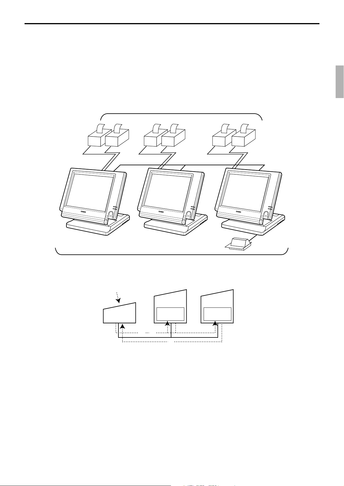
2-4. Check tracking system
2-4-1. Shared check tracking system
Up to 3 terminals can be included and check tracking can be performed for multiple
terminals connected to inline. This means that any terminal can be used to recall a
temporary closed check for additional registration or finalization.
System configuration
Up to 6 remote printers
OrderOrder
PRN (1) PRN (2)
4
1
Satellite
PRN (1) PRN (2)
CHK/BM
Up to 3 terminals
OrderOrder
Backup
master
Check
tracking
OrderOrder
PRN (1) PRN (2)
inline
CHK/M
Slip
Master
Check
tracking
Shared check tracking is performed as shown in the figure shown above.
1 A shared check operation (such as “new check” or “old check” etc.) is made at a
terminal.
2 The terminal sends the check number to the check tracking master and the backup
master. The master and backup master turn on the busy status.
3 The master sends back the check data (if the check number exists) or opens a new check
number.
4 A shared check transaction is finalized (by “new balance” or other finalize key).
5 The terminal sends the check data to the master and the backup master. And the master/
backup master clears the busy status of the check number.
QT-6100 Reference Manual
25
3
R-43
Page 44

Application System
2-4-2. Shared check tracking requirement
The following definition of memory allocation is required in each terminal before you can
perform shared check tracking.
• Number of check tracking tables:
For satellite, minimum one, for master, more than the number of estimated open checks
should be defined.
*
In case of using the next block **, one more check tracking table is consumed.
• Number of items/tables (per one item block
This is not the maximum number of items or functions but the number ordinarily
registered items or functions per one table. If the number of items or functions exceeds
this value during registration, the next block is used automatically for the following
transactions.
**
Number of item blocks:
Ordinarily, the registration requires one item blocks—but in a party for example—more
items are registered per one table. So it is necessary to define how many item blocks can
be used.
The maximum number of items or functions per one check is defined by the formula:
= (Number of items / tables) × (Number of item blocks (1 ~ 10))
When memory near end and memory end happens during registration, an error occurs.
See section A-5. Error messages of this manual.
*
**
):
2-4-3. Data backup when the master goes down
When the system has the backup master for the check tracking system, registered check
tracking data are stored both master and backup master automatically.
As soon as the system detects master down, the backup master roles as master for the check
tracking system.
(It is necessary to switch to backup master manually. See the “System down & Recovery”
chapter on page 9 of the installation & down recovery manual.)
When the system has no backup master for the check tracking system or both master and
backup master become down, no more check tracking operation and clerk interrupt
operation can be made.
R-44
Page 45

2-5. Other check tracking system control
2-5-1. The timing to clear check detail and index file after finalization
There are two timings to clear detail and index files.
1. The check is cleared after printing finalized data on slip or guest check receipt, or the
check is also cleared when the new or old check operation is made on the terminal
finalized the transaction.
2. The check is cleared after printing finalized data on slip or guest check receipt, or the
check is also cleared when the same finalized check number is assigned in new check
operation.
This option is set on the page 40 of the programming manual.
2-5-2. Table transfer
This function is used for transferring the contents of a check to another check.
The detail data can be excluded from the transferring check by programming (ST transfer).
There are two cases depends on the status of the transferring check.
1. If the transfer check is not used.
The entered check number is written.
2. The check number is already used.
Add the contents to the existing contents.
This option is set on the page 86 of the programming manual.
2-5-3. Store and recall
These functions are used for the driving through purchase.
The check number used in store operation is defined by check No. range programming.
2-5-3-1 Store
This function is used for storing the check No. of the registered items. The Detail / Index
at the drive-through entrance record the registered items and store it’s check No., and then
print out the temporary receipt. A customer receives this temporary receipt, and drives up
to the exit with this to receive the ordered item. The stored data transfer to the check
tracking master/backup master.
2-5-3-1 Recall
This function is used for recalling the transferred check No. to total the sum. The terminal
at the drive-through exit recalls transferring check No. in order of the oldest record. A
customer can receive the ordered items, and pay for them.
QT-6100 Reference Manual
R-45
Page 46
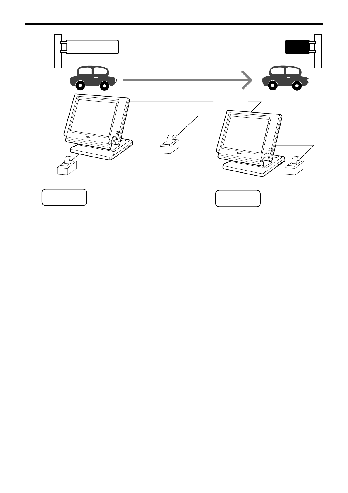
Application System
Entrance
Temporary receipt
R/J
Store
Press the <STORE> key →
Press the <STORE> key →
Hamburger
French Fries
Hot Coffee
CHK No.100
Cheese Burger
Orange Juice
CHK No.101
Order
PRN (2)
Order receipt
KITCHEN
Recall
Press the <RECALL> key →
Exit
Receipt
R/J
PRN (1)
CHK No.100
Hamburger
French Fries
Hot Coffee
Important
Press the <RECALL> key →
CHK No.101
Cheese Burger
Orange Juice
1. Without entering new check No., register items. After all ordered item have been
registered, press the <STORE> key at the entrance to summarize the registered items.
The check No. is issued automatically. The contents of these check No. transfer to the
check tracking master / backup Master.
2. Press the <RECALL> key to recall the check at the exit.
• A four-digit check No. should be used.
• When Open Check Z (All) report is printed out, the check No. range will be reset. After
this operation, the next check No. by using Store function will be the range start.
• This function works with the option “Clearing CHK/TBL No. by using the same number
again” to “Check number” only. (Refer to page 40 of the programming manual)
R-46
Page 47

2-6. Clerk control function
2-6-1. Clerk interrupt
The terminal can be programmed to allow the clerk interrupt function, which makes it
possible for multiple clerk to simultaneously use the same register. If a clerk starts
registration of a transaction, another can be interrupt the original registration and begin a
new one. The original clerk can later resume the interrupted original registration. You can
use the clerk interrupt function with the check tracking function.
Clerk 1 Clerk 2 Clerk 3
Registration
Registration
Registration
Finalization
Registration
Finalization
Guest
receipt issuance
Guest
receipt issuance
Registration
Registration
Finalization
Guest
receipt issuance
Sign on clerk 2 (clerk 1 registration put on hold)
Sign on clerk 3 (clerk 2 registration put on hold)
Sign on clerk 1.
Displays subtotal amount without add-on tax for clerk 1.
Sign on clerk 2.
Displays subtotal amount without add-on tax for clerk 2.
Sign on clerk 3.
Displays subtotal amount without add-on tax for clerk 3.
Sign on clerk 1
Sign on clerk 2
Sign on clerk 3
Notes
1) Error correct operation
The error correct operation cannot be performed for registrations made before a clerk
change. The error correct operation should be performed before clerk change.
2) Guest receipt
A guest receipt can be issued following clerk change, and receipts can be issued
separately for each clerk.
3) Cancel operation
The cancel operation can affect the entire transaction (multiple receipts: complete
cancellation) or only the same transaction (one receipt) by programming the <CANCEL> key.
QT-6100 Reference Manual
R-47
Page 48

Application System
2-6-2. Clerk detail memory
The terminal can summarize any daily / periodic total memory (such as fixed totalizer,
department, PLU, etc.) clerk by clerk.
After initialization, clerks have 10 detail memories which are assigned to gross, net, and
4 media in drawers. If you want to set more detail memories to clerks, allocate clerk detail
memory and detail link memory at the same time.
Clerk detail memory: File 011 / 111 / 211 / 311 / 411 / 511 / 611
Clerk detail link: File 030
2-6-3. Clerk training
Clerk training can be performed when employing new clerks or retraining clerks.
Training is normally performed during working hours, and the QT-6100 has the following
training functions.
1) It is not necessary to remove one terminal from the system for training purpose during
working hours.
2) Programming options, etc., are controlled exactly the same way as a working clerk.
3) Receipts are different from those normally used. The training receipts are filled with
training filler (“*” default.)
4) Only the REG/REF/REG– mode can be used for training.
2-6-4. Manager mode control
There is no actual REG 2 mode on the terminal, but you can control some functions (you
want) under manager control.
Preparation for this function:
1) Set “NO” to any functions you want to disable for CLERKS in the Allowed function 1
~ 5 list in the clerk programming. (See page 71 ~ 73 of the programming manual.)
2) Set the type of operator to “Manager” for the manager. (See page 64 of the programming
manual.)
Operation for this function:
REG C01 10-10-01 12:34 000001
1 PLU0001 •10.00
1 PLU0002 •20.00
1 PLU0003 •30.00
Operator mistake
3 •60.00
1. When the transaction is prohibited, the terminal displays
error message and the clerk calls the manager.
R-48
REG C01 10-10-01 12:34 000001
1 PLU0001 •10.00
1 PLU0002 •20.00
1 PLU0003 •30.00
Operator Code
---- 3 •60.00
2. The manager enters “2” and press the <REG MODE> key.
Page 49

REG C01 10-10-01 12:34 000001
1 PLU0001 •10.00
1 PLU0002 •20.00
1 PLU0003 •30.00
REG2 Mode
0.00
3 •60.00
REG C01 10-10-01 12:34 000001
1 PLU0001 •10.00
1 PLU0002 •20.00
PLU0003 -30.00
2 •30.00
REG C01 10-10-01 12:34 000001
1 PLU0001 •10.00
1 PLU0002 •20.00
REG Mode
3. The manager enters his/her secret code and press the <YES>
key. After this operation, the prohibited transaction can be
registered.
4. Perform manager operation (in this example; void operation).
0.00
2 •30.00
5. Pressing the <REG MODE> key is required, when the
manager returns his/her office.
QT-6100 Reference Manual
R-49
Page 50

Application System
2-7. Arrangement key function and scheduler
The arrangement key function provides a macro command function for the QT-6100
system. Any operation that can be performed using the keyboard of the QT-6100 can be
programmed to the arrangement file (file 038 ~ 438). Any operation programmed to the
arrangement file can be performed by pressing the arrangement key (function code 044).
Multi operations can be programmed into one arrangement program, and also entry of a
numeric parameter can be included anywhere in the arrangement program.
For example, when an arrangement program is programmed for executing fixed totalizer
Z consolidation for all terminal and the program is linked to an arrangement key, that
operation can be executed simply by pressing the arrangement key or attaching the iButton key to the receiver.
The scheduler function is provided for scheduled execution of arrangement key operation.
Execution of every specified time, as well as scheduled execution, can be performed using
this function.
The scheduler file (file 062) must be reserved to use the scheduler function.
2-7-1. Arrangement key function
The arrangement file and arrangement keys must be reserved for the QT-6100 to use the
arrangement key function.
The arrangement file is used to store the arrangement programs. An arrangement file
record is 24 bytes long, and a maximum of 9999 records can be reserved. Arrangement
programs are programmed using character data, and multiple arrangement programs can
be programmed in the arrangement file.
Multiple arrangement keys can be preset on the keyboard, and each key can be linked to
an arrangement program. The linked arrangement program is then called and executed by
pressing the arrangement key.
The following table shows the command parameters of the arrangement key function that
can be interpreted and executed by the QT-6100.
Command parameters can only be separated by spaces.
Note that spaces cannot be included within the command parameter.
Details of command parameters and their functions are explained next.
1) Number input
There are two methods to enter a number in an arrangement program.
– Constant number input
Preset a fixed number (constant value) enclosed in parentheses in the arrangement
program.
Example: To enter “1234” → preset (1234)
R-50
– Input of a single number when the arrangement program is executed.
A single number can be entered using the arrangement key. The number entered can be
used at any position and any time in the arrangement program.
Generally, an input number is temporarily stored in the work area (number entry buffer)
reserved for data processing, and is cleared after the processing is performed. With the
arrangement key function, a parameter save buffer is provided for saving the contents
of the number entry buffer. When a “%GET” command is encountered in an
arrangement program during processing, the data in the number entry buffer is saved
to the parameter save buffer. Set “%PUT” command to use the data saved in the
parameter buffer. The “%PUT” command can be used to load the data saved in the
parameter save buffer into the numeric entry buffer. These commands may be included
as often as necessary. The data in the parameter save buffer is changed only when a
“%GET” command is processed.
Page 51

Note:
• Set a “%GET” command, first, to use the number entered by the arrangement key later.
• When the “%GET” is programmed following constant number input, the constant
number is saved to the parameter save buffer.
• Numbers input using a “%PUT” command or by “([number])” are entered to the
number entry buffer in the same way as numbers input using the 10-key pad.
2) Key function specification
Any function key can be specified for an arrangement key function. :
[function code]:[record number] → Used for ordinary function keys
The numbers can be specified for zero suppression.
Note:
The arrangement key itself, cannot be programmed for in an arrangement program.
3) Mode setting
Any mode key can be specified for an arrangement key function. :
[function code]:[mode definition]→ Used for mode keys
Note:
121:01 : REG mode
121:02 : REF mode
121:03 :REG– mode
122:01 : X/Z mode:
122:02 : MGR mode:
122:03 : Collection/Consolidation mode:
122:04 : Auto-program mode:
122:05 : CF card:
123:01 : PGM1 mode:
123:02 : PGM2 mode:
123:03 : PGM3 mode:
123:04 : PGM4 mode:
123:05 : PGM5 mode:
123:06 : PGM6 mode:
4) Print control
There are two commands for controlling the printer:
PON : Output printout data.
POFF : Not output printout data.
QT-6100 Reference Manual
R-51
Page 52

Application System
5) Controlling the flow of arrangement command execution
There are 31 commands for controlling the flow of arrangement command execution:
:Snnnn : This is a start mark of an arrangement. “nnnn” (4-digits code) are used for
(nnnn) : “nnnn (no digit limitation)” means numeric entry.
NN:nnnn : “NN” is a function code which is executed in this arrangement, “nnnn” is the
:[label] : Preset the label (name of specific position) to specify the jump destination
Example: To specify “LABEL-1” as label → :LABEL-1
G:[label] : This is an absolute jump command. If the system encounters this command,
arrangement table number set to each arrangement key.
record No. of the function.
point in the arrangement file. The actual data for labels can be freely
designated.
command execution flow unconditionally jumps and continues from the
point preset by the label.
I > ([number]):[label] : This is a conditional jump command. If the system
encounters this commands, the value in the number
entry buffer is compared with the specific number. If the
value in the buffer is larger than the specified number,
the command execution flow jumps and continues from
the point preset by the label. If the condition is not match
with the above-mentioned condition, the step advances
to the next command.
I < ([number]):[label] : This is a conditional jump command. If the value in the
number entry buffer is less than the specified number,
the command execution flow jumps to the point preset
by the label. If the condition is not match with the abovementioned condition, the step advances to the next
command.
I – ([number]):[label] : This is a conditional jump command. If the system
encounters this command, the value in the numeric
entry buffer is compared with the specific number. If the
value in the buffer is equal to the specific number, the
command execution flow jumps and continues from the
point preset by the label. If the condition is not match
with the above-mentioned condition, the step advances
the next command.
R-52
KNO1 : This is a command to enter the <#-1> key.
KNO2 : This is a command to enter the <#-2> key.
NE : This is a command to wait for numeric entry. After entering numerics,
press the <ARRANGEMENT> key to continue the arrangement
program.
Page 53

? : Force to execute the arrangement even if an error occurred during the
arrangement.
ANO : Disable clerk auto sign-off.
AYES : Enable clerk auto sign-off.
CFFMT :Format CF card.
CFSVnnn’mmmm’ : Backup to CF card (nnn: command code, mmmm: file name).
CFLDnnn’mmmm’ :Restore from CF card (nnn: command code, mmmm: file name).
JCL : Clear electronic journal older half data
JCLA
CLPn : Set the default @ menu sheet number to “n” (n = 0 ~ 2) and “stay down
CLMn : Set the default menu sheet number to “n” (n = 0 ~ 15) and “stay down
CLSn : Set the default shift PLU level number to “n” (n = 0 ~ 8).
211: : Press the “ESC” key.
212: : Press the “YES” key.
213: : Press the “NO” key.
: Clear all electronic journal data
@ menu sheet assignment” of all clerk.
menu sheet assignment” of all clerk.
%GET : Read from key buffer.
%PUT : Write to key buffer.
CLL0n : Set the default clerk pop-up window number to “n” (n = 0 ~ 9).
!:sss : Wait the next step for “sss” (ss = 001 ~ 327) sec.
F:m:nn : Sending data (designated by “nn”) to the terminal (designated by “m”)
via FTP.
“m” means the rec-# of file-912, “nn” means the rec-# of file-913
6) End of the arrangement programs
The end command “E” must be included at the end (exit) point of an arrangement program.
QT-6100 Reference Manual
R-53
Page 54

Application System
2-7-2. Arrangement program example
This section shows examples of arrangement programs.
The following example shows an arrangement program that executes X consolidation of
the file set in the batch 1 ~ 9 files for all terminals.
Example:
Programming the following operation for the arrangement table 12
– Set the mode to Inline X/Z.
– Enter operation code “1111100000000”.
– Wait for the numeric entries (batch number).
– Enter the <#-2> key.
– Enter the <ESC> key.
:S0012 ; Designate the table number (mandatory)
122:03 ;Set the mode to Inline X/Z.
NE ;Wait for the batch number
I<(0):ERR1 ;If the input number is less than 1, the process jumps to the ERR1.
I>(9):ERR1 ;If the input number is larger than 10, the process jumps to the ERR1.
%GET ;Save the entered number to the parameter save area.
202:0031 ;Press “Clear” button.
(1111100000000) ;Input the operation code for system command
%PUT ;Pick up the entered number from the parameter save area.
KNO2 ; Specify the <#-2> key for entering the operation code.
211:0045 ;Specify the <ESC> key to execute this operation.
:ERR1 ; When the input number is not 1 to 9, the following commands are
processed.
E ; End the program (mandatory).
2-7-3. Scheduled execution of arrangement key function
An arrangement key function can be executed on a scheduled basis. In order to execute an
arrangement key function on a scheduled basis, it is necessary to make appropriate settings
in the scheduler file (file 062).
There are two functions for execution on a scheduled basis:
1) Execute an arrangement key function at the specified time.
2) Interval execution of an arrangement key function by setting start time, ending time,
and the interval.
See the page 42 of the programming manual for programming details.
R-54
Page 55

2-8. Making graphic logo
A graphic logo can be printed on internal receipt or UP-360 receipt. This graphic logo is
stored in the graphic logo file ( file 047 for UP-360), and printed at the top of the receipt
instead of a normal logo message.
This graphic logo data cannot be made by the terminal program, it can be made only by PC
and downloaded from PC.
2-8-1. About graphic logo
Graphic logo size: 432 × 104 or 432 × 208 pixels
Printing sample:
**************************************
* QT-6100 TERMINAL *
* GRAPHIC LOGO AREA *
**************************************
*******COMMERCIAL MESSAGE LINE 1*******
*******COMMERCIAL MESSAGE LINE 2*******
*******COMMERCIAL MESSAGE LINE 3*******
*******COMMERCIAL MESSAGE LINE 4*******
2-8-2. Making graphic logo procedure
Before following this procedure please allocate “Graphic logo” file (file 047) on the terminal.
1. Making a bit-map image file:
(432 × 104 or 432 × 208 pixels; 1-bit color for UP-360).
2. Convert this bit-map file to the internal file by executing such PC software as CV.
PC sends the converted data to the terminal via online automatically.
3. Select “Print Graphic” option in the message control of the general feature in the PGM
3 mode.
4. Turn off and on the terminal by the <DISP ON/OFF> button.
QT-6100 Reference Manual
R-55
Page 56

Application System
2-9. Hourly item
This function enables to memorize the detailed data of quantity and amount / price of each
item dealt hourly.
It is possible to calculate the proceeds and record the hourly item in any totalizer, and also
it is possible to print out as an hourly item report.
2-9-1. Programming necessary files before using hourly item function.
Hourly item function requires the following files to function properly, so they must be
programmed before using it. See the programming manual for the details on format of
individual files.
– Time zone file
This file is used to specify the time zone for the detail items individually. You can enter
the starting time and the ending time of the time zone, moreover specify the cycle time that
indicates an unit of the appropriate intervals.
– Hourly item link file
This file is used to record the Hourly item which links with the appropriate time zone. You
can also specify the particular totalizer for each time zone.
– Hourly item
This file is used to store the contents of the quantity and amount of each registered item.
The following seven files enable to link the data for hourly item link file: fixed totalizer,
function, subdepartment, PLU, department, group, void reason.
Hourly item report example
08:00->09:00
Hamburger 2 $2.00
French Fries 3 $1.50
--------------------------------------- $3.50
09:00->10:00
Cheese Burger 2 $3.00
Hot Coffee 2 $0.50
--------------------------------------- $3.50
:
13:00->13:15
Apple Pie 1 $1.00
Hot Milk 1 $1.00
----------------------------------------
Time zone file
Start End Cycle
Time Time
Zone
08:00 12:00 01:00
13:00 14:00 00:15
• • •
• • •
• • •
Hourly item link
REC No. File No.
20 items
20 items
0001 004
0011 001
• •
• •
• •
• •
• •
0005 012
0008 012
• •
• •
• •
• •
A maximum of 20 records
corresponds to each time
zone.
R-56
Page 57

2-10. Time and attendance
This function allows shop owners to control his / her employees’ working condition. Time
& attendance require the following files.
– Employee file
This file is used to regulate the labor conditions.
You can program the type of job, the maximum work hours in a week or shift schedule
of a day per employee.
– Job code file
This file is used to classify the types of job. You can program the general work pay and
the overtime pay ratio per job file.
If some employees have a common job, you can divide the job code individually in case
their pay ratio is different.
– Schedule file
This file is used to administrate the employees’ schedule. You can assign a starting and
an ending time, a grace period, break minutes allowed, and the default job code for the
shift. It is possible to record maximum 21 shifts (3 shifts × 7 days) per employee for the
schedule file.
Grace period – this is a period of time in minutes which allows an employee to clock-in /
out before / after their scheduled times. Grace period works in conjunction with the
schedule. If the scheduler is not being utilized then the grace period inputs indicated
below become inactive.
Mon
day
Tuesday
•
•
•
•
Sunday
Shift
Shift
Shift
Shift
Shift
Shift
Grace period before start time – this input indicates how many minutes an employee may
clock-in before the scheduled clock-in time.
Grace period after start time – this input indicates how many minutes an employee may
clock-in after the scheduled clock-in time.
Grace period before end time – this input indicates how many minutes an employee may
clock-out before the scheduled clock-out time.
Grace period after end time – this input indicates how many minutes an employee may
clock-out after the scheduled clock-out time.
(See “4-1-15. Programming time & attendance” for the programming manual.)
Job
Code
1
5
2
3
2
4
•
•
•
•
Start
Time
9:00
13:00
16:00
9:00
13:00
16:00
•
•
•
•
End
Time
12:00
15:00
18:00
12:00
15:00
18:00
•
•
•
•
Break
Time
00:15
00:15
00:15
00:15
00:15
00:15
•
•
•
•
Grace Before
Start
10
10
10
10
10
10
•
•
•
•
Grace After
Start
10
10
10
10
10
10
•
•
•
•
Grace Before
End
5
5
5
5
5
5
•
•
•
•
Grace After
End
15
15
15
15
15
15
•
•
•
•
Each employee can have 3 shifts per day. The schedule file can hold 7 days schedule.
So, totally 21 files can be registered in this file.
QT-6100 Reference Manual
R-57
Page 58
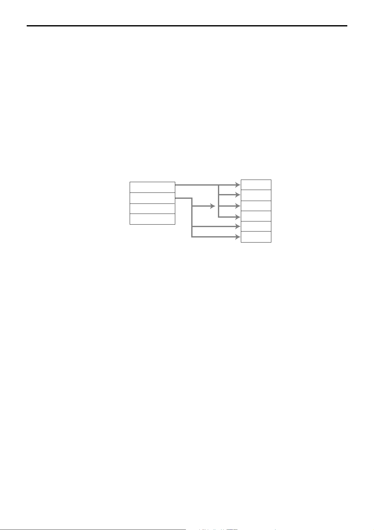
Application System
Job 1
Job 2
Job 3
Job 4
Job 5
Job 6
Employee 1
Employee 2
Employee 3
Employee 4
Job code
– Work time file
This file is used to administrate each employees’ weekly hourly wages, work hours, and
proceeds.
– Time zone file
This file is used to administrate the cycle time. You can specify the length of time zone.
2-10-1. Corresponding relations of the file
Employee's job assign
This function is used to assign a job to each employee. Before assigning the job, be sure
to program the details of the jobs. Every employee file can link to some job code files
(maximum 4 jobs), so some employees may link to the same job code file. But be sure to
make individual job files if the employees work under different hourly wages.
R-58
Page 59

Employee’s Schedule and total business results per week
Schedule
Employee 1
Employee 2
Employee 3
Employee 4
Work time
Employee 1
Employee 1
Employee 1
Employee 1
Employee 1
Employee 1
Employee 1
Employee 1
Employee 1
First week
First week
First week
First week
•
•
•
First week
Second week
Second week
Second week
•
•
•
Second week
Monday
Monday
Monday
Tuesday
Sunday
Monday
Monday
Monday
Sunday
Shift 1
Shift 2
Shift 3
Shift 1
Shift 3
Shift 1
Shift 2
Shift 3
Shift 3
Employee 1
Employee 1
Employee 1
Employee 1
Employee 1
Employee 2
Employee 2
Employee 2
Monday
Monday
Monday
Tuesday
•
•
•
Sunday
Monday
Monday
Monday
•
•
•
Shift 1
Shift 2
Shift 3
Shift 1
Shift 3
Shift 1
Shift 2
Shift 3
Employee 2
Employee 2
Employee 2
Employee 2
Employee 2
Employee 2
Employee 2
Employee 2
First week
First week
First week
First week
•
•
•
First week
Second week
Second week
Second week
Monday
Monday
Monday
Tuesday
Sunday
Monday
Monday
Monday
Shift 1
Shift 2
Shift 3
Shift 1
Shift 3
Shift 1
Shift 2
Shift 3
QT-6100 Reference Manual
R-59
Page 60

Application System
Calculating the total wages of the employees per hour
Time zone
Zone 1 Cycle 1
Zone 1 Cycle 2
Zone 1 Cycle 3
Zone 2 Cycle 1
Zone 2 Cycle 2
Flow of Time & Attendance operation
The following flow shows the order of time & Attendance function by pressing the
specified keys: It is possible to specify one key as both <CLOCK-IN> and <CLOCKOUT> function, or specify two keys separately. ( Refer to “4-3-7-33 Worksheet for clockin/clock-out” in the programming manual for details.)
CLOCK-IN →
BREAK-IN → BREAK-OUT
(
Hourly/Labor
Totalizer 1
Totalizer 2
Totalizer 3
Totalizer 4
Totalizer 5
→ CLOCK-OUT
)
2-10-2. Clock-in operation
This function is used to register the Starting work time.
2-10-2-1. Clock-in operation (1)
Program: Not using the window and impossible to specify job code.
Allow to specify job code = NO, Display job code window = NO
(Refer to the page 54 of the programming manual.)
Operation
REG 10-10-01 11:59 AM 001234
GLENN DEAL 11:59 AM
Clock-in OK?
0.00
1. XXXXXX <CLOCK-IN>
When this message appears, press the <YES> key to register
the start of working hours.
R-60
XXXXXX
Employee No.
Page 61

2-10-2-2. Clock-in operation (2)
Program type:
Allow to specify job code = YES, Display job code window = NO
(Refer to the page 54 of the programming manual.)
Operation
REG 10-10-01 11:59 AM 001234
GLENN DEAL 11:59 AM
Clock-in OK?
0.00
2-10-2-3. Clock-in operation (3)
Program type:
Display job code window = YES
Allow to clock-in with non-preset job-code = NO
(Refer to the page 54 of the programming manual.)
Operation
REG 10-10-01 11:59 AM 001234
CLOCK-IN
1.Cashier
2.Cook
3.Dish Washer
4.Cleaning
0.00
1. XXXXXX . YY <CLOCK-IN>
When this message appears, press the <YES> key to register
the start of working hours.
Enter the employee No. (within 6 digits), “.”(decimal point),
and the job code (2 digits).
XXXXXX . YY
Employee No. Job code
1. XXXXXX <CLOCK-IN>
2. Choose the appropriate Job Code from the CLOCK-IN menu,
and press the <YES> key to register the start of working
hours.
→ Job codes that are programmed in Employee file are displayed.
XXXXXX
Employee No.
QT-6100 Reference Manual
R-61
Page 62
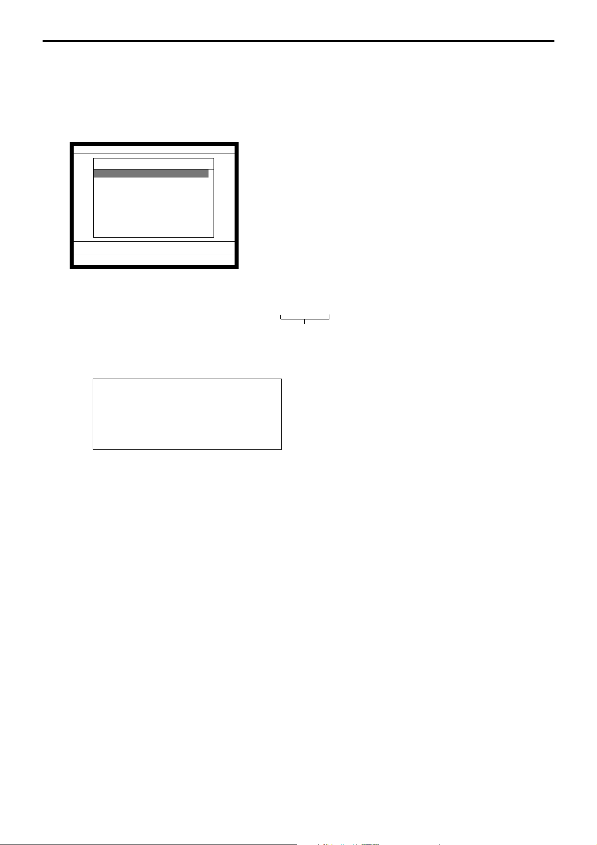
Application System
2-10-2-4. Clock-in operation (4)
Program type: Display job code window = YES
Allow to clock-in with non-preset job code = YES
(Refer to the page 54 of the programming manual.)
Operation
REG 10-10-01 11:59 AM 001234
CLOCK-IN
1.Cashier
2.Cook
3.Dish Washer
4.Cleaning
5.JOB A
6.JOB B
7.JOB C
8.JOB D
0.00
1. XXXXXX <CLOCK-IN>
2. Choose the appropriate Job Code from the CLOCK-IN menu,
and press the <YES> key to register the start of working
hours.
→ All job codes that are programmed in job code file are displayed.
XXXXXX
Employee No.
Receipt sample
MC #01
REG C01 12-31-2005 11:59 AM 001234
Harrison
CLOCK-IN 11:59 AM
JOB Dish Washier
If you want to change these special characters, refer to the page 112 of the programming
manual.
— Header
— Employee character (16 digits)
— Special character (REC #29), time
— Special character (REC #33), job character
R-62
Page 63
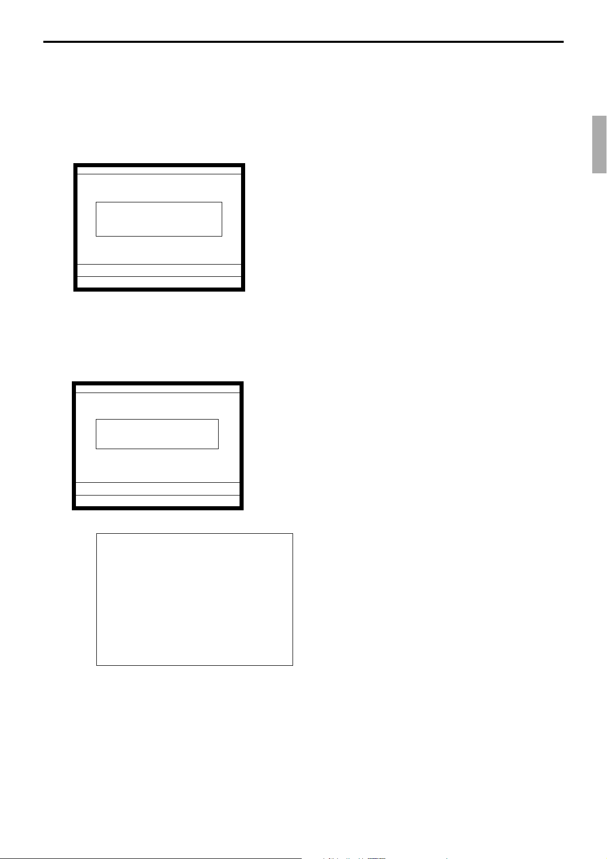
2-10-3. Clock-out operation
This function is used to register the ending work time.
2-10-3-1. Clock-out operation (1)
Operation
REG 10-10-01 11:59 AM 001234
GLENN DEAL 11:59 AM
Clock-out OK?
0.00
2-10-3-2. Clock-out operation (2)
Program: Tip declaration compulsory (refer to the page 53 of the programming manual.)
Operation
REG 10-10-01 11:59 AM 001234
Enter cash tip amount and
press <YES> key.
0.00
Receipt sample
MC #01
REG C01 12-31-2005 11:59 AM 001234
1. XXXXXX <CLOCK-OUT>.
2. When this message appears, press the <YES> key to register
the end of working hours.
1. XXXXXX <CLOCK-OUT>.
2. When this message appears, the employee should enter the
cash tip amount, if not, it is impossible to close the accounts
— Header
Harrison
CLOCK-IN 11:59 AM
JOB Dish Washier
CLOCK-OUT 01:59 PM
WORK TIME 02:45
BREAK TIME 00:45
CASH TIP $12.34
If you want to change these special characters, refer to the page 112 of the programming
manual.
QT-6100 Reference Manual
— Employee character (16 digits)
— Special character (REC #29), time
— Special character (REC #33), job character
— Special character (REC #30), time
— Special character (REC #34), working hours
— Special character (REC #35), recess
— Special character (REC #36), cash tip amount
R-63
Page 64

Application System
2-10-3-3. Break-in operation
This function is used for the employees to register a recess.
Operation
REG 10-10-01 11:59 AM 001234
GLENN DEAL 11:59 AM
Break-in OK?
0.00
2-10-3-4. Break-out operation
This function is used for the employees to register the end of a recess.
1. XXXXXX <BREAK-IN>.
2. When this message appears, press the <YES> key to register
the start of a recess.
The receipt is not printed out, except electronic journal.
Operation
REG 10-10-01 11:59 AM 001234
GLENN DEAL 11:59 AM
Break-out OK?
0.00
2-10-3-5. Manager operation
When the manager operate CLOCK-IN after signing on, the manager can operate and
modify any employee’s record despite of corresponding employee number.
Following operations are possible to operate by the manager:
1. XXXXXX <BREAK-OUT>.
2. When this message appears, press the <YES> key to register
the end of a recess.
The receipt is not printed out, except electronic journal.
R-64
Operating Flow
Manager sign on
Specify the job code / CLOCK-IN / CLOCK-OUT / BREAK-IN / BREAK-OUT
→→
→ CLOCK-IN/OUT operation, BREAK-IN/OUT operation
→→
→→
→ Sign off
→→
Page 65

2-11. Sign on control
This function is used to prohibit the sign-on operation by an employee who has not
CLOCK-IN. The following conditions should be fixed.
• Use only one terminal (master terminal) for the CLOCK-IN/OUT operation. This
terminal should be connected inline to the satellite terminals. But the time and
attendance work file (file 806) should be allocated to all terminals.
• The clerk file’s information should be common among all the terminals.
• Be sure there is a clerk who is specified as “Manager” in the clerk file. If no manager,
it may be locked to operate.
2-11-1. Sign on
1. When an employee normally operate CLOCK-IN/OUT, BREAK-IN/OUT, the
employee’s attendance information is sent from the main terminal to the satellite
terminals.
CLK# information
CLK#1 information
CLK#2 information
CLK#3 information
•
•
CLK#99 information
Flow of sign on
Sign on by
Manager
Sign on by
Clerk
Sign on OK
CLOCK-IN
CLOCK-IN unfinished
He/she is NOT in the
middle of BREAK-IN
He/she is in the
middle of BREAK-IN
Unable to Sign on
(E175 Error message appears)
Sign on OK
Unable to Sign on
(E175 Error message appears)
QT-6100 Reference Manual
R-65
Page 66

Application System
2-11-2. Solution to abnormality of master terminal
When the satellite terminals cannot receive any information from the master terminal, the
master terminal shows the error message on the window and prints out the receipt with
terminal IDs that failed to communicate the data.
REG 10-10-01 11:59 AM 001234
Harrison
CLOCK-IN 11:59 AM
JOB Dish Washier
E177 Time&Attendance Data
Communication Error.
Please Call Manager.
0.00
Please sign on.
Receipt image
MC #01
REG C01 12-31-2005 11:59 AM 001234
Communication Error
MC#01 XXXX
MC#03 XXXX
— Header
— Fixed message
— Machine ID, Error code
— Machine ID, Error code
• The error message and receipt will appear whenever the sign-on is failed. If you cannot
solve the inline data communication problem, program the system connection again,
and remove the uncommunicative terminal.
2-11-3. Solution to abnormality of satellite terminal
• When the satellite terminal cannot receive any information from the master terminal,
the default CLOCK-IN/OUT information remain.
In this case, only manager can sign on.
• When the satellite terminal could receive the CLOCK-IN/OUT information from the
master terminal only once, but failed to receive after then, the CLOCK-IN/OUT
information in each satellite terminal has left in the last received condition. In such case,
the last received information control employees’ sign on/off. (Manager can always sign
on.)
2-11-4. Sign on compulsory
R-66
When the satellite terminal cannot receive the information in spite of normal CLOCK-IN
operation on the master terminal, an employee may not sign on for some reason.
In such case, the manager needs the following operation.
1. Sign on by the manager (normal sign on operation.)
2. 99 xxxx <CLK#> (xxxx: the secret code of the corresponding employee, 4-digit.)
3. Sign off by the manager and the corresponding employee can sign on.
Note:
When the error message appeared under the employee’s CLOCK-IN operation, manager
should operate above steps.
Page 67

2-12. IDC (Item Data Capture)
This function is used for capturing all the registered item data by the REG / REF / REG–
modes. IDC file stores these captured items. If there is no record to capture item data, the
new data are not captured to the IDC file.
2-12-1. Available capturing items
Select the appropriate items that should be captured, and program these items into the IDC
link file. The available items and their contents are indicated below.
Items Contents File No.
PLU
Subdepartment
Department
Function
Pulldown group
Clerk
• The index of the transaction.
• The report of the items/functions, or all the
detailed statements.
• The index of the transaction.
• The report of all the detailed statements.
004
003
005
002
026
007
QT-6100 Reference Manual
R-67
Page 68

Application System
IDC function file
Function Code
NOP 000 –
●
Cash amount tendered
● Charge 002
● Check 003
● Credit 004
●
Food stamp tender
● New balance *12 006
● EBT tender 007
Price inquiry 008
Stock inquiry 009
● Text recall *11 010
● Text print *11 011
Check print 012
Clerk transfer 013
● Table transfer *10 014
● Tip 015
Normal receipt 016
● Loan 019
●
Received on account
● Paid out 021
● Pick up 022
● Coupon 023
● Deposit 025
● Minus 027
● Discount 028
● Plus 029
● Premium 030
Refund *1 033
●
Error correct/Void
Coupon 2 *1 036
Validation 037
Receipt 038
Check endorsement
● Non-add *11 040
● Non-add/No sale *4/11 041
No sale 042
No. of customer *5 043
Arrangement *6 044
Currency exchange
VAT 046
Bill 047
PLU *7 048
001
005
020
*3 034
039
*1 045
Function Code
Price 049
O
● Department 051
O
O
O
O
O
O
–
–
O
O
–
–
O
O
O
O
O
O
O
O
O
O
O
O
O
O
O
O
–
–
–
O
O
–
O
O
O
–
–
–
Slip back feed/Release
Slip 055
Slip feed/Release 056
Tax status shift *1 057
Table number *5 058
Food stamp shift *1 059
Declaration 061
● Tax exempt 062
● Flat PLU 063
Menu shift 064
Shift PLU *1 065
Open 067
Open 2 068
First unit price *1 069
Second unit price *7 070
Clerk number *5 072
Operator read/reset
● Tray total *13 074
● Subtotal *8 075
Receipt On/Off 076
Taxable amount subtotal
Operator number 078
Merchandise subtotal
Food stamp subtotal
Multiplication *1 082
Quantity/For *1 083
Square *1 084
Selective item subtotal
Cube *1 090
New check 091
Old check 092
New/Old check 093
Add check *9 094
Separate check *9 095
Two zero (00) 096
Three zero (000) 097
Decimal point 098
OBR *7 103
Clock-in/out 108
Break-in/out 109
Coupon number 110
054
073
077
*8 080
081
*2 085
Function Code
–
O
–
–
–
O
O
O
–
O
O
–
O
–
–
O
O
O
–
O
O
–
–
–
O
–
O
O
O
O
O
–
–
–
–
–
–
–
–
–
–
–
–
Substitution 111
Ketten Bon *1 113
House Bon *1 114
Post entry 115
Round repeat 116
Open check 117
● Media change 118
Seat number 119
Display On/Off 120
Mode 124
● Eat-in 128
● Takeout 129
● Store 130
Recall 131
● Subdepartment 133
Subdepartment number
Department number
List *7 136
List number *7 137
Dutch account 140
Customer No. *5 148
Payment *5 149
Numerics (0 ~ 9) 201
Clear 202
Reverse display 206
Electronic journal display
Escape 211
Yes 212
No 213
Left arrow (←) 214
Right arrow (→) 215
Up arrow (↑) 216
Down arrow (↓) 217
Home 218
Display mode 219
Page down 220
Page up 221
● Cancel 236
Item search 248
Order character change
Location change 260
Table sharing 261
*7 134
*7 135
207
252
–
O
O
–
–
–
O
–
–
–
O
O
O
–
O
–
–
–
–
–
O
O
–
–
–
–
–
–
–
–
–
–
–
–
–
–
–
O
–
–
–
–
● : Available items to be programmed as target for IDC.
O
: IDC target
– : Out of target
R-68
Page 69

*1 This function itself is not captured. But it is captured with the captured items or
functions.
*2 Selective item subtotal is captured with selective item discount or premium.
*3 1. Error correct is not captured.
2.
This function itself is not captured. But it is captured with voided items.
3. Void reason is also captured.
*4 No sale is not captured.
*5 These functions (items) are captured in header record.
*6 This function itself is not captured. But the functions that are executed by this
function are captured.
*7 This function is not captured. But item itself might be an IDC target.
*8 When the option (printed when the key is pressed) is selected, it is captured.
*9 Transferred items by the add check and the separate check are not captured.
*10 ST transfer is not captured.
*11 This function is captured only in the sales registration.
*12 This function is captured only in the check tracking registration.
During clerk interrupt operation, this is not captured.
*13 Tray total is captured when it is pressed twice.
QT-6100 Reference Manual
R-69
Page 70

Application System
2-12-2. Set up the IDC start / end
Specify IDC Start or IDC End in manager mode. IDC does not start if you not allocate
necessary files for IDC.
• When IDC function is stopped, you can restart IDC by performing FC or INIT 2
(Refer to the page 10 of the programming manual.)
Operation
Item Data Capture
Item Data Capture YES
0.00
Note:
1. If you stop the IDC when the IDC file is full of items, you can stop the error alarm
without clearing any registered data.
2. The necessary files for IDC
• File 036 (Registration buffer)
• File 063 (IDC buffer)
• File 057~ 059 (IDC file)
• File 804 (IDC link file)
R-70
Page 71
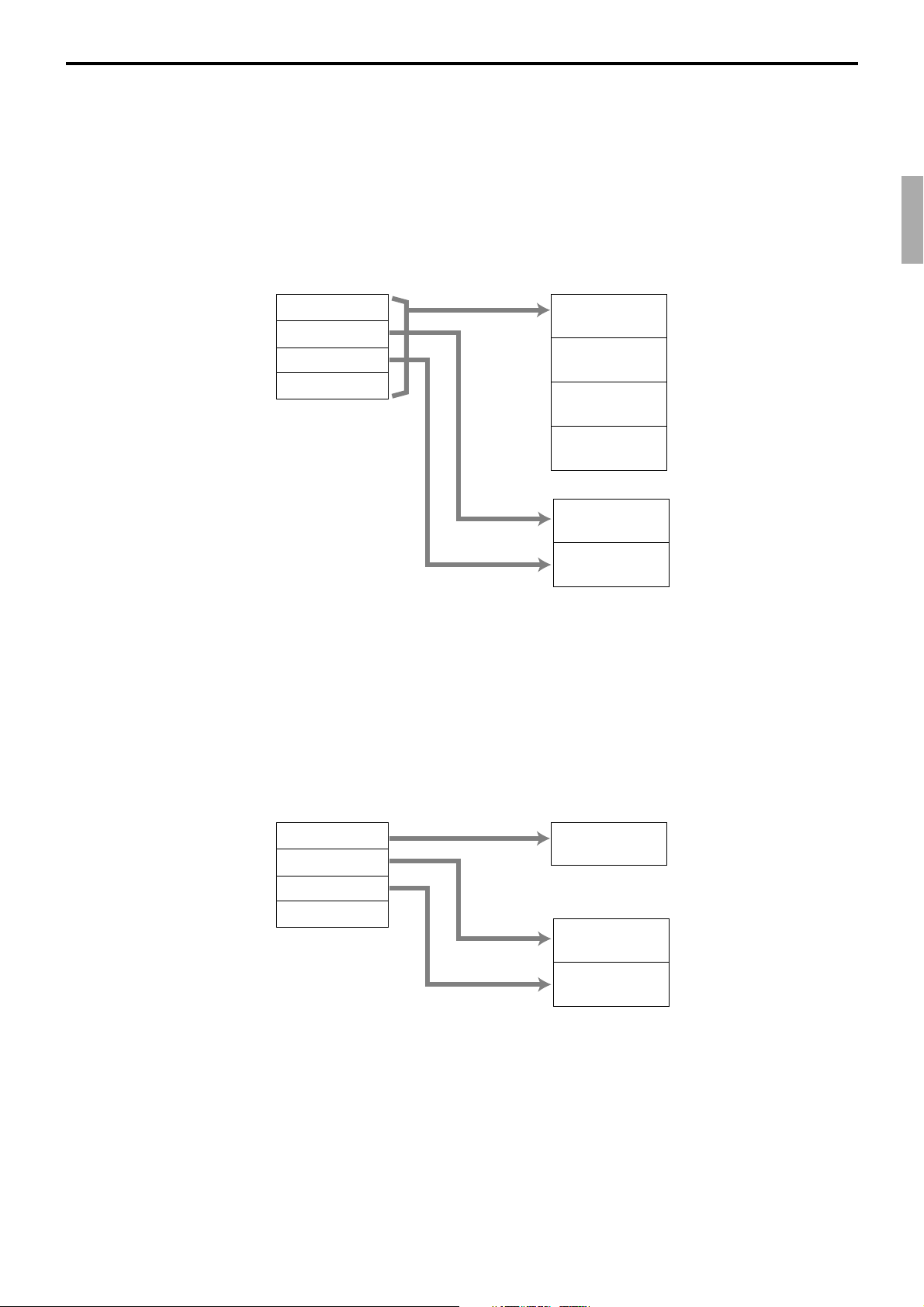
2-12-3. How to memorize the captured items
Header
PLU 0001
Header
PLU 0002
Header
PLU 0003
Header
Total
PLU 0001
PLU 0002
PLU 0003
Total
IDC Buffer
IDC file (1)
Header
PLU 0002
Header
PLU 0003
IDC file (2)
Header
PLU 0001
PLU 0001
PLU 0002
PLU 0003
Total
IDC Buffer
IDC file (1)
Header
PLU 0002
Header
PLU 0003
IDC file (2)
Flow of the transferring data
1. Program: “Store data = Whole transaction” (refer to the page 56 of the programming
manual.)
Example
PLU 0001———> Memorized all the transaction into the IDC file (1)
PLU 0002———> Memorized into IDC file (2)
PLU 0003———> Memorized into IDC file (2)
QT-6100 Reference Manual
2. Program: “Store data = Item only” (refer to the page 56 of the programming manual.)
When an appropriate item is selected, this item and the header will be captured (see the
illustration below).
Example
PLU 0001———> Memorized into IDC file (1)
PLU 0002———> Memorized into IDC file (2)
PLU 0003———> Memorized into IDC file (2)
R-71
Page 72

Application System
0 12 24
Allocated record number Used record number
50
0811 13 16 19 21
Customer-#
Payment
1
01
26
Consecutive
No.
Mc ID
Mode
Clerk-#
Check-#
Time
Number of
purchsed item
Not Used
31 36 41 4847 502
Net total
Subtotal
without tax
Subtotal
with tax
Date
Mode
D4:
01 = REG, 02 = REF, 03 = REG–
D3:
D2:
00 = Normal, 01 = Training
D1:
Clerk-#
D6:
Clerk #; newly created this check
D5:
D4:
Clerk #; last opened this check
D3:
D2:
Clerk #; opening this check
D1:
Payment
D2:
00: Non-payment, 01: Payment
D1:
File-# *1
Gross
quantity
05712 17 50
Type *2
1
03
Gross
amount
Mc ID
Not Used
Rec-# *1
32
2-12-4. IDC data file structure
Top record (Top record of each IDC file)
Header
Item
Item (PLU / Subdepartment / Department)
035 911 13 18 23
1
03
Mc ID
Type *2
72
Rec-# *1
File-# *1
Void reason
Item status *4
Tax status *3
Quantity
Amount
28
30 32 35
Unit price
Pulldown group
rec-#
Function
Cash, Charge, Check, Credit
03 79 14 19 24 29 30
1
Mc ID
2
03
Type
File-# *1
5
Rec-#
CE key
Rec-# *1
foreign
currency
amount in
Tendering
local
currency
Tendering
amount in
Amount
Change
Total Amount
Totaling Type
Food stamp tender, EBT tender
03 7 12 17 22 2728
1
Mc ID
Totaling Type
5
2
03
Type
File-# *1
Rec-# *1
Tendering
amount
amount
subtotal
Food stamp
Food stamp
change amount
(only for FS/TD)
Amount
Cash change
Totaling Type
0: Total operation, 1: Change operation, 2: Partial tender operation
code
Random
Not Used
50
Not Used
50
Not Used
50
Not Used
R-72
*1 ~ *4: Refer to the last page of this section.
New balance
Page 73

New balance fee
File-# *1
New balance
fee
057
12 50
Type *2
1
03
Mc ID
Not Used
Rec-# *1
32
Cashing a check
057 14 24 2919 50
1
32
03
Mc ID
Type *2
File-# *1
Rec-# *1
Not Used
Amount
tendered
Cashing
a check fee
Change
amount
Not Used
Text print, Text recall
035 47
1
2
03
Mc ID
Type *2
7
Rec-# *1
File-# *1
Character
50
Not Used
05712 5013
03
Mc ID
Type *2
05712 5013
2
03
Mc ID
Type *2
05712 5013
2
03
Mc ID
Type *2
Rec-# *1
File-# *1
Rec-# *1
File-# *1
Rec-# *1
File-# *1
Table transfer
ST
Tip
Amount
Loan / Pickup
Amount
18 242
check-#
Original
New
check-#
Not used
Not used
Not used
05712 5013
2
03
Mc ID
*1 ~ *4: Refer to the last page of this section.
QT-6100 Reference Manual
Received on account / Paid out / Deposit
Type *2
Rec-# *1
File-# *1
Amount
Not used
R-73
Page 74
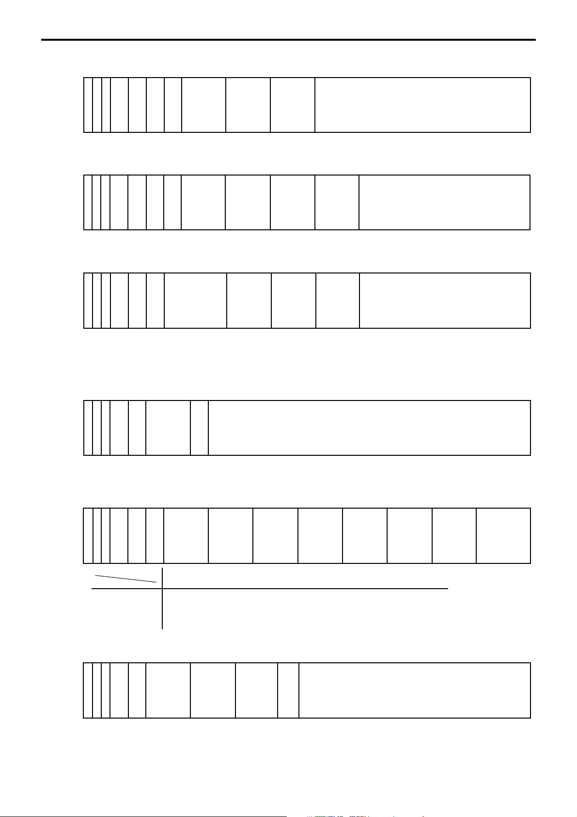
Application System
+ / - / Coupon
0
35 911 16 211 50267
2
03
Mc ID
Type *2
25 91 507
3
0
03
Mc ID
Type *2
0
25 9 16 21 261 507
03
Mc ID
Type *2
05712 5013
Rec-# *1
File-# *1
Tax status *3
Item status *4
%+ / %-
Rec-# *1
File-# *1
Tax status *3
Item status *4
%+ / %- after selective item subtotal
FIile-# *1
Selective item
Selective item status-#
1: Selective item 1
2: Selective item 2
status-#
Rec-# *1
# print (# or #/NS)
No.
11 16 21 26 31
No.
Not Used
142
Amount
Amount
Amount
Price
Price
Rate
Rate
313
amount
Discount
Not Used
Not Used
Not Used
03
Mc ID
Type *2
File-# *1
Rec-# *1
Number
Figures
Not used
Tax exempt
0
35 9 14 19 24 291 50347
03
Mc ID
Type *2
Field name Taxable Taxable Taxable Taxable Taxable Taxable Taxable
Tax system amount 1 amount 2 amount 3 amount 4 amount 5 amount 6 amount 7
Canada TA1 TA2 TA1 & 2 TA3 TA1 & 3 TA4 TA1 & 4
Singapore TA1 TA1 & 3 TA2 TA 2 & 3 TA3 -- --
Rec-# *1
File-# *1
VAT TA1 TA2 TA3 TA4 TA5 TA6 TA7
U.S. TA1 TA2 TA3 -- -- -- --
Tax status *3
Taxble
amount 1
Taxable
amount 2
Taxable
amount 3
Taxable
amount 4
Taxable
amount 5
ST / MDST
03
Mc ID
51217
2
03
Type *2
File-# *1
Subtotal
Rec-# *1
amount
Printed
amount
subtotal
22
amount
Subtotal
after CE
241 507
rec-#
CE key
392
Taxable
amount 6
Not Used
44
TAxable
amount 7
Not Used
R-74
*1 ~ *4: Refer to the last page of this section.
Page 75

057 5013
2
03
Mc ID
Type *2
05712 5013
03
Mc ID
Type *2
05712 50132
03
MC ID
Type *2
Media change / Tray total
Rec-# *1
File-# *1
Store
amount
Subtotal
Rec-# *1
File-# *1
Eat-in / Takeout
Rec-# *1
File-# *1
Amount
18 242
Not Used
Check-#
Not Used
Not Used
Not Used
Cancel
05712 50132
03
MC ID
Type *2
File-# *1
Rec-# *1
Amount
Loyalty discount
0
2916 21 261 507
03
Mc ID
Type *2
Not Used
status-#
Not Used
Amount
Selective item
Selective item status-#
0: ST %1: Selective item 1 %2: Selective item 2 %-
*1 File-#, Rec-#:
These are stored in Hexa-decimal. If the data is “ABCD”, it means “CDAB”.
*2 Type:
It means record type, refer to 2-12-5 IDC data type section of this manual.
*3 Tax status:
• Single tax/VAT
b1: T/S1, b2: T/S2, b3: T/S3, b4: T/S4, b5: T/S5, b6: T/S6, b7: T/S7, b8: T/S8, b9: T/S9, b10: T/S10
• U.S. or Singapore
b1: T/S1, b2: T/S2, b3: T/S3, b4: F/S
• Canada
b1: T/S1, b2: T/S2, b3: T/S3, b4: T/S4, b9: Donuts tax
*4 Item status:
b6~: not used, b5: 2nd@registration, b4: house Bon registration,
b3: <COUPON2> registration, b2: <REFUND> registration, b1: <VOID> registration
Rate
amount
Discount
Not Used
313
Not Used
QT-6100 Reference Manual
R-75
Page 76

Application System
2-12-5. IDC data type
Type of data Type Capture item
DTLTYPE_SDEPT 0A Main item : Subdepartment
DTLTYPE_DEPT 0F Main item : Department
DTLTYPE_PLU 14 Main item : PLU
DTLTYPE_SET_FIX 19 Dependent item : Set-menu/child (fixed)
DTLTYPE_SET_SEL 1E Dependent item : Set-menu/child (option)
DTLTYPE_COND 23 Dependent item : Condiment *
DTLTYPE_PREP 28 Dependent item : Preparation
DTLTYPE_ITEM_PLUS 3C Dependent item (discount) : item +
DTLTYPE_ITEM_MINUS 3D Dependent item (discount) : item DTLTYPE_ITEM_CPN 3E Dependent item (discount) : item CPN
DTLTYPE_ITEM_P_PLUS 3F Dependent item (discount) : item %+
DTLTYPE_ITEM_P_MINUS 40 Dependent item (discount) : item %-
DTLTYPE_CASH 47 Finalize : Cash
DTLTYPE_CHARGE 48 Finalize : Charge
DTLTYPE_CHECK 49 Finalize : Check
DTLTYPE_CREDIT 4A Finalize : Credit
DTLTYPE_NBCHKTRC 50 NB (check tracking) operation
DTLTYPE_NBTBLTR 52 NB (table transferring) operation
DTLTYPE_CANCEL 55 Cancel
DTLTYPE_TBLTR 56 Table transfer
DTLTYPE_NBFEE 57 NB fee
DTLTYPE_STORE 58 Store
DTLTYPE_ST_PLUS 64 ST +
DTLTYPE_ST_MINUS 65 ST DTLTYPE_ST_CPN 66 ST CPN
DTLTYPE_ST_P_PLUS 67 ST %+
DTLTYPE_ST_P_MINUS 68 ST %-
DTLTYPE_SIST_PERCENT_PLUS 69 SIST +
DTLTYPE_SIST_PERCENT_MINUS 6A SIST DTLTYPE_ST 6F ST
DTLTYPE_MDST 70 MDST
DTLTYPE_PRT_CHAR 71 PRINT CHAR
DTLTYPE_SHARP 73 # Print
DTLTYPE_TIP 74 Tip
DTLTYPE_DEPO 75 Deposit
DTLTYPE_TXEX 76 Tax exempt
DTLTYPE_EATIN 77 Eat-in
DTLTYPE_TAKEOUT 78 Takeout
DTLTYPE_TRAYTTL 79 Tray total
DTLTYPE_RC 96 RC
DTLTYPE_PD 97 PD
DTLTYPE_MEDIA_CHG 98 Medial change
DTLTYPE_GET_MONEY 99 Media change (get)
DTLTYPE_PUT_MONEY 9A Media change (put)
DTLTYPE_LOAN 9B Loan
DTLTYPE_PICKUP 9C Pick up
DTLTYPE_FIN_LOANPICKUP 9D Finalize loan/pick up
DTLTYPE_AMOUNT_EXCHANGE 9E Currency exchange
DTLTYPE_CASH_IN_CHECK 9F Cashing a check
DTLTYPE_CUST_DISCOUNT AA Loyalty discount
* Includes the item registered as a child PLU
R-76
Page 77
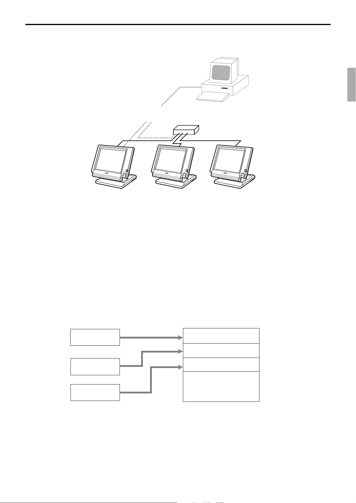
2-12-6. Transferring IDC
It is possible to do collection of IDC files through inline system. Refer to the terminal
structure as below.
Collection Master Satellite Satellite
Flow of the transferring IDC
1. PC sends Z-lock command by using job command to collection master.
PC enables to check the Z-lock confirmation.
2. PC sends the consolidation command by using Job command to collect IDC files from
all satellite terminals.
3. Collection master receives the IDC data from each satellite in order.
PC enables to check whether the collection master has finished the job.
4. PC sends the Z-command or X-command to the collection master.
5. PC receives the collection data from consolidation file. If the Z-command has issued
at step 4, consolidation file in the collection master are all reset.
PC
Via COM 1 port of the master terminal (direct/Modem)
or Inline (Ethernet)
Data transferring flow
IDC data in each terminal totalizer is appended to the consolidation file individually.
Master file
Satellite (1) file
Satellite (2) file
Notes:
• Just after IDC starts, the total file is cleared to receive new data.
• Just after the receiving is over, the data is remained in the consolidation file. To clear
this data, send the Z-command or the file-clear command to the collection master from
the PC. (Set “No”, to “Reset consolidation total after inline consolidation” in the
programming the communication in the machine feature programming.
• In case of collection Z, all of the IDC files in the satellite terminals are cleared.
Copy
Append
Append
Consolidation file (in Collection Master)
Data from Master Totalizer
Data from Satellite (1)
Data from Satelite (2)
•
•
•
QT-6100 Reference Manual
R-77
Page 78

Application System
2-13. Electronic journal
There are two types of electronic journal. One is “normal” electronic journal, the other is
“intelligent” electronic journal. The “normal” electronic journal stores all operations such
as registration, report issuing and programming, but the “intelligent” electronic journal
stores only registration. And the “intelligent” electronic journal stores one receipt when the
transaction is finalized (not stored at new balance). You can select the “normal” or the
“intelligent” electronic journal by allocating the “normal” electronic journal file (file-048
and -648) or the “intelligent” electronic journal file (file-050 and -650)
Electronic journal is stored in the terminal memory, so it is possible to print journal
(electronic journal report) by date or by consecutive number.
And since the journal data is stored in the memory, you can collect journal data from all
terminals in the system. Also, you can issue receipt and guest receipt from electronic
journal.
2-13-1. Storing electronic journal
The electronic journal starts automatically and it ends if the journal memory becomes full.
When the memory becomes full, the terminal alerts end error which you can select to alert
or not to alert by programming. Refer to the page 38 of the programming manual.
Notes:
Even if the electronic journal memory is full, registrations are not disturbed.
2-13-2. Issuing electronic journal report
You can issue both type of the electronic journal read or reset report by date or by
consecutive number.
Refer to the page 145 of this manual.
2-13-3. Displaying electronic journal and producing guest receipts after sales
Pressing the <EJ DISP> key shows the most recent transactions. You can go to older
transactions by pressing the <PAGE UP> key while newer transactions by the <PAGE
DOWN> key. And also you can move lines in a transaction by the <↑> or <↓> key.
During displaying an transaction, you can issue the post receipt of this transaction by
pressing the <RECEIPT> key. If the guest receipt in the original transaction was issued
you can get the copy of the guest receipt by pressing the <RECEIPT> key.
R-78
Page 79
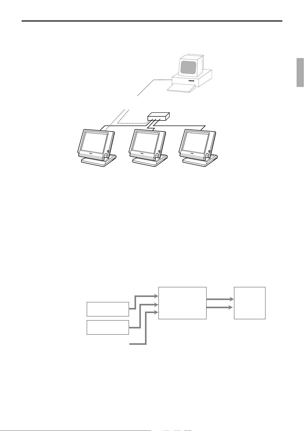
2-13-4. Transferring electronic journal memory
It is possible to do collection of electronic journal files through inline system.
Refer to the terminal structure illustrated below.
Via COM 1 port of the master terminal (direct/Modem)
or Inline (Ethernet)
Collection Master Satellite Satellite
PC
Flow of the transferring electronic journal
1. PC sends the collection command by using Job command to collect electronic journal
file from a satellite terminal.
2. Collection master receives the electronic journal data from a satellite.
PC enables to check whether the collection master has finished the job.
3. PC sends the data send command to the collection master for the collected electronic
journal data.
4. PC receives the collection data from the master. If the Z-command has issued at step
3, electronic journal file in the satellite is all reset.
5. Repeat step 1 ~ 4 for all satellites.
Data transferring flow
Electronic journal data in each terminal is appended to the consolidation file individually.
Copy
Copy
Satellite (1) file
Satellite (2) file
Copy
Consolidation file
(in Collection
Master)
Satellite (1)
Satellite (2)
•
•
•
PC
•
•
•
QT-6100 Reference Manual
File 048 and 648 for “normal” electronic journal.
File 050 and 650 for “intelligent” electrionic journal.
R-79
Page 80

Application System
R-80
Page 81

3. Manager operation ................................................................................. R-82
3-1. Machine initialization ............................................................................. R-82
3-1-1. INIT ............................................................................................................... R-82
3-1-2. Flag clear ...................................................................................................... R-82
3-1-3. INIT 2 ............................................................................................................ R-83
3-1-4. INIT code ...................................................................................................... R-83
3-2. IPL (Initial Program Loading) ................................................................ R-83
3-2-1. IPL ................................................................................................................. R-83
3-2-2. System configuration before IPL operation ................................................... R-84
3-2-3. IPL operation ................................................................................................. R-85
3-3. Manager function ................................................................................... R-86
3-3-1. System connection check ............................................................................. R-86
3-3-2. Remote on .................................................................................................... R-87
3-3-3. Remote off .................................................................................................... R-87
3-3-4. Busy reset ..................................................................................................... R-88
3-3-5. Stock maintenance ....................................................................................... R-89
3-3-6. Drawer for clerk ............................................................................................. R-90
3-3-7. CHK# (Clerk interrupt) .................................................................................. R-90
3-3-8. Order ID change ........................................................................................... R-91
3-3-9. Error log print ................................................................................................ R-92
3-3-10. System re-configuration ................................................................................ R-93
3-3-11. Item Data Capture......................................................................................... R-94
3-3-12. Euro change over .......................................................................................... R-95
3-3-13. Clerk window ................................................................................................. R-96
3-3-14. Customer ...................................................................................................... R-97
3-3-15. Customer busy reset ..................................................................................... R-98
3-3-16. Sound ............................................................................................................ R-98
3-3-17. Clerk number ................................................................................................ R-99
3-3-18. Operation monitor ......................................................................................... R-99
3-3-19. FTP client ................................................................................................... R-99-1
3-4. System command execution............................................................... R-100
3-4-1. X/Z reporting ............................................................................................... R-100
3-4-2. X/Z collection / consolidation ...................................................................... R-101
3-4-3. Remote power control ................................................................................. R-102
3-5. Data communication system .............................................................. R-103
3-5-1. Inline / online connectors ............................................................................ R-103
3-5-2. Hardware interface...................................................................................... R-104
3-5-3. Inline / online functions ............................................................................... R-106
3-6. Collection / Consolidation system ..................................................... R-107
3-6-1. X/Z collection .............................................................................................. R-109
3-6-2. X/Z consolidation ......................................................................................... R-111
3-6-3. X/Z collection / consolidation ...................................................................... R-113
3-7. Auto-programming function ............................................................... R-116
3-7-1. Auto-programming functions ....................................................................... R-116
3-7-2. Auto-program operation and CF card utilities ............................................. R-117
QT-6100 Reference Manual
R-81
Page 82

Manager Operation
3. Manager operation
This section describes manager operations (such as machine initialization, IPL, manager
functions etc.) of QT-6100.
3-1. Machine initialization
There are three different types of initialization such as INIT, FC, and INIT2.
INIT; Machine initialization, all program and total data are reset.
FC; Flag clear, all program and total data are remained, only the current transaction data
are reset.
INIT2; Machine initialization 2, all program data are remained, only total data are reset.
The procedures of machine initialization are described in the chapter 1 of the programming
manual. The required passwords are listed below.
Operation Password Digit meaning
Init
Flag clear No need
Init2 8888888888
* See the “INIT code” section to notice the detail information of the last four digits.
00020000 for the U.S.
00010000 for other area (default descriptors are initialized in English)
00040000 for other area (default descriptors are initialized in German)
00050000 for other area (default descriptors are initialized in French)
00060000 for other area (default descriptors are initialized in Spanish)
00080000 Arabic (default descriptors are initialized in English)
3-1-1. INIT
Start
3-1-2. Flag clear
Initialization process is as follows:
Input password
(see above)
File creation 1
Revise terminal
connection table
Hardware reset
All RAM reset
Initialization operation
Input date/time, ID etc.
Receiving program
f
rom other terminal or
CF card
Flag clear process is as follows:
Inline ID definition
File creation 2
Initialization result
to E-journal
End
R-82
Start
Hardware reset
Initialize work area/
buffers/flags
Menu selection
FC/Init2
Initialization result
to E-journal
Init 2
End
Page 83

3-1-3. INIT 2
Initialization 2 process is as follows:
Start
3-1-4. INIT code
Area code:
U.S. : 2
Other area (default descriptor in English) : 1
always 0
COM3
Not use remote display : 0
Use remote display : 3
always 0
always 0
Hardware reset
Initialize work area/
buffers/flags
Description Choice Program code
(default descriptor in German) : 4
(default descriptor in French) : 5
(default descriptor in Spanish) : 6
(using Arabic character table) : 8
Menu selection
FC/Init2
All totoalizer reset
including E-journal
Flag clear
Significant
number
Significant
number
Significant
number
Significant
number
Significant
number
:
D
;
D
:
D
;
D
;
D
End
5
4
3
2
1
3-2. IPL (Initial Program Loading)
IPL should be made before initializing when the application software has been modified.
3-2-1. IPL
Initial program loading process is as follows: IPL code = 44449999
Start
QT-6100 Reference Manual
ROM check
Waiting for
Communication
port selection
IPL by CF card
IPL
Baud rate
selection
Store the receiving
data to Flash
Continue
to INIT
R-83
Page 84

Manager Operation
CF card
IPL source
IPL target
IPL Data
CF card slot is located
on the backside of the terminal.
3-2-2. System configuration before IPL operation
Connect source terminal (cash register terminal/PC) and target terminals or insert the IPL CF
card to the terminal.
IPL source
IPL target
IPL Data
COM 1 port
PC
R-84
Page 85

3-2-3. IPL operation
xxxxxxx
xxxxxxx IPL : CF CARD
xxxxxxx
xxxxxxx
xxxxxxx
xxxxxxx IPL : COM1 PORT
xxxxxxx
xxxxxxx
(using COM PORT)
xxxxxxx
xxxxxxx 115200 bps
xxxxxxx 57600 bps
56000 bps
IPL : COM1 PORT 34800 bps
19200 bps
9600 bps
CANCEL
If you select “CF card”, insert the CF card into the slot before
this step.
1. Select the appropriate method to loading IPL data.
2. If you choose COM port or IN LINE port, select baud rate of
the IPL source device.
xxxxxxx
xxxxxxx
xxxxxxx
xxxxxxx
xxxxxxx
START
CANCEL
3. Press the <START> key to proceed, in case of downloading
via inline, automatic ID definition is made by this timing. So
press the <YES> key terminal by terminal.
4. After finishing IPL, machine initialization is necessary.
QT-6100 Reference Manual
R-85
Page 86

Manager Operation
3-3. Manager function
Using the manager function makes it possible to control the terminal conditions. The
contents of the manager function are as follows:
1. System connection check
2. Remote on
3. Remote off
4. Busy reset
5. Stock maintenance
6. Drawer for clerk
7. CHK# (Clerk interrupt)
8. Order ID change
9. Error log print
10. System re-configuration
11. Item Data Capture
12. EURO Change over.
13. Clerk window
14. Customer
15. Customer Busy Reset
16. Recording
17. Clerk number
18. Operation monitor
19. FTP client
3-3-1. System connection check
This command shows the connection status of terminals, and printers.
MGR C01 10-10-01 12:34 000000
Manager Mode
1.System Connection Check
2.Remote On
3.Remote Off
4.Busy Reset
5.Stock Maintenance
6.Drawer for Clerk
7.CHK#(CLK Interrupt)
8.Order ID Change
↓
0.00
System Connection Check
INLINE 312Kbps
#01 MC#01
RS-232C Printer 1 2 4
#02 MC#02
RS-232C Printer 1
#03 MC#03
RS-232C Printer *
1. Sign on a clerk (if necessary).
2. Press <Manager> to assign manager mode.
3. Select “1. System Connection Check” and press the <YES>
key.
Physical ID, Logical ID
RS-232C printer recognition (1: printer (1), 2: printer (2), 4: slip printer
Un recognized RS-232C printer
R-86
0.00
4. After checking the system connection, press the <ESC> key
to return the previous menu.
Note:
If there is unrecognized terminal there it shows “*” as below.
example) #04 ************
Page 87
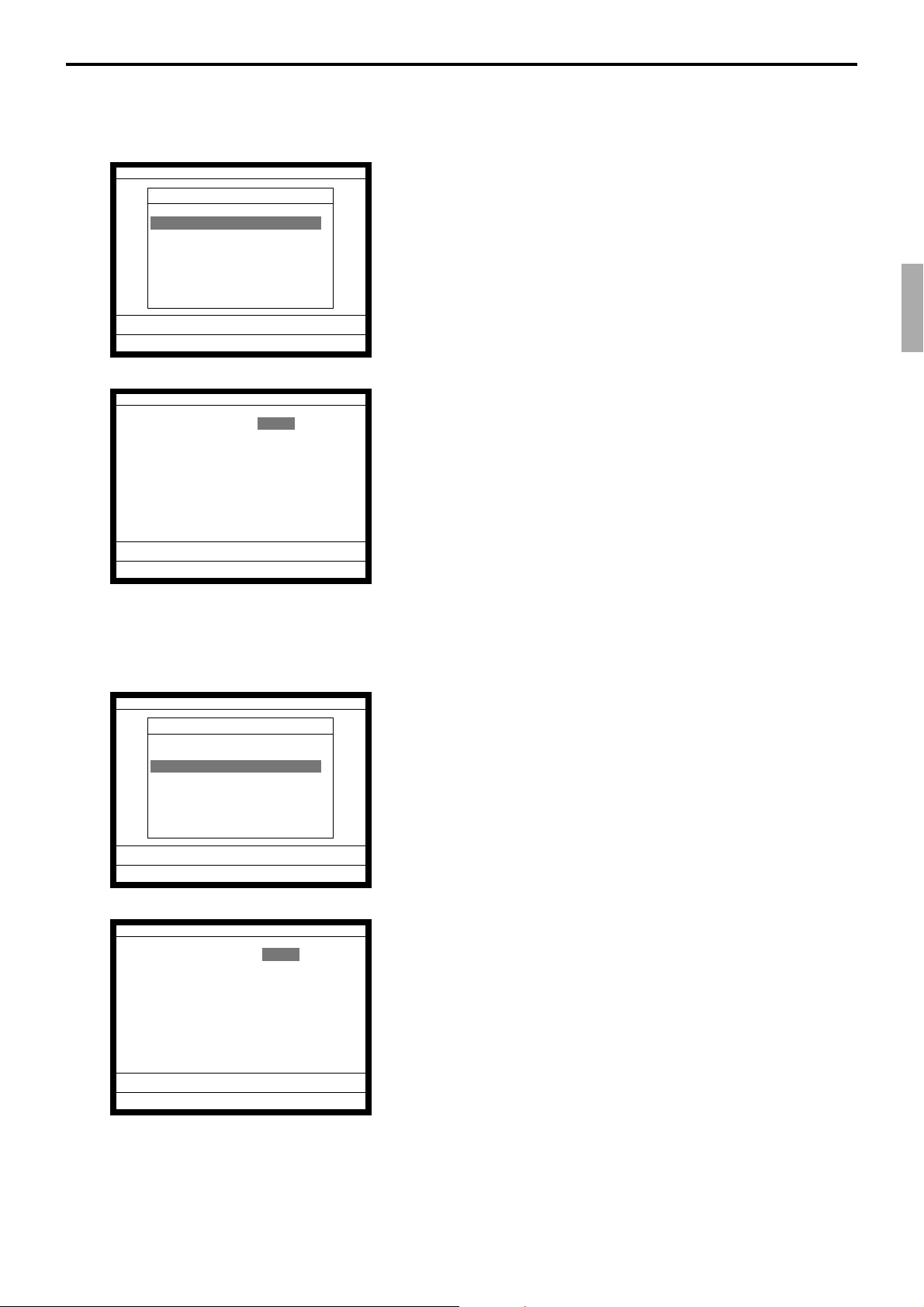
3-3-2. Remote on
This command is used to power on the terminals connected with the same inline.
MGR C01 10-10-01 12:34 000000
Manager Mode
1.System Connection Check
2.Remote On
3.Remote Off
4.Busy Reset
5.Stock Maintenance
6.Drawer for Clerk
7.CHK#(CLK Interrupt)
8.Order ID Change
↓
0.00
Remote On
Terminal All
OK? YES
0.00
1. Sign on a clerk (if necessary).
2. Press <Manager> to assign manager mode.
3. Select “2. Remote On” and press the <YES> key.
4. Select all terminals or individual terminal, select “YES” to
execute this command.
3-3-3. Remote off
MGR C01 10-10-01 12:34 000000
Manager Mode
1.System Connection Check
2.Remote On
3.Remote Off
4.Busy Reset
5.Stock Maintenance
6.Drawer for Clerk
7.CHK#(CLK Interrupt)
8.Order ID Change
0.00
Remote Off
Terminal All
OK? YES
This command is used to power off the terminals connected with the same inline.
1. Sign on a clerk (if necessary).
2. Press <Manager> to assign manager mode.
↓
3. Select “3. Remote Off” and press the <YES> key.
0.00
QT-6100 Reference Manual
4. Select all terminals or individual terminal, select “YES” to
execute this command.
R-87
Page 88

Manager Operation
3-3-4. Busy reset
This command is used to release the busy flag of the check used by other dead terminal.
Executing this command always releases this flag, so please be careful to perform this
operation.
MGR C01 10-10-01 12:34 000000
Manager Mode
1.System Connection Check
2.Remote On
3.Remote Off
4.Busy Reset
5.Stock Maintenance
6.Drawer for Clerk
7.CHK#(CLK Interrupt)
8.Order ID Change
↓
0.00
Busy Reset
Check No. 12
OK? YES
0.00
Busy Reset
Check No. 12
OK? YES
Normal End
1. Sign on a clerk (if necessary).
2. Press <Manager> to assign manager mode.
3. Select “4. Busy Reset” and press the <YES> key.
4. Enter the appropriate check number, and then select “YES”
to execute this command.
R-88
0.00
Page 89

3-3-5. Stock maintenance
This command is used to update PLU stock quantities brought by purchasing or inventory
processing.
MGR C01 10-10-01 12:34 000000
Manager Mode
1.System Connection Check
2.Remote On
3.Remote Off
4.Busy Reset
5.Stock Maintenance
6.Drawer for Clerk
7.CHK#(CLK Interrupt)
8.Order ID Change
↓
0.00
Stock Maintenance
PLU
1.PLU0001
2.PLU0002
3.PLU0003
4.PLU0004
5.PLU0005
6.PLU0006
7.PLU0007
8.PLU0008
↓
0.00
1. Sign on a clerk (if necessary).
2. Press <Manager> to assign manager mode.
3. Select “5. Stock Maintenance” and press the <YES> key.
4. Select the appropriate PLU and press the <YES> key.
No. Descriptor Stock
1 PLU0001 0.000
0.000
No. Descriptor Stock
1 PLU0001 +100.000
100.000
2 PLU0002 0.000
0.000
0.00
PLU0001 +100.000
Entered stock quantity
Total stock quantity
5. Enter adjustment (adding) stock value and press the <YES>
key. If you want to decrease stock value, press the <RF> key
before entering the stock value.
The next PLU appears on the screen.
6. Press the <ESC> key to terminate this sequence.
7. Press the <ESC> key to issue receipt.
RECEIPT
Stock Maintenance
No. Descriptor Stock
--------------------------------------- 1 PLU0001 +100.000
100.000
2 PLU0002 0.000
0.000
QT-6100 Reference Manual
R-89
Page 90
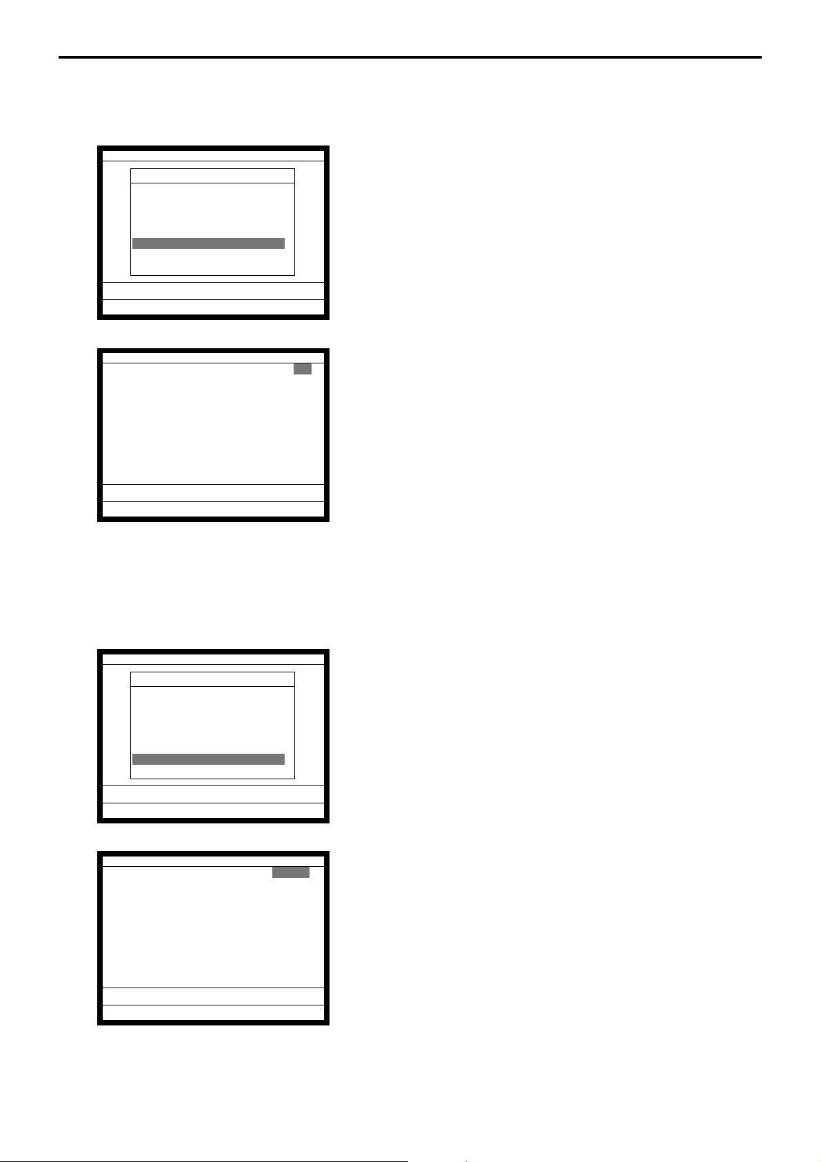
Manager Operation
3-3-6. Drawer for clerk
This command is used to designate the drawer 1 ~ 2.
MGR C01 10-10-01 12:34 000000
Manager Mode
1.System Connection Check
2.Remote On
3.Remote Off
4.Busy Reset
5.Stock Maintenance
6.Drawer for Clerk
7.CHK#(CLK Interrupt)
8.Order ID Change
↓
0.00
Drawer for Clerk
C
01 0
C
02 0
C
03 0
C
04 0
C
05 0
C
06 0
0.00
1. Sign on a clerk (if necessary).
2. Press <Manager> to assign manager mode.
3. Select “6. Drawer for Clerk” and press the <YES> key.
The display shows “Clerk name/Drawer No.” list.
4. Select the drawer No. field of the appropriate clerk, enter the
drawer number (1 or 2, “0” means drawer 1), and press the
<YES> key.
5. Press the <ESC> key to return to the previous menu.
3-3-7. CHK# (Clerk interrupt)
This command is used to designate the check number for clerk interrupt to each clerk.
MGR C01 10-10-01 12:34 000000
Manager Mode
1.System Connection Check
2.Remote On
3.Remote Off
4.Busy Reset
5.Stock Maintenance
6.Drawer for Clerk
7.CHK#(CLK Interrupt)
8.Order ID Change
0.00
CHK#(CLK Interrupt)
C
01 011111
C
02 022222
C
03 033333
C
04 044444
C
05 055555
C
06 066666
1. Sign on a clerk (if necessary).
2. Press <Manager> to assign manager mode.
↓
3. Select “7. CHK# (CLK Interrupt)” and press the <YES> key.
The display shows “Clerk name / Check No.” list.
4. Select the check No. field of the appropriate clerk, enter the
check number (within 6-digits), and press the <YES> key.
5. Press the <ESC> key to return the previous menu.
R-90
0.00
Page 91

3-3-8. Order ID change
This command is used to change the target printer of order temporarily.
MGR C01 10-10-01 12:34 000000
Manager Mode
1.System Connection Check
2.Remote On
3.Remote Off
4.Busy Reset
5.Stock Maintenance
6.Drawer for Clerk
7.CHK#(CLK Interrupt)
8.Order ID Change
↓
0.00
Order ID Change
Definition Enable YES
1.Order1 103
2.Order2 202
3.Order3 203
4.Order4 104
5.Order5 000
6.Order6 000
7.Order7 000
OK? YES
0.00
1. Sign on a clerk (if necessary).
2. Press <Manager> to assign manager mode.
3. Select “8. Order ID Change” and press the <YES> key.
D3D2D
1
“Order 7” cannot be used.
4. Select “YES” of the Definition Enable field, and enter an
appropriate ID number of each order printer and press the
<YES> key. Select “YES” of the last line to execute this
command.
Note: D
3 D2 D1
In case of D3 = 1, D2 & D1 defines the terminal physical ID that connect to printer-1.
In case of D3 = 2, D2 & D1 defines the terminal physical ID that connect to printer-2.
In case of D3 = 3, D2 & D1 defines the terminal physical ID that connect to printer-3.
QT-6100 Reference Manual
R-91
Page 92

Manager Operation
3-3-9. Error log print
This command is used to display / print out the error log file.
MGR C01 10-10-01 12:34 000000
Manager Mode
3.Remote off
4.Busy Reset
5.Stock Maintenance
6.Drawer for Clerk
7.CHK#(CLK Interrupt)
8.Order ID Change
9.Error Log Print
10.System Re-configuration
↑
↓
0.00
ID Date Time OPE ERR JOB
#01 MC #01 0603 1535 1 51 38
#03 MC #03 0603 1535 22 235 22
0.00
Error Log Print
Do you want to printout? YES
1. Sign on a clerk (if necessary).
2. Press <Manager> to assign manager mode.
3. Select “9. Error Log Print” and press the <YES> key.
4. The display shows current error log.
Then press the <ESC> key.
0.00
5. Press the <YES> key if you want to print error log.
If you do not want to print error log, press the <ESC> key.
RECEIPT
Error Log Print
ID Date Time OPE ERR JOB
---------------------------------------#01 MC #01 0603 1535 1 51 38
#03 MC #03 0603 1535 22 235 22
#00 0000 0000 0 0 0
R-92
Page 93
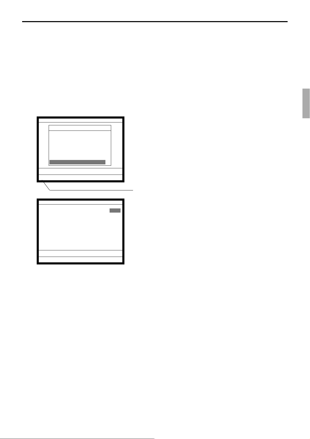
3-3-10. System re-configuration
This command is one procedure of down recovery. It backs the contents of the system
connection table to the original value.
It should be executed under these conditions:
1) After issuing “Open check report”.
2) All terminals are connected and work without any trouble. (Check by system connection
check)
3) No terminal is in registration, collection, consolidation, sending/receiving programs.
4) Activate “System re-configuration” command at the terminal on which the “Cut-off”
icon is lit.
MGR C01 10-10-01 12:34 000000
Manager Mode
3.Remote off
4.Busy Reset
5.Stock Maintenance
6.Drawer for Clerk
7.CHK#(CLK Interrupt)
8.Order ID Change
9.Error Log Print
10.System Re-configuration ↓
↑
1. Sign on a clerk (if necessary).
2. Press <Manager> to assign manager mode.
0.00
ß
Cut-off Master or Backup master icon
System Re-configuration
System Re-configuration NO
OK? YES
0.00
ß
3. Select “10. System Re-configuration” and press the <YES>
key.
4. Choose the option “YES (Perform system re-configuration)
/ NO (Abort this procedure)” and press the <YES> key.
QT-6100 Reference Manual
R-93
Page 94

Manager Operation
3-3-11. Item Data Capture
You can change the IDC status (capture transaction data or not) by the operation described
below.
MGR C01 10-10-01 12:34 000000
Manager Mode
9.Error Log Print
10.System Re-configuration
11.Item Data Capture
12.EURO Change over
13.Clerk Window
14.Customer
15.Customer Busy Reset
16.Recording
↑
↓
0.00
Item Data Capture
Item Data Capture YES
0.00
1. Sign on a clerk (if necessary).
2. Press <Manager> to assign manager mode.
3. Select “11. Item Data Capture” and press the <YES> key.
4. Choose the option “YES (capture item data) / NO (not capture
item data)” and press the <ESC> key.
R-94
Page 95
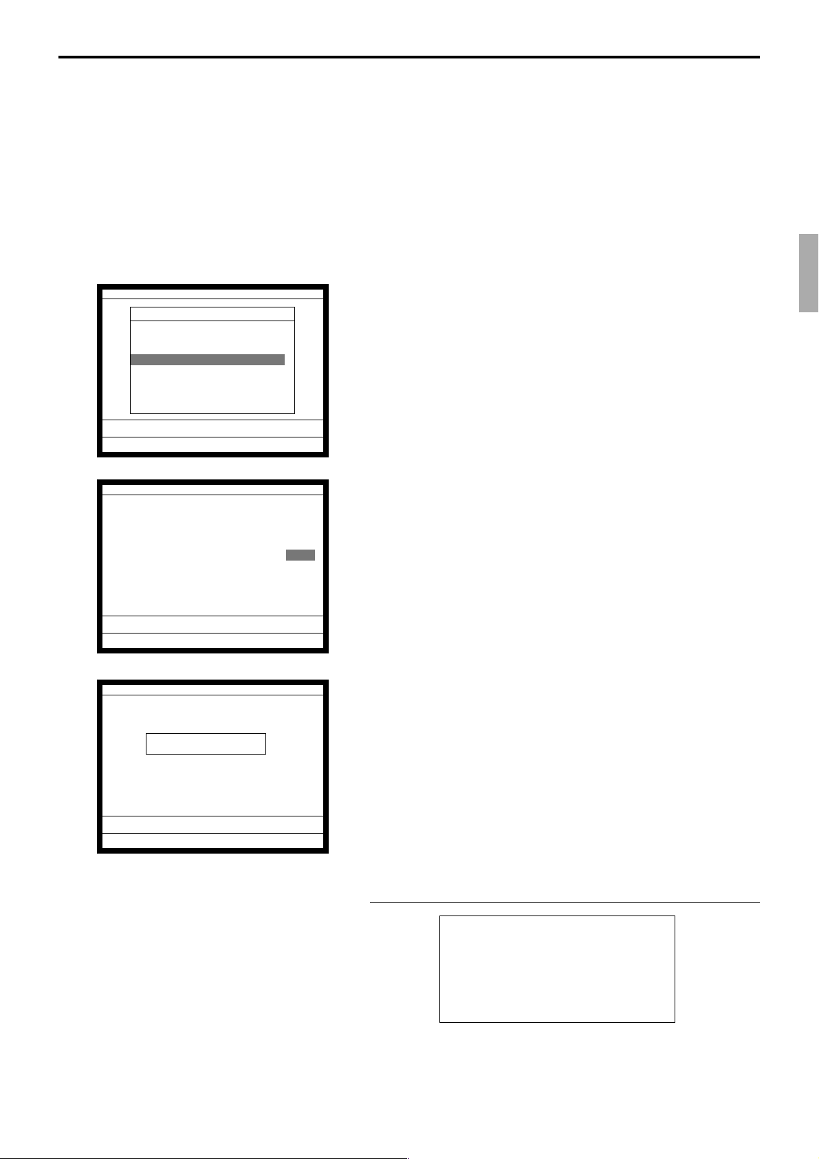
3-3-12. Euro change over
After this operation, the following subjects are made:
(1) The Euro is defined as main currency and the local is defined as sub currency.
(2) All totals and counts are reset.
(3) Unit prices (department, subdepartment, PLU, 2nd @, shift PLU) are converted
in Euro.
Before “change over operation”,
(1) Issue all reset report including open check report, if necessary.
(2) Sign off all cashier/clerk and stop all operations of all terminals of the system.
MGR C01 10-10-01 12:34 000000
Manager Mode
9.Error Log Print
10.System Re-configuration
11.Item Data Capture
12.EURO Change over
13.Clerk Window
14.Customer
15.Customer Busy Reset
16.Recording
↑
↓
0.00
EURO Change over
This operation will clear all
of totalizer and change over
EURO/LOCAL system.
Are you sure want to execute
these job? YES
0.00
EURO Change over
1. Sign on a clerk (if necessary).
2. Press <Manager> to assign manager mode.
3. Select “12. EURO Change over” and press the <YES> key.
4. If you want to proceed this step, press the <YES> key. To
abort this step, press the <NO> or <ESC> key.
Operation Code ?
0.00
QT-6100 Reference Manual
5. If you want to proceed this step, enter “8888888888” and
press the <YES> key. (It takes a few minutes.)
To abort this step, press the <NO> or <ESC> key.
RECEIPT
EURO Change over
Done update EURO rate and
symbols.
Please check unit price and
fix totalizer euro-in-drawer
title character.
Perform the same operation of all the terminals of the system.
R-95
Page 96
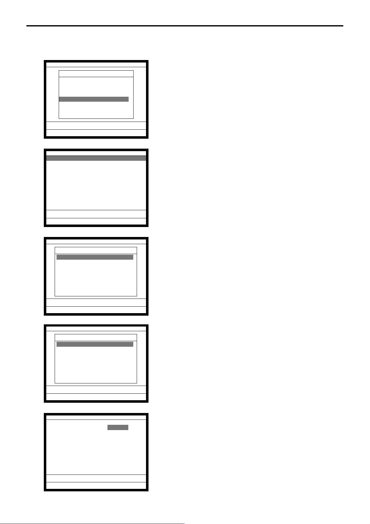
Manager Operation
3-3-13. Clerk window
You can program clerk window contents in the MGR mode.
MGR C01 10-10-01 12:34 000000
Manager Mode
9.Error Log Print
10.System Re-configuration
11.Item Data Capture
12.EURO Change over
13.Clerk Window
14.Customer
15.Customer Busy Reset
16.Recording
↑
↓
0.00
Clerk Window
Clerk Window (Disable)
0.00
Clerk Window
Clerk Window
1.(Disable)
2.Clerk window 1
3.Clerk window 2
4.Clerk window 3
5.Clerk window 4
6.Clerk window 5
7.Clerk window 6
8.Clerk window 7 ↓
1. Sign on a clerk (if necessary).
2. Press <Manager> to assign manager mode.
3. Select “13.Clerk Window” and press the <YES> key.
4. Press the <YES> key to continue.
0.00
Key Assign
Clerk window 1
1.(Clerk reset)
C
2.
3.
4.
5.
6.
7.
8.
01
C
02
C
03
C
04
C
05
C
06
C
07 ↓
0.00
Key Assign
OK? YES
0.00
5. Select the clerk window. If you don’t use clerk window,
select “1.(Disable)”.
6. Select the clerk to allocate the clerk window. After this
operation, select the appropriate key in the clerk window.
7. Press the <YES> key to set this program.
R-96
Page 97

3-3-14. Customer
You can program (add / modify / delete) the customer (name, address etc.) in the MGR
mode.
MGR C01 10-10-01 12:34 000000
Manager Mode
9.Error Log Print
10.System Re-configuration
11.Item Data Capture
12.EURO Change over
13.Clerk Window
14.Customer
15.Customer Busy Reset
16.Recording
↑
↓
0.00
Cust No. Name
0 (New customer)
11111 Mr. John SMITH
22222 Mrs. Jane Parker
33333 Ms. Janet Lynn
0.00
1. Sign on a clerk (if necessary).
2. Press <Manager> to assign manager mode.
3. Select “14.Customer” and press the <YES> key.
4. Add customer: Select (New customer) and press the <YES>.
Then input the customer No. and press the <YES> in the next
screen.
Modify customer: Select the appropriate customer and press
the <YES>.
Delete customer: Select the appropriate customer and press
the <NO>.
• If you swipe a card at this timing, “add customer (new card)”
or “modify customer (already programmed card) is performed.
Cust No. 123456
Name
Title
Address(1)
Address(2)
Address(3)
Address(4)
Phone No.
Customer GP Group01
New customer YES
0.00
—— Customer name (up to 24 characters)
—— Customer title (select from sub menu)
—— Customer address 1 (up to 24 characters)
—— Customer address 2 (up to 24 characters)
—— Customer address 3 (up to 24 characters)
—— Customer address 4 (up to 24 characters)
—— Customer phone No. (up to 12 digits)
—— Customer group (select from sub menu)
5. Press the <ESC> to set and continue to program new customer.
QT-6100 Reference Manual
R-97
Page 98
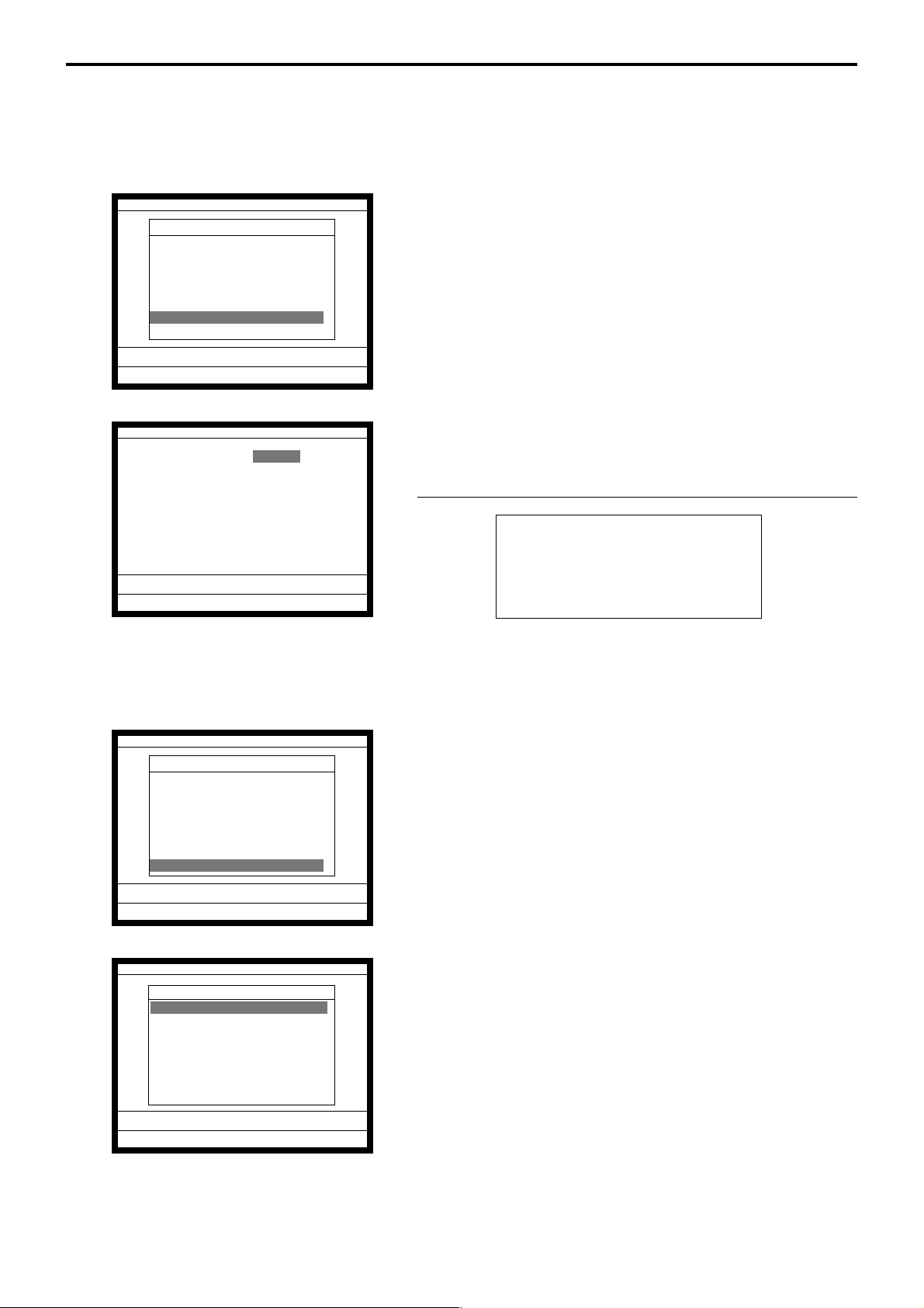
Manager Operation
3-3-15. Customer busy reset
This command is used to release the busy flag of the customer used by other dead terminal.
Executing this command always releases this flag, so please be careful to perform this
operation.
MGR C01 10-10-01 12:34 000000
Manager Mode
9.Error Log Print
10.System Re-configuration
11.Item Data Capture
12.EURO Change over
13.Clerk Window
14.Customer
15.Customer Busy Reset
16.Recording
↑
0.00
Customer Busy Reset
Cust No.
OK? YES
0.00
1. Sign on a clerk (if necessary).
2. Press <Manager> to assign manager mode.
3. Select “15. Customer Busy Reset” and press the <YES> key.
4. Enter the appropriate customer number, and then select
“YES” to execute this command.
RECEIPT
Busy Reset
CUST No.
123456
Dr.
Big Scientist
BALANCE
DISCOUNT $3.23
$45.90
3-3-16. Sound
MGR C01 10-10-01 12:34 000000
Manager Mode
9.Error Log Print
10.System Re-configuration
11.Item Data Capture
12.EURO Change over
13.Clerk Window
14.Customer
15.Customer Busy Reset
16.Recording
0.00
Recording
WAV File
1.Sound (1)
2.Sound (2)
3.Sound (3)
4.Sound (4)
5.Sound (5)
6.Sound (6)
7.Sound (7)
8.Sound (8) ↓
0.00
QT-6100 does not have Microphone and speaker. This feature does not work.
↑
↓
R-98
Page 99

3-3-17. Clerk number
MGR C01 10-10-01 12:34 000000
C
001111
002222
003333
004444
C
01 097
C
02 098
C
03 099
C
04 100
Hard key code
04 0
You can program clerk number directly to the <CLK#> key in the MGR mode.
1. Sign on a clerk (if necessary).
2. Press <Manager> to assign manager mode.
3. Enter “00” and the clerk number you want to set and press the
appropriate <CLK#> key.
(Entering “000000” clears the clerk number program.)
4. To terminate this step, press the <ST> key.
3-3-18. Operation monitor
You can monitor a clerk’s operation by monitoring display and receipt (in case of
connecting printer).
MGR C01 10-10-01 12:34 000000
Start... 0.00
1. Sign on a clerk (if necessary).
2. Press <Manager> to assign manager mode.
3. Enter “99990000nn (nn: terminal ID No. to monitor)” and
press the <ST> to start operation monitor.
Note: Do not designate the monitored or monitoring terminal.
The display shows the screen of the monitored terminal.
The receipt shows the printout of the monitored terminal.
4. Press <ESC> twice break the monitoring.
QT-6100 Reference Manual
R-99
Page 100

Manager Operation
3-3-19. FTP client
You can execute FTP client processing by the operation below.
MGR C01 10-10-01 12:34 000000
Manager Mode
10.System Re-configuration
11.Item Data Capture
12.EURO Change over
13.Clerk Window
14.Customer
15.Customer Busy Reset
16.Recording
17.FTP Client
0.00
FTP Client
FTP SERVER
1.HEAD OFFICE
2.FTP SERVER 2
3.FTP SERVER 3
4.FTP SERVER 4
5.FTP SERVER 5
6.FTP SERVER 6
7.FTP SERVER 7
8.FTP SERVER 8 ↓
↑
1. Sign on a clerk (if necessary).
2. Press <Manager> to assign manager mode.
3. Select “17. FTP Client” and press the <YES> key.
0.00
FTP Client
FTP FILE
1.FTP FILE 1
2.FTP FILE 2
3.FTP FILE 3
4.FTP FILE 4
5.FTP FILE 5
6.FTP FILE 6
7.FTP FILE 7
8.FTP FILE 8 ↓
0.00
FTP Client
FTP SERVER HEAD OFFICE
FTP FILE Daily PLU
Normal End
0.00
4. Select the appropriate FTP server in the list, and press
<YES>.
5. Select the appropriate FTP file in the list, and press <YES>.
The process programmed in the file 912 / 913 is executed.
6. Check the execution result and press <ESC> to exit.
QT-6100 Reference Manual
R-99-1
 Loading...