

PX-700
INDEX
SEP. 2005
PX-700
ELECTRONIC KEYBOARD
Ver. 9: Jan. 2010

CONTENTS
Specifications ---------------------------------------------------------------------------------------------- 1
Block Diagram --------------------------------------------------------------------------------------------- 2
Circuit Description --------------------------------------------------------------------------------------- 3
Printed Circuit Board ------------------------------------------------------------------------------------ 4
Disassembly ------------------------------------------------------------------------------------------------ 6
Diagnostic Program ------------------------------------------------------------------------------------ 14
Schematic Diagrams ----------------------------------------------------------------------------------- 16
Exploded View ------------------------------------------------------------------------------------------- 20
Parts List--------------------------------------------------------------------------------------------------- 22

SPECIFICATIONS
GENERAL
Keyboard: 88 piano keys (with touch response)
Polyphony: 32 notes, maximum
Tones: 11; with layer, split
Digital Effects: Reverb (4 types), Chorus (4 types), DSP, Brilliance
Metronome: • Time Signatures: 0, 2, 3, 4, 5, 6
• Tempo Range: 30 to 255
Music Library: • Number of Tunes: 60
• Tune Volume: Adjustable
• Demo: Sequential looping of all 60 preset tunes
• Part On/Off: Left hand, right hand
Song Memory: • Operations: Real-time recording, playback
• Capacity: Approximately 10,000 notes (2 tracks total)
• Memory Backup: Built-in lithium battery (Battery Life: 5 years)
Pedals: Damper, Soft, Sostenuto
Other Functions: • Touch: 3 types, off
• Transpose: 1 octave (F to C to F)
• Tuning: A4 = 440.0Hz ±50 cents (adjustable)
MIDI: 16 multi-timbre receive
Input/Output: • Headphones: Stereo standard jacks
Output Impedance: 170.
Output Voltage: 5.5V (RMS) MAX
• Power: 12V DC
• MIDI (OUT) (IN)
• Pedal connector
Speakers: 12cm 2 (Output: 8.0W + 8.0W)
Power Supply: AC Adaptor: AD-12
Power Consumption: 12V
18W
Dimensions: Digital piano + stand: 136.9 30.0 78.9 cm (53
Weight: Digital piano + stand: Approximately 32.5 kg (71.6 lbs)
2
15
/
11 13/16 31 1/16 inch)
16
ELECTRICAL
Load condition
Current drain with 12 V DC:
Speaker: 6 . Real Load
Volume: maximum
Tone: Strings
Touch: MAX mode
Keys: A0 - D5, 32poly
Consumption Current 1450 mA ± 20 %
Consumption Current at idle 230 mA ± 20 %
Speaker output level (Vrms with 6 . load each channel):
Tone: TEST MODE (Sin wave MAX L and MAX R)
L ch: 3000 mV ± 20 %
R ch: 3000 mV ± 20 %
Phone output level (Vrms with 32 . load each channel):
Tone: TEST MODE (Sin wave MAX)
L ch: 300 mV ± 20 %
R ch: 300 mV ± 20 %
— 1 —
MAIN PCB (M404-MDA1)
Reset IC
IC5
R1151N001C-TR
RESET
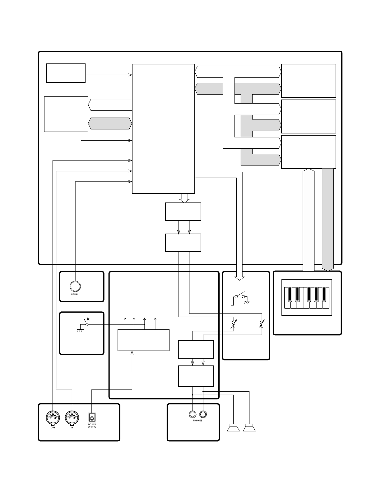
BLOCK DIAGRAM
MA0 ~ MA20
MA0 ~ MA16, 25
MD0 ~ MD7
RAM (1Mbit)
IC4
CY62128DV30LL
RAM (1Mbit)
IC3
CY62128DV30LL
EA0 ~ EA15,EA18
ED12 ~ ED19
16.384MHz
SUB PCB
(M404-PSA1)
MPU
IC7
uPD914AGM-JED
DAC IC15
µPD63200GS-E1
LOUT ROUT
IC8, IC13
Filter
Buttons
MA0 ~ MA20
MD0 ~ MD15
MA0 ~ MA3
MD0 ~ MD15
ROM (64Mbit)
MR27V6402G19RTN03D
IC1
KEY CONTROLLER
IC14
TC190C020AF-001
SI0 ~ SI7
FI0 ~ FI7
Keyboard
KC0 ~ KC7
CONSOLE PCB
(M406-CNA3)
CONSOLE PCB
(M406-CNA4)
(5V)
VA5
VI5
Power Supply Circuit
IC202,Q206,Q207,
D206,D207
D201
VD5
VA12
(12V)
(5V)
(5V)
Filter
IC205
Power Amplifier
IC201
LA4636
CONSOLE PCB
(M406-CNA2)
— 2 —
Main
Volume
CONSOLE PCB
(M406-CNA1)
(L)
(R)
Speakers
Keyboard PCB
(MCPZ-KYA1/KYB2/KYA3)
CIRCUIT DESCRIPTION
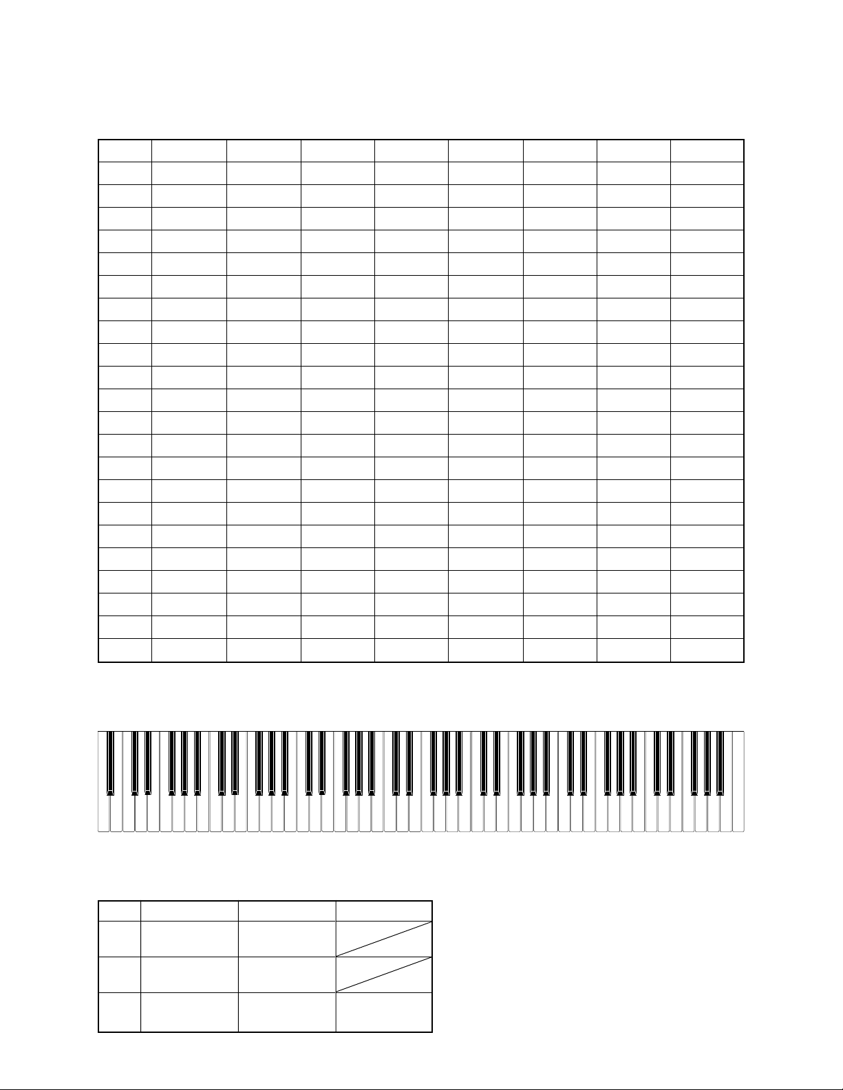
KEY MATRIX
KC0 KC1 KC2 KC3 KC4 KC5 KC6 KC7
FI0 A01 A0#1 B01 C11 C1#1 D11 D1#1 E11
SI0 A02 A0#2 B02 C12 C1#2 D12 D1#2 E12
FI1 F11 F1#1 G11 G1#1 A11 A1#1 B11 C21
SI1 F12 F1#2 G12 G1#2 A12 A1#2 B12 C22
FI2 C2#1 D21 D2#1 E21 F21 F2#1 G21 G2#1
SI2 C2#2 D22 D2#2 E22 F22 F2#2 G22 G2#2
FI3 A21 A2#1 B21 C31 C3#1 D31 D3#1 E31
SI3 A22 A2#2 B22 C32 C3#2 D32 D3#2 E32
FI4 F31 F3#1 G31 G3#1 A31 A3#1 B31 C41
SI4 F32 F3#2 G32 G3#2 A32 A3#2 B32 C42
FI5 C4#1 D41 D4#1 E41 F41 F4#1 G41 G4#1
SI5 C4#2 D42 D4#2 E42 F42 F4#2 G42 G4#2
FI6 A41 A4#1 B41 C51 C5#1 D51 D5#1 E51
SI6 A42 A4#2 B42 C52 C5#2 D52 D5#2 E52
FI7 F51 F5#1 G51 G5#1 A51 A5#1 B51 C61
SI7 F52 F5#2 G52 G5#2 A52 A5#2 B52 C62
FI8 C6#1 D61 D6#1 E61 F61 F6#1 G61 G6#1
SI8 C6#2 D62 D6#2 E62 F62 F6#2 G62 G6#2
FI9 A61 A6#1 B61 C71 C7#1 D71 D7#1 E71
SI9 A62 A6#2 B62 C72 C7#2 D72 D7#2 E72
FI10 F71 F7#1 G71 G7#1 A71 A7#1 B71 C81
SI10 F72 F7#2 G72 G7#2 A72 A7#2 B72 C82
NOMENCLATURE OF KEYS
A#1A#0 G#1F#1D#1C#1 A#6G#6F#6D#6C#6
C1 D1 E1 F1 G1 A1 B1A0 B0
C2 D2 E2 F2 G2 A2 B2 C3 D3 E3 B6A6G6F6E6D6 C7
BUTTON MATRIX
KC0
KC1
KC2
KI0
FUNCTION
START/
STOP
PART/
TRACK
KI1
SONG
MEMORY
METRONOME
SPLIT
D#3
C#3A#2G#2F#2D#2C#2
F#3G#3 A#3 C#4D#4 F#4G#4A#4 C#5D#5 F#5G#5A#5
F3 G3 A3 B3 C4 D4 E4 F4 G4 A4 B4 C5 D5 E5 F5 G5 A5 B5
KI2
GRAND
PIANO
— 3 —
C#7
C6
A#7G#7F#7D#7
B7A7G7F7E7D7 C8
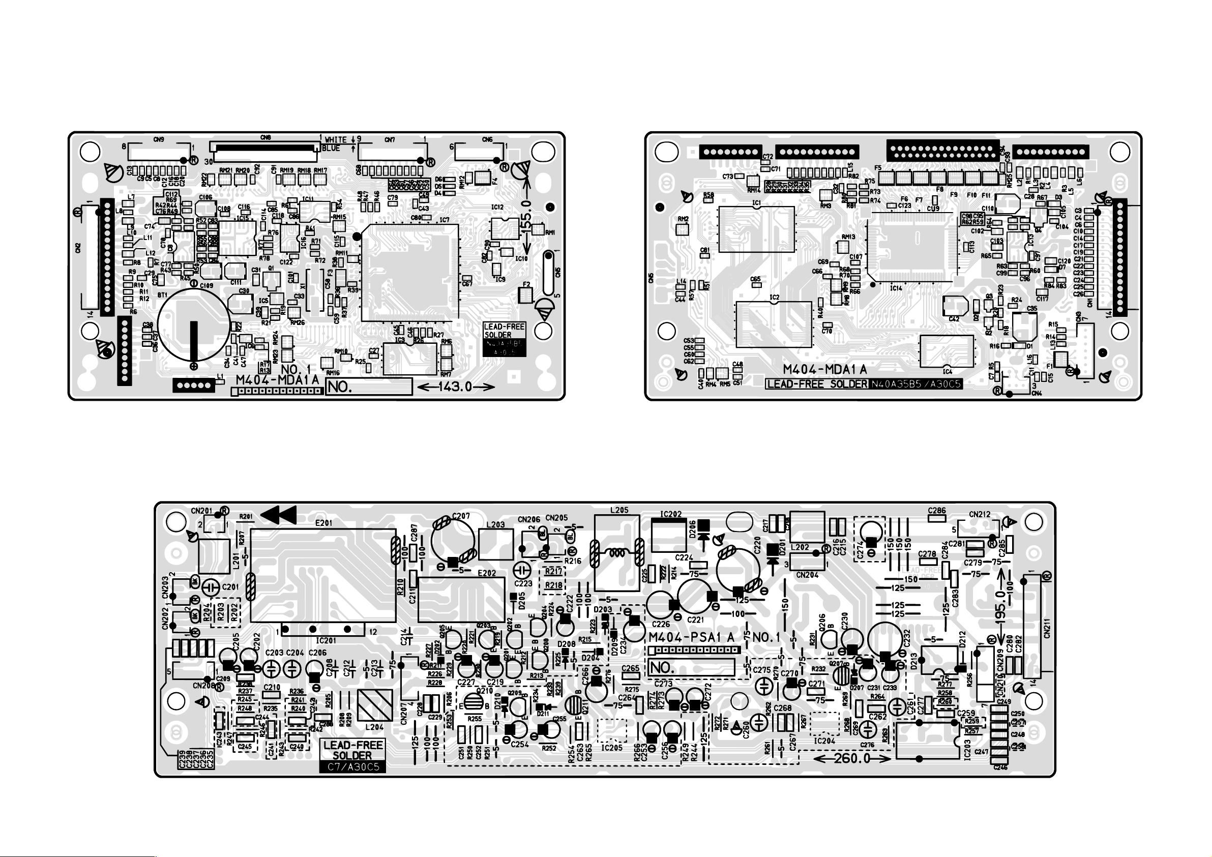
MAIN PCB M404-MDA1
PRINTED CIRCUIT BOARDS
SUB PCB M404-PSA1
Top view
Bottom view
— 4 —
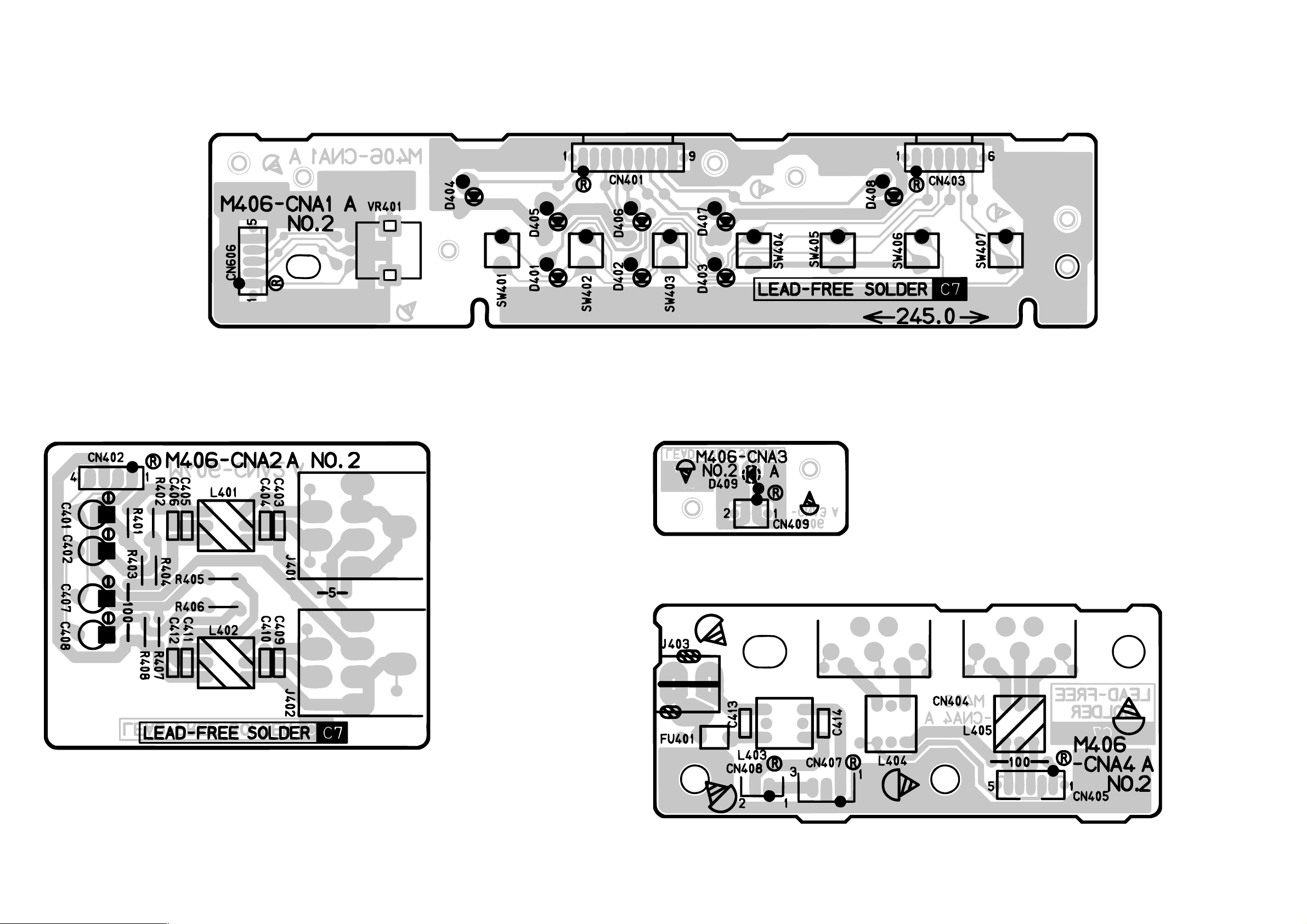
CONSOLE PCB M406-CNA1
CONSOLE PCB M406-CNA2 CONSOLE PCB M406-CNA3
CONSOLE PCB M406-CNA4
— 5 —
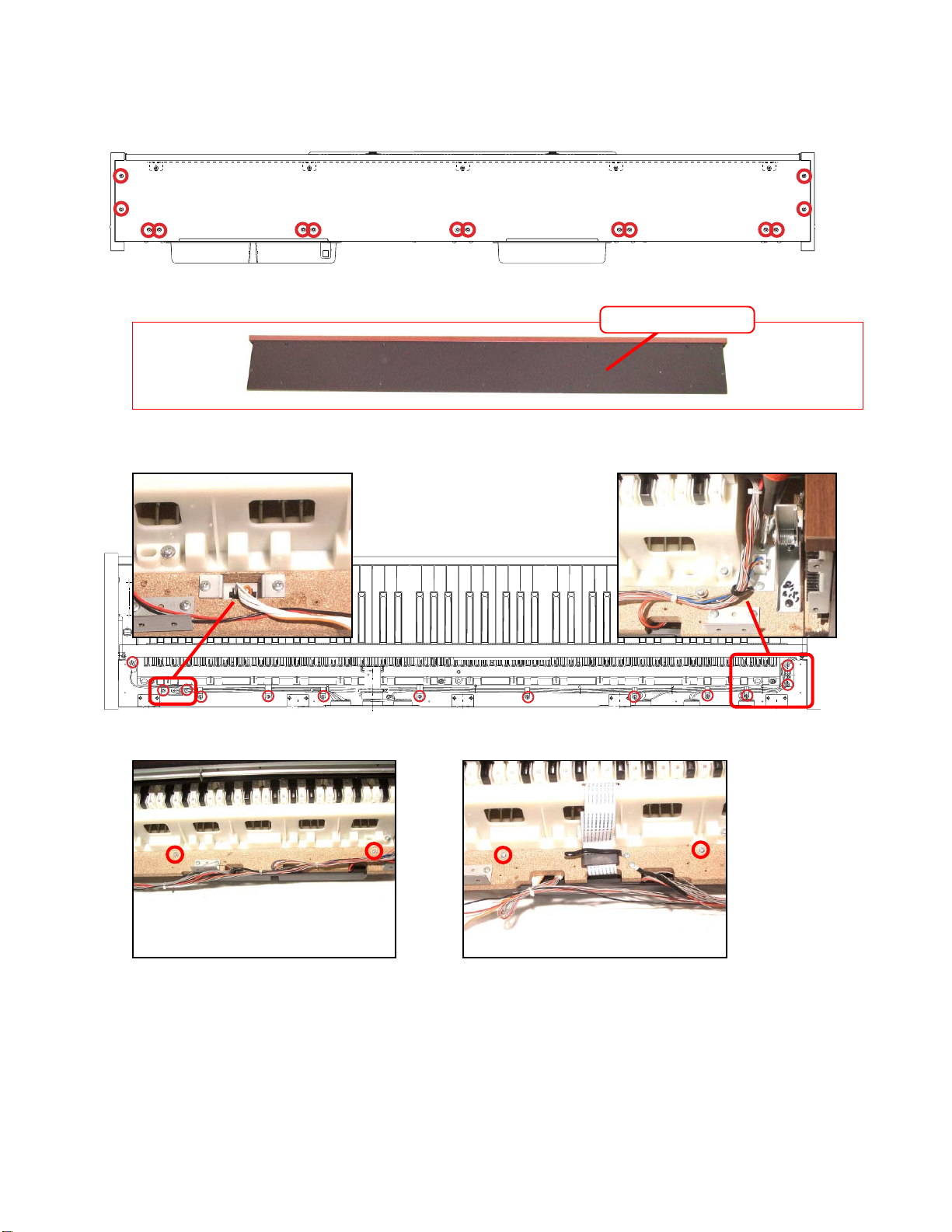
DISASSEMBLY
1. Remove 14 screws and then the lower panel.
2. Remove the T-BRD-UNIT.
■ Removing the PCBs (M404-MDA1, M406-CNA4, M404-PSA1).
3. Remove 13 screws.
T-BRD-UNIT
3. Remove 4 screws.
— 6 —
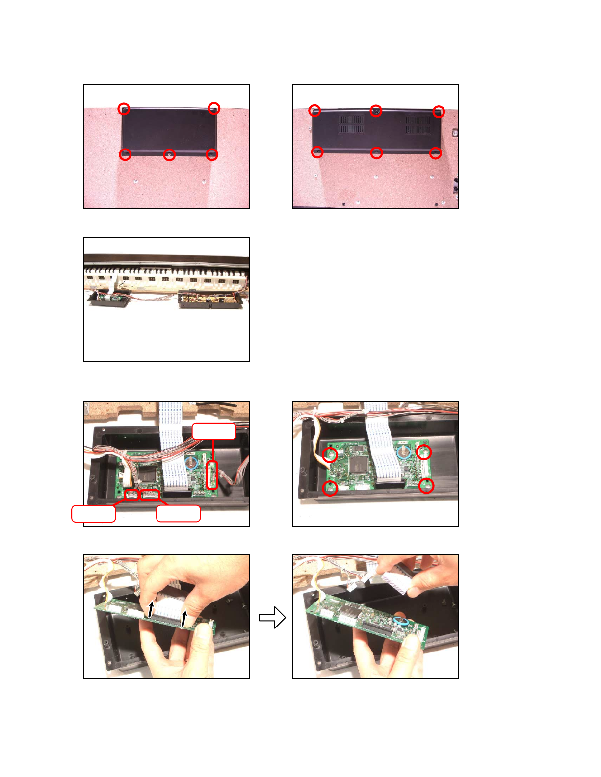
5. Remove 11 screws.
6. Remove the PCB case.
7. Remove 3 connectors.
8. Remove 4 screws.
CN2
CN6
CN7
9. Remove the FPC and then the main PCB (M404-MDA1).
— 7 —

10. Remove 3 connectors and 4 screws.
11. Remove the console PCB (M406-CNA4).
CN405
CN407
CN408
12. Remove 5 connectors and 6 screws.
13. Remove the sub PCB (M404-PSA1).
CN207 CN203
CN206CN212
CN201
Removing the key cover.
14. Remove 2 screws and then both sides of the stoppers.
15. Remove 2 screws and then both sides of the TOP-DECORs.
TOP-DECOR
Stopper
16. Remove the key cover.
2
1
2
— 8 —

* Caution while assembling the key cover.
Removing the key board.
17. Remove 3 screws and then the CN-PANEL ASSY.
18. Remove 24 screws and then the KEY-BOARD ASSY.
— 9 —

Removing the front board.
19. Remove 6 screws on the bottom, and then lift the front board up.
20. Remove 2 screws and then the front board.
Removing the power switch.
21. Remove 2 screws on the bottom.
22. Remove 2 screws and then the power switch.
— 10 —

Removing the power switch.
23. Remove 2 screws on the bottom.
24. Remove 2 screws and then the PCB (M406-CNA2).
25. Remove the volume knob and 2 screws, and then the PCB (M406-CNA1).
— 11 —

Disassembling the key board.
26. Remove 2 screws and then the bracket.
27. Remove the keys.
* Caution while assembling the keys.
Set the key as shown in figures below.
— 12 —

28. Remove 8 rubber keys.
* One of the keys has the different length from others.
* Caution while assembling the rubber keys.
Push the rubber keys with the tool like the tweezers, so the projections of the rubber keys matches with
the holes of the lower case.
29. Remove 9 screws then the PCB (MCPZ-KYA1).
30. Remove 11 screws then the PCB (MCPZ-KYB2).
31. Remove 9 screws then the PCB (MCPZ-KYA3).
MCPZ-KYA1
*SCREW ⋅ 9
MCPZ-KYB2
*SCREW ⋅ 11
MCPZ-KYA3
*SCREW ⋅ 9
— 13 —

DIAGNOSTIC PROGRAM
Initial Setup
1. Connect an AC adaptor.
2. Connect a pedal cord.
3. "Main" volume: MAX.
NOTE: If there is no pedal or MIDI cable, pedal or MIDI check can be skipped.
How to start diagnostic program
1. Turn on the “POWER” button while the “FUNCTION” and the “TRACK1/TRACK2” buttons are depressed.
2. Release the “FUNCTION” and the “TRACK1/TRACK2” buttons.
ALL the LEDs flash and the test mode boots.
Diagnostic program
1. Automatic Test
1 CPU RAM check
2 DSP RAM check
3 ROM check
While performing 1 ~ 3, TONE1, TONE2, TONE3, or START/STOP lights when an error is found in
ROM. If no error is found, the confirmation chord C6 sounds.
2. LED check
1 The LEDs light in the
sequence shown below
when the “FUNCTION”
button is pressed.
LED check repeats if the
“PLAY/RED” is pressed.
4. Pedal check (If there is no Pedal, this check can be skipped.)
1 Press the “FUNCTION” button to perform the “Pedal check.”
2 Press the “SOFT” pedal.
The confirmation chord C4 sounds and “LEFT/TRACK1” LED lights.
3 Press the “SOSTENUTO” pedal.
The confirmation chord E4 sounds and “RIGHT/TRACK2” LED lights.
4 Press the “DAMPER” pedal. (ON HALF)
The confirmation chord G4 sounds and “REC” LED lights.
5 Press the “DAMPER” pedal. (ON FULL)
The confirmation chord G4 sounds and “REC” and “PLAY” LEDs lights.
3. BUTTON check
1 Press the “FUNCTION”
button to perform
“BUTTON check.”
The confirmation chord C6
sounds.
2 Press buttons in the order
following.
NG tone sounds when an
error is found in the
buttons or when the
buttons are pressed in a
wrong order.
This test cannot be
aborted.
— 14 —

5. Headphone check
1 Press “FUNCTION” button to perform the “Headphone check.”
The confirmation chord C6 sounds and “PLAY” LED lights.
2 Connect the headphone to the LEFT jack.
“REC” LED lights.
3 Remove the headphone from the jack.
“PLAY” LED lights.
4 Connect the tuning meter to the RIGHT jack.
“REC” LED lights.
5 Press the “A4” key.
Make sure that the tuning meter is set at 440 ± 2sents.
6 Remove the tuning meter from the jack.
“PLAY” LED lights.
7 Press “FUNTION” button to finish the “headphone check.”
The confirmation chord C6 sounds.
6. MIDI check (If there is no MIDI cable, this check can be skipped.)
1 Press “TONE1” button to perform the “MIDI check.”
NG tone sounds.
2 Connect a MIDI cable.
3 Press the “TONE1” button and make sure confirmation chord C7 sounds.
4 Press the “FUNCTION” button.
The confirmation chord C6 sounds twice.
5 Turn off the “POWER” button.
6 Turn on the “POWER” button.
The diagnostic program ends.
1 Remove the Pedal unit.
2 Remove the MIDI cable.
— 15 —

MAIN PCB M404-MDA1
SCHEMATIC DIAGRAMS
— 16 —
NOTE: The portions marked as "UNUSED" are not used on this model.

SUB PCB M404-PSA1
— 17 —
NOTE: The portions marked as "UNUSED" are not used on this model.

CONSOLE PCB M406-CNA1 CONSOLE PCB M406-CNA2
— 18 —

CONSOLE PCB M406-CNA3 CONSOLE PCB M406-CNA4
— 19 —

EXPLODED VIEW
×4
58
55
56
57
2
33
27
71
28
28
29
30
31
31
29
28
3
34
4
71
23
24
32
36
37
38
39
40
46
50
48
46
32
47
47-3
47-4
47-1
47-2
47-1
47-3
47-4
49
41
42
45
43
44
8
6
5
7
1
35
9
13
22
21
20
19
18
17
16
15
11
14
10
12
47-2
48-1
70
70-1
– 20 –

×4
×4
Butterfly
bolt x 2
Screw x 4
Screw cap
(Brown) x 4
Screw x 2
Screw cap
(Black) x 2
Clip x 2
53
74
54
74
40
36
37
38
39
67
51
52
72
73
52-3
52-2
52-1
51-3
51-1
51-2
55
59
66
68
65
64
63
61
57
56
58
58
62
60
69
– 21 –

PARTS LIST
PX-700
Notes: This parts list does not include the cosmetic parts,
which parts are marked with item No. "R-X" in the
exploded view.
Contact our spare parts department if you need
these parts for refurbish.
1. Pricesandspecicationsaresubjecttochange
without prior notice.
2. As for spare parts order and supply, refer to the
"GUIDEBOOK for Spare parts Supply", published separately.
3. The numbers in item column correspond to the
samenumbersindrawing.
– 22 –

1
PX-720_BLACK_DI_230V
PX-720_BLACK_EU
PX-720_BLACK_UK
PX-720_BLACK_US
6
7
8
9
10
PX-720_CHERRY_DI_120V
PX-720_CHERRY_DI_230V
PX-720_CHERRY_EU
PX-720_CHERRY_UK
PX-720_CHERRY_US
N Item Parts Code Parts Name Specification QTY
Price
Code
R Remarks
MAIN PCB
N 1 10213950 PCB ASSY/MAIN TK-RJM506265*001 1 DK A
BT 10209154 BATTERY/LITHIUM CR2032T6
X
1 AF C
N CN5 10212694 HARNESS SMP-5P-43-M406 1 AE
X
D2 10133383 DIODE 02DZ2.7-Z(TPH3
)
1 AA
X
D3 10098748 DIODE 02DZ5.6-Y(TPH3
)
1 AA
X
D4,D5,D6 10009218 DIODE 1SS400TE61 3 AA
X
D1 23902576 DIODE RB501V-40TE-17 1 AB
X
F8,F9 10122975 NETWORK/R-C EZASSB516BJ 2 AA C
F2,4,5,6,7,10,11 10122976 NETWORK/R-C EZASTB63ABJ 7 AA C
F3 30251862 EMI FILTER NFM51R00P206 1 AC
X
IC8,13 10211950 I.C NJM2068M-D(TE1
)
2 AC C
IC5 10175415 C-MOS IC R1151N001C-TR-FB 1 AN C
IC12 10197798 IC TC74LCX138FT
(
EL.K
)
1 AI C
IC16 10197802 IC TC74VHCT08AFT
(
EL.K 1 AE C
IC9 10197553 IC TC7S04FU
(
TE85L.F
)
1 AA C
IC10 10137770 IC TC7S08FU
(
TE85L.F
)
1 AA C
IC6 10197554 IC TC7SZ126FU
(
TE85L.F 1 AE C
IC15 10195928 LSI UPD63200GS-E1-
A
1A
X
X
Q1 22592764 TRANSISTOR 2SB1188T100Q 1 AB
X
Q4 22530715 TRANSISTOR 2SD1664T100Q 1 AA
X
Q2 10202670 TRANSISTOR KTA2014-GR-RTK/P 1 AA
X
Q3 10207675 TRANSISTOR KTC4075-GR-RTK/P 1 AA
X
X1 10208977 RESONATOR SSM1638400F16FSFZ8 1 AC
X
N D7 10215910 DIODE 02DZ6.8-Y(TPH3,F
)
1 AA
X
Sub PCB PS
N 2 10213948 PCB ASSY/PSA TK-RJM506268*001 1 C
X
C
D201,D206 10209003 DIODE 1N5822-F100 2 AB
X
D213 10201501 IC PC900V0NSZXF 1 AG
X
E202 10211947 RELAY G5PA-28DC5V(PF
)
1 AN C
IC201 10203081 IC LA4636-E 1 AV
X
IC202 10201503 IC PQ1CG21H2FZH 1 AO
X
IC203 10209159 IC SN74HCT04AN 1 AC
X
N L205 10208248 COIL R187-860400NP 1 AC
X
N L204 10206672 COIL R2318-RB53856396NP 1 AA
X
N L201,202,203 10206680 COIL R2318-RB53856397NP 3 AA
X
D208 10209014 DIODE 1S4(26MM
)
1 AA
X
D202,204,
205,212
10079928 DIODE 1SS133TA 4 AA X
D203 10132124 ZENER DIODE DZ8.2BSBTA 1 AA
X
Q202 10025042 TRANSISTOR 2SD1468STPR 1 AA C
Q205 10209017 TRANSISTOR KTA1267-GR-AT/P 1 AA C
Q201,203,204,
206,208
10206673 TRANSISTOR KTC3199-GR-AT/P 5 AA C
CONSOLE
N 3 10213949 PCB ASSY/CNA4 TK-RJM506280*001 1 AQ C
L405 10206672 COIL R2318-RB53856396NP 1 AA
X
L403,L404 10206680 COIL R2318-RB53856397NP 2 AA
X
N 4 10213947 PANEL ASSY/CONSOLE TK-RJM505993*001 1 BD C
Notes: Q- Quantit
y p
er uni
t
R- Ran
k
PX-720_BLACK_DI_120V
2
3
4
5
– 23 –

1
7
8
9
10
PX-720_CHERRY_DI_120V
PX-720_CHERRY_DI_230V
PX-720_CHERRY_EU
PX-720_CHERRY_UK
PX-720_CHERRY_US
N Item Parts Code Parts Name Specification QTY
Price
Code
R Remarks
KEY BOARD UNI
T
5 10208264 PCB ASSY/KEY TK-RJM506061*001 1 CI C
D801-854,
923-976
10079928 DIODE 1SS133TA 108 AA X
D855-922 10079928 DIODE 1SS133TA 68 AA
X
N CN803 10211732 CONNECTOR 30FMZ-ST(LF)(SN
)
1 AG
X
6 37195442 CABLE N30315B1B05-UL2896 1 AO C
7 10133656 RUBBER/CONTACT/AG RJM502920-001V01 7 AK B
8 10133635 RUBBER/CONTACT/GC RJM502921-001V01 1 AG B
9 10135317 BLACK KEY RJM502797-001V01 36 AC C
10 10135426 WHITE KEY/CEGB RJM502862-001V01 7 AT C
11 10135427 WHITE KEY/DFA RJM502863-001V01 7 AQ C
12 10135428 WHITE KEY/B RJM502794-001V01 1 AG C
13 10135429 WHITE KEY/SA RJM502795-001V01 1 AJ C
14 10135430 WHITE KEY/SC RJM502796-001V01 1 AJ C
15 10208265 HAMMER ASSY/W1 TK-RJM506035*001 13 AF C
16 10208266 HAMMER ASSY/W2 TK-RJM506036*001 13 AF C
17 10208267 HAMMER ASSY/W3 TK-RJM506037*001 13 AF C
18 10208269 HAMMER ASSY/W4 TK-RJM506038*001 13 AF C
19 10208275 HAMMER ASSY/B1 TK-RJM506039*001 9 AE C
20 10208281 HAMMER ASSY/B2 TK-RJM506040*001 9 AE C
21 10208286 HAMMER ASSY/B3 TK-RJM506041*001 9 AE C
22 10208290 HAMMER ASSY/B4 TK-RJM506042*001 9 AE C
N 23 10204304 CHASSIS/KEY RJM505515-001V01 1 B
X
C
N 24 10213920 KEY UNIT TK-RJM506362*001 1 EC B
MAIN CASE UNI
T
N 25 10213944 BOARD ASSY/TOP TK-RJM505995*001 1 CI C
N 26 10214383 BACK BOARD RJM505679-001V01 1 BH
X
N 27 10213943 COVER ASSY/KEY TK-RJM505994*001 1 DG C
N 28 10214305 HINGE RJM505888-001V01 3 AH C
N 29 10211850 GEAR RJM505897-001V01 2 AA C
N 30 10213955 COVER ASSY/FRONT TK-RJM506319*001 1 CL C
N 31 10211851 SLIDE CAP RJM505899-001V01 2 AA C
N 32 10213945 DAMPER ASSY TK-RJM506119*001 2 AT C
N 33 10211856 BOX/PCB RJM505923-001V01 1 AO
X
N 34 10214297 BRACKET/MIDI RJM506019-001V01 1 AC
X
N 35 10211857 BOX/PCB RJM505924-001V01 1 AL
X
36 10052232 KNOB/RTR M341402-1 1 AE C
N 37 10215187 SIDE BLOCK/LEFT RJM505781-001V01 1 AE C
N 38 10211863 RUBBER KEY RJM505783-001V01 1 AD C
N 39 10213956 PCB ASSY/CNA1 TK-RJM506271*001 1 BL C
VR401 69308726 POTENTIOMETER RK09K12C0D0
W
1 AI
X
D401-408 10171338 LED LT2P71-81-M1-S06 8 AA C
SW401-407 10047536 TACT SWITCH SKQNAED010 7 AA C
N 40 10213957 PCB ASSY/CNA2 TK-RJM506274*001 1 BA C
N CN402 10212787 HARNESS SCN-4P-52-M406 1 AC
X
J401,402 10171449 CONNECTOR JY-6360*04-070 2 AE C
N L401,402 10206672 COIL R2318-RB53856396NP 2 AA
X
41 69245260 BUTTON/POWER M340318-1 1 AA C
N 42 10215188 SIDE BLOCK/RIGHT RJM505782-001V01 1 AE C
43 34121827 POWER SWTICH SDDLD1-A2-D 1 AM C
N 44 10212697 HARNESS EH-2P-123-M406 1 AC
X
N 45 10214570 SIDE BRACKET/RIGHT RJM505896-001V01 1 AD
X
Notes: Q- Quantity per uni
t
R- Ran
k
PX-720_BLACK_DI_120V
2
PX-720_BLACK_DI_230V
3
PX-720_BLACK_EU
4
PX-720_BLACK_UK
5
PX-720_BLACK_US
6
– 24 –

1
PX-720_BLACK_DI_230V
PX-720_BLACK_EU
PX-720_BLACK_UK
PX-720_BLACK_US
6
7
8
9
10
PX-720_CHERRY_DI_120V
PX-720_CHERRY_DI_230V
PX-720_CHERRY_EU
PX-720_CHERRY_UK
PX-720_CHERRY_US
N Item Parts Code Parts Name Specification QTY
Price
Code
R Remarks
N 46 10214314 STOPPER RJM505997-001V01 2 AA C
N 47 10213946 CASE ASSY/MIDDLE TK-RJM505989*001 1 DI C
N
47-1
10244489 SIDE-DECOR-M406 RJM505998-002V01 2 AD C
N
47-2
10214315 D-TAPE-6-80 RJM506385-001V01 6 AA C
N
47-3
10214317 D-TAPE-6-10 RJM506386-001V01 2 AA C
N
47-4
10214316 D-TAPE-6-22 RJM506390-001V01 2 AA C
N 48 10214382 FRONT BOARD RJM505676-001V01 1 BM C
N 48-1 10222257 CUSHION SJ-1038
(
BLACK
)
2 AA C
49 10196297 BRACKET/KEY RJM505578-001V01 1 A
X
X
N 50 10213958 PCB ASSY/CNA3 TK-RJM506277*001 1 AF C
N CN409 10212695 HARNESS DA-2P-43-M406 1 AB
X
N D409 10203050 LED 231XHD 1 AA C
N 70 10270315 BOARD UNIT/TOP TK-RJM506133*001 1 CQ C
N 70-1 10218670 SCREW/STAND RJM506168-001V02 2 AC C
N 71 58614294 NUT USN-4015 2 AB C
CN PANEL-SIDE
BLOCK
STAND
N 51 10213931 BOARD ASSY/LEFT TK-RJM506115*001 1 CM C
N 51-1 10195926 BOLT MU-0386353 1 AB C
N 51-2 10214311 BRACKET/ST RJM505788-002V01 1 AM C
N 51-3 10195925 CROSS NUT MU-0370163 1 AD C
N 52 10213940 BOARD ASSY/RIGHT TK-RJM506116*001 1 CM C
N 52-1 10195926 BOLT MU-0386353 1 AB C
N 52-2 10214311 BRACKET/ST RJM505788-002V01 1 AM C
N 52-3 10195925 CROSS NUT MU-0370163 1 AD C
N 53 10213951 BLOCK ASSY/SPEAKER TK-RJM506370*001 2 AW C
N 54 10214391 SPEAKER BO
X
RJM505680-001V01 1 CG C
N 55 10217886 SPEAKER C12JA27 2 A
X
B
N 56 10214392 BACK BOARD/SPEAKER RJM505681-001V01 1 BH
X
N 57 10127139 CONNECTOR ELP-4P-134-M417 1 AL C
N 58 10203752 NUT N-SF-3Z3 8 AA
X
N 59 10214390 BOARD/PEDAL RJM506207-001V01 1 BV C
N 60 10213953 PEDAL UNIT TK-RJM506139*002 1 BV C
NOTE: Without PEDAL/TOP
(
Item 64, 65, 66
)
N 61 10213954 PCB ASSY/PEDAL TK-RJM506143*001 1 AT C
N 62 10209706 RUBBER/KEY RJM505734-001V01 3 AA C
N 63 10212698 HARNESS SMR-5P-155-MP5 1 AM C
N 64 10211859 PEDAL/TOP/L RJM506005-001V01 1 AC C
N 65 10211858 PEDAL/TOP RJM506004-001V01 1 AC C
N 66 10211860 PEDAL/TOP/R RJM506006-001V01 1 AC C
N 67 10213942 SCREW SET TK-RJM506374*001 1 AZ C
N 68 10214308 BRACKET/PEDAL/L RJM505715-002V01 1 AG C
N 69 10214309 BRACKET/PEDAL/R RJM505716-002V01 1 AG C
N 72 10281530 BOX ASSY/SPEAKER TK-RJM506117*001 1 D
X
C
N 72 10286849 BOX ASSY/SPEAKER TK-RJM506117*002 1 DU C For Korea
N 72 10286850 BOX ASSY/SPEAKER TK-RJM506117*003 1 DV C For EU/UK
N 73 10281528 BOX ASSY/PEDAL TK-RJM506118*001 1 DM C
N 73 10288054 BOX ASSY/PEDAL TK-RJM506118*002 1 DO C For EU
N 74
10246601 NUT
YD-0026129 4 AD C
Notes: Q- Quantit
y p
er uni
t
R- Ran
k
PX-720_BLACK_DI_120V
2
3
4
5
– 25 –

1
PX-720_BLACK_DI_230V
PX-720_BLACK_EU
PX-720_BLACK_UK
PX-720_BLACK_US
6
7
8
9
10
PX-720_CHERRY_DI_120V
PX-720_CHERRY_DI_230V
PX-720_CHERRY_EU
PX-720_CHERRY_UK
PX-720_CHERRY_US
N Item Parts Code Parts Name Specification QTY
Price
Code
R Remarks
ACCESSOR
Y
- 10128659 AC ADAPTOR AD-12UL-TC2(D
)
1 CE C 120V
- 10168517 AC ADAPTOR AD-12FL-TC3
(D)
1 CD C 230V
N - 10213941 STAND/MUSIC TK-RJM506318*001 1 B
X
C
- 10100792 CORD SET INQ.1258
(1)
1 AP C Korea
- 10045706 CORD SET EC2NC-M001
A
1 AM C Euro type
- 10045707 CORD SET BC2NC-M001
A
1 BD C UK type
N - 10214578 LABEL/RATING RJM501679-025V02 1 AA
Notes: Q- Quantit
y p
er uni
t
R- Ran
k
PX-720_BLACK_DI_120V
2
3
4
5
– 26 –

Ver. 1 : Jan. 2006
•ReplacementoftheEXPLODEDVIEW(P21)andPARTSLIST(P25)
Ver.2: Apr.2006
•ReplacementoftheEXPLODEDVIEW(P20)andPARTSLIST(P25)
Ver. 3 : Dec. 2006
•CorrectionoftheDISASSEMBLY(P6)
•CorrectionoftheEXPLODEDVIEW(P20)
•CorrectionofthePARTSLIST(P25)
Ver.4: Oct.2007
•CorrectionoftheEXPLODEDVIEW(P20,21)
•CorrectionofthePARTSLIST(P25)
Ver.5: Dec.2007
•CorrectionoftheDIAGNOSTICPROGRAM(P14)
•CorrectionoftheEXPLODEDVIEW(P20toP21)
•CorrectionofthePARTSLIST(P25)
Ver.6: Oct.2008
•CorrectionoftheEXPLODEDVIEW(P20)
•CorrectionofthePARTSLIST(P25)
Ver.7: Dec.2008
•CorrectionoftheEXPLODEDVIEW(P20)
•CorrectionofthePARTSLIST(P24)
Ver. 8 : Jun. 2009
•WrongmodelnamePX-720isdeleted.(P23toP26)
Ver. 9 : Jan. 2010
•CorrectionofthePARTSLIST(P25)
CASIO COMPUTER CO.,LTD.
Overseas Service Division
6-2, Hon-machi 1-Chome
Shibuya-ku, Tokyo 151-8543, Japan
 Loading...