


PX-3 MIDI Implementation
CASIO COMPUTER CO., LTD.
Contents
Part I MIDI Message Overview
1 Product Configuration as a MIDI Device.......................................................................................... 6
1.1 System Section.................................................................................................................................... 6
1.2 Sound Generator Section.................................................................................................................... 6
1.2.1 Sound generator common section .......................................................................................................... 7
1.2.2 Sound Generator Parts............................................................................................................................ 7
1.2.3 MIDI Receive and Registration.............................................................................................................. 8
1.3 Performance Controller Section .......................................................................................................... 8
1.3.1 Auto Performance MIDI Send ...............................................................................................................8
1.3.2 MIDI Send by Registration .................................................................................................................... 8
1.3.3 MIDI Send by Assignable Buttons......................................................................................................... 9
2 Conditions that Disable Message Send and Receive ...................................................................... 9
3 Timbre Type Specific Operation ...................................................................................................... 9
Part II Channel Message
4 Send Channel ................................................................................................................................ 10
5 Receive Channel ........................................................................................................................... 10
6 Note Off ......................................................................................................................................... 10
7 Note On ......................................................................................................................................... 11
8 Polyphonic Key Pressure............................................................................................................... 11
9 Control Change.............................................................................................................................. 11
9.1 Bank Select (00H, 20H)..................................................................................................................... 12
9.2 Modulation (01H) ............................................................................................................................... 12
9.3 Portamento Time (05H)..................................................................................................................... 12
9.4 Data Entry (06H, 26H) ....................................................................................................................... 13
9.5 Volume (07H) .................................................................................................................................... 13
9.6 Pan (0AH).......................................................................................................................................... 13
9.7 Expression (0BH) .............................................................................................................................. 14
9.8 General Use Controllers 1 through 8 (10H through 13H, 50H through 53H)..................................... 14
9.9 Hold1 (40H) ....................................................................................................................................... 15
9.10 Portamento Switch (41H) .................................................................................................................. 15
9.11 Sostenuto (42H) ................................................................................................................................ 16
9.12 Soft (43H) .......................................................................................................................................... 16
9.13 Filter Resonance (47H) ..................................................................................................................... 17
1

9.14 Release Time (48H) .......................................................................................................................... 17
9.15 Attack Time (49H).............................................................................................................................. 17
9.16 Filter Cut Off (4AH)............................................................................................................................ 18
9.17 Vibrato Rate (4CH) ............................................................................................................................ 18
9.18 Vibrato Depth (4DH) .......................................................................................................................... 18
9.19 Vibrato Delay (4EH)........................................................................................................................... 19
9.20 Portamento Control (54H) ................................................................................................................. 19
9.21 Reverb Send (5BH) ........................................................................................................................... 19
9.22 Chorus Send (5DH) ........................................................................................................................... 20
9.23 NRPN (62H, 63H) .............................................................................................................................. 20
9.23.1 Functions Assigned to NRPN ..............................................................................................................20
9.24 RPN (64H, 65H) ................................................................................................................................ 20
9.24.1 Pitch Bend Sensitivity .......................................................................................................................... 21
9.24.2 Fine Tune..............................................................................................................................................21
9.24.3 Coarse Tune.......................................................................................................................................... 21
9.24.4 Modulation Depth ................................................................................................................................ 22
9.24.5 Null.......................................................................................................................................................22
10 Mode Messages ............................................................................................................................ 22
10.1 All Sound Off (78H) ........................................................................................................................... 22
10.2 Reset All Controllers (79H) ................................................................................................................ 22
10.3 All Notes Off (7BH) ............................................................................................................................ 23
10.4 Omni Off (7CH).................................................................................................................................. 23
10.5 Omni On (7DH).................................................................................................................................. 23
10.6 Mono (7EH) ....................................................................................................................................... 23
10.7 Poly (7FH) ......................................................................................................................................... 24
11 Program Change ........................................................................................................................... 24
11.1 About Timbre Type ............................................................................................................................ 24
11.2 About DSP ......................................................................................................................................... 25
11.2.1 DSP Line Structure and Assignment.................................................................................................... 25
12 Channel Aftertouch ........................................................................................................................ 25
13 Pitch Bend Change ........................................................................................................................ 25
Part III System Messages
14 Active Sensing ............................................................................................................................... 26
15 System Exclusive Message ........................................................................................................... 26
15.1 Universal Realtime System Exclusive Message................................................................................ 26
15.1.1 Master Volume .....................................................................................................................................26
15.1.2 Master Balance .....................................................................................................................................27
15.1.3 Master Fine Tuning .............................................................................................................................. 27
15.1.4 Master Coarse Tuning .......................................................................................................................... 27
15.1.5 Reverb Parameter .................................................................................................................................28
15.1.6 Chorus Parameter .................................................................................................................................28
15.1.7 GM System Message............................................................................................................................ 30
15.1.8 GS Message.......................................................................................................................................... 30
15.2 Instrument-Specific System Exclusive Messages ............................................................................. 30
2

Part IV Instrument-Specific System Exclusive Messages
16 Format ........................................................................................................................................... 31
16.1 Message Classifications .................................................................................................................... 31
16.2 Basic Message Structure................................................................................................................... 31
16.3 Field Formats..................................................................................................................................... 32
16.3.1 SX : System Exclusive Message Status ............................................................................................... 32
16.3.2 MAN : Manufacturer’s ID.................................................................................................................... 32
16.3.3 MOD : Model ID.................................................................................................................................. 32
16.3.4 dev : MIDI Device ID 00H - 7FH ........................................................................................................ 32
16.3.5 act : Action ........................................................................................................................................... 32
16.3.6 cat : Category ....................................................................................................................................... 33
16.3.7 mem : Memory Area ID ....................................................................................................................... 33
16.3.8 pset : Parameter Set Number................................................................................................................33
16.3.9 blk : Block Number .............................................................................................................................. 33
16.3.10 prm : Parameter ID ............................................................................................................................... 34
16.3.11 idx : Data Index Number ...................................................................................................................... 34
16.3.12 len : Data Length .................................................................................................................................. 34
16.3.13 data : Parameter Data ........................................................................................................................... 35
16.3.14 EOX : End of System Exclusive Message ........................................................................................... 35
17 Parameter Transfer........................................................................................................................ 36
17.1 Two-way Communication .................................................................................................................. 36
17.1.1 Example : Data send in response to send request to this Instrument ................................................... 36
17.2 One-way Communication .................................................................................................................. 36
17.2.1 Example : Data send to Instrument from external source....................................................................36
17.2.2 Example : Data send resulting from Instrument operation .................................................................. 36
Part V Parameter List
18 System Parameters ....................................................................................................................... 37
18.1 System Information Parameter .......................................................................................................... 37
19 Setup Parameter............................................................................................................................ 38
19.1 Panel Parameter................................................................................................................................ 38
19.2 MIDI Parameter ................................................................................................................................. 38
20 Patch Parameters .......................................................................................................................... 38
20.1 Master Tune Parameters ................................................................................................................... 38
20.2 Master Mixer Parameters .................................................................................................................. 38
20.3 System Chorus Parameter ................................................................................................................ 39
20.4 System Reverb Parameters .............................................................................................................. 39
20.5 System Acoustic Resonance Parameters ......................................................................................... 39
20.6 Master Equalizer Parameter .............................................................................................................. 40
20.7 Part Parameters ................................................................................................................................ 40
20.8 Part Registration Parameter .............................................................................................................. 41
21 Tone Parameters ........................................................................................................................... 42
21.1 Basic Parameters .............................................................................................................................. 42
21.2 LFO Parameters ................................................................................................................................ 43
21.3 DSP Parameters................................................................................................................................ 43
3

22 Scale Tune..................................................................................................................................... 44
23 Registration Parameter .................................................................................................................. 44
23.1 Assignable Button 1 Parameter ......................................................................................................... 44
23.2 Assignable Button 2 Parameter ......................................................................................................... 44
23.3 Common Parameter .......................................................................................................................... 45
23.4 Equalizer Parameter .......................................................................................................................... 46
24 Registration Bank Parameter......................................................................................................... 46
24.1 Bank Common ................................................................................................................................... 46
Part VI DSP Parameter List
25 DSP Algorithm ID Tables ............................................................................................................... 47
25.1 Stereo Tone DSP .............................................................................................................................. 47
26 DSP Parameter Set Types ............................................................................................................ 48
26.1 Equalizer............................................................................................................................................ 48
26.2 Compressor ....................................................................................................................................... 48
26.3 Limiter ................................................................................................................................................ 48
26.4 Enhancer ........................................................................................................................................... 48
26.5 Chorus ............................................................................................................................................... 49
26.6 Tremolo ............................................................................................................................................. 49
26.7 Early Reflection ................................................................................................................................. 49
26.8 Rotary ................................................................................................................................................ 49
26.9 Drive Rotary....................................................................................................................................... 50
26.10 3-Phase Chorus................................................................................................................................. 50
26.11 Auto Pan............................................................................................................................................ 50
26.12 Stereo Phaser.................................................................................................................................... 50
26.13 Phaser ............................................................................................................................................... 51
26.14 Distortion ........................................................................................................................................... 51
26.15 Auto Wah........................................................................................................................................... 51
26.16 LFO Wah ........................................................................................................................................... 51
26.17 Flanger .............................................................................................................................................. 51
26.18 Multi01 (Enhancer - Chorus) ............................................................................................................. 52
26.19 Multi02 (Chorus - Tremolo)................................................................................................................ 52
26.20 Multi03 (Compressor - Enhancer) ..................................................................................................... 52
26.21 Multi04 (Compressor - Chorus) ......................................................................................................... 53
26.22 Multi05 (Phaser - Chorus) ................................................................................................................. 53
26.23 Multi06 (Phaser - Auto Pan) .............................................................................................................. 54
26.24 Multi07 (Chorus - Flanger)................................................................................................................. 54
26.25 Multi08 (Auto Wah - Phaser) ............................................................................................................. 55
26.26 Multi09 (Distortion - Phaser).............................................................................................................. 55
26.27 Multi10 (Distortion - Chorus).............................................................................................................. 56
26.28 Multi11 (Compressor - Auto Wah)..................................................................................................... 56
26.29 Multi12 (Compressor - LFO Wah) ..................................................................................................... 57
26.30 Multi13 (Distortion - Auto Pan) .......................................................................................................... 57
26.31 Multi14 (Distortion - Tremolo) ............................................................................................................ 57
26.32 Multi15 (Compressor - Auto Pan)...................................................................................................... 58
26.33 Multi16 (Compressor - Tremolo)........................................................................................................ 58
4

26.34 Multi17 (Compressor - Phaser) ......................................................................................................... 58
26.35 Multi18 (Phaser - Distortion).............................................................................................................. 59
26.36 Multi19 (Phaser - Chorus - Auto Pan) ............................................................................................... 59
26.37 Multi20 (LFO Wah - Chorus) ............................................................................................................. 60
26.38 Multi21 (Auto Wah - Chorus)............................................................................................................. 60
26.39 Multi22 (Compressor - Distortion - Chorus)....................................................................................... 61
26.40 Multi23 (LFO Wah - Distortion - Chorus)........................................................................................... 61
26.41 Multi24 (Auto Wah - Distortion - Chorus)........................................................................................... 62
26.42 Multi25 (Compressor - Distortion - Auto Pan).................................................................................... 62
26.43 Multi26 (Compressor - Distortion - Tremolo) ..................................................................................... 63
Part VII Setting Values and Send/Receive Values
27 Setting Value Tables...................................................................................................................... 64
27.1 Off/On Setting Value Table................................................................................................................ 64
27.2 –/+ Setting Value Table ..................................................................................................................... 64
27.3 Slow/Fast Setting Value Table .......................................................................................................... 64
27.4 Rotate/Brake Setting Value Table ..................................................................................................... 64
27.5 Routing Setting Value Table .............................................................................................................. 64
27.6 –64 - 0 - +63 Setting Value Table...................................................................................................... 64
27.7 –100 - 0 - +99 Setting Value Table .................................................................................................... 64
27.8 Pan Setting Value Table.................................................................................................................... 64
27.9 Reverb Type Setting Value Table...................................................................................................... 65
27.10 Chorus Type Setting Value Table...................................................................................................... 65
27.11 Equalizer Low Frequency Setting Value Table.................................................................................. 65
27.12 Equalizer Mid Frequency Setting Value Table .................................................................................. 65
27.13 Equalizer High Frequency Setting Value Table ................................................................................. 65
27.14 Equalizer Gain Setting Value Table................................................................................................... 66
27.15 DSP Equalizer Gain Setting Value Table .......................................................................................... 66
Part VIII MIDI Implementation Notation
28 Value Notation ............................................................................................................................... 67
28.1 Hexadecimal Notation ....................................................................................................................... 67
28.2 Binary Notation .................................................................................................................................. 67
5

Part I
MIDI Message Overview
1 Product Configuration as a MIDI Device
As a MIDI device, this Instrument consists of the System Section, Sound Generator Section, and Performance Controller
Section described below.
Each of these sections sends and receives specific MIDI Messages in accordance with its function.
• System Section
– Device settings
– Function status
• Sound Generator Section
– Common
Sound generator common section
System effects
Equalizer and brilliance adjustment function
Mixer master
– Parts
Sound generator Instrument parts
DSP (insertion effects)
Mixer channel
• Performance Controller Section
– Keyboard
– Real-time controllers
Pedals
Bender
Registration
Assignable buttons
– Auto play function
1.1 System Section
The System Section consists of a sound generator (sound source), a performance controller part (performance), and functions
that are not directly related to Instrument play. In addition to manipulating Instrument setting parameters, this section is
also used to exchange information.
1.2 Sound Generator Section
The Sound Generator Section consists of a common part that does not depend on the channel and a part that is specific
to each channel. Mainly it receives performance information and performs operations.
6
1.2.1 Sound generator common section
Note 1:
Note 2:
The common section consists of sound generator setting blocks that do not depend on the sound generator part, such as
system effects, mixer master control, etc.
These can be controlled by system exclusive messages that are basically exclusive to this particular Instrument, but several
parameters also can be controlled by general universal system exclusive messages.
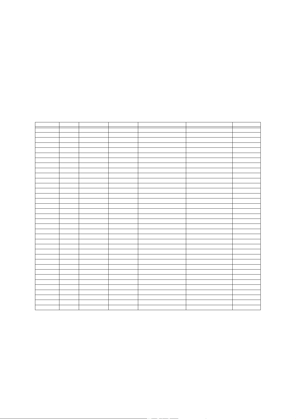
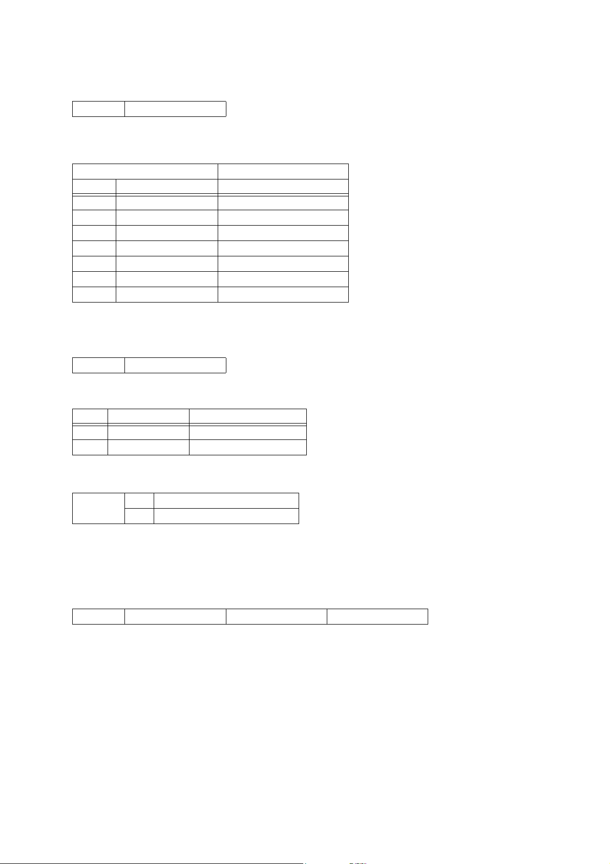
1.2.2 Sound Generator Parts
The settings of the sound generator parts can be changed using Instrument-specific system exclusive messages.
This Instrument consists of 36 parts. Of these, channel messages can be used to perform note on operations and to change
settings of only the C Group (C01 through C16).
The relationships between the channel message receive channel and part number are fixed, as shown below.
Group A parts A01 through A04 are referred to as “zones”. See the Instruments User’s Guide for details about zones.
Part Number Part Name MIDI Receive Ch MIDI Send Ch Assigned Function DSP Priority (Note 2) Description
00 A01 – 01-16(Note1) Keyboard (Main) 1 Upper1
01 A02 – 01-16(Note1) Keyboard (Layer) 3 Upper2
02 A03 – 01-16(Note1) Keyboard (Split) 2 Lower1
03 A04 – 01-16(Note1) Keyboard (Layer Split) 4 Lower2
16 B01 – 01 MIDI file playback 5 Song01
17 B02 – 02 MIDI file playback 5 Song02
18 B03 – 03 MIDI file playback 5 Song03
19 B04 – 04 MIDI file playback 5 Song04
20 B05 – 05 MIDI file playback 5 Song05
21 B06 – 06 MIDI file playback 5 Song06
22 B07 – 07 MIDI file playback 5 Song07
23 B08 – 08 MIDI file playback 5 Song08
24 B09 – 09 MIDI file playback 5 Song09
25 B10 – 10 MIDI file playback 5 Song10
26 B11 – 11 MIDI file playback 5 Song11
27 B12 – 12 MIDI file playback 5 Song12
28 B13 – 13 MIDI file playback 5 Song13
29 B14 – 14 MIDI file playback 5 Song14
30 B15 – 15 MIDI file playback 5 Song15
31 B16 – 16 MIDI file playback 5 Song16
32 C01 01 – MIDI IN 5 Ext.01
33 C02 02 – MIDI IN 5 Ext.02
34 C03 03 – MIDI IN 5 Ext.03
35 C04 04 – MIDI IN 5 Ext.04
36 C05 05 – MIDI IN 5 Ext.05
37 C06 06 – MIDI IN 5 Ext.06
38 C07 07 – MIDI IN 5 Ext.07
39 C08 08 – MIDI IN 5 Ext.08
40 C09 09 – MIDI IN 5 Ext.09
41 C10 10 – MIDI IN 5 Ext.10
42 C11 11 – MIDI IN 5 Ext.11
43 C12 12 – MIDI IN 5 Ext.12
44 C13 13 – MIDI IN 5 Ext.13
45 C14 14 – MIDI IN 5 Ext.14
46 C15 15 – MIDI IN 5 Ext.15
47 C16 16 – MIDI IN 5 Ext.16
Can be changed by zone editing.
This is the DSP line assignment priority. A smaller value indicates a higher priority. For details, see “11.2.1 DSP Line
Structure and Assignment”.
7

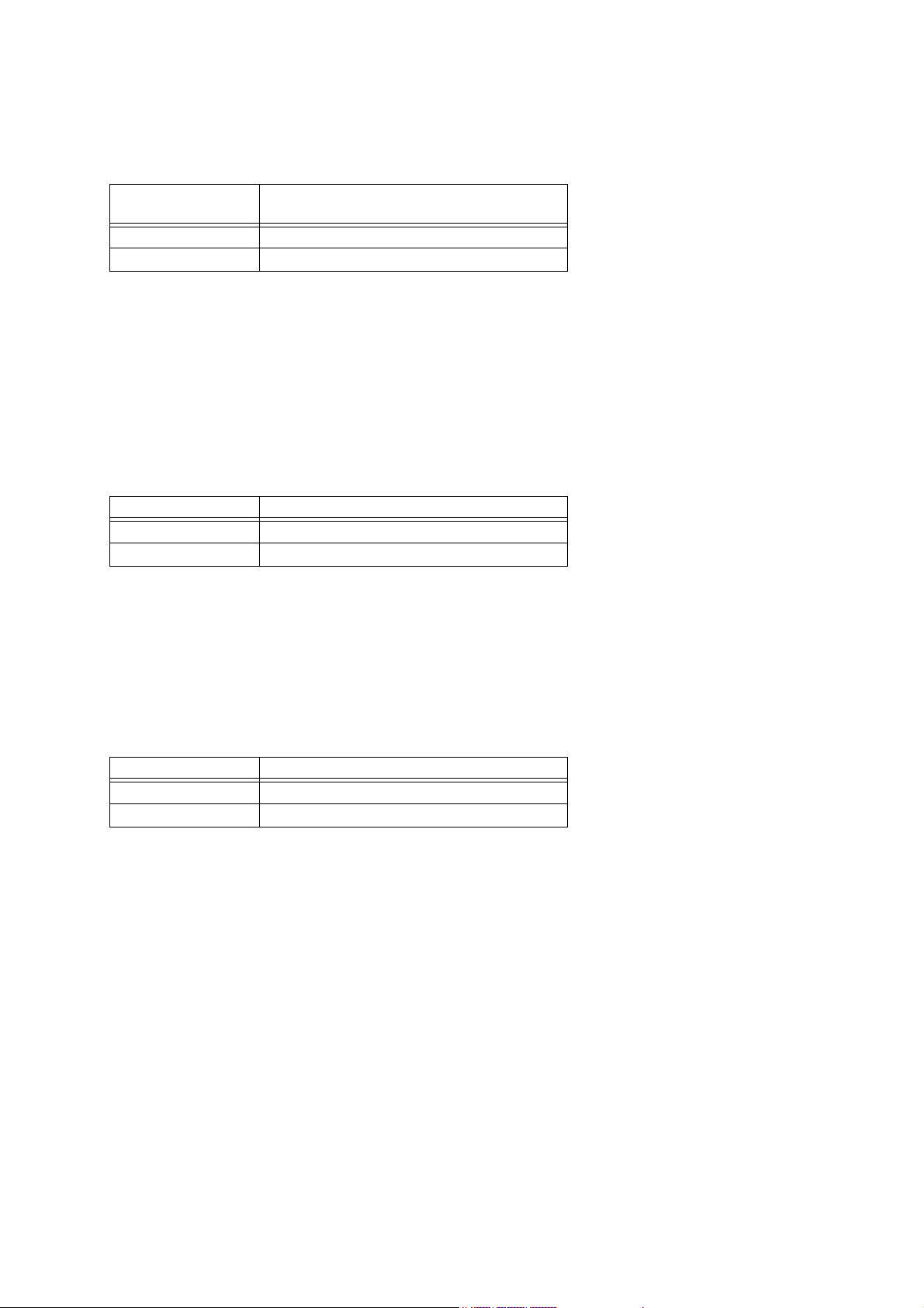
1.2.3 MIDI Receive and Registration
Note 1:
The registration (setup) can be switched by MIDI message. For details about messages, see “19.1 Panel Parameter”.
When switching the registration by MIDI message, the parts reflected by the zone parameters are determined in accordance
with the MIDI send channel setting values of the zone parameters.
The following describes an example of how this works.
Registration Settings (MIDI Send Ch) Part Setting After MIDI Receive (Note 1)
01 Zone1(3) –
02 Zone2(4) –
03 Zone3(14) Zone1
04 Zone4(8) Zone2
05 – –
06 – –
07 – –
08 – Zone4
09 – –
10 – –
11 – –
12 – –
13 – –
14 – Zone3
15 – –
16 – –
Zone parameters are reflected by Group B parts during playback of MIDI files by this Instrument, and by Group C parts
during MIDI receipt from an external device.
Common parameters are not affected. Use this Instrument’s registration function to change common parameters.
Also note that Group A parts are given priority for DSP line assignment. If Group A parts use up all the DSP lines, the
DSP settings of part reflected by the zones are ignored.
For details about DSP line assignments, see “11.2.1 DSP Line Structure and Assignment”.
1.3 Performance Controller Section
The Performance Controller Section consists of keyboard, pedal, and other real-time controllers, as well as blocks that
generate auto performance and other performance information.
These messages are transmitted to the sound generator in accordance with operations, while they are also being sent out
as MIDI messages.
The channel number of the sent message is in accordance with part settings, etc.
1.3.1 Auto Performance MIDI Send
This document covers what operations are sent by messages for each message type. However, since there is wide variation
in the messages that can be sent during an auto performance operation, messages are not covered here.
1.3.2 MIDI Send by Registration
The final MIDI messages sent during a registration operation are system exclusive messages that are specific to this
Instrument, which can switch the registration during MIDI receipt.
For details about messages, see “19.1 Panel Parameter”.
Also, messages that can be sent during a registration operation are so diverse and wide-ranging, messages are not covered
in detail here.
8

1.3.3 MIDI Send by Assignable Buttons
The message(s) sent when an assignable button is pressed depends on the function assigned to the button. Also, any control
change message can be assigned to an assignable button. Since messages that can be sent by an assignable button operation
are so diverse and wide-ranging, messages are not covered in detail here.
2 Conditions that Disable Message Send and Receive
All MIDI message send and receive is temporarily disabled in all of the following cases.
• During Instrument startup
• During SD card formatting
• During storage of registration data
• While “STORAGE” is selected as the “USB DEVICE MODE”.
3 Timbre Type Specific Operation
The operation that is performed for a received message depends on the current Timbre Type setting (see “11.1 About Timbre
Type”), which is the operation mode of each sound generator part. Applicable information is provided in the explanations
for each message.
9
Part II
Send
Receive
Channel Message
4 Send Channel
For information about the MIDI channels of the channel messages that are sent when this Instrument is played, see
“1.2.2 Sound Generator Parts”. Note, however, that the MIDI channel of the performance information that corresponds to
the keyboard main part can be changed by zone editing.
5 Receive Channel
For information about the MIDI channel numbers of channel messages received by each part, see “1.2.2 Sound Generator
Parts”.
The MIDI channel number of a channel message that changes DSP settings also coincides with the MIDI channel of the
part using the DSP. A channel message is not received by a part that is turned off by the Part Enable Parameter value
explained under “20.7 Part Parameters”.
6 Note Off
Format
Send Receive
Message Format:
8nH kkH vvH 8nH kkH vvH
9nH kkH 00H
n: MIDI Channel Number
kk: Key Number
vv: 40H Ignored
Sent when a key is released.
Recognized as key release information. The velocity value is ignored.
10
7Note On
Send
Receive
Send
Receive
Send
Receive
Format
Message Format: 9nH kkH vvH
n: MIDI Channel Number
kk: Key Number
vv: Velocity
Sent when a key is pressed.
Recognized as key press information.
8 Polyphonic Key Pressure
Format
Message Format: AnH kkH vvH
n: MIDI Channel Number
kk: Key Number
vv: Pressure Value
This message is not sent by this Instrument.
This message is not received by this Instrument.
9 Control Change
Format
Message Format: BnH ccH vvH
n: MIDI Channel Number
cc: Control Number
vv: Value
Sent when a pedal or another controller operation is performed, when settings are changed, when the tone is changed, or
when an auto performance, or other operation is performed.
Receipt changes the controller and settings that correspond to the control number.
11
9.1 Bank Select (00H, 20H)
Send
Receive
Send
Receive
Send
Receive
Format
Message Format: BnH 00H mmH (MSB)
BnH 20H llH (LSB)
n: MIDI Channel Number
mm: Value
ll: Value
Sent in the following cases.
• When a tone selection is made
• When a program change message is specified by a zone edit operation
For information about numbers, see the Tone List in the User’s Guide.
Receipt switches the tone bank number stored in Instrument memory. Note, however, that the tone is not changed until a
Program Change message is received.
For details, see “11 Program Change”.
For information about numbers, see the Tone List in the User’s Guide.
9.2 Modulation (01H)
Format
Message Format: BnH 01H vvH
n: MIDI Channel Number
vv: Value
See “1.3.3 MIDI Send by Assignable Buttons”.
Receipt adds, to the voice being sounded, modulation of a depth specified by the value. In the case of a tone that already
has modulation applied, receipt of this message increases the modulation depth. The modulation effect differs according
to the tone being used.
9.3 Portamento Time (05H)
Format
Message Format: BnH 05H vvH
n: MIDI Channel Number
vv: Value
Sent when the portamento time is specified by a zone edit operation.
Receipt changes the time it takes until pitch reaches the target portamento effect pitch.
12
9.4 Data Entry (06H, 26H)
Send
Receive
Send
Receive
Note 1:
Send
Receive
Format
Message Format: BnH 06H vvH (MSB)
BnH 26H vvH (LSB)
n: MIDI Channel Number
vv: Value
Sent when there is a change in the parameters assigned to NRPN and RPN.
For details about information assigned to parameters that correspond to NRPN and RPN, see “9.23 NRPN (62H, 63H)”
and “9.24 RPN (64H, 65H)”.
Receipt changes the parameter assigned to RPN. This Instrument does not have a parameter that corresponds to NRPN.
9.5 Volume (07H)
Format
Message Format: BnH 07H vvH
n: MIDI Channel Number
vv: Value
Sent when the volume level is specified by a zone edit operation.
Receipt changes the volume level of the corresponding part. Changes the Volume setting of the Part Parameter.
9.6 Pan (0AH)
Format
Message Format: BnH 0AH vvH
n: MIDI Channel Number
vv: Value (Note1)
For information about the relationship between setting values and send/receive values, see “27.8 Pan Setting Value Table”
in “Part VII Setting Values and Send/Receive Values”.
Sent when pan is specified by a zone edit operation.
Receipt changes the pan setting of the Pan Part Parameter.
13
9.7 Expression (0BH)
Send
Receive
Send
Receive
Note 1:
Format
Message Format: BnH 0BH vvH
n: MIDI Channel Number
vv: Value
See “1.3.3 MIDI Send by Assignable Buttons”.
Receipt changes the part volume level.
How this message differs from Volume (07H)
Though this message is operationally identical to that of “9.5 Volume (07H),” the purposes of the two messages are different.
This message is used, for example, for crescendo/decrescendo, and other forms of expression while playing. “9.5 Volume
(07H)” is normally used when you want to make a fixed change in volume level.
9.8 General Use Controllers 1 through 8 (10H through 13H, 50H through 53H)
These messages are used to control DSP operation.
Format
Message Format: BnH 10H vvH
BnH 11H vvH
BnH 12H vvH
BnH 13H vvH
BnH 50H vvH
BnH 51H vvH
BnH 52H vvH
BnH 53H vvH
n: MIDI Channel Number
vv: Value (Note1)
DSP Parameter7[0]
DSP Parameter7[1]
DSP Parameter7[2]
DSP Parameter7[3]
DSP Parameter7[4]
DSP Parameter7[5]
DSP Parameter7[6]
DSP Parameter7[7]
Sent when a DSP parameter value is specified by a zone edit operation.
Receipt changes the value of DSP Parameter 7 [0 to 7] (7-bit parameter) assigned to the part specified by the MIDI Channel
Number. For details about parameters, see “21.3 DSP Parameters”.
Any message received that corresponds to the parameter of a number not being used by the currently selected DSP is ignored.
Received values and parameter setting values
The range of the value of each DSP Parameter 7 array element depends on the selected DSP or array number.
Unlike manipulation of a DSP parameter using a System Exclusive Message, a value received by this control change message
is always in the range of 0 to 127, but the range is changed in accordance with the setting range of the applicable parameter
setting. Because of this, it is impossible for a value to be outside of the range.
Conversion to the parameter setting value from the value received with the message can be represented in general terms
by the expression shown below.
Parameter
Setting Value=Parameter
Minimum Value+(
Parameter
Maximum Value-Parameter
Minimum Value)
Received Value
X
127
For details about Parameter 7 of each DSP, see the explanations under “VI DSP Parameter List”.
14
9.9 Hold1 (40H)
Send
Receive
Note 1:
Send
Receive
Format
Message Format: BnH 40H vvH
n: MIDI Channel Number
vv: Value
Sent in the following cases.
• When a pedal that has a sustain (damper) function is operated
• Sent when a MIDI channel is specified by a zone edit operation.
Receipt performs an operation equivalent to a sustain (damper) pedal operation.
Timbre Type Specific Operation
This operation differs in accordance with the Timbre Type (see “11.1 About Timber Type”) setting.
• Timbre Type: Melody
Sustain off/on control is performed in accordance with the value of the received message. For information about
the relationship between setting values and send/receive values, see the “27.1 Off/On Setting Value Table” in
“Part VII Setting Values and Send/Receive Values”.
• Timbre Type: Piano or LM Piano
Continuous control of the following is performed in accordance with the value of the received message.
– Piano note decay rate
– Resonance characteristics and decay rate of Acoustic Resonance effect resonance note
• Timbre Type: Drum
The received message does not affect sound source operation.
9.10 Portamento Switch (41H)
Format
Message Format: BnH 41H vvH
n: MIDI Channel Number
vv: Value (Note1)
For information about the relationship between setting values and send/receive values, see the “27.1 Off/On Setting Value
Table” in “Part VII Setting Values and Send/Receive Values”.
Sent when the portamento on/off setting is specified by a zone edit operation.
Receipt switches portamento between enabled (On) and disabled (Off).
Range of Pitch Change
The range of pitch change for this Instrument’s portamento function is limited. With some tones or keys, portamento may
not be able to drop down to the note assigned to the keys being played.
15
9.11 Sostenuto (42H)
Note 1:
Send
Receive
Note 1:
Send
Receive
Format
Message Format: BnH 42H vvH
n: MIDI Channel Number
vv: Value (Note1)
For information about the relationship between setting values and send/receive values, see the “27.1 Off/On Setting Value
Table” in “Part VII Setting Values and Send/Receive Values”.
Sent in the following cases.
• When a pedal assigned the sostenuto function is operated
• When a MIDI channel is specified by a zone edit operation
Receipt performs an operation equivalent to a sostenuto pedal operation.
9.12 Soft (43H)
Format
Message Format: BnH 43H vvH
n: MIDI Channel Number
vv: Value (Note1)
For information about the relationship between setting values and send/receive values, see the “27.1 Off/On Setting Value
Table” in “Part VII Setting Values and Send/Receive Values”.
Sent in the following cases.
• When a pedal assigned the soft function is operated
• When a MIDI channel is specified by a zone edit operation
Receipt performs an operation equivalent to a soft pedal operation.
16

9.13 Filter Resonance (47H)
Note 1:
Send
Receive
Note 1:
Send
Receive
Note 1:
Send
Receive
Format
Message Format: BnH 47H vvH
n: MIDI Channel Number
vv: Value (Note1)
For information about the relationship between setting values and send/receive values, see “27.6 –64 - 0 - +63 Setting
Value Table” in “Part VII Setting Values and Send/Receive Values”.
See “1.3.3 MIDI Send by Assignable Buttons”.
Receipt changes the strength of filter resonance.
9.14 Release Time (48H)
Format
Message Format: BnH 48H vvH
n: MIDI Channel Number
vv: Value (Note1)
For information about the relationship between setting values and send/receive values, see “27.6 –64 - 0 - +63 Setting
Value Table” in “Part VII Setting Values and Send/Receive Values”.
Sent when the release time is specified by a zone edit operation.
Receipt makes a relative change in the time it takes for a note to decay to zero after a key is released.
9.15 Attack Time (49H)
Format
Message Format: BnH 49H vvH
n: MIDI Channel Number
vv: Value (Note1)
For information about the relationship between setting values and send/receive values, see “27.6 –64 - 0 - +63 Setting
Value Table” in “Part VII Setting Values and Send/Receive Values”.
Sent when the attack time is specified by a zone edit operation.
Receipt makes a relative change in the time it takes for a note to rise to its maximum level.
17
9.16 Filter Cut Off (4AH)
Note 1:
Send
Receive
Note 1:
Send
Receive
Note 1:
Send
Receive
Format
Message Format: BnH 4AH vvH
n: MIDI Channel Number
vv: Value (Note1)
For information about the relationship between setting values and send/receive values, see “27.6 –64 - 0 - +63 Setting
Value Table” in “Part VII Setting Values and Send/Receive Values”.
Sent when filter is specified by a zone edit operation.
Receipt changes how the cut-off filter is applied.
9.17 Vibrato Rate (4CH)
Format
Message Format: BnH 4CH vvH
n: MIDI Channel Number
vv: Value (Note1)
For information about the relationship between setting values and send/receive values, see “27.6 –64 - 0 - +63 Setting
Value Table” in “Part VII Setting Values and Send/Receive Values”.
Sent when the vibrato rate is specified by a zone edit operation.
Receipt changes Vib Rate of the LFO Parameter.
9.18 Vibrato Depth (4DH)
Format
Message Format: BnH 4DH vvH
n: MIDI Channel Number
vv: Value (Note1)
For information about the relationship between setting values and send/receive values, see “27.6 –64 - 0 - +63 Setting
Value Table” in “Part VII Setting Values and Send/Receive Values”.
Sent when the vibrato depth is specified by a zone edit operation.
Receipt changes Vib Auto Depth of the LFO Parameter.
18

9.19 Vibrato Delay (4EH)
Note 1:
Send
Receive
Send
Receive
Send
Receive
Format
Message Format: BnH 4EH vvH
n: MIDI Channel Number
vv: Value (Note1)
For information about the relationship between setting values and send/receive values, see “27.6 –64 - 0 - +63 Setting
Value Table” in “Part VII Setting Values and Send/Receive Values”.
Sent when the vibrato delay is specified by a zone edit operation.
Receipt changes Vib Auto Delay of the LFO Parameter.
9.20 Portamento Control (54H)
Format
Message Format: BnH 54H vvH
n: MIDI Channel Number
kk: Source Note Number
See “1.3.3 MIDI Send by Assignable Buttons”.
Receipt of this message first stores the Source Note Number for the next note. When the next Note On is received, the
portamento effect is applied to the note using this Source Note Number as the pitch start point and the Note On event key
number as the end point. If there already is a note being sounded by Source Note Number at this time, the new note on
is not performed and the portamento effect is applied to the pitch of the note being sounded. That is to say that legato
play is performed.
9.21 Reverb Send (5BH)
Format
Message Format: BnH 5BH vvH
n: MIDI Channel Number
vv: Value
Sent when reverb send is specified by a zone edit operation.
Receipt changes the Rev Send Part Parameter.
19
9.22 Chorus Send (5DH)
Send
Receive
Send
Receive
Format
Message Format: BnH 5DH vvH
n: MIDI Channel Number
vv: Value
Sent when the portamento on/off setting is specified by a zone edit operation.
Receipt changes the Cho Send Part Parameter.
9.23 NRPN (62H, 63H)
Format
Message Format: BnH 62H vvH (LSB)
BnH 63H vvH (MSB)
n: MIDI Channel Number
vv: Value
This message is not sent by this Instrument.
This message is not received by this Instrument.
9.23.1 Functions Assigned to NRPN
This Instrument does not assign any parameters to NRPN.
9.24 RPN (64H, 65H)
Format
Message Format: BnH 64H vvH (LSB)
BnH 65H vvH (MSB)
n: MIDI Channel Number
vv: Value
The following are the parameters assigned to RPN by this Instrument.
20
9.24.1 Pitch Bend Sensitivity
Send
Receive
Send
Receive
Send
Receive
Format
Message Format: BnH 64H 00H 65H 00H 06H mmH 26H llH
n: MIDI Channel Number
mm:
Value 0 - 24
ll:
Send: 00H, Receive: Ignored
Sent when the pitch bend range is changed.
Receipt changes Pitch Bend Sensitivity.
9.24.2 Fine Tune
Format
Message Format: BnH 64H 01H 65H 00H 06H mmH 26H llH
n: MIDI Channel Number
mm: Value MSB
ll: Value LSB
Sent when fine tuning is specified by a zone edit operation.
Receipt changes the Fine Tune Part Parameter.
9.24.3 Coarse Tune
Format
Message Format: BnH 64H 02H 65H 00H 06H mmH 26H 00H
n: MIDI Channel Number
mm: Value
Sent when coarse tuning is specified by a zone edit operation.
Receipt changes the Coarse Tune Part Parameter.
21
9.24.4 Modulation Depth
Send
Receive
Send
Receive
Send
Receive
Send
Receive
Format
Message Format: BnH 64H 05H 65H 00H 06H mmH 26H 00H
n: MIDI Channel Number
mm: Value
This message is not sent by this Instrument.
Receipt changes Vib Mod Depth of the LFO Parameter.
9.24.5 Null
Format
Message Format: BnH 64H 7FH 65H 7F
n: MIDI Channel Number
This message is not sent by this Instrument.
Receipt deselects RPN.
10 Mode Messages
10.1 All Sound Off (78H)
Format
Message Format: BnH 78H 00H
n: MIDI Channel Number
Sent when an SD card is inserted or removed, and when an SD card operation is performed.
Receipt stops all voices that are sounding.
10.2 Reset All Controllers (79H)
Format
Message Format: BnH 79H 00H
n: MIDI Channel Number
This message is not sent by this Instrument.
Receipt initializes each performance controller.
22

10.3 All Notes Off (7BH)
Send
Receive
Send
Receive
Send
Receive
Send
Receive
Format
Message Format: BnH 7BH 00H
n: MIDI Channel Number
Sent when a MIDI channel is specified by a zone edit operation.
Receipt of this message releases the currently sounding voice (same as releasing the keyboard key).
10.4 Omni Off (7CH)
Format
Message Format: BnH 7CH 00H
n: MIDI Channel Number
This message is not sent by this Instrument.
Receipt of this message releases the currently sounding voice (same as releasing the keyboard key).
10.5 Omni On (7DH)
Format
Message Format: BnH 7DH 00H
n: MIDI Channel Number
This message is not sent by this Instrument.
Receipt of this message releases the currently sounding voice (same as releasing the keyboard key).
10.6 Mono (7EH)
Format
Message Format: BnH 7EH 00H
n: MIDI Channel Number
This message is not sent by this Instrument.
Receipt of this message stops the currently sounding voice.
23

10.7 Poly (7FH)
Send
Receive
Send
Receive
Format
Message Format: BnH 7FH 00H
n: MIDI Channel Number
This message is not sent by this Instrument.
Receipt of this message stops the currently sounding voice.
11 Program Change
Format
Message Format: CnH ppH
n: MIDI Channel Number
pp: Program Number
Sent in the following cases.
• When a tone selection is made
• When a program change message is specified by a zone edit operation
For information about numbers, see the Tone List in the User’s Guide.
Receipt changes the tone.
Tone selection is determined by the program value of this message and the Bank Select message value received prior to
this message.
For information about the program number of the actually selected tone, see the Tone List in the User’s Guide.
Also note that receipt of this message may also change the Timbre Type parameter at the same time. For more information,
see “11.1 About Timbre Type” below.
11.1 About Timbre Type
The tone selected by each part of this Instrument has a “Timbre Type” parameter that specifies the type of sound source
for the tone. As explained under “21.1 Basic Parameters”, there are four Timbre Types settings: Melody, LM Piano, Piano,
and Drum. The operation for a received channel message differs according to the Timbre Type.
• Timbre Type: Melody
This Timbre Type is for normal melody tones. The damper pedal performs on/off operations.
• Timbre Type: Piano or LM (Linear Morphing) Piano
This Timbre Type is for piano tones. The decay rate of the voice being sounded and Acoustic Resonance effect
characteristics are continually altered in accordance with the damper pedal position. The method for producing sound
in response to the note messages also is different from that of the melody Timbre Type, and operation is optimized
for piano.
• Timbre Type: Drum
This Timbre Type is for drum sounds. The method for producing sound is optimized for drums. The damper pedal
and sostenuto pedal do not work for sounds that do not recognize Note Off. The tuning setting also does not affect
this Timbre Type.
24

11.2 About DSP
Send
Receive
Send
Receive
11.2.1 DSP Line Structure and Assignment
This Instrument has two DSP lines that can be used simultaneously.
Selecting multiple tones with DSP at the same time creates the possibility that there will not be enough DSP lines. If this
happens, DSP lines will be assigned in accordance with the DSP line assignment priority specified for each part.
When two or more parts have the same priority, the assignment that was made last is given priority.
For details about DSP line assignment priority, see the table under “1.2.2 Sound Generator Parts”.
12 Channel Aftertouch
Format
Message Format: DnH vvH
n: MIDI Channel Number
vv: Value
This message is not sent by this Instrument.
Receipt of this message adds modulation to the voice that is sounding.
The modulation effect differs according to the tone being used.
13 Pitch Bend Change
Format
Message Format: EnH llH mmH
n: MIDI Channel Number
ll: Value LSB
mm: Value MSB
Sent in the following cases.
• When the bend wheel is operated
• When a MIDI channel is specified by a zone edit operation
Receipt of this message changes the pitch of the currently sounding voice. Pitch bend change sensitivity depends on the
setting configured with “9.24.1 Pitch Bend Sensitivity”.
25

Part III
Send
Receive
Send
Receive
System Messages
14 Active Sensing
Format
Message Format: FEH
This message is not sent by this Instrument.
Once this message is received, the Active Sensing mode is entered. If no MIDI message is received for a specified amount
of time, voices being sounded by this Instrument’s sound source are released, the controller is reset, and the Active Sensing
mode is exited.
15 System Exclusive Message
Format
Message Format: F0H....F7H
This Instrument sends and receives standard universal system exclusive messages, and system exclusive messages that have
Instrument-specific formats.
15.1 Universal Realtime System Exclusive Message
Format
Message Format: F0H 7FH....F7H
15.1.1 Master Volume
Format
Message Format: F0H 7FH 7FH 04H 01H llH mmH F7H
ll: Value LSB
mm: Value MSB
This message is not sent by this Instrument.
Receipt changes the Master Volume parameter. Note that the Master Volume parameter cannot be changed with an Instrument
operation.
26

15.1.2 Master Balance
Note 1:
Send
Receive
Note 1:
Send
Receive
Send
Receive
Format
Message Format: F0H 7FH 7FH 04H 02H llH mmH F7H
ll: Value LSB (Note1)
mm: Value MSB (Note1)
For information about the relationship between setting values and send/receive values, see “27.8 Pan Setting Value Table”
in “Part VII Setting Values and Send/Receive Values”.
This message is not sent by this Instrument.
Receipt changes the Master Pan parameter. Note that the Master Pan parameter cannot be changed with an Instrument
operation.
15.1.3 Master Fine Tuning
Format
Message Format: F0H 7FH 7FH 04H 03H llH mmH F7H
ll: Value LSB (Note1)
mm: Value MSB (Note1)
For information about the relationship between setting values and send/receive values, see “27.7 –100 - 0 - +99 Setting
Value Table” in “Part VII Setting Values and Send/Receive Values”.
This message is sent when the tuning setting is changed.
Receipt changes the Master Fine Tune8 parameter of Patch.
Acoustic Resonance Actions
Acoustic Resonance acoustic characteristics also alter Fine Tune of the strings that simulate resonance in accordance with
the Master Fine Tune8 value. Because of this, receipt of this message may cause the resonance interval to change temporarily.
15.1.4 Master Coarse Tuning
Format
Message Format: F0H 7FH 7FH 04H 04H llH mmH F7H
ll: Send: 00H, Receive: Ignored
mm: Value MSB
This message is not sent by this Instrument.
Receipt changes the Patch Master Coarse Tune parameter.
27

15.1.5 Reverb Parameter
Note 1:
Send
Receive
Send
Receive
Note 1:
Format
Message Format: F0H 7FH 7FH 04H 05H 01H 01H 01H
01H 01H ppH vvH F7H
pp: Parameter
vv: Value
Type Format
Message Format: F0H 7FH 7FH 04H 05H 01H 01H 01H
01H 01H 00H vvH F7H
vv: Value (Note1)
For information about the relationship between setting values and send/receive values, see “27.9 Reverb Type Setting Value
Table” in “Part VII Setting Values and Send/Receive Values”.
This message is sent when the System Reverb Type setting is changed.
Receipt changes the Reverb Type parameter.
Time Format
Message Format: F0H 7FH 7FH 04H 05H 01H 01H 01H
01H 01H 01H vvH F7H
vv: Value
This message is not sent by this Instrument.
Receipt changes the Reverb Time parameter.
15.1.6 Chorus Parameter
Format
Message Format: F0H 7FH 7FH 04H 05H 01H 01H 01H
01H 02H ppH vvH F7H
pp: Parameter
vv: Value
Type Format
Message Format: F0H 7FH 7FH 04H 05H 01H 01H 01H
01H 02H 00H vvH F7H
vv: Value (Note1)
For information about the relationship between setting values and send/receive values, see “27.10 Chorus Type Setting
Value Table” in “Part VII Setting Values and Send/Receive Values”.
28

Send
This message is sent when the System Chorus Type setting is changed.
Receive
Send
Receive
Send
Receive
Send
Receive
Send
Receive
Receipt changes the System Chorus Type parameter.
Rate Format
Message Format: F0H 7FH 7FH 04H 05H 01H 01H 01H
01H 02H 01H vvH F7H
vv: Value
This message is not sent by this Instrument.
Receipt changes the System Chorus Rate parameter.
Depth Format
Message Format: F0H 7FH 7FH 04H 05H 01H 01H 01H
01H 02H 02H vvH F7H
vv: Value
This message is not sent by this Instrument.
Receipt changes the System Chorus Depth parameter.
Feedback Format
Message Format: F0H 7FH 7FH 04H 05H 01H 01H 01H
01H 02H 03H vvH F7H
vv: Value
This message is not sent by this Instrument.
Receipt changes the System Chorus Feedback parameter.
Send To Reverb Format
Message Format: F0H 7FH 7FH 04H 05H 01H 01H 01H
01H 02H 04H vvH F7H
vv: Value
This message is not sent by this Instrument.
Receipt changes the Chorus Send To Reverb parameter.
29

15.1.7 GM System Message
Send
Receive
Send
Receive
Send
Receive
Send
Receive
GM System On Format
1 Message Format: F0H 7EH 7FH 09H 01H F7H
This message is not sent by this Instrument.
Receipt puts the sound source into a GM sound source mode. Also, the Scale Tune Enable setting shown under “20.7 Part
Parameters” for parts C01 through C16 become zero, which disables the temperament (scale) function.
GM System Off Format
Message Format: F0H 7EH 7FH 09H 02H F7H
This message is not sent by this Instrument.
Receipt returns the sound source to its power on default settings.
GM2 System On Format
Message Format: F0H 7EH 7FH 09H 03H F7H
This message is not sent by this Instrument.
Though this Instrument does not support GM2, receipt of the GM2 System On message has the same result as receipt of
the GM System On message.
15.1.8 GS Message
Message Format: F0H 41H ddH 42H 12H 40H 00H 7FH 00H 41H F7H
Note: dd (Device ID) is ignored.
This message is not sent by this Instrument.
Receipt performs the same operation as when the GM System On message is received.
15.2 Instrument-Specific System Exclusive Messages
Format
Message Format: F0H 44H 15H 01H....F7H
Most Instrument parameters and user data, and some operation commands can be controlled using this message.
For more information, see “Part IV Instrument-Specific System Exclusive Messages”.
30

Part IV
Instrument-Specific System Exclusive Messages
16 Format
This section explains the format of the Instrument-specific System Exclusive Messages. See “Part V Parameter List” for
information about what type of data can actually be sent.
16.1 Message Classifications
Basically, the operation that corresponds to Instrument-specific system exclusive messages is parameter data transfer. The
following operations can be performed from an external device using this parameter transfer message.
• Modification of an individual Instrument parameter
• Import of an individual Instrument parameter value
In addition to parameters being used as device setting values, some parameters act as commands when received by this
Instrument and as device status information when sent from this Instrument.
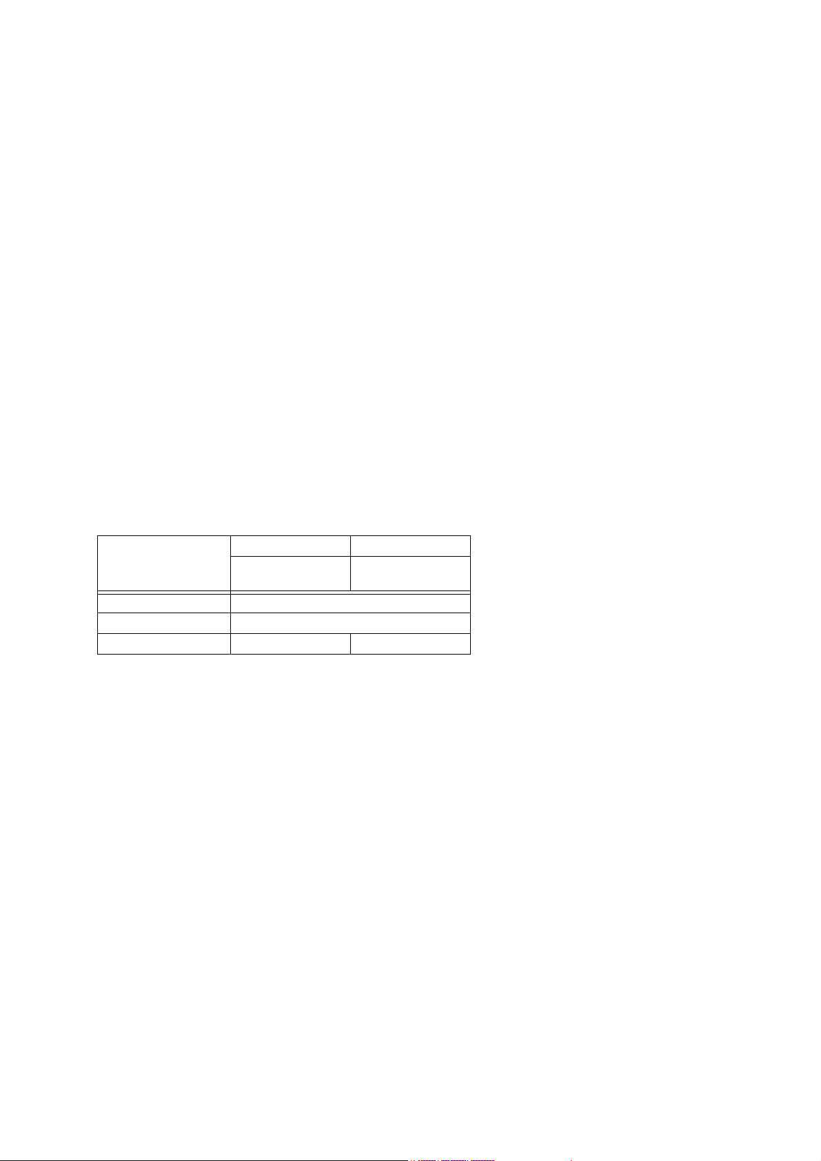
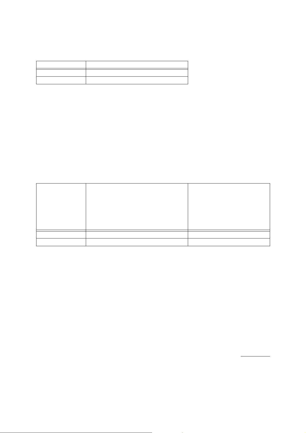
The following table shows the parameter category for each type of transfer.
Function Section Parameter Category Description
System System Commands, Instrument status
Setup Instrument basic settings
Sound Generator Patch Sound source common settings (system effects, master
settings, etc.)
Sound source part settings (tone selection, mixing,
tuning, etc.)
Tone Tone parameter, DSP settings
Scale Tune Scale Tune Table
Registration Registration settings
Registration Bank Registration bank settings
16.2 Basic Message Structure
Since Instrument-specific System Exclusive messages are sent and received on an individual parameter basis, the Individual
Parameter Transfer method is used, and a number of message types are provided to suit specific operations. The field in
the SysEx message that specifies the message type is the action (act) field. The format of the “body” part of the message
depends on the “act” value.
The table below shows the body format for each action of Instrument-specific system exclusive messages. An actual message
consists of the items indicated by “Y”, from left to right.
act SX MAN MOD dev act body (Depends on act.) EOX
cat mem pset blk pkt prm idx len data
IPRYYYYYYYYYYYYY-Y
IPSYYYYYYYYYYYYYYY
31

16.3 Field Formats
16.3.1 SX : System Exclusive Message Status
Format: 11110000B (F0H)
This is the System Exclusive Message status byte established by the MIDI standard.
16.3.2 MAN : Manufacturer’s ID
Format: 01000100B (CASIO = 44H)
Indicates this Instrument’s manufacturer ID.
16.3.3 MOD : Model ID
Format: MSB 00010101B (15H)
LSB 00000010B (02H)
These two successive bytes (MSB, LSB) indicate the PX-130/330/3/730/7/830, AP-220/420/620/6 model ID.
16.3.4 dev : MIDI Device ID 00H - 7FH
Format: 0dddddddB
The contents of this field in a received message are compared with the Model’s MIDI Device ID, and receipt of the incoming
message is allowed only when the two IDs match. The default value for this field is 10H. When a message containing
7FH is received, receipt of the message is always allowed, regardless of this Instrument’s ID setting.
MIDI Device ID is a Patch Parameter, and it can be changed with a System Exclusive Message. In this case, the Device
ID of the MIDI System Exclusive Message must be set to 7FH before it is sent.
16.3.5 act : Action
Format: 0aaaaaaaB
This field indicates the operation of the Instrument-specific System Exclusive Message.
aaaaaaaB Action Function
00H IPR Individual Parameter Request
01H IPS Individual Parameter Send
IPR : Individual Parameter Request
Indicates an individual parameter value send request message. When this Instrument receives this action, it uses an IPS
message to return the specified parameter value.
IPS : Individual Parameter Send
Indicates an individual parameter value send message. When this Instrument receives this action, it rewrites the value specified
by the data field with the specified parameter value.
32
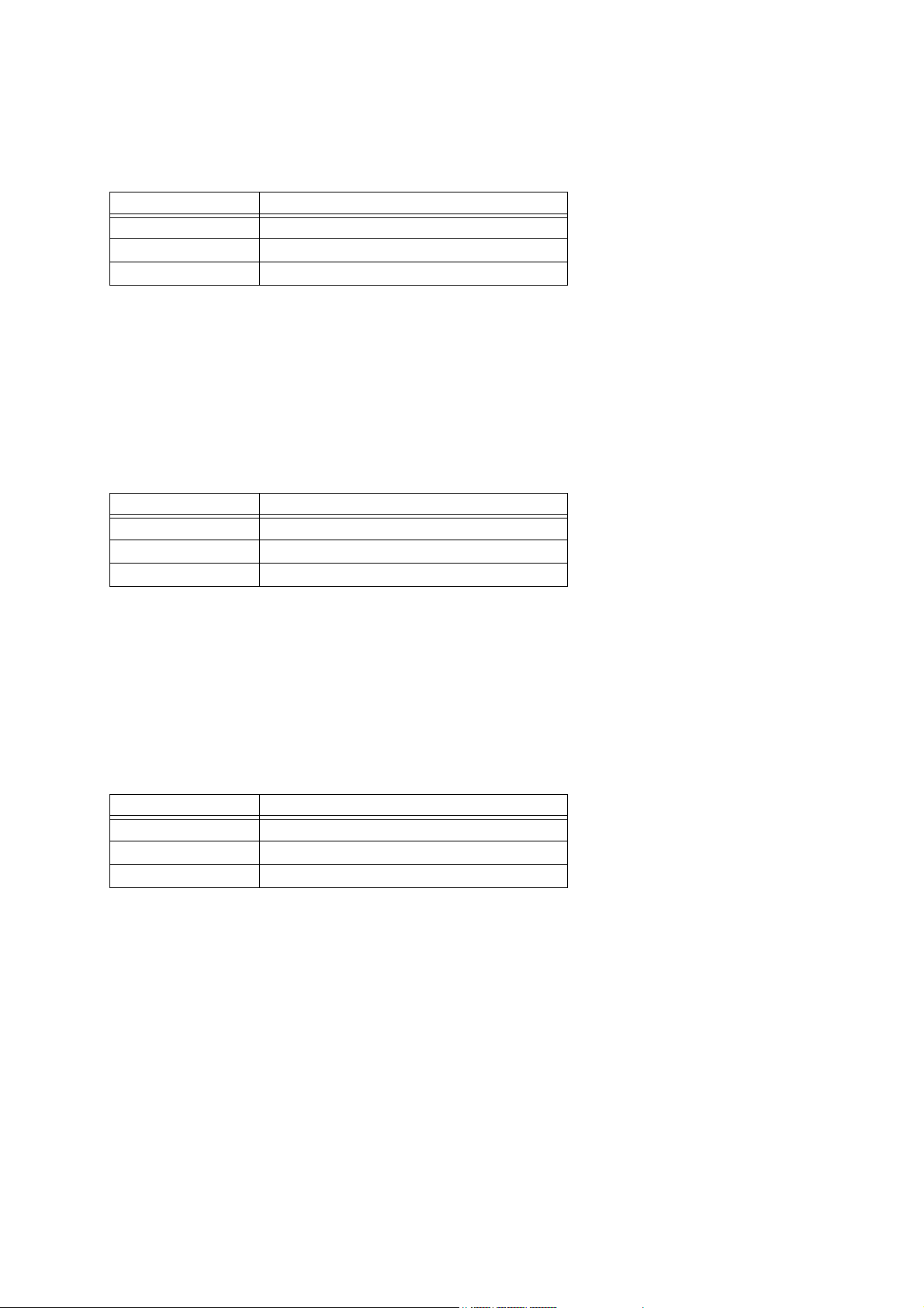
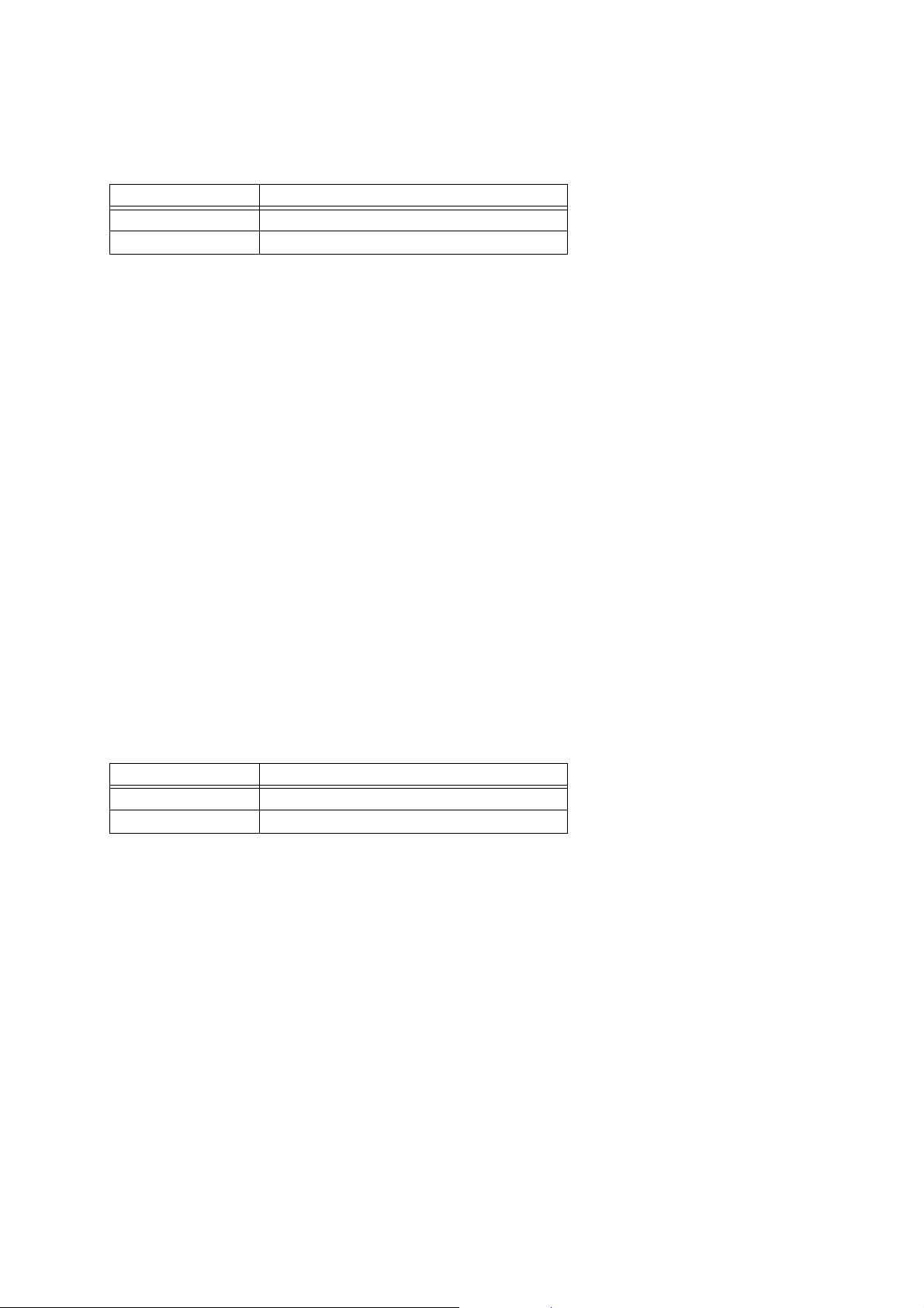
16.3.6 cat : Category
Format: 0cccccccB
0cccccccB = Category (7bit)
The category indicates the categories of data handled by the System Exclusive Message. The ID number (ID) of the category
is indicated on the left, while the communication operation (Action) is indicated on the right.
Category Transfer
ID (c) Parameter Set Individual Parameter
00H System A
01H Setup A
02H Patch A
03H Tone A
12H Scale Tune A
14H Registration A
15H Registration Bank A
A .. Available (Also including when only some parameters are available.)
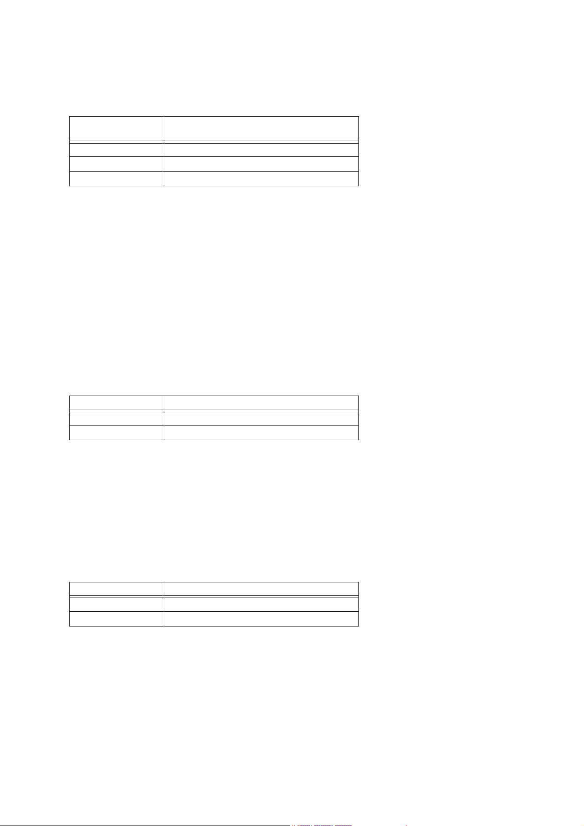
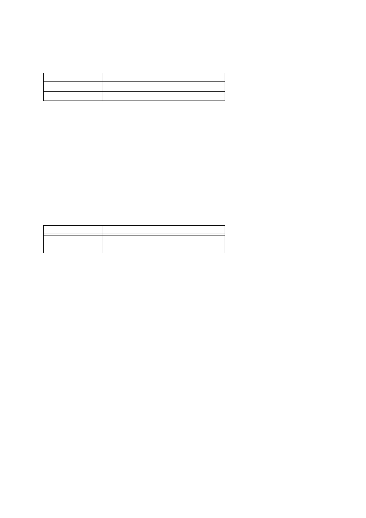
16.3.7 mem : Memory Area ID
Format: 0mmmmmmmB
Specifies the memory area that is the object of the parameter transfer. The following are defined for this Instrument. Basically,
Instrument-specific System Exclusive messages are valid for user area data only.
mem Data Type Meaning
0 User area Read/write enabled
1 Preset area Read/write disabled
16.3.8 pset : Parameter Set Number
Format: LSB 0nnnnnnnB
MSB 0mmmmmmmB
This field is a 2-byte (LSB, MSB) value indicating the number of the parameter set (mmmmmmmnnnnnnnB, binary) being
transferred.
16.3.9 blk : Block Number
This supplementary number specifies which block is the object when there are multiple blocks within the same parameter set.
Format: 0iiiiiiiB (LSB) 0jjjjjjjB 0kkkkkkkB (MSB)
When there are multiple parameters with the same ID inside the same category, as with the mixer channel volume setting
for example, the block number required to specify to which block data belongs is specified as: kkkkkkkjjjjjjjiiiiiiiB (Binary).
When the parameter block has a multi-dimensional array structure, the 21 bits of the block number are divided into prescribed
bit fields based on the rules explained below.
33

Block Bit Field Division
• Case 1
When an array has three or fewer nesting levels and the number of arrays in each dimension is 128 or less, they
are assigned below the three 7-bit fields. Unused regions are filled with zeros.
Example:
parameter [A][B][C]
With a 3-dimensional array parameter that consists of A=8 (3 bits), B=5 (3 bits) and C=10 (4 bits), the block bit
fields are allocated as: Block = 0000aaa 000bbb ccccccc (Binary).
• Case 2
When Case 1 conditions are not satisfied, the minimal number of fields required for each number of arrays is reserved
from the lower bit of the block. Unused regions are filled will zeros.
Example 1:
parameter [A][B][C][D]
With a 4-dimensional array parameter that consists of A=3 (2 bits), B=4 (2 bits), C=3 (2 bits) and D=4 (2 bits)
like the one shown above, the block bit fields are allocated as: Block = 0000000 00000a abbccdd (Binary).
Example 2:
parameter [A][B]
With an A=3 (2 bits), B=200 (8 bits) 2-dimensional array parameter, the block bit fields are allocated as:
Block = 0000000 000aab bbbbbbb (Binary).
16.3.10 prm : Parameter ID
Format: LSB 0pppppppB
MSB 0qqqqqqqB
The Parameter ID indicates the parameter type. (See “Part V Parameter List”.)
When transferring parameters individually (as opposed to bulk transfer), this field is used to identify the parameter by its
parameter ID.
16.3.11 idx : Data Index Number
Format: 0iiiiiiiB
The data index number indicates the first array number of the array where transfer starts.
16.3.12 len : Data Length
Format: 0lllllllB
The value of this field specifies the size of the parameter value stored in the data field. Data length indicates the length
of the array being transferred minus 1 when the parameter contains a character string or other similar array structure.
34

16.3.13 data : Parameter Data
Format: index0 0dddddddB (0eeeeeeeB) (0fffffffB) (0gggggggB) (0hhhhhhhB)
index1 0dddddddB (0eeeeeeeB) (0fffffffB) (0gggggggB) (0hhhhhhhB)
index2 0dddddddB (0eeeeeeeB) (0fffffffB) (0gggggggB) (0hhhhhhhB)
::
indexN 0dddddddB (0eeeeeeeB) (0fffffffB) (0gggggggB) (0hhhhhhhB)
Parameter data indicates the parameter value.
The data array is a list of len + 1 data items.
For a one data item structure, the length depends on the data bit width, as shown below.
dddddB + 1 Number of data
1 - 71
8 - 14 2
15 - 21 3
22 - 28 4
29 - 32 5
Each block of data is packed from the lowest order byte first. In the case of multiple-byte data, the lowest weighted
bit is the least significant digit of the first data byte, and the highest weighted bit is the most significant digit of
the final data byte.
The following shows an example of how data would be divided for transfer in the case of 32-bit data.
76543210
data0: 0 [bit06] [bit05] [bit04] [bit03] [bit02] [bit01] [bit00]
data1: 0 [bit13] [bit12] [bit11] [bit10] [bit09] [bit08] [bit07]
data2: 0 [bit20] [bit19] [bit18] [bit17] [bit16] [bit15] [bit14]
data3: 0 [bit27] [bit26] [bit25] [bit24] [bit23] [bit22] [bit21]
data4: 0 0 0 0 [bit31] [bit30] [bit29] [bit28]
Single Message Size Limit
With this Instrument’s system exclusive message format, the size of a single message cannot exceed 48 bytes.
The data size and the array size, however, can cause a packet to exceed 48 bytes when transferring a single parameter array.
In this case, the IPS and IPR message data length and data index number values can be modified to enable division of a
single parameter value into multiple messages so it can be sent that way.
16.3.14 EOX : End of System Exclusive Message
Format: 11110111B
This is the End of System Exclusive Message status byte established by the MIDI standard.
35

17 Parameter Transfer
There are two parameter operations: Individual Parameter Transfer and Individual Parameter Request.
A single session is concluded only when this Instrument returns an IPS (Individual Parameter Send) in response to an
IPR (Individual Parameter Request) from an external device, or when an external device or this Instrument spontaneously
sends an IPS. If this Instrument received an IPS, the value of the applicable parameter is changed.
Depending on the function of a parameter, Individual Parameter Send may be used to issue a command to this Instrument
or Individual Parameter Request may be used to check Instrument status information.
17.1 Two-way Communication
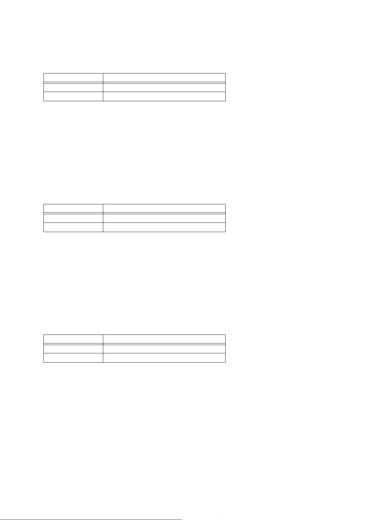
17.1.1 Example : Data send in response to send request to this Instrument
Data Receiver Data Sender Operation
IPR Send Request
IPS Data Transfer
17.2 One-way Communication
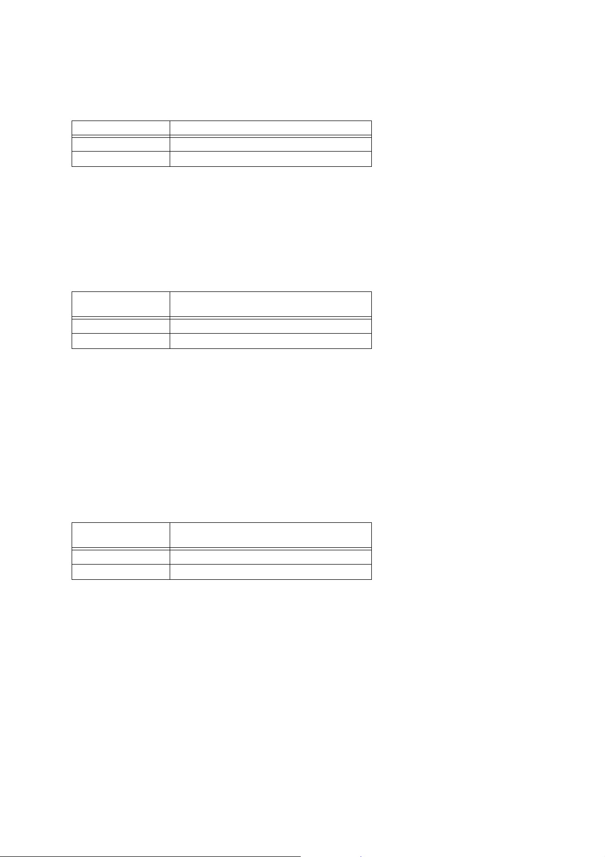
17.2.1 Example : Data send to Instrument from external source
Data Sender Data Receiver Operation
IPS Data Transfer
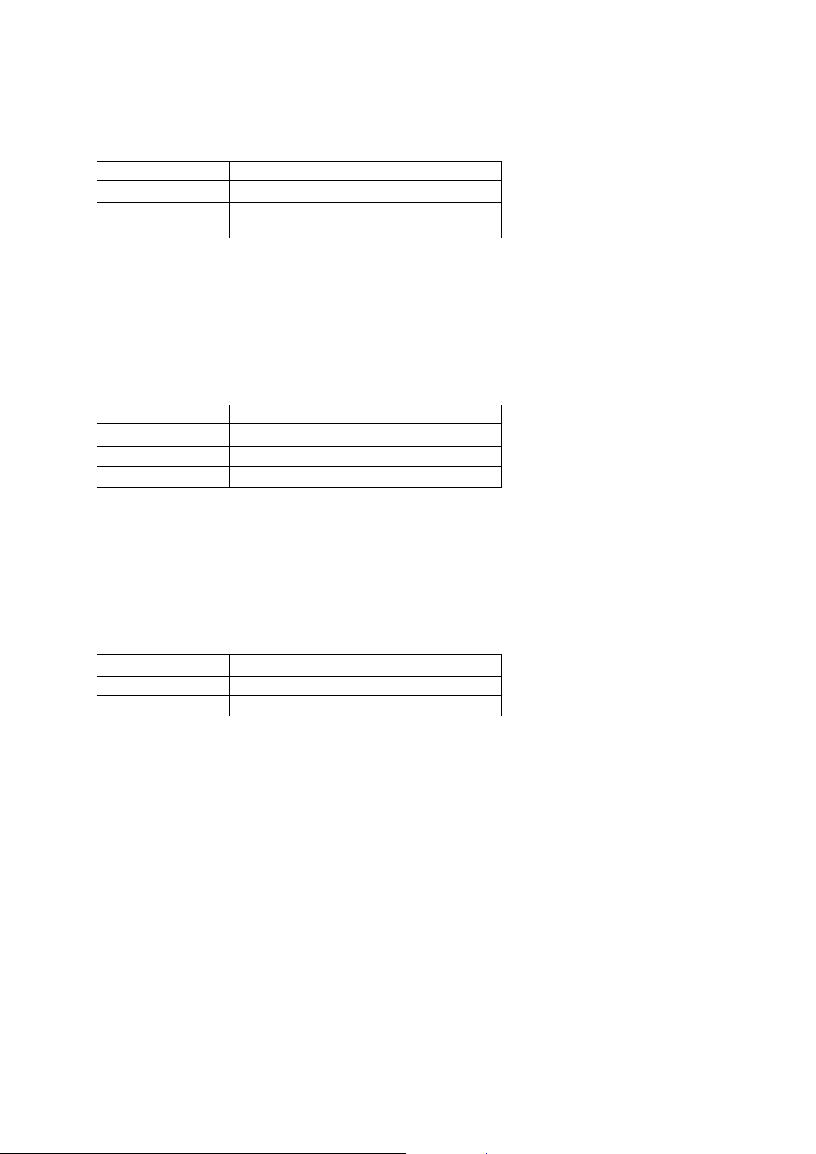
17.2.2 Example : Data send resulting from Instrument operation
Data Receiver Data Sender Operation
IPS Data Transfer
36

Part V
Parameter List
How to Read the Tables
Number Base Notation
“Size” indicates the parameter value bit width as a decimal value.
The bit field position of “Block” as a decimal value.
Values used in the explanations under “Description” are all decimal values, unless specified otherwise.
Values other than those described above are all hexadecimal.
R/W field
The R/W field indicates whether an IPR (Individual Parameter Request) read operation or IPS (Individual Parameter Send)
write operation is enabled.
18 System Parameters
These parameters make it possible for an external device to check the status of this Instrument and for an external device
to command some operation of this Instrument.
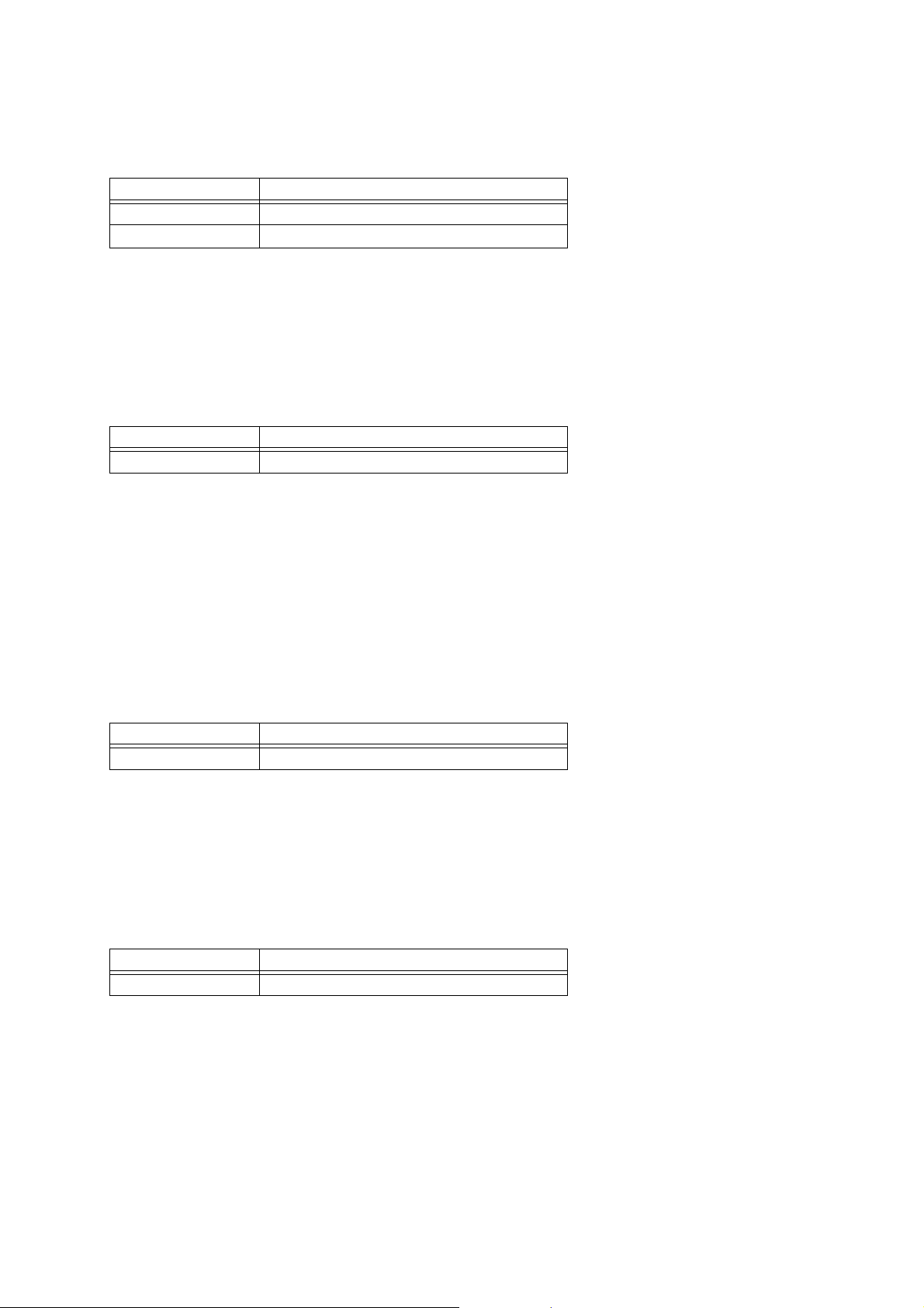
18.1 System Information Parameter
This parameter is a container for system information.
Parameter ID R/W Block Size Array Min-Def-Max Description
Model 0000 R 000000 7 01 00-00-7F 0...PX-130
1...PX-330
2...PX-730/PX-7
3...PX-830
4...reserved
5...AP-220
6...AP-420
7...AP-620/AP-6
8...PX-3
37

19 Setup Parameter
Note 1:
Setup Parameters put a device into the setup mode.
19.1 Panel Parameter
Parameter ID R/W Block Size Array Min-Def-Max Description
Registration
Number For Midi
Operation is not guaranteed for values of 64 (40H) or greater.
19.2 MIDI Parameter
Parameter ID R/W Block Size Array Min-Def-Max Description
Midi Device Id 006D R/W 000000 7 01 00-7F-7F 0-127
0024 R/W 000000 8 01 00-00-FF 0...Bank1 Registration1
1...Bank1 Registration2
:
8...Bank2 Registration1
9...Bank2 Registration2
:
63...Bank8 Registration8
(Note1)
20 Patch Parameters
The main function of patch parameters is to configure the settings of the sound source of a device.
20.1 Master Tune Parameters
These parameters configure the Master Tuning Settings.
Parameter ID R/W Block Size Array Min-Def-Max Description
Master Fine Tune8
Master Coarse Tune
Stretch Tune Enable
20.2 Master Mixer Parameters
These parameters configure the Master settings of the mixer.
Parameter ID R/W Block Size Array Min-Def-Max Description
Master Volume
Master Pan
Acou Reso To Chorus
Acou Reso To Reverb
Acou Reso Return
Chorus To Reverb
Chorus Return
Reverb Return
Dsp Cancel
0001
0002
0003
0012
0013
0016
0018
0019
001D
001E
0025
0028
R/W
R/W
R/W
R/W
R/W
R/W
R/W
R/W
R/W
R/W
R/W
R/W
000000
000000
8
01
7
01
1
01
7
01
7
01
7
01
7
01
7
01
7
01
7
01
7
01
1
01
00-80-FF
00-40-7F
00-01-01
00-7F-7F
00-40-7F
00-00-7F
00-00-7F
00-40-7F
00-00-7F
00-40-7F
00-40-7F
00-00-01
–100 - 0 - +99(cent)
–24 - 0 - +24(semitone)
0...Disable
1...Enable
0-127
–64 - 0 - +63
0-127
0-127
0-127
0-127
0-127
0-127
0...Normal
1...Cancel
38

20.3 System Chorus Parameter
Note 1:
Note 1:
Note 1:
Note 2:
Parameter ID R/W Block Size Array Min-Def-Max Description
Cancel
Type
Rate
Depth
Feedback
Tone
Selects the System Chorus preset type. Receipt of GM/GS Reset selects Chorus3. The value of this type is also linked to
System Chorus parameters, and to the Chorus Send to Reverb and System Chorus Return Level parameters, and its setting
causes these parameters to change to prescribed values. For details about the preset type list, see “27.10 Chorus Type Setting
Value Table”.
0050
0051
0052
0053
0054
0055
R/W
R/W
R/W
R/W
R/W
R/W
000000
1
7
7
7
7
7
01
01
01
01
01
01
00-00-01
00-02-0F
00-0B-7F
00-21-7F
00-00-7F
00-4B-7F
0...Normal
1...Cancel
1-16 (Note1)
0-127
0-127
0-127
0-127
20.4 System Reverb Parameters
Parameter ID R/W Block Size Array Min-Def-Max Description
Cancel
Type
Feedback
Er Level
Damp
Tone
0080
0081
0082
0083
0084
0085
R/W
R/W
R/W
R/W
R/W
R/W
000000
1
7
7
7
7
7
01
01
01
01
01
01
00-00-01
00-04-0F
00-40-7F
00-40-7F
00-67-7F
00-65-7F
0...Normal
1...Cancel
1-16 (Note1)
0-127
0-127
0-127
0-127
Selects the System Reverb preset type. Receipt of GM/GS Reset selects Hall2. This is the value of this Type is also linked
to each of the System Reverb parameters and to the System Reverb Return Level parameter, and changes them to prescribed
values. For details about the preset type list, see “27.9 Reverb Type Setting Value Table”.
20.5 System Acoustic Resonance Parameters
Parameter ID R/W Block Size Array Min-Def-Max Description
0030
R/W
R/W
R/W
R/W
R/W
R/W
R/W
000000
Cancel
Tuning
Damper Pedal
Wet Level Max
Low Boost Freq
Low Boost Level
High Cut Freq
Changing this parameter configures the Tuning setting of System Acoustic Resonance. When this Instrument’s Master Fine
Tune8 setting is changed, this parameter is reset to the Master Fine Tune8 value.
Changing this parameter performs a Damper Pedal operation on System Acoustic Resonance. When the damper pedal of
the part being used by System Acoustic Resonance is operated, this parameter is reset to the depth of the damper pedal
operation.
Note 3:
The value is set when the damper pedal is completely depressed.
0031
0032
003B
003C
003D
003E
1
7
7
16
16
16
16
01
01
01
0000-0800-7FFF
01
0000-0A00-4000
01
0000-7FFF-7FFF
01
0000-2F00-7FFF
01
00-00-01
00-40-7F
00-00-7F
0...Normal
1...Cancel
–100 - 0 - +99(cent) (Note1)
0-127 (Note2)
0x0000-0x7FFF (Note3)
0x0000-0x4000
0x0000-0x7FFF
0x0000-0x7FFF
39

20.6 Master Equalizer Parameter
Note 1:
Note 2:
Parameter ID R/W Block Size Array Min-Def-Max Description
Low Freq
Low Gain
Mid1 Freq
Mid1 Gain
Mid2 Freq
Mid2 Gain
Mid6 Gain
High Freq
High Gain
Selects the Master EQ low-range cutoff frequency. See “27.11 Equalizer Low Frequency Setting Value Table”.
Selects the Master EQ gain. See “27.14 Equalizer Gain Setting Value Table”.
Note 3:
Selects the Master EQ mid frequency. See “27.12 Equalizer Mid Frequency Setting Value Table”.
Note 4:
Selects the Master EQ high-range cutoff frequency. See “27.13 Equalizer High Frequency Setting Value Table”.
00A1
00A2
00A3
00A4
00A5
00A6
00AE
00AF
00B0
R/W
R/W
R/W
R/W
R/W
R/W
R/W
R/W
R/W
000000
7
01
7
01
7
01
7
01
7
01
7
01
7
01
7
01
7
01
00-00-02
00-0C-18
00-04-07
00-0C-18
00-04-07
00-0C-18
00-0C-18
00-02-02
00-0C-18
0-2 (Note1)
-12 - 0 - +12 (Note2)
0-7 (Low-Mid) (Note3)
-12 - 0 - +12 (Low-Mid) (Note2)
0-7 (High-Mid) (Note3)
-12 - 0 - +12 (High-Mid) (Note2)
-12 - 0 - +12 (Brilliance) (Note2)
0-2 (Note4)
-12 - 0
- +12 (Note2)
20.7 Part Parameters
Parameter ID R/W Block Size Array Min-Def-Max Description
Part Enable
Tone Num
Fine Tune
Coarse Tune
Scale Tune Enable
Volume
Acmp Volume
Pan
Cho Send
Rev Send
Acou Reso Send
Bend Range
00E0
00E1
00E2
00E3
00E4
00E5
00E6
00E7
00E8
00E9
00EA
00EC
R/W
5-0: Part #
R/W
R/W
R/W
R/W
R/W
R/W
R/W
R/W
R/W
R/W
R/W
20-6: 0
1
14
7
7
1
7
7
7
7
7
7
7
01
0000-0000-3FFF
01
01
01
01
01
01
01
01
01
01
01
00-01-01
00-40-7F
28-40-58
00-00-01
00-64-7F
00-7F-7F
00-40-7F
00-00-7F
00-28-7F
00-00-7F
00-02-18
0...Off
1...On
0-16383
–100 - 0 - +99(cent)
–24 - 0 - +24(semitone)
0...Disable
1...Enable
0-127
0-127
–64 - 0 - +63
0-127
0-127
0-127
0-24
40

20.8 Part Registration Parameter
Note 1:
Note 2:
Parameters that have the same names as Part Parameters have the same functions as well.
Parameter ID R/W Block Size Array Min-Def-Max Description
Tone Num
Internal External
Select
Volume
Pan
Octave Shift
Midi Channel
Bank Msb
Bank Lsb
Program Change
Dsp Type
Dsp Parameters
Dsp Reverb Send
Dsp Chorus Send
Coarse Tune
Fine Tune
Portamento Onoff
Portamento Time
Attack
Release
Filter
Touch Sense
Vibrato Rate
Vibrato Depth
Vibrato Delay
Vibrato Waveform
Rev Send
Cho Send
Acou Reso Send
Dsp Onoff
Pedal Onoff
Bender Onoff
Assign1 Onoff
Assign2 Onoff
0100
0102
0103
0104
0105
0106
0107
0108
0109
010A
010B
010C
010D
010E
010F
0110
0111
0112
0113
0114
0115
0116
0117
0118
0119
011A
011B
011C
011D
011E
011F
0120
0121
R/W
R/W
R/W
R/W
R/W
R/W
R/W
R/W
R/W
R/W
R/W
R/W
R/W
R/W
R/W
R/W
R/W
R/W
R/W
R/W
R/W
R/W
R/W
R/W
R/W
R/W
R/W
R/W
R/W
R/W
R/W
R/W
R/W
20-6: 0
5-0: Part #
14
0000-0000-3FFF
01
2
01
01
7
01
7
01
7
01
4
01
7
01
7
01
7
01
8
10
7
01
7
01
7
01
7
01
8
01
1
01
7
01
7
01
7
01
7
01
7
01
7
01
7
01
7
01
3
01
7
01
7
01
7
01
1
01
1
01
1
01
1
01
1
00-03-03
00-7F-7F
00-40-7F
3E-40-42
00-00-0F
00-00-7F
00-00-7F
00-00-7F
00-40-40
00-00-7F
00-28-7F
00-00-7F
34-40-4C
1D-80-E3
00-00-01
00-00-7F
00-40-7F
00-40-7F
00-40-7F
00-7F-7F
00-40-7F
00-40-7F
00-40-7F
00-00-07
00-28-7F
00-00-7F
00-00-7F
00-01-01
00-01-01
00-01-01
00-01-01
00-01-01
0-16383
00(0)...Both Off
01(1)...External Only
10(2)...Internal Only
11(3)...Both On (Note1)
0-127
-64 - 0 - +63
-2 - 0 - +2
1-16 (Note1)
0-127
0-127
0-127
0....DSP# 1
:
63...DSP# 64
64...Default DSP of
Tone (Note2)
0-127
0-127
0-127
-12 - 0 - +12
-99 - 0 - +99
0...Off
1...On
0-127
-64 - 0 - +63
-64 - 0 - +63
-64 - 0 - +63
-64 - 0 - +63
-64 - 0 - +63
-64 - 0 -
-64 - 0 - +63
0...Original
1...Sin
2...Tri
3...Saw Up
4...Saw Down
5...Puls 1:3
6...Puls 2:2
7...Puls 3:1
0-127
0-127
0-127
0...Off
1...On
0...Off
1...On
0...Off
1...On
0...Off
1...On
0...Off
1...On
+63
Does not apply to Group C (C01 through C16) parts.
DSP types correspond to DSP numbers. For information about the relationship between DSP numbers and DSP algorithms,
see the Instrument’s User’s Guide. The DSP Type 64 algorithm is the one applied to the current tone, and it is equivalent
to this Instrument’s DSP type “ton” setting (initial default setting for each tone). For information about DSP algorithm
applied to each tone, see the Instrument’s User’s Guide.
41

21 Tone Parameters
Note 1:
21.1 Basic Parameters
Parameter ID R/W Block Size Array Min-Def-Max Description
Name
Timbre Type
Timbre Num
Oct Shift
Line Select
Level
Touch Sens
Sys Fx Send Override
Cho Normal Send
Rev Send
Acou Reso Send
When a tone is selected whose Sys Fx Send Override parameter setting is “Yes”, the send level setting value to the
System Chorus, System Reverb, and System Acoustic Resonance of the part assigned to this tone is rewritten to the value
that is stored by this tone.
0000
0001
0002
0003
0004
0005
0006
0007
0008
000A
000B
R/W
R/W
R/W
R/W
R/W
R/W
R/W
R/W
R/W
R/W
R/W
000000
7
4
14
3
1
7
7
1
7
7
7
10
01
0000-0000-3FFF
01
01
01
01
01
01
01
01
01
00-20-7F
00-00-0F
02-04-06
00-00-01
00-7F-7F
00-7F-7F
00-00-01
00-00-7F
00-28-7F
00-00-7F
Ascii Character
0...Melody
1...Piano
2...Drum
3...reserved
4...LM Piano
0-16383
–2 - 0 - +2
0...Direct
1...DSP
0-127
–64 - 0 - +63
0...No (Note1)
1...Yes
0-127
0-127
0-127
42

21.2 LFO Parameters
Note 1:
Note 1:
Parameter ID R/W Block Size Array Min-Def-Max Description
Vib Wave
Vib Rate
Vib Auto Delay
Vib Auto Rise
Vib Auto Depth
Vib Mod Depth
Vib After Depth
Lfo Wave
Lfo Rate
Lfo Fil Auto Delay
Lfo Fil Auto Rise
Lfo Fil Auto Depth
Lfo Fil Mod Depth
Lfo Fil After Depth
Lfo Amp Auto Delay
Lfo Amp Auto Rise
Lfo Amp Auto Depth
Lfo Amp Mod Depth
Lfo Amp After Depth
000D
000E
000F
0010
0011
0012
0013
0014
0015
0016
0017
0018
0019
001A
001B
001C
001D
001E
001F
R/W
R/W
R/W
R/W
R/W
R/W
R/W
R/W
R/W
R/W
R/W
R/W
R/W
R/W
R/W
R/W
R/W
R/W
R/W
000000
4
01
7
01
7
01
7
01
7
01
7
01
7
01
4
01
7
01
7
01
7
01
7
01
7
01
7
01
7
01
7
01
7
01
7
01
7
01
00-00-0F
00-40-7F
00-40-7F
00-40-7F
00-40-7F
00-40-7F
00-40-7F
00-00-0F
00-40-7F
00-40-7F
00-40-7F
00-40-7F
00-40-7F
00-40-7F
00-40-7F
00-40-7F
00-40-7F
00-40-7F
00-40-7F
0...Sin
1...Tri
2...Saw Up
3...Saw Down
4...Pulse 1:3
5...Pulse 2:2
6...Pulse 3:1
15...Depends on original
–64 - 0 - +63 (Note1)
–64 - 0 - +63 (Note1)
–64 - 0 - +63 (Note1)
–64 - 0 - +63 (Note1)
–64 - 0
–64 - 0 - +63 (Note1)
0...Sin
1...Tri
2...Saw Up
3...Saw Down
4...Pulse 1:3
5...Pulse 2:2
6...Pulse 3:1
15...Depends on original
–64 - 0 - +63 (Note1)
–64 - 0 - +63 (Note1)
–64 - 0 - +63 (Note1)
–64 - 0 - +63 (Note1)
–64 - 0 - +63 (Note1)
–64 - 0 - +63 (Note1)
–64 - 0 - +63 (Note1)
–64 - 0 - +63 (Note1)
–64 - 0 - +63 (Note1)
–64 - 0 - +63 (Note1)
–64 - 0 - +63 (Note1)
- +63 (Note1)
The function of this parameter is to relatively change the original setting value of the tone. The parameter is set to the
maximum value when the maximum is exceeded, and to the minimum when the minimum is exceeded.
21.3 DSP Parameters
Parameter ID R/W Block Size Array Min-Def-Max Description
002D
002E
002F
0031
0032
0034
R/W
R/W
R/W
R/W
R/W
R/W
Name
Algorithm
Cho Normal Send
Rev Send
Acou Reso Send
Parameter7
This value is the DSP algorithm ID, which cannot be changed directly at the user level. Changing the DSP Type or Tone
Number causes the algorithm ID of the original DSP to be copied automatically to this area. See “25 DSP Algorithm ID
Tables”.
000000
7
14
7
7
7
7
10
0000-0000-3FFF
01
01
01
01
20
00-20-7F
00-00-7F
00-28-7F
00-00-7F
00-40-7F
43
Ascii Character
Serial Number
(Note1)
0-127
0-127
0-127
0-127

22 Scale Tune
Parameter ID R/W Block Size Array Min-Def-Max Description
Note
A Key Mode
0000
0001
R/W
R/W
000000
8
0C
1
01
00-80-FF
00-00-01
–128 - 0 - 127
Array : Note
0....C
1....C#
2....D
3....D#
4....E
5....F
6....F#
7....G
8....G#
9....A
10...A#
11...B
0...Relative
1...Absolute
23 Registration Parameter
Registration parameters are this Instrument’s registration setting data.
23.1 Assignable Button 1 Parameter
Parameter ID R/W Block Size Array Min-Def-Max Description
Type
Modulation Depth (Sw Off)
Modulation Depth (Sw Off)
CC Number
CC Channel
CC Value (Sw Off)
CC Value (Sw On)
002D
002E
002F
0030
0031
0032
0033
R/W
R/W
R/W
R/W
R/W
R/W
R/W
000000
2
01
7
01
7
01
7
01
4
01
7
01
7
01
00-00-02
00-00-7F
00-7F-7F
00-00-7F
00-00-0F
00-00-7F
00-00-7F
0...Modulation
1...Portamento
2...Control Change
0-127
0-127
0-127
1-16
0-127
0-127
23.2 Assignable Button 2 Parameter
Parameter ID R/W Block Size Array Min-Def-Max Description
Type
Dsp Bypass Zone
CC Number
CC Channel
CC Value (Sw Off)
CC Value (Sw On)
0034
0035
0036
0037
0038
0039
R/W
R/W
R/W
R/W
R/W
R/W
000000
2
2
7
4
7
7
01
01
01
01
01
01
00-00-03
00-00-03
00-00-7F
00-00-0F
00-00-7F
00-00-7F
0...Rotary
1...Portamento
2...DSP Bypass
3...Control Change
0...Upper1
1...Upper2
2...Lower1
3...Lower2
0-127
1-16
0-127
0-127
44

23.3 Common Parameter
Parameter ID R/W Block Size Array Min-Def-Max Description
Layer Onoff
Split Onoff
Split Point
Reverb Onoff
Reverb Type
Chorus Onoff
Chorus Type
Transpose
Bend Range
Brilliance
Touch Curve
Temperament Type
Temperament Root
Stretch Tune Onoff
Acoustic Resonance Onoff
Half Damper Depth
Pedal Assign
0022
0023
0024
0025
0026
0027
0028
0029
002A
002B
002C
0043
0044
0045
0046
0047
0048
R/W
R/W
R/W
R/W
R/W
R/W
R/W
R/W
R/W
R/W
R/W
R/W
R/W
R/W
R/W
R/W
R/W
000000
1
01
1
01
7
01
1
01
2
01
1
01
2
01
7
01
4
01
7
01
2
01
5
01
01
4
01
1
01
1
01
6
01
2
00-00-01
00-00-01
15-30-6C
00-00-01
00-00-03
00-00-01
00-00-03
34-40-4C
00-02-0C
3D-40-43
00-02-03
00-00-10
00-00-0B
00-01-01
00-01-01
00-18-2A
00-00-01
0...Off
1...On
0...Off
1...On
21....A0
22....Bb0
:
107...B7
108...C8
0...Off
1...On
0...Room
1...Hall
2...Large Hall
3...Stadium
0...Off
1...On
0...Light Chorus
1...Chorus
2...Deep Chorus
3...Flanger
-12 - 0 - +12
0-12
-3 - 0 - +3
Off(0), 1, 2, 3
0-16
0....C
1....C#
2....D
3....D#
4....E
5....F
6....F#
7....G
8....G#
9....A
10...A#
11...B
0...Off
1...On
0...Off
1...On
0-42
0...Soft
1...Sostenuto
45

23.4 Equalizer Parameter
Note 1:
Note 2:
This is a registration parameter whose operation is basically the same as the Master Equalizer Parameter.
Parameter ID R/W Block Size Array Min-Def-Max Description
Equalizer Low Gain
Equalizer Lowmid Gain
Equalizer Highmid Gain
Equalizer High Gain
Equalizer Low Frequency
Equalizer Lowmid Frequency
Equalizer Highmid Frequency
Equalizer High Frequency
Equalizer Onoff
See “27.14 Equalizer Gain Setting Value Table”.
See “27.11 Equalizer Low Frequency Setting Value Table”.
Note 3:
See “27.12 Equalizer Mid Frequency Setting Value Table”.
Note 4:
See “27.13 Equalizer High Frequency Setting Value Table”.
003A
003B
003C
003D
003E
003F
0040
0041
0042
R/W
R/W
R/W
R/W
R/W
R/W
R/W
R/W
R/W
000000
7
01
7
01
7
01
5
01
3
01
3
01
3
01
3
01
1
01
34-40-4C
34-40-4C
34-40-4C
34-40-4C
00-00-02
00-00-07
00-04-07
00-02-02
00-01-01
-12 - 0 - +12 (Note1)
-12 - 0 - +12 (Note1)
-12 - 0 - +12 (Note1)
-12 - 0 - +12 (Note1)
0-2 (Note2)
0-7 (Note3)
0-7 (Note3)
0-2 (Note4)
0...Off
1...On
24 Registration Bank Parameter
24.1 Bank Common
Parameter ID R/W Block Size Array Min-Def-Max Description
Name 0000 R/W 2-0: Bank # 8 0C 00-20-FF Ascii Character
46

Part VI
DSP Parameter List
25 DSP Algorithm ID Tables
The lists in this section show the DSP algorithms that are built into this Instrument.
25.1 Stereo Tone DSP
Number
M01
M02
M03
M04
M05
M06
M07
M08
M09
M10
M11
M12
M13
M14
M15
M16
M17
M18
M19
M20
M21
M22
M23
M24
M25
M26
ID Algorithm Input
01
2001 Equalizer Stereo Stereo
02
2002 Compressor Stereo Stereo
03
2003 Limiter Stereo Stereo
04
2004 Enhancer Stereo Stereo
05
2006 Chorus Stereo Stereo
06
2007 Tremolo Stereo Stereo
07
200B Early Reflection Mix Stereo
08
200C Rotary Mix Stereo
09
200D Drive Rotary Mix Stereo
10
2010 3-Phase Chorus Mix Stereo
11
2011 Auto Pan Stereo Stereo
12
2019 Stereo Phaser Stereo Stereo
13
201A Phaser Mix Stereo
14
201B Distortion Mix Stereo
15
201C Auto Wah Mix Stereo
16
201D LFO Wah Mix Stereo
17
201E Flanger Stereo Stereo
2013 Multi01(Enhancer - Chorus) Mix Stereo
2014 Multi02(Chorus - Tremolo) Mix Stereo
2015 Multi03(Compressor Enhancer) Mix Stereo
2016 Multi04(Compressor - Chorus) Mix Stereo
201F Multi05(Phaser - Chorus) Stereo Stereo
2020 Multi06(Phaser - Auto Pan) Stereo Stereo
2021 Multi07(Chorus - Flanger) Stereo Stereo
2022 Multi08(Auto Wah - Phaser) Mix Stereo
2023 Multi09(Distortion - Phaser) Mix Stereo
2024 Multi10(Distortion - Chorus) Mix Stereo
2025 Multi11(Compressor - Auto Wah) Mix Stereo
2026 Multi12(Compressor - LFO Wah) Mix Stereo
2027 Multi13(Distortion - Auto Pan) Mix Stereo
2028 Multi14(Distortion - Tremolo) Mix Stereo
2029 Multi15(Compressor - Auto Pan) Stereo Stereo
202A Multi16(Compressor - Tremolo) Stereo Stereo
202B Multi17(Compressor - Phaser) Stereo Stereo
202C Multi18(Phaser - Distortion) Mix Stereo
202D Multi19(Phaser - Chorus - Auto) Pan Stereo Stereo
202E Multi20(LFO Wah - Chorus) Mix Stereo
202F Multi21(Auto Wah - Chorus) Mix Stereo
2030 Multi22(Compressor - Distortion - Chorus) Mix Stereo
2031 Multi23(LFO Wah - Distortion - Chorus) Mix Stereo
2032 Multi24(Auto Wah - Distortion - Chorus) Mix Stereo
2033 Multi25(Compressor - Distortion - Auto Pan) Mix Stereo
2034 Multi26(Compressor - Distortion - Tremolo) Mix Stereo
Output
Multi22(Compressor - Distortion - Chorus)
Multi23(LFO Wah - Distortion - Chorus)
Multi24(Auto Wah - Distortion - Chorus)
Multi25(Compressor - Distortion - Auto Pan)
Multi26(Compressor - Distortion - Tremolo)
Parameter Set Type
Equalizer
Compressor
Limiter
Enhancer
Chorus
Tremolo/Auto Pan
Early Reflection
Rotary
Drive Rotary
3-Phase Chorus
Tremolo/Auto Pan
Stereo Phaser/Phaser
Stereo Phaser/Phaser
Distortion
Auto Wah
LFO Wah
Flanger
Multi01(Enhancer - Chorus)
Multi02(Chorus - Tremolo)
Multi03(Compressor Enhancer)
Multi04(Compressor - Chorus)
Multi05(Phaser - Chorus)
Multi06(Phaser - Auto Pan)
Multi07(Chorus - Flanger)
Multi08(Auto Wah - Phaser)
Multi09(Distortion - Phaser)
Multi10(Distortion - Chorus)
Multi11(Compressor - Auto Wah)
Multi12(Compressor - LFO Wah)
Multi13(Distortion - Auto Pan)
Multi14(Distortion - Tremolo)
Multi15(Compressor - Auto Pan)
Multi16(Compressor - Tremolo)
Multi17(Compressor - Phaser)
Multi18(Phaser - Distortion)
Multi19(Phaser - Chorus - Auto)
Multi20(LFO Wah - Chorus)
Multi21(Auto Wah - Chorus)
47

26 DSP Parameter Set Types
This section describes the DSP parameter combination patterns of each algorithm specified in the “Parameter Set Type”
column of “25 DSP Algorithm ID Tables”.
Note:
The characteristics of a DSP are different depending on the tone, even if the same algorithm is used. Because of this, the
same algorithm may not produce the same effect for different tones.
26.1 Equalizer
Parameter Number Parameter Name Value Notes
Parameter7[00] EQ1 Freq 00 - 07 Note1
Parameter7[01] EQ1 Gain 34 - 4C Note2
Parameter7[02] EQ2 Freq 00 - 07 Note1
Parameter7[03] EQ2 Gain 34 - 4C Note2
Parameter7[04] EQ3 Freq 00 - 07 Note1
Parameter7[05] EQ3 Gain 34 - 4C Note2
Note 1: See “27.12 Equalizer Mid Frequency Setting Value Table”.
Note 2: See “27.15 DSP Equalizer Gain Setting Value Table”.
26.2 Compressor
Parameter Number Parameter Name Value Notes
Parameter7[00] Depth 00 - 7F
Parameter7[01] Attack 00 - 7F
Parameter7[02] Release 00 - 7F
Parameter7[03] Level 00 - 7F
26.3 Limiter
Parameter Number Parameter Name Value Notes
Parameter7[00] Limit 00 - 7F
Parameter7[01] Attack 00 - 7F
Parameter7[02] Release 00 - 7F
Parameter7[03] Level 00 - 7F
26.4 Enhancer
Parameter Number Parameter Name Value Notes
Parameter7[00] Low Freq 00 - 7F
Parameter7[01] Low Gain 00 - 7F
Parameter7[02] High Freq 00 - 7F
Parameter7[03] High Gain 00 - 7F
48

26.5 Chorus
Parameter Number Parameter Name Value Notes
Parameter7[00] Rate 00 - 7F
Parameter7[01] Depth 00 - 7F
Parameter7[02] Feedback 00 - 7F Note1
Parameter7[03] Wet Level 00 - 7F
Parameter7[04] Polarity 00 - 7F Note2
Note 1: See “27.6 –64 - 0 +63 Setting Value Table”.
Note 2: See “27.2 –/+ Setting Value Table”.
26.6 Tremolo
Parameter Number Parameter Name Value Notes
Parameter7[00] Rate 00 - 7F
Parameter7[01] Depth 00 - 7F
26.7 Early Reflection
Parameter Number Parameter Name Value Notes
Parameter7[00] Wet Level 00 - 7F
Parameter7[01] Feedback 00 - 7F
Parameter7[02] Tone 00 - 7F
26.8 Rotary
Parameter Number Parameter Name Value Notes
Parameter7[00] Speed 00 - 7F Note1
Parameter7[01] Brake 00 - 7F Note2
Parameter7[02] Fall Accel 00 - 7F
Parameter7[03] Rise Accel 00 - 7F
Parameter7[04] Slow Rate 00 - 7F
Parameter7[05] Fast Rate 00 - 7F
Note 1: See “27.3 Slow/Fast Setting Value Table”.
Note 2: See “27.4 Rotate/Brake Setting Value Table”.
49

26.9 Drive Rotary
Parameter Number Parameter Name Value Notes
Parameter7[00] Overdrive Gain 00 - 7F
Parameter7[01] Overdrive Level 00 - 7F
Parameter7[02] Speed 00 - 7F Note1
Parameter7[03] Brake 00 - 7F Note2
Parameter7[04] Fall Accel 00 - 7F
Parameter7[05] Rise Accel 00 - 7F
Parameter7[06] Slow Rate 00 - 7F
Parameter7[07] Fast Rate 00 - 7F
Note 1: See “27.3 Slow/Fast Setting Value Table”.
Note 2: See “27.4 Rotate/Brake Setting Value Table”.
26.10 3-Phase Chorus
Parameter Number Parameter Name Value Notes
Parameter7[00] Rate 1 00 - 7F
Parameter7[01] Depth 1 00 - 7F
Parameter7[02] Rate 2 00 - 7F
Parameter7[03] Depth 2 00 - 7F
Parameter7[04] Wet Level 00 - 7F
26.11 Auto Pan
Parameter Number Parameter Name Value Notes
Parameter7[00] Rate 00 - 7F
Parameter7[01] Depth 00 - 7F
26.12 Stereo Phaser
Parameter Number Parameter Name Value Notes
Parameter7[00] Resonance 00 - 7F
Parameter7[01] Manual 00 - 7F Note1
Parameter7[02] Rate 00 - 7F
Parameter7[03] Depth 00 - 7F
Parameter7[04] Wet Level 00 - 7F
Note 1: See “27.6 –64 - 0 +63 Setting Value Table”.
50

26.13 Phaser
Parameter Number Parameter Name Value Notes
Parameter7[00] Resonance 00 - 7F
Parameter7[01] Manual 00 - 7F Note1
Parameter7[02] Rate 00 - 7F
Parameter7[03] Depth 00 - 7F
Parameter7[04] Wet Level 00 - 7F
Note 1: See “27.6 –64 - 0 +63 Setting Value Table”.
26.14 Distortion
Parameter Number Parameter Name Value Notes
Parameter7[00] Gain 00 - 7F
Parameter7[01] Low 00 - 7F
Parameter7[02] High 00 - 7F
Parameter7[03] Level 00 - 7F
26.15 Auto Wah
Parameter Number Parameter Name Value Notes
Parameter7[00] Input Lvl 00 - 7F
Parameter7[01] Resonance 00 - 7F
Parameter7[02] Manual 00 - 7F
Parameter7[03] Depth 00 - 7F Note1
Note 1: See “27.6 –64 - 0 +63 Setting Value Table”.
26.16 LFO Wah
Parameter Number Parameter Name Value Notes
Parameter7[00] Input Lvl 00 - 7F
Parameter7[01] Resonance 00 - 7F
Parameter7[02] Manual 00 - 7F
Parameter7[03] Rate 00 - 7F
Parameter7[04] Depth 00 - 7F
26.17 Flanger
Parameter Number Parameter Name Value Notes
Parameter7[00] Rate 00 - 7F
Parameter7[01] Depth 00 - 7F
Parameter7[02] Feedback 00 - 7F Note1
Parameter7[03] Wet Level 00 - 7F
Note 1: See “27.6 –64 - 0 +63 Setting Value Table”.
51

26.18 Multi01 (Enhancer - Chorus)
Parameter Number Parameter Name Value Notes
Parameter7[00] EnLowFreq 00 - 7F
Parameter7[01] EnLowGain 00 - 7F
Parameter7[02] En HiFreq 00 - 7F
Parameter7[03] En HiGain 00 - 7F
Parameter7[04] Cho Rate 00 - 7F
Parameter7[05] Cho Depth 00 - 7F
Parameter7[06] Chorus FB 00 - 7F Note1
Parameter7[07] ChoWetLvl 00 - 7F
Note 1: See “27.6 –64 - 0 +63 Setting Value Table”.
26.19 Multi02 (Chorus - Tremolo)
Parameter Number Parameter Name Value Notes
Parameter7[00] Cho Rate 00 - 7F
Parameter7[01] Cho Depth 00 - 7F
Parameter7[02] Chorus FB 00 - 7F Note1
Parameter7[03] ChoWetLvl 00 - 7F
Parameter7[04] Trem Rate 00 - 7F
Parameter7[05] TremDepth 00 - 7F
Parameter7[06] ChoPolari 00 - 7F Note2
Note 1: See “27.6 –64 - 0 +63 Setting Value Table”.
Note 2: See “27.2 –/+ Setting Value Table”.
26.20 Multi03 (Compressor - Enhancer)
Parameter Number Parameter Name Value Notes
Parameter7[00] Cmp Depth 00 - 7F
Parameter7[01] CmpAttack 00 - 7F
Parameter7[02] Cmp Reles 00 - 7F
Parameter7[03] Cmp Level 00 - 7F
Parameter7[04] EnLowFreq 00 - 7F
Parameter7[05] EnLowGain 00 - 7F
Parameter7[06] En HiFreq 00 - 7F
Parameter7[07] En HiGain 00 - 7F
52

26.21 Multi04 (Compressor - Chorus)
Parameter Number Parameter Name Value Notes
Parameter7[00] Cmp Depth 00 - 7F
Parameter7[01] CmpAttack 00 - 7F
Parameter7[02] Cmp Reles 00 - 7F
Parameter7[03] Cmp Level 00 - 7F
Parameter7[04] Cho Rate 00 - 7F
Parameter7[05] Cho Depth 00 - 7F
Parameter7[06] Chorus FB 00 - 7F Note1
Parameter7[07] ChoWetLvl 00 - 7F
Parameter7[08] Cho Polari 00 - 7F Note2
Note 1: See “27.6 –64 - 0 +63 Setting Value Table”.
Note 2: See “27.2 –/+ Setting Value Table”.
26.22 Multi05 (Phaser - Chorus)
Parameter Number Parameter Name Value Notes
Parameter7[00] Pha Reso 00 - 7F
Parameter7[01] PhaManual 00 - 7F Note1
Parameter7[02] Pha Rate 00 - 7F
Parameter7[03] Pha Depth 00 - 7F
Parameter7[04] PhaWetLvl 00 - 7F
Parameter7[05] Cho Rate 00 - 7F
Parameter7[06] Cho Depth 00 - 7F
Parameter7[07] Chorus FB 00 - 7F Note1
Parameter7[08] ChoWetLvl 00 - 7F
Parameter7[09] Cho Polari 00 - 7F Note2
Parameter7[10] Pha Skip 00 - 7F Note3
Note 1: See “27.6 –64 - 0 +63 Setting Value Table”.
Note 2: See “27.2 –/+ Setting Value Table”.
Note 3: See “27.1 Off/On Setting Value Table”.
53

26.23 Multi06 (Phaser - Auto Pan)
Parameter Number Parameter Name Value Notes
Parameter7[00] Pha Reso 00 - 7F
Parameter7[01] PhaManual 00 - 7F Note1
Parameter7[02] Pha Rate 00 - 7F
Parameter7[03] Pha Depth 00 - 7F
Parameter7[04] PhaWetLvl 00 - 7F
Parameter7[05] APan Rate 00 - 7F
Parameter7[06] APanDepth 00 - 7F
Parameter7[07] Pha Skip 00 - 7F Note2
Note 1: See “27.6 –64 - 0 +63 Setting Value Table”.
Note 2: See “27.1 Off/On Setting Value Table”.
26.24 Multi07 (Chorus - Flanger)
Parameter Number Parameter Name Value Notes
Parameter7[00] Cho Rate 00 - 7F
Parameter7[01] Cho Depth 00 - 7F
Parameter7[02] Chorus FB 00 - 7F Note1
Parameter7[03] ChoWetLvl 00 - 7F
Parameter7[04] Fln Rate 00 - 7F
Parameter7[05] Fln Depth 00 - 7F
Parameter7[06] FlangerFB 00 - 7F Note1
Parameter7[07] FlnWetLvl 00 - 7F
Parameter7[08] ChoPolari 00 - 7F Note2
Parameter7[09] FlnPolari 00 - 7F Note2
Note 1: See “27.6 –64 - 0 +63 Setting Value Table”.
Note 2: See “27.2 –/+ Setting Value Table”.
54

26.25 Multi08 (Auto Wah - Phaser)
Parameter Number Parameter Name Value Notes
Parameter7[00] AWh Input 00 - 7F
Parameter7[01] AWh Reso 00 - 7F
Parameter7[02] AWhManual 00 - 7F
Parameter7[03] AWh Depth 00 - 7F Note1
Parameter7[04] Pha Reso 00 - 7F
Parameter7[05] PhaManual 00 - 7F Note1
Parameter7[06] Pha Rate 00 - 7F
Parameter7[07] Pha Depth 00 - 7F
Parameter7[08] PhaWetLvl 00 - 7F
Parameter7[09] AWh Skip 00 - 7F Note2
Note 1: See “27.6 –64 - 0 +63 Setting Value Table”.
Note 2: See “27.1 Off/On Setting Value Table”.
26.26 Multi09 (Distortion - Phaser)
Parameter Number Parameter Name Value Notes
Parameter7[00] Dist Gain 00 - 7F
Parameter7[01] Dist Low 00 - 7F
Parameter7[02] Dist High 00 - 7F
Parameter7[03] DistLevel 00 - 7F
Parameter7[04] Pha Reso 00 - 7F
Parameter7[05] PhaManual 00 - 7F Note1
Parameter7[06] Pha Rate 00 - 7F
Parameter7[07] Pha Depth 00 - 7F
Parameter7[08] PhaWetLvl 00 - 7F
Parameter7[09] Dist Skip 00 - 7F Note2
Note 1: See “27.6 –64 - 0 +63 Setting Value Table”.
Note 2: See “27.1 Off/On Setting Value Table”.
55

26.27 Multi10 (Distortion - Chorus)
Parameter Number Parameter Name Value Notes
Parameter7[00] Dist Gain 00 - 7F
Parameter7[01] Dist Low 00 - 7F
Parameter7[02] Dist High 00 - 7F
Parameter7[03] DistLevel 00 - 7F
Parameter7[04] Cho Rate 00 - 7F
Parameter7[05] Cho Depth 00 - 7F
Parameter7[06] Chorus FB 00 - 7F Note1
Parameter7[07] ChoWetLvl 00 - 7F
Parameter7[08] Cho Polari 00 - 7F Note2
Parameter7[09] Dist Skip 00 - 7F Note3
Note 1: See “27.6 –64 - 0 +63 Setting Value Table”.
Note 2: See “27.2 –/+ Setting Value Table”.
Note 3: See “27.1 Off/On Setting Value Table”.
26.28 Multi11 (Compressor - Auto Wah)
Parameter Number Parameter Name Value Notes
Parameter7[00] Cmp Depth 00 - 7F
Parameter7[01] CmpAttack 00 - 7F
Parameter7[02] Cmp Reles 00 - 7F
Parameter7[03] Cmp Level 00 - 7F
Parameter7[04] AWh Input 00 - 7F
Parameter7[05] AWh Reso 00 - 7F
Parameter7[06] AWhManual 00 - 7F
Parameter7[07] AWh Depth 00 - 7F Note1
Parameter7[08] AWh Skip 00 - 7F Note2
Parameter7[09] Routing 00 - 7F Note3
Note 1: See “27.6 –64 - 0 +63 Setting Value Table”.
Note 2: See “27.1 Off/On Setting Value Table”.
Note 3: See “27.5 Routing Setting Value Table”.
56

26.29 Multi12 (Compressor - LFO Wah)
Parameter Number Parameter Name Value Notes
Parameter7[00] Cmp Depth 00 - 7F
Parameter7[01] CmpAttack 00 - 7F
Parameter7[02] Cmp Reles 00 - 7F
Parameter7[03] Cmp Level 00 - 7F
Parameter7[04] LWh Input 00 - 7F
Parameter7[05] LWh Reso 00 - 7F
Parameter7[06] LWhManual 00 - 7F
Parameter7[07] LWh Rate 00 - 7F
Parameter7[08] LWh Depth 00 - 7F
Parameter7[09] LWh Skip 00 - 7F Note1
Parameter7[10] Routing 00 - 7F Note2
Note 1: See “27.1 Off/On Setting Value Table”.
Note 2: See “27.5 Routing Setting Value Table”.
26.30 Multi13 (Distortion - Auto Pan)
Parameter Number Parameter Name Value Notes
Parameter7[00] Dist Gain 00 - 7F
Parameter7[01] Dist Low 00 - 7F
Parameter7[02] Dist High 00 - 7F
Parameter7[03] DistLevel 00 - 7F
Parameter7[04] APan Rate 00 - 7F
Parameter7[05] APanDepth 00 - 7F
Parameter7[06] Dist Skip 00 - 7F Note1
Parameter7[07] APan Skip 00 - 7F Note1
Note 1: See “27.1 Off/On Setting Value Table”.
26.31 Multi14 (Distortion - Tremolo)
Parameter Number Parameter Name Value Notes
Parameter7[00] Dist Gain 00 - 7F
Parameter7[01] Dist Low 00 - 7F
Parameter7[02] Dist High 00 - 7F
Parameter7[03] DistLevel 00 - 7F
Parameter7[04] Trem Rate 00 -
Parameter7[05] TremDepth 00 - 7F
Parameter7[06] Dist Skip 00 - 7F Note1
Parameter7[07] Trem Skip 00 - 7F Note1
Note 1: See “27.1 Off/On Setting Value Table”.
7F
57

26.32 Multi15 (Compressor - Auto Pan)
Parameter Number Parameter Name Value Notes
Parameter7[00] Cmp Depth 00 - 7F
Parameter7[01] CmpAttack 00 - 7F
Parameter7[02] Cmp Reles 00 - 7F
Parameter7[03] Cmp Level 00 - 7F
Parameter7[04] APan Rate 00 - 7F
Parameter7[05] APanDepth 00 - 7F
Parameter7[06] APan Skip 00 - 7F Note1
Note 1: See “27.1 Off/On Setting Value Table”.
26.33 Multi16 (Compressor - Tremolo)
Parameter Number Parameter Name Value Notes
Parameter7[00] Cmp Depth 00 - 7F
Parameter7[01] CmpAttack 00 - 7F
Parameter7[02] Cmp Reles 00 - 7F
Parameter7[03] Cmp Level 00 - 7F
Parameter7[04] Trem Rate 00 - 7F
Parameter7[05] TremDepth 00 - 7F
Parameter7[06] Trem Skip 00 - 7F Note1
Note 1: See “27.1 Off/On Setting Value Table”.
26.34 Multi17 (Compressor - Phaser)
Parameter Number Parameter Name Value Notes
Parameter7[00] Cmp Depth 00 - 7F
Parameter7[01] CmpAttack 00 - 7F
Parameter7[02] Cmp Reles 00 - 7F
Parameter7[03] Cmp Level 00 - 7F
Parameter7[04] Pha Reso 00 - 7F
Parameter7[05] PhaManual 00 - 7F Note1
Parameter7[06] Pha Rate 00 - 7F
Parameter7[07] Pha Depth 00 - 7F
Parameter7[08] PhaWetLvl 00 - 7F
Parameter7[09] Pha Skip 00
Note 1: See “27.6 –64 - 0 +63 Setting Value Table”.
Note 2: See “27.1 Off/On Setting Value Table”.
- 7F Note2
58

26.35 Multi18 (Phaser - Distortion)
Parameter Number Parameter Name Value Notes
Parameter7[00] Pha Reso 00 - 7F
Parameter7[01] PhaManual 00 - 7F Note1
Parameter7[02] Pha Rate 00 - 7F
Parameter7[03] Pha Depth 00 - 7F
Parameter7[04] PhaWetLvl 00 - 7F
Parameter7[05] Dist Gain 00 - 7F
Parameter7[06] Dist Low 00 - 7F
Parameter7[07] Dist High 00 - 7F
Parameter7[08] DistLevel 00 - 7F
Parameter7[09] Pha Skip 00 - 7F Note2
Note 1: See “27.6 –64 - 0 +63 Setting Value Table”.
Note 2: See “27.1 Off/On Setting Value Table”.
26.36 Multi19 (Phaser - Chorus - Auto Pan)
Parameter Number Parameter Name Value Notes
Parameter7[00] Pha Reso 00 - 7F
Parameter7[01] PhaManual 00 - 7F Note1
Parameter7[02] Pha Rate 00 - 7F
Parameter7[03] Pha Depth 00 - 7F
Parameter7[04] PhaWetLvl 00 - 7F
Parameter7[05] Cho Rate 00 - 7F
Parameter7[06] Cho Depth 00 - 7F
Parameter7[07] Chorus FB 00 - 7F Note1
Parameter7[08] ChoWetLvl 00 - 7F
Parameter7[09] APan Rate 00 - 7F
Parameter7[10] APanDepth 00 - 7F
Note 1: See “27.6 –64 - 0 +63 Setting Value Table”.
59

26.37 Multi20 (LFO Wah - Chorus)
Parameter Number Parameter Name Value Notes
Parameter7[00] LWh Input 00 - 7F
Parameter7[01] LWh Reso 00 - 7F
Parameter7[02] LWhManual 00 - 7F
Parameter7[03] LWh Rate 00 - 7F
Parameter7[04] LWh Depth 00 - 7F
Parameter7[05] Cho Rate 00 - 7F
Parameter7[06] Cho Depth 00 - 7F
Parameter7[07] Chorus FB 00 - 7F Note1
Parameter7[08] ChoWetLvl 00 - 7F
Parameter7[09] ChoPolari 00 - 7F Note2
Note 1: See “27.6 –64 - 0 +63 Setting Value Table”.
Note 2: See “27.2 –/+ Setting Value Table”.
26.38 Multi21 (Auto Wah - Chorus)
Parameter Number Parameter Name Value Notes
Parameter7[00] AWh Input 00 - 7F
Parameter7[01] AWh Reso 00 - 7F
Parameter7[02] AWhManual 00 - 7F
Parameter7[03] AWh Depth 00 - 7F Note1
Parameter7[04] Cho Rate 00 - 7F
Parameter7[05] Cho Depth 00 - 7F
Parameter7[06] Chorus FB 00 - 7F Note1
Parameter7[07] ChoWetLvl 00 - 7F
Parameter7[08] ChoPolari 00 - 7F Note2
Note 1: See “27.6 –64 - 0 +63 Setting Value Table”.
Note 2: See “27.2 –/+ Setting Value Table”.
60
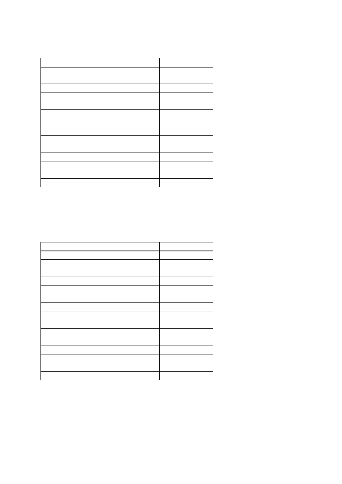
26.39 Multi22 (Compressor - Distortion - Chorus)
Parameter Number Parameter Name Value Notes
Parameter7[00] Cmp Depth 00 - 7F
Parameter7[01] CmpAttack 00 - 7F
Parameter7[02] Cmp Reles 00 - 7F
Parameter7[03] Cmp Level 00 - 7F
Parameter7[04] Dist Gain 00 - 7F
Parameter7[05] Dist Low 00 - 7F
Parameter7[06] Dist High 00 - 7F
Parameter7[07] DistLevel 00 - 7F
Parameter7[08] Cho Rate 00 - 7F
Parameter7[09] Cho Depth 00 - 7F
Parameter7[10] Chorus FB 00 - 7F Note1
Parameter7[11] ChoWetLvl 00 - 7F
Parameter7[12] Cho Polari 00 - 7F Note2
Parameter7[13] Dist Skip 00 - 7F Note3
Note 1: See “27.6 –64 - 0 +63 Setting Value Table”.
Note 2: See “27.2 –/+ Setting Value Table”.
Note 3: See “27.1 Off/On Setting Value Table”.
26.40 Multi23 (LFO Wah - Distortion - Chorus)
Parameter Number Parameter Name Value Notes
Parameter7[00] LWh Input 00 - 7F
Parameter7[01] LWh Reso 00 - 7F
Parameter7[02] LWhManual 00 - 7F
Parameter7[03] LWh Rate 00 - 7F
Parameter7[04] LWh Depth 00 - 7F
Parameter7[05] Dist Gain 00 - 7F
Parameter7[06] Dist Low 00 - 7F
Parameter7[07] Dist High 00 - 7F
Parameter7[08] DistLevel 00 -
Parameter7[09] Cho Rate 00 - 7F
Parameter7[10] Cho Depth 00 - 7F
Parameter7[11] Chorus FB 00 - 7F Note1
Parameter7[12] ChoWetLvl 00 - 7F
Parameter7[13] Cho Polari 00 - 7F Note2
Parameter7[14] Dist Skip 00 - 7F Note3
Note 1: See “27.6 –64 - 0 +63 Setting Value Table”.
Note 2: See “27.2 –/+ Setting Value Table”.
7F
Note 3: See “27.1 Off/On Setting Value Table”.
61

26.41 Multi24 (Auto Wah - Distortion - Chorus)
Parameter Number Parameter Name Value Notes
Parameter7[00] AWh Input 00 - 7F
Parameter7[01] AWh Reso 00 - 7F
Parameter7[02] AWhManual 00 - 7F
Parameter7[03] AWh Depth 00 - 7F Note1
Parameter7[04] Dist Gain 00 - 7F
Parameter7[05] Dist Low 00 - 7F
Parameter7[06] Dist High 00 - 7F
Parameter7[07] DistLevel 00 - 7F
Parameter7[08] Cho Rate 00 - 7F
Parameter7[09] Cho Depth 00 - 7F
Parameter7[10] Chorus FB 00 - 7F Note1
Parameter7[11] ChoWetLvl 00 - 7F
Parameter7[12] Cho Polari 00 - 7F Note2
Parameter7[13] Dist Skip 00 - 7F Note3
Note 1: See “27.6 –64 - 0 +63 Setting Value Table”.
Note 2: See “27.2 –/+ Setting Value Table”.
Note 3: See “27.1 Off/On Setting Value Table”.
26.42 Multi25 (Compressor - Distortion - Auto Pan)
Parameter Number Parameter Name Value Notes
Parameter7[00] Cmp Depth 00 - 7F
Parameter7[01] CmpAttack 00 - 7F
Parameter7[02] Cmp Reles 00 - 7F
Parameter7[03] Cmp Level 00 - 7F
Parameter7[04] Dist Gain 00 - 7F
Parameter7[05] Dist Low 00 - 7F
Parameter7[06] Dist High 00 - 7F
Parameter7[07] DistLevel 00 - 7F
Parameter7[08] APan Rate 00 - 7F
Parameter7[09] APanDepth 00 - 7F
Parameter7[10] Dist Skip 00
Parameter7[11] APan Skip 00 - 7F Note1
Note 1: See “27.1 Off/On Setting Value Table”.
- 7F Note1
62
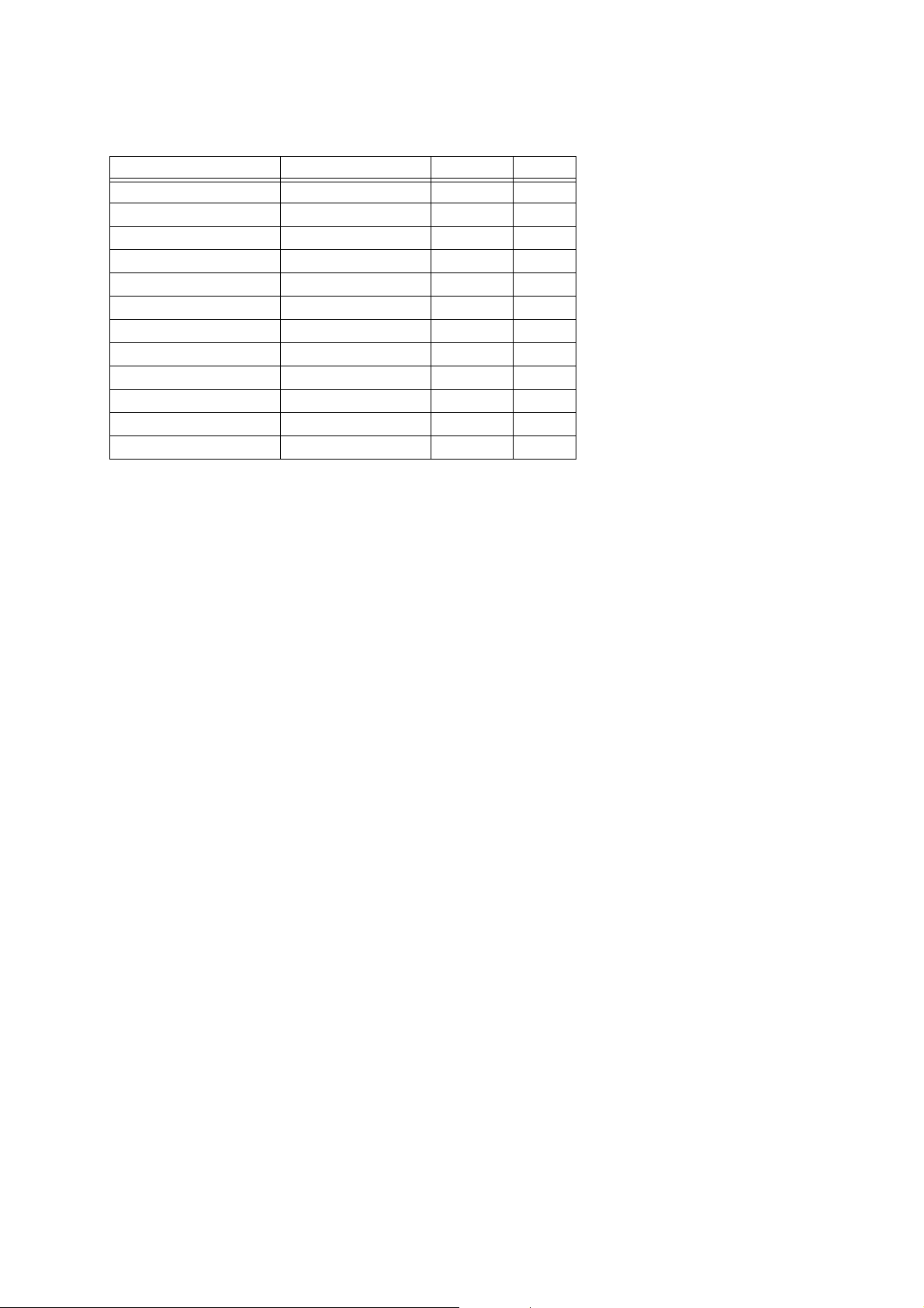
26.43 Multi26 (Compressor - Distortion - Tremolo)
Parameter Number Parameter Name Value Notes
Parameter7[00] Cmp Depth 00 - 7F
Parameter7[01] CmpAttack 00 - 7F
Parameter7[02] Cmp Reles 00 - 7F
Parameter7[03] Cmp Level 00 - 7F
Parameter7[04] Dist Gain 00 - 7F
Parameter7[05] Dist Low 00 - 7F
Parameter7[06] Dist High 00 - 7F
Parameter7[07] DistLevel 00 - 7F
Parameter7[08] Trem Rate 00 - 7F
Parameter7[09] TremDepth 00 - 7F
Parameter7[10] Dist Skip 00 - 7F Note1
Parameter7[11] Trem Skip 00 - 7F Note1
Note 1: See “27.1 Off/On Setting Value Table”.
63

Part VII
Setting Values and Send/
Receive Values
27 Setting Value Tables
27.1 Off/On Setting Value Table
Transmit Value Receive Value Parameter
00H 00H - 3FH Off
7FH 40H - 7FH On
27.2 –/+ Setting Value Table
Transmit Value Receive Value Parameter
00H 00H - 3FH -
7FH 40H - 7FH +
27.6 –64 - 0 - +63 Setting Value Table
Transmit/Receive Value Parameter
00H –64
01H –63
::
40H 0
::
7EH +62
7FH +63
27.7 –100 - 0 - +99 Setting Value Table
Transmit/Receive Value Parameter
(MSB-LSB)
00H - 00H –100
::
40H - 00H 0
::
7FH - 7FH +99
27.3 Slow/Fast Setting Value Table
Transmit Value Receive Value Parameter
00H 00H - 3FH Slow
7FH 40H - 7FH Fast
27.4 Rotate/Brake Setting Value Table
Transmit Value Receive Value Parameter
00H 00H - 3FH Rotate
7FH 40H - 7FH Brake
27.5 Routing Setting Value Table
Transmit Value Receive Value Parameter
00H 00H - 3FH Comp-Wah
7FH 40H - 7FH Wah-Comp
27.8 Pan Setting Value Table
Transmit/Receive Value Parameter
00H Left
::
40H Center
::
7FH Right
64

27.9 Reverb Type Setting Value Table
Transmit /
Receive Value
00H Room1 -
01H Room2 Room
02H Room3 -
03H Hall1 Large Hall
04H Hall2 Hall
05H Plate1 -
06H Delay -
07H Panning Delay -
08H Plate2 -
09H Plate3 -
0AH Large Room1 -
0BH Large Room2 -
0CH Stadium1 Stadium
0DH Stadium2 -
0EH Long Delay -
0FH Long Panning Delay -
Parameter Display
27.11 Equalizer Low Frequency Setting
Value Table
Parameter Value Frequency
00H 200Hz
01H 400Hz
02H 800Hz
27.12 Equalizer Mid Frequency Setting
Value Table
Parameter Value Frequency
00H 1.0KHz
01H 1.3KHz
02H 1.6KHz
03H 2.0KHz
04H 2.5KHz
05H 3.2KHz
06H 4.0KHz
07H 5.0KHz
27.10 Chorus Type Setting Value Table
Transmit /
Receive Value
00H Chorus1
01H Chorus2 -
02H Chorus3 Chorus
03H Chorus4 -
04H Feedback Chorus -
05H Flanger1 -
06H Short Delay -
07H Short Delay FB -
08H Soft Chorus -
09H Bright Chorus -
0AH Deep Chorus Deep Chorus
0BH Flanger2 Flanger
0CH Flanger3 -
0DH Flanger4 -
0EH
0FH
Parameter Display
LightChorus
Short Delay
Modulation
Short Delay
Modulation FB
-
-
27.13 Equalizer High Frequency Setting
Value Table
Parameter Value Frequency
00H 6.0KHz
01H 8.0KHz
02H 10.0KHz
65

27.14 Equalizer Gain Setting Value
Table
27.15 DSP Equalizer Gain Setting Value
Table
Parameter Value Gain
00H –12
01H –11
02H –10
03H –9
04H –8
05H –7
06H –6
07H –5
08H –4
09H –3
0AH –2
0BH –1
0CH 0
0DH +1
0EH +2
0FH +3
10H +4
11H +5
12H +6
13H +7
14H +8
15H +9
16H +10
17H +11
18H +12
Parameter Value Gain
34H –12
35H –11
36H –10
37H –9
38H –8
39H –7
3AH –6
3BH –5
3CH –4
3DH –3
3EH –2
3FH –1
40H 0
41H +1
42H +2
43H +3
44H +4
45H +5
46H +6
47H +7
48H +8
49H +9
4AH +10
4BH +11
4CH +12
Note:
The gain value does not exactly correspond to decibels (dB).
Note:
The gain value does not exactly correspond to decibels (dB).
66

Part VIII
MIDI Implementation
Notation
28 Value Notation
28.1 Hexadecimal Notation
MIDI implementation sometimes requires that data be
expressed in hexadecimal format. Hexadecimal values are
indicated by the letter “H” after the value. The hexadecimal
equivalents of decimal values 10 through 15 are expressed
as the letters A through F. The table below shows the
hexadecimal equivalents for decimal values 0 through 127,
which are often used in MIDI messages.
Decimal
Hexadecimal
0 00H 32 20H 64 40H 96 60H
1 01H 33 21H 65 41H 97 61H
2 02H 34 22H 66 42H 98 62H
3 03H 35 23H 67 43H 99 63H
4 04H 36 24H 68 44H 100 64H
5 05H 37 25H 69 45H 101 65H
6 06H 38 26H 70 46H 102 66H
7 07H 39 27H 71 47H 103 67H
8 08H 40 28H 72 48H 104 68H
9 09H 41 29H 73 49H 105 69H
10 0AH 42 2AH 74 4AH 106 6AH
11 0BH 43 2BH 75 4BH 107 6BH
12 0CH 44 2CH 76 4CH 108 6CH
13 0DH 45 2DH 77 4DH 109 6DH
14 0EH 46 2EH 78 4EH 110 6EH
15 0FH 47 2FH 79 4FH 111 6FH
16 10H 48 30H 80 50H 112 70H
17 11H 49 31H 81 51H 113 71H
18 12H 50 32H 82 52H 114 72H
19 13H 51 33H 83 53H 115 73H
20 14H 52 34H 84 54H 116 74H
21 15H 53 35H 85 55H 117 75H
22 16H 54 36H 86 56H 118 76H
23 17H 55 37H 87 57H 119 77H
24 18H 56 38H 88 58H 120 78H
25 19H 57 39H 89 59H 121 79H
26 1AH 58 3AH 90 5AH 122 7AH
27 1BH 59 3BH 91 5BH 123 7BH
28 1CH 60 3CH 92 5CH 124 7CH
29 1DH 61 3DH 93 5DH 125 7DH
30 1EH 62 3EH 94 5EH 126 7EH
31 1FH 63 3FH 95 5FH 127 7FH
Decimal
Hexadecimal
Decimal
Hexadecimal
Decimal
Hexadecimal
28.2 Binary Notation
When a MIDI implementation data value is expressed in
binary, the letter “B” (for “binary”) is affixed at the end of
the value. The table below shows the binary equivalents for
the decimal values 0 through 127, which are often used for
settings.
Decimal
125 7DH 01111101B
126 7EH 01111110B
127 7FH 01111111B
Hexadecimal
0 00H 00000000B
1 01H 00000001B
2 02H 00000010B
3 03H 00000011B
4 04H 00000100B
5 05H 00000101B
6 06H 00000110B
7 07H 00000111B
8 08H 00001000B
9 09H 00001001B
10 0AH 00001010B
11 0BH 00001011B
12 0CH 00001100B
13 0DH 00001101B
14 0EH 00001110B
15 0FH 00001111B
16 10H 00010000B
::
Binary
67

CASIO COMPUTER CO.,LTD.
MA1007-A
6-2, Hon-machi 1-chome
Shibuya-ku, Tokyo 151-8543, Japan
 Loading...