

Page 1
JD-6500(ZX-807AE)
INDEX
C-320(ZX-807BE)
JULY. 1995
(without price)
JD-6500
C-320
R
Page 2

CONTENTS
1. SPECIFICATIONS ......................................................................................................... 1
2. GENERAL GUIDE ......................................................................................................... 5
3. RESET OPERATIONS ................................................................................................ 10
4. ERROR MESSAGE ..................................................................................................... 11
5. BATTERY REPLACEMENT........................................................................................ 12
6. LSI PIN FUNCTION ..................................................................................................... 14
7. OPERATION CHECK .................................................................................................. 17
8. TO SAVE THE DATA TO OTHER UNIT ..................................................................... 19
9. TROUBLESHOOTING................................................................................................. 22
10. EXPLODED VIEW ....................................................................................................... 24
11. PARTS LIST ................................................................................................................ 25
12. SCHEMATIC DIAGRAM.............................................................................................. 27
Page 3

1. SPECIFICATIONS
Telephone Directory Mode
Storage and recall of telephone directory data (name, telephone number, address, etc.). Each item can contain
up to 380 characters with a Fun Face. Includes secret memory area and auto sort function.
Schedule Mode
Storage and recall of appointments for any date in the range of January 1901 through December 2099. Each
item can contain up to 372 characters with an icon. Includes secret memory area and auto sort function.
Calendar Mode
Full-month calendars in the range of January 1901 through December 2099. Includes highlighting of important
dates and holidays.
Data Memo Mode
Storage and recall of memos. Each item can contain up to 381 characters. Includes secret memory area and
auto sort function.
Timekeeping Mode
Average of accuracy ±3 seconds per day under normal temperatures: Home Time (year/month/date, AM/PM,
day of the week, city name, daylight saving/standard time): World Time: full automatic calendar: 12/24 hour
timekeeping format
Alarm Mode
Daily Alarm (20-second electronic buzzer): Schedule Alarm (20-second electronic buzzer): Hourly Time Signal
(beeps every hour on the hour)
Conversion Mode
Six built-in conversion pairs (4-character unit name + 10 digit rate; user-definable)
Pet Mode
Magic Beam Mode
Data communications using infrared light (messages up to 28 characters and Telephone Directory data)
Calculator Mode
10-digit arithmetic calculations; constant calculations; memory calculations; 20-digit approximations; percentage calculations; square roots; sign changes; function command signs
Other functions
Contrast adjustment
— 1 —
Page 4

General
Display: Liquid crystal display
Memory Capacity: 4,096 bytes
Power Supply: Main batteries – Two AAA-size batteries (LR03 (AM-4) or R03 (UM-4))
Back-up battery – One lithium battery (CR2032)
Power Consumption: 0.2W
Battery Life*: Main batteries –
LR03 (AM-4)
•approximately 380 hours continuous operation
•approximately 1.5 years (1 hour use per day)
R03 (UM-4)
•approximately 300 hours continuous operation
•approximately 1year (1 hour use per day)
Back-up battery – approximately 2 years after the low main battery warning
appears on the display (approximately 5 years if main batteries are replaced immediately whenever battery warning
appears)
*The batteries that have been installed in this unit when user purchased it had been
used in the factory test, so it will be impossible to fully satisfy this specifications
when these batteries are used.
Auto Power Off: Approximately 6 minutes after last key operation
Ambient Temperature
Range: 0°C ~ 40°C (32°F ~ 104°F)
Dimensions: Open: 13.5 (H) × 145 (W) × 180 (D) mm
Closed: 15.75 (H) × 145 (W) × 96.5 (D) mm
1
(
/2" (H) × 5 3/4" (W) × 7 1/8" (D))
5
(
/8" (H) × 5 3/4 " (W) × 3 3/4" (D))
Weight: 142.2 g (5 oz) including batteries
— 2 —
Page 5
Current consumption
Check point TYP [µA] Max [µA]
OFF CP1 - CP3 — 28
ON (Menu) CP1 - CP3 190 300
ON (Buzzer) CP1 - CP3 — 5000
ON (Infrared) CP1 - CP3 — 75000
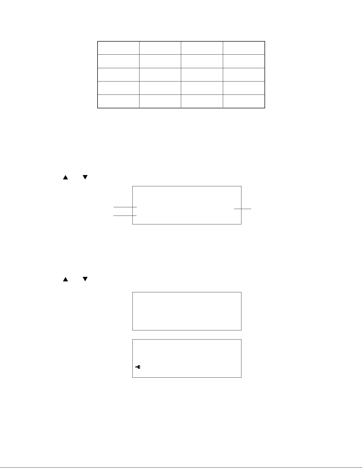
Memory Capacity Screen
Use the following procedures to check the status of the memory. One procedure displays the amount of
memory used and how much memory is remaining. The other shows you how many data items you have stored
in each mode.
To display the memory capacity:
1. While the main menu is displayed, or any time you are in the Telephone Directory, Schedule, Data Memo,
or Calendar mode, press FUNCTION.
2. Use and to select "Memory Capacity" and then press EXE.
Memory Capac i ty
Remaining memory
(Unit: bytes)
Memory used
(Unit: bytes)
F ree 3929
Used 167
Memory used
4 %
• The memory values shown above are the total for both the Open Memory Area and the Secret Memory
Area.
• Press AC/ON to clear the memory capacity screen.
To display the number of items in each mode:
1. While the main menu is displayed, press FUNCTION.
2. Use and to select "Number of items" and then press EXE.
Open Memory Area
T elephone : 15
Schedule : 3
Data Memo : 7
Secret Memory Area
T elephone : 3
Schedule : 2
Data Memo : 11
• If you perform the above procedure while in the Open Memory Area, the number of items stored in the Open
Memory Area only are displayed. To see the number of items in the Secret Memory Area, you must perform
the above operation while accessing the Secret Memory Area.
How memory capacity is calculated
There is no limit on the amount of memory you can use in each mode, but the total amount of data that can
be stored is 4,096 bytes. The following shows how many bytes the data in each mode takes up. One character
(each newline operation counts as a character also) takes up one byte.
— 3 —
Page 6
Mode Bytes per Data Item
Telephone Directory (name) + (telephone number) + (address. etc.) + 15
Schedule (description) + 12
Calendar 6 bytes per calendar that contains highlighted dates
Data Memo (memo name) + (memo contents) + 3
Examples:
Telephone Directory data only
When all items use 10 characters for the name, 12 characters for the phone number, and 16 characters
of the address, you can store approximately 70 items.
Schedule data only
When all items use 20 characters, you can store approximately 120 items.
Data Memo data only
When all items use 10 characters for the memo name and 10 characters for the memo content, you can
store approximately 170 items.
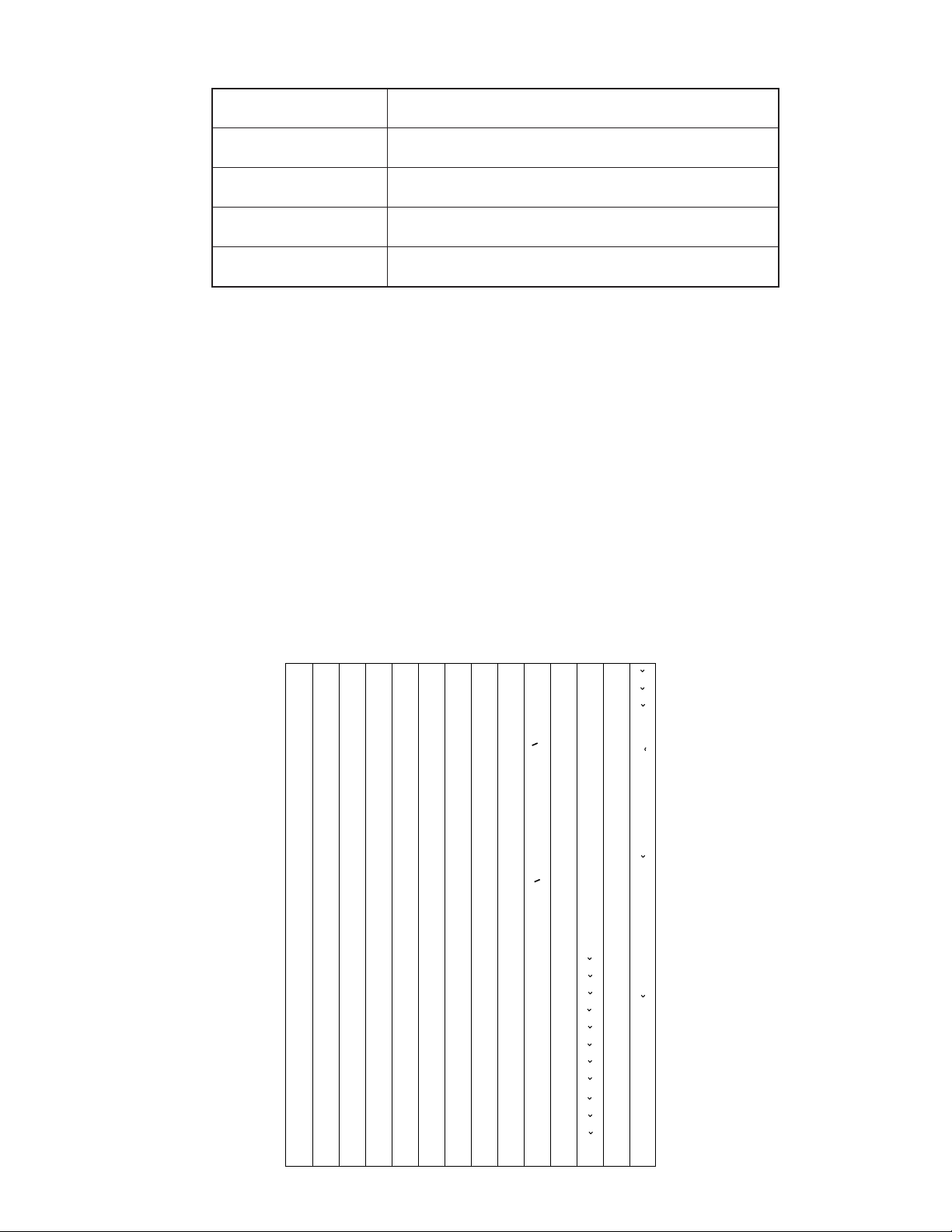
Sort Sequence
The following table shows the sequence used for sorting data in the Telephone Directory and the Data Memo
Mode.
1
2
3
4
5
6
7
8
9
10
11
12
13
14
15
16
17
18
19
20
21
22
23
24
25
26
27
28
29
§
→
←
÷
×
Space
!
”
#
$
%
&
’
(
)
∗
+
,
–
•
/
0
1
2
3
4
5
6
7
30
31
32
33
34
35
36
37
38
39
40
41
42
43
44
45
46
47
48
49
50
51
52
53
54
55
56
57
58
@
G
H
K
M
N
O
P
Q
R
S
U
Ì
117
t
88
V
59
8
Ò
118
u
89
W
60
9
Ù
119
v
90
X
61
:
Ç
120
w
91
Y
62
;
L
121
x
92
Z
63
<
y
93
„
64
>
z
94
¥
65
?
“
66
¡
67
A
¿
68
B
a
69
C
b
70
D
c
71
E
d
72
F
e
73
f
74
g
75
I
h
76
J
i
77
j
78
L
k
79
l
80
m
81
n
82
o
83
p
84
q
85
r
86
T
s
87
95
96
97
98
99
100
101
102
103
104
105
106
107
108
109
110
111
112
113
114
115
116
<
<
£
>
>
~
Á
É
Í
Ó
Ú
Ã
Õ
Ñ
á
é
í
ó
ú
ã
õ
ñ
À
È
122
123
124
125
126
127
128
129
130
131
132
133
134
135
136
137
138
139
140
141
142
143
144
145
Ä
Ë
Ö
Ü
Æ
Œ
O
æ
œ
.
Z
à
è
ì
ò
ù
ç
l
.
z
Ï
"
ä
ë
ï
ö
ü
146
147
148
149
150
151
152
153
154
155
156
157
158
159
160
161
162
163
164
165
166
167
168
169
170
171
172
173
174
"
o
Â
Ê
Î
Ô
Û
Å
.
U
"
U
â
ê
î
ô
û
å
.
u
"
u
A
E
C
D
N
R
S
T
a
e
c
d'
175
176
177
178
179
180
181
182
183
184
185
186
187
188
189
190
191
192
193
194
195
196
197
n
r
s
t'
A
E
`
´
C
´
N
´
S
´
Y
´
Z
Z
a
`
e
`
c
´
n
´
s
´
y
´
z
´
z
Ø
ø
ß
— 4 —
Page 7
2. GENERAL GUIDE
Very important stuff! Here's where we tell you how not to lose important data stored in memory. Also, be
sure to perform the all-reset operation before using the unit for the first time. The all-reset operation is
described on section 4.
Please be sure you understand the following before using the unit.
Make back-up copies of important data!
The electronic memory in the unit store and recall information quickly and easily. But that information is
retained only as long as power is supplied by the batteries. Should the batteries go dead, or should you
remove both batteries at the same time, data stored in memory can be lost entirely. Data can also be
corrupted or lost due to a strong electrostatic charge, strong impact, or extremes in temperature and
humidity. All of this means that you should always keep written back-up copies of important data.
General Precautions
Warning!
• Never expose the unit or batteries to direct heat or flame.
• Avoid use or storage in very low temperatures. This may cause display response to slow down or fail
entirely. Very low temperatures can also shorten battery life.
• Avoid use or storage in very high temperatures. Even prolonged exposure to direct sunlight can damage
the unit. Leaving it on the dashboard of a closed car, or on a heater, is even worse.
• Avoid using or storing the unit where there is high humidity or a lot of dust. Never allow liquids to come
into contact with the unit.
• Avoid dropping the unit or otherwise subjecting it to strong impact.
• Never bend or twist the unit. Carrying it in your back pocket, for instance, can subject the unit to abnormal
bending and twisting.
• Never try to take the unit apart.
• Do not press the unit's keys with a pen, pencil, or other sharp object.
• To clean the unit, wipe it with a soft cloth. When necessary, you may wipe the exterior with a soft cloth
that has been dipped in a weak solution of a mild, neutral detergent and water.
• Never use strong liquid cleaners such as lacquer thinner or benzine to clean the unit.
• In no event will CASIO or its suppliers be liable to you or any other person for any damages, including
any incidental or consequential expenses, lost profits, lost savings, or any other damages arising out
of the use of this product.
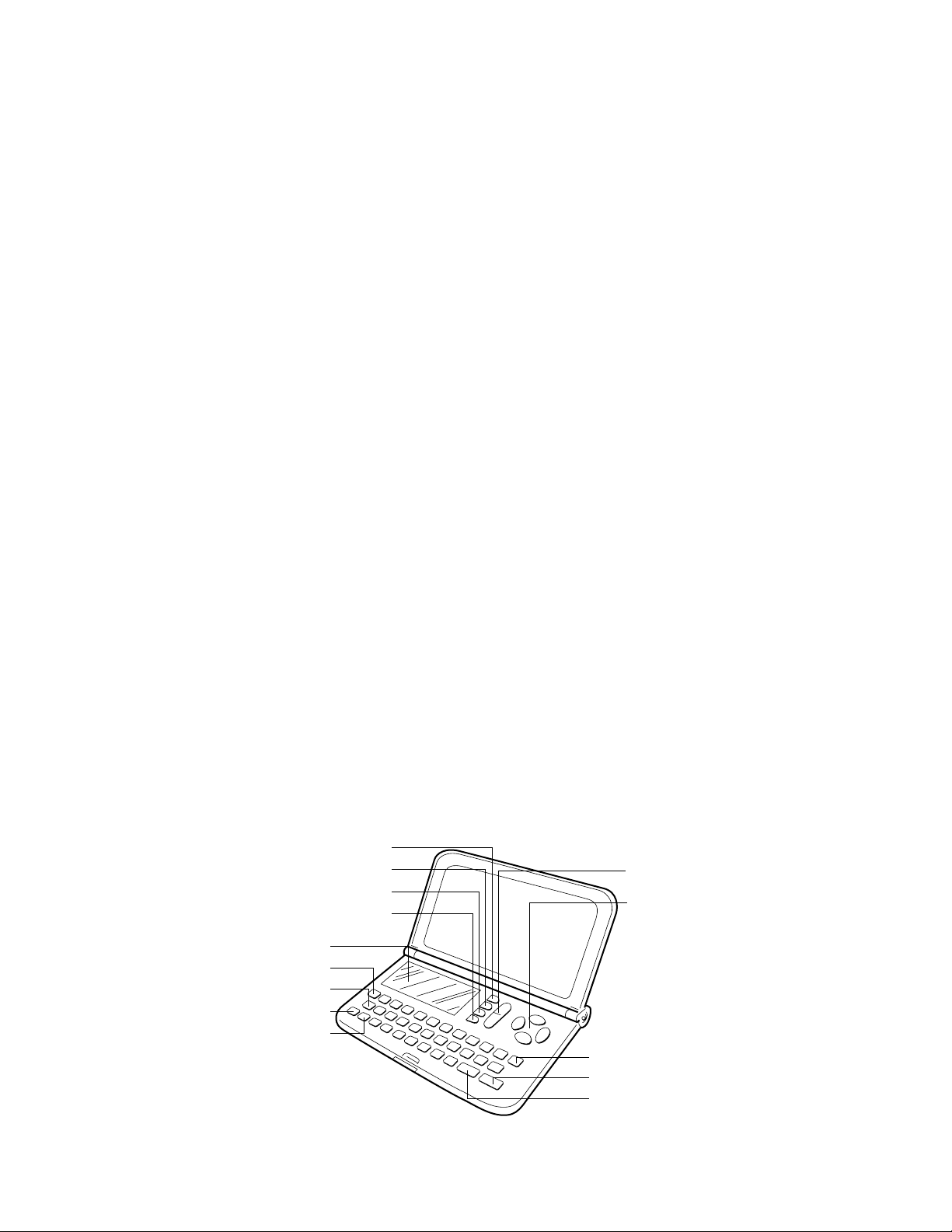
MENU Key
Pet Mode Key
Timekeeping Mode Key*
FUNCTION Key
Display
CODE Key
Clear Key
AC/ON Key
SHIFT Key
SERCH Key
Cursor Keys
OFF Key
EXE Key
SPACE/Return Key
* In this manual, all references to the HOME TIME/WORLD TIME key are indicated by TIME.
— 5 —
Page 8
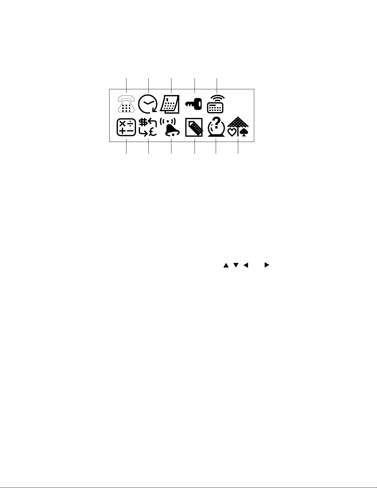
Displaying the Main Menu
The main menu appears on the display when you switch the power on. Whenever you are viewing any other
screen, you can always press MENU to return to the main menu.
Main Menu
Menu Icons
1 Telephone Directory Mode 6 Calculator Mode
2 Schedule Mode 7 Conversion Mode
3 Calendar Mode 8 Alarm Mode
4 Secret Memory Area 9 Data Memo Mode
5 Magic Beam Mode 0 Fortune Telling Mode
12345
67890A
A Match Maker Mode
Entering Modes
To Enter a Mode:
1. Display the main menu.
2. The icon of the current mode is highlighted on the display . Use , , , and to select another menu
icon.
3. When you have highlighted the mode you wish to select, press EXE.
To enter the Timekeeping Mode, press TIME key. To enter the Pet Mode, press PET. You can not select these
modes from the main menu.
— 6 —
Page 9

Using the FUNCTION Key
To view the function menu, press FUNCTION.
To select a function:
1. Use or to highlight the function you want to choose.
2. Press EXE.
If another function menu appears repeat steps 1 and 2.
To backstep to a previous display, press FUNCTION.
To exit the function menu, press AC/ON.
Setting the System Language
The unit can produce display messages in any one of ten language: English, Spanish, Italian, German, French,
Danish, Swedish, Dutch, Finnish, and Portuguese.
To set the system to another language:
1. Display the main menu.
2. Press FUNCTION, then use or to highlight "Language." Press EXE.
3. Use or to highlight the language you want. Press EXE.
Also note the word "Language" is displayed in each language.
To Adjust the Display Contrast
1. Display the main menu.
2. To darken the figures on the display, press . To make them lighter, press .
To Switch the Key Input Tone On or Off
1. Display the main menu.
2. Use , , , and to highlight . Press EXE.
3. Press FUNCTION. Then use to highlight "Sound," Press EXE.
4. Use to highlight "Key Tone." Use and to switch the key tone on and off. Press EXE.
Auto Power Off Function
This function automatically switches off the power if you do not touch any of the unit's keys for about six minutes.
To restore power, press AC/ON.
If you do not touch any keys for six minutes while entering or editing data, setting the current time, or setting
an alarm time, power cuts off without storing the data.
If you have set an alarm to go off, and the unit has been shut down by auto power off, the alarm will sound
anyway at its appropriate time.
— 7 —
Page 10

Features and Functions
Telephone Directory Mode
Use this to keep names, phone numbers, and addresses. You can also include fun faces of the
people whose names and addresses you keep.
Schedule Mode
Stores the date, time, and type of each appointment. You can select icons to indicate each
appointment at a glance.
Calendar Mode
Displays the calendar for any month from January, 1901 to December, 2099. You can specify
holidays for highlighting.
Data Memo Mode
Stores notes and special thoughts. Diary entry consists of a memo name and the memo's contents.
Secret Memory Area
Stores your private thoughts you wish to keep confidential. No one can gain access to the Secret
Memory Area without knowing your password.
Timekeeping Mode
Home Time displays the current time where you are. World Time shows the time in any of 29 zones
around the globe. You can use 24-hour or 12-hour format, and can even specify daylight savings
time.
Alarm Mode
Lets you set alarms to the minute, for alarms to go off every hour, or for a single time each day. You
can also set the Schedule Alarm and control the key input tone.
Conversion Mode
Helps you compare US dollar values against six foreign currencies (monies), or with combinations
of currency units.
Calculator Mode
A 10-digit calculator performs most common numerical operations including percents, square roots
and memory.
Fortune Telling Mode
Once you have entered your birthday, you can check your fortune today, or for any day. Have fun
telling your friend's fortune too.
Match Maker Mode
Tells you whether or not you are compatible with that special someone.
Pet Mode
You can play with cute little puppy that romps on the display.
— 8 —
Page 11

Magic Beam Mode
Makes it possible to communicate with another unit using infrared light, without direct communication.
Effective range
Approximately 8 meters
(8.7 yards)
20°
About the "Check time!" Display
When the message, "Check time!" appears on the display, press any key to display the current time. Make sure
the unit has the correct time before performing any other operation. If the setting is not correct, use the
procedure for "Setting the Date and Time" in the Operation Manual to change it.
— 9 —
Page 12

3. RESET OPERATIONS
RESET button
RESET
Two kinds of reset operations can be performed:
•
All-reset operation
•
Secret-reset operation
Important!
• Do not use a very sharp pencil to press the RESET button. Doing so can damage the unit.
• Be sure to perform the all-reset operation before you use the unit for the first time.
• After check to make sure that the main batteries and back-up battery are correctly installed, perform the
RESET operation.
To Perform All-Reset:
1. Switch the power off.
2. Remove the screw that holds the small battery compartment cover in place, then remove the small
battery compartment cover.
3. Press the RESET button on the back of the unit
with a thin, pointed object.
4. Press to select "Reset," then press EXE.
5. Press to select "Yes, " then press EXE.
6. The main menu will appear and all data will be
deleted.
7. Replace the battery compartment cover and
the screw that secures it in place.
If you want to cancel the reset operation
immediately after you have pressed the RESET
button, select "Exit," then press EXE.
To Perform Secret Reset:
• Perform the steps described under "To Perform All-reset" above, but select "Del Secret Data" in place
of "Reset" in step 4.
deletes all data in memory.
deletes only your password and the data in the Secret Memory Area.
Following are the initial settings produced by the all-reset operation:
Home Time Zone: London (LON)
Home Time Setting: 12:00 AM, January 1, 1990
World Time: New York (NYC)
12/24-Hour Clock: 12-Hour Clock
Alarm: OFF
Alarm Time: 12:00 AM
Hourly Time Signal: OFF
Key Input Tone: ON
Date Format: Month/Day/Year
Language: English
When the Unit Does Not Work Correctly...
If the unit is jolted by a strong electrostatic charge or by severe impact, it may not work properly. In such
a case, first check to make sure that the main batteries and back-up battery are correctly installed, and then
perform the following operation:
1. Remove the screw that holds the small battery compartment cover in place and remove the small battery
compartment cover.
2. Press the RESET button with a thin, pointed object.
3. Look for the message, "Exit," to be highlighted on the display.
4. Press EXE. Now the message, "Check time!" should be on the display.
— 10 —
Page 13

4. ERROR MESSAGE
Message
Memory Full!
No Record!
Not Found!
Password
Mismatch!
Main Battery
Getting Weak!
Replace it!
Communication
Error
Meaning
Not enough room to store the data
you are trying to save.
You tried to perform a search
operation while there is no data
stored in memory.
There is no data that matches your
search specification.
The password you input to access
the Secret Memory Area does not
match the one that is registered.
The main batteries are weak.
• Error during data communications
using Magic Beam.
• Magic Beam data communications
interrupted.
Action
Press AC/ON and then delete
data you no longer need from
memory.
Input data before attempting
search operations.
Press or to recall your
search data. You can then edit
the previous data or input new
data.
Input the password correctly.
Replace the batteries in
accordance with the
instructions of this manual.
Correct problem and try again.
— 11 —
Page 14

5. BATTERY REPLACEMENT
Low Battery Warning
The message, "Main Battery Getting Weak! Replace it!" appears whenever battery power drops below a
certain level. Replace the main battery immediately after this message appears.
Whenever the low battery warning message appears, the OFF key will be the only function that works. If you
don't turn the unit off yourself, power will switch off automatically about 30 seconds after the low battery warning
appears.
Replacing Batteries
• Main Batteries
Two AAA size batteries (LR03 (AM-4) or R03 (UM-4)) are used for the main power supply. The unit will not
operate at all if main batteries are not installed.
• Back-up Battery
One CR2032 lithium battery supplies power to the memory and protects its contents.
Memory contents are lost when both the main batteries and the back-up battery are removed. Be sure always
to leave one of the batteries or back-up battery in place to protect memory contents. If, however, you remove
the main battery for any time, memory retention will depend entirely on the condition of the back-up battery.
Over a long period of time with just the back-up battery in place, memory contents are likely to be damaged.
If memory seems corrupted, clear it using the RESET procedure described on section 4.
Important!
Incorrect use of batteries can cause them to burst or leak, possibly damaging the interior of the unit. Note the
following precautions:
• Be sure that the positive (+) and negative (–) poles of the batteries are facing in the proper direction.
• Never leave dead batteries in the battery compartment.
• Remove the batteries if you expect not to be using the unit for a long period of time.
• To avoid damage to the unit from leaky batteries, replace the main batteries at least every two years, and
the back-up battery every five years. Batteries should be replaced no matter how much you use the unit
during that time.
• Never mix batteries of different types.
Warning!
• Never try to recharge the batteries supplied with the unit.
• Do not expose batteries to direct heat, short-circuit them, or try to take them apart.
• Keep batteries out of the reach of small children. If swallowed, consult a physician immediately.
— 12 —
Page 15

To replace the main batteries
1. Switch power off.
2. Loosen the screw of the large battery compartment cover on the back of the unit, and slide the battery
compartment cover in the direction noted by the arrow. (Figure 1)
3. Remove the old batteries.
4. Making sure that the positive (+) and negative (-) ends of the batteries are facing correctly, load two new
batteries into the compartment. (Figure 2)
• Be sure to replace both old batteries with two new ones.
5. Insert the tabs on the bottom of the battery compartment cover into the slots of the battery compartment
and carefully close the cover. Secure the cover in place with the screw. (Figure 3)
Figure 1 Figure 2 Figure 3
To replace the back-up battery
1. Switch power off.
2. Loosen the screw of the small battery compartment cover on the back of the unit, and remove the back-
up battery compartment cover. (Figure 4)
3. Remove the old battery.
4. Wipe off a new battery with a soft cloth.Then, load it into the compartment making sure that positive (+) side
is facing up (so you can see it.) (Figure 5)
5. Insert the tabs on the bottom of the battery compartment cover into the slots of the battery compartment
and carefully close the cover. Secure the cover in place with the screw. (Figure 6)
Figure 4 Figure 5 Figure 6
— 13 —
Page 16

6. LSI PIN FUNCTION
1. CPU (HC3000-08-F1)
Pin No. Signal In/Out Function
1 VREG3 Out Power supply for RAM / 3(V)
2 DUMMY – Not used
3 ~ 5 KO10 ~ 12 Out Not used
6 ~ 14 KO1 ~ 9 Out Key scan signal
15 KI8 In Not used
16 ~ 22 KI1 ~ 7 In Key input signal
23 , 25 TRANS, DUMMY – Not used
24 BUFON Out Power supply control for ROM
26 IT2 In Interrupt signal input
27 IT0 In Reception data input
28 AO17 Out Not used
29 ~ 45 AO0 ~ 16 Out Address bus
46 OEB0 Out Output enable signal for RAM and ROM
47 WEB0 Out Write enable signal for RAM
48 ~ 52 – Not used
53 CS7B0 Out Chip enable signal for RAM
54 CS6B0 Out Chip enable signal for ROM
55, 56 Out Not used
57 ~ 64 IO0 ~ 7 In/Out Data bus
65, 66 – Not used
67 OPT6 Out Turn on signal for Photo Sensor
68, 72 OPT1, 5 Out Turn on signal for LED (Infrared)
69 ~ 73 – Not used
74 PORT7 – Interrupt port
— 14 —
Page 17

Pin No. Signal In/Out Function
75 ~ 77 PORT4 ~ 6 In/Out For data communication
78, 79 PORT2, 3 – Interrupt port
80 PORT1 In Communication data through Photo Sensor
81, 82 – Not used
83, 84 PI, PO In/Out Main clock terminal (3.45 MG)
85 DUMMY – Not used
86, 87 XI, XO In/Out Clock terminal (DT-26S)
88 DUMMY – Not used
89 ~ 184 S1 ~ 96 Out Segment signal for display
185 ~ 216 C1 ~ 32 Out Common signal for display
217 VSSR In GND / 0[V]
218 ~ 222 V0 ~ 4 Out The voltage for LCD drive
OFF : 0[V]
ON; V0 : 3.6 (Min) ~ 5.8 (Max) [V]
V1 : 2.9 (Min) ~ 4.6 (Max) [V]
V2 : 2.1 (Min) ~ 3.5 (Max) [V]
V3 : 1.4 (Min) ~ 2.4 (Max) [V]
V4 : 0.7 (Min) ~ 1.2 (Max) [V]
223, 224 VSS In GND / 0[V]
225 DUMMY – Not used
226 VCC In Power supply / 3[V]
227 VREG2 Out 2 [V]
228, 229 TS1, 2 – Test for manufacturer
230, 231 BZ1, 2 Out Buzzer terminal
232 SW1 In 2.6[V]
While pushing the reset button: 0[V]
233, 234 VD1, 2 – VD1: 4.7[V] VD2: 1.6[V]
235, 236 VD3, 4 – VD3: 4.7[V] VD4: 1.6[V]
— 15 —
Page 18

Pin No. Signal In/Out Function
237 VDB In Low battery detection
4.4[V] < VDB < 5.2[V] ⇒ Low battery message
238, 239 VREG1, 4 – VREG1: 2.6 [V]
VREG4: 5.0 [V]
240 ~ 243 VT1 ~ 4 – VT1 : 1.0[V] VT2 : 2.9[V]
VT3 : 2.0[V] VT4 : 3.9[V]
244 VLCD Out 5.9 [V]
2. RAM (LC3564QM-85)
Pin No. Signal In/Out Function
1 NC – No connect
2 ~ 10 A0 ~ 7, 12 In Address bus
11 ~ 13 I/O 0 ~ 2 In/Out Data bus
14 GND In GND / 0[V]
15 ~ 19 I/O 3 ~ 7 In/Out Data bus
20 CE In Chip enable signal
21 A10 In Address bus
22 OE In Output enable signal
23 ~ 25 A8, 9, 11 In Address bus
26 CE2 In Chip enable signal
27 WE In Write enable signal
28 VCC In Power supply / 3[V]
— 16 —
Page 19

7. OPERATION CHECK
CAUTION : If customer's data are stored in the unit, all data will be corrupted by this operation.
STEP OPERATION DISPLAY NOTE
MENU
1
2
3
4
5
6
Then short in the checkpad
about two seconds.
EXE
2
1
EXE
EXE
Caution!
This is TEST
To Escape
Press AC KEY
1. Service Trans
2. TEST
AC. Esc
1. RAM, ROM 2. DISP
3. KEY 4. TRANS
5. RESET 6. FCC
7. OPT AC. Esc
8K RAM OK!
ROM OK!
1. RAM, ROM 2. DISP
3. KEY 4. TRANS
5. RESET 6. FCC
7. OPT
The checkpad is located
right side of the back-up
battery switch as shown
in figure on the next page.
RAM check
ROM check
7
8
9
10
11
2
EXE
EXE
EXE
EXE
All dots display
No display
Checker display
Reverse checker display
Frame display
DISPLAY check
Do
Do
Do
Do
— 17 —
Page 20

STEP OPERATION DISPLAY NOTE
12
13
14
15
16
17
EXE
3
MENU TIME FUNC
. . . . . .
M
SPACE
7
Press 3 then locate your
hand in front of Magic Beam
ports 5 to 10 cm away.
Same display as in step6.
MENU
TIME, FUNC, · · · SPACE/
Same display as in step 6.
1. TRAN
2. RCV (MASTER)
3. PET
PET OK!
Key check
Push the key sequentially
appeared on the display.
Check the key sound.
18
19
EXE
5
RESET
Same display as in step 6.
RESET!
Button battery
After a half second, the
menu will appear.
Checkpad
— 18 —
Page 21

8. TO SAVE THE DATA TO OTHER UNIT
UNIT 2
DTC 114YK
MA704
MA704
51K 1K
DP1
CP50
CP51
CP52
GND
Tx
Rx
UNIT 1
3 pins cable
It is commonly necessary to save all data stored in the customer's unit before repairing it.
For this purpose, you can transfer the data of the JD-6500 or C-320 unit to another unit using the
following procedure.
(1)To reset the receiving unit
Please reset the unit used to receive the data from the customer's unit according to the method
mentioned in section 3.
(2)To connect transmission unit with receiving unit
Please remove the covers of battery compartments from both the transmission unit and the
receiving unit, and connect one with another as shown in the figures below:
Button battery
DP1
CP50
RESET
Checkpad
CP52
CP51
DP1
CP50
DTC114YK
GND
Tx
CP51
51K
1K
CP52
MA704
MA704
Rx
— 19 —
Page 22

(3)To do data transfer
Please switch both units on, and make them enter the MENU1 mode. Thus you may start to
transfer all data of customer’s unit to the receiving unit following the procedure shown below.
AC
SLAVE UNIT
MENU 1 MENU 1
TEST
Caution!
This is TEST
To Escape
Press AC KEY
EXE
1. Service Trans
2. TEST
AC. Esc
1
Service Trans
1. TRANS 2. RCV
AC. ESC
Over 2 seconds
MASTER UNIT
TEST
Over 2 seconds
Caution!
This is TEST
To Escape
Press AC KEY
EXE
1. Service Trans
2. TEST
AC. Esc
1
Service Trans
1. TRANS 2. RCV
AC. ESC
AC
2
1
Receive OK!
Receiving
failed
To Stop
Now Sending!
Press AC KEY
To Stop
Receiving succeeded
Press AC KEY
Sending succeeded
MENU 1
MENU 1
Rcv Error ! Send Error !
Note: The TEST means the short-circuit operation as shown in figure on the next page:
Sending
failed
— 20 —
Page 23

Shortcircuit the two shorting pads with
a shorting pin for over 2 seconds.
Shorting pin
Shorting pads
Main battery
— 21 —
Page 24

9. TROUBLESHOOTING
1. Intermittent display
START
Is the Heat seal defective ?
Is the battery contact weak ?
Are there short circuit around the pins
of the LSI (HC3000-08-F1) ?
Is the soldering weak ?
Replace the Z807-1 PCB ass'y.
2. Erratic display
Is the Heat seal defective ?
Is the LCD defective ?
Are the voltage V0 ~ V4 OK ?
Are there short circuit around
the pins of the RAM and ROM ?
Replace the Z807-1 PCB ass'y.
Y
N
N
N
N
START
N
N
Y
Are there short circuit around the pins of the
LSI (HC3000-06-F1) or between the pins of
the crystal oscillator (·2) ?
N
N
Y
Y
Y
Y
Y
N
Y
Replace
Clean and adjust pressure of contact
Resolder
Resolder
Replace
Replace
Check or replace the chip
capacitors C4 ~ C8
Y
Resolder
Resolder
— 22 —
Page 25

3. No display
START
Is the battery contact weak?
Y
N
Is the battery switch contact weak?
N
Is the AC key contact weak?
Y
N
Are there short circuit around
Y
the pins of the LSI?
N
Is the voltage VCC 3[V] ?
N
Y
Does the ceramic oscillator oscillate ?
Y
Are the voltage V0 ~ V4 OK ?
Are the chip capacitors C22, C23 defective ?
Y
N
Is the heat seal defective ?
Is the LCD defective ?
Clean and adjust pressure of contact
Y
Clean and adjust pressure of contact
Clean or replace the rubber key
Resolder
Check or replace the electrolytic
capacitor C1
N
N
Replace the ceramic oscillator
Y
Replace
N
Y
Replace
N
Y
Replace
Are the voltage VD1 ~ VD4 OK ?
Y
Are the voltage VT1 ~ VT4 OK ?
Y
Are the voltage VREG 2 and
VREG 4 OK ?
Y
Is the voltage VREG 3 OK ?
N
Y
Is the voltage SW OK ?
N
Y
Replace the Z807-1 PCB ass'y.
N
Check or replace the chip
capacitor C11, C12
N
Check or replace the chip
capacitor C13, C14
N
Check or replace the chip
capacitor C9 or C16
Check or replace the chip
capacitor C18 or C25
Check or replace the chip
capacitor C10
— 23 —
Page 26

10. EXPLODED VIEW
18
11
14
9
2
1
13
DISASSEMBLY
1. Remove 2 screws
battery cover
P, then remove
E and F.
2. Remove 2 AAA-size batteries and 1
4
44
5
12
3
LED1
43
LSI
29
34
35
32
21
19
6
29
23
31
24
7
29
28
27
37
lithium battery.
3. Remove 3 screws
the Lower case
4. Remove 3 screws
the Z807-1 ass'y
8
IC6
IC6 (1PIN)
46
22
17
\, then remove
0.
S, then remove
8.
PCB - Z807 - 2
2
GND
3
Q4Q5
± 2
3
45
5
IC9 (5PIN)
IC9 (4PIN)
4
0
+ 1
0
30
33
10
Battery
— 24 —
26
38
16
25
20
21
39
36
15
26
Page 27

11. PARTS LIST
FOB Japan
N Item Code No. Parts Name Specification Q M N.R.Yen R
Unit Price
Z807-1 PCB ASS'Y
LSI 6411 1872 COF3000F1 SUB ASS'Y A312545B*8
IC1 2011 4088 LSI(RAM) LC3564QM-85
N IC2 2012 1176 LSI(ROM) uPD23C1001EAGW-N09
IC4 2105 2471 CMOS IC RH5RC502A-T1
IC6 3122 2576 Remote control receiver SBX8025-H
IC7 2105 0686 L-MOS TC4S69F-TE85R
IC8 2105 2898 L-MOS TC7W04F-TE12L
Q1 2250 0700 Chip transistor 2SA1753-ES5,ES6-TB
Q4 2221 0378 Chip transistor 2SC2812-L5,L6-TB
Q5,6,7 2252 0945 Transistor 2SC4577-UT5,UT6-TB
X1 7110 0642 Crystal oscillator DT-26S
X2 2590 1498 Ceramic oscillator CSA3.45MG
D1,3 2390 0364 Schottky diode MA713-TX
D2 2390 0959 Chip diode MA721-TX
LED1 2370 0945 LED SIR-563SB3F-P,Q
R11 2796 1505 Chip resistor RC210B51K-J-T
R23,31 2792 0470 Chip resistor MCR10EZHJ102
R4 2796 0476 Chip resistor RC210B47K-J-T
R7~10, 2796 1519 Chip resistor RC210B82K-J-T
13,16,17
R12 2796 0315 Chip resistor RC210B33K-J-T
R19,28 2795 2898 Chip resistor MCR10EZHJ106
R20 2796 1239 Chip resistor RC210B2.7K-J-T
R21,27 2796 1246 Chip resistor RC210B240K-J-T
R22,30 2792 0217 Chip resistor MCR10EZHJ101
R24 2795 4179 Chip resistor MCR18EZHJ2R2
R25 2792 0807 Chip resistor MCR10EZHJ470
R26 2792 0831 Chip resistor MCR10EZHJ103
N R32 2795 2233 Chip resistor MCR10EZHJ621
C1 2803 7688 Electrolytic capacitor RC3-6V220M-T10
C3,9,13, 2845 1925 Chip capacitor MCH312F105ZP
14,16,17
C4~8, 2845 1540 Chip capacitor MCH212F104ZK
10,19,25
C11,12 2845 3486 Chip capacitor MCH312F474ZP
N C15 2803 8052 Electrolytic capacitor RC3-T106V100M-T10
C18,26,27 2803 7597 Electrolytic capacitor (v) RC2-16V470M-T10
C20 2845 1652 Chip capacitor MCH215A180JK
C21 2845 1659 Chip capacitor MCH215A150JK
C22,23 2845 2499 Chip capacitor MCH215A300JK
C24 2845 2030 Chip capacitor MCH215C102KK
N C30 2896 1925 Chip capacitor MCH215C391KK
N C32 2803 8059 Electrolytic capacitor RC3-10V330M-T10
N L1 3841 1610 Coil SLF7032T-221MR29-1
1 3335 5481 LCD CD428-TS
N 2 5610 8830 Heat seal L-Z807 A441084-1
3 6408 6940 Adhesive tape A-L172 A412891-4
N 4 6415 3550 Tape A-Z807 A441066-1
5 6408 6950 Adhesive tape B-L172 A412891-5
6 6403 9331 Tape C-L170 A413108-1
7 6408 6960 Tape D-L172 A414156-1
Notes: N – New parts R – A : Essential
M – Minimum order/supply quantity B : Stock recommended
R – Rank C : Others
Q – Quantity used per unit X : No stock recommended
1A
1
1B
1
1B
1
1C
1
1C
1
10 C
1
5C
1
20 C
1
20 C
1
20 C
3
10 B
1
1B
1
10 C
2
5C
1
10 C
1
20 C
1
20 C
2
20 C
1
20 C
7
20 C
1
20 C
2
20 C
1
20 C
2
20 C
2
20 C
1
20 C
1
20 C
1
20 C
1
20 C
1
10 C
6
20 C
8
10 C
2
10 C
1
20 C
3
20 C
1
20 C
1
20 C
2
20 C
1
20 C
1
20 C
1
5C
1
1A
1
5A
1
20 C
2
20 B
1
20 C
1
20 C
1
20 X
1
— 25 —
Page 28

FOB Japan
N Item Code No. Parts Name Specification Q M N.R.Yen R
Unit Price
43 6409 8360 Tape F-L173AH A414728-2
44 6410 0830 Blind tape L180 A414656-1
20 C
2
20 C
1
N 8 6414 6430 Z807-1 PCB ASS'Y A140129D*1
Z807-2 PCB ASS'Y
N IC9 2105 3787 CMOS IC TC7SH04F
R50 2792 1108 Chip resistor MCR10EZHJ562
N PCB-Z807-2 4321 0750 PCB-Z807-2 A340848-1
COMPONENTS
N 9 6414 6461 Upper case Z807A A110917A-23
N 9 6414 6691 Upper case Z807B(C-CLUB) A110917A-24
N 10 6414 6474 Lower case Z807A A110924D-26
N 10 6414 6704 Lower case Z807B(C-CLUB) A110924D-27
N 11 6415 3540 Hard case Z807AE A110922-24
N 11 6415 3530 Hard case Z807BE(C-CLUB) A110922-25
N 12 6414 6510 Rubber key A-Z807A A211215-20
N 12 6414 6730 Rubber key A-Z807B(C-CLUB) A211215-21
N 13 6414 6530 Rubber key B-Z807A A211381-15
N 13 6414 6750 Rubber key B-Z807B(C-CLUB) A211381-16
N 14 6414 6520 Knob Z807A A211375-19
N 14 6414 6740 Knob Z807B(C-CLUB) A211375-20
N 15 6414 6550 Battery cover A-Z807A A313335-20
N 15 6414 6770 Battery cover A-Z807B(C-CLUB) A313335-21
N 16 6414 6580 Battery cover B-Z807A A313344-20
N 16 6414 6800 Battery cover B-Z807B(C-CLUB) A313344-21
N 17 6414 6610 Filter B-Z807 A340379-1
N 22 6414 6600 Filter A-Z807 A340378-1
N 18 6414 6540 Display window Z807A A313334-24
N 18 6414 6760 Display window Z807B(C-CLUB) A313334-25
N 19 6414 6560 Hinge R-Z807A A313339-19
N 19 6414 6780 Hinge R-Z807B(C-CLUB) A313339-20
N 20 6414 6570 Hinge L-Z807A A313340-19
N 20 6414 6790 Hinge L-Z807B(C-CLUB) A313340-20
N 21 6414 6650 Hinge blind Z807A A414167-18
N 21 6414 6830 Hinge blind Z807B(C-CLUB) A414167-19
23 6408 0100 Battery spring A-L370 A410112-3
24 6408 6710 Battery spring B-L172 A412984-2
25 6408 6720 Battery spring C-L172 A412985-2
26 6409 5790 Decoration screw L173B A412299-8
27 6408 6740 Nut L172 A411563-4
28 6408 0230 Insulation seal L375 A43065-2
29 6327 1850 Screw A-G198 A44508-1
30 6408 0091 Battery spring A-L375 A33938-3
31 6408 0010 Battery spring A-L375 A311808-3
32 3122 2380 Buzzer EFB-S55C41A8
33 6408 0240 Battery insulation seal L375 A45154-6
34 6408 6780 Buzzer adhesive tape L172 A45381-3
35 6408 6790 Tape B-L172 A411609-4
36 6408 6820 Blind L172 A413625-3
37 6408 6830 Nut L172 A413891-2
38 6407 9930 Flat screw A-L370 A310044-41
39 6391 8831 Rubber key V160 A311024-1
1B
1
10 C
1
20 C
1
5C
1
5C
1
5C
1
10 C
1
10 C
1
5X
1
5X
1
10 C
1
10 C
1
10 C
1
10 C
1
20 C
1
20 C
1
20 C
1
20 C
1
20 C
1
20 C
1
20 X
1
20 X
1
5B
1
5B
1
10 C
1
10 C
1
10 C
1
10 C
1
20 X
2
20 X
2
20 X
1
20 X
1
20 X
1
20 B
2
20 X
1
20 X
2
5X
3
20 X
1
20 X
1
10 C
1
10 X
1
20 C
1
20 C
1
20 C
1
20 X
1
20 X
3
20 C
1
Notes: N – New parts R – A : Essential
M – Minimum order/supply quantity B : Stock recommended
R – Rank C : Others
Q – Quantity used per unit X : No stock recommended
— 26 —
Page 29

12. SCHEMATIC DIAGRAM
— 27 —
NOTE: C28, C33, and C34 are not assembled.
Page 30

8-11-10, Nishi-Shinjuku
Shinjuku-ku, Tokyo 160, Japan
Telephone: 03-3347-4926
 Loading...