

Page 1
JD-5500(ZX-806A, B, D)
INDEX
C-310(ZX-806C)
DEC. 1994
(without price)
JD-5500
C-310
R
Page 2

CONTENTS
1. SCHEMATIC DIAGRAM................................................................................................ 1
2. SPECIFICATIONS ......................................................................................................... 3
3. GENERAL GUIDE ......................................................................................................... 6
4. RESET OPERATIONS ................................................................................................ 11
5. BATTERY REPLACEMENT........................................................................................ 13
6. ERROR MESSAGE ..................................................................................................... 15
7. LSI PIN FUNCTION ..................................................................................................... 16
8. OPERATION CHECK .................................................................................................. 18
9. TO SAVE THE DATA TO ANOTHER MACHINE........................................................ 20
10. TROUBLESHOOTING................................................................................................. 23
11. EXPLODED VIEW ....................................................................................................... 25
12. PARTS LIST ................................................................................................................ 27
Page 3
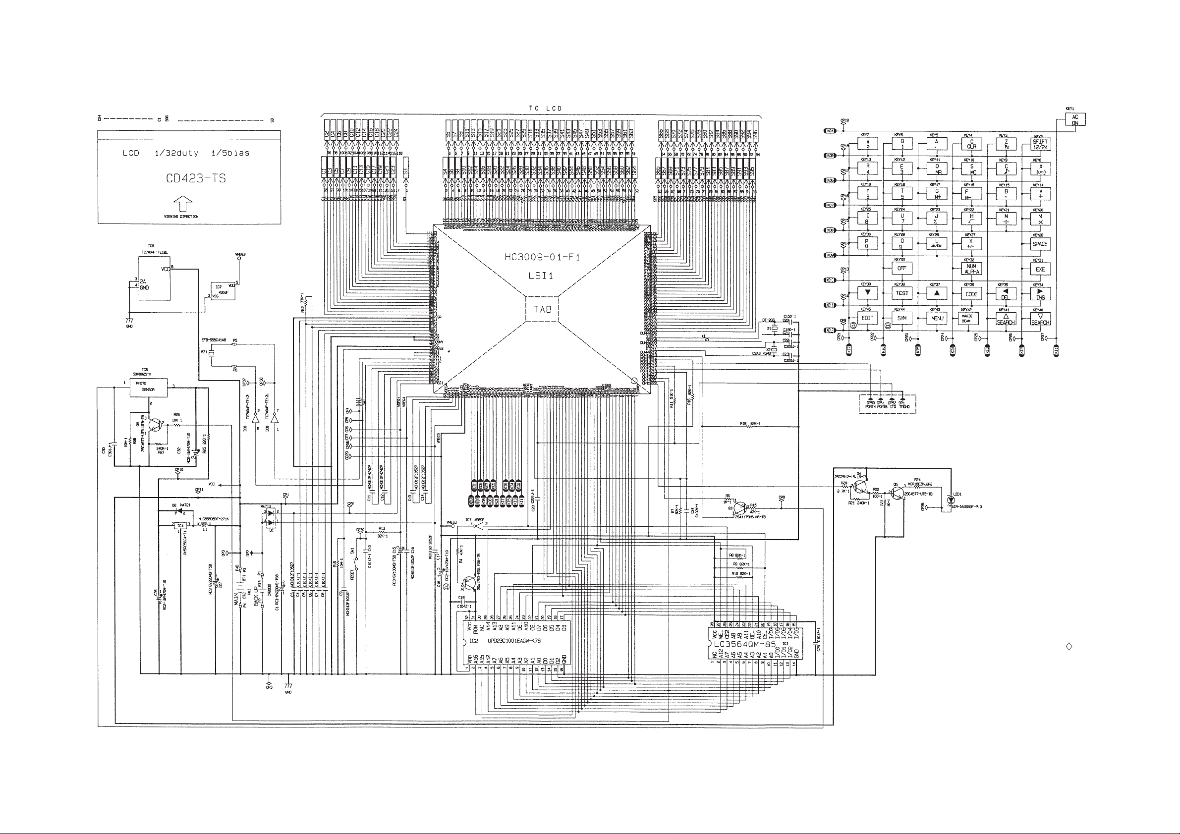
1. SCHEMATIC DIAGRAM
— 1 —
NOTES:
1. DP1, DP2, and DP3 are the checking
points for the power supply.
2. CP50, CP51, CP52, and DP1 are the
terminals for the data transfer.
3. The other terminals marked with
may be used to function checking.
Page 4

2. SPECIFICATIONS
Telephone Directory Mode
Storage and recall of telephone directory data (name, telephone number, portrait). Each item can contain
up to 380 characters with a Fun Face. Includes secret memory area and auto sort function.
Schedule Mode
Storage and recall of appointments (month/date/hour/minute, description). Includes secret memory area
and auto sort function.
Data Memo Mode
Storage and recall of memos (memo name, memo). Includes secret memory area and auto sort function.
Timekeeping Mode
Average of accuracy ±3 seconds per day under normal temperatures: year/month/date, hour/minute/
second, AM/PM, day of the week, full automatic calendar; 12/24 hour timekeeping format.
Alarm Mode
Daily Alarm (20-second electronic buzzer); Hourly Time Signal (beeps every hour on the hour).
Fortune Telling Mode
Fortune telling on any date from January 1, 1901 to December 31, 2099.
Match Maker Mode
Compatibility of any two people whose birthdays are from January 1, 1901 to December 31, 2099.
Triple Play Mode
1 Player and 2 Players (using Magic Beam).
Magic Beam Mode
Data communications using infra-red light (messages up to 28 characters long and Telephone Directory
data).
Calculator Mode
10-digit arithmetic calculations; constant calculations; memory calculations; 20-digit approximations;
percentage calculations; square roots; sign changes; function command signs
Other functions
Contrast adjustment
— 3 —
Page 5

General
Display: Liquid crystal display
Memory Capacity: 4,096 bytes
Power Supply: Main batteries – Two AAA-size batteries (LR03 (AM-4) or R03 (UM-4))
Back-up battery – One lithium battery (CR2032)
Power Consumption: 0.2 W
Battery Life: Main batteries –
LR03 (AM-4)
•approximately 250 hours continuous operation
•approximately 6 months (1 hour use per day)
R03 (UM-4)
•approximately 200 hours continuous operation
•approximately 5 months (1 hour use per day)
Back-up battery – approximately 1 year after the low main battery warning
appears on the display (approximately 5 years if main batteries are replaced immediately whenever battery warning
appears).
Auto Power Off: Approximately 6 minutes after last key operation
Ambient Temperature
Range: 0°C ~ 40°C (32°F ~ 104°F)
Dimensions: Open: 13.5 (H) × 145 (W) × 179.5 (D) mm
(1/2" (H) × 5 3/4" (W) × 7 1/8" (D))
Closed: 15.1 (H) × 145 (W) × 96.5 (D) mm
(5/8" (H) × 5 3/4 " (W) × 3 3/4" (D))
Weight: 138.2 g (4.9 oz) including batteries
* The batteries which have been installed in this unit when you purchase it are for the factory test, so it will not
Current consumption
Check point TYP [µA] Max [µA]
OFF CP1 - CP3 — 18
ON (Menu) CP1 - CP3 185 230
ON (Buzzer) CP1 - CP3 — 5000
ON (Infrared) CP1 - CP3 — 80000
How memory capacity is calculated
There is no limit on the amount of memory you can use in each mode, but the limit on the total amount of data
stored is 4,096 bytes. The following shows how many bytes the data in each mode takes up. One character
requires one byte of memory.
— 4 —
Page 6
Mode Bytes per Data Item
Telephone Directory (name) + (telephone number) + 15
Schedule (description) + 12
Data Memo (memo name) + (memo contents) + 3
Examples:
Telephone Directory data only
When all items use 10 characters for the name and 12 characters for the phone number, you can store
approximately 110 items.
Schedule data only
When all items use 20 characters, you can store approximately 120 items.
Data Memo data only
When all items use 10 characters for the memo name and 10 characters for the memo content, you can
store approximately 170 items.
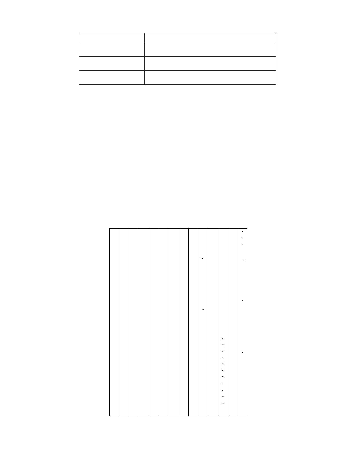
Sort Sequence
The following table shows the sequence used for sorting data in the Telephone Directory and the Data Memo
Modes.
1
2
3
4
5
6
7
8
9
10
11
12
13
14
15
16
17
18
19
20
21
22
23
24
25
26
27
28
29
§
→
←
÷
×
Space
!
”
#
$
%
&
’
(
)
∗
+
,
–
•
/
0
1
2
3
4
5
6
7
30
31
32
33
34
35
36
37
38
39
40
41
42
43
44
45
46
47
48
49
50
51
52
53
54
55
56
57
58
@
C
D
E
F
G
H
K
M
N
O
P
Q
R
S
T
U
"
o
146
Ì
117
t
88
V
59
8
Â
147
Ò
118
u
89
W
60
9
Ê
148
Ù
119
v
90
X
61
:
Î
149
Ç
120
w
91
Y
62
;
Ô
150
L
121
x
92
Z
63
<
y
93
„
64
>
z
94
¥
65
?
“
66
¡
67
A
¿
68
B
a
69
b
70
c
71
d
72
e
73
f
74
g
75
I
h
76
J
i
77
j
78
L
k
79
l
80
m
81
n
82
o
83
p
84
q
85
r
86
s
87
95
96
97
98
99
100
101
102
103
104
105
106
107
108
109
110
111
112
113
114
115
116
<
<
£
>
>
~
Á
É
Í
Ó
Ú
Ã
Õ
Ñ
á
é
í
ó
ú
ã
õ
ñ
À
È
122
123
124
125
126
127
128
129
130
131
132
133
134
135
136
137
138
139
140
141
142
143
144
145
Æ
Œ
æ
œ
.
Z
à
è
ì
ò
ù
ç
l
.
z
Ä
Ë
Ï
Ö
Ü
"
O
ä
ë
ï
ö
ü
151
152
153
154
155
156
157
158
159
160
161
162
163
164
165
166
167
168
169
170
171
172
173
174
Û
Å
.
U
"
U
â
ê
î
ô
û
å
.
u
"
u
A
E
C
D
N
R
S
T
a
e
c
d'
175
176
177
178
179
180
181
182
183
184
185
186
187
188
189
190
191
192
193
194
195
196
197
n
r
s
t'
A
E
`
´
C
´
N
´
S
´
Y
´
Z
Z
a
`
e
`
c
´
n
´
s
´
y
´
z
´
z
Ø
ø
ß
— 5 —
Page 7

3. GENERAL GUIDE
Very important stuff! Here's where we tell you how not to lose important data stored in memory. Also, be
sure to perform the all-reset operation before using the JD-5500/C-310 for the first time. The all-reset
operation is described in section 4.
Please be sure you understand the following before using the JD-5500/C-310.
Make back-up copies of important data!
The electronic memory in the JD-5500/C-310 store and recall information quickly and easily. But that
information is retained only as long as power is supplied by the batteries. Should the batteries go dead, or
should you remove both batteries at the same time, data stored in memory can be lost entirely. Data can
also be corrupted or lost due to a strong electrostatic charge, strong impact, or extremes in temperature
and humidity. All of this means that you should always keep written back-up copies of important data.
General Precautions
Warning!
• Never expose the unit or batteries to direct heat or flame.
• Avoid use or storage in very low temperatures. This may cause display response to slow down or fail
entirely. Very low temperatures can also shorten battery life.
• Avoid use or storage in very high temperatures. Even prolonged exposure to direct sunlight can damage
the unit. Leaving it on the dashboard of a closed car, or on a heater, is even worse.
• Avoid using or storing the unit where there is high humidity or a lot of dust. Never allow liquids to come
into contact with the unit.
• Avoid dropping the unit or otherwise subjecting it to strong impact.
• Never bend or twist the unit. Carrying it in your back pocket, for instance, can subject the JD-5500/C-310
to abnormal bending and twisting.
• Never try to take the unit apart.
• Do not press the unit's keys with a pen, pencil, or other sharp object.
• To clean the JD-5500/C-310, wipe it with a soft cloth. When necessary, you may wipe the exterior with
a soft cloth that has been dipped in a weak solution of a mild, neutral detergent and water.
• Never use strong liquid cleaners such as lacquer thinner or benzine to clean the unit.
• In no event will CASIO or its suppliers be liable to you or any other person for any damages, including
any incidental or consequential expenses, lost profits, lost savings, or any other damages arising out of
the use of this product.
MENU Key
Magic Beam Key
Symbol Key
Display
CODE Key
Clear Key
AC/ON Key
SHIFT Key
SERCH and CONTRAST Key
Edit Key
Cursor Keys
OFF Key
EXE Key
SPACE/Return Key
— 6 —
Page 8
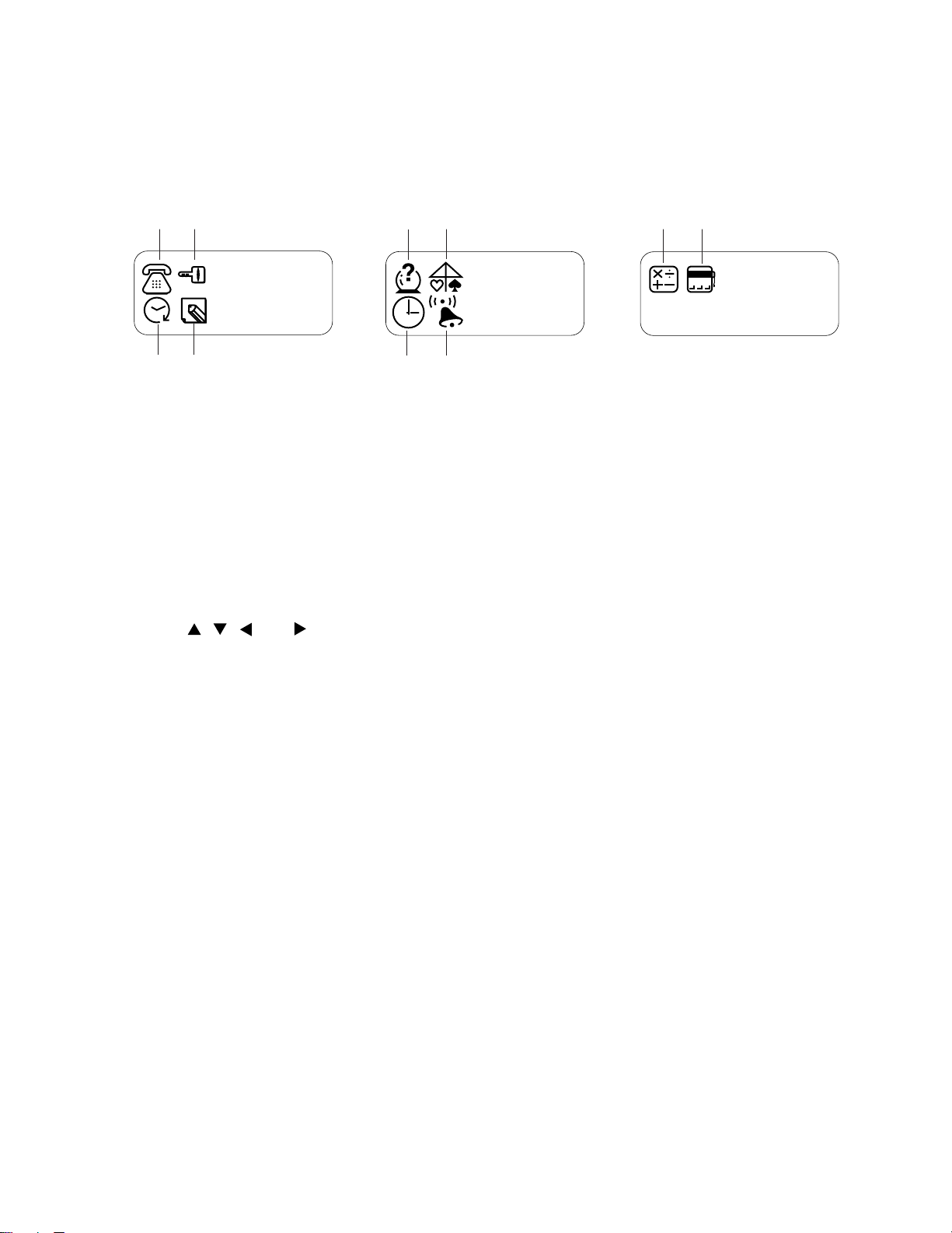
Displaying the Menues
There is a total of three icon menues which are named MENU 1, MENU 2, and MENU 3. An icon menu will
appear on the display once the switch is turnd on, and the other icon menues can be selected by using the
MENU key.
Icon menues
12
56
90
34
MENU 1
78
MENU 2
777
MENU 3
1Telephone Directory Mode 6 Match Maker Mode
2 Secret Memory Area 7 Timekeeping Mode
3 Schedule Mode 8 Alarm Mode
4 Data Memo Mode 9 Calculator Mode
5 Fortune Telling Mode 0 Triple Play Mode
To Change Modes
1. Press MENU to display the one of the menues, MENU 1, MENU 2, and MENU 3, that contains the mode
you want.
2. Use , , , and to move the hightlight to the icon of the mode you want.
3. While the icon you want is hightlighted, press EXE to enter its mode.
* Note that you have to press the MAGIC BEAM key if you hope to enter the Magic Beam Mode.
— 7 —
Page 9

Setting the System Language
The JD-5500/C-310 can display messages in any one of five languages: English, Spanish, Italian, German,
and French.
To set the system language
1. Press MENU to display any menu (MENU 1, MENU 2, or MENU 3).
2. Press EDIT and the " Language" appears on the screen.
3. Use or to select the language which you want to use.
* If you want to cancel this operation, press AC/ON.
4 Under the language you want being on the display, press EXE.
* After a few moments, the MENU from which you started out will reappear on the display.
To Adjust the Display Contrast
1. Press MENU to display a menu (MENU 1, MENU 2, or MENU 3).
2. Press to increase contrast (making the figures darker) or to decrease contrast (making the figures
lighter).
To Switch the Key Input Tone On or Off
1. Press MENU to display MENU 2.
2. Use , , , and to highlight , and then press EXE to enter the Alarm Mode.
3. While the current alarm time setting is shown, press e (C) to display the "Key Tone".
4. Use or to select the "ON" (key input tone on) or the "OFF" (key input tone off).
5. Press EXE to return to the current alarm time setting screen.
6. Press MENU to return to MENU 2.
Auto Power Off Function
This function automatically switches off the power if you do not touch any key of the unit for about six
minutes. Pressing AC/ON can restore the power.
— 8 —
Page 10

Features and Functions
Telephone Directory Mode
Store the names and phone numbers of your friends, along with their portraits.
Schedule Mode
Keep track of your promises and appointments.
Data Memo Mode
Store short memos and reminders.
Secret Memory Area
Keep your data private.
Timekeeping Mode
A built-in clock shows the current time.
Alarm Mode
An alarm sounds each day at the time you preset.
777
Fortune Telling Mode
Find out the fortunes of all your friends.
Match Maker Mode
Check how well two prople are matched.
Triple Play Mode
An exciting game you can play alone or with a friend.
Magic Beam Mode
Exchange data with your friends using infrared light.
Calculator Mode
A 10-digit calculator.
— 9 —
Page 11

Magic Beam Mode
It is possible for this unit to communicate with the following CASIO units: JD-5500, JD-6000, JD6000A, JD-7000, and JD-7000R using infrared light, without direct cable communication.
Effective range
Approximately 8 meters
(8.7 yards)
20°
Things to check for if you are having problems with Magic Beam
• If battery power is weak, you have to move the two units closer together.
• If the two units are at an angle of more than 20 degrees from each other, you have to move them closer
together.
• If an object is blocking the path between the two units, communication will be impossible.
• Outdoors, near a window, or in other brightly lit areas, you may have to move the two units closer together
or you may not be able to send data at all.
• If there is a third unit nearby, communication may be impossible.
— 10 —
Page 12

4. RESET OPERATIONS
Use the following operation to reset the unit and clear its memory.
Important!
• Be sure to reset the unit before using it for the first time.
• Do not use a very sharp pencil to press the RESET button. Doing so can damage the unit.
To reset the unit
1. Press AC/ON to switch power on.
2. Loosen the screw that holds the back-up battery compartment cover in place, and remove the cover.
RESET button
RESET
3. Use a thin, pointed object (like a paper clip) to press the RESET button inside the battery compartment
cover. When you do, the "Reset?" screen should appear.
4. Press to select "Yes" and then press EXE.
• MENU 1 appears on the display after all data is deleted.
5. Use the Timekeeping Mode to set the time after performing the RESET operation.
6. Replace the battery compartment cover.
• To abort the RESET operation, press to select "No" and then press EXE. This causes the "Check
time!" message to appear. Press EXE to display the time. If the time setting is wrong, use the
Timekeeping Mode to reset it.
• The following table shows what happens to all settings when you reset the unit.
Memory Data All Cleared
Data All cleared
Currrent Date January 1, 1990
Current Time Midnight (12:00 AM)
Time Format 12-hour
Alarms All off
Alarm Time Midnight (12:00 AM)
Password Cleared
Secret Memory Area Cleared
System Language English
— 11 —
Page 13

When the unit does not work properly ...
The unit may stop working properly after it is subjected to strong electrostatic charge or strong impact. If this
happens, first check to make sure that the main batteries and back-up battery are correctly installed, and then
perform the following operation.
1. Loosen the screw that holds the back-up battery compartment cover in place, and remove the cover.
2. Use a thin, pointed object (like a paper clip) to press the RESET button inside the battery compartment
cover. When you do, the "Reset?" screen should appear.
3. Make sure that the pointer is located at "No," and then press EXE. The "Check time!" message should
appear on the display.
4. Press EXE again, and then use the Timekeeping Mode to set the current time.
5. Replace the battery compartment cover.
— 12 —
Page 14

5. BATTERY REPLACEMENT
Low Battery Warning
The message, "Low Battery" appears whenever battery power drops below a certain level (about 2.70 V).
Replace the main battery immediately after this message appears.
Whenever the low battery warning message appears, the OFF key will be the only function that works. If you
don't turn the unit off yourself, power will switch off automatically about 30 seconds after the low battery warning
appears.
Replacing Batteries
• Main Batteries
Two AAA size batteries (LR03 (AM-4) or R03 (UM-4)) are used for the main power supply. The unit will not
operate at all if main batteries are not installed.
• Back-up Battery
One CR2032 lithium battery supplies power to the memory and protects its contents.
Memory contents are lost when both the main batteries and the back-up battery are removed. Be sure always
to leave one of the batteries or back-up battery in place to protect memory contents. If, however, you remove
the main battery for any time, memory retention will depend entirely on the condition of the back-up battery.
Over a long period of time with just the back-up battery in place, memory contents are likely to be damaged.
If memory seems corrupted, clear it using the RESET procedure described in section 4.
Important!
Incorrect use of batteries can cause them to burst or leak, possibly damaging the interior of the unit. Note the
following precautions:
• Be sure that the positive (+) and negative (-) poles of the batteries are facing in the proper direction.
• Never leave dead batteries in the battery compartment.
• Remove the batteries if you do not plan to use the unit for a long time.
• To avoid damage to the unit from leaky batteries, replace the main batteries at least once every two years,
and the back-up battery once every three years.
• Never mix batteries of different types.
Warning!
• Never try to recharge the batteries supplied with the unit.
• Do not expose batteries to direct heat, short-circuit them, or try to take them apart.
• Keep batteries out of the reach of small children. If swallowed, consult a physician immediately.
— 13 —
Page 15

To replace the main batteries
1. Switch power off.
2. Loosen the screw of the large battery compartment cover on the back of the unit, and slide the battery
compartment cover in the direction noted by the arrow. (Figure 1)
3. Remove the old batteries.
4. Making sure that the positive (+) and negative (-) ends of the batteries are facing correctly, load two new
batteries into the compartment. (Figure 2)
• Be sure to replace both old batteries with two new ones.
5. Insert the tabs on the bottom of the battery compartment cover into the slots of the battery compartment
and carefully close the cover. Secure the cover in place with the screw. (Figure 3)
Figure 1 Figure 2 Figure 3
To replace the back-up battery
1. Switch power off.
2. Loosen the screw of the small battery compartment cover on the back of the unit, and remove the back-
up battery compartment cover. (Figure 4)
3. Remove the old battery.
4. Wipe off a new battery with a soft cloth.Then, load it into the compartment making sure that positive (+)
side is facing up (so you can see it.) (Figure 5)
5. Insert the tabs on the bottom of the battery compartment cover into the slots of the battery compartment
and carefully close the cover. Secure the cover in place with the screw. (Figure 6)
Figure 4 Figure 5 Figure 6
— 14 —
Page 16

6. ERROR MESSAGE
Message
Error!
Check Time!
Memory Full!
No Record!
Not Found!
Mismatch!
Low Battery
Meaning
Magic Beam communication error.
Always appears when RESET
operation is aborted.
Memory is full.
No data stored in memory.
No data in memory matches data
specified for search.
Registered password does not
match input.
Battery power is low.
Action
Correct cause of problem and
try again.
Confirm that the current time
setting is correct.
Reduce number of characters
in data being stored, or delete
unneeded data from memory.
Store data before attempting
search operation.
Change specification.
Use correct password.
Replace main batteries.
— 15 —
Page 17

7. LSI PIN FUNCTION
1. CPU (HC3009-01-F1)
Pin No. Signal In/Out Function
1 DUMMY _ Not used
2 ~ 9 IO0 ~ 7 In/Out Data bus
10 CS6B0 Out Chip enable signal for ROM
11 CS7B0 Out Chip enable signal for RAM
12 DUMMY _ Not used
13 WEB0 Out Write enable signal for RAM
14 OEB0 Out Output enable signal for RAM and ROM
15 ~ 31 AO0 ~ 16 Out Address bus
32 AO17 Out Not used
33 IT0 In Reception data input
34 IT2 In Interrupt signal input
35, 37 DUMMY, TRANS _ Not used
36 BUFON Out Power supply control for ROM
38 ~ 44 KI1 ~ 7 In Key input signal
45 K18 In Not used
46 ~ 54 KO1, KO5 ~ 12 Out Key scan signal
55 DUMMY _ Not used
56 VREG3 Out Power supply for RAM/3(V)
57 VLCD Out 5.9[V]
58 ~ 61 VT1 ~ 4 _
62, 63 VREG1, 4 _ VREG1: 2.6[V]; VREG4: 5.0[V]
64 VDB In
65, 66 VD3, 4 _ VD3: 4.7[V]; VD4: 1.6[V]
67, 68 VD1, 2 _ VD1: 4.7[V]; VD2: 1.6[V]
69 SW1 In
70, 71 BZ1, 2 Out Buzzer terminal
72, 73 TS1, 2 _ Test for manufacturer
74 VREG2 Out 2[V]
75 VCC In Power supply /3[V]
76 DUMMY _ Not used
77, 78 VSS In GND/0[V]
79 ~ 83 V0 ~ 4 Out
VT1:
VT3:
Low battery detection
VDB < 4.4[V] -> Lower battery message
2.6[V]
While pushing the reset button:0[V]
The voltage for LCD drive
OFF:
ON
1.0[V]; VT2: 2.9[V]
2.0[V]; VT4: 3.9[V]
0[V]
V0: 3.6(Min) ~ 5.8(Max) [V]
V1: 2.9(Min) ~ 4.6(Max) [V]
V2: 2.1(Min) ~ 3.5(Max) [V]
V3: 1.4(Min) ~ 2.4(Max) [V]
V4: 0.7(Min) ~ 1.2(Max) [V]
— 16 —
Page 18

Pin No. Signal In/Out Function
84 VSSR In GND/0[V]
85 ~ 108 C1 ~ 24 Out Common signal display
109, 110 S1, S2 _ Not used
111 ~ 205 S3 ~ 96 Out Segment signal for display
206 DUMMY _ Not used
207, 208 XI, XO In/Out Clock terminal (DT-26S)
209 DUMMY _ Not used
210, 211 PO, PI In/Out Main clock terminal (3.45MG)
212 DUMMY _ Not used
213, 214 PORT2,3 _ Interrupt port
215 ~ 217 PORT4 ~ 6 In/Out For data communication
218 PORT7 _ Interrupt port
219 OPT2 _ Not used
220 OPT3 Out Turn on signal for Photo Sensor
221 OPT4 In Communication data through Photo Sensor
222 OPT5 Out Turn on signal for LED (Infrared)
2. RAM (LC3564QM-85)
Pin No. Signal In/Out Function
1 NC _ No connect
2 ~ 10 A0 ~ 7, A12 In Address bus
11 ~ 13 I/O 0 ~ 2 In/Out Data bus
14 GND In GND / 0[V]
15 ~ 19 I/O 3 ~ 7 In/Out Data bus
20 CE In Chip enable signal
21 A10 In Address bus
22 OE In Output enable signal
23 ~ 25 A8, 9, 11 In Address bus
26 CE2 In Chip enable signal
27 WE In Write enable signal
28 VCC In Power supply / 3[V]
— 17 —
Page 19

8. OPERATION CHECK
Note: (1) Please save all data stored in the unit to another unit by using the method described in
section 9 before starting this check program, because the data will be corrupted by this
operation.
(2)The TEST operation procedure shown below is defined as the short-circuit operation
metioned in section 9.
STEP
1
2
3
4
5
6
7
8
Reset
EXE
TEST
EXE
0
1
EXE
EXE
OPERATION
DISPLAY
Reset?
Y N
MENU 1
Cauti To Escape
on ! Press AC KEY
TEST
0.TES To Escape
1.SVC Press AC KEY
1.MEM 4.OPT(ZX806)
2.DSP 5.RESET
3.KEY
8K RAM OK!
ROM OK!
1.MEM 4.OPT(ZX806)
2.DSP 5.RESET
3.KEY
NOTE
Check buzzer
Check RAM
Check ROM
10
11
12
13
14
15
16
9
2
EXE
EXE
EXE
EXE
EXE
3
MENU MAGIC BEAM
EDIT ....... M
All dots are displayed
No display
Checkers are displayed
Reverse checkers are displayed
Frame is displayed
1.MEM 4.OPT(ZX806)
2.DSP 5.RESET
3.KEY
MENU
MAGIC BEAM, EDIT, ...
..., M, SPACE
Check display
Check display
Check display
Check display
Check display
Check key.
Push the key sequentially that appears on
the display.
Check key
— 18 —
Page 20

STEP
17
SPACE
OPERATION
DISPLAY
1.MEM 4.OPT(ZX806)
2.DSP 5.RESET
3.KEY
NOTE
18
19
20
21
22
4
The procedures mentioned
below are for the infra-red
transmission check. For this, it
is necessary that another unit,
as a receiver, takes part in the
check besides the present
unit. Here we call the present
unit unit1 and another unit2.
Both units have to be placed
facing each other and with the
space of about 30 cm between
them.
For UNIT2:
To take the procedures of the
steps 1 ~ 5.
For UNIT2: 4
For UNIT2: 2
1.TRAN
2.RCV/MASTER
1.MEM 4.OPT(ZX806)
2.DSP 5.RESET
3.KEY
1.TRAN
2.RCV/MASTER
OPT TEST
Receiving
Enter the infra-red
transmission mode
Enter the infra-red
transmission mode
Enter the receiving
mode
23
24
25
26
For UNIT1: 1
For UNIT1: EXE
For UNIT2: ON
For both units: 5
OPT OK
1.MEM 4.OPT(ZX806)
2.DSP 5.RESET
3.KEY
1.MEM 4.OPT(ZX806)
2.DSP 5.RESET
3.KEY
MENU 1
Normal
End
— 19 —
Page 21

9. TO SAVE THE DATA TO ANOTHER MACHINE
It is commonly necessary to save all data stored in the customer's unit before repairing it. For this
purpose, you can transfer the data of the JD-5500 or C-310 unit to another unit using the following
procedure.
(1)To reset the receiving unit
Please reset the unit used to receive the data from the customer's unit according to the method
mentioned in section 4.
(2)To connect transmission unit with receiving unit
Please remove the covers of button battery compartments from both the transmission unit and the
receiving unit, and connect one with another as shown in the figures below:
UNIT2
CP50
DP1
CP51
CP52
DTC114YK
GND
Tx
51K
MA704
1K
MA704
Rx
— 20 —
Page 22

(3)To do data transfer
Please switch both the units on, and make them enter the MENU1 mode. Thus you may start to transfer
all data of customer’s unit to the receiving unit following the procedure shown below.
AC
MENU 1
TEST Over 2 seconds TEST Over 2 seconds
Cauti To Escape
on! Press AC KEY
TEST
EXE
0.TES To Escape
1.SVC Press AC KEY
1
0.TRN
1.RCV
MENU 1
Cauti To Escape
on! Press AC KEY
TEST
EXE
0.TES To Escape
1.SVC Press AC KEY
1
0.TRN
1.RCV
AC
Receiving
failed
1
Receiving
Receiving succeeded
MENU 1
Rcv Error !
0
Sending succeeded
Sending
MENU 1
Send Error !
Sending
failed
Notes: The TEST means the short-circuit operation as shown in the figure on the next page.
— 21 —
Page 23

button battery
Shortcircuit the two shorting pads with a
shorting pin for over 2 seconds.
shorting pads
Shorting pin
— 22 —
Page 24

10. TROUBLESHOOTING
1. Intermittent display
START
Is the Heat seal defective ?
Is the battery contact weak ?
Are there short circuit around the pins
of the LSI (HC3009-01-F1) ?
Is the soldering weak ?
Replace the Z806-1 ass'y
2. Erratic display
Is the Heat seal defective ?
Is the LCD defective ?
Are the voltage V0 ~ V4 OK ?
Replace the Z806-1 ass'y
Y
N
N
N
N
START
N
N
Y
Are there short circuit around the pins of the
LSI (HC3009-01-F1) or between the 2 pins of
the crystal oscillator (·1) ?
N
Are there short circuit around
the pins of the RAM and ROM ?
N
Y
Y
Y
Y
Y
N
Y
Replace
Clean and adjust pressure of contact
Resolder
Resolder
Replace
Replace
Check or replace the chip
capacitors C4 ~ C8
Y
Resolder
Resolder
— 23 —
Page 25

3. No display
START
Is the battery contact weak?
Y
N
Is the battery switch contact weak?
N
Is the AC key contact weak?
Y
N
Are there short circuit around
Y
the pins of the LSI?
N
Is the voltage VCC 3[V] ?
N
Y
Does the ceramic oscillator oscillate ?
Y
Are the voltage V0 ~ V4 OK ?
Are the chip capacitors C22, C23 defective ?
Y
N
Is the heat seal defective ?
Is the LCD defective ?
Clean and adjust pressure of contact
Y
Clean and adjust pressure of contact
Clean or replace the rubber key
Resolder
Check or replace the electrolytic
capacitor C1
N
N
Replace the ceramic oscillator
Y
N
Y
N
Replace
Replace
Y
Replace
Are the voltage VD1 ~ VD4 OK ?
Y
Are the voltage VT1 ~ VT4 OK ?
Y
Are the voltage VREG 2 and
VREG 4 OK ?
Y
Is the voltage VREG 3 OK ?
N
Y
Is the voltage SW OK ?
N
Y
Replace the Z806-1 ass'y
N
Check or replace the chip
capacitor C11, C12
N
Check or replace the chip
capacitor C13, C14
N
Check or replace the chip
capacitor C9 or C16
Check or replace the chip
capacitor C18 or C25
Check or replace the chip
capacitor C10
— 24 —
Page 26

11. EXPLODED VIEW
44
18
11
22
14
9
2
13
— 25 —
1
4
5
DISASSEMBLY
1. Remove 2 screws
2. Remove 2 AAA-size batteries and 1 lithium battery.
12
3. Remove 3 screws
4. Remove 3 screws
P, then remove battery cover E and F.
\, then remove the Lower case 0.
S, then remove the Z806-1 ass'y 8.
6
3
LED1
8
43
IC6
LSI
10
30
33
34
35
32
29
21
19
29
23
6
7
29
31
28
27
24
37
17
20
25
21
40
39
36
38
41
Battery
26
15
16
26
42
Page 27

A : JD-5500 (Black case)
B : JD-5500 (Blue case)
C : JD-5500 (Green case)
12. PARTS LIST D : C-310
N Item Code No. Parts Name Specification M N.R.Yen R
Z806-1 ASS'Y
N C1,27 2803 7695 Electrolytic capacitor (v) RC3-6V220M-T58 222220 C
C11,12 2845 3486 Chip capacitor MCH312F474ZP 222210 C
N C15 2803 7611 Electrolytic capacitor (v) RC3-6V100M-T58 111120 C
N C16 2845 4942
N C18,26,32 2803 7597 Electrolytic capacitor (v) RC2-16V470M-T10 333320 C
C20 2845 1659
C21 2845 1652
C22,23 2845 2499
C24 2845 2030
C28 2845 1673
C3,9,13,14,17 2845 1925 Chip capacitor MCH312F105ZP 555510 C
C30 2845 3605
C4~8,10,19,25 2845 1540 Chip capacitor MCH212F104ZK
D1 2390 0364 Schottky diode MA713-TX 111110 C
D2 2390 0959 Chip diode MA721-TX 1111 5 C
IC1 2011 4088 LSI(RAM) LC3564QM-85 1111 1 B
N IC2 2011 9254 LSI(ROM) UPD23C1001EAGW-K78 11111 B
IC4 2105 2471 CMOS IC RH5RC502A-T1 11111 C
N IC6 3122 2576 Remote control receiver SBX8025-H 1111 1 C
IC7 2105 0686 L-MOS TC4S69F-TE85R 111110 C
IC8 2105 2898 L-MOS TC7W04F-TE12L 11115 C
L1 3841 0952 Coil NLC565050T-271K 1111 5 C
LED1 2370 0945 LED SIR-563SB3F-P,Q 111110 C
N LSI 6412 0440 COF3009-F1 sub ass'y A314072*1 11111 A
Q1 2250 0700 Chip transistor 2SA1753-ES5,ES6-TB 111120 C
Q3 2200 4417 Chip transistor 2SA1179M5,M6-TB 111120 C
Q4 2221 0378 Chip transistor 2SC2812-L5,L6-TB 111120 C
Q5,6 2252 0945 Transistor 2SC4577-UT5,UT6-TB 222220 C
R11 2796 1505
R12 2796 0315
R19,28 2795 2898
R20 2796 1239
R21,27 2796 1246
R22 2796 0266
R24 2795 4179
R25 2792 0807
R26 2796 0469
R4,15 2796 0476
R6,23 2792 0470
R7~10,13,16,18 2796 1519 Chip resistor RC210B82K-J-T
X1 7110 0642 Crystal oscillator DT-26S 111110 B
X2 2590 1498 Ceramic oscillator CSA3.45MG 11111 B
N 1 3335 5439 LCD CD423-TS 1111 1 A
N 2 5610 8200 Heat seal Z806 A314040-1 1111 5 A
3 6408 6940 Adhesive tape A-L172 A412891-4 222220 C
N 4 6412 0410 Tape A-Z806AH A415218-1 111120 B
N 5 6412 0360 Adhesive tape C-Z806AH A412891-8 111120 C
N 6 6412 0430 Blind tape B-Z806AH A415220-1 222220 C
Notes: N – New parts R – A : Essential
M – Minimum order/supply quantity B : Stock recommended
R – Rank C : Others
Chip capacitor MCH213F105ZP
Chip capacitor MCH215A150JK
Chip capacitor MCH215A180JK
Chip capacitor MCH215A300JK
Chip capacitor MCH215C102KK
Chip capacitor MCH215A221JK
Chip capacitor MCH215SL391JK
Chip resistor RC210B51K-J-T
Chip resistor RC210B33K-J-T
Chip resistor MCR10EZHJ106
Chip resistor RC210B2.7K-J-T
Chip resistor RC210B240K-J-T
Chip resistor RC210B100-J-T
Chip resistor MCR18EZHJ2R2
Chip resistor MCR10EZHJ470
Chip resistor RC210B10K-J-T
Chip resistor RC210B47K-J-T
Chip resistor MCR10EZHJ102
— 27 —
Quantity
ABCD Unit Price
111120 C
111120 C
111120 C
222220 C
111120 C
111120 C
111120 C
88820 C
8
111120 C
111120 C
222220 C
111120 C
222220 C
111120 C
111120 C
111120 C
111120 C
222220 C
222220 C
77720 C
7
X : No stock recommended
FOB Japan
Page 28

N Item Code No. Parts Name Specification M N.R.Yen R
Quantity
FOB Japan
ABCD Unit Price
7 6408 6960 Tape D-L172 A414156-1 111120 X
N 43 6409 8360 Tape F-L173AH A414728-2 222220 C
N 8 6413 2880 Z806-1 ASS'Y A111142C*1 1
1111
B
COMPONENTS
N 9 6412 0240 Upper case Z806AH A110917-15 10005 C
N 9 6412 0470 Upper case Z806BH A110917-16 01005 C
N 9 6412 0790 Upper case Z806DH A110917-18 0010 5 C
N 9 6412 0630 Upper case Z806CH A110917-17 0001 5 C
10 6408 7500 Lower case L172 A110924-1 1000 5 C
N 10 6412 0480 Lower case Z806BH A110924-18 0100 5 C
10 6409 4850 Lower case L172AHA A110924-8 0010 5 C
10 6409 3760 Lower case L173BH A110924-6 0001 5 C
N 11 6412 0260 Hard case Z806AH A111133-1 1000 5 X
N 11 6412 0490 Hard case Z806BH A111133-2 0100 5 X
N 11 6412 0810 Hard case Z806DH A111133-4 0010 5 X
N 11 6412 0650 Hard case Z806CH A111133-3 0001 5 X
N 12 6412 0270 Rubber key A-Z806AH A211215-12 10005 C
N 12 6412 0500 Rubber key A-Z806BH A211215-13 01005 C
N 12 6412 0820 Rubber key A-Z806DH A211215-15 00105 C
N 12 6412 0660 Rubber key A-Z806CH A211215-14 00015 C
N 13 6412 0290 Rubber key B-Z806AH A211381-7 10005 C
N 13 6412 0520 Rubber key B-Z806BH A211381-8 01005 C
N 13 6412 0840 Rubber key B-Z806DH A211381-10 00105 C
13 6409 3800 Rubber key B-L173B A211381-3 0001 5 C
14 6408 6290 Knob L172AA A211375-2 100020 C
N 14 6412 0510 Knob Z806B A211375-12 010020 C
14 6409 4900 Knob L172AAA A211375-7 001020 C
14 6409 3810 Knob L173BA A211375-5 000120 C
15 6408 7540 Battery cover A-L172 A313335-1 100020 C
N 15 6412 0530 Battery cover A-Z806BH A313335-13 010020 C
15 6409 4870 Battery cover A-L172AHA A313335-8 001020 C
15 6409 3850 Battery cover A-L173BH A313335-6 000120 C
16 6408 7550 Battery cover B-L172 A313344-1 100020 C
N 16 6412 0560 Battery cover B-Z806BH A313344-13 010020 C
16 6409 4880 Battery cover B-L172AHA A313344-8 001020 C
16 6409 3860 Battery cover B-L173BH A313344-6 000120 C
17 6408 6320 Filter L172AA A313338-2 111120 X
N 18 6412 0350 Display window Z806AH A314071-1 1000 5 B
N 18 6412 0580 Display window Z806BH A314071-2 0100 5 B
N 18 6412 0900 Display window Z806DH A314071-4 0010 5 B
N 18 6412 0740 Display window Z806CH A314071-3 0001 5 B
19 6408 7560 Hinge R-L172 A313339-1 101120 C
19 6410 8160 Hinge R-L172RHU A313339-8 010020 C
N 19 6412 0700 Hinge R-Z806CH A313339-13 000120 C
20 6408 7570 Hinge L-L172 A313340-1 101120 C
20 6410 8170 Hinge L-L172RHU A313340-8 010020 C
N 20 6412 0710 Hinge L-Z806CH A313340-13 000120 C
21 6408 6240 Hinge blind L172 A414167-1 202220 X
N 21 6410 8180 Hinge blind L172RHU A414167-5 020020 X
N 21 6412 0760 Hinge blind Z806CH A414167-10 000220 X
N 22 6412 0380 Label A-Z806AH A414151-11 1000 5 X
N 22 6412 0590 Label A-Z806BH A414151-12 0100 5 X
Notes: N – New parts R – A : Essential
M – Minimum order/supply quantity B : Stock recommended
R – Rank C : Others
— 28 —
X : No stock recommended
Page 29

N Item Code No. Parts Name Specification M N.R.Yen R
N 22 6412 0910 Label A-Z806DH A414151-14 00105 X
N 22 6412 0750 Label A-Z806CH A414151-13 00015 X
23 6408 0100 Battery spring A-L370 A410112-3 111120 X
24 6408 6710 Battery spring B-L172 A412984-2 111120 X
25 6408 6720 Battery spring C-L172 A412985-2 111120 X
26 6408 6730 Decoration screw L172 A412299-7 202020 B
N 26 6409 5790 Decoration screw L173B A412299-8 000220 B
27 6408 6740 Nut L172 A411563-4 111120 X
28 6408 0230 Insulation seal L375 A43065-2 222220 X
29 6327 1850 Screw A-G198 A44508-1 333320 X
30 6408 0091 Battery spring A-L375 A33938-3 111120 X
31 6408 0010 Battery spring A-L375 A311808-3 111120 X
N 32 3122 2380 Buzzer EFB-S55C41A8 111110 C
33 6408 0240 Battery insulation seal L375 A45154-6 111110 X
34 6408 6780 Buzzer adhesive tape L172 A45381-3 111120 C
35 6408 6790 Tape B-L172 A411609-4 111120 C
36 6408 6820 Blind L172 A413625-3 111120 C
37 6408 6830 Nut L172 A413891-2 111120 X
38 6407 9930 Flat screw A-L370 A310044-41 333350 X
39 6391 8831 Rubber key V160 A311024-1 111120 C
N 40 6412 0340 Jack cover Z806AH A314069-1 100020 X
N 40 6412 0570 Jack cover Z806BH A314069-2 010020 X
N 40 6412 0890 Jack cover Z806DH A314069-4 001020 X
N 40 6412 0730 Jack cover Z806CH A314069-3 000120 X
41 6403 0340 FCC Label L387H A412826-2 001020 X
42 6408 6251 Label B-L172 A414172A-1 100020 X
N 42 6412 0611 Label B-Z806BH A414172A-9 010020 X
42 6409 4841 Label B-L172A A414172-4 001020 X
42 6409 3951 Label B-L173B A414172-3 000120 X
N 44 6413 1353
Seal Z806DH A413061-C17
Quantity
ABCD Unit Price
111120 X
FOB Japan
Notes: N – New parts R – A : Essential
M – Minimum order/supply quantity B : Stock recommended
R – Rank C : Others
— 29 —
X : No stock recommended
Page 30

8-11-10, Nishi-Shinjuku
Shinjuku-ku, Tokyo 160, Japan
Telephone: 03-3347-4926
 Loading...